

Page 1
Page 2

TABLE OF CONTENTS
1.0 IMPORTANT INFORMATION 05
1.1 Information about this manual 05
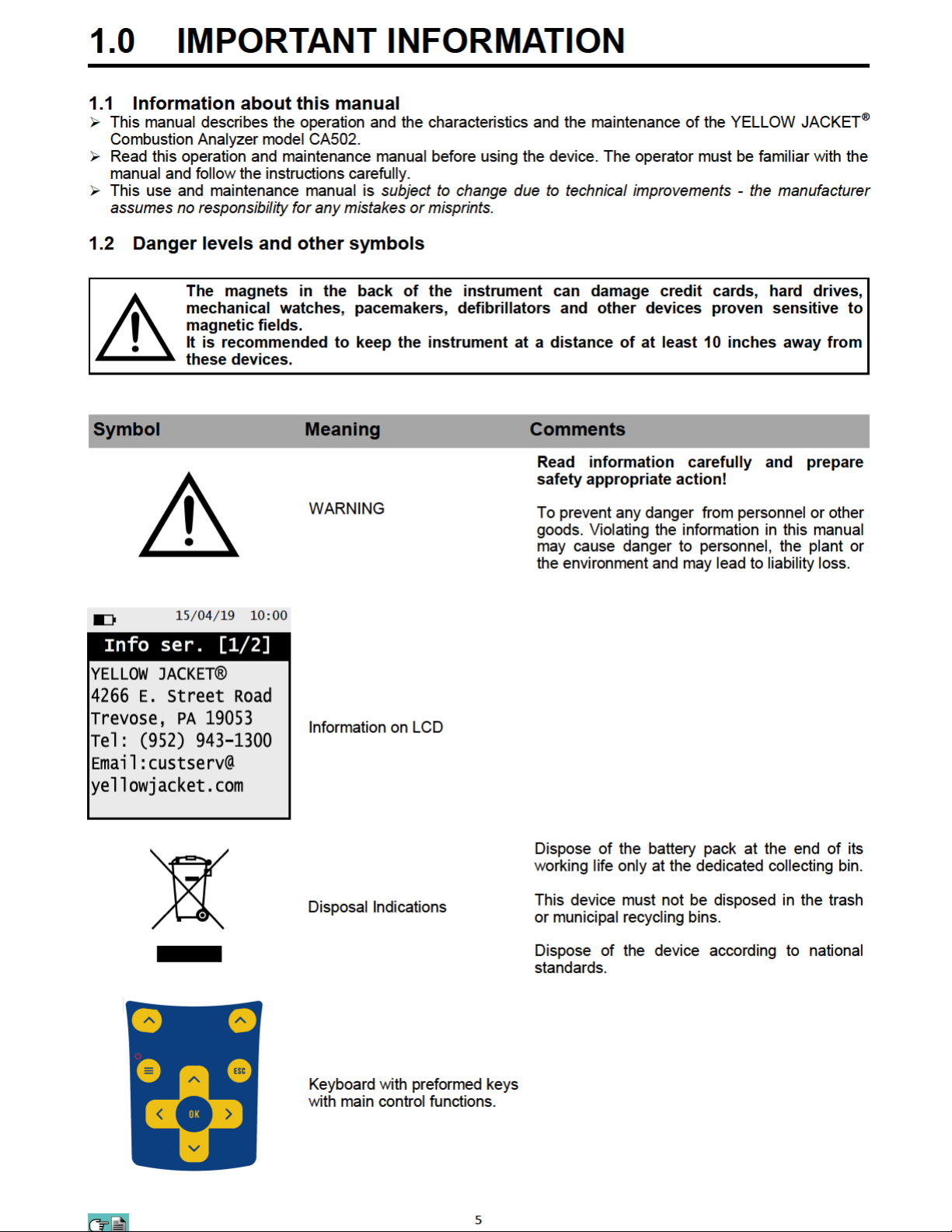
1.2 Danger levels and other symbols 05
2.0 SAFETY 06
2.2 Safety check 06
2.2 Intended purpose 06
2.3 Improper use of the product 06
2.4 Precautions for the usage of the Li-Ion battery package 06
3.0 WORKING PRINCIPLE 07
3.1 General overview of the analyzer 07
4.0 DESCRIPTION OF THE PRODUCT 08
4.1 Working principle 08
4.2 Measurement cells 08
4.3 Fuel types 08
4.4 Sample treatment 08
4.5 Pressure sensor, piezoelectric, temperature compensated 08
4.6 Suction pump 08
4.7 Draft measurement with sensor automatic autozero 08
4.8 Bluetooth® connection 09
4.9 IR connection 09
4.10 Available software and applications 09
5.0 COMPONENTS DESCRIPTION 10
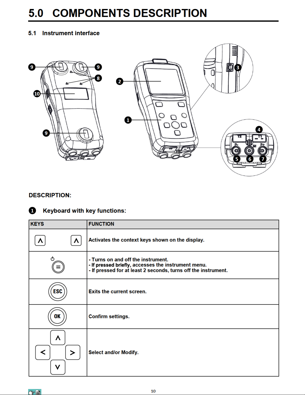
5.1 Instrument interface 10
6.0 TECHNICAL SPECIFICATIONS 12
6.1 Technical specifications 12
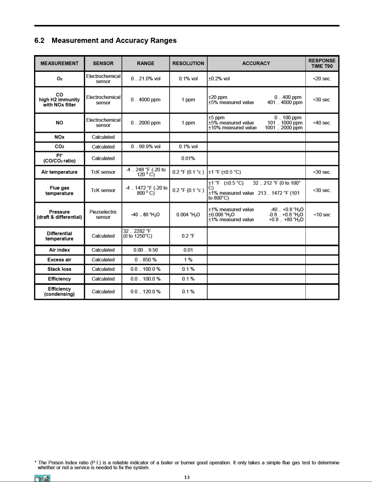
6.2 Measurement and Accuracy Ranges 13
7.0 USING THE FLUE GAS ANALYZER 14
7.1 Preliminary operations 14
7.2 Warning 14
7.3 Analyzer power supply 14
7.3.1 Internal battery charge level 14
7.3.2 Use with external power pack 15
7.4 QR code generation 15
7.5 Connection diagram 16
8.0 FLUE GAS ANALYSIS 17
8.1 Flue gas analysis 17
8.1.1 Switching on the instrument and out-calibration 17
8.1.2 Preliminary operations 18
8.1.3 Inserting the probe inside the stack 18
8.1.4 Performing the combustion analysis - manual mode 19
8.1.5 Performing the combustion analysis - auto mode 20
8.1.6 End of the analysis 22
2
Page 3

TABLE OF CONTENTS
9.0 INSTRUMENT PARAMETER 24
9.1 Setting Menu 24
10.0 MEASUREMENTS 25
10.1 Menu→Measurements 25
10.2 Menu→Measurements→Comb. analysis 26
10.3 Menu→Measurements→Draft 27
10.4 Menu→Measurements→CO air 28
10.5 Menu→Measurements→Pressure 29
11.0 MEMORY 30
11.1 Menu→Memory 30
12.0 CONFIGURATION 33
12.1 Menu→Configuration 33
12.2 Menu→Configurationan→Analysis 34
12.2.1 Menu→Configuration→Analysis→Fuel 35
12.2.2 Menu→Configuration→Analysis→Condensation 36
12.2.3 Menu→Configuration→Analysis→O2 Reference 37
12.2.4 Menu→Configuration→Analysis→Measure units 38
12.2.5 Menu→Configuration→Analysis→Autozero 39
12.2.6 Menu→Configuration→Analysis→Air temp 40
12.3 Menu→Configurationan→Instrument 41
12.3.1 Menu→Configuration→Instrument→Display 42
12.3.2 Menu→Configuration→Instrument→Clock 43
12.3.3 Menu→Configuration→Instrument→Bluetooth® 44
12.4 Menu→Configuration→Alarm 45
12.5 Menu→Configuration→Print 46
12.5.1 Menu→Configuration→Print→Pairing 47
12.6 Menu→Configuration→Language 48
12.7 Menu→Configuration→Reset 49
13.0 DIAGNOSTIC 50
13.1 Menu→Diagnostic 50
13.1.1 Menu→Diagnostic→Sensors 51
13.1.2 Menu→Diagnostic→Gas probe 52
13.1.3 Menu→Diagnostic→Hardware 53
14.0 INFO SERVICE 54
15.0 SENSORS 55
15.1 Sensors→Sensors arrangement 55
15.2 Sensors→ Sensor types and relevant positioning 55
15.3 Sensors→ Gas sensors life 55
15.4 Sensors→ Gas sensors life table 55
16.0 MAINTENANCE 56
3
Page 4

TABLE OF CONTENTS
16.1 Maintenance→Routine maintenance 56
16.2 Maintenance→Preventive maintenance 56
16.3 Maintenance→Gas sensors replacing 57
16.4 Maintenance→Replacing the battery pack 59
17.0 FIRMWARE UPDATE 60
18.0 TROUBLESHOOTING 61
18.1 Troubleshooting→Troubleshooting guide 61
19.0 SPARE PARTS AND SERVICING 63
19.1 Spare parts and servicing→Spare parts 63
19.2 Spare parts and servicing→Accessories 63
19.3 Spare parts and servicing→Service Centers 63
ANNEX A - Analysis report examples 64
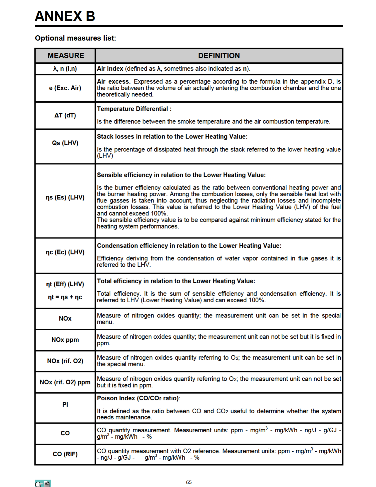
ANNEX B - Optional measurements list 65
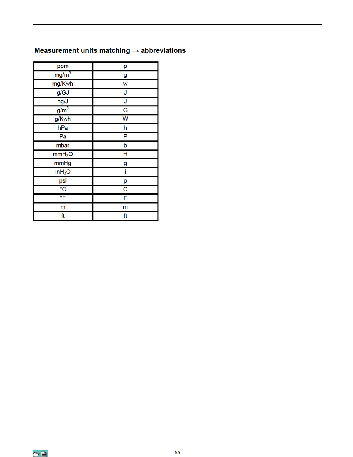
Measurement units matching → abbreviations 66
ANNEX C - Coefficients of the fuels and Formulas 67
WARRANTY CERTIFICATE 68
YELLOW JACKET® - ALL RIGHTS RESERVED -
Total or partial reproduction of this document by any means (including photocopying
or storage on any electronic medium) and transmittal of same to third parties in any
manner, even electronically, is strictly prohibited unless explicitly authorized in writing
by YELLOW JACKET®.
4
Page 5
Page 6

2.0 SAFETY
2.1 Safety check
• Use the product according to what is described in the section “Intended purpose”.
• During the instrument operation, comply with the current standards.
• Do not use the instrument if damaged on the outer cover, on the power supply plug or on the cables.
• Do not take measures on non-isolated components / voltage conductors.
• Keep the instrument away from solvents.
• For the maintenance of the instrument, strictly comply with what’s described in this manual at the
“Maintenance” chapter.
• All the updates or changes not specified in this manual, may be performed exclusively by YELLOW JACKET
service centers. YELLOW JACKET® is not responsible for changes performed by noncertified service centers
or for the operation of the instrument and on the validity of the certification.
2.2 Intended purpose
This chapter describes the areas of application for which the CA502 is intended.
Using the CA502 in other application areas transfers the risk to the operator and the manufacturer assumes no
responsibility and liability for loss, damage or costs which could be a result. It is mandatory to read and pay
attention to the Use And Maintenance manual.
All products of the series CA502 are handheld measuring devices in professional flue gas analysis for:
• Small furnaces (burning oil, gas, wood, coal)
• Low-temperature and condensing boilers
• Gas heaters
®
2.3 Improper use of the product
The CA502 should not be used:
• As safety alarm instrument
• In classified zones with explosion risk (ATEX or equivalent)
2.4 Precautions for the usage of the Li-Ion battery package
Pay attention while handling the battery package inside the instrument; a wrong or improper usage may lead to
heavy physical injuries and/or damages:
• Do not create a short circuit: make sure that the terminals are not in contact with metal or other conductive
materials during transportation or storage.
• Do not apply with inverted polarities.
• Do not make the batteries come in contact with liquid substances.
• Do not burn the batteries nor expose to temperature higher than 140 °F (60°C).
• Do not try to disassemble the battery.
• Do not provoke collisions or pierce the batteries. Improper use can cause damages and internal short circuits
not always externally visible. If the battery package has fallen or has been hit with an hard surface, regardless
the external shell condition:
• Stop operation
• Dispose of the battery in compliance with the disposal instructions
• Do not use batteries with leaks or damages.
• Charge the batteries only inside the instrument.
• If a malfunction occurs or if over heating signs occur, immediately remove the battery package from the
instrument. Warning: the battery may be hot.
6
Page 7

3.0 WORKING PRINCIPLE
3.1 General overview of the Analyzer
CA502 is a portable industrial analyzer for flue gas and emissions monitoring.
The instrument is equipped with:
− Pneumatic line able to manage up to 2 sensors.
− Easy and immediate user interface so it could be used without the manual support.
− Wide and bright graphic display, White / Black 2” x 2” (50x55 mm).
− Rechargeable 'Li-Ion' battery.
− Supplied with the device is a charging cord with output 5V , 2A to charge the internal batteries. When
needed, it is possible to recharge the instrument battery using a power bank, as long as it is equipped with 5
volts output and 1A minimum current.
Main functions:
- Combustion analysis in manual.
- Comes with the 15 most used fuels (such as natural gas, LPG, gas oil and fuel oil).
- Generation and visualization of a QR code with the purpose of downloading the data of the acquired
measures, having installed the YJ Combustion App which can be downloaded from the AppStore and
PlayStore
Measured values:
- O
2
- CO
- Combustion air temperature
Gas pressure in the piping, pressure in the burning chamber and check of the pressure switches, using the
measurement range up to 5.9 in hg (200hPa).
- Pressure measurement
- Pressure measurement of the gas inlet line
- CO environment measurement (via the internal sensor)
- Draft measurement
Calculated values:
- Stack leaks
- Combustion efficiency
- CO
2
- NO
X
- Air excess
- Poison index (CO/CO2 ratio)
Maintenance:
- O2 Sensors can be replaced by the user without having to ship the instrument to the service center, because
the spare sensors delivered are pre-calibrated.
- The instrument requires annual calibration.
Certificate of calibration
The instrument is accompanied with a calibration certificate, according to the ISO/EN 17025 standard.
7
Page 8

4.0 DESCRIPTION OF THE PRODUCT
4.1 Working principle
− The gas sample is taken in through the gas probe, by a diaphragm suction pump inside the CA502.
− The measuring probe has a sliding cone that allows the probe to be inserted in holes with a diameter of 11 mm
to 16 mm and to adjust the immersion depth: it is recommended to have a gas sampling point roughly in
the center of the flue/stack.
− The gas sample is cleaned of moisture and impurities by a condensate trap and filter located in-line in the tubing
for the CA502.
− The gas is then analyzed in its components by an on-board electrochemical cell.
− The electrochemical cell guarantees high precision results in a time interval of up to about 60 minutes during
which the CA502 can be considered very stable.
− When measurements are going to take a long time, we suggest auto-zeroing the CA502 again and flushing the
inside of the pneumatic circuit with clean air.
− During the zero calibrating phase, the instrument aspirates clean air from the environment and detects the cells’
drifts from zero (20.95% for the O2 cell), then compares them with the programmed values and compensates
them.
4.2 Measurement cells
− The instrument takes advantage of pre-calibrated gas sensors for the measurement of Oxygen (O2), Carbon
Monoxide (CO) and optional Nitric Oxide (NO/NOx).
− The sensors do not need particular maintenance, however, they have to be replaced periodically when they
reach their end of life.
− If sensors of toxic gases are used with concentrations higher than 50% of their measurement range for more
than 10 minutes continuously, they can show up to a ±2% drift as well as a longer time to return to zero.
− In this case, before turning off the analyzer, it is advisable to wait for the measured value to be lower than
20ppm by intaking clean air.
− The CA502 is intended to have a cleaning cycle of the pneumatic circuit. The duration of the cycle depends on
what has been set in the menu Configuration→Analysis→Autozero.
− Used O2 sensors can be easily replaced by the user without a complicated calibration procedure with certified
mixtures as they are pre-calibrated before being shipped.
− YELLOW JACKET
laboratory or other approved laboratory.
®
certifies the accuracy of the measurements only with a calibration certificate issued by its
4.3 Fuel types
The CA502 device is provided with the technical data of the most common types of fuels stored in its memory.
For more details see Appendix C.Coefficients of the Fuels and Formulas
4.4 Sample treatment
The flue gas suction line has an inline anti-condensation trap with dust filter. The trap and filter condition the gas
sample to be analyzed to be properly dried and cleaned of solid residues of combustion.
4.5 Pressure sensor, piezoelectric, temperature compensated
− The CA502 has a piezoresistive differential pressure sensor which can be used for measuring the draft
(vacuum) in the stack for differential pressure measurement and possibly for other measurements (pressure of
gas in the piping, pressure loss across a filter, etc.).
− The measurement range is –2.95 in hg to 5.9 in hg (-10,000 Pa .. +20,000 Pa.)
− Drift of the sensor is minimized with the autozeroing built into the system.
WARNING
ANY PRESSURE APPLIED TO THE SENSOR GREATER THAN ±8.89inHg (±300 hPa) MAY
CAUSE A PERMANENT DEFORMATION OF THE MEMBRANE, THUS DAMAGING
IRREVERSIBLY THE SENSOR ITSELF.
4.6 Suction pump
The diaphragm pump located inside the instrument, is operated with a DC motor. It is used to obtain the optimal
suction flow rate of the flue gas for the ongoing analysis.
4.7 Draft measurement with sensor automatic autozero
− CA502 performs the draft measurement.
− The sensor autozero allows for zeroing of the sensor and must be done with the gas probe NOT inserted in
the stack.
8
Page 9

4.8 Bluetooth® connection
− The CA502 analyzer is equipped with a Bluetooth
Bluetooth® printer
− The maximum transmission range in open field is 100 meters (Class 1 Bluetooth
− communication companion is also equipped with a Class1 Bluetooth
− This option allows freedom of movement for the operator who is no longer tied directly to the instrument for
®
module, which allows the communication with a remote
®
®
interface.
module), provided that the
acquisition and analysis.
4.9 IR connection
The CA502 analyzer is equipped with an infrared light interface which uses the HP-IR protocol, which allows the
communication with a remote IR printer.
4.10 Software and available applications
YJ Combustion App
This APP, allows the user the ability to scan the QR code generated by the CA502 to download the data of the
performed analyses and/or measures and store, email, or print the report.
9
Page 10
Page 11

Page 12

6.0 TECHNICAL SPECIFICATIONS
6.1 Technical specifications
Power: Li-Ion battery pack with internal protection circuit.
Average life of the battery package: 500 empty / full charge cycles.
Battery charger: External 5Vdc 2A battery charger with female A-type USB connector +
connection to the device with the serial communication cable supplied.
Charging time: 5 hours to charge from 0% to 90% (6 hours for 100%). The device can also
be charged by connecting it to the PC, the device must be turned off, the
charging time depends on the output current from the PC and may be more
than 12 hours.
Instrument working time: 8 hours of non-stop operation with display brightness at 50%.
——————————————————————————————————————————————————
Display: Graphic white LED backlit White / Black, 128 x 128 pixel
——————————————————————————————————————————————————
Connectivity:
Communication port: USB connector type B.
Bluetooth® Class 1. Communication distance <328’ (100 meters) (in open field)
Infrared interface: For external printer (optional) using protocol HP-IR.
——————————————————————————————————————————————————
Autozero: Settable (30 .. 600 seconds)
——————————————————————————————————————————————————
Gas measurement sensors: Up to 3 electrochemical sensors
Type of combustible: 12 predefined by the factory.
————————————————————————————————————————–——————--——--
Self-diagnosis: Checks all functions and internal sensors and reports any abnormal
operation.
Temperature measurement: Input for thermocouple type K with mignon connector (ASTM E 1684-96) for the
temperature measurement.
Room temperature measurement: Through the internal sensor and/or acquisition through the gas probe
positioned in air.
——————————————————————————————————————————————————
Internal data memory: 5 complete analyses.
——————————————————————————————————————————————————
Suction pump: 0.26 gal. per minute (1.0 l/min) of flue gas at 32.15 inH2O (80hPa).
——————————————————————————————————————————————————
Condensate trap:
Type: Outside the instrument.
Line filter: With replaceable filter (68612), 99% efficient with 20um particles.
——————————————————————————————————————————————————
Condensing boiler efficiency: Automatic recognition of the condensing boiler, with calculation and printout
of efficiency (>100%) on the LHV (Lower Heating Value).
Environmental gases: Measurement and separate printout of the ambient CO values.
Draft test: By using the internal sensor connected to the port P+.
——————————————————————————————————————————————————
Operating temperature range: 23°F .. 113°F (-5°C .. +45°C)
Storage temperature range: -4°F .. 122°F (-20°C .. +50°C)
Humidity limit: 20% .. 80% RH
Protection grade: IP42
Air pressure: Atmospheric
Outer dimensions: Analyzer: 2.8 x 2.4 x 6.7 inches (Width x Depth x Height)
Case: 15.7 x 11.4 x 4.7 inches (Width x Depth x Height)
Weight: Analyzer: ~ 0.77lbs (12.3 Oz)
——————————————————————————————————————————————————
12
Page 13
Page 14
Page 15
Page 16
Page 17
Page 18
Page 19
Page 20
Page 21
Additional Information
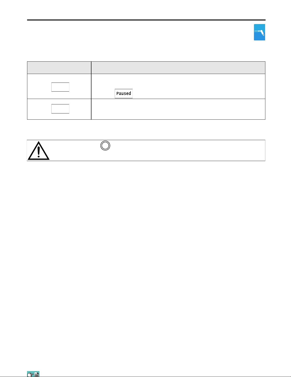
INTERACTIVE OPERATION DESCRIPTION
Pause
analysis when the set time interval is over. This condition is shown with the
symbol “ “.
By pushing the button related to this function, the CA502 stops the current
Keep
When the “Paused” phase is over, the interactive function “Keep” is shown. By
activating this function the recorded sample is stored to memory and the CA502
continues with the collection of the next sample.
BY PRESSING THE BUTTON AT ANY MOMENT, IT INTERRUPTS THE COMBUSTION
ESC
ANALYSIS AND GOES BACK TO THE MAIN SCREEN.
21
Page 22
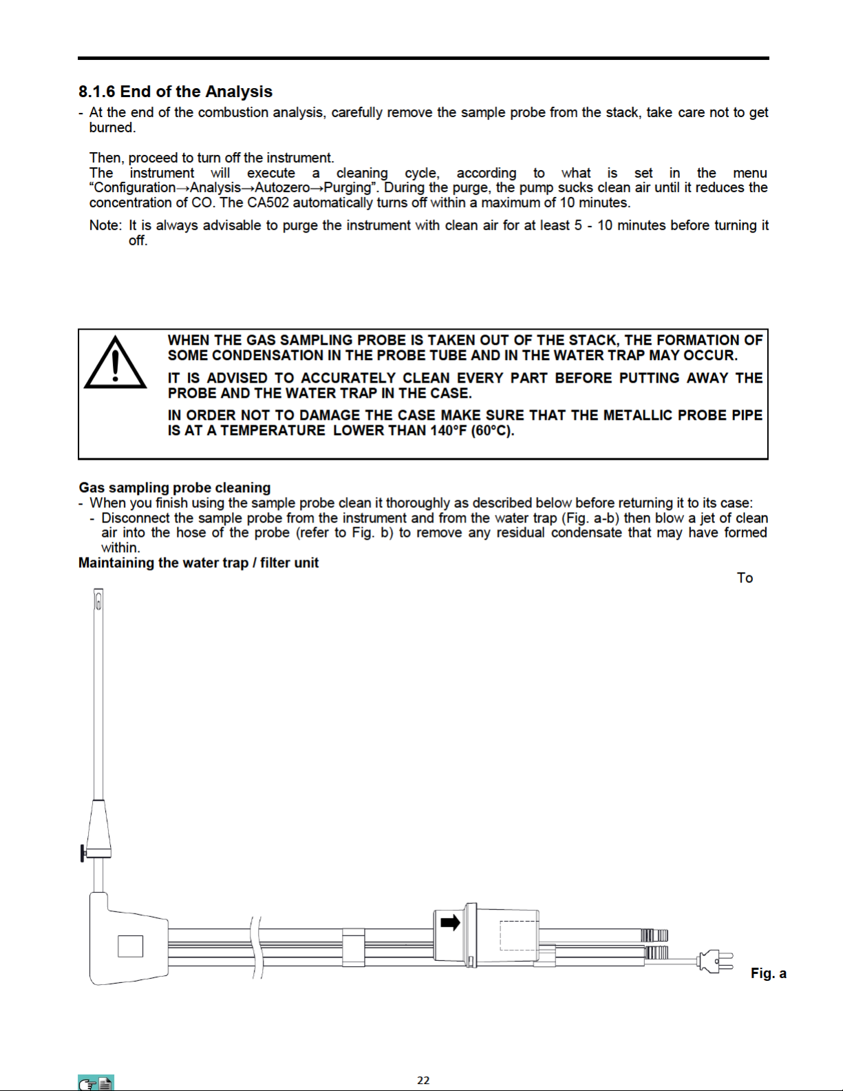
Page 23
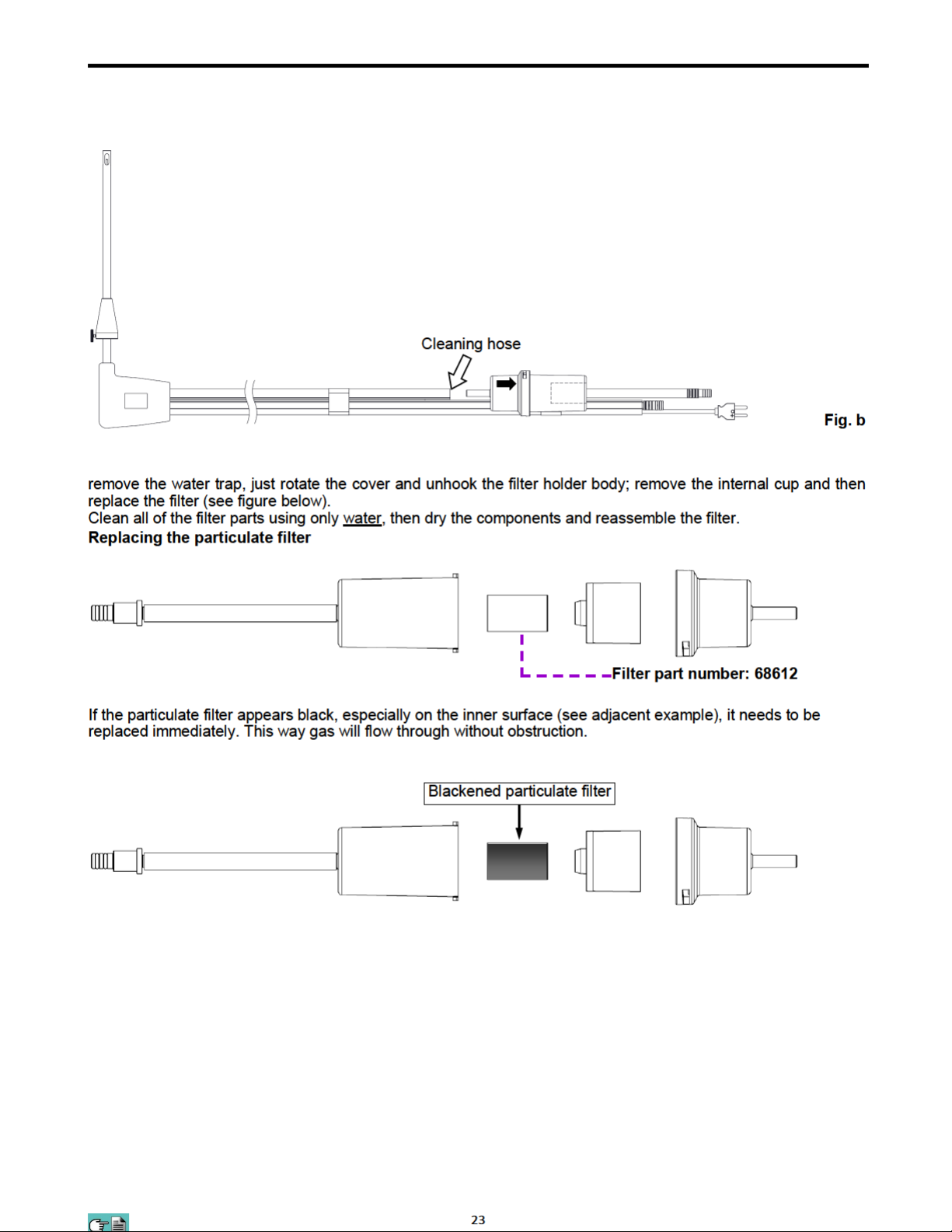
Page 24
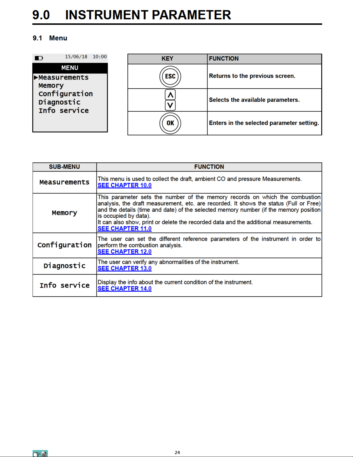
Page 25
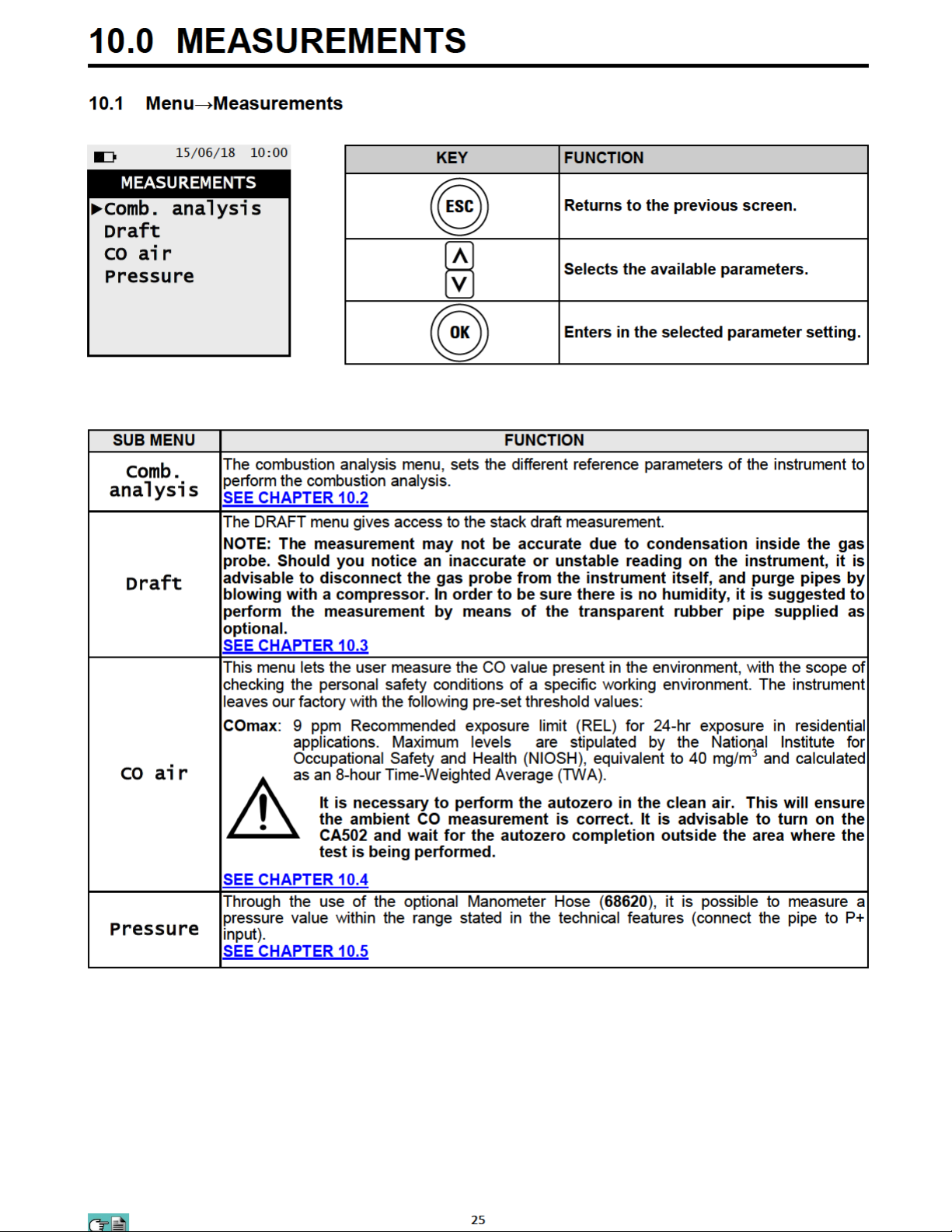
Page 26
Page 27
Page 28
Page 29
Page 30
Page 31
Page 32
Page 33
Page 34
Page 35
Page 36
Page 37
Page 38
Page 39
Page 40
Page 41
Page 42
Page 43
Page 44
Page 45
Page 46
Page 47
Page 48
Page 49
Page 50
Page 51
Page 52
Page 53
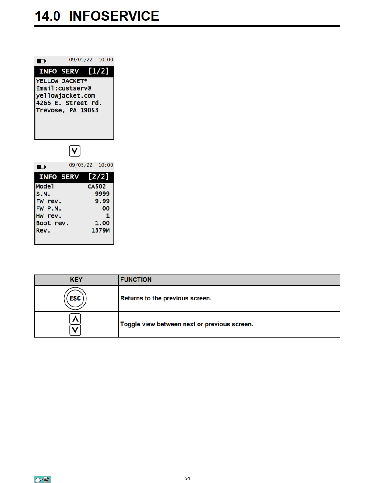
Page 54
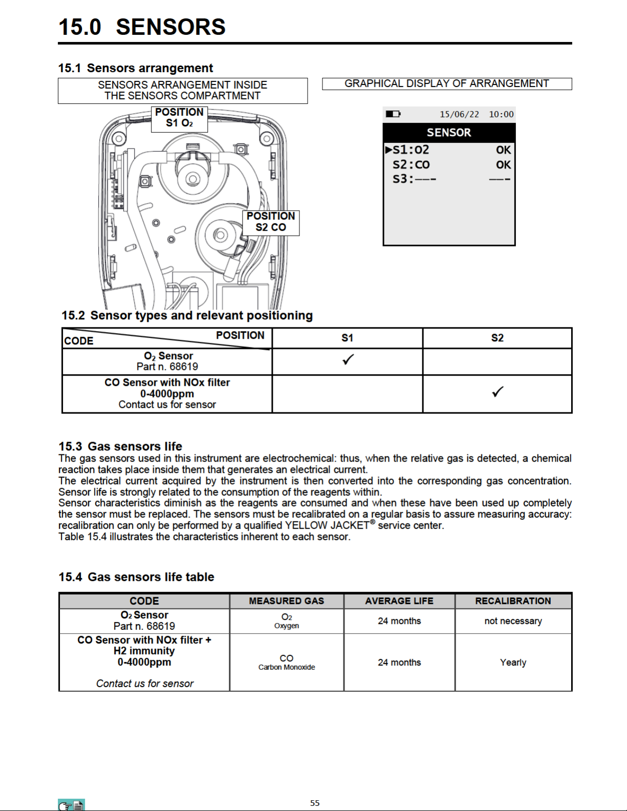
Page 55
Page 56

16.0 MAINTENANCE
16.1 Routine maintenance
This instrument was designed and manufactured using top-quality components. Proper and systematic
maintenance will prevent the onset of malfunctions and will increase instrument life altogether.
The following basic requisites are to be respected:
• When the analysis is over remove the sample probe from the stack and let the analyzer draw fresh air for a
few minutes, or at least until the displayed parameters return to their original values:
O2: >20.0%
Toxic gases: <20ppm
• Clean the filter unit when necessary, replacing the particulate filter and applying a jet of air to the sample
probe hose to eliminate any condensate that may have formed.
Do not clean the instrument with abrasive cleaners, thinners or other similar detergents.
16.2 Preventive maintenance
At least once a year send the instrument to the Yellow Jacket service center for a complete overhaul and
thorough internal cleaning.
YELLOW JACKET® highly qualified staff is always at your disposal and will provide you with all the sales,
technical, application and maintenance details required.
The service centre will always return the instrument to you as new and in the shortest time possible. Calibration is
performed using gases and instruments comparable with National and International Specimens. Annual servicing
is accompanied by a specific calibration certificate that is a guarantee of perfect instrument performance, and it is
indispensable for users wishing to maintain ISO 9000 status.
56
Page 57
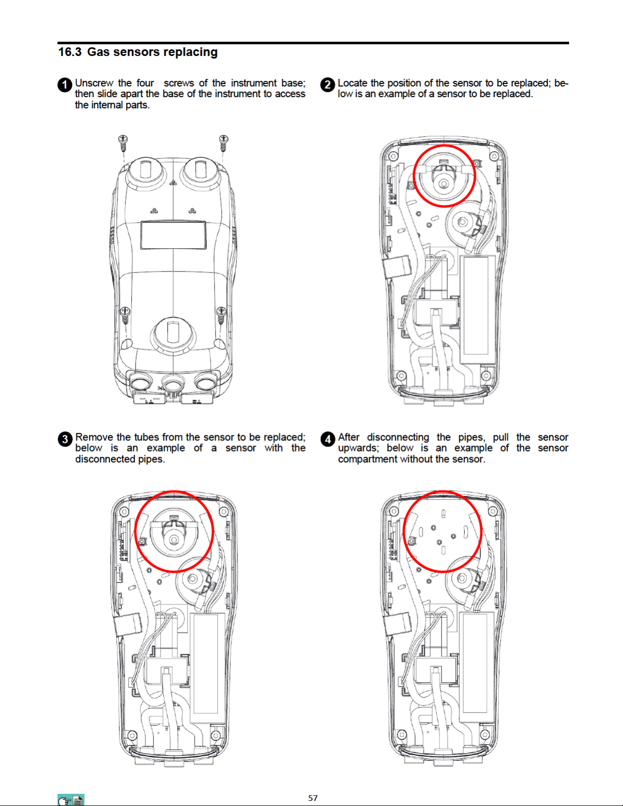
Page 58
Insert the new sensor paying attention to match the sensor connectors with the relevant supports on the
5
circuit board.
Place back the tubes (See point 4).
6
Close back the base of the instrument and screw back the four screws (See point 2).
7
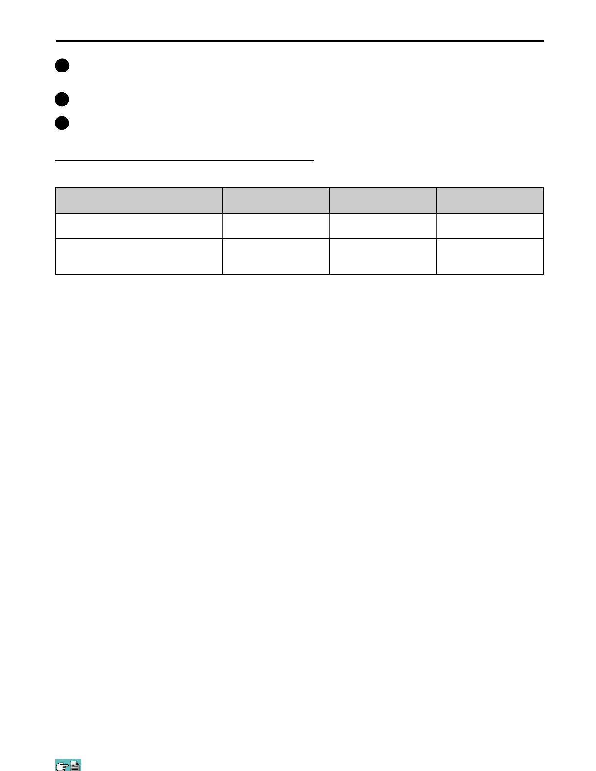
Turn on the instrument to check the new sensor works correctly through the menu "Sensor Troubleshooting".
It is normal if a newly installed sensor gives a 'current error': it is necessary to wait some time, so that the sensor
polarization can settle.
The table here below shows the minimum settling time for each sensor.
CODE DETECTED GAS POSITION SETTLING TIME
O2 Sensor
P/N 68619
CO Sensor with NOx filter
0-4000ppm
O2
Oxygen
CO
Carbon Monoxide
S1 8 hours
S2 2 hours
58
Page 59
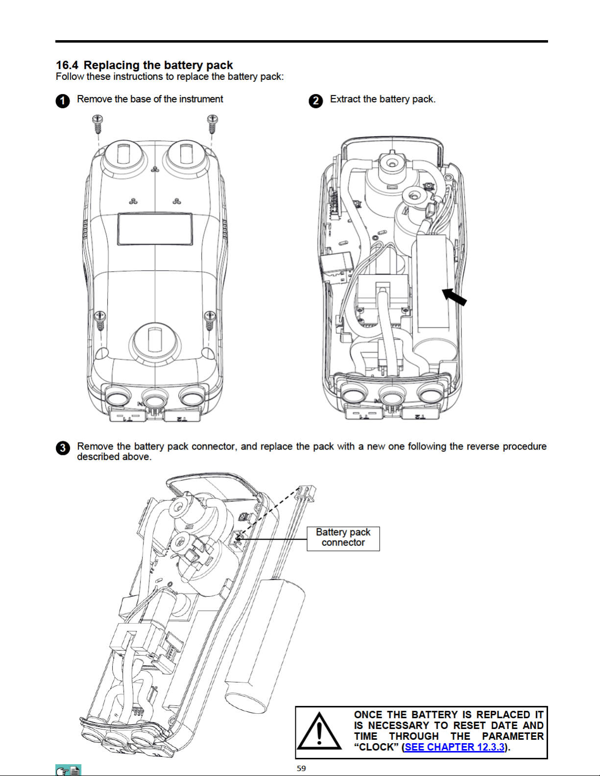
Page 60
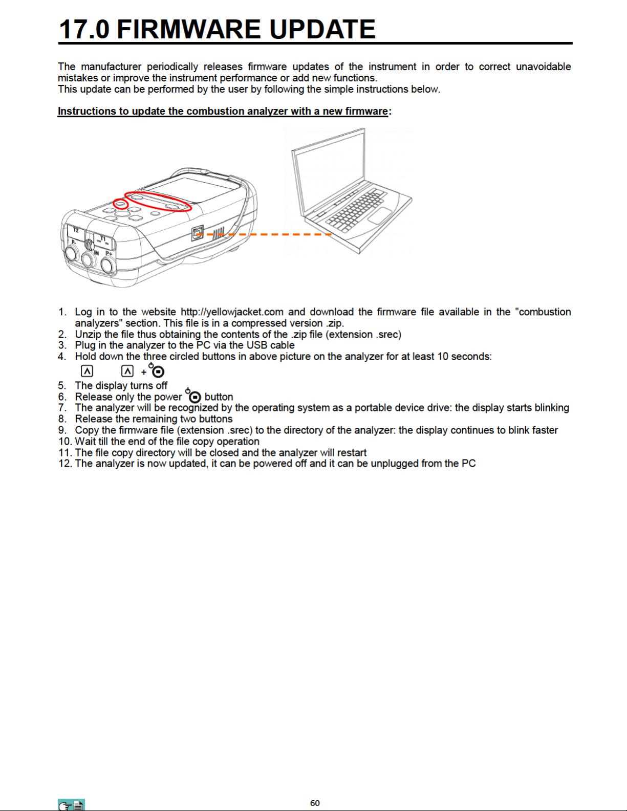
Page 61

18.0 TROUBLESHOOTING
1 .1 Troubleshooting guide 18.1 Troubleshooting guide
SYMPTOM PROBABLE CAUSES AND REMEDIES
a. Press the for at least 2 seconds.
b. The battery is low; connect the battery charger to the
instrument.
The instrument does not work at all. Pushing the
button the instrument does not turn on.
The battery symbol is empty on the inside and blinking.
The instrument battery performance is lower than what
stated in the “Technical features” chapter.
c. The battery pack is not connected to the instrument.
Access the internal parts of the instrument and verify
that the connector of the battery pack is inserted in
the proper connector (SEE CHAPTER 16.4).
d. The instrument is faulty: send it to a service center.
The batteries are low. The instrument will remain on for
a couple of minutes after which it will switch off;
connect the battery charger.
a. The battery capacity is limited at a low temperature.
To obtain a greater performance it is advised to
keep the instrument in higher temperatures.
b. Perform a 100% complete charge cycle connecting
the instrument to the plug for at least 6 hrs.
c. That battery pack is old. Aging can cause the
batteries to reduce their capacity. If the performance
has become unacceptable change the internal
battery with an original part Yellow Jacket.(68623)
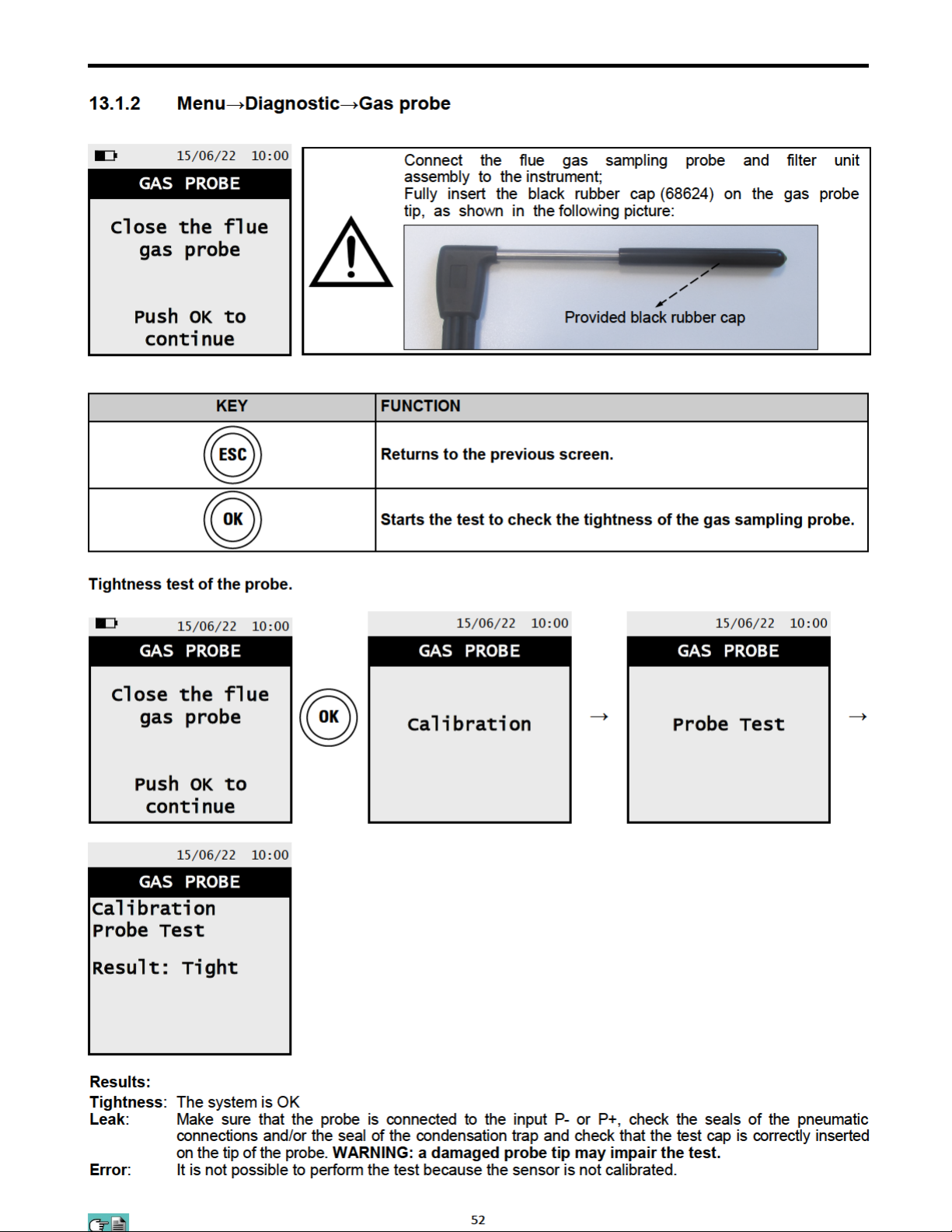
d. Verify the measured voltage values in
“Menu→Diagnostic→Hardware→Voltages”:
- If VBAT<3000mV: the battery needs to be changed.
- If VIN <4700mV: the output voltage of the battery
charger is not sufficient to recharge the instrument
battery. In this case verify the connections and the
plate data of the battery charger in use: 5Vdc 2A.
d. If the problem keeps on happening contact the
SERVICE CENTER.
Date and time are not memorized.
After the autozero, the sensor diagnostic screen
appears, which indicates an error in one or more cells.
In the Pressure / Draft screen there is an error of the
pressure sensor.
In the analysis screen there is an error in the smoke
temperature measurement (Tf).
a. Verify the voltage value VRTC showed in
“Menu→Diagnostic→Hardware→Voltages”:
If <2600mV contact the SERVICE CENTER.
b. The battery is completely drained (VBAT<2500mV)
a. The autozero has been performed while the
combustion gas sample was still being taken.
b. The O2 sensor is broken, incorrectly connected or
not connected at all. Check the described points,
with the help of the paragraph 5.3, 5.4, 6.6.
c. The waited settling time of the sensor was not
enough or the instrument has been left with a low
battery charge for a long time.
There is a calibration problem.
Send the instrument to the service center.
a. Thermocouple not connected; connect the
thermocouple to the analyzer.
b. The sensor has been exposed to temperature higher
or lower than its functioning.
c. The thermocouple is faulty. Send the entire probe to
the service center.
61
Page 62

Troubleshooting guide Troubleshooting guide
SYMPTOM PROBABLE CAUSES AND REMEDIES
The following symbol "----" appears on the analysis
screen.
"Max. Lim." or "Min. Lim" appears on the analysis
screen.
The sample pump sounds as though it is running
slowly, tends to stop or does not even start.
The back lighting of the display does not turn on. The instrument is faulty. Send it to the service center
The values shown in the analysis screen are not
reliable.
The instrument is not able to calculate a numerical
value based on the flue gas analysis conducted. The
"----" are replaced by numbers when the analyzer
detects valid combustion data.
The relative sensor is detecting a value that is beyond
the analyzer measuring range. "Max. Lim" or "Min.
Lim." are replaced by numbers when the instrument
reveals values that are within the measuring range.
a. Sample flow is obstructed. Check that the water filter
is clean and that it is not completely soaked. Also
check that the hose connected to the probe is not
crushed.
b. Sample intake flow is obstructed. Check that the
particulate filter is clean.
c. Pump is disabled. The key combination has
been pressed. To re-enable the pump, switch off the
instrument and then switch it on again.
for repairing.
a. Sensor/s is/are faulty. Check that the sensors are
installed correctly by accessing the sensor diagnostics
menu.
b. The sample probe connection presents a leak.
Check all joints and the conditions of the hose.
c. The instrument is faulty: Send it to a service center
for repairing.
>
>
62
Page 63
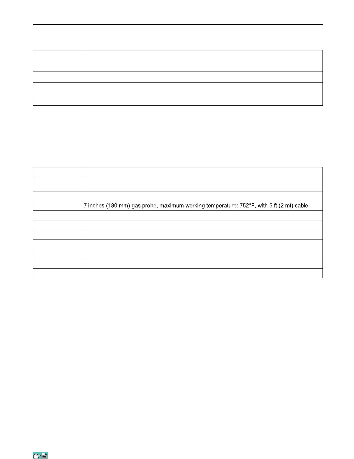
19.0 SPARE PARTS AND SERVICING
19.1 Spare parts
PART NUMBER DESCRIPTION
68612 Replacement particulate filter (5-pack)
68623 Li-Ion 7,2V 2,4Ah battery pack
68619 O2 Sensor Replacement
68616 Printer Paper (5-pack)
19.2 Accessories
PART NUMBER DESCRIPTION
68613
68615 Carrying case
68622
68624 Rubber probe cover
68617 Water trap / filter assembly
68614 Adapter cable USB-A / USB-B
68611 Wireless Bluetooth® printer
68618 O-ring replacement for water trap
68620 Manometer hose
68621 POSG cone for probe
AC Power Adapter Kit For ALL Analyzers (Power adapter w/ US plug adapter + USB A / USB
B cable)
19.3 Service Centers
YELLOW JACKET®
4266 E. Street Rd.
Trevose, PA 19053
Email:[email protected]
WWW.YELLOWJACKET.COM
63
Page 64
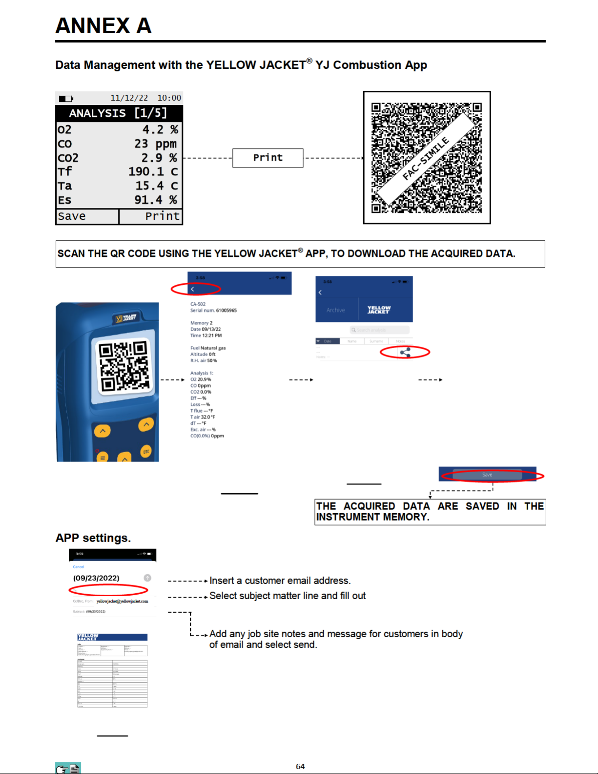
Page 65
Page 66
Page 67
ANNEX C
Coefficients of the Fuels and Formulas
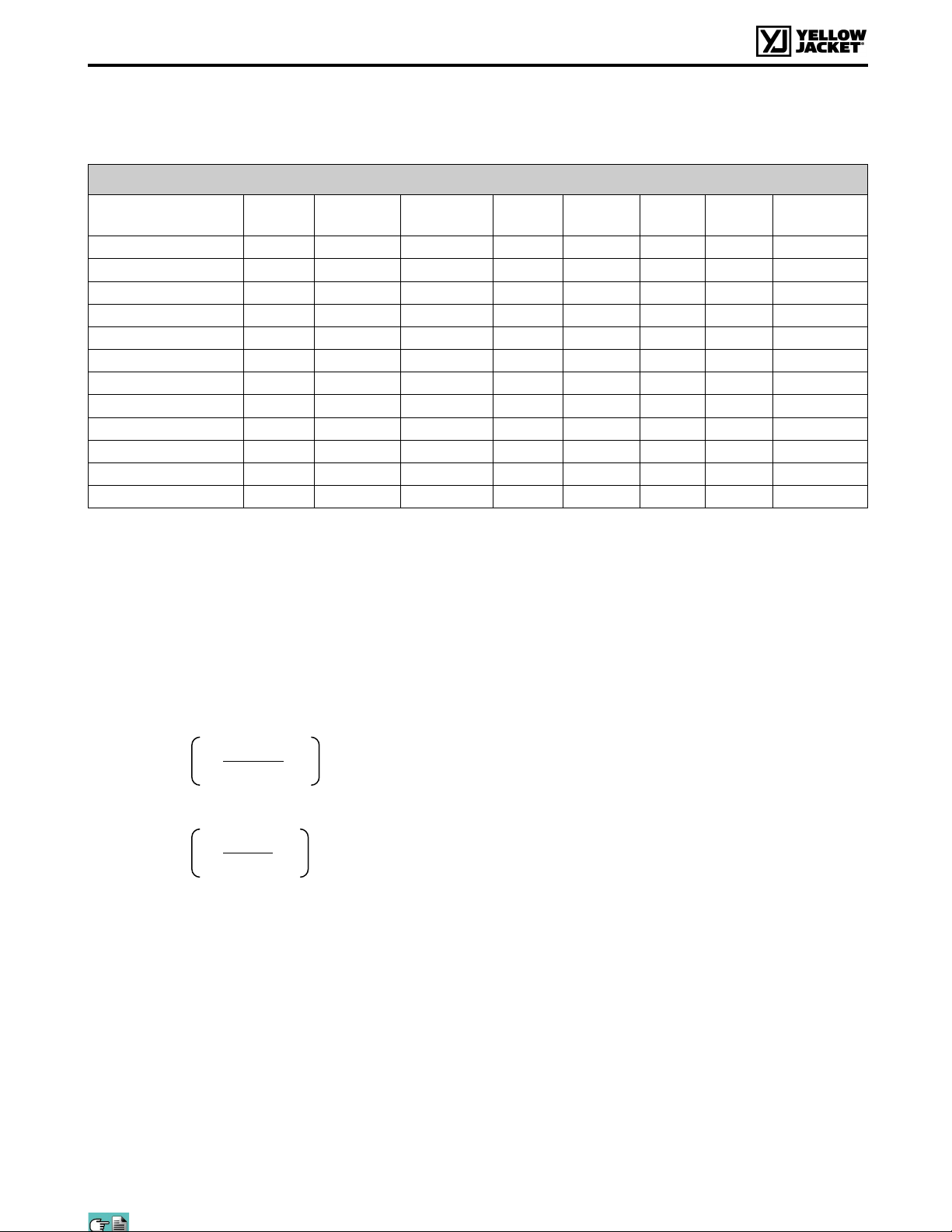
The following chart, lists the coefficients of the memorised fuels, used for calculating losses and efficiencies.
Details of the coefficients of the fuels:
Coefficients for calculating combustion efficiency
Fuel A1 USA B CO2t
(%)
PCI
(KJ/Kg)
PCS
(KJ/Kg)
M air
(Kg/Kg)
M H2O
(Kg/Kg)
V dry gas
(m3/Kg)
Natural Gas 0,0280 0,0090 11,70 50050 55550 17,17 2,250 11,94
Propane 0,0277 0,0073 13,70 45950 49950 15,61 1,638 11,11
#2 Oil 0,0305 0,0066 15,70 42900 45700 14,30 1,136 10,34
#4 Oil 0,0306 0,0066 15,80 41100 43500 13,80 0,973 10,06
#6 Oil 0,0346 0,0048 16,00 39800 42197 13,61 0,981 9,97
Diesel 0,0305 0,0066 15,70 42900 45700 14,30 1,136 10,34
Wood/Pellets 8% 0,0354 0,0071 19,01 18150 19750 6,02 0,660 4,58
Bagasse 0,0395 0,0219 20,45 6950 8834 2,50 0,779 1,93
Coal 0,0320 0,0000 18,60 31400 32300 10,70 0,370 8,14
Biogas 0,0353 0,0091 17,33 17800 19800 6,08 0,830 4,55
Bio-Fuel 5% 0,0305 0,0066 15,70 42600 45400 14,22 1,133 10,64
Butane 0,0277 0,0073 14,00 45360 49150 15,38 1,548 10,99
• CO2 t: The value of CO2 generated by combustion in stoichiometric condition, i.e. without excess Oxygen
and therefore maximum.
• A1, B: Also please have a look at the Siegert formulas from the European standard EN50379-1 (in the
following).
A1 is the parameter in the Siegert Formula when the O2 measurement is available.
NOTE: For the US the A1 parameter is the same as the 'European' A1 BUT divided by 2.
Flue gas heat losses are calculated from measured oxygen content according to the relationship:
Flue gas heat losses are calculated from measured carbon dioxide content according to the relationship:
qA = (tA - tL) x
A1
21
21 - O2
+ B
• CO conv: Conversion coefficient from ppm to mg/KWh. It can be expressed as a function of the gas density
CO2t
qA = (tA - tL) x
A1
CO2
+ B
Air index is calculated with the formula:
λ=21/(21-O2), where O2 is the oxygen residual concentration in the combustion smokes.
Air excess is calculated with the formula:
e=(λ-1)*100
(CO in this case) and the volume of the dry smoke.
• NO conv: Same as CO conv, but for NO.
• NOx conv: Same as CO conv, but for NOx.
• SO2 conv: Same as CO conv, but for SO2.
• PCI: Potere Calorifico Inferiore. Italian for LHV (Lower Heating Value).
• PCS: Potere Calorifico Superiore. Italian for HHV (Higher Heating Value).
• m H2O: Mass of the air produced (per each Kg of fuel) in the combustion in stoichiometric condition.
• m Air: Mass of the air needed for combustion in stoichiometric condition.
• V g.d.: Volume of dry smokes produced in the combustion.
67
Page 68

WARRANTY CERTIFICATE
WARRANTY
The CA502 flue gas analyzer is guaranteed for 12 months from purchasing document date including the
electronic parts, the internal electro-chemical sensors. .
YELLOW JACKET® undertakes to repair or replace, free of charge, those parts that, in its opinion, are
found to be faulty during the warranty period. The products which are found defective during the above
mentioned periods of time have to be delivered to YELLOW JACKET
following cases are not covered by this warranty: accidental breakage due to transport, inappropriate use
or use that does not comply with the indications in the product’s instruction manual or quick start guide.
Any mistreatment, repairs and modifications to the product not explicitly authorized by YELLOW JACKET
shall invalidate the present warranty.
IMPORTANT
For the product to be repaired under Warranty, please send a copy of this Certificate along with the
instrument to be repaired, together with a brief explanation of the fault observed.
Space reserved for user
®
Laboratories postage paid. The
®
Name:
Company:
User’s notes:
Date: ________ Serial Number
Test Equipment Depot - 800.517.8431
- 5 Commonwealth Ave, MA 01801 - TestEquipmentDepot.com
 Loading...