

Page 1
99 Washington Street
Melrose, MA 02176
Phone 781-665-1400
Toll Free 1-800-517-8431
Visit us at www.TestEquipmentDepot.com
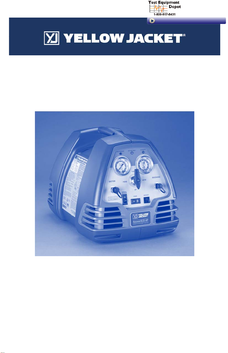
RecoverXLT2-AP™ Oil-Less Universal
Refrigerant Recovery System
Operation and Maintenance
Manual
(English)
Page 2

Table of Contents Page
General Safety Instructions 2-3
RecoverXLT2-AP
S
ystem Purge Instructions
Restart
Pr
Push-
Pull Liquid Recovery
ing R-410A High Pressure Gas 6
Recover
Suction
Filter 7
y Tips & T
Recover
T
roubleshooting
L
ED Light Me
T
echnical Data
Calculated
RecoverXLT2-AP
portant Notice to Purc
Im
arranty Information
W
Operation
Dir
ect Liquid Recovery
Recovery
Vapor
ocedure 5
echniques 7
Guide 8
aning 8
Recovery Ra
Wiring Diagram
Guide
3-4
4
5
5-6
9
tings 9
9
haser 10
10
General Safety Instructions
1) Know your equipment. Read and understand the
operation manual and the labels affixed to this
unit. Learn the applications and limitations, as
well as the specific potential hazards of the
RecoverXLT2-AP .
2) Use the correct hoses. Use only hoses designed
for handling of refrigerants. Th
the
minimum length required for each job and
equipped with a shut-off device (s
co
mpact ball valve) at the
likelihood o
For best performance we recommend using 3/8”
hoses. YELLOW JACKET hoses are made for
almost every type of refrigerant. See your local
distributor for more information.
3) Ground
RecoverXLT2-AP
tacle using the appropriate plug.
4) If the detachable power cord is damaged, it
must be replaced by a cord assembly available
from the manufacturer or distributor wher
purchased.
5) If the
must be replaced by the manufacturer or
authorized service
6) Do not pressure test with compressed air. Some
mixtures of air and refrigerant have been shown to
f refrigerant leaks to the atmosphere.
all equipment. Plug th
into a properly grounded recep-
attached power socket is damaged, it
center in order to avoid hazard.
e hose should be
uch as the
end to reduce the
e
e
its
2
be combustible at elevated pressures.
7) Avoid dangerous environments. To keep
operator exposure to a minimum,
RecoverXLT2-AP
ventilation.
8) Recovery should always be performed in well
ventilated areas. Use the RecoverXLT2-AP only
in locations where mechanical ventilation which
provides at least four air changes per hour
esent, or place the unit 18” above the floor
pr
during use.
9)The RecoverXLT2-AP should not be used near
open containers of gasoline or any other flammable liquid. Do not allow refrigerants to come in
contact with open flame. Refrigerant decomposition in flame results in phosgene gas. Br
ne gas can be fatal.
phosge
10) Always wear safety goggles and gloves. Personal protective equipment should be worn to protect
operator from frostbite.
11) Use caution when connecting or disconnecting.
Improper usage may result in refrigerant bur
(f
rostbite). If a major leak occurs, proceed imme-
diately to a well ventilated area.
12)
Disconnect recovery machine from pow
before servicing.
present when the unit is disassembled.
only in areas with sufficient
An electrical shock hazard is
use the
is
eathing
ns
er
Page 3

13. Repair damaged parts. Do not operate the
RecoverXLT2-AP if there is a defective part.
Repair the unit to proper operating conditions
before further use.
14. Use recommended accessories. Follow the
instructions that accompany all accessories.
Improper use may damage equipment or cr
a hazard.
the RecoverXLT2-AP only with the prop-
Use
15.
er refrigerants. (See specifications for a com-
plete list of compatible refrigerants.)
16. Operate the RecoverXLT2-AP within the
design parameters only. The
RecoverXLT2-AP was designed to operate
within a temperature range of 40
o
120
F (49oC). Do not operate in a wet location.
17. To minimize sparking potential, it is recommended that electrical equipment startup by fi
tur
ning on switch then plug power cord into an
outlet at least three meters away.
o (4o
C) to
18. Use an area fan to vent/diffuse any leakage
during service.
19. Evacuate all air from system/recovery cylinder
prior to use.
20. Fill tank to no more than 45% of HFC safe fill
eate
rst
weight.
L
abel all recovery cylinders appropriately.
21.
22. To minimize sparking potential, locate vacuum
pump outside of building.
Caution: All refrigerant hoses, recovery tanks,
refrigerant lines, other vessels containing refrigerants
and the RecoverXLT2-AP should be handled as if
under high pressure. When opening a tank containing
refrigerant, open valves slowly to prevent release of
refrigerant, especially if the valves might be
damaged.
To prevent the risk of fire DO NOT use an extension
cord longer than 25’ (7.6 m) and a minimum of 16
AWG (1.276 mm
RecoverXLT2-AP Operating Guide
Direct Liquid/Vapor Recovery
2
).
The RecoverXLT2-AP is used to pull liquid or vapor
refrigerant out of the system and transfer it into a
recovery cylinder.
Liquid recovery is accomplished by connecting to
the high pressure system discharge service port
(liquid port) side of the system being serviced with a
manifold (to regulate refrigerant flow).
Vapor recovery can be done by connecting to the
system suction service port (low pressure) side of
the system.
Because the RecoverXLT2-AP is capable of recov-
ering liquid, it is more efficient to recover all of the
liquid, followed by the vapor.
Ensure you have the capacity to recover all the refrigerant in the system. In the USA the recovery
cylinders can only be filled to 80% capacity and in
the EU it is only 60% capacity and 45% for HFCs.
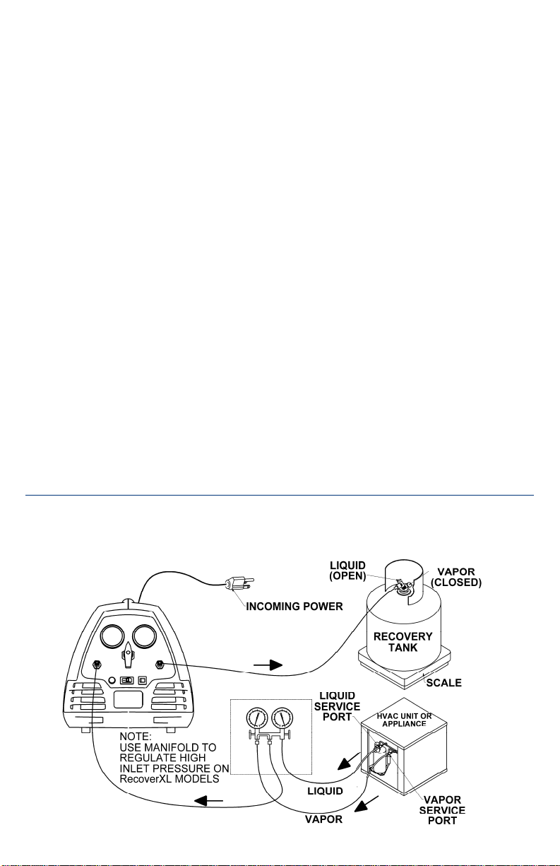
Refer to the following instructions and the diagram
on page 4:
Liquid Recovery
1. Know the type and quantity of refrigerant present before servicing any system.
2. Turn off power to the system being serviced.
Turn the selector knob to off.
3. Connect your manifold to the system
ser
viced. High Side to liquid port and Low Side
to vapor port as shown in diagram on page 4.
4. Connect the Utility port of your manifold to the
1/4” SUCTION port of the RecoverXLT2-AP
Connect one hose from the recovery cylinder
5.
(liquid side) to the 1/4” DISCHARGE port of
the RecoverXLT2-AP
Note: Be
sure to connect hose ends with shutoff to suction and discharge ports of recovery
machine. (For best performance us
hoses.)
6. Purge all hoses of non-
recovering refrigerant into recovery cylinder.
7. Open the liquid valve on the recovery tank.
8. Turn the selector VALVE on th
RecoverXLT2-AP to LIQUID RECOVERY
position.
9. Open the High Side and Utility valves on your
manifold and use them to regulate the refrigerant pressure to 80 psi maximum.
10. Ensure ambient pressure by
rect position based on if this feature is being
cor
used.
.
condensables before
pass switch is in the
being
e 3/8”
e
.
3
Page 4
11. Turn the RecoverXLT2-AP on.
Note: The RecoverXLT2-AP will turn
r
un for approx. six seconds before the compressor will start. This is to ventilate the enclosure
and prevent potentially dangerous mixtures of
gasses building up inside the unit.
12.
T
he RecoverXLT2-AP will recover the liquid
refrigerant. When you have removed all
liquid in the sy
procedure step 9 to reduce your recovery time
Vapor Recovery
1.
Know the type and quantity of refrigerant present before servicing any system.
2. Turn off power to the system being serviced.
Turn the selector knob to off.
3. Connect your manifold to the system
serviced. High Side to liquid port and Low Side
to vapor port as shown in diagram on page 4.
4. Connect the Utility port of your manifold to the
1/4” SUCTION port of the RecoverXLT2-AP
Connect one hose from the recovery cylinder
5.
(liquid side) to the 1/4” DISCHARGE port of
the RecoverXLT2-AP
Note: Be
off to suction and discharge ports of recovery
machine. (For best performance us
hoses.)
stem switch to vapor recovery
.
sure to connect hose ends with shut-
on and
the
being
e 3/8”
6. Purge all hoses of non-
recovering refrigerant into recovery cylinder.
7. Open the liquid valve on the recovery tank.
8. Turn the selector VALVE on the RecoverXLT2-
AP to VAPOR RE
Slowly open the valves on your ma
9.
use the
m to regulate the refrigerant pressure to
80 psi maximum.
.
.
T
urn the RecoverXLT2-AP on.
10.
Note: The RecoverXLT2-AP will turn on and
run for approximately six seconds before
co
mpressor will start. This is the ventilate the
enclosure and prevent potentially danger
m
ixture of gasses from building up inside the
unit.
he RecoverXLT2-AP will recover the vapor
11. T
refrigerant. When the suction gauge indicates
the appropriate vacuum, turn the selector valve
OFF.
Turn selector valve to PURGE position.
12.
13. When the suction gauge again indicates the
appropriate vacuum the recovery and pur
cycles
are complete. Turn the selector valve to
OFF and turn the RecoverXLT2-AP off.
Note: If the machine is not recovering, refer
to the troubleshooting guide on page 9.
Restart procedures are on the side of the
machine and on page 5.
condensables before
COVERY position.
nifold and
the
ous
ge
Liquid or Vapor Recovery Diagram
4
Page 5

System Purge Instructions
Purging or evacuating the RecoverXLT2-AP is one
of the simplest and most important functions. Reduce the risk of cross contamination and prolong the
life of the RecoverXLT2-AP by purging after every
service.
Note: The purge process must be done before
disconnecting the discharge hose from the
RecoverXLT2-AP.
1. Once the unit reaches appropriate vacuum level,
either at just above ambient pressure with the
ambient pressure switch or user defined vacuum
Restart Procedure
If the recovery unit was stopped during operation,
it may be necessary to balance the internal
pressures before the unit will start.
To balance the internal pressure:
1) Turn the system switch off.
Push-Pull Liquid Recovery
level, turn the system switch to OFF, then rotate
the selector valve clockwise first to OFF the
equalize then to PURGE. Turn the system
switch ON.
Note: The low side gauge should read an
increase in suction pressure, indicating the
refrigerant that was trapped in the machine.
Wait until the low side gauge reaches an
appropriate vacuum.
2. Close the valve to the recovery tank and shut the
RecoverXLT2-AP off.
2) Rotate selector clockwise to the OFF position.
Allow pressures to balance.
3) Turn the selector valve counter-clockwise to
the previous RECOVER position.
4) Turn the recovery machine ON.
The Push-Pull Liquid Recovery mode is used for
transferring large volumes of liquid refrigerant.
The RecoverXLT2-AP “pulls” vapor from the
recovery cylinder and produces high pressure
discharge gas that “pushes” liquid out of the
HVAC system and into the recovery cylinder. The
auto purge feature makes the reconfiguration to
vapor recovery easier and faster to do.
Some HVAC systems will not allow for the pushpull recovery method. If any of the following
conditions apply, do not use push-pull method, but
follow the instructions on page 3.
• System contains less than 10 pounds of
rigerant.
ref
• System is a heat pump or other unit with a
reversing valve.
• System has an accumulator between the
service ports used in liquid recovery.
• The refrigerant system does not allow for the
formation of a solid column of liquid.
For push-pull recovery, a sight glass is monitored
during recovery. When liquid is no longer visible,
stop recovery and finish recovering using the
VAPOR recovery process for RecoverXLT2-AP as
described on page 4.
When push-pull recovery is complete, a small
amount of refrigerant remains in the system. For
complete recovery, the system must be pulled into
a vacuum as required by EPA standards. This
process requires:
1) An extra hose for the push-pull recovery.
2) A recovery cylinder with about 5 lbs.
ref
rigerant.
3) A sight glass (Note: Make sure sight
rated for
being recovered)
Follow these steps:
Turn off power to the system to be serviced.
1)
2) Hook up the RecoverXLT2-AP, the system to
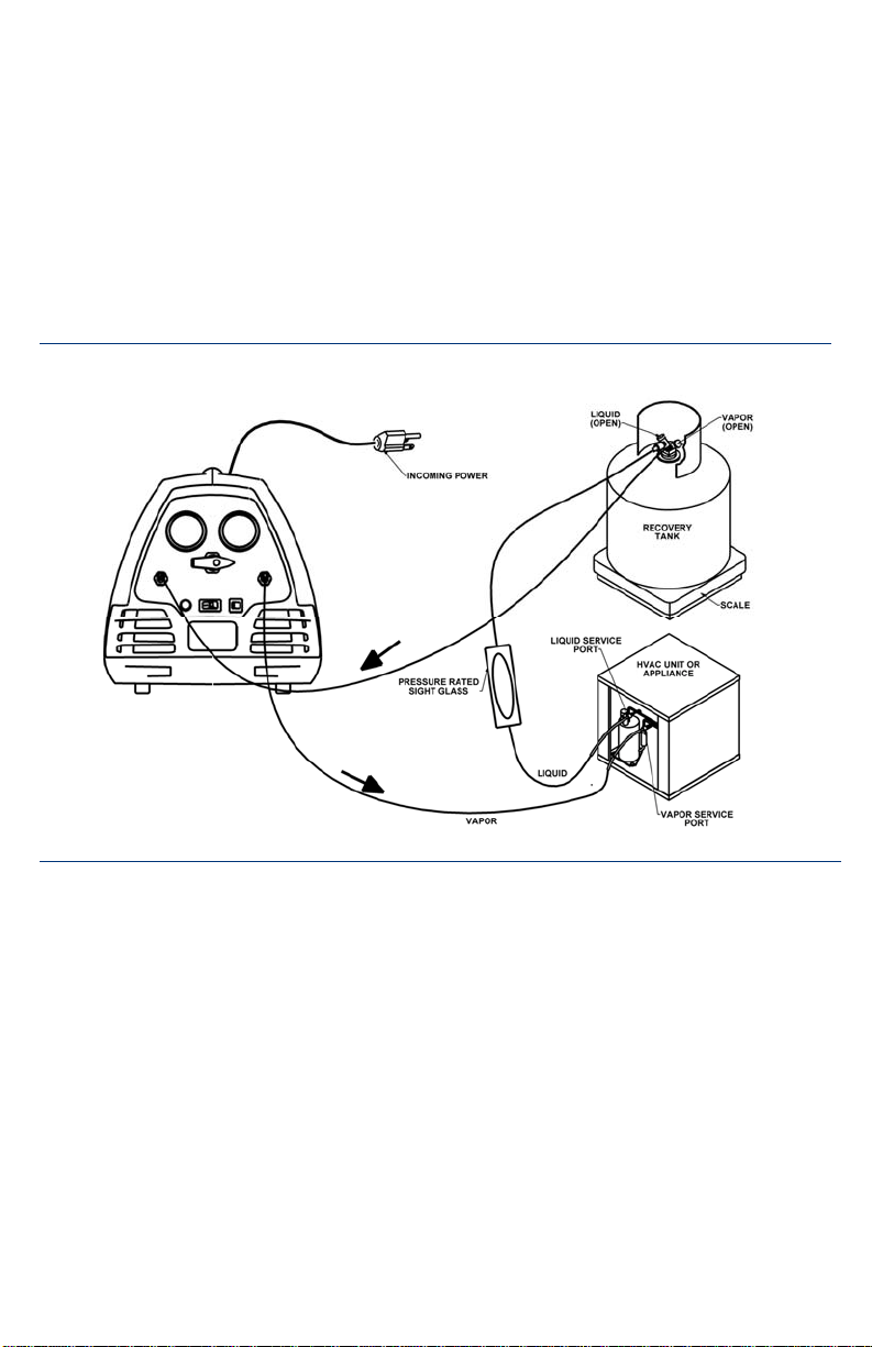
be recovered, and the recovery tank as shown
in the diagram on the next page.
3) Purge all hoses of non-condensables before
recovering refrigerant into recovery cylinder.
4) Open valves on the recovery tank.
5) Turn the selector valve to VAPOR position.
Turn the RecoverXLT2-AP on.
6)
Note: The RecoverXLT2-AP will turn on and
run for approximately six seconds before
co
enclosure and prevent potentially danger
m
unit.
the pressure of the refrigerant
.
mpressor will start. This is the ventilate the
ixture of gasses from building up inside the
of
glass is
the
ous
5
Page 6
7) Monitor the sight glass. When the passing
liquid in no longer visible through the sight
glass, the push-pull method of recovery is
.
complete
8)
Close the VAPOR valve on the recovery tank
and let the recovery continue.
9) Turn the selector valve clockwise to the
PURGE position and follow procedures for
purging the RecoverXLT2-AP
urn the RecoverXLT2-AP off.
10) T
.
Push-Pull Recovery Diagram
11) Close LIQUID valve on recovery tank.
12) Reconnect the hoses per the procedure for the
RecoverXLT2-AP
Rotate the selector valve to the VAPOR
13)
position.
14) Continue
reaches the appropriate level of vacuum.
Note: See pages 3-4 for a detailed set of
instructions on Vapor Recovery.
instructions.
recovery until the unit shuts off or
Recovering R-410A High Pressure Gas
IMPORTANT!!! Some equipment should not be
used with this refrigerant. Take time to read the
safety instructions that came with the device you
are servicing as well as any material that came with
your refrigerant.
WARNING!!! USE ONLY D.O.T. RECOVERY
CYLINDERS APPROVED FOR R-410A.
Overfilling the tank may cause it to rupture!
The RecoverXLT2-AP will recover R-410A
provided the following instructions are followed:
1) Set-up for recovery as per diagram on page 4
for normal recovery or page 5 for pushr
ecovery.
pull
6
2) Follow the operating procedures for y our
model.
3) Continue
cates the appropriate level of vacuum or
Ambient Pressure Switch has shut the unit off
and LEDs indicate Recovery Complete
Turn system switch off.
4)
5) Purge the machine (see page 5 for more
details).
recovery until suction gauge indi-
.
Page 7

Suction Filter
The RecoverXLT2-AP is equipped with a built-in
particulate strainer located behind the suction port.
Unscrew the suction port by using a 11/16 wrench
to unscrew the hex head port to remove. This
prevents contaminants, copper shavings, carbon,
and other foreign objects from making their way to
the RecoverXLT2-AP compressor and causing
permanent damage.
Like a filter drier, this strainer MUST be cleaned
or replaced often. Failure to do this can cause the
strainer to become too clogged for refrigerant to
RECOVERY TIPS AND TECHNIQUES
1) To assure the fastest and quickest recovery
possible, use the shortest hoses possible and
avoid hoses with Schrader depressors.
2) Know what kind and the am
refrigerant that is g
is critical to avoid contamination and
how m
uch refrigerant will be recovered.
st job of the day usually means a fresh,
fir
empty tank and no cause for worry about over
-filling. However, the last job of the day
means there is already liquid in the tank and
over-filling can be a concern. Over-filling a
recovery cylinder can have disastrous results.
3) Always try to recover liquid first. This is the
preferred method of recovery for
RecoverXLT2-AP
tim
es faster in standard liquid mode than
vapor.
4) If recovering large amounts of refrigerant (
more), the push-pull method is recom-
lbs or
mended. (Note: This process requires the
hoses to be switched before recovery of the
remaining vapor.)
, which pump
ount of
oing to be recovered. This
know
The
the
s liquid 5 to 7
20
flow freely. A sure sign that the straining device is
clogged is the freezing of the suction port and the
filter cover.
Before replacing, check the condition of the o-ring.
Replace if necessary.
Note: Make sure to use a strainer in the
RecoverXLT2-AP for every job! Filter strainers
and o-rings are available from your supplier.
Filter Strainer and O-Ring - Part #95457
5) Recovery can often be speeded up by
simultaneous recovery from
low side of the sy
both the high and low side of the system and
join them with a BRUTE™ II Manifold or Y
connector to the hose going to the Suction
Port of the RecoverXLT2-AP.
6) Protect
7) Recovery machines are not vacuum pumps.
the RecoverXLT2-AP by keeping the
built-in suction filter IN THE MACHINE.
Failure to use the suction
RecoverXLT2-AP
For proper evacuation, use a YELLOW
JACKET SuperEvac™ vacuum pump. To
speed up the evacuation process, use the
SuperEvac vacuum pump and a core removal
tool (Part #18975). For more inform
contact your Y
stem. Attach short hoses to
ELLOW JACKET wholesaler.
both the high and
filter in the
will void the warranty.
ation
7
Page 8
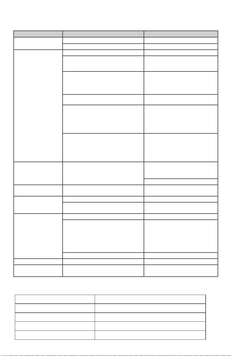
Troubleshooting Guide
Condition
No power to unit
Compressor will not
start
Unit runs but shuts off
after short time
Unit trips breaker upon
start up
Unit runs but does not
recover refrigerant
Unit will not pull a
vacuum
Unit running sluggish Low voltage to unit Check power supply
Vacuum switch won’t
reset
Power cord not plugged in Plug power cord in
Outlet not energized Reset breaker
Compressor under unequalled conditions See restart procedure
Compressor thermal overload is tripped Thermal overload will reset in approx.
Unit is shut down on Recovery
Complete.
Ambient Pressure Switch tripped Pressurize inlet port before power up.
Unit has not ventilated the cabinet yet The RecoverXLT2-AP fan will run for
Unit is shut down on tank full or high
pressure.
Restriction on discharge side tripping the
high pressure switch
Compressor is under unequalled
conditions
Suction filter clogged
Selector valve in wrong position Put selector valve in liquid or vapor
Hoses are not tight Tighten hoses
Ambient Pressure Switch turned off The RecoverXLT2-AP is equipped
Leak in HVAC/R system Find and repair leak in system
Switch needs to reset Pressurize inlet port
Possible Problem Possible Solution
15-30 minutes
Low pressure switch resets at
atmospheric pressure, rotate selector
valve to either the Vapor or Liquid
Recovery position.
approximately six seconds before the
compressor starts up to prevent unwanted mixtures of gas from building
up inside the unit.
Check tank pressure, check for
restrictions, check shorting cap or
umbilical connection, and check high
gauge pressure to see if unit is under
high pressure.
Check for restrictions
1) Tank valves
2
) Schrader cores
Selector valve in correct position
See restart procedure
Clean or replace suction filter
recovery position
with an Ambient Pressure Switch that
will prevent the unit from recovering
below ambient pressure so as not to
pull air into the recovery cylinder from
a potentially leaking system.
LED LIGHT MEANINGS
Green Light Flashing System startup ventilation.
Solid Green Light System Recovering
Solid Yellow Light System loss in airflow detected. Check system fan.
Alternating Red and Yellow Lights Ambient Pressure reached.
Solid Red Light High pressure cutout reached.
8
Page 9
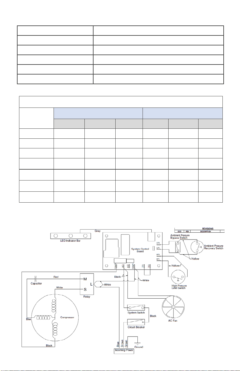
Technical Data
Compressor:
Power Source:
Size:
Vapor Push/Pull Liquid Vapor Push/Pull Liquid
R-22
R-32
R-134a
R-404A
0.17 4.16 3.10 10 250 186
.011 3.41 2.53 7 205 152
0.20 4.20 3.14 12 252 188
0.30 3.66 2.73 18 220 164
1/2 HP Reciprocating Oil-Less
230V AC 50/60 H
Height: 12.50”
i
dth: 12.50”
W
Depth: 19.25”
Weight: 29.90”
z 1 Phase
Calculated Recovery Ratings
Kg./minute Kg./hour
R-410A
R-1234yf
R-407C
0.18 3.70 2.77 11 222 166
0.17 3.83 2.86 10 230 171
0.18 3.99 2.98 11 240 179
Wiring Diagram
9
Page 10

IMPORTANT NOTICE TO PURCHASER
Check for damage immediately. Prior to
shipment, all YELLOW JACKET
RecoverXLT2-AP Refrigerant Recovery
Systems are completely tested and inspected to
assure compliance with Ritchie Engineering factory specifications.
If the recovery system carton is damaged, check
contents immediately. Note damage on shipper’s
Bill of Lading and have shipper sign statement.
Notify carrier immediately of the damage to
arrange inspection of the recovery system and
packaging. The CARRIER ALONE is responsible
for handling and settling your claim. Ritchie
Engineering will cooperate in assessing damage if
the recovery system is returned to the factory
prepaid.
WARRANTY INFORMATION
Ritchie Engineering guarantees YELLOW
JACKET products to be free of defective material
and workmanship which could affect the life of the
product when used for the purpose for which it
was designed. Warranty does not cover items that
have been altered, abused or returned solely in
need of field service maintenance.
YELLOW JACKET recovery products (UPC
957xx) are covered by a one year warranty for
parts and labor.
The following exceptions will not be covered
under this warranty: Recovery products that have
been altered, misused, or improperly maintained.
Carton contents include:
• RecoverXLT2-AP Refrigerant Recovery
System
• Owner’s manual
• Warranty registration card
To validate warranty, mail registration card
within 10 days.
The following must be done before returning
unit:
1) Call our technical service pers
(
800) 769-8370 to assess if the problem
esolved over the phone.
be r
2) Obtain an RGA number from Ritchie
Engineering for the return of the product.
3) Fax a copy of the or
(
800) 322-8684.
If at any time after the warranty period you
have problems with your YELLOW JACKET
recovery unit, call our technical service department for help in selecting the correct replacement parts, or to arrange for its repair at reasonable costs.
iginal invoice to
onnel at
can
10
Test Equipment Depot - 800.517.8431 - 99 Washington Street Melrose, MA 02176
TestEquipmentDepot.com
 Loading...