

Page 1
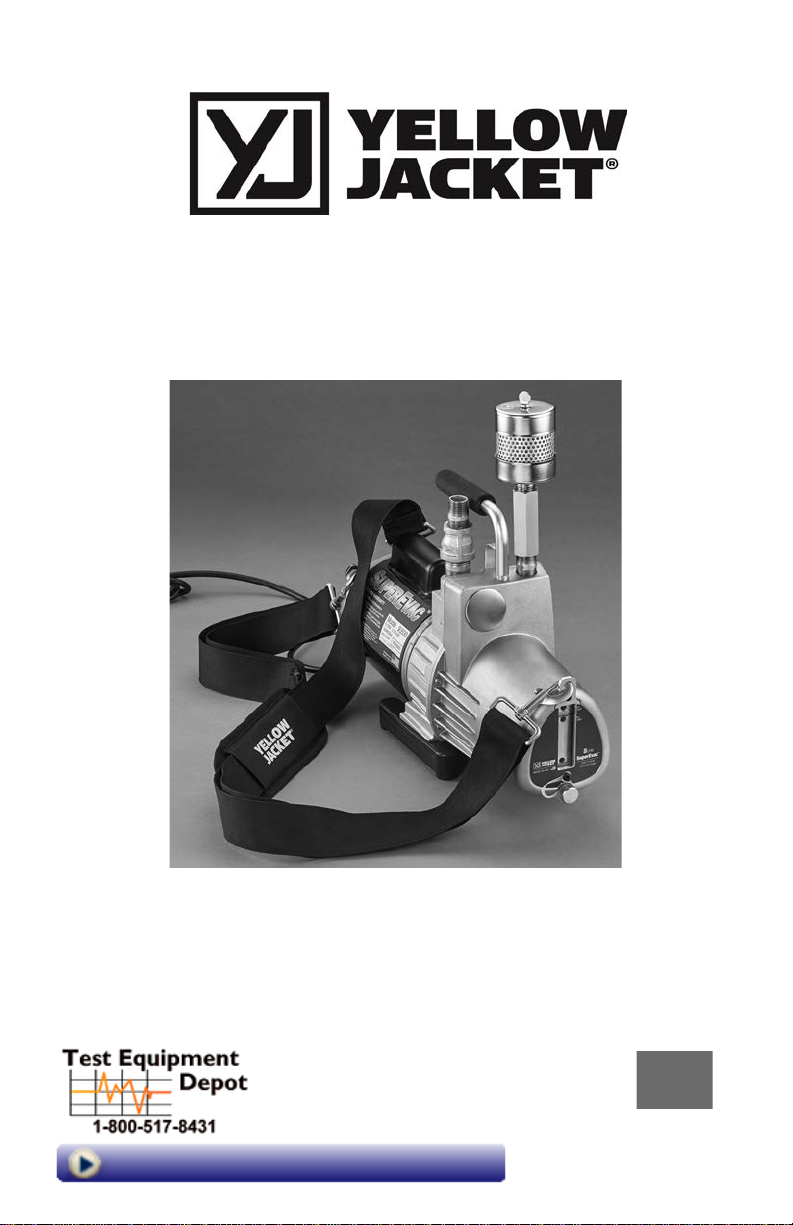
SuperEvac™ Vacuum Pump
for Ammonia and NH3 Systems
Operation and Maintenance
Manual
Models: 93530, 93533, 93539
99 Washington Street
Melrose, MA 02176
Phone 781-665-1400
Toll Free 1-800-517-8431
Visit us at www.TestEquipmentDepot.com
PN 142884 Rev.D 6/19
Page 2
Table of Contents Page
How to obtain service…………………...…………………………………………………………..…….. 2
Features of your new pump.......................................................................................................................... 3
Warranty Information………………………………………………………………...…...………………..3
The purpose of the SuperEvac™ design........................................................................................................4
The 7 important steps of initial start-up........................................................................................................4
Oil changes……………………………………………………………………………………...….…...… 5
Vacuum tips for best performance............................................................................................................... 5
Dual voltage motor power conversion (if applicable)…………………………….………………………..5
Basic troubleshooting................................................................................................................................... 6
Diagnostic chart........................................................................................................................................ 7, 8
Replacement parts..................................................................................................................................... 8, 9
Important Notices to Purchaser
Check for damage immediately.
All YELLOW JACKET SuperEvac™ vacuum
pumps for ammonia and NH3 systems are completely
tested and inspected to assure compliance with
Ritchie factory specifications prior to shipment.
If the pump carton is damaged, check contents im-
mediately. Note damage on shipper's Bill of Lading
and have shipper sign your statement. Notify the
carrier immediately of the damage to arrange inspection of the pump and packaging.
The CARRIER ALONE is responsible for handling
and settling your claim. Ritchie Engineering will
cooperate in assessing damage if the pump is re-
turned to the factory prepaid.
Carton contents include:
SuperEvac
NH3 Systems.
™
Vacuum Pump for Ammonia and
Bottle of YELLOW JACKET
Pump Oil
Owner's manual
®
SuperEvac™
How to Obtain Service
Most returned pumps are merely in need of normal
field service maintenance, such as changing oil or
making minor adjustments. In many instances, the
troubleshooting information in this manual can save
you the time and effort of returning your pump.
When the information contained in this manual,
however, does not solve the problem, please call for
service.
In the U.S. call the Ritchie Engineering Customer
Service Department:
Phone: (952) 943-1333 or (800) 769-8370
Fax: (952) 943-1605 or (800) 322-8684
E-mail: [email protected]
2
A representative will help to determine if the problem can be solved without sending your pump to the
factory and taking it out of service.
Returns: If the pump does need to be returned to
the factory, and you are in the U.S., DRAIN THE
OIL and send the pump - freight prepaid - to:
Ritchie Engineering Company, Inc.
Customer Service Department
10950 Hampshire Avenue South
Bloomington, MN 55438-2623 USA
If you are in a country other than the U.S., please
contact the wholesaler from whom the pump was
purchased.
Page 3
Features of your New Pump
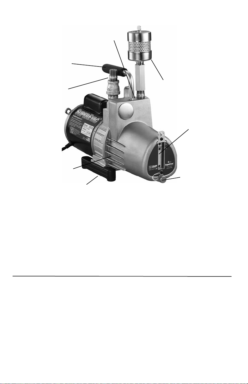
Heavy duty metal handle.
Permanently attached to pump
body. Built-in hook hole.
1) Male pipe
pump intake
(see below)
Heavy duty high
torque motor for
cold weather
starting.
Longer heat dissipation fins for
a cooler running unit.
High resiliency foot pads for
added stability and skid resistance.
1. Male pipe pump intake. Large hose suggested
for maximum pull down.
2. Gas ballast valve helps remove moisture and
other condensable vapors that have been drawn
into the pump as a result of evacuation. Opening
the ballast allows fresh air to enter the pumping
chamber and keep vapors from combining with
the oil. Vapors escape harmlessly through the
2) Gas ballast valve
(see below)
Lower operating temperature to
improve efficiency and vacuum.
Pump exhaust also doubles as oil fill
port. Use YELLOW JACKET
oil for assurance of a
clean,fast job.
Wide-view
sight glass
for easier
Monitoring
of oil level.
Oil drain valve
for quick draining
and convenient access.
exhaust valve. If combined with oil, vapors can
turn the oil milky white and lower pump performance below specifications.
To operate ballast, turn the valve counterclockwise one full turn after evacuation starts.
As the vacuum reading reaches 1000-2000
microns, close the ballast to achieve a deeper
vacuum.
WARRANTY INFORMATION
Ritchie Engineering guarantees YELLOW
JACKET products to be free of defective material
and workmanship which could affect the life of
the product when used for the purpose for which
it was designed. This warranty does not cover
items that have been altered, abused or returned
solely in need of field service maintenance.
If found defective, we will either replace or repair
at our option products within two years of proof
of purchase. Warranty does not cover items that
have been altered, abused (including failure to
use the correct type of vacuum pump oil) or
returned solely in need of field service maintenance. Returns must be pre-paid.
Warranty does not cover use on lithium bromide
systems.
3
Page 4
The Purpose of the SuperEvac Design
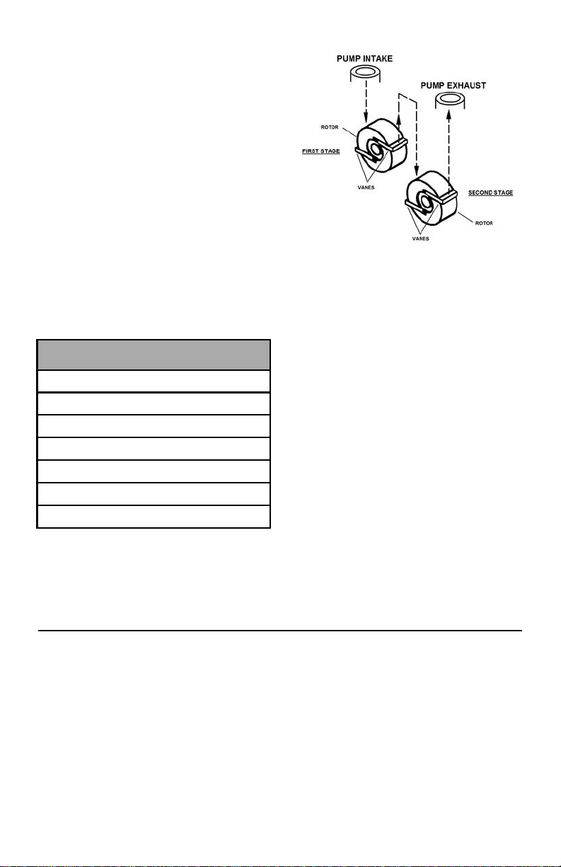
The SuperEvac Pump is a 2-stage rotary vane design
(at right) that increases efficiency and speeds pump
down to 15 microns.
The pump lowers the internal pressure of a refrigeration system until moisture boils into a vapor. As the
moisture is vaporized, it is evacuated by the pump,
helping dehydrate the system. Most technicians try
to achieve between 250 and 1000 microns.
A manometer or electronic vacuum gauge are the
only ways to monitor evacuation progress. Manometer readings are approximate in inches of mercury.
Only an electronic vacuum gauge is accurate enough
to show when you reach the desired micron range.
As the chart shows, only an electronic gauge reads
fine differences to provide assurance that the vacu-
um is low enough to boil the greatest possible
amount of moisture.
How one small drop dampens your profits.
A small drop of moisture can hurt your profits and
reputation.
Boiling temp
of water
212°F (100°C) 0 760,000
151°F (66°C) 22.05 200,000
101°F (38°C) 27.95 50,000
78°F (26°C) 28.95 25,000
35°F (2°C) 29.72 5,000
1°F (17°C) 29.882 1,000
- 50°F (-46°C) 29.919 50
During new system set-up, protective caps are removed admitting moisture and air into system components.
If air – a non-condensable – remains in the system,
it collects on the high side reducing system efficien-
cy. This causes a rise in head pressure. The dis-
Inches
mercury
Microns
First stage exhausts into the intake of the second stage
similar to two single stage pumps connected together.
charge valve gets hotter than normal and organic
solids form causing compressor failure.
Moisture in the system can form ice which closes
off openings in expansion valves and cap tubes, and
prevent adequate cooling.
Ultimately moisture and air can produce acids and
sludge which could cause in-warranty failures.
During service and parts replacement, the same
contaminants get in again, and you could be called
back for repairs by a dissatisfied customer.
Moisture and air can even enter through system
leaks. And as the moisture in the air increases, so
does the amount of contamination. The higher the
humidity, the bigger your problem.
A vacuum pump "pulls" air and moisture out of the
system before the system is damaged. The higher
and more complete the vacuum, the more moisture
is removed. That's why your SuperEvac pump is
specifically engineered for high vacuums of 15
microns and better.
The 7 Important Steps of Initial Start-Up
1) Make sure motor is off and name plate volt-
age on motor bottom matches outlet voltage.
2) Remove exhaust filter. Fill with YELLOW
JACKET SuperEvac Pump Oil until oil level
is even with oil level line. Replace exhaust
filter.
3) With the intake port open, switch on the
motor. When pump reaches running speed,
connect the pump to the system.
4) To check the pump's performance, attach a
5) Improve cold weather starting by opening
6) Before turning pump off, break vacuum to
4
micron gauge to the intake port, making sure
that the gas ballast valve is closed. Turn on
the pump. The micron gauge will display the
ultimate vacuum reached.
intake and running your pump for 10-15
seconds.
atmosphere.
Page 5
7) Disconnect pump and cover the intake to
keep out contaminants.
If an extension cord is needed, refer to the chart
for proper sizing:
Oil Changes
RECOMMENDED EXTENSION
CORD SIZES
Total Extension Cord Length
(Feet)
25' 50' 100'
16 Ga. 14 Ga. 12 Ga.
Wire Gauge (AWG)
CHANGE OIL AFTER EACH USE to protect
pump components from contaminants pulled into
pump during service. Place used oil in a sealable
container and dispose properly in accordance with
local regulations.
YELLOW JACKET vacuum pump oil is specially refined and formulated for extremely low vapor
pressure and high pump efficiency at all temperature conditions. This means it can help you get a
continued return on your pump investment.
Vacuum Tips for Best Performance
1) For the fastest vacuum, connect your pump
directly to the system. Going through a
manifold slows the job.
2) Use as large a hose as possible, even though
the system has 1/4" fittings. A 1/2” or 3/8”
hose allows a much faster and more complete vacuum.
3) Use as short a hose as practical to get maxi-
mum evacuation speed. Short hoses make
evacuation faster than longer hoses. Long
hoses slow the process.
4) Metal hoses are the most impervious so will
be most effective in evacuation.
5) Evacuate through both high and low sides
at the same time to speed evacuation.
6) Use two pumps on very large systems to
reduce vacuum time.
7) Do not use hoses with brass fittings on
ammonia systems. Brass and copper are
chemically incompatible with ammonia and
will corrode on contact.
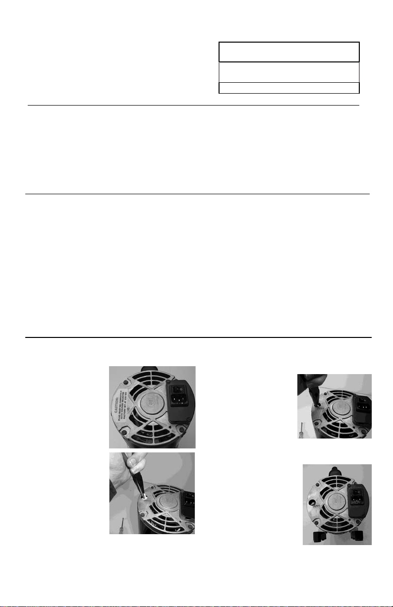
Dual Voltage Motor Power Conversion (if applicable)
STEP 1
Disconnect the motor
from the power supply
and remove. Remove the
yellow “CAUTION”
sticker from the back of
the motor.
STEP 2
Pull up on the white
plastic “arrow” switch
using needle-nosed
pliers until the switch is
loose inside the motor
housing (it will not come
completely out of the
motor).
Note: Do not try to turn
or rotate the switch until it has been pulled up and is
loose.
STEP 3
Point the arrow toward the
desired voltage setting and
push the switch back down
into the motor. The arrow on
the switch should be sub-
flush of the motor housing
when correctly installed at
the desired voltage.
HI = 230 VAC / 50 Hz
LO = 115 VAC / 60 Hz
STEP 4
Replace the yellow
“CAUTION” sticker over the
voltage selector switch.
Ensure that the voltage setting
corresponds with the power
supply that the motor is
plugged into.
*Warranty is void if the set vacuum pump voltage does not match the power supply. Dual voltage motors are factory set to 230V/50Hz.
5
Page 6
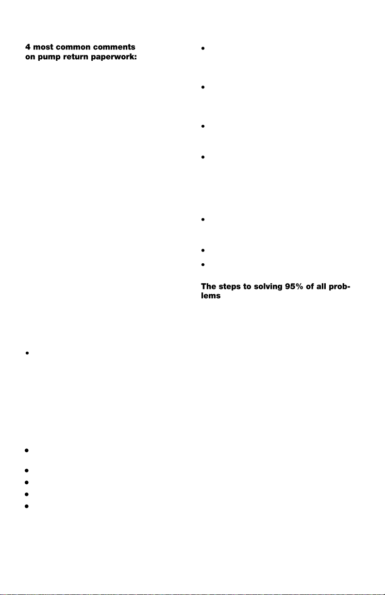
Basic Troubleshooting
1) "Will not pump." This usually means the
pump will not pull a deep enough vacuum.
This can be caused by a bad seal on the gas
ballast valve or contaminated oil.
SUGGESTION: Change gas ballast “O”-ring,
change oil twice and recheck vacuum.
2) "Will not pull below 1000 microns."
SUGGESTION: Check gas ballast “O”-ring. Test
pump to determine actual pull down. Remove all
hoses and connect vacuum sensor directly to
pump.
3) "Noisy." Pumps are noisy when they have
not achieved a high vacuum. In intermediate
vacuum, there will be oil, vane and exhaust
noises.
SUGGESTION: Listen to the pump at high vacuum. If relatively quiet, the pump is running
properly. If still noisy, there may be a system
leak.
4) "Repair and return." This is the most diffi-
cult return comment to handle, since we are
unsure of what needs to be done to keep the
customer satisfied.
SUGGESTION: Be specific about the problem
with your pump if returning it. Please include a
separate sheet of paper documenting your problem.
Starting problems
Be sure pump is plugged into live receptacle
with line voltage plus or minus 10% of voltage on motor nameplate. Long extension
cords can greatly reduce voltage and cause
problems.
Pump/oil temperature must be 30°F (-1°C) or
higher. Open intake to atmosphere and switch
on pump; run up to speed before connecting
to system.
Your SuperEvac pump features a heavy-duty
high torque motor for cold weather starting,
but dirty oil makes starting more difficult,
causing unnecessary wear on your unit.
Dropping your pump can damage it. In a
locked pump condition, motor will not run
and the thermal overload will kick out.
Disconnect power cord and set pump with
front cover face down on table. Reach into
coupling area and try to rotate the coupling.
Do not use pliers. if the pump does not rotate, it is “locked up.”
Oil leakage
If leak develops between front and rear half of
oil case, tighten all seven screws. Replace
gasket if necessary.
If shaft seal leaks, replace it.
Wipe pump dry and watch for source of leak.
Tighten screws and repair.
1) Check oil level when pump is running. It
should be at or above the indicated levels...the
level necessary for proper operation.
2) Check all connections. Make sure they are
tight. Put vacuum pump oil on gas ballast
“O”-ring.
Note:
This unit generates a deep vacuum that can be harmful to human tissue. Do not expose any part
of the human body to the vacuum.
Do not operate this unit with the exhaust blocked or restricted.
Keep unit a minimum of 4” (10 cm) from objects for adequate cooling of motor.
Continuous sound pressure level of this unit can exceed 70dB (A).
Vacuum pump exhaust may contain harmful vapors. Provide adequate ventilation.
6
Page 7
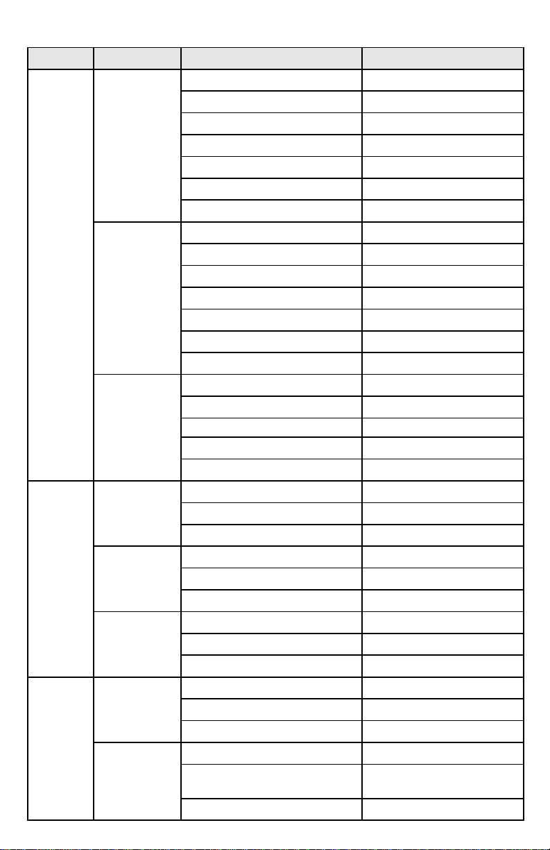
Diagnostics Chart
Condition Pump Area Possible Problem Solution
Poor
vacuum
Oil
Leaks
Pump
won’t
start
Quiet pump
Ultimate
vacuum of
pump - does
not meet
mfg. spec
(read with
thermocouple)
Noisy
pump
Exhaust
Seal
Case
Motor
stalled
hot/cold
Thermal
Dirty oil Flush 1 to 3 times
Coupling or set screw loose Repair or replace
Bad exhaust valve Repair or replace
Pump not oiling Call factory
Vanes not functioning Call factory
Stator misaligned Call factory
Worn pump bearings Call factory
Pump dropped Call factory
Bad thermocouple Clean or replace
Bad motor Repair or replace
Dirty oil Flush 1 to 3 times
Air leaks Repair or replace
System leaks Isolate/repair
Fitting sealant compound Repair or replace
System leaks Repair leaks
Low oil level Add/replace
Dirty oil Flush 1 to 3 times
Worn pump Replace module, call factory
Air leaks at fittings or gasket seals Replace/repair
Oil level high Adjust oil level
System vented pressure through pump Check oil level, add or replace oil
Pump tipped over Check oil level, add or replace oil
Pump shaft Repair
Worn or damaged seal Replace
Motor loose Adjust/tighten, check seal
Gasket bolts loose Tighten
Oil drain fitting Repair or replace
Gasket damaged Replace
Damaged motor Repair or replace
Damaged pump Replace/call factory
Closed gas ballast on pumps Open intake fitting and gas ballast
Low voltage Shorter extension cord
Cold weather cut-out Open intake fitting for 1 minute
Dirty oil Flush 1 to 3 times
to warm up while starting
7
Page 8
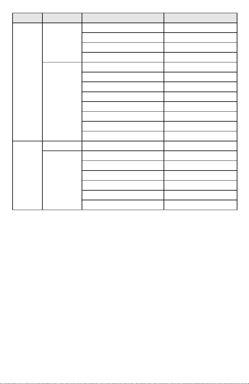
Condition Pump Area Possible Problem Solution
Unusually
noisy
High
temp
Motor
Pump
Low voltage Short extension cord
Motor
Pump
Worn motor Replace motor
Loose motor bolts Tighten bolts
Coupling drive Adjust/replace coupling
No end play on shaft Adjust coupling
Dirt, low, improper oil Flush and replace oil
Air leaks:
1) caps/connection Tighten
2) Gaskets/”O”-rings Replace/put on oil
3) Fittings Replace/reseal
Damaged or worn bearing Call factory
Damaged or worn stators Call factory
Pump out of adjustment Call factory
Dirty oil Flush and replace
Low oil Add/replace
Lint/foreign material Open gas ballast
Parts friction Replace oil/call factory
Too small for system Size pump for system
Air leaks Replace/repair
8
Page 9
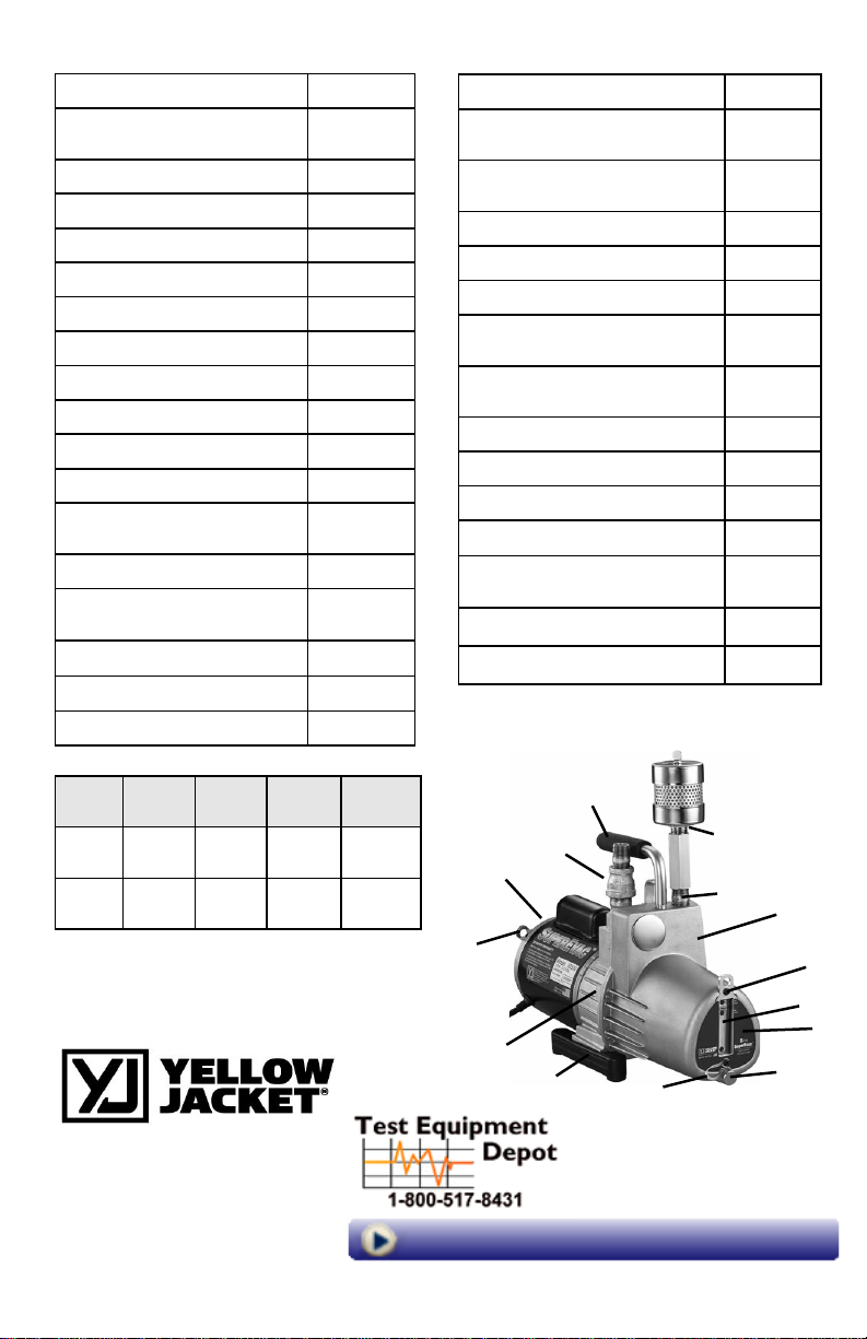
Replacement Parts Models 93530, 93533, 93539 - 8 CFM (190 L/M)
Pump Oil Cover
1. Complete cover (individual
parts listed below)
2. Handle with screw 92941
3. Exhaust filter assembly 93386
4. Oil fill/intake fitting 93359
5. Pair of Sight Glass Screws 92933
6. Sight Glass Bezel 92934
7. Sight Glass and Gasket 92935
8. Tether 92932
9. Cover Label 92946
10. Oil Drain Plug 92956
Vacuum cartridge
11. Complete cartridge with
oil cover gasket
Mounting body
12. Complete body (individual
parts listed below)
13. Ballast Plug 93358
14. Shaft seal 93354
15. “O”-ring for gas ballast 93398
92955
92957
92958
Motor
16. 1/2 hp - 230V/50 Hz*
(includes items 18 and 19)
17. 1/2 hp - 115V/60 Hz*
(includes items 18, 19 and 20)
18. 8/32 x 7-1/4” motor bolts (4) 93099
19. Rocker style switch 93117
20. 8’ long cord 93115
21. 8’ long EU cord (detachable
IEC-320)
22. 8’ long UK cord (detachable
IEC-320)
Final assembly parts
23. 8/32 x 5/8” socket head screws 93506
24. Oil cover gasket 92942
25. Drive coupling 93047
26. Right or left leg assembly with
screws
27. Cartridge Baffle 92940
28. Shoulder Strap Mount 92943
Damaged cords must be replaced by special
assemblies available from the manufacturer or
its distributors.
1/2 hp
93513
1/2 hp
93505
95431
95432
93034
Model Voltage Fre-
quency
93530 60 Hz 115V 30.8 lbs.
93533 50 Hz* 230V* 32.5 lbs.
*The 93533 is factory wired for 230V. It can also
be configured for 115Vac. Remove the motor
switch plate and make connections as shown on
the motor label.
Cur-
rent
7A
4A
Weight
(14.0 kg)
(14.7 kg)
16 or 17,
18, 19, 20,
21, 22
28
12, 13, 14, 15
Visit us at www.TestEquipmentDepot.com
©2019 Ritchie Engineering Co., Inc. Printed in U.S.A.
2
4
3
4
26
99 Washington Street
Melrose, MA 02176
Phone 781-665-1400
Toll Free 1-800-517-8431
8
Part #142884 Rev. D
1
5
6, 7
9
10
9
 Loading...