

Page 1
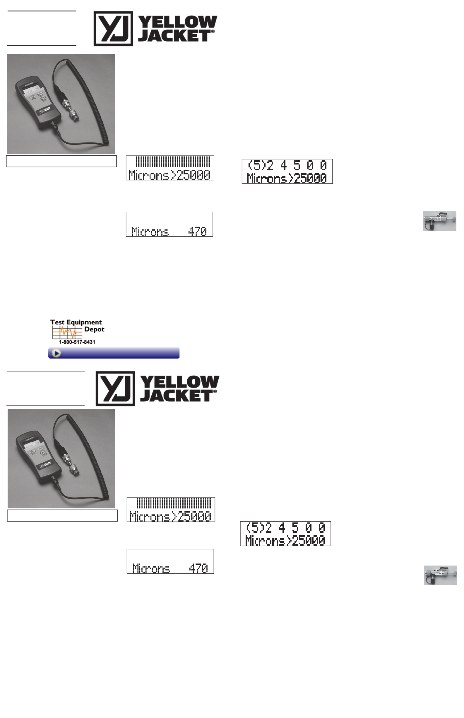
Handheld
Vacuum Gauge
69086
Owner’s Manual
Features
Replaceable sensor
Measures vacuum in 7 different international units
Long battery life
20 minute auto-off
Package Contents
Vacuum Gauge and sensor
Operating instruction manual
Battery
Pouch
Replacement Parts
Sensor (Part #69087)
Cable (Part #69088) - Original version
Cable (Part #40819) - New detachable version
Battery door and screw (Part #69089)
Pouch (Part # 69090)
SPECIFIC
Battery: 9 volt alkaline
Battery Life: Approximately 25 hours continuous use
Low Battery Indicator: The display will flash
Resolution: 2 digits
Display: - Numeric readout from 25000 microns to
10 microns
- Bar graph readout above 25000 microns
ATIONS
“Battery Low!”
OPERATING INSTRUCTIONS
Battery Installation
Remove the battery compartment cover screw and
remove the cover. Observing the polarity marking,
press the battery into the compartment. Replace
battery compartment cover and screw.
Basic Set-up Sequence
1. Connect the gauge to a dry part of the system.
The sensor will not work if it becomes filled with
system oil.
2. Turn on the gauge.
At atmospheric pressure the display will show a series
of bars on the top row and the bottom row of the display will indicate that the pressure is above the maximum numeric readout (e.g. >25000). The bars are
intended to show vacuum progress only. The number
of bars displayed at atmospheric pressure will vary.
As the pressure drops, the bar graph on the top row of
the display will reduce. When the pressure falls into the
readout range, the numeric readout will begin to
change and the bar graph will no longer appear.
3. The gauge will shutoff on its own after
approximately 20 minutes. When the gauge is
turned back on, it will take approximately
seconds
for the sensor to warm-up and the true
reading to appear.
Units Selection
The vacuum gauge reads in 7 different international
units. The readout units can be changed when the
gauge is on by pressing the UNITS button. Each press
of the UNITS key will change the units displayed. If
you go beyond the desired units, continue to press the
UNITS button until the desired units appears again.
The gauge will default to this units selection at the next
power-up.
99 Washington Street
Melrose, MA 02176
Phone 781-665-1400
Toll Free 1-800-517-8431
30
Cleaning the sensor
Troubleshooting
1. Use Isopropyl Alcohol to clean the sensor.
Remove the stem adapter from the sensor body by
2.
loosening the 1/4” pipe fitting. The pipe fitting is sealed
with Teflon thread tape. Remove all Teflon thread tape
from the stem adapter and the sensor body after
disassembling.
3. Add alcohol to sensor, cover with thumb and shake like
a test tube. Pour solution out noting amount of oil in
alcohol. If sensor is very oily you may need to repeat
proces
s.
Clean the stem adapter by rinsing it in alcohol. You can
4.
remove the Schrader core depressor for cleaning but it
must be put back in. Use a needle nose pliers.
5. Apply Teflon thread tape to the male threads of the
stem adapter and re-install it on the sensor body. Do
not use liquid or paste thread sealants.
Changing the Sensor
When connecting a different sensor to the vacuum gauge,
it is important to enter the proper sensor calibration numbers into the vacuum gauge. Follow these steps when
changing sensors:
1. With the gauge turned off, connect the sensor to the
end of the sensor cord. The sensor connector is keyed
with two slots. These must be aligned with the ridges
on the cord connector.
2. Press and hold the SENSOR SETUP button and switch
the gauge on. Hold the SENSOR SETUP button down
until the following display appears:
Flashing “Low Battery!” display: Battery is low - replace
the battery.
No display: Check battery – verify battery polarity and
make sure battery is making good contact with the
spring terminals.
Erroneous vacuum readings: Sensor may be contami-
nated – clean or replace the sensor.
Error codes: Error codes may be generated if the sensor
becomes disconnected or extremely contaminated. Turn
the power off, correct the problem, and try again. If error
codes persist, call the factory for assistance.
TECHNI
CAL INFORMATION
Ti
ps for best evacuation and gauge performance
When pulling a vacuum take the following steps:
The YELLOW JACKET pump features a built-in gauge.
If this reading on this gauge stays in the mid range,
there is either high contamination or a large leak in the
system. (Throughout the process, remember the
refrigerant recovery laws.)
If you think there is excessive moisture, blow out the
AC&R system with dry nitrogen wherever possible. This
reduces the amount of contaminants that must be pulled
into the pump, and increases evacuation speed.
The importance and method for avoiding
contamination of
the sensor.
The most common problem affecting the operation of
electronic vacuum gauges is sensor contamination. Oil and
other contaminants in the sensor area may affect the
sensor’s ability to detect changes in vacuum level. All
electronic vacuum gauges are subject to oil contamination.
Oil contamination is usually avoidable and is not covered
3. The 6 digit number across the top of the display is the
sensor calibration number currently in memory. These
digits need to be changed to match the number on the
new sensor. The 6 digit sensor number can be found
on the label wrapped around the sensor
The paren
theses on the display indicate the digit being
.
edited. Use the UNITS button to change the number in
parentheses. Each press of the UNITS button will
increment the digit by 1. If you go beyond the desired
number, continue to press the UNITS button until the
desired digit appears again. When the digit on the
display matches the digit on the sensor label, press the
SENSOR SETUP button to move to the next digit
position. The parentheses will move to the next digit
position on the display.
4. Repeat step 3 until all 6 digits match the digits on the
sensor label. If any of the digits do not match, turn the
gauge off and repeat the process beginning with step 2
above. When the final digit is completed, press the
SENSOR SETUP button. The normal readout display
will appear. The gauge is now ready for use with the
new sensor.
Contrast Adjustment
The vacuum gauge has an LCD display with adjustable
contrast. If a different display contrast is desired, use a
small flat bladed screwdriver to turn the contrast adjustment screw until the desired contrast is achieved. The
contrast adjustment screw can be accessed through the
small hole on the back of the vacuum gauge.
under warranty. Oil is present in all AC/R systems and can
be drawn out of a system during evacuation. It is best to
remove the access fitting core with a YELLOW JACKET
vacuum charge valve and pull the
system below 28” Hg before connecting
the electronic vacuum gauge to the side
port on the valve. This will allow you to
properly isolate the system from the
pump as well as reducing the
chance of contaminating the sensor
18975 Valve Core Tool
with oil from either the system or the vacuum pump. If your
vacuum gauge sensor has been contaminated with oil, you
will see signs of oil in the rubber seal at the end of the
sensor. The vacuum readings will also be higher than
expected. In some cases of extreme contamination the
display will not go below atmospheric pressure.
The vacuum gauge sensor can usually be cleaned with
isopropyl alcohol. See the section titled “Cleaning the
Sensor”.
To keep your vacuum gauge sensor accurate, it is best to
avoid oil contamination. Here are some recommendations
to avoid contamination:
1.
Inspect fitting for signs of oil before connecting the
vacuum gauge sensor.
2. Keep the sensor vertical when possible.
Connect the gauge directly to the system, away from
3.
the pump.
4. Isolate the pump from the system (and the gauge) with
a valve before turning the pump off. This is very
important when the gauge is mounted near the pump.
Visit us at www.TestEquipmentDepot.com
Calibrador manual
de vacío
69086
Manual del propietario
Características
Sensor intercambiable
Mide el vacío en 7 unidades internacionales
iferentes
d
Pila de larga duración
Autoapagado después de 20 minutos
Contenido
Calibrador de vacío y sensor
Manual de funcionamiento
Pila
Bolsa
Piezas de repuesto
Sensor (N.º de ref. 69087)
Cable (N.º de ref. 69088) - Versión original
Cable (N.º de ref. 40819) - Nueva versión desmontable
Tapa del compartimento de las pilas y tornillo
(N.º de ref. 69089)
Bolsa (N.º de ref. 69090)
ESPECIFIC
Precisión: 9 volt alkaline
Duración de la pila: aproximadamente 25 horas de
uso continuo
Indicador de voltaje bajo de la pila: En la pantalla
aparecerá parpadeando la leyenda: “Battery low!”
Resolution: 2 dígitos
Pantalla: - lectura numérica de 25.000 micras a 10
Printed in U.S.A. P/N 180261_B
micras
- lectura en gráfico de barras superior a las
25.000 micras
ACIONES
INSTRUCCIONES DE FUNCIONAMIENTO
Instalación de la pila
Desatornille la tapa del compartimento de la pila y retire la
tapa. Teniendo en cuenta las marcas de polaridad,
presione la pila dentro del compartimento. Reemplace la
tapa del compartimento de la pila y atornille.
Secuencia básica del sistema
1. Conecte el calibrador a una parte seca del sistema. El
sensor no funcionará si se llena de aceite del sistema.
2. Encienda el calibrador.
Según la presión atmosférica, la pantalla mostrará una
serie de barras en la fila superior y en la fila inferior de la
pantalla que indicarán que la presión está por encima de la
lectura numérica máxima (p. ej. > 25.000). Las barras sólo
indican el progreso del vacío; el número de barras
indicadas varía según la presión atmosférica.
Conforme desciende la presión, el gráfico de barras en la
fila superior de la pantalla se reducirá. Cuando baje la
presión dentro del rango de lectura, la lectura numérica
comenzará a cambiar y ya no aparecerá el gráfico
de barras.
3. El calibrador se apagará solo después de 20 minutos
aproximadamente. Cuando lo vuelva a encender, el
sensor tardará aproximadamente 30 segundos en
calentarse y en aparecer la lectura real.
Selección de unidades
El calibrador de vacío lee en 7 unidades internacionales
diferentes. Se pueden modificar las unidades de lectura
presionando el botón UNIDADES, cuando el calibrador está
encendido. Cada vez que se presione el botón UNIDADES
se modificarán las unidades mostradas en pantalla. Si se
pasa de las unidades que desea seleccionar, continúe
presionando el botón hasta que las unidades que desea
vuelvan a aparecer. El calibrador aplicará la selección de
unidades a partir de la siguiente vez que lo encienda.
Limpieza del sensor
1. Utilice alcohol isopropílico para limpiar el sensor.
2. Retire el adaptador vástago del cuerpo del sensor aflojando
el accesorio de la pipa de 0,6 cm. El accesorio de la pipa
está sellado con cinta de teflón para roscas. Retire toda la
cinta del adaptador vástago y posteriormente retire el
cuerpo del sensor después de desarmarlo.
3. Añada alcohol al sensor, cúbralo con el dedo pulgar y
sacúdalo como si fuese un tubo de ensayo. Vierta la
solución revisando si hay aceite en el alcohol. Si el sensor
está muy aceitoso puede ser necesario que repita
miento.
procedi
4. Limpie el adaptador vástago enjuagándolo con alcohol.
Puede retirar el depresor central Schrader para limpiarlo,
pero después debe ponerlo de nuevo. Utilice pinzas con
punta de aguja. .
5. Aplique cinta de teflón para roscas a las roscas macho del
adaptador vástago y reinstálelo en el cuerpo del sensor. No
utilice selladores de pasta o líquidos para roscas.
Cambio del sensor
Cuando conecte un sensor diferente al calibrador de vacío, es
importante que introduzca los números adecuados del calibrador de sensor en el calibrador de vacío. Siga los siguientes
pasos para cambiar los sensores:
1. Cuando el calibrador esté apagado, conecte el sensor al
extremo de la cuerda del sensor. El conector del sensor
cuenta con dos ranuras que deben estar alineadas con los
bordes en el conector del cable.
2. Pulse y mantenga pulsado el botón SENSOR SETUP
(Configuración del sensor) y encienda el calibrado
M
antenga pulsado el botón SENSOR SETUP hasta que
aparezca la siguiente leyenda en la pantalla:
3. Los 6 dígitos en la parte superior de la pantalla son el
número
actual de calibración del sensor en la memoria.
Estos dígitos deben modificarse para que concuerden con
el número del sensor nuevo. El número del sensor en 6
dígitos se localiza en la etiqueta de la envoltura del sensor.
Los paréntesis en la pantalla indican el dígito que se está
modificando. Utilice el botón UNITS (Unidades) para
cambiar el número entre paréntesis. Cada vez que pulse el
botón UNITS incrementará el dígito de uno en uno. Si se
excede del número deseado, continúe pulsando el botón
hasta que el dígito que desea aparezca de nuevo. Cuando
el dígito en la pantalla concuerde con el dígito en
del sensor, pulse el botón SENSOR SETUP para
etiqueta
continuar en la siguiente posición de dígito. Los paréntesis se
cambiarán a la siguiente posición de dígito en la pantalla.
4. Repita el paso 3 hasta que los 6 dígitos concuerden con los
de la etiqueta del sensor. Si alguno de los dígitos
concuer
da, apague el calibrador y repita el procedimiento
empezando por el paso 2 antes mencionado. Cuando se
haya completado la modificación final de los dígitos, pulse
el botón SENSOR SETUP. Aparecerá la pantalla normal de
lectura. Ahora el calibrador está listo para utilizarse con el
sensor nuevo.
Ajuste de contraste
El calibrador de vacío tiene una pantalla de cristal líquido con
contraste ajustable. Si desea un contraste diferente en la
pantalla, utilice un destornillador pequeño de punta plana para
girar el tornillo de ajuste de contraste hasta que logre el que
desea. Puede acceder al tornillo de ajuste de contraste a
través de un orificio pequeño en la parte posterior del calibrador de vacío.
el
r.
la
no
Resolución de problemas
Pantalla destellante “Battery low!”: el voltaje de la pila está
bajo, reemplácela.
No aparece nada en pantalla: revise la pila, la polaridad de
la pila y asegúrese de que esté haciendo contacto
correctamente con las terminales de resorte.
Lecturas de vacío erróneas: el sensor puede estar
contaminado, limpie o reemplace el sensor.
Códigos de error: se pueden generar códigos de error si se
desconecta el sensor o está extremadamente contaminado.
Apáguelo, corrija el problema e inténtelo de nuevo. Si
continúa el error, comuníquese con la fábrica para
solicitar asistencia.
Sugerencias para una evacuación y un rendimiento
INFORM
óptimos del calibrador
Para realizar vacío siga las instrucciones a continuación:
La bomba YELLOW JACKET cuenta con un calibrador
integrado. Si la lectura de este calibrador permanece en un
rango medio, entonces hay una contaminación muy alta o
una fuga en el sistema. (Tenga en cuenta las leyes de
recuperación de refrigerantes durante el proceso).
Si considera que hay un exceso de humedad, apague el
sistema AC&R con nitrógeno seco siempre que sea posible.
Este procedimiento reduce la cantidad de contaminantes
que la bomba puede absorber e incrementa la velocidad de
evacuación.
La importancia de evitar contaminantes en el sensor y el
método para hacerlo.
El problema más común que afecta la operación de los
calibradores de vacío electrónicos es la contaminación del
sensor. El aceite y otros contaminantes en el área del sensor
pueden afectar su capacidad para detectar los cambios en el
nivel de vacío. Todos los calibradores de vacío electrónicos
están expuestos a la contaminación por aceite
Por lo general, la contaminación por aceite se puede evitar y la
garantía no la cubre. El aceite se encuentra en todos los
sistemas AC/R y puede extraerse de un sistema durante la
evacuación. Lo mejor es retirar el centro del ajuste del
accesorio con una herramienta para el
centro o espina de la válvula YELLOW
JACKET y ejecutar el sistema por debajo
de 28 pulgHg antes de conectar el calibrador electrónico de vacío al puerto lateral de
la válvula. Esto permite que usted
pueda aislar correctamente el sistema
de la bomba, así como también reducir la posibilidad de contaminar el
sensor con aceite proveniente del
sistema o de la bomba de vacío. Si el sensor del calibrador de
vacío se contamina con aceite, observará rastros de aceite en
el sello de goma que está en el extremo del sensor. Además,
las lecturas de vacío serán más altas de lo esperado. En algunos casos de contaminación extrema la pantalla no funcionará en un rango menor al de la presión atmosférica .
El sensor del calibrador de vacío se limpia normalmente con
alcohol isopropílico. Vea la sección “Limpieza del sensor”
Lo mejor es evitar la contaminación para que el sensor del
calibrador de vacío continúe funcionando con precisión. A
continuación se enumeran algunas recomendaciones para
evitar la contaminación :
1.
Revise el accesorio para detectar rastros de aceite antes de
conectar el sensor del calibrador de vací
Mantenga el sensor en posición vertical cuando le sea
2.
posible.
Conecte el calibrador directamente al sistema, lejos de
3.
la bomba.
4.
Aísle la bomba del sistema, y del calibrador, con una válvula
antes de apagar la bomba. Este procedimiento es muy
importante cuando el calibrador está montado cerca de
la bomba.
ACIÓN TÉCNICA
18975 herramienta para
el centro o espina de la
o.
válvula
 Loading...