

Page 1
99 Washington Street
Melrose, MA 02176
Phone 781-665-1400
Toll Free 1-800-517-8431
Visit us at www.TestEquipmentDepot.com
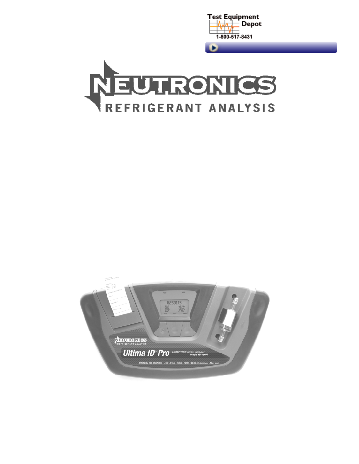
ULTIMA ID PRO™
Model RI-700H HVAC/R REFRIGERANT ANALYZER
OPERATION MANUAL
Manual Part Number: 5-06-7000-70-0
Manual File MN-A-0190 Rev. D
Revised: December 8, 2010
Manual Part Number:
5-06-7000-70-0
Manual File:
MN-A-0190 Rev. D
Revision Date: December 8, 2010 Page 1-3
Page 2

Table of Contents
TABLE OF CONTENTS ................................................................................................................................................ V
FOR YOUR SAFETY: ................................................................................................................................................... VI
ANALYZER WARNINGS ............................................................................................................................................. VI
WELCOME ................................................................................................................................................................ VIII
1 INTRODUCTION AND OVERVIEW .................................................................................................................. 1-9
1.1 GENERAL ....................................................................................................................................................... 1-9
1.2 FEATURES .................................................................................................................................................... 1-10
1.3 ULTIMA ID PRO COMPONENTS ....................................................................................................................... 1-11
Ultima ID Pro Base Unit ......................................................................................................................... 1-11
Low Side Vapor Sample Hose ................................................................................................................ 1-11
AC Power Adapter ................................................................................................................................. 1-12
Control Panel ......................................................................................................................................... 1-13
Back Panel Connections ........................................................................................................................ 1-13
Hard Shell Storage/Carrying Case ........................................................................................................ 1-14
2 ULTIMA ID PRO OPERATION ......................................................................................................................... 2-1
2.1 FIRST USE ...................................................................................................................................................... 2-1
Battery Installation (Optional) ................................................................................................................ 2-1
2.2 TURNING ON THE UNIT .................................................................................................................................... 2-2
2.3 CALIBRATION .................................................................................................................................................. 2-2
2.4 VAPOR SAMPLING ........................................................................................................................................... 2-3
2.5 LIQUID SAMPLING ........................................................................................................................................... 2-3
2.6 VIEWING THE TEST RESULTS ........................................................................................................................... 2-4
2.7 CONTAMINATED BLEND REFRIGERANTS ........................................................................................................... 2-4
2.8 PURE BLEND REFRIGERANTS .......................................................................................................................... 2-4
2.9 BLENDS WITH INCORRECT COMPONENT RATIOS ................................................................................................ 2-5
2.10 PRINTING THE TEST RESULTS .......................................................................................................................... 2-5
3 MAINTENANCE & TROUBLESHOOTING ....................................................................................................... 3-6
3.1 SETTING THE LCD CONTRAST .......................................................................................................................... 3-6
3.2 CHANGING THE WHITE PLASTIC SAMPLE FILTER .............................................................................................. 3-6
3.3 REPLACING THE SAMPLE HOSE ....................................................................................................................... 3-7
3.4 CHANGING THE PRINTER PAPER ...................................................................................................................... 3-7
3.5 SOFTWARE UPDATES ...................................................................................................................................... 3-8
3.6 ERROR MESSAGES .......................................................................................................................................... 3-8
APPENDICES .......................................................................................................................................................... 3-9
3.7 SPARE PARTS LIST ......................................................................................................................................... 3-9
3.8 APPENDIX B - SPECIFICATIONS ........................................................................................................................ 3-9
3.9 APPENDIX E – WARRANTY ......................................................................................................................... 3-10
Manual Part Number:
5-06-7000-70-0
Manual File:
MN-A-0190 Rev. D
Revision Date: December 8, 2010 Page v
Page 3

For Your Safety:
PLEASE READ THIS MANUAL IN ITS ENTIRETY BEFORE ATTEMPTING
INSTALLATION OR OPERATION! Attempting to operate the Ultima ID Pro without
fully understanding its features and functions may result in unsafe conditions
• Always use protective eye wear and observe proper safety procedures when working with
pressurized gases.
Read and understand the entire manual BEFORE attempting to operate the instrument.
Analyzer Warnings
• Refrigerant Blend Warning: The HVAC industry is ever evolving new refrigerants. Many of
these new blends can be identified and/or profiled using the Ultima ID Pro. A list of tested
refrigerants and their characteristics is provided in the appendix of this manual.
• Sample Filter Warning: Replace the sample filter of the instrument AS SOON AS RED SPOTS
OR DISCOLORATION BEGIN TO APPEAR ON THE OUTSIDE DIAMETER OF THE WHITE
ELEMENT. Failure to properly maintain and replace the sample filter will result in severe
damage.
• Sample Input Warning: The instrument includes two hose assemblies. One for High Side Liquid
sampling and one for Low Side Vapor Sampling. Failure to use the correct hose on the proper
sample port may result in incorrect readings and/or damage to the instrument. DO NOT
attempt to introduce liquid or samples heavily laden with oil into the Low Side sampling hose.
• Damage caused to the instrument due to the use of the wrong hose on the wrong port will void
the warranty!
• Battery Charger Warning: When charging the optional battery with the 1000mA charger, the
charger will become warm. If the charger becomes hot, unplug the charger immediately!
When charging multiple battery packs, allow the charger to cool between each battery.
Manual Part Number:
5-06-7000-70-0
Manual File:
MN-A-0190 Rev. D
Revision Date: December 8, 2010 Page vi
Page 4

General Cautions
• Always inspect the sample hose before each use. Re
obstructed
or fouled with oil.
place the hose if it appears cracked, frayed,
• ALWAYS turn the compressor off before connecting the instrument to an air conditioning
stem
sy
.
• Always wear eye and skin protection when working with refrigerants. Escaping refrigerant
vapors will present a freezing danger.
• To reduce the risk of electrical shock, do not disassemble the instrument; do not use the
instrument in wet or damp areas.
• DO NOT direct refrigerant vapors venting from hoses towards the skin.
• DO NOT disassemble the instrument. There are no serviceable components internal to the
instrument and disassembly will void the warranty.
• ALWAYS place the Analyzer on a flat and sturdy surface.
• DO NOT utilize any other hose other than those supplied with the instrument. The use of other
hose types will introduce errors into the refrigerant analysis and instrument calibration.
• ALWAYS verify that the refrigerant to be tested
emit heavy l
• NEVER admi
oads of oil or liquid.
t any sample into the instrument at pressures in excess
from the Low
Side does not contain or
of 500 psig.
will not
• NEVER obstruct the air intake, sample exhaust or case vent ports of the instrument during use.
Manual Part Number:
5-06-7000-70-0
Manual File:
MN-A-0190 Rev. D
Revision Date: December 8, 2010 Page vii
Page 5

WELCOME
Thank you for purchasing the ULTIMA ID PRO Refrigerant Analyzer.
The Ultima ID Pro is the most advanced refrigerant analyzer ever designed for determining the purity of
common gaseous refrigerants. It has many features to offer the user, which will be described in this manual.
We recommend that all personnel who use this instrument read this manual to become more familiar with
its proper operation.
Copyright ©2010 Neutronics Inc.
This work is protected under Title 17 of the US Code and is the sole property of Neutronics Inc. No part of this document may
be copied or otherwise reproduced, or stored in any electronic information retrieval system, except as specifically permitted
under US copyright law, without the prior written consent of Neutronics Inc.
Manual Part Number:
5-06-7000-70-0
Test Equipment Depot - 800.517.8431 - 99 Washington Street Melrose, MA 02176 - TestEquipmentDepot.com
Manual File:
MN-A-0190 Rev. D
Revision Date: December 8, 2010 Page viii
Page 6

1INTRODUCTION AND OVERVIEW
1.1 General
Contamination and mislabelling of refrigerants either in storage cylinders or air conditioning systems can
lead to component corrosion, elevated head pressures and system failures when utilized by unsuspecting
technicians. The ability of the technician to determine refrigerant type and purity is severely hampered
by the presence of air when attempting to utilize temperature-pressure relations. The development of
various substitute refrigerants further complicates the ability of a technician to identify refrigerant purity
based upon temperature-pressure relationships. The substitute refrigerant blends can also introduce a
flammability hazard to the technician and the ultimate end user of the air conditioning system.
The Neutronics Ultima ID Pro Refrigerant Analyzer provides a fast, easy and accurate means to determine
refrigerant purity in refrigerant storage cylinders or directly in air conditioning systems. The instrument
utilizes non-dispersive infrared (NDIR) technology to determine the weight concentrations multiple of
refrigerant types. Refrigerant purity is displayed on the LCD Screen. The user must determine acceptable
levels of purity based on their recovery or use standards.
The instrument is supplied complete with a ¼” Flare Vapor sampling hose, a ¼” Flare Liquid sampling
assembly, a 100/240 VAC power transformer, built in printer, and all required plumbing housed within a
rugged, portable, storage case.
Sample gas is admitted into the instrument through one of the two supplied sampling hoses and
presented to the sensing device. The instrument provides the user with direct percent by weight
concentrations. Note that the instrument does not consider air to be a contaminant.
The instrument interfaces with the user with an LCD graphic display, status indicator lamps, push button
communication switches and an alarm horn. Alarm indications are provided to alert of instrument fault
conditions. Direct percent by weight concentrations of the sample refrigerant is provided on the display
as well as user directions and prompts. An on-board printer is provided to print an on-the-spot analysis
report.
The Neutronics Ultima ID Pro Refrigerant Analyzer provides the refrigerant technician with excellent
knowledge of refrigerant type and purity as well as protection against refrigerant contamination and
potential flammability.
Manual Part Number:
5-06-7000-70-0
Manual File:
MN-A-0190 Rev. D
Revision Date: December 8, 2010 Page 1-9
Page 7

1.2 Features
The Ultima ID Pro Refrigerant Analyzer is the most advanced portable instrument ever manufactured for
determining the purity of gaseous refrigerants for the HVAC-R market.
Features Include:
• Advanced ergonomic design
• Rugge
d rubberized hand gr
• Large graphic display with on-screen instructions
• Fast 60 second test time
• Built in printer for instant analysis report
• Vapor or Liquid Sampling ability
• Internal, rechargeable battery (optional) for cordless operation in any location
• Hard shell carry/storage case
• Remote Software Update port
ips
Manual Part Number:
5-06-7000-70-0
Manual File:
MN-A-0190 Rev. D
Revision Date: December 8, 2010 Page 1-10
Page 8
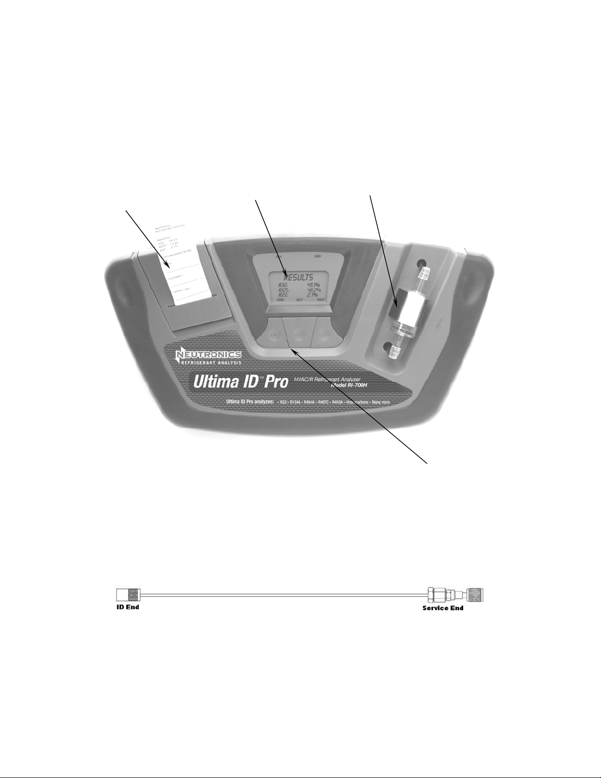
1.3 Ultima ID Pro Components
Ultima ID Pro Base Unit
The Ultima ID Pro base unit houses the Graphic Display, Infrared Bench, Electrical Connections, and
Optional Printer Module. These components require no maintenance, therefore there are no serviceable
components internal to the instrument, and disassembly will void the warranty.
Printer
Control Panel
Sample Filter
User Interface
Low Side Vapor Sample Hose
The 6-foot (1.8 meter) Low Side Vapor Sample Hose is constructed of a polyurethane tube. A Brass flow
restrictor acts to reduce pressure at the sample connection point and reduce the introduction of harmful
oil into the machine. The maximum inlet pressure is 500 psig. The hose is provided with an instrument
inlet port mating connector on one end and a ¼” SAE female flare coupling nut on the service end.
Manual Part Number:
5-06-7000-70-0
Manual File:
MN-A-0190 Rev. D
Revision Date: December 8, 2010 Page 1-11
Page 9
(
)
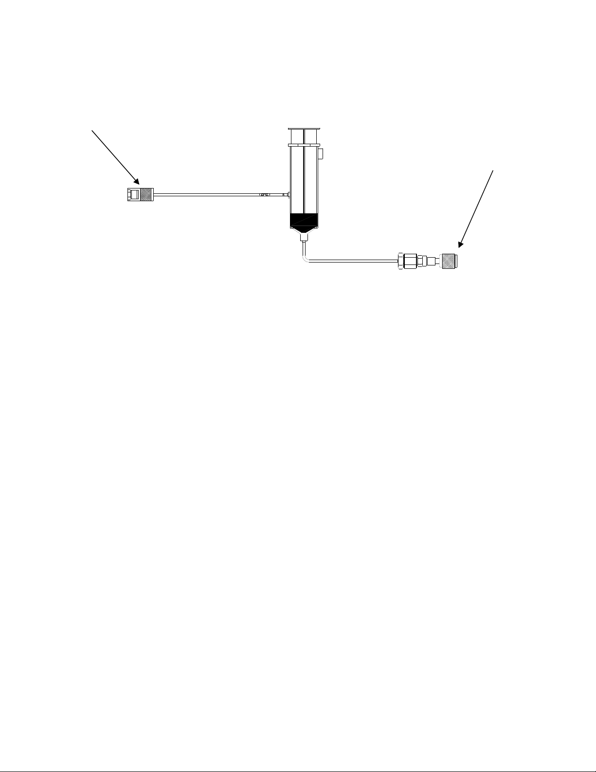
Analyzer End
High Side Liq
uid Sample Hose
Service End
1/4 SAE Flare Nut
The 6-foot (1.8 mete
r) High Side Sample Hose is constructed of a polyurethane tube with an oil reservoir.
A Brass flow restrictor acts to transform Liquid refrigerant to Vapor at the sample connection point while
the Oil Trap Syringe collects oil and provides a means of expulsion after the test is complete. The
maximum pressure is 500 psig. The hose is provided with magnet for attaching it to the tank and an
instrument inlet port mating connector on one end and a ¼” SAE female flare coupling nut on the service
end.
AC Power Adapter
The Ultima ID Pro is powered via a 100/240 VAC 50/60 Hz power transformer. This transformer is
included with each unit and converts a standard 100/240 VAC 50/60 Hz wall outlet to 12VDC to power
the device. An optional internal and rechargeable battery kit is available separately. Note: Use of any
other power source may cause damage to the unit and void the warranty.
Manual Part Number:
5-06-7000-70-0
Manual File:
MN-A-0190 Rev. D
Revision Date: December 8, 2010 Page 1-12
Page 10
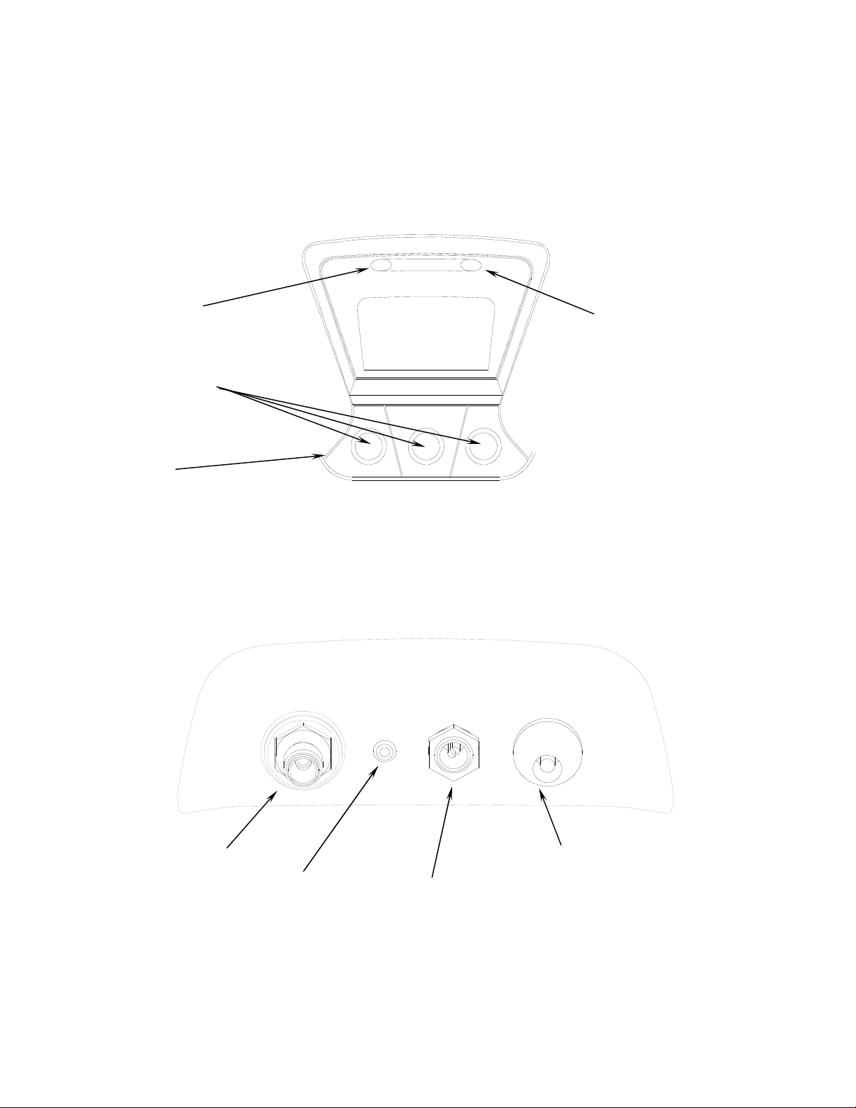
Control Panel
The Control Panel serves as the main user interface. The Control Panel features three soft key buttons
that change their function as the instrument changes modes. The current function for each button is
displayed by the soft key label at the bottom of the graphic display. Red and Green LED’s at the top of the
Control Panel are used for visual status indications.
Green LED
Graphic
Display
Soft Key
Buttons
Power
On/Off
Red LED
Back Panel Connections
The connections located on the back panel are illustrated below.
CAUTION: The sample outlet port should never be obstructed. Keep the sample outlet port free and
clear at all times. Do not operate near open flame.
Sample Inlet
Manual Part Number:
5-06-7000-70-0
Sample Outlet
Battery Charge Port
Manual File:
MN-A-0190 Rev. D
12VDC Power Input
(AC Adapter)
Revision Date: December 8, 2010 Page 1-13
Page 11
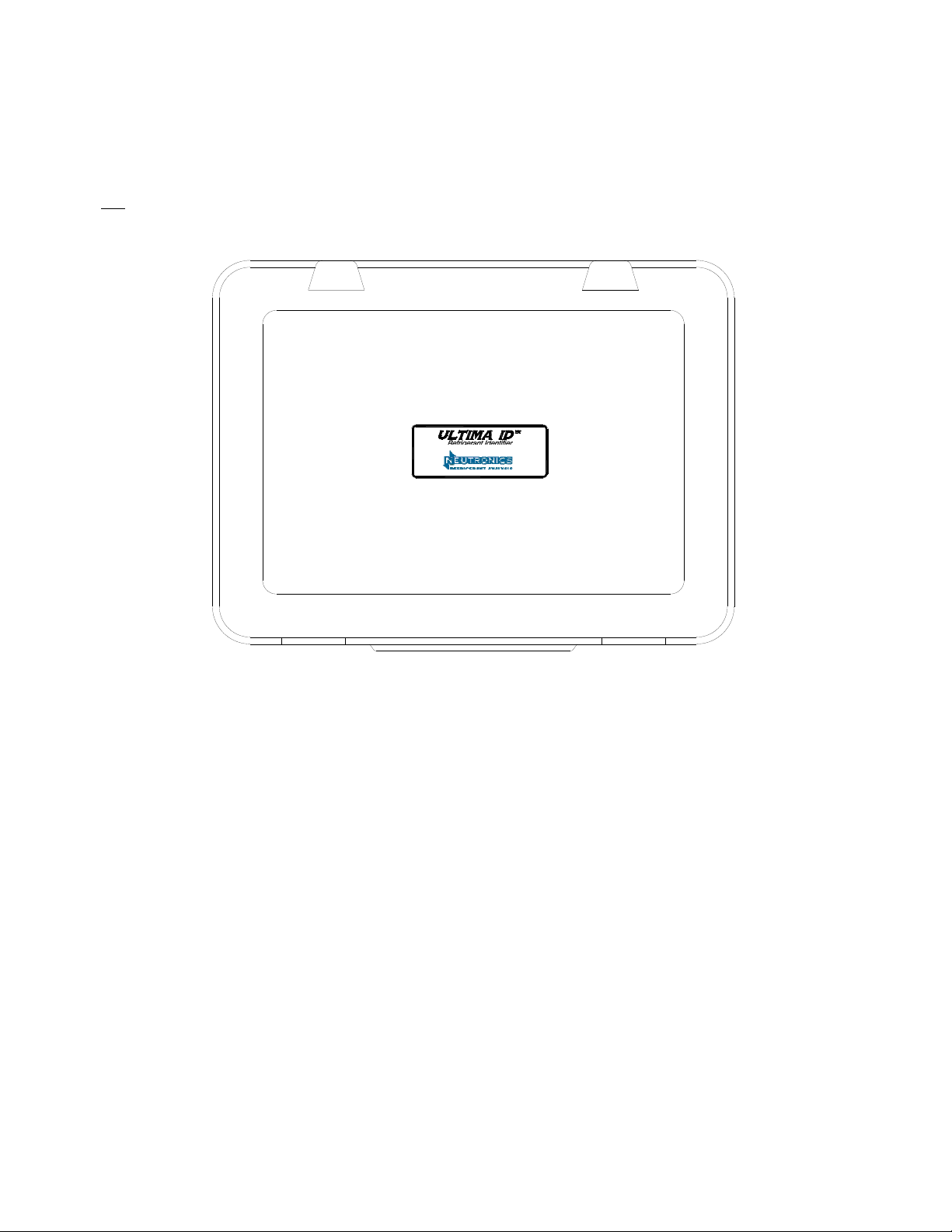
Hard Shell Storage/Carrying Case
The hard shell storage/carrying case is custom fit to the Ultima ID Pro. It provides rugged protection for
the instrument as well as convenient storage for all components. The enclosure is general purpose and is
not
watertight.
Manual Part Number:
5-06-7000-70-0
Test Equipment Depot - 800.517.8431 - 99 Washington Street Melrose, MA 02176 - TestEquipmentDepot.com
Manual File:
MN-A-0190 Rev. D
Revision Date: December 8, 2010 Page 1-14
Page 12
2ULTIMA ID PRO OPERATION
2.1 First Use
Battery Installation (Optional)
The Ultima ID Pro has, as an option, an internal rechargeable battery. If your Ultima ID Pro is
equipped with the optional rechargeable battery, you must first install and charge the battery prior
to use. NOTE: The Ultima ID Pro can be operated with or without the battery using the supplied
AC adapter. Refer to Section 2.2 for instructions.
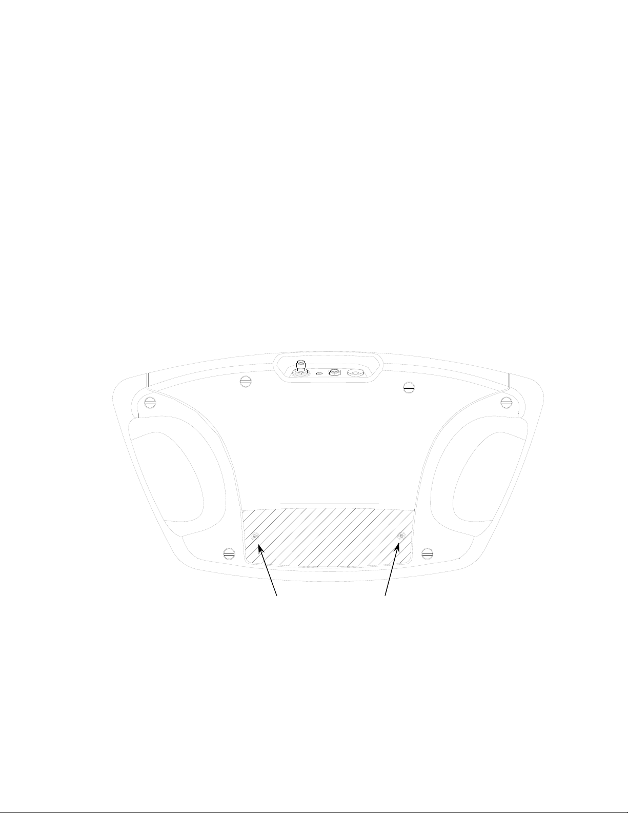
To install the optional battery, remove the battery cover from the back of the unit by unscrewing
the two screws as shown below.
SAE J1771 CERTIFICATION
Refrigerant Diagnostic Tool Design
Certified by Intertek Testing Services (ITS)
to Meet SAE J1771 to identify
CFC-12 (R-12) or HFC-134a (R-134a)
to 98% purity. Also this equipment will
detect 2% or greater of air in HFC-R134a
(R-134a).
For Accuracy, see Manual.
LISTED 6P03
Miscellaneous Refrigerant Equipment
R
12 VDC, 1A; Design Pressure: 300 psig
Refrigerant Type: R-12, R-134a
Design Pressure: 300 psig
NEUTRONICS INC. MODEL No: UID
456 Creamery Way, Exton, PA, 19431 USA
(610) 524-8800, www.NeutronicsInc.com
WARNING-TO REDUCE THE RISK OF FIRE:
DO NOT USE THIS EQUIPMENT IN THE VICINITY OF SPILLED
OR OPENED CONTAINERS OF GASOLINE.
Use this equipment in locations with mechanical ventilation that
provides at leat four air changes per hour or locate the equipment
at least 18 inches above to floor.
:
E
D
O
C
E
T
A
D
Battery Cover Screws
Inside of the Ultima I
D Pro battery compartment, locate the male plug on the left side. Slide the
nylon strap around the battery. Insert the battery module into the compartment aligning the
female connector of the battery module with the male plug in the battery compartment. Replace
the cover and snug the screws.
Note: Charge the battery for a minimum of 4 hours with the supplied charger prior to first
use. The Battery cannot be charged with the standard power adapter.
Manual Part Number:
5-06-7000-70-0
Manual File:
MN-A-0190 Rev. D
Revision Date: December 8, 2010 Page 2-1
Page 13

To remove the battery, simply tug gently on the nylon strap, being sure to pull straight up, until
the battery is dislodged. The battery may be charged either inside of the unit or independent of the
unit.
2.2 Turning On the Unit
Connect the included AC power supply to the 12VDC power input jack on the back of the unit.
Plug in the AC power supply to a 100 – 240 VAC outlet. (Note: If the optional battery module is
installed and charged, the AC power supply is not required.) Press the left, soft key, power button
and the splash screen shown in (Figure 1) will appear for approximately three seconds followed
immediately by the screen in (Figure 1A) and then by the warm up screen for 3.5 minutes (Figure
2). After the warm up, the calibration screen may be shown if it is required (Figures 3 and 4).
TO CHANGE
ULTIMA ID PRO
SOFTWARE VERSION
XXX XX.XXX
SETTINGS OR
REPLACE PAPER
ROLL PRESS SET
FOR OTHER HELP
PRESS HELP
SET HELP DONE
WARMING UP
PLEASE WAIT
Figure 1 Figure 2
AIR CALIBRATION IS
NEEDED SOON
1 – POWER DOWN
UNIT FOR 4 HOURS
2 – MOVE UNIT TO
REFRIGERANT FREE
AREA
REFRIGERANT-FREE
AREA
3 – POWER UP AND
SELECT AIR CAL
WHEN PROMPTED
CAL BACK SKIP
Figure 1A
Figure 4 Figure 5 Figure 3
CALIBRATING
THIS WILL ON
TAKE 50 SECONDS
LY
2.3 Calibration
Air calibrations are only required periodically. A reminder to perform air calibrate will appear
after the unit has been powered up 30 times after the last air calibration. The air calibration
can be delayed (skipped) until it is convenient to allow the unit to cool down for at least 4
hours and be placed in a refrigerant-free environment. (Figures 3 and 4). When calibrating, the
unit willbring fresh air into the unit via an internal pump. This fresh air purges any excess
refrigerant and ensures accurate test results. Calibration requires that the hose be disconnected
from the refrigerant cylinder or air conditioning system. (Figure 5).
Manual Part Number:
5-06-7000-70-0
Manual File:
MN-A-0190 Rev. D
Revision Date: December 8, 2010 Page 2-2
Page 14

When the unit is ready for gas testing, the unit will display the screen shown in (Figure 6).
Connect the hose to the tank and press test. The Ultima ID Pro will display the screen shown in
(Figure 7). If you wish to change any of the factory default settings, refer to section 3.
TESTING
READY
1 - CO
NNECT HOSE
2 - OPEN VALVE
3 - PRESS TEST
HELP TEST
THIS WILL ONLY
TAKE 60 SECONDS
ANALYZING THE
REFRIGERANT
Figure 6
Figure 7
2.4 Vapor Sampling
Vapor sampling is the most common process used for identifying refrigerants using the Ultima ID
Pro. It is a simple process requiring the operator to take these 4 steps:
1) Connect the vapor sampling hose to instrument and then to the Low Side Vapor port
the system or cylinder.
2) Open the low side valve of the cylinder and press test.
3) Disconnect the hose from
4) Disconnect the hose from the Ultima ID Pro for storag
the cylinder.
e.
2.5 Liquid Sampling
Liquid sampling is an option that is exclusive to the Ultima ID Pro. It permits the user to flash
liquid into vapour for introduction into the analyzer. To use the liquid sampling assembly, follow
these seven steps:
1) Inspect the liquid sampling asse
syringe is completely
depressed.
2) Connect the appropriate end of the hose to the instrument and the opposite en
liquid sampling assembly to the High Side Liquid port of the system or cylinder. Affix
the oil trap syringe vertically to the tank with the magnet.
3) Open the high side valve of the cylinder. The li
flashed to vapour by the hose assembly. As the liquid is flashed, the plunger on the oil
trap syringe will begin to rise and the flashed refrigerant sample will travel into the
analy
zer.
Wait for
4)
the plunger on the oil trap syringe to expand past the outlet po
5) Press test on the Analyzer.
6) Upon completion of the test, close the valve on the cylinder, disconnect the hose from
the inlet of the oil trap syringe, depress the plunger on the oil trap syringe to expel the
trapped oil.
7) Inspect the hose for signs of oil and replace the hose restrictor if necessary.
8) Disconnect the hose from the Ultima ID Pro
mbly and ensure that the plunger on the oil trap
d of the
quid sample will exit the tank and be
rt.
of
Manual Part Number:
5-06-7000-70-0
Manual File:
MN-A-0190 Rev. D
Revision Date: December 8, 2010 Page 2-3
Page 15

2.6 Viewing the Test Results
Upon completion of the test, the Ultima ID Pro will display a screen similar to that shown in (Figure
8). Pressing the “More” button will display the screen shown in (Figure 9).
RESULTS
R22 97.0%
R410A 3.0%
RESULTS
R22
CONTAMINATED
BACK PRINT MORE
Figure 8
BACK PRINT DONE
Figure 9
2.7 Contaminated Blend Refrigerants
The Ultima ID Pro includes the ability to detect and analyze the composition of many common
R400 Series refrigerants in addition to R134a, R22 and Hydrocarbons. In the event that the
Ultima ID Pro determines that the primary refrigerant in the system or cylinder is one of the
measured refrigerants, the results will display as follows in (Figure 10). Pressing the “MORE”
button will display the detail screen shown in (Figure 11). If the blend or refrigerant mixture is not
recognized, the screen shown in (Figure 12) will be displayed.
RESULTS
RESULTS
R410A 98.7%
R22 1.3%
RESULTS
UNKNOWN
REFRIGERANT
R410A
CONTAMINATED
BACK MORE
Figure 10 Figure 11 Figure 12
BACK PRINT DONE
BACK PRINT DONE
2.8 Pure Blend Refrigerants
The Ultima ID Pro has the ability to Identify the following refrigerants: R408A, R409A, R417A,
R421A, R421B, R422A, R422B, R422C and R427A. In addition, the instrument can both,
Identify and Analyze
Analysis of analyzed pure blend refrigerants will yield additional data regarding the composition of
the refrigerant sample. The Ultima ID Pro will display the blend refrigerant type as shown in
(Figure 13). Pressing the “MORE” button will display the detail screen shown in (Figure 14).
Manual Part Number:
5-06-7000-70-0
the component content of pure R134a, R22, R404A, R407C and R410A.
Manual File:
MN-A-0190 Rev. D
Revision Date: December 8, 2010 Page 2-4
Page 16

RESULTS
100%
R410A
RESULTS
R410A 100.0%
R125 50.0%
R32 50.0%
BACK MORE
BACK PRINT DONE
Figure 13 Figure 14
2.9 Blends with Incorrect Component Ratios
The Ultima ID Pro has the ability to detect blend ratios that have been altered by contamination.
As stated above, the blends that can be identified and analyzed are R404A, R407C and R410A. If
one of these refrigerant blends have incorrect component ratios, it will be displayed as shown
below: (Figure 15). To see the component concentrations press “MORE.” (Figure 16).
RESULTS
COMPONENTS OF
R125 60.0%
R32 40.0%
RESULTS
R410A
BACK MORE
Figure 15 Figure 16
BACK PRINT DONE
2.10 Printing the Test Results
The test results can be printed by selecting the “PRINT” button. After the print is complete,
carefully tear off the printout and the unit will return to the previous screen. Additional printouts
may be made following the same procedure. To exit the test, press the “EXIT” button. (Figures 17,
18, & 19,) show sample printouts for various test results.
(NOTE) Care must be taken when tearing off the printed results to leave a clean edge.
Neutronics Inc.
Refrigerant
Analyzer
UNKNOWN
REFRIGERANT
(Date)
(Technician)
Manual Part Number:
5-06-7000-70-0
Neutronics Inc.
Refrigerant
Analyzer
R22 = 100.0%
(Date)
(Technician)
Figure 17
Manual File:
MN-A-0190 Rev. D
Neutronics Inc.
Refrigerant
Analyzer
R410A = 100.00%
R125 = 49.8%
R32 = 50.2%
(Date)
(Technician)
Figure18 Figure 19
Revision Date: December 8, 2010 Page 2-5
Test Equipment Depot - 800.517.8431 - 99 Washington Street Melrose, MA 02176 - TestEquipmentDepot.com
Page 17

3MAINTENANCE & TROUBLESHOOTING
3.1 Setting the LCD Contrast
The Ultima ID Pro features an adjustable LCD contrast for use in varying light conditions. To
adjust the contrast, press the “HELP” button on the “Ready to Air Cal” screen as shown in Section
2.2, (Figure 1A). The screen will display several options as shown in (Figure 20). Pressing the
“SET” button will display the options in (Figure 21).
TO CHANGE
SETTINGS OR
REPLACE PAPER
ROLL PRESS SET
FOR OTHER HELP
PRESS HELP
SET HELP DONE
Figure 20
TO FEED IN A
NEW PAPER ROLL
PRESS FEED
PRESS SET TO
ADJ LCD CONTRAST
SET FEED DONE
Figure 21
3.2 Changing the White Plastic Sample Filter
When inspecting the sample filter, look completely around the entire outside diameter of the white
filter element located inside of the clear plastic housing. Look for red spots or the beginnings of
discoloration on the white outside diameter of the element. Do not look into the round ends of the
white element for red spots or discoloration. The round ends of the filter may always appear red. If
red spots or discolorations are discovered on the outside diameter, the sample filter requires
replacement to prevent the influx of particulate and oil mists into the instrument.
Obtain a replacement filter, part number 6-02-6000-08-0. Remove the existing filter from the
retaining clip of the instrument by pulling straight up and out. CAREFULLY remove the flexible,
black rubber tubing connections from both ends of the existing filter. DO NOT allow the tubes to
slip back into the internal portion of the case. Discard the existing filter in an environmentally
friendly manner.
Install the tube ends onto the barbs of the replacement filter, taking note to align the flow arrow of
the filter with the flow arrow of the instrument top panel. CAREFULLY slide the tubing back into
the internal portion of the instrument and seat the new filter into the retaining clip. Inspect the
sample hoses for signs of oil entrapment. Replacement of the sample filter usually requires
cleaning or replacement of the sample hoses.
Manual Part Number:
5-06-7000-70-0
Manual File:
MN-A-0190 Rev. D
Revision Date: December 8, 2010 Page 3-6
Page 18
3.3 Replacing the Sample Hose
Inspect the inside diameter of the tube for signs of oil build up, dirt, obstructions, kinks, cuts,
fraying, or any other signs of wear. Oil contamination cannot be cleaned out of sample hoses due
to the density of the oil restrictor. If oil is visible in the Low Pressure Vapor hose, replace the hose
and restrictor with P/N 6-01-6001-23-1.
For the High Side Liquid Sampling Hose, inspect the inside diameter of the tube for signs of oil build
up, dirt, obstructions, kinks, cuts, fraying, or any other signs of wear. Oil contamination cannot be
cleaned out of sample hoses due to the density of the oil restrictor. If oil is visible in the High
Pressure Liquid Trap Hose, replace the hose and restrictor with P/N 6-02-6001-23-1.
To replace the Restrictor Assembly, follow the instructions below:
1) Disconnect the sample hose from the Identifier
2) Remove the brass filter (with hose attached) from the coupler and discard. Be sure to use a
backing wrench so as not to damage the coupler.
3) Check for signs of oil and debris in the coupler.
4)
Using “CRC Brakleen” or similar cleaner which ONLY contains, Tetrachloroethylene and
carbon dioxide, follow safety instructions on the can and spray all parts of the coupler with
the cleaner to remove the oil. DO NOT soak the parts for more than 60 seconds.
5) Allow coupler parts to dry. Check coupler parts for oil once again. Failure to clean the oil
out of the coupler will result in premature clogging of the new filter.
6) Install the new filter, part number 6-01-6001-23-1, into the coupler and lightly tighten,
usually finger tight is sufficient.
3.4 Changing the Printer Paper
Ultima ID Pro Refrigerant Analyzers that are equipped with on-board printers use an inexpensive
thermal paper for printing. The paper roll should be changed when a red stripe appears on the left
side of the printout.
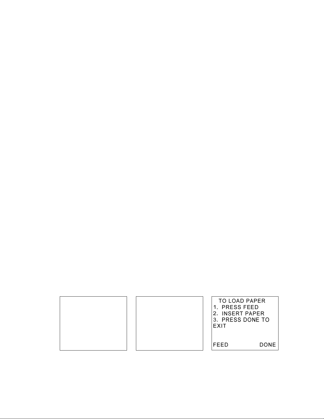
To change the paper roll, press the “HELP” button on the “Ready to Air Cal” screen as shown in
Section 2.2, (Figure 1A). The screen will display several options as shown in (Figure 22). Press
the “SET” button to advance to the screen shown in (Figure 23) and then press the “FEED” button.
TO CHANGE
SETTINGS OR
REPLACE PAPER
ROLL PRESS SET
FOR OTHER HELP
PRESS HELP
SET HELP DONE
TO FEED IN A
NEW PAPER ROLL
PRESS FEED
PRESS SET TO
ADJ LCD CONTRAST
SET FEED DONE
Figure 22 Figure 23 Figure 24
Manual Part Number:
5-06-7000-70-0
Manual File:
MN-A-0190 Rev. D
Revision Date: December 8, 2010 Page 3-7
Page 19
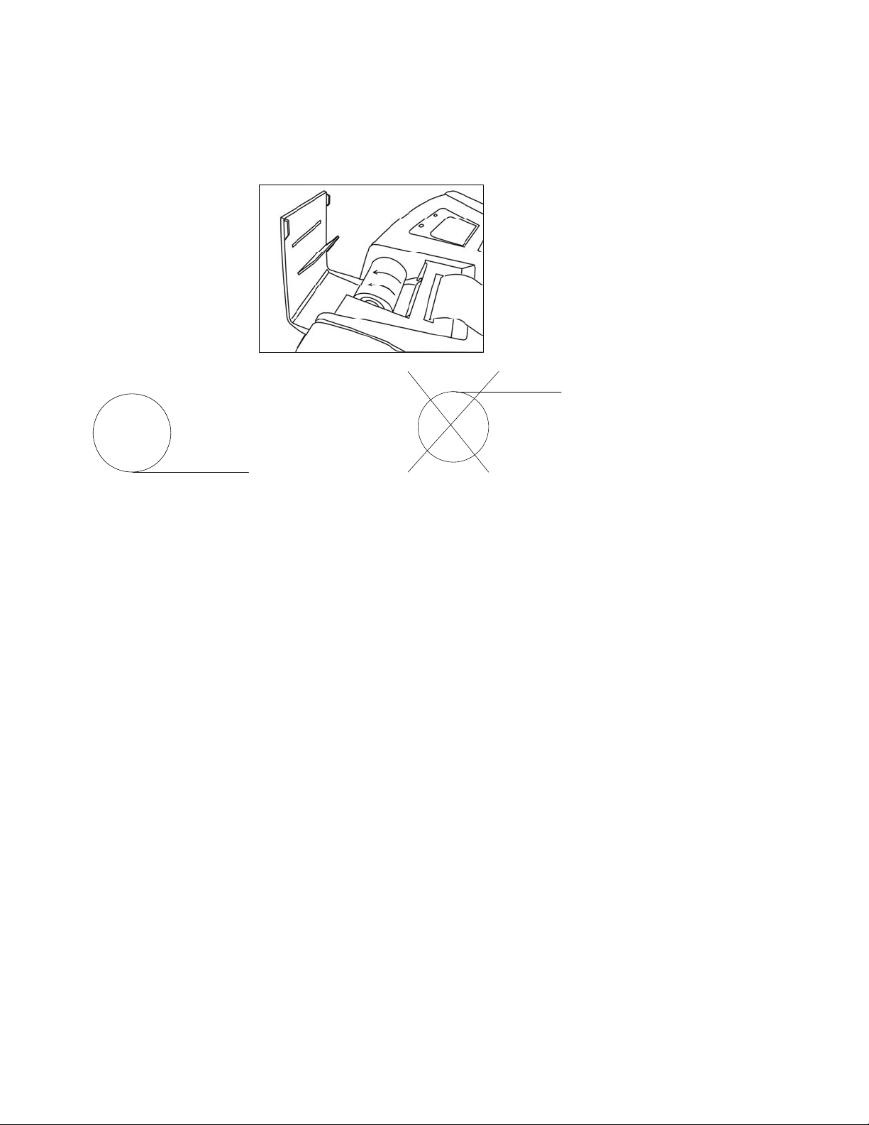
Open the printer door and remove the old roll by tearing the paper as it enters the printer then
pressing the “FEED” button shown in (Figure 24) until the old roll exits the printer completely.
Insert the new paper roll from the underside as shown below:
Press the “F
EED” button shown in (Figure 24) to automatically advance the paper through the
printer. Allow at least 3 in (7cm) of paper to exit the top of the printer. Press the “DONE” to stop
the printer from advancing the paper and exit. Slide the paper through the slot in the printer door
and close the door.
3.5 Software Updates
From time to time, software updates may be made available to improve operating performance or
add additional features. Some updates will be provided at no charge to implement operating
efficiencies while others will be optional, paid upgrades, to add new refrigerants etc. Many of the
updates can be completed by the user however some will require the instrument to be returned to
the factory for new gas calibrations.
The Ultima ID Pro has a USB update port located within the battery compartment. This port
should not be used for any other purpose other than to install factory updates using the Neutronics
factory USB drive.
3.6 Error Messages
In the unlikely event that an “Error” message is displayed on the screen, power off the unit, take it
to a location outside of the shop environment where fresh air is available and turn the unit back
on. If the “Error” message reappears, refer to the help screens on the instrument or contact our
service department for assistance.
Neutronics Inc.
456 Creamery Way
Exton, PA 19341
Ph: 800-378-2287 or 610-524-8800
Fax: 610-524-8807
Manual Part Number:
5-06-7000-70-0
Manual File:
MN-A-0190 Rev. D
Revision Date: December 8, 2010 Page 3-8
Page 20
APPENDICES
3.7 Spare Parts List
PART NUMBER DESCRIPTION
6-02-6001-11-0
Low Pressure Vapor Sample Hose
6-02-6001-17-0
6-01-6001-23-1
6-02-6000-08-0
6-01-6001-13-0
6-02-6001-04-1
6-02-6001-04-0
5-03-1000-08-0
5-06-7000-70-0
High Pressure Liquid Sample Trap Assembly
Spare Sample Hose Restrictor Assembly
White Plastic Sample Filter
AC Power Adapter
Battery Kit (Optional)
Spare Battery (Optional)
Printer Paper Roll
Operating Manual
3.8 Appendix B - Specifications
SAMPLE PARAMETERS:
IDENTIFIED REFRIGERANTS:
IDENTIFIED & ANALYZED
REFRIGERANTS:
Vapor only, oil-free, 500 psig Maximum
R12, R408A, R409A, R417A, R421A, R421B, R422A,
R422B, R422C, R427A, R600a
R134a, R22, R404A, R407C, R410A
SENSOR TECHNOLOGY:
REFRIGERANT SAMPLE SIZE:
POWER:
ENVIRONMENTAL CONDITIONS
OPERATIONAL TEMPERATURE:
Manual Part Number:
5-06-7000-70-0
Non-Dispersive Infrared (NDIR)
0.3 ounces (8.5 grams) per sample
External Power Supply:
100-240V~, 50/60Hz, 0.6A
Optional External Battery Charger: 100-240V~, 50/60Hz,
1.95A
DC Supply Requirements: 9 – 15 VDC, 2 Amps Minimum
Do not expose unit or external components to rain or
moisture.
Humidity: 0 to 95% RH non-condensing.
Protect Unit from physical abuse by keeping the unit in the
storage case when not in use.
o
50-110
Manual File:
MN-A-0190 Rev. D
F
Revision Date: December 8, 2010 Page 3-9
Page 21

3.9 APPENDIX E – Warranty
NEUTRONICS warrants, subject to the terms listed below, that the goods will be free from defects in
design, materials, and workmanship for a period of (1) one year from the date that the goods are
shipped to the buyer.
THE SOLE LIABILITY OF NEUTRONICS FOR ALL PURPOSES SHALL BE TO REPAIR OR REPLACE,
AT THE SOLE OPTION OF NEUTRONICS, DEFECTS APPEARING WITHIN THE (1) ONE YEAR
PERIOD. NEUTRONICS SHALL HAVE NO OBLIGATION FOR REPAIR OR REPLACEMENT UNLESS
NEUTRONICS HAS RECEIVED WRITTEN NOTICE OF THE ALLEGED DEFECT WITHIN THE (1)
ONE YEAR PERIOD AND THE DEFECTIVE GOODS ARE PROMPTLY RETURNED BY THE BUYER,
AT THEIR EXPENSE, TO NEUTRONICS AT: 456 CREAMERY WAY EXTON, PA 19341 USA, AND
THE DEFECT OCCURS UNDER THE CIRCUMSTANCES OF PROPER USE IN ACCORDANCE WITH
ALL INSTRUCTIONS AND MANUALS PROVIDED TO THE BUYER. NEUTRONICS WILL DELIVER
THE REPAIRED OR NEW GOODS TO THE BUYER AT NEUTRONICS EXPENSE. IN NO EVENT
WILL NEUTRONICS BE LIABLE FOR ANY LOSS OR DAMAGE DIRECTLY OR INDIRECTLY
ARISING FROM THE DEFECTS OR FROM THE USE OF THE GOODS OR FROM CONSEQUENTIAL
OR INCIDENTAL DAMAGES, WHETHER IN CONTRACT, TORT, OR OTHERWISE, FOR
PERSONAL INJURY OR PROPERTY DAMAGE OR ANY FINANCIAL LOSS.
Buyer shall be responsible for insuring that the goods are functioning properly at all times and
shall not use any goods which are not functioning properly. Buyer, therefore, agrees to indemnify
NEUTRONICS from and against all losses and claims to or by any person or property caused in any
manner by the goods or the use of the goods, including any expenses and attorney’s fees in
connection with all claims, demands, proceedings, or other expenses.
Any description of the goods contained in any documents to which these warranty provisions
relate, including any quotations or purchase orders relating to the goods being delivered to the
buyer, are for the sole purpose of identifying the goods, and any such description, as well as any
sample or model which may have been displayed to or seen by the buyer at any time, have not
been made part of the basis of the bargain and have not created or amounted to any express
warranty that the goods would conform to any such description or any such sample or model.
NEUTRONICS DOES NOT WARRANT THAT THE GOODS ARE FREE OF THE RIGHTFUL CLAIM OF
ANY THIRD PERSON BY THE WAY OF INFRINGEMENT OF PATENT OR OTHER PROPRIETARY
INFORMATION AND DISCLAIMS ANY WARRANTY AGAINST SUCH INFRINGEMENT.
It shall be the responsibility of the buyer to read carefully and abide by all instructions provided to
the buyer in the instruction manual or elsewhere. If the buyer, or the employees of the buyer, did
not abide by such instructions, then the alleged defect shall not be deemed to have arisen under
circumstances of proper use.
The terms of these warranty provisions shall apply to all products sold by Neutronics, except filters
which are considered “consumable items,” and as such are not covered by the terms of these
warranties. No waiver, alteration or modification of the terms of these provisions shall be valid
unless in writing and signed by an executive officer of NEUTRONICS.
EXCEPT AS SPECIFICALLY SET FORTH AND LIMITED IN THIS PARAGRAPH, NEUTRONICS,
INC. MAKES NO WARRANTIES, EXPRESSED OR IMPLIED, INCLUDING WARRANTIES AS TO
MERCHANTABILITY, OR AS TO THE FITNESS OF THE GOODS FOR ANY PARTICULAR USE OR
PURPOSE, AND ANY WARRANTIES SET FORTH IN THIS PARAGRAPH ARE IN LIEU OF SUCH
IMPLIED WARRANTIES OF MERCHANTABILITY AND FITNESS FOR PARTICULAR USE OR
PURPOSE.
Manual Part Number:
5-06-7000-70-0
Test Equipment Depot - 800.517.8431 - 99 Washington Street Melrose, MA 02176 - TestEquipmentDepot.com
Manual File:
MN-A-0190 Rev. D
Revision Date: December 8, 2010 Page 3-10
 Loading...