

Page 1
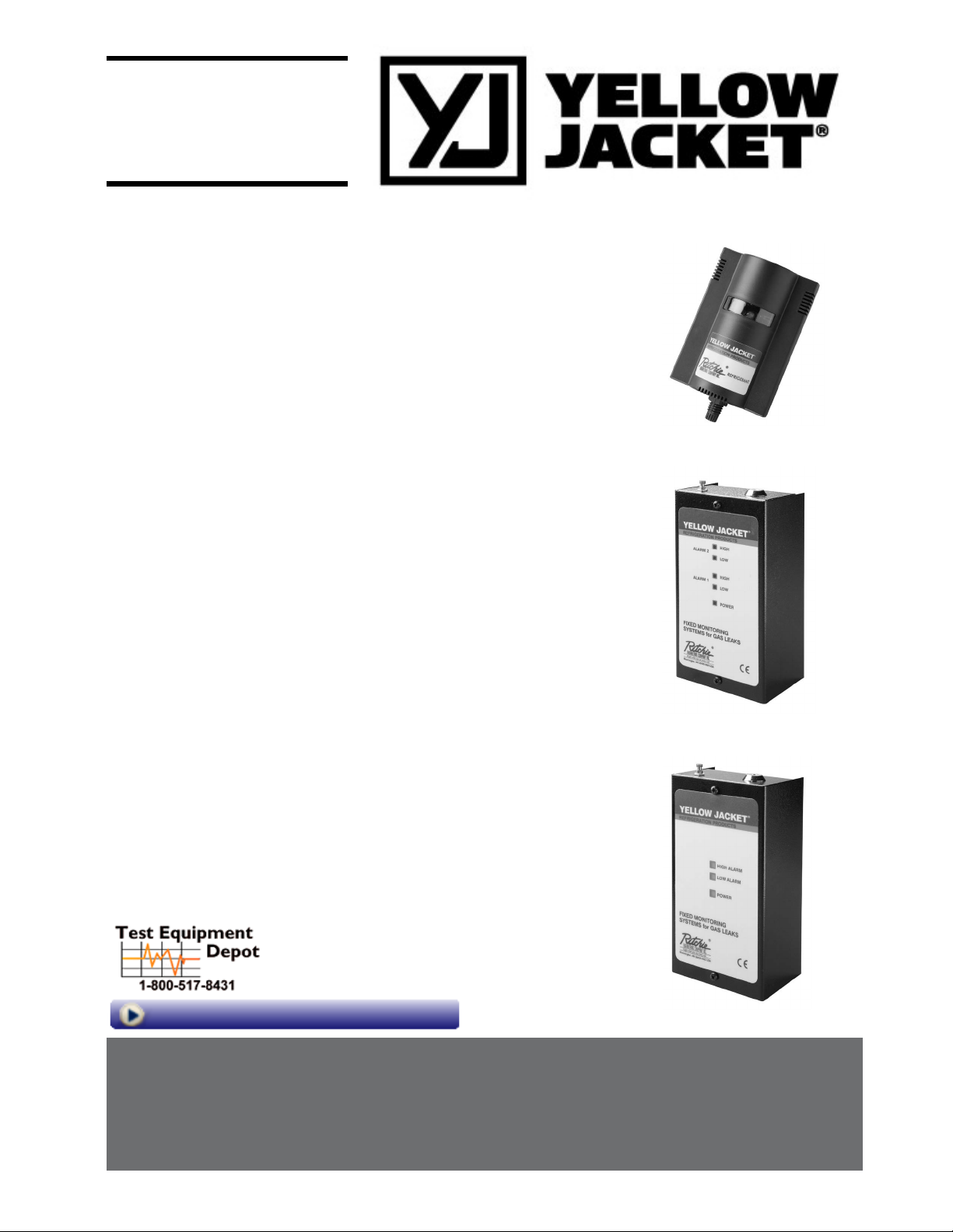
Installation & Operation*
Content Page
1- Installation Instructions
2- Location Instructions
3- Typical Settings
4- Operating Instructions
5- Test/Function Instructions
6- Decorative Remote Sensor Installation
7-
Annual Test
9-
Troubleshooting
10- Installation and Wiring Diagrams
11- Mounting Diagrams
*Technician use only
This unit must be installed by a suitably qualified technican who will install this unit in accordance with these instructions and the
standards set down in their particular industry/country. Suitably qualified operators of the unit should be aware of the regulations and
standards set down by their industry/country for the operation of this unit. These notes are only intended as a guide and the
manufacturer bears no responsibility for the installation or operation of this unit.
Failure to install and operate the unit in accordance with these instructions and with industry guidelines may cause serious injury
including death and the manufacturer will not be held responsible in this regard.
Leak
Monitors
8- Check/Calibration Procedure
Visit us at www.TestEquipmentDepot.com
99 Washington Street
Melrose, MA 02176
Phone 781-665-1400
Toll Free 1-800-517-8431
Page 2
1- Installation Instructions
The main alarm unit and its sensor(s) should be positioned carefully to avoid
mechanical damage (from moving machinery, doors, etc.) thermal extremes
(close to heaters) and should not be placed unprotected in direct strong
drafts/airflows and areas where water or moisture is present unless an
appropriate enclosure is used.
Avoid routing sensor cabling outside of premises, or between buildings via
overhead cables. Also, sensor wiring should be kept a minimum of 500mm
from mains and telephone cables. (See section on sensor location)
When connecting the mains and / or sensor cables ensure a second
mechanical fixing is used. Use a cable tie inside the enclosure within 25mm
of the cable gland.
When power to the unit is switched on, there is a 3-minute delay before the
system activates. This allows the sensors to warm up to the correct
temperature for gas detection. The green light on the alarm panel comes
on after the delay, indicating that the system is ready. When a unit
has been off or stored for a long time the normalising period may be longer
than 3 minutes. After the 3 minutes has expired alarms may activate. You
may deactivate the siren until normalisation is complete. (Key switch).
1.1 Remove the front cover. Mount the control unit using the mounting
holes in the base such that the sensor cable terminal blocks are at the
bottom of the unit in a convenient position (observing the above note).
1.2 Wiring to Remote Sensors:
Connect sensor cable (standard 4 wire alarm cable as specified below) to
sensor terminal block CN1 on control unit positions 1,2,3 & 4. Route
cable through the gland to remote sensor No.1.
relay, and the device to be switched to either the N/O or N/C Terminals of the
volt free relay, depending on whether a 12 Volt output is required during an
alarm condition or while the system is on standby. The return from the device
is connected to OV on CN11
1.4. Voltage Free Relays.
10A @ 120/230 VAC
Two Level Unit: One Level Unit:
1 & 2 Channel Systems: CN5: Low Level Alarm CN4
CN4: High Level Alarm
4 - 6 Channel Systems: CN10: Low Level Alarm CN10
CN9: High Level Alarm
CN12: Fault Reporting Relays
Notes: N/O and N/C refer to contact status in standby mode.
On a two level system, A high level alarm condition on any sensor will
override a low level alarm condition on another sensor.
On 4 - 6 Channel two level units, the high level relay may be set for
normal or Fail-Safe operation by setting jumper JP1 on the control
unit printed circuit board (Refer to Installation diagram)
Connect leads to terminal block for Common (COM) and N/O and/or N/C
connections as required.
1.5. Mains Connection.
Connect mains supply (using 3-core 0.75 mm, Mains Flex for 230V systems
or 3 wire, 18 gauge 0.823mm sq mains flex for 120V Systems) to terminal
block CN3 (on 1 & 2 channel systems), or fused terminal block mounted on
base of control unit (4 - 6 channel systems), Connections L, N and E. Ensure
that earth connections to the lid and base of the enclosure are maintained.
Standard Sensors:
Remove lid of sensor. (To open the sensor enclosure : turn the cable gland ½
turn counterclockwise to loosen the internal nut, depress the clip on top of the
enclosure and open). Connect the other end of the sensor cable to terminal
block CN1 positions 1,2,3 & 4. Mount sensor box. Replace lid. Repeat above
sequence for remaining sensors (depending on supplied system
configuration.) Feed the cable through the bottom of the sensor enclosure.
Please ensure that connections 1 to 4 on the sensor connect to their
corresponding numbers on the terminal block in the main alarm unit,
otherwise the system will not function correctly.
Maximum Sensor Wiring Length: 230V Systems
1 - 2 Channel Standard Units: 40 Metres 7/0.2mm Alarm Cable
(Max. 3.52 Ohms / Core)
4 - 6 Channel Standard Units: 100 Metres 7/0.2mm Alarm Cable
(Max. 8.8 Ohms / Core)
Maximum Sensor Wiring Length: 120V Systems
1 - 2 Channel Units: 60.9M (200 feet) 22 gauge, stranded 4 wire
Alarm Cable (Max 3.52 Ohms/Wire)
4 - 6 Channel Units: 152.25 Metres (500 feet) 22 gauge, stranded
4 wire Alarm Cable (Max 8.8 Ohms/Wire)
You may use different cables and longer distances provided the ohmic
resistance shown is not exceeded.
1.3 External Sounder and uncommitted 12 Volt DC output.
(Applies to 4 - 6 Channel systems only)
12 volt DC Sounder (12V /150MA max) - connect positive lead to CN11
terminal marked +12V, negative to centre terminal marked ‘BUZZ’.
For uncommitted 12 V DC @100mA output is obtained via CN11 Terminals
‘+12V’ and ‘0V’ This output may be wired via the volt free relays to obtain a
switching 12 volt DC output to drive an external relay or solenoid as follows:
If both the buzzer and 12V DC output are corrected correctly they should not
exceed, 250MA in total.
Connect Terminal ‘+12V’ on CN11 to the ‘COM’ terminal of the volt free
NOTE: Connection to mains supply must be via an approved readily
accessible, switched and fused (2 or 5 Amp Fuse) plug and socket or
as per local wiring regulations which should be within 3 meters (10
feet) of the control unit.
• The mains cable used should be of an approved type HAR or
Cenelec approved or locally approved equivalent.
• If replacement of the mains fuse is required use only the
appropriate type from the table below
Control Unit Type: Fuse Rating Sensor Connection Siren /
230V Systems Main Supply Fuse: Auxiallry
1 - 2 Channel Unit: 20mm T50mA Not Applicable Not Applicable
4 - 6 Channel Unit: 20mm T160mA 20mm T250 mA 20mm T315 mA
Control Unit Type: Fuse Rating Sensor Connection Siren /
120V Systems Main Supply Fuse: Auxiallry
1 - 2 Channel Unit: 20mm T100mA Not Applicable Not Applicable
4 - 6 Channel Unit: 20mm T315mA 20mm T250 mA 20mm T315 mA
• The blanking plugs for cable entries should only be removed if being
replaced by cable glands
Ensure that the live and neutral conductors take the strain before the
•
earth conductor.
2. Location Instructions
Location of Sensors
Sensors must be located within the appropriate wire lengths from the central
control unit.
In all cases the sensor supplied is designed for maximum sensitivity to a
particular gas.
However
, in certain circumstances false alarms may be caused by the
occasional presence of sufficiently high concentrations of other gaseous
impurities. If such a situation is likely to arise installers should check with our
Technical Department so that sensor (s) of suitable cross sensitivity can be
supplied. Examples of situations where such abnormalities may arise include.
• Plant room maintenance activity involving solvent or paint fumes or
refrigerant leaks.
230V Fuse
230V Fuse 230V Fuse 230V Fuse
120V Fuse
230V Fuse 120V Fuse 230V Fuse
2
Page 3

• Plant rooms in fruit ripening/storage facilities because of accidental gas
migration (bananas - ethylene, apples - carbon dioxide)
• Heavy localised exhaust fumes (carbon monoxide, dioxide, propane)
from engine driven forklifts in confined spaces or close to sensors.
A response delay is built in to the system to minimise the possibilities of false
alarms.
Machinery rooms
There is NO ABSOLUTE RULE in determining the number of sensors and their
location. However a number of simple guidelines will help to make a decision.
Sensors monitor a point as opposed to an area. If the gas leak does not reach the
sensor then no alarm will be raised. Therefore, it is extremely important to
carefully select the sensor location. Also consider ease of access for maintenance.
The size and nature of the site will help to decide which method is the most
appropriate to use. Locations requiring the most protection in a machinery or
plant room would be around compressors, pressurised storage vessels,
refrigerant cylinders or storage rooms or pipelines. Most vulnerable are valves,
gauges, flanges, joints (brazed or mechanical), filling or draining connections etc
When mechanical or natural ventilation is present mount a sensor in the airflow.
In machinery rooms where there is no discernable or strong airflow then
options are:
• Point Detection, where sensors are located as near as possible to the
most likely sources of leakage, such as the compressor, expansion
valves, mechanical joints or cable duct trenches.
Perimeter Detection, where sensors completely surround the area or
•
equipment.
With heavier than air gases such as halocarbon and hydrocarbon
•
refrigerants such as R404A, propane, and butane sensors should be
located near ground level
• With lighter than air gas e.g. ammonia, the sensor needs to be located
above the equipment to be monitored e.g. on a bracket or high on a wall
within 300 mm of, or on the ceiling provided there is no possibility of a
thermal layer trapped under the ceiling preventing gas reaching the
sensor. (NB. At very low temperatures, such as in a refrigerated cold
store, ammonia gas becomes heavier than air).
• With similar density or miscible gases, such as CO or CO2, sensors
should be mounted about head high – say 1.5m.
• Sensors should be positioned a little way back from any high-pressure
parts to allow gas clouds to form. Otherwise any leakage of gas is likely
to pass by in a high-speed jet and not be detected by the sensor.
• Make sure that pits, stairwells and trenches are monitored since they
may fill with stagnant pockets of gas.
• If a pressure relief vent pipe is fitted to the system, it may be a
requirement to mount a sensor to monitor this vent pipe. It should be
positioned about 2 m above the PRV to allow gas clouds to form.
With racks or chillers pre-fitted with refrigerant sensors, these should be
•
mounted so as to monitor the compressors or if extract ducts are fitted
the air
flow in the duct may be monitored.
Refrigerated Spaces
refrigerated spaces sensors should be located in the return airflow to the
In
evaporators on a sidewall, below head high preferred, or on the ceiling, not
directly in front of an evaporator. In large rooms with multiple evaporators,
sensors should be mounted on the central line between 2 adjacent
evaporators, as turbulence will result in airflows mixing.
• With air-cooled chillers or air-cooled condensers with non-enclosed
condenser sections it is difficult to effectively monitor leaks in the coil
sections. With some designs it will be possible using an airflow sensor
to monitor airflow to the start –up fans in the front or rear sections.
• If there is a possibility of refrigerant leaks into a duct or air-handling unit
install a sensor to monitor the airflow
W
eatherproof sensors should be used for unprotected outdoor applications.
Air Conditioning – Direct systems VRV/VRF
EN378 states that at least one detector shall be installed in each occupied
space being considered and the location of detectors shall be chosen in
relation to the refrigerant and they shall be located where the refrigerant from
the leak will collect. In this case refrigerants are heavier than air and detectors
should have their sensors mounted low .e.g. at less than bed height in the
case of an hotel or other similar Category Class A spaces. Ceiling or other
voids if not sealed are part of the occupied space.
In a hotel room monitoring in ceiling voids would not
strictly comply with EN378
Do’s
Don’ts
• mount the in-room sensor at less than the
normal heights of the occupants e.g in a
hotel room this is less than bed height between 200-500mm off the floor
.
• Do not mount sensors
– under mirrors
– at vanity units
.
– in or near bathrooms
• away from draughts and heat sources like
radiators etc.
• avoid sources of steam
For further detailed Installation tips covering most installations and equipment
types.. chillers, air cooled chillers etc see our web site www.murco.ie.
Perhaps the most important point of all is not to try and economise by
using the minimum number of sensors possible. A few extra sensors could
make all the difference if a gas leak occurs!
3- Typical settings
Gas: Refrigerant R404A Low Alarm Set Point: 100ppm
For a particular unit please refer to the gas settings shown on the rating plate.
4- Operating Instructions
The YELLOW JACKET Gas Monitor having been installed in accordance with the
installation instructions is ready to monitor the chosen air space and detect
gas leaks at the pre-set level.
Each of the sensors has a green light to indicate that power is present.
To minimise false alarms, the system has a built in delay, between the arrival
of gas at the sensor unit, and an alarm occurring. This delay is 20-25
seconds before a low level alarm, and 25-30 seconds on a high level alarm.
High Alarm set Point: 1000 ppm
Chillers
In the case or small water or air-cooled enclosed chiller units mount the
sensor so as to monitor airflow to the extract fans. With larger models also
place a sensor inside the enclosure under or adjacent to the compressors
In the case of outdoor units:
• such as enclosed air-cooled chillers or the outdoor unit for VRV/VRF
systems mount the sensor so as to monitor airflow to the extract fan.
With large units also place a sensor inside the enclosure under or
adjacent to the compressors
In the case of non-enclosed outdoor units
• If there is an enclosed machinery section then locate a sensor there.
• In the case of units with enclosed compressors, mount sensors in the
enclosures
• Where you have protective or acoustic panels mount the sensor low
down under the compressors where it is protected by the panels.
Unit Operation
Idle: Only the green light on the panel is on. No gas is present.
If the green light is off, power to the unit has been interrupted. Refer to the
troubleshooting guide.
Alarm Condition
Low Alarm: One of more yellow lights on the panel turn on. The sounder
operates intermittently, and the low alarm volt free relay
operates: this indicates presence of a low level of gas on one or
more sensors.
High Alarm: One of more red lights on the panel turn on. The sounder
operates continuously, and the high alarm volt free relay
operates: this indicates presence of a high level of gas on one or
more sensors.
3
Page 4

For the purpose of system maintenance, the siren may be disabled
temporarily by using the key-switch.
Low-level alarm conditions will reset automatically when the gas
dissipates. High level alarm conditions require a manual reset (By pressing
the reset button) Please note that a high alarm condition can only be
reset 30-60 seconds after the gas clears from around the sensors.
5- Test / Function Instructions
The unit is calibrated in the factory and does not require to be calibrated on
installation. After installation the units should be bump tested. Expose the
sensors to test gas using test cylinder (appropriate to the installation)
or if not available, crack open the valve of a cigarette lighter (only for
Semiconductor units) without igniting it and hold it over the vent holes on the
upper right side of the sensor. The gas is heavier than air and should fall into
the sensor. This will put the system into alarm. The red LED will light
showing the system is in alarm. The delay will prevent the siren sounding
or relay switching for the preset delay, if delay is set.
With a bump test you can see the functions of the sensor - the yellow/red led
will light, the relay and sounder will function.
To test the siren and or relay function, check the delay is set at zero using the
header as shown on the installation diagram and expose to gas as above.
After the gas has cleared, press the reset button.
Before testing the sensors on site the unit must have been powered up and
allowed to stabilize.
6- Sensor - Annual Test
To comply with the requirements of EN378 and the F GAS regulation sensors
must be tested annually. However local regulations may specify the nature and
frequency of this test. If not the recommended procedure should be followed.
Contact us for details.
Check local regulations on calibration or testing
requirements.
After exposure to a substantial gas leak, sensor should be checked and
replaced if necessary.
7- Check/Calibration Procedure
These units must be checked/tested and/or calibrated by a suitably qualified
technician who must test or callibrate the unit in accordance with the
instructions as provided or set out in the relevant manual and the standards
set down in their particular industry/country. Suitably qualified operators of
the unit should be aware of the regulations and standards set down by their
industry/country for the testing or calibration of this unit. These notes are only
intended as a guide and insofar as permitted by law the manufacturer accepts
no responsibility for the calibration and testing or operation of this unit.
Failure to test or calibrate the unit in accordance with the then applicable
instructions and with industry guidelines may result in serious injury including
death and the manufacturer is not liable for any loss injury or damage arising
from improper testing or calibration or inappropriate use of the unit.
The testing or calibration of the unit must be carried out by a suitably qualified
technician, in accordance with the testing or calibration instructions and in
compliance with locally applicable guidelines and regulations.
4
Page 5
INTRODUCTION
440mm high with flow regulator
The frequency and nature of testing or calibration may be determined by local
regulation or standards.
EN378 and the FGAS Regulation require an annual check in accordance with
the manufacturer’s recommendation.
For 2 level systems,we recommend annual checks by resetting units
electrically to the factory calibration settings and a bump test and
replacement of the sensors with a pre-calibrated certified sensor
every three years. The alternative to replacement is an on-site gas
calibration. Sensor replacement may be more cost effective, eliminate
end of life concerns, and constantly renew the detection system.
If the sensor is exposed to a large leak it should be tested to ensure
correct functionality by electrically resetting to the factory calibration
settings and carrying out a bump test.
There are two concepts that need to be differentiated: bump test and
calibration
Bump Test
: This consists of exposing the sensor to a gas. The objective is to
establish if the sensor is reacting to the gas and all the sensor outputs are
working correctly. A quantified bump test is one where gas of a known
concentration is used.
Calibration
: This consists of exposing the sensor to a calibration gas setting
the “Sensor Standby voltage”, the alarm set points “Alarm Threshold
Voltages”, and checking/adjusting all the outputs, so that they are activated at
the specified alarm gas concentrations when exposed to this gas.
It is required by EN378 to record the check results in the Logbook.
Before you carry out the bump test or calibration:
1- Advise occupants, plant operators, and supervisors.
2- Check if the unit is connected to external systems such
as sprinkler systems, plant shut down, external sirens
and beacons, ventilation, etc. and disconnect as
instructed by the customer.
3- For 1 level systems you must deactivate the 3-min alarm
delay if selected by moving jumper JP1 to “off” position.
For 2 Level systems upon power up there is a delay of 3
minutes before the Green power LED turns on.
4- For Bump Test or Calibration, the units should be
powered up overnight.
5- If a unit has been powered off for a short time, say due to
maintenance, it will normalise within a few minutes. If
sensors have been in long-term storage or the detectors
have been turned off for a long period, normalisation
would be much slower. However within 1-2 hours
sensors should have dropped below the low alarm level
and be operational. You can monitor normalisation
progress exactly by monitoring the sensor output, see
Table 1, page 5.
2. Electrical reset / bump test (every year)
Electrical reset is based on the calibration information found on the label on
the side of the enclosure and is unique to that sensor.
Tools required:
1- A voltmeter– crocodile clips recommended
2- Factory set point electric values as shown on the rating label
3- Estimate 10 min per sensor
Reset, if necessary, the Standby and low /high Alarm Threshold Voltages to
the factory settings as shown on the calibration label. This is performed on
the sensor PCB.
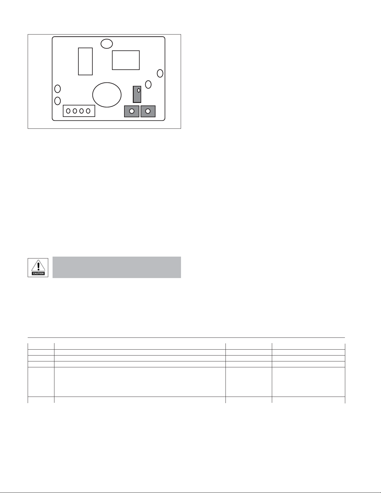
For Standby voltage, connect your DC voltmeter between TP5 (0V) and TP4
(+V) as shown in Diagram 2 and adjusting pot RV1.
For low-level alarm voltage, connect your DC voltmeter between TP5 (0V)
and TP2 (+V) as shown in Diagram 2 and adjusting pot P8.
For high-level alarm voltage, connect your DC voltmeter between TP5 (0V)
and TP1 (+V) as shown in Diagram 2 and adjusting pot P7.
If the factory set point information is not on the calibration label (as with
older units) check the serial number of your gas detector on the rating label
and sensor PCB and contact us for the appropriate set point values.
3 BUMP TEST
Ideally bump tests are conducted on site in a
clean air atmosphere.
3.1 Semiconductor and IR sensors for
hydrocarbons:
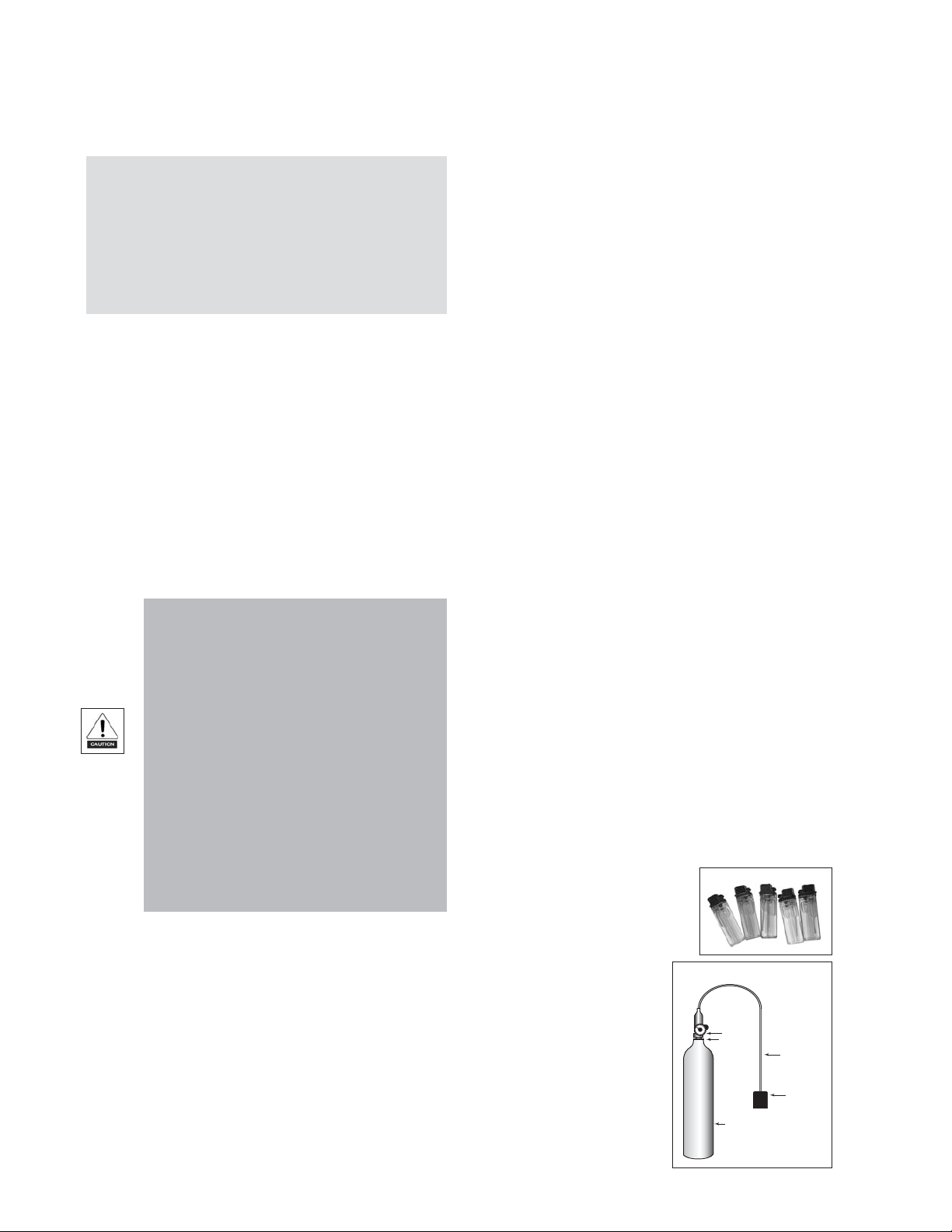
calibration gas at known
We offer cylinders of
Calibration Cylinders
concentration and ampoules for
ammonia (NH3) at 100ppm and
1.000 ppm and using these
constitute a quantified bump test.
If Calibration Gas is not available
you can carry out a non-quantified
bump test using a gas cigarette
lighter. By cracking the valve open
without igniting the gas, you
release the gas onto the sensor and
force it into alarm. Check that
alarm lights and relays are activated
Flow
Regulator
Typical Flow
0.3L/Min
Outlet 5/8’’
18 UNF
(C10)
Cylinder
360mm high x 88mm diameter
110L capacity of calibration gas
Weight 1.4 kg
Flexible nonabsorbant
tubing
Vented
Calibration
Hood
Page 6
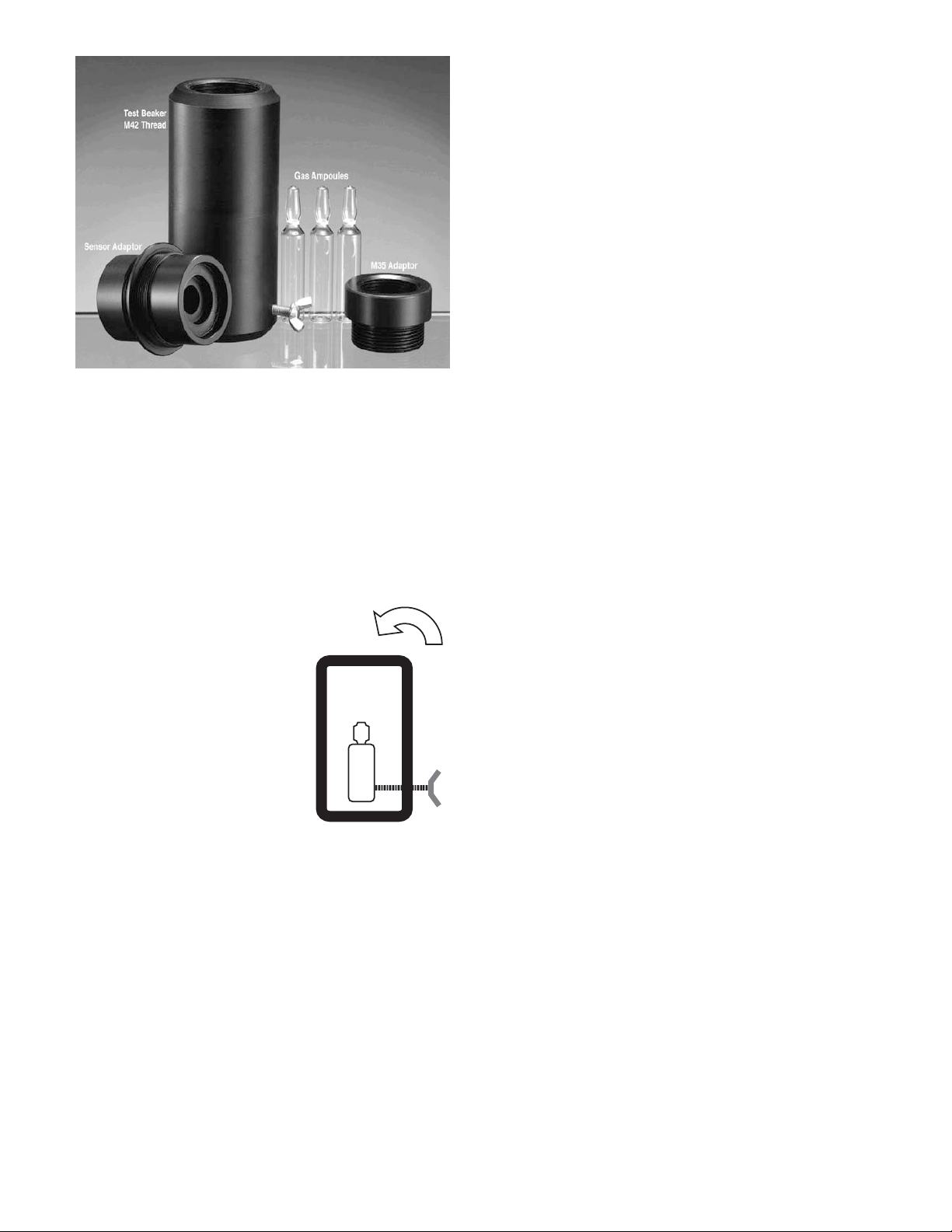
3.2 Bump test using gas ampoules:
1- Make sure that both the ampoules
and the calibration beaker are clean
and dry.
2- Unscrew the beaker hold screw and
place the ampoule so that is sits in
the base of the beaker. As per
illustration.
3- Tighten on the screw ampoule
without breaking it.
4- Remove the enclosure lid of the gas
sensor (not in Ex area and in one
level units as monitoring of voltage
can be done on controller).
5- Connect volt meter for 1 level unit. On the channel undertest between
Pin 4 and Pin2 and for 2 level semiconductor between TP5 and TP4.
For IR boards between OV and VS to monitor sensor response
6- Place the beaker over the sensor head (using an adaptor if required)
or, if an Exd or Remote sensor head version, M35 or M42 thread,
screw the beaker on the remote sensor head. It should be as tight a
fitting as possible to allow maximum exposure to the gas.
7- Tighten on the ampoule until it shatters allowing the content to
diffuse in the beaker. It should be left in place for approximately 5
min.
8- Voltage output will increase. This confirms that the sensor is
responding. In the case of ampoules a response equivalent to 50% or
greater of the ampoule concentration will be satisfactory.
9- Carefully remove any ampoule remains from the gas detector.
Connect the voltmeter for 1 level unit. On the channel undertest between
Pin 4 and Pin2 and for 2 level semiconductor between TP5 and TP4. For
IR boards between OV and VS to monitor sensor response.
Expose the sensor to gas from the cylinder. You can place the entire
sensor into a plastic bag or use a plastic hose/hood to direct gas to the
sensor head.
4 CALIBRATION (every three years)
The alternatives we describe are:
4.1 Exchanging the sensor board – available for 2 level units and 1+2 level IR
units.
4.2 Gas Calibration
4.1 EXCHANGE SENSOR BOARD – available for 2 alarm level system and
1+2 level IR units (every 3 years)
We recommend exchanging your sensor PCB for a newly pre-calibrated
certified unit every 3 years.
Tools required:
1- A pre-calibrated sensor board
2- A voltmeter – crocodile clips recommended
3- Estimate 10 min per sensor
In this case you need to:
1- Power off the unit and remove lid of sensor enclosure.
2- Note the colour code of the cable in positions 1,2,3,and 4 of the
connector block.
3- Undo the cable and 2 screws securing sensor board and remove.
4- Fit the new pre-calibrated sensor and reconnect the cable in the correct
colour sequence at positions 1,2,3 and 4.
5- Power on the unit and allow to stabilise for 15 min.
6- Check voltage readings on positions 1,2,3, and 4 as per procedure in
Table 1, page 5, to ensure that wiring is correct. Note also in the table
how to monitor the sensor as it normalises.
7- Carry out a bump test to confirm the sensor is responding.
8- Keep records of the test date, sensor serial number, and any
observation.
There are a number of advantages to sensor exchange. It is simpler and
quicker than gas calibration. We guarantee the correct calibration and
functioning of the new sensor, which is supplied with a calibration certificate
and finally, you won’t face any problems of sensor deterioration or end-oflife.
4.2 GAS CALIBRATION
This is the adjustment of the gas detector using calibration gas.
We offer a calibration kit that consists of a Calibration gas cylinder
and a flow regulation valve with flexible non-absorbant tubing and vented
calibration hood.
In some cases this option may be expensive relative to sensor exchange
because of the cost of visiting a site, calibration gas and valve, and a
surcharge on the freight cost of the calibration gas as it is classified as a
hazardous substance (ampoules are not classed as hazardous).
The procedure involves electrical set-up followed by adjustment using
calibration gases.
Equipment required:
1- Gas cylinders with the appropriate calibration gas concentrations
2- Gas canister with zero air to calibrate /check the Sensor Standby
Voltage, required if the sensor environment is not clean.
3- Flow gas valve – rate 0.3L/min
4- A voltmeter
5- Estimate 30 min per sensor
The procedure differs slightly depending on the number of alarm levels.
3.3 Bump Test Using Gas Cylinders.
Remove the enclosure lid of the gas sensor (not in an Ex area) and
controller (non applicable to Exd Remote sensor and vent pipe model, 1L
units as monitoring of voltage can be done on controller).
Page 7
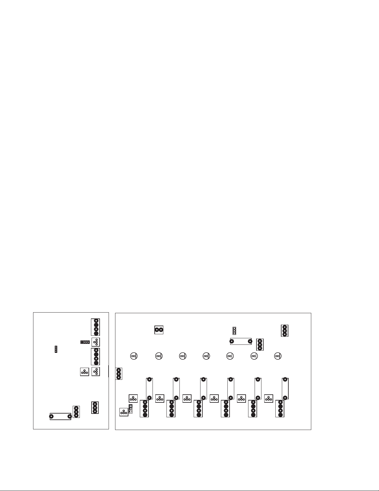
4.2.2 Gas Calibration TWO ALARM LEVELS UNITS
CN10
M
The delay on a 2L system is approximately 25 seconds and cannot be
deactivated.
All adjustments are performed on the sensor PCB and there are three
elements to be adjusted: the Standby Voltage and two Alarm Thresholds.
a. Sensor Standby Voltage (SSV)
The factory settings are shown on the calibration label on the side of
the enclosure.
Connect the voltmeter between TP5 (0V) & TP4 (+Ve) and adjust pot
RV1 for 0.3V (on IR units SSV is fixed).
This value should be already set correctly unless age or background
has caused drift.
b. Alarm Threshold Voltage (ATV)
Low Threshold:
Connect voltmeter between TP5 (0V) & TP2 (+Ve)/0V and low for IR
units, set the voltage as shown on the calibration label by adjusting pot
“P8”.
High Threshold:
Connect voltmeter between TP5 (0V) & TP1 (+Ve)/0V and high for IR
units, set the voltage as shown on the calibration label by adjusting pot
“P7”.
Remember there is an inbuilt delay response to an alarm of approx.
25 sec on both alarm levels.
Monitor voltage between TP5 (0V) & TP4 (+Ve)/0V and VS on IR units.
Apply the low concentration calibration gas to the sensor and wait until
the sensor output signal stabilises. Record this voltage. Apply the
high concentration calibration gas to the sensor and wait until the
sensor output signal stabilises. Record this voltage.
Diagram 1
If the voltages recorded for the low and high alarms differ from the
factory settings shown on the calibration label then adjust P8 and P7
as above to the new values. Record and use these new values for
subsequent electrical set-ups.
The High threshold voltage must be set higher than the low XXX?
1
2NC
2
3
4
ON
1PJ
OFF
FS1
LAC
C
1
2
3
4
3P
4NC
E L N
Diagram 1
12V AC
2P
LD1 LD11 LD21
1P
N/O
CDM
N/O
P1
P7
CN8
1SF
CN1 CN2
1 2 3 4
P2
LD31 LD41
2SF
1 2 3 4
3SF
CN3
1 2 3 4
P4
P3
CN4
Delay
ON
P1
OFF
FS8
4SF
1 2 3 4
P5
+12V
Buzz
2V
CN9
LD51 LD61
5SF
1 2 3 4
P6
CN5
CN6
N/O
CD
N/O
6SF
1 2 3 4
MGD 1 or 2 channel unit. MGD 4 or 6 channel unit.
Page 8
T
T
P1
Diagram 2: Two Level Sensor
P4
P5
4 3 2 1
SEN
LED
RV1
P8 P7
TP2
Two Level Systems
You should adjust the relevant alarm threshold upwards in 0.2Volt
increments until the condition clears.
T
5.2 DOUBLE CHECK CONNECTIONS ARE CORRECT :
To make sure the gas detectors are wired up correctly you can check the
voltages at the sensor cable terminal blocks on the controller PCB or
sensor PCB using a 0-10V voltmeter as outlined below in Table 1.
Place the negative probe on terminal position 4 and with the positive on
1, 3, 2, check the Volts values. The readings are lower at the sensor due
to power drop in the line.
The terminals should have the under listed values:
threshold, or the unit will not function correctly.
threshold, or the unit will not function correctly.
5- ADDITIONAL RECOMMENDATIONS
5.1 FALSE ALARMS : If false alarms are being triggered by background gases,
paint fumes, etc, or extreme humidity or temperature conditions, you
may adjust the settings to compensate.
Table 1. Connections correct values
Position At the Sensor Controller Without Sensor Fitted
Number
4 Is the negative side of the power supply Negative Negative
1 Power Supply 7.2V minimum reading, unless you have power drop reduction. +10V +12-15V
3 Approximately 4-5V +4.8-5V +5V
2
* The voltage signal from the sensor will on power up start high and gradually fall (in clean air) to the SSV value shown on th e calibration label. IR unit will display
0Volts until the 2 minute warm-up has finished.
You can monitor this as follows:
Two level system - typical Internal reference values, approximately +0.4V Sensor in standby
+1.6V Low Alarm Condition
+2.8V High Alarm Condition
2 level systems: Connect voltmeter and monitor voltage between TP5 (0V) & TP4 (+Ve). For IR monitor between OV and VS.
Page 9

8 - Troubleshooting
Alarm Panel:
Symptom: No lights displayed on panel.
Cause: 1. Power failure (check supply)
Symptom: Red Light is on, but no alarm condition is active. i.e No siren and
Cause: 1. Make sure the siren has not been deactivated (Key switch).
Sensor:
Symptom: Green light on sensor is off.
Cause: This may indicate a wiring fault between the controller and sensor
2. Tripped circuit breaker or blown fuse on electrical supply
2. Blown fuse at the electrical supply on the controller PCB board.
3. Has unit warmed up? (This takes 3-4 minutes after power is
switched on.)
no relay operation after 3 minutes.
2. This indicates a wiring or sensor fault (call service provider).
If these are in order the calibration pot may have been adjusted
and may need to be reset. Check with us for instructions.
or a sensor fault. Check power supply to the controller. Check
connections between the controller and the sensor to ensure that
the wires from positions 1 to 4 on the sensor are connected to the
corresponding 1-4 on the controller. (See “Wiring Remote Sensors).
On a 4 to 6 channel unit check that the sensor fuse on the
particular sensor connection position in the controller is not blown.
If the fault is not cleared then the sensor has been damaged.
If you experience spurious alarms in the absence of a leak, contact
us for instructions and support.
4
Page 10
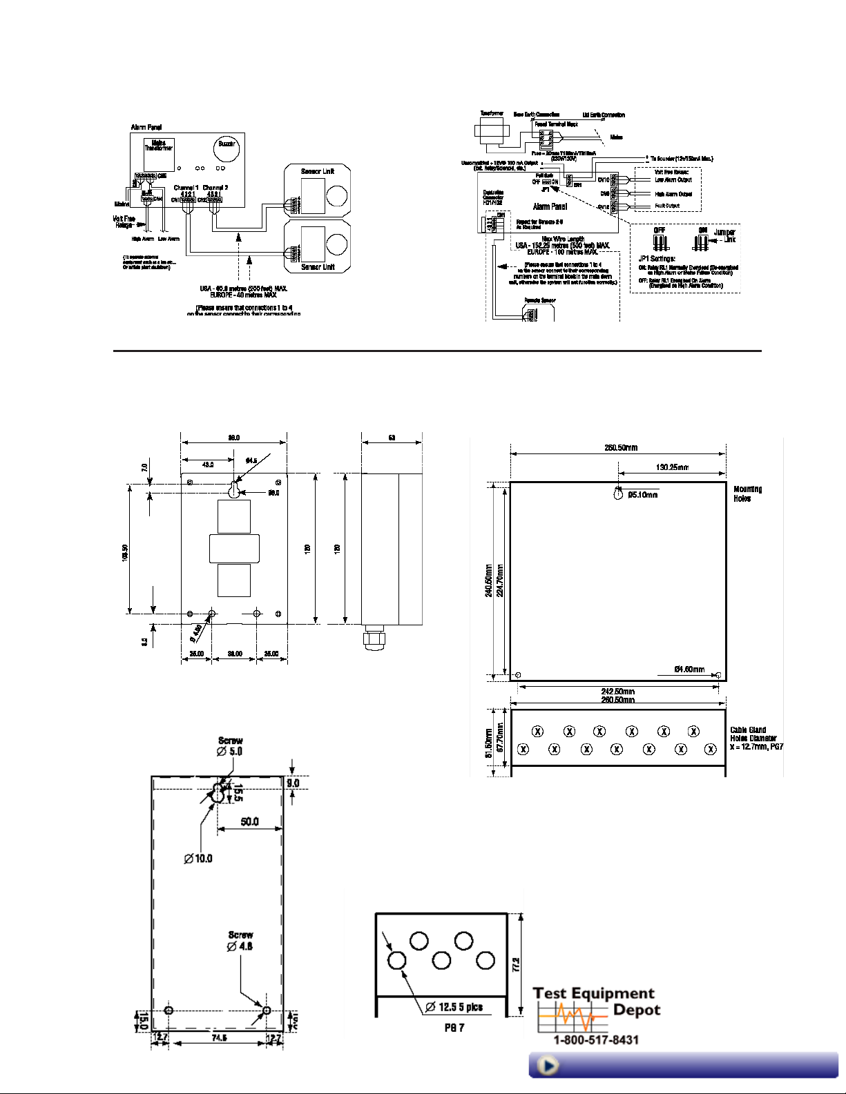
9- Installation and Wiring Diagrams
1, 2 Sensor 2 Level Installation Diagram
10 - Mounting Diagrams
Standard Sensor
4, 6 Sensor 2 Level Installation Diagram
4,6 Sensor Controller Enclosure
Relay Expander Box
1,2 Sensor Controller Enclosure
99 Washington Street
Melrose, MA 02176
Phone 781-665-1400
Toll Free 1-800-517-8431
Visit us at www.TestEquipmentDepot.com
 Loading...