

Page 1

YASNAC PC NC
Maintenance Manual
Page 2

Contents
Chapter 1: General Installation and Electrical Connection ................... 1-1
1.1 Component Arrangement............................................................ 1-1
1.2 General Specifications ................................................................ 1-5
Chapter 2: Routine Inspection ............................................................... 2-1
2.1 Routine Inspection ...................................................................... 2-1
2.2 Battery......................................................................................... 2-1
2.3 Servo Motor ................................................................................ 2-3
2.4 Fan .............................................................................................. 2-4
2.5 Touch Screen .............................................................................. 2-5
2.6 Control Panel .............................................................................. 2-6
Chapter 3: Maintenance Instruments..................................................... 3-1
Chapter 4: Troubleshooting ................................................................... 4-1
4.1 Maintenance Data ....................................................................... 4-1
The VS-626M5..................................................................................... 4-80
4.2 Notes For Safe Operation ......................................................... 4-80
4.3 Receiving .................................................................................. 4-86
4.4 Installation ................................................................................ 4-90
4.5 Wiring ....................................................................................... 4-93
4.6 Operation ................................................................................ 4-128
4.7 Digital Operator ...................................................................... 4-133
4.8 Maintenance And Inspection .................................................. 4-147
4.9 Troubleshooting ...................................................................... 4-149
Chapter 5: Adjustments ......................................................................... 5-1
Page 3

Chapter 6: Module/Unit Replacement ................................................... 6-1
6.1 CPU Rack ................................................................................... 6-1
6.2 CRT Display Unit....................................................................... 6-8
6.3 Floppy Disk Drive Unit ............................................................ 6-17
6.4 NC Power Supply ..................................................................... 6-18
6.5 Handheld Remote Machine Pendant......................................... 6-19
6.6 Noise Filter ............................................................................... 6-20
Chapter 7: Memory Option.................................................................... 7-1
7.1 Part Numbers .............................................................................. 7-1
7.2 RAM DIMM Installation ............................................................ 7-1
Chapter 8: Fixed File Operations............................................................ 8-3
8.1 NC Data Handling ...................................................................... 8-3
8.2 Yasnac PC NC CPU Rack BIOS Setup .................................... 8-59
8.3 PLC Label in Diagnosis and Parameter Screens ...................... 8-69
8.4 CNC Card Software Update ..................................................... 8-72
8.5 Manual Page Customization ..................................................... 8-82
8.6 Properties File Customization................................................... 8-84
Page 4
Chapter 1: General Installation and Electrical Connection PC NC Maintenance Manual
Chapter 1: General Installation and Electrical Connection
This section addresses the basic system: configuration, specifications, enclosure design,
electrical connections, and installation.
1.1 Component Arrangement
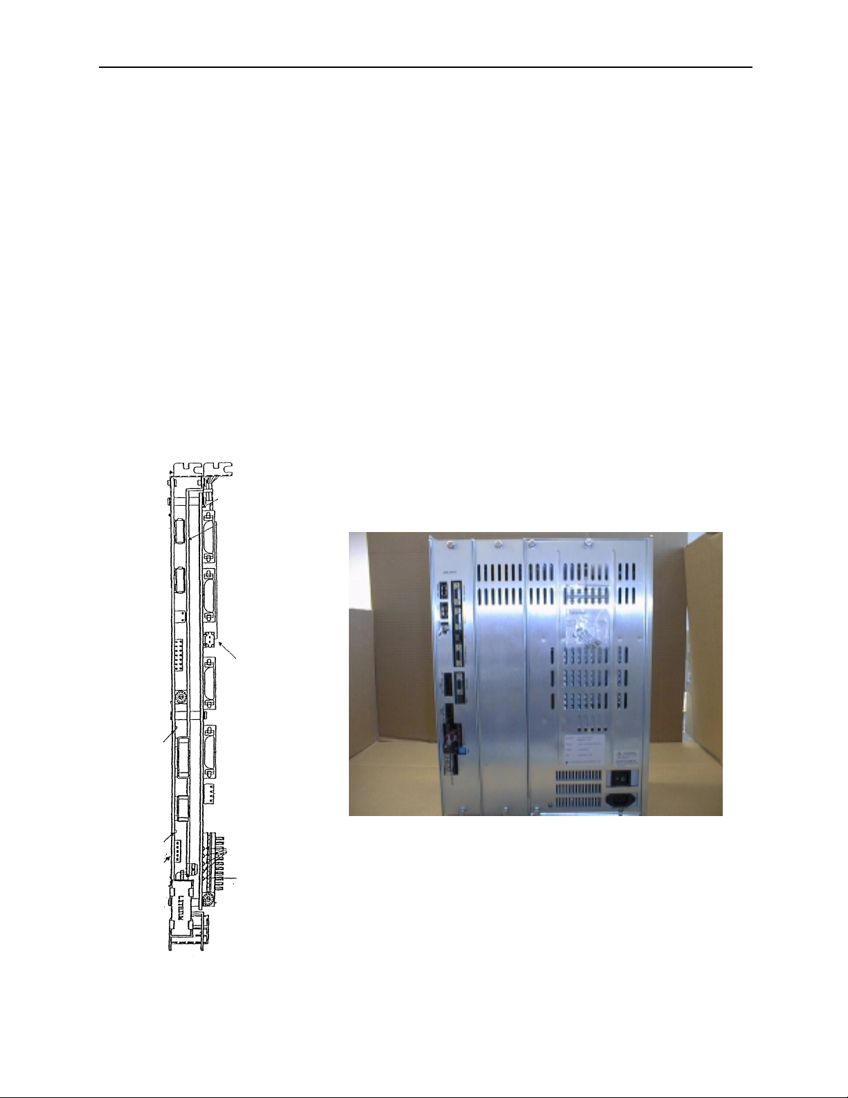
The YASNAC PC NC unit is composed of two boards: JCP20 and JFC20
(JZNC-JFC10). (Refer to the figure below.) The PC NC unit is inserted
into a PC extended bus (ISA) inside the personal computer (PC) case. The
I/O module, servo unit, spindle drive, and motor are the same as those of
the YASNAC J100 CNC UNIT.
Figure 1.1: The YASNAC PC NC Unit
1-1
Page 5
PC NC Maintenance Manual Chapter 1: General Installation and Electrical Connection
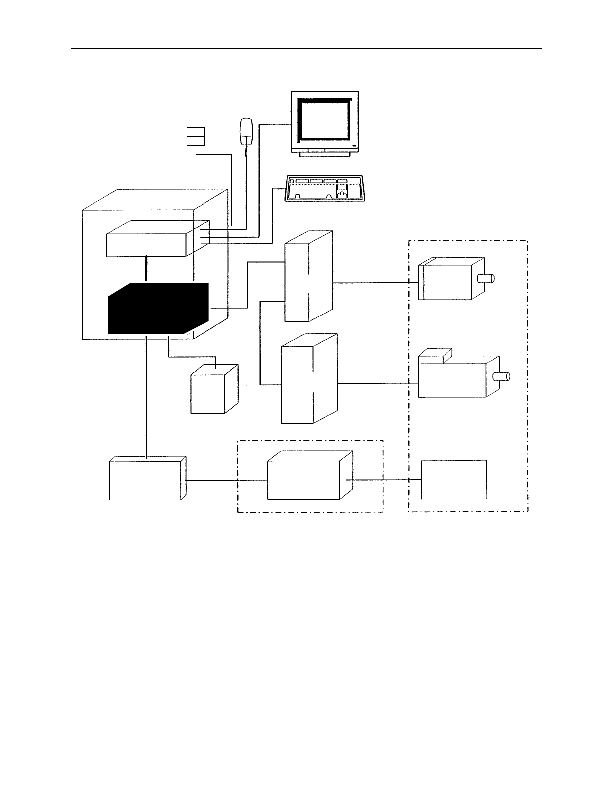
FDD
PC NC case
PC
ISA bus
JFC10
DC
+24V
power
Mouse
Monitor with Touch screen
Keyboard
Feeding
servo unit
Spindle
drive unit
Machine
Feeding
motor
Spindle motor
I/O Module
Figure 1.2: The YASNAC PC NC System Structure Diagram
High voltage
1-2
Device
on
machine side
Page 6

Chapter 1: General Installation and Electrical Connection PC NC Maintenance Manual
CPU RACK UNIT
ATX
MOTHER
BOARD
IDE I/F
KBD
COM2
FDD
COM1
PS/2 MOUSE
LPT1
PCI
ISA
FAN1
CPU
FAN
FAN3
Connection Between Devices
DATA
HDD
PWR
DC
OUT
VIDEO
CARD
VIDEO
JFC20
JCP20-1
PC POWER
CASE FAN
SUPPLY
INPU T
CN01
CN02
CN03
CN04
CN05
CN11
CN12
CN13
CN14
OUTOUT
(PO W E R
SIGNAL)
NC POWER
SUPPLY
INPU T OUTPUT
PGS
GOOD
24VDC FOR
MACHINE I/O
CN1~6
I/O BOARD
FOR MACHINE SIGNAL
(FC8 X X )
CN11
CN13
SENSOR SIGNAL
CONVERTER UNIT
5CN
CRT
KEYBOARD
MOUSE
FDD
TS
CONTROL
SERVO ON
SHUT DOWN
MACHINE
CONTROL
SIGNALS
CN14
CN12
SERVO UNIT
SG DC -**A J A
4CN
1CN
Z AXIS
52CN
51CN
SG DC -**A J A
4CN
1CN
Y AXIS
52CN
51CN
SG DC -**A J A
4CN
1CN
X AXIS
52CN
51CN
C1MR-M5N
4CN
1CN
52CN
51CN
C1MR-MR5N
PWRDATA
TOUCH
SCREEN
MACHINE OP. PANEL I/O
CN5
I/O BOARD
FOR MACHINE
OP. PNL.
(JSP02/04)
CN3
3CN
2CN
3CN
2CN
3CN
2CN
2CN
REACTOR
R/S/T
A1/A2
X0100**
TB3
CN1
CN7 ,8,9
MACHINE PANEL
M
PG
M
PG
M
PG
UAASK*-**FZ*INVERTER UNIT
M
PG
SIGNALS
SGMG-
**A2AB*
FA
HPG
N
INPUT POWER UNIT
AC230V
NFB
TB2
TB1
SVM
SVM
A1/A2
Figure 1.3: Detail Connection of PC NC Unit With Various Devices.
1-3
Page 7

PC NC Maintenance Manual Chapter 1: General Installation and Electrical Connection
Connector Layout NC Side
The following figure provides a detailed Connectors Layout of the YASNAC JZNC-JFC10 board.
Servo controller connector (CN01)
I/O module connector (CN02)
Power good signal connector (CN03)
Interruption setting short pin (S11)
emory address setting rotary swi t ch (S12)
I/O module power output verification LED
I/O module power output connector (CN04)
Servo controller I/O connector (CN11)
Power On/Off co nne cto r (C N12)
Fuse (HM03, 0.3A) (F1)
RS232C connector (CN14)
Direct IN/OUT connector (CN14)
System load switch (S1)
I/O module power input connector (CN05)
I/O module power input verification LED
ttery power reply supply connector (CN06)
Battery
Figure 1.4: Detailed Layout of the YASNAC JZNC-JFC10 Board
System load switch (S1)
(from top: 1, 2, 3, 4)
Battery alarm LED
LITHIUM
System load rot ary switch (S1)
1-4
Page 8
Chapter 1: General Installation and Electrical Connection PC NC Maintenance Manual
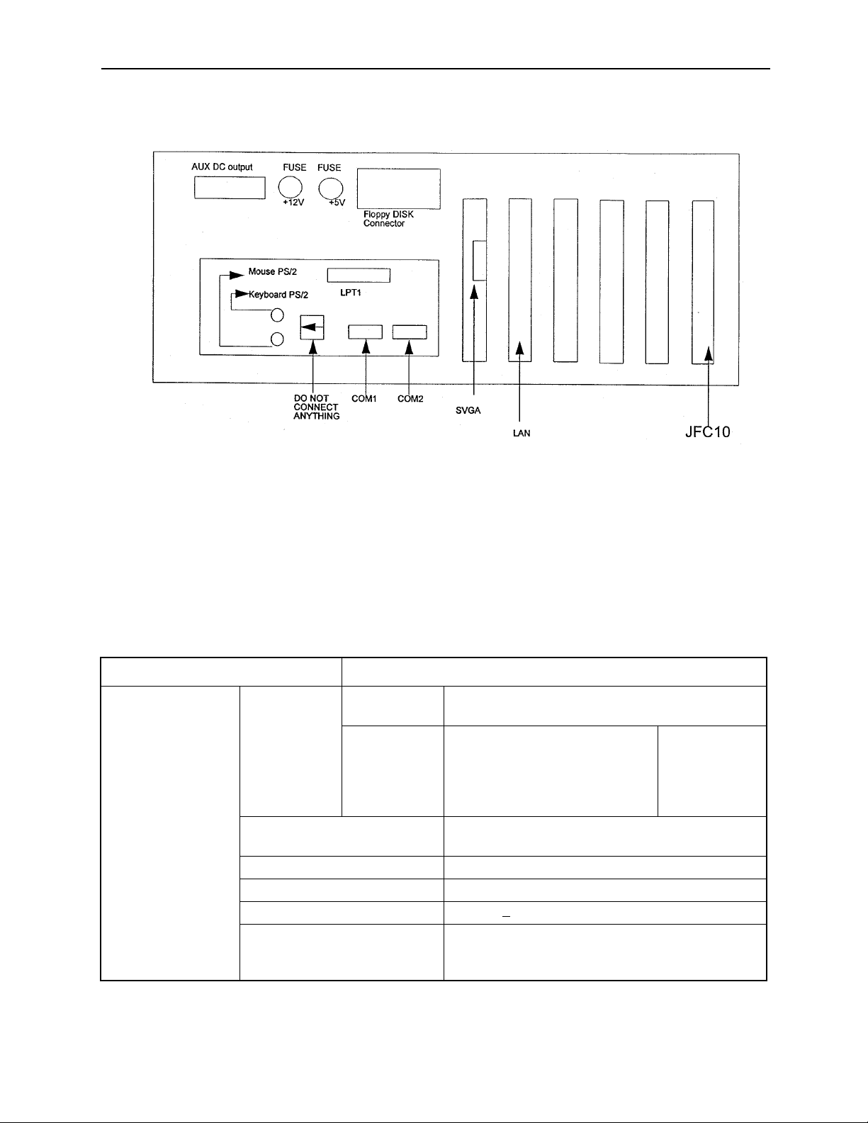
Connector Layout (PC Side)
Figure 1.5: Connector Layout of the PC NC CPU Rack (top view)
1.2 General Specifications
The enclosure must be designed to meet all of the following conditions.
Table 1.1: Specifications
Item Specifications
Ambient Conditions Temperature* Storage and
Transportation
Operating
(around
enclosure)
Humidity 20% to 80% RH (with operation)
Vibration during operation Less than 4.9m/s
Others Free from dust, coolant, or organic solvent
PC NC Unit input power supply +24VDC+
Power Supply Unit
UPS000004
o
-15
C to +65oC
PC NC unit
I/O module
Servo Amplifier
14” Color monitor with touch
screen
10% to 90% RH (with non-operation)
10% 180V-264VAC
Input power supply voltage: 180V ~ 264VAC
Frequency: 47Hz to 63Hz
Momentary interruption: 0.5 cycle (0VDC)
o
0
C to +53oC
Note: Avoid installing the control panel in a location subject to direct sunlight, near heat generating
1-5
Page 9

PC NC Maintenance Manual Chapter 1: General Installation and Electrical Connection
devices, or outdoors, even if the ambient temperature is within the specified range.
Design of the enclosure should be made on the basis that the average temperature
increase of air within the enclosure (containing the PC NC unit and other compo-
nents) should be 10oC below the external air temperature.
(1) Temperature Increase within the Enclosure (Average Temperature Increase)
The internal temperature increase (sheet metal enclosure) is generally as follows: where,
∆Τ: Internal temperature increase (oC)
P: Heat generation in enclosure (W)
qe: Enclosure heat percolation ratio (W/oC)
k: Heat transit ratio of sheet metal (W/m2oC)
6W/m2oC: With internal cooling fan
4W/m2oC: Without internal cooling fan
A: Efficient heat diffusion area of enclosure (m2)
Area capable of diffusing heat in surface area of the enclosure
(Excluding area contacting other devices)
Example: Allowable heat generation in the enclosure with internal circulating fan
1200
All dimensions in millimeters
800
700
Figure 1.6: Enclosure Dimensions
Efficient heat diffusion area is independently located, so bottom area is
excluded.
A=4.16m
2.
If the heat generation in the enclosure is supposed to be 246W (113W in the
1-6
Page 10

Chapter 1: General Installation and Electrical Connection PC NC Maintenance Manual
CNC portion, 104W in the servo portion, and 29W in the I/O portion):
P
∆Τ=
P
=
qe
246
6 x 4.16
.
k A
= 9.9 (oC)
Therefore, the above value is within the temperature increase value.
When it exceeds 10oC, separate cooling countermeasures must be arranged.
(2) Heat Exchanger Cooling Capacity
Yaskawa can provide heat exchangers where the cooling capacity is insufficient even with a circulating fan mounted in the enclosure.
Table 1.2: Heat Exchangers
Heat Exchanger Cooling Capacity External Dimensions (mm)
REX1550
HEATEX02
100W /10
250W /10
o
C
o
C
295 width x 890 height x 50 depth
440 width x 924 height x 50 depth
The heat generation indicated in the above table is the allowable heat generated
when the internal temperature increase in the enclosure is limited to under
10oC.
1-7
Page 11

PC NC Maintenance Manual Chapter 1: General Installation and Electrical Connection
Example: Allowable Heat Generated in the Enclosure with Heat Exchanger
The amount of internal heat generated to make the internal temperature under
10oC when the enclosure is equipped with a HEATEX02 Heat Exchanger is
expressed by the following equation:
.A.
P= k
∆Τ+ 250 W/10oC
= 6 x 4.16 x 10 + 250
= 499 W/10
o
C
Therefore, the amount of internal heat generated must be less than 499W.
(3) Mounting Heat Exchanger
The heat exchanger must be mounted on the enclosure provided by the
machine tool builder, as shown in the figure below. Mount the exchanger so
that the internal air is drawn from the upper portion and discharged through the
lower portion, while the external air is drawn in from the lower portion and discharged through the upper portion.
Internal air
Enclosure
External air
Heat exchanger
Figure 1.7: Mounting of Heat Exchanger on the Machine Builder’s Enclosure
1-8
Page 12

Chapter 1: General Installation and Electrical Connection PC NC Maintenance Manual
(4) Heat Generation by Respective Units
Table 1.3: Heat Generation
Unit Type
PC NC rack JZNC-JPCRKM_-_ — — —
14” Color CRT with
Touchscreen
I/O Module JANCD-FC810* 29 29 0
Converter CIMR-MR5N23P7 84 44 2.5
Spindle Inverter CIMR-MR5N23P7 84 44 2.5
Reactor UZBA-B 20A 0.53 mH 35 35 0
JZNC-JPCOP-_ _ _ — — —
JANCD-FC860* 29 29 0
JANCD-FC861* 14.5 14.5 0
CIMR-MR5N25P5 84 44
CIMR-MR5N27P5 119 61
CIMR-MR5N2011 152 70
CIMR-MR5N2015 204 88
CIMR-MR5N2018 273 108
CIMR-MR5N2022 335 132
CIMR-MR5N2030 392 160
CIMR-MR5N25P5 185 58
CIMR-MR5N27P5 244 77
CIMR-MR5N2011 307 89
CIMR-MR5N2015 454 119
CIMR-MR5N2018 565 144
CIMR-MR5N2022 717 180
CIMR-MR5N2030 869 219
UZBA-B 30A 0.35 mH 45 45 0
UZBA-B 40A 0.265 mH 50 50 0
UZBA-B 60A 0.18 mH 65 65 0
UZBA-B 80A 0.13 mH 75 75 0
UZBA-B 90A 0.12 mH 90 90 0
UZBA-B 120A 0.09 mH 90 90 0
UZBA-B 160A 0.07 mH 100 100 0
Total Heat
Generation (W)
Internal Heat
Generation (W)
Minimum Wind
Velocity for
Cooling
1-9
Page 13

PC NC Maintenance Manual Chapter 1: General Installation and Electrical Connection
Table 1.3: Heat Generation (Continued)
Unit Type
SGDC-05AJ A 28 10 2.5
SGDC-10AJ A 48 12
Servo Unit
SGDC-15AJ A 73 15
SGDC-20AJ A 108 18
SGDC-30AJ A 148 22
SGDC-50AJ A 208 28
1. The heat generated by the CNC unit varies depending on the addition of
options. The heat generated by the I/O module varies with I/O status.
2. Internal heat generation is the heat remaining inside of the enclosure when the
fin of the servo is exposed outside of the enclosure, and when the external air is
applied to the fin at greater than 2.5m/s
3. The thermal design of the enclosure to house the servo unit varies with
machine specifications, but is acknowledged to use a value of 70% of the load
factor.
Total Heat
Generation (W)
Internal Heat
Generation (W)
Minimum Wind
Velocity for
Cooling
1-10
Page 14

Chapter 2: Routine Inspection PC NC Maintenance Manual
Chapter 2: Routine Inspection
This chapter includes the requirements to maintain optimum operating conditions over
time.
2.1 Routine Inspection
The table below details routine inspection of the PC NC.
Table 2.1: Routine Inspection
Area Inspect Item Frequency
Battery Verify battery alarm
LED is on.
Servo motor Vibration and noise Daily ON Feel by hand; listen by ear.
Motor contamina-
tion and damage
Fan Air flow Monthly ON and OFF Feel by hand; listen by ear.
Touch screen Clean Daily ON and OFF Use clean rag.
Calibrate Monthly ON Use Calibration Screen.
Control panel Verify doors are
tightly closed.
Verify tight fit, no
gaps in the side
plates, and door
gaskets are not
worn.
* With the exception of inspections made while the NC is in the energized state (i.e., external cleanliness,
vibration, noise, etc.) , turn of f the source p ower suppl y to the NC before undertaking routine maint enance
service. To remove power completely from the NC, turn off the main circuit breaker on the power panel
of the machine.
At power on ON If alarm LED is on, replace battery.
Daily (or as
required)
Daily OFF Visual inspecti on
Monthly OF F Visu al ins pe ction
System
OFF/ON*
ON and OFF Visual inspection
Remarks
2.2 Battery
To determine whether the battery must be replaced, and replacement directions,
follow the steps below.
1. Press the Power OFF button.
2-1
Page 15

PC NC Maintenance Manual Chapter 2: Routine Inspection
2. Turn OFF the door interlock switch, if provided. (The power can be turned ON
with the door open.)
3. Open the door to view the NC rack.
4. Turn the power ON. If the Battery Alarm LED is displayed in the Message Bar
on the top portion of the screen, the battery must be replaced within 16 hours.
Do not use commercially-available batteries. Contact a Yaskawa customer service representative.
5. If the battery must be replaced, turn the power OFF. Remove the battery from
the battery holder.
6. Place the new battery in the holder and set the connector. (Note: the direction
of the connector is unimportant; however, poor connection may result in a lack
of conduction.). Refer to the figure below.
Correct Correct Incorrect
Figure 2.1: Battery Connection
Figure 2.2: Replacement Battery
2-2
Page 16

Chapter 2: Routine Inspection PC NC Maintenance Manual
Note: • Replace the battery as soon as possible after the power goes OFF to avoid
data loss.
• Do not turn the power ON and OFF in rapid sequence.
• Wait 4 to 5 seconds after the power has been turned ON before turning the
power OFF.
7. With the power ON, ensure that the “Message Alarm” display on the CRT and
the red LED at the front of the JZNC-JFC10 PCB is OFF.
Note: If the “Message Alarm” display on the CRT or the red LED on the front are
still illuminated, the probable cause is improper battery connection, or a
defective battery.
When alarms 2121 or higher (encoder battery errors) occur, DGN #35024
(*BALM) is not output. When DGN #35024 (*BALM) is output, the LED
goes on only when the CMOS backup battery is exhausted. This battery differs from the encoder batter.
2.3 Servo Motor
Inspect the servo motor daily as follows.
Table 2.2: Servo Motor Inspection
Inspect Item Remarks
Vibration and noise Vibration can be checked by resting the hand on the motor.
Noise can be checked by using a listening stick. Contact maintenance personnel immediately when any abnormality is found.
Motor contamination and damage Visually check the motor exterior. If dirt or damage are
observed, inspect the motor by removing the machine cover.
Refer to the machine manufacturer’s manual.
2-3
Page 17
PC NC Maintenance Manual Chapter 2: Routine Inspection
2.4 Fan
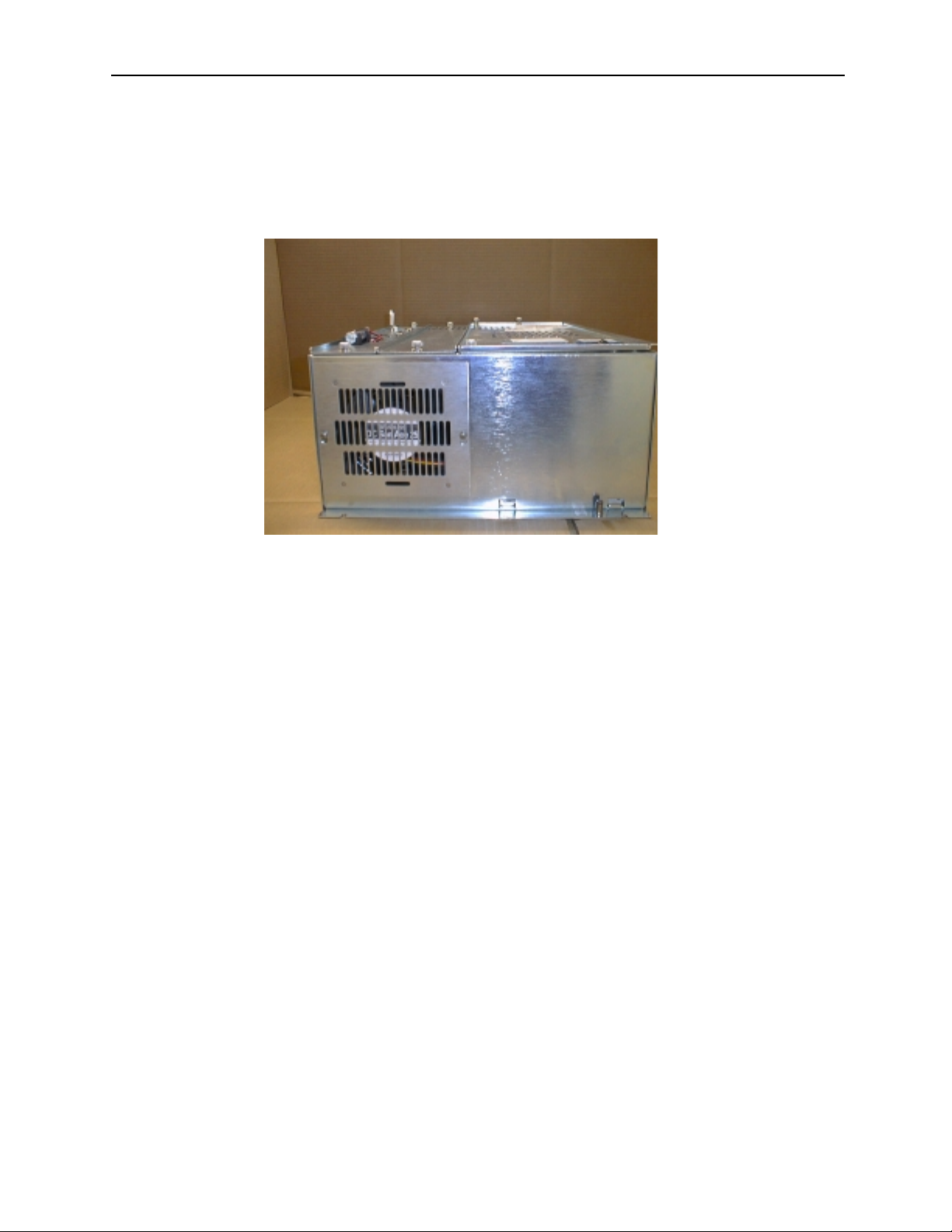
Verify the CPU rack cooling fan is running by placing a hand on the outside case in
the path of the airflow.
Figure 2.3: CPU Rack and Fan
If the cooling fan speed falls below 2000rpm, a “Slow Fan” warning message
appears. When this occurs, open the CPU rack and check the fan for any obstacles
that may inhibit the fan rotation. If no obstacles are present, call a Yaskawa customer service representative.
If the CPU rack cooling fan speed falls below 1800rpm, a “Fan Alarm of CNC
Unit” message appears. When this occurs, Cycle Start is not possible. Open the
CPU rack and check the fan for any obstacles that may inhibit the fan rotation. If
no obstacles are present, call a Yaskawa customer service representative.
2-4
Page 18

Chapter 2: Routine Inspection PC NC Maintenance Manual
2.5 Touch Screen
Clean the touch screen daily. Select PC Settings from the Utilities Menu. Select
the Touch Screen Cleaning button. When the screen below appears, proceed to
clean the touch screen.
1. Ensure there are no metal or other hard particles on the touch screen that may
scratch the screen.
2. Use a general purpose liquid glass cleaner and a clean rag.
3. Never spray glass cleaner directly onto the touch screen. Always spray onto
the clean rag.
4. Wipe the touch screen completely.
5. When finished, press the Escape key.
2-5
Page 19

PC NC Maintenance Manual Chapter 2: Routine Inspection
2.6 Control Panel
Details of the standard cabinet are explained below. Questions on customized cabinets should be referred to the manual issued by the machine manufacturer.
Follow the steps below for routine daily maintenance of the control panel.
1. Inspect the door(s) daily to ensure tight closure. The control panel is constructed as a dust-proof, sheet-steel enclosure with gasketed doors to keep out
dust and oil mists. Keep the door(s) tightly closed at all times.
2. Following inspection of the control with the door open, close the door and fasten the door locks (two per door) securely using the key provided (Number
YE001). When opening (counter-clockwise rotation) or closing (clockwise
rotation), insert the key all the way into the keyhole and turn until it clicks
(approximately a quarter-turn). The key can be removed from an open or
closed position.
Left-hand Hinge Door Right-hand Hinged Door
closed position
Note: If the optional door interlocking switch is provided, opening the door shuts
The following monthly maintenance must be performed.
1. Inspect the gaskets on the rims of the front and rear doors for openings or damage.
2. Inspect the inside of the enclosure; clean it if necessary.
open position
closed position
open position
Figure 2.4: Open and Closed Positions
off the main power supply and stops all operations.
3. Look for any opening in the door base when the doors are tightly shut.
2-6
Page 20

Chapter 3: Maintenance Instruments PC NC Maintenance Manual
Chapter 3: Maintenance Instruments
Measuring instruments, tools, and replacement parts are described in this chapter.
Table 3.1: Measuring Instruments
Name
Tester
or multi-purpose digital meter
Allowable Measuring
10 to 33VAC (at 40 to 100Hz)
Tolerance: ±2%
Several mV to 100VDC
Tolerance: ±2%
Up to multiples of 10MΩ To measure currents
The only required tools are those listed below.
• Phillips screwdrivers (large, medium, and small)
Range
Purpose
To measure AC power voltages
To measure DC power voltages
• Standard screwdrivers (medium and small)
• ROM extractor: IC extractor model GX-6
3-1
Page 21

PC NC Maintenance Manual Chapter 3: Maintenance Instruments
Maintenance/replacement parts are:
• Fuse model HMO3, 0.3A; approximate mass: 0.4g
• NC card fuse
• CPU rack fuse: 1A 250V 3AG fast-acting type glass body cartridge fuse; or
250V 3AG fast-acting type glass body cartridge fuse
Note: The current CPU rack fuse is 1A Littlefuse #312001, but will change to
3A Littlefuse #312003 fuse per ECO #N-9910-020.
• Motherboard battery: coin-type 3V lithium battery,
part # Mitsubishi #CR2032, or Maxell #CR2032
3-2
Page 22

Chapter 4: Troubleshooting PC NC Maintenance Manual
Chapter 4: Troubleshooting
4.1 Maintenance Data
To locate the cause of problems or when contacting your Yaskawa customer service representative for advice, users must precisely understand the actual situation.
To minimize the downtime, check the following points carefully.
CAUTION
• When an alarm occurs, eliminate the fault and assure operation safety before resetting it. Failure to
observe this caution could result in equipment malfunction.
• For details on the machine-related sequence, refer to the machine tool manual.
Checking the Status of Problems
(1) Understanding the Situation
To identify the nature of the problem, first check the following items.
• Type of operation that causes a problem.
Do other types of operations not cause problems?
• Q Details of problems
How, frequency (always or sometimes), and when?
• Unusual situation when the problem occurred.
• Was there an unusual external occurrence (such as power failure or
lightning) when the problem occurred?
• Timing of problem occurrence.
Did the problem occur during or after the operation of the keys, or in
a specific operation mode?
(2) Check Items
(a) Problems related with axis feed and spindle drive
Check the following items.
• Indication status of the LEDs on the drive unit
• Fuses and breakers
4-1
Page 23

PC NC Maintenance Manual Chapter 4: Troubleshooting
• Timing of problem occurrence – when the power is turned ON, during acceleration, during deceleration or during fixed speed spindle
rotation, etc.?
(b) Problems related to part program
Record the program block data, offset data, workpiece coordinate system offset data, coordinate system setting data, etc.
Checking the NC Information
Aside from the specific problem, the following information must be
obtained regarding the hardware environment.
• Machine tool builder’s name
• Delivery date of machine tool
• Type and model name of the machine tool
• Type and model name of the NC and units
Example
NC unit YASNAC PC NC
Servo drive SGDC-AJA
Servo motor SGMG
Spindle drive CIMR-M5N20155
Spindle motor UAASKD-11HB11
Display of Alarm Information
If an alarm occurs, the top priority alarm number and alarm comment are
displayed in the normal display area disregarding the selected mode and
the screen.
4-2
Page 24

Chapter 4: Troubleshooting PC NC Maintenance Manual
Cause of Alarm and Corrective Action
The following shows the listing of YASNAC PC NC alarms.
Table 4.1: Alarm Numbers and Classification
Number Contents Stop Mode Output How To Reset
0000 to
0049
0050 to
0099
0100 to
0499
1000 to
1099
2000 to
2199
3000 to
3299
8000 to
8049
9000 to
9049
No number
indication
BAT
indication
BAT, AXIS
No number
indication
Warning
message
Errors related to edit and operation
Occurring in the background mode
also.
Errors related to edit and operation
Not occurring in the background
mode.
Program error Block stop Input error
Program error
DNC, COMS total, etc.
Machine related error
OT, reference point return, machine
ready, in-position, etc.
Servo and spindle related alarm
ESP, CPU mutual monitoring
Memory check error
Watchdog timer error
Offline error
Error occurring in background editing (basically the same as with 0000
to 0049)
Battery error
Encoder alarm
Key operation error, edit operation
error (not serious operation error)
Block stop Input error
alarm
Block stop Input error
alarm
alarm
Block stop Input error
alarm
Stop after
deceleration,
or immediate
stop
Immediate
stop, or se rve,
OFF
Immediate
stop, or serve
OFF
Not stopped Back-
Not stopped No output Changing the battery
Not stopped Warning Next key operation
Alarm Reset operation after removing the
Alarm Reset after removing the cause.
Alarm For maintenance
ground
error
output
Reset
Reset
Power OFF for #0050 and #0051
Reset
Reset
cause. With the alarm caused by
the machine ready signal, if it
occurs in the first power ON operation, it is automatically reset.
With the SVOFF alarm, it is automatically reset by the SVON.
CPU halt
Switching to the maintenance
screen
Reset or with reset soft-key
4-3
Page 25

PC NC Maintenance Manual Chapter 4: Troubleshooting
Troubleshooting (1)
(1) Alarm Number 1099 (High Temperature)
Table 4.2: Countermeasures - Alarm #1099 (High Temperature)
Cause Check Item Countermeasures
Ambient temperature of the
NC rack exceeded the
specified value* due to the
failure of the cooling fan.
* 70ºC ± 3ºC when mea-
sured above CPS-18.
Internal temperature of the
power supply unit is high.
Ambient temperature of the
l NC unit is high.*
*: Allowable temperature
range for operation is
0 to 40ºC.
Open the NC unit door to check
whether the cooling fan is operating
correctly.
• Ensure that air is blowing out
through the ventilation port of
the cooling duct.
• Ensure that the ventilation port
of the cooling duct is not
blocked.
Allow the power supply unit to cool
by turning OFF the power with the
PC NC unit door opened. If the
alarm occurs even after the power
supply unit has been cooled for 30
minutes, the power supply unit is
faulty.
Measure the ambient temperature.
• If the NC unit is placed in direct
sunlight, the NC unit temperature may exceed the allowable
limit.
If the fan is faulty, it must be
replaced. Contact your Yaskawa
customer service representative.
If the cooling duct is blocked,
remove the interfering object and
start the cooling fan.
The power supply unit must be
changed. Contact your Yaskawa
customer service representative.
This is not the failure of the NC
unit. Remove the cause.
4-4
Page 26

Chapter 4: Troubleshooting PC NC Maintenance Manual
(2) Alarm Numbers 2061 to 2068 (Reference Point Return Area
Error)
Table 4.3: Troubleshooting - Alarm #2061 ~ 2068 (Reference Point Return Area Error)
Cause Check Item Countermeasures
The reference
point return start
point is at the
zero point side
of the deceleration limit switch.
Approach
feedrate is too
fast.
Deceleration limit switch (DECLS)
#3073 DO (1st axis)
#3073 D1 (2nd. ax is)
#3073 D2 (3rd axis)
#3073 D3 (4th axis)
#3073 D4 (5th axis)
If reference point return is started from a point
located at the reference point side of DECL (point
C) as shown below, an alarm occurs.
Note: This error check is not made before the
execution of manual reference point
return after the power is turned ON.
Compare the setting for the approach feedrate
parameter with the parameter list.
Execute reference
point return again
while observing the
I/O signal monitor
screen
Return the axis to a position on
the deceleration LS or away
from it and, then execute reference point return once again.
Change the setting for parameters pm2521 to pm2525 to an
appropriate value.
Table 4.4: Troubleshooting - Alarm Numbers 2071 ~ 2078, 2081 ~ 2088
Cause Check Item Countermeasures
Alarm in manual reference
point return operation
Alarm in automatic reference
point return operation
(3) Alarm Numbers 2071 to 2078, 2081 to 2088 (Reference Point
Return Position Error)
(Reference Point Return Position Error)
Determine w h e the r th e er r or occurs every
time.
G28: Determine whether the alarm
occurs every time.
G27: Check the point specified in the
program to determine whether it
agrees with the zero point.
4-5
Contact a Y askawa customer
service representative.
Contact a Y askawa customer
service representative.
Review the program.
Page 27

PC NC Maintenance Manual Chapter 4: Troubleshooting
(4) Alarm Numbers 2101 to 2108 (P-SET Error)
The P-SET alarm occurs if the error between the position specified in the program and the actual machine position is lar ger than
the value set for parameterspm1321 (1st axis) to pm 1325 (5th
axis) in the following modes of operation.
At the completion of positioning in G00, G27, G28, G29, G30,
etc., error detect ON (1/O monitor parameter #3004 D4 = 1), and
G04 (dwell).
If error pulses have been accumulated, check the number of accumulated pulses on the Error Pulse Display Screen before contacting a Yaskawa customer service representative.
(5) Alarm Number 3000 (Servo Power Not Ready)
Table 4.5 Troubleshooting - Alarm #3000 (Servo Power Not Ready)
Cause Check Item Countermeasures
Secondary power supply is not
applied
With the secondary power ON,
I/O input specification is not
turned ON (for automatic servo
power ON)
Emergency stop signal stays
ON.
The secondary power ON signal is turned OFF due to some
other alarm.
If the NC RESET switch is depressed
after depressing the POWER ON button once, or after clearing the emergency stop or alarm state, the alarm
message is displayed. This does not
indicate the occurrence of an alarm.
Verify the following on the I/O monitor
screen:
#3005 DO = 1 (SVON)
#3503 DO = 1 (SVONS)
Determine whether alarm Number
3002 is displayed (#3503 D4 = 1) on
the screen.
Check the alarm indication for other
alarms.
Press the POWER ON button again.
Contact your Yaskawa
customer service
representative.
Reset the emergency stop
input signal.
Take appropriate measures by referring to the
alarm code.
4-6
Page 28

Chapter 4: Troubleshooting PC NC Maintenance Manual
(6) Alarm Number 3001 (Control Not Ready)
The PC NC executes self-diagnosis after power ON. This alarm
occurs when the positioning error checked during this self-diagnosis exceeds the values set for parameters pm 1321 (1st axis) to
pm1325 (5th axis).
Table 4.6: Troubleshooting - Alarm Number 3001 (Control Not Ready)
Cause Check Item Countermeasures
Machine axes have moved. Select the error pulse display screen
from the present position display
PG signal remains output. PG or AC servo must be
screen in the common process and
check the error pulse value.
Contact a Yaskawa customer
service representative.
changed. Contact a Yaskawa
customer service representative.
(7) Alarm Numbers 3041 to 3048 (Excessive Follow-up Error)
If the follow-up error between the co mmand values and the ac tual
position values exceeds 120% of the error in rapid traverse
(100%) operation, this alarm occurs. Check the values set for
parameters pm1671 to pm1675, pm1681 to pm1685 and contact a
Yaskawa customer service representative.
(8) Alarm Number 3051 (Excessive Follow-up Error: Spindle)
If the follow-up error between the co mmand values and the ac tual
position values exceeds the value set for parameter pm1351, this
alarm occurs. Check the values set for parameter pm1351 and
contact a Yaskawa customer service representative.
(9) Alarm Numbers 3061 to 3068 (Overload)
Table 4.7: Troubleshooting - Alarm Numbers 3061 ~ 3068 (Overload)
Cause Check Item Countermeasures
Cutting conditions Determine whether the alarm occurred during
machining.
Guideways are not lubricated properly, causing
heavy axis movements.
Inspect the guideways to determine whether
they are lubricated properly.
4-7
Turn OFF the power and
allow the servomotor to cool.
Then change to lighter
machining conditions and
restart the operation.
Contact the mac hine
tool builder, or a Yaskawa
customer service representative.
Page 29

PC NC Maintenance Manual Chapter 4: Troubleshooting
(10) Alarm Numbers 3081 to 3088 (Broken PG Cable)
The A and B phase signal cables are checked for breakage.
Table 4.8: Troubleshooting - Alarm Numbers 3081 ~ 3088 (Broken PG Cable)
Cause Check Item Countermeasures
Signal cables between the
NC and the AC servo drive
unit are broken or loose.
Faulty PG cable breakage
detection circuit.
Error in motor type parameter setting
Ensure that the cable connectors are
plugged into the connectors securely.
Determine whether the alarm occurs in
the first pressing of the POWER ON
button even when the cables are connected c orrectly.
Determine whether the motor type setting parameters (pm 1061 to pm 1065)
has been set to “0”.
If they are loose or disconnected,
re-connect them correctly.
Contact your Yaskawa
customer service representative.
Correct the setting for the motor
type parameters (pm1061 to
pm1065).
(11) Alarm Number 3091 (Broken Spindle PG Cable)
The A, B, and C phase signal cables are checked for breakage.
Table 4.9: Troubleshooting - Alarm Number 3091 (Broken Spindle PG Cable)
Cause Check Item Countermeasures
Signal cables between the
NC and the AC servo drive
unit are broken or loose.
Faulty PG cable breakage
-detection circuit
Faulty PG If an alarm occurs during low speed
Ensure that the cable connectors are
plugged into the connectors securely.
Determine w hether the alarm oc curs in
the first pressing of POWER ON button
even when the cables are connected
correctly.
operation, the PG may be faulty.
If they are loose or disconnected, re-connect them correctly.
Contact a Yaskawa customer
service representativ e.
Contact a Yaskawa customer
service representativ e.
(12) Alarm Numbers 3121 to 3125 (Excessive Speed)
This alarm is detected if the motor speed exceeds 1.2 times the
maximum motor speed.
Contact a Yaskawa customer service representative.
(13) Alarm Numbers 3161 to 3165 (Absolute Error)
Malfunction of the absolute encoder is detected. Contact a
Yaskawa customer service representative after checking the following:
4-8
Page 30

Chapter 4: Troubleshooting PC NC Maintenance Manual
• Whether the alarm occurs immediately after the control
power is turned ON.
• Whether the alarm is cleared when the power is turned
OFF and then turned ON again.
• Whether the battery alarm occurs at the same time.
(14) Alarm Numbers 3181 to 3185 (Position Error)
Malfunction of the PG pulse (counter in the absolute encoder) is
detected. Contact your Yaskawa customer service representative
after checking the following:
• Whether the alarm occurs immediately after the control
power is turned ON.
• Whether the alarm occurs frequently during operation.
(15) Alarm Numbers 3201 to 3205 (Servo Drive Unit Communication
Error)
Communication error between the NC and the AC servo drive
unit is detected. Contact your Yaskawa representative.
(16) Alarm Numbers 3301 to 3305 (Overcurrent)
Contact your Yaskawa customer service representative after
checking the following:
• Whether the alarm occurs immediately after the control
power is turned ON.
• Whether the alarm occurs after turning ON the main
power.
(17) Alarm Number 3311 to 3315 (MCCB Trip)
• Contact your Yaskawa customer service representative
after checking the following:
• Whether the alarm occurs immediately after the control
power is turned ON.
• Whether the alarm occurs after turning ON the main
power.
4-9
Page 31

PC NC Maintenance Manual Chapter 4: Troubleshooting
(18) Alarm Number 3321 to 3325 (Regeneration Error)
Contact your Yaskawa customer service representative after
checking the following:
• Whether the alarm occurs immediately after the control
power is turned ON.
• Whether the alarm occurs after turning ON the main
power.
(19) Alarm Numbers 3331 to 3335 (Over Voltage)
Contact your Yaskawa customer service representative after
checking the following:
• Whether the alarm occurs at the start of motor rotation.
• Whether the alarm occurs during deceleration.
(20) Alarm No.: 3341 to 3345 (Under Voltage)
Contact your Yaskawa customer service representative after
checking the following:
• Whether the alarm occurs after turning ON the main
power.
(21) Alarm Numbers 3351 to 3355 (Heat Sink Overheat)
Table 4.10: Troubleshooting - Alarm # 3351 ~ 3355 (Heat Sink Overheat)
Cause Check Item Countermeasures
Faulty control board Check whether the alarm occurs imme-
diately after the control power is turned
ON.
Fan stop Check whether the alarm occurs during
operation (alarm recurs if the control
power is turned ON after turning it OFF
once, or the operation restarts when the
NC is reset after several minutes.)
Check whether the fan is rotating.
Contact your Yaskawa
representative.
Contact your Yaskawa
customer service representative.
4-10
Page 32

Chapter 4: Troubleshooting PC NC Maintenance Manual
(22) Alarm Numbers 3361 to 3365 (Wire Break in Current Instruction
Cable)
Contact your Yaskawa customer service representative after checking
the following:
• Whether the alarm occurs immediately after the control
power is turned ON.
• Whether an alarm other than the current instruction cable
breakage alarm occurs.
(23) Alarm Numbers 3371 to 3375 (Open Phase Detection)
Contact your Yaskawa customer service representative after
checking the following:
• Whether the alarm occurs immediately after the control
power is turned ON.
• Whether the alarm occurs after turning ON the main
power.
Troubleshooting (2)
Check both the drive unit and the PC NC unit for systems equipped with a
drive unit compatible with YENET1 200. If a fault is detected, the drive
unit notifies the PC NC unit of the alarm information in both systems.
The drive unit first gives the PC NC unit the information on the occurrence
of an alarm (Alarm Number 3101 to 3105 and Number 3201) and then the
content of the alarm. The NC unit displays alarm Number 3100 when it
receives the alarm information from the drive units.
Therefore, three alarms usually occur if an error is detected in the drive
unit. If a blown fuse occurs with the X-axis servo unit, Alarm Numbers
3100, 3101, and 3021 occur.
(1) Alarm Numbers 3021 to 3025 (Fuse Blown)
The main circuit of the servo unit may be faulty.
The servo unit detects the error.
Contact your Yaskawa customer service representative.
4-11
Page 33

PC NC Maintenance Manual Chapter 4: Troubleshooting
(2) Alarm Numbers 3041 to 3045, 3051 (Excessive Follow-up Error)
This alarm occurs if the follow-up error exceeds 120% of the
error in rapid traverse (100%) operation.
The servo unit detects the alarm.
Improper gain adjustment is one of the reasons.
Contact a Yaskawa customer service representative.
(3) Alarm Numbers 3061 to 3065 (Overload)
This alarm occurs if the load exceeds the rated torque considerably.
The servo unit detects the error.
Review the cutting conditions. Contact a Yaskawa customer service representative after checking whether the alarm occurred
simply after turning the control power ON.
(4) Alarm Nos.: 3081 to 3085 and 3091 (Broken PG Cable)
The encoder signal cable or the encoder itself will be faulty.
The servo unit or the inverter detects the error.
Contact a Yaskawa customer service representative.
(5) Alarm Numbers 3101 to 31051 (Servo Alarm)
This alarm occurs when the NC unit detects the alarm signal output from the servo unit.
Check the contents of the alarm by displaying the servo alarm display screen (press [F2] of the alarm job in the common process.).
4-12
Page 34

Chapter 4: Troubleshooting PC NC Maintenance Manual
(6) Alarm Numbers 3111 to3115 (Servo Communication Alarm)
Probable causes of this alarm are a broken YENET1 200 communication cable, loose cable connection and communication processing error.
The servo unit detects the alarm.
Contact a Yaskawa customer service representative after making
sure that the cable is securely connected.
(7) Alarm Numbers 3121 to 3125 (Excessive Speed)
This alarm occurs if the motor speed exceeds 4950 r/rein or the
value set for the parameter.
The servo unit detects the alarm.
Check whether the connection to the encoder is correct.
Contact a Yaskawa customer service representative.
(8) Alarm Numbers 3141 to 3145 (Overrun, Run-away Prevention)
The encoder will be faulty.
The servo unit detects the alarm.
Contact a Yaskawa customer service representative.
(9) Alarm Numbers 3151 to 3155 (Phase Detection Error)
The encoder signal cable or the encoder itself will be faulty.
The servo unit detects the error.
Contact a Yaskawa customer service representative.
(10) Alarm Numbers 3161 to3165 (Absolute Error)
This alarm occurs if the absolute value data cannot be received
correctly in one to two seconds after turning ON the power to the
encoder.
The servo unit detects the error.
4-13
Page 35

PC NC Maintenance Manual Chapter 4: Troubleshooting
The encoder or the servo unit will be faulty.
Contact a Yaskawa customer service representative.
(11) Alarm Numbers 3181 to 3185 (Absolute Position Error)
The number of feedback pulses is checked every turn of the
encoder, and this alarm occurs if there is an error in the number of
pulses counted.
The servo unit detects the alarm.
The encoder or the servo unit will be fa ulty, or malfunction could
have occurred due to noises.
Contact a Yaskawa customer service representative.
(12) Alarm Number 3201 (Inverter Alarm)
This alarm occurs when the NC unit detects the alarm signal output from the inverter.
Check the contents of the alarm by displaying the servo alarm display screen (press [F2] of the alarm job in the common process.).
(13) Alarm Numbers 3281 to 3285, 3291 (YENET1 200 command
time-out)
This alarm occurs when the YENET1200 communication lines
fail to get ready.
The NC units detects the alarm.
The servo unit or the inverter unit is faulty.
Contact a Yaskawa customer service representative.
(14) Alarm Numbers 3301 to 3305 (Overcurrent)
The servo unit detects the alarm.
The servo unit may be faulty if the alarm occurs before the operation is started after turning the power ON.
If the alarm occurs during operation, a ground fault of the motor
is the cause.
4-14
Page 36

Chapter 4: Troubleshooting PC NC Maintenance Manual
Contact a Yaskawa customer service representative.
(15) Alarm Numbers 3331 to 3335 (Over Voltage)
The servo unit detects the alarm.
If the alarm occurs when the power is turned ON to the spindle,
the input voltage may be too high.
If the alarm occurs during motor operation, the operation conditions (i.e., lower motor speed) must be reviewed.
If the alarm occurs when the servo control power is turned ON,
the servo unit will be faulty.
Contact a Yaskawa customer service representative.
(16) Alarm Numbers 3351 to 3355 (Heat Sink Overheat)
This alarm occurs when the heat sink temperature is abnormally
high.
The servo unit detects the alarm.
If this alarm occurs, turn OFF the power and allow the heat sink
to cool. After that, turn the power ON again.
If the alarm occurs immediately after turning the power ON, the
servo unit is faulty.
Contact a Yaskawa customer service representative.
(17) Alarm Numbers 3381 to 3385, 3391 (YENET1200 Communica-
tion Error)
This is an communication error between the NC unit and the
servo unit or between the NC unit and the inverter unit; the NC
unit detects the alarm when no answer is returned for the command output by the NC unit.
The servo unit or the inverter unit may be faulty, or the cable may
not be connected securely.
Contact a Yaskawa customer service representative.
4-15
Page 37

PC NC Maintenance Manual Chapter 4: Troubleshooting
(18) Alarm Numbers 3401 to 3405 (Converter Alarm)
This alarm occurs due to the following reasons: blown fuse,
regeneration alarm, open phase, or faulty board.
The servo unit detects the alarm.
Contact a Yaskawa customer service representative.
(19) Alarm Numbers 3411 to 3415 (Servo Unit Alarm)
This alarm occurs due to the following: destroyed parameter setting, faulty current detector, encoder battery alarm, memory error
or sensor error.
The servo unit detects the alarm.
The servo unit or the motor is faulty.
Contact a Yaskawa customer service representative.
(20) Alarm Number 3421 (Inverter Unit Alarm)
This alarm occurs when the inverter detects an alarm other than
the converter alarm, broken PG cable, excessive follow-up error
and communication error.
Contact a Yaskawa customer service representative.
(21) Alarm Numbers 3425, 3431 to 3435 (YENET1 200 Watchdog
Error)
This alarm occurs when the NC unit detects the watchdog error
with the inverter unit or the servo unit.
The inverter unit or the servo unit will be faulty.
Contact a Yaskawa customer service representative.
(22) Alarm Numbers 3441 to 3445 (Ground Fault)
This alarm occurs when the servo unit detects the alarm when the
power is turned ON.
The motor insulation is faulty.
4-16
Page 38

Chapter 4: Troubleshooting PC NC Maintenance Manual
Contact a Yaskawa customer service representative.
(23) Alarm Number 3451 and 3452 (Follow-up Error)
This alarm occurs when the follow-up error exceeds the value set
for the servo unit parameter.
The servo unit detects the alarm.
If this alarm occurs during axis feed over a long distance, either
the command speed must be lowered or the gain must be
increased.
If the motor does not rotate, the servo unit may be faulty.
Contact a Yaskawa customer service representative.
Alarms Not Indicated by Alarm Numbers
(1) No Display is Given on the CRT
If nothing is displayed on the CRT, the CRT itself may be faulty,
or the display circuit or connection cables may be faulty. When
nothing is displayed even if the PC NC power can be turned ON,
check the cable connection to the operation panel and also the
connectors.
(2) Handle Mode Operation is Impossible
(a) Handle mode signal is not input
• Verify the bit status of UO monitor #3000.
D2 = 1
Other bits (DO, D1, D3 to D7) = 0
• Verify the mode display given in the normal display area
on the screen.
4-17
Page 39

PC NC Maintenance Manual Chapter 4: Troubleshooting
(b) Axis selection signal is not input
• I/O monitor
Verify whether one of the following bits is ON.
#3070
D
= l 1st axis
0
D
= l 2nd axis
l
= 1 3rd axis
D
2
= 1 4th axis
D
3
D
= 1 5th axis
4
• No. 2 handle
Verify whether one of the following bits is ON.
#3080
= l 1st axis
D
0
= l 2nd axis
D
l
D
= 1 3rd axis
2
= 1 4th axis
D
3
D
= 1 5th axis
4
• No. 3 handle
Verify whether one of the following bits is ON.
#3081
= l 1st axis
D
0
= l 2nd axis
D
l
D
= 1 3rd axis
2
= 1 4th axis
D
3
D
= 1 5th axis
4
4-18
Page 40

Chapter 4: Troubleshooting PC NC Maintenance Manual
(c) There is no input to handle PG
• Check the input voltage (5V) at the handle PG terminal.
• Check the handle PG signal cable connector to see if it is
securely plugged in.
(d) Handle PG is faulty
Verify the following (counter monitor) on the I/O screen if the
values change according to the operation of the pulse handle.
#3037 (No. 1 handle)
#3038 (No. 2 handle)
#3039 (No. 3 handle)
(e) Other related parameters
Verify the setting for the following parameters.
Maximum feedrate for handle operation Parameter pm2860 (linear axis) Parame-
ter pm2861 (rotary axis)
Acceleration/deceleration time constant Parameters pm2561 to pm2565
Pulse multiplication ratio of “×100” is set (pm2003
D7 = 1)
Parameter pm2549
(3) Jog Operation is Impossible
(a) Jog mode signal is not input
Verify the bit status of I/O monitor #3000.
Dl = l
Other bits (DO, D2 to D7) = O
4-19
Page 41

PC NC Maintenance Manual Chapter 4: Troubleshooting
(b) Axis move direction signal is not input.
Verify the bit status of I/O monitor #3071 and #3072.
#3071 #3072
D0 +1st axis D0 -1st axis
Dl +2nd axis Dl -2nd axis
D2 +3rd axis D2 -3rd axis
D3 +4th axis D3 -4th axis
D4 +5th axis D4 -5th axis
(c) Jog feedrate signal is not input, or job feedrate setting param-
eter is incorrect
Verify the bit status on the I/O monitor screen to determine
whether it changes according to the operation of the JOG
FEEDF.ATE switch, and also verify whether the setting for
the parameters is correct.
4-20
Page 42

Chapter 4: Troubleshooting PC NC Maintenance Manual
Table 4.11: Jog Feedrate
I/O MONITOR #3002
STEP
JV16 JV8 JV4 JV2 JV 1
1 00000Set for parameter pm2400
2 00001Set for parameter pm2401
3 00010Set for parameter pm2402
4 00011Set for parameter pm2403
5 00100Set for parameter pm2404
6 00101Set for parameter pm2405
7 00110Set for parameter pm2406
8 00111Set for parameter pm2407
9 01000Set for parameter pm2408
1001001Set for parameter pm2409
1101010Set for parameter pm2410
1201011Set for parameter pm2411
1301100Set for parameter pm2412
1401101Set for parameter pm2413
1501110Set for parameter pm2414
1601111Set for parameter pm2415
1710000Set for parameter pm2416
1810001Set for parameter pm2417
1910010Set for parameter pm2418
2010011Set for parameter pm2419
2110100Set for parameter pm2420
2210101Set for parameter pm2421
2310110Set for parameter pm2402
2410111Set for parameter pm2423
2511000Set for parameter pm2424
2611001Set for parameter pm2425
2711010Set for parameter pm2426
2811011Set for parameter pm2427
2911100Set for parameter pm2428
3011101Set for parameter pm2429
3111110Set for parameter pm2430
3211111Set for parameter pm2431
JOG FEEDRATED4 D3 D2 D1 D0
4-21
Page 43

PC NC Maintenance Manual Chapter 4: Troubleshooting
(d) Axis interlock is input
Check the bit status on the I/O monitor screen. If “0”, the corresponding axis cannot move.
#3078
D
= l 1st axis
0
D
= l 2nd axis
l
= 1 3rd axis
D
2
= 1 4th axis
D
3
D
= 1 5th axis
4
(e) Machine lock is ON
• Even when the machine lock function is ON, the position
display changes. Check the input of the machine lock
switch (1/O monitor, #3006 D5 = 0). If “1”, the axes
do not move.
• Check the internal toggle switch (parameter pm0000 D 1
= 0). If “1”, the axes do not move.
(4) Manual Rapid Traverse is Impossible
(a) The rapid mode is not selected
Check the bit status of I/O monitor #3000.
DO = l
Other bits (D1 to D7) = 0
(b) Axis move direction signal is not input.
Check the bit status of I/O monitor #3071 and #3072.
#3071 #3072
D0 +1st axis D0 -1st axis
Dl +2nd axis Dl -2nd axis
D2 +3rd axis D2 -3rd axis
D3 +4th axis D3 -4th axis
D4 +5th axis D4 -5th axis
4-22
Page 44

Chapter 4: Troubleshooting PC NC Maintenance Manual
(c) Rapid traverse override is not input
• Check the bit status on the I/O monitor screen to determine whether it changes according to the operation of the
RAPID TRAVERSE RATE OVERRIDE switch, and also
verify whether the setting for the parameters is correct.
Table 4.12: Input Status and Rapid Traverse Rate
Input Status Of #3003 Rapid Traverse Rate
ROV2 ROV1 1st axis 2nd axis 3rd axis 4th axis 5th axis
11Set for
pm2801
1 0 [Set for
pm2801] × 1/
2
0 1 [Set for
pm2801]
× 1/4
00F
(set for pm2447)
0
Set for
pm2802
[Set for
pm2802] × 1/
2
[Set for
pm2802]
× 1/4
Set for
pm2803
[Set for
pm2803] × 1/
2
[Set for
pm2803]
× 1/4
Set for
pm2804
[Set for
pm2804] × 1/
2
[Set for
pm2804]
× 1/4
Set for
pm2805
[Set for
pm2805] × 1/
2
[Set for
pm2805]
× 1/4
Table 4.13: Input Status and Rapid Traverse Rate
Input Status Rapid Traverse Rate
ROV4 ROV2 ROV1 1st to 5th Axis I
101F
100F
0 1 1 100%
01050%
00123%
000F
(set for prn2449)
2
(set for pm2448)
1
(set for pm2447)
0
(d) Parameter related to Rapid traverse is set incorrectly.
4-23
Page 45

PC NC Maintenance Manual Chapter 4: Troubleshooting
(e) Axis interlock is input
Check the bit status on the I/O monitor screen. If “O”, the
corresponding axis cannot move.
#3078
D
= l 1st axis
0
= l 2nd axis
D
l
D
= 1 3rd axis
2
= 1 4th axis
D
3
= 1 5th axis
D
4
(f) Machine lock is ON
• Even when the machine lock function is ON, position display changes. Check the inpu t of the mac hine lock switc h
(I/O monitor, 3006 D5 = 0). If “1”, the axes do not move.
• Check the internal toggle switch (parameter pm0000 D1 =
0). If “1”, the axes do not move.
(5) Manual Reference Point Return is Incorrect
The following explanation is given assuming that jog and rapid
traverse are executed correctly.
(a) Manual reference point return signal is not input
Check the I/O monitor #3007 D0. The status must be” 1”.
Otherwise, the axis continues moving to OT at the same feedrate even if it reaches point A.
(b) Jog or rapid traverse mode is not selected.
I/O monitor #3000 D0 or D1 must be”1”.
(c) Deceleration limit switch signal is not input.
Check I/O monitor #3073 DO to D4 while moving an axis at a
slow feedrate such as in jog operation.
4-24
Page 46

Chapter 4: Troubleshooting PC NC Maintenance Manual
Deceleration switch signal
(*DCX signal)
Figure 4.1: Reference Point Return Control I/O Signals
(d) Parameter setting is incorrect.
Check the setting for the related parameters against the
parameter sheet.
(e) Position of the dog for the deceleration limit switch is incor-
rect. If the dog position is incorrect, the zero point could be
shifted by one turn of the motor.
(f) Others (loose coupling or dog)
If another adjustment is incorrect, zero point could shift at
random.
(6) Cycle Start is Impossible
(a) Cycle start signal is not input or feed hold signal is open.
Determine whether the I/O monitor #3003 D0 is “1” when the
cycle start switch is pressed. In this case, the feed hold signal
must be open; this can be confirmed by I/O monitor #3003
D1 = 1.
(b) Start interlock signal is input.
If I/O monitor #3004 D2 = 1, cycle start is impossible.
(c) The NC is in the reset status.
Normal status: I/O monitor #3500 D1 = 0.
Also check the external reset signal status.
Normal status: I/O monitor #3004 D1 = 0
4-25
Page 47

PC NC Maintenance Manual Chapter 4: Troubleshooting
(7) G01, G02, or G03 Mode Operation is Impossible
(a) The spindle is in the speed agreed status.
Verify whether parameter pm 1000 D7 = 1.
If it is “1”, check whether the spindle is in the speed agreed
status by I/O monitor #3111.
(b) FEEDRATE OVERRIDE switch setting is 0%.
Determine whether the setting for I/O monitor #311 1 D0 to
D4 is correct.
(c) ln the dry run mode, setting for jog feedrate is incorrect.
Table 4.14: I/O Monitor and Feedrate Override
I/o Monitor #3040
D4 D3 D2 D1 D0
OV16 OV8 OV4 OV2 OV 1
Feedrate Override
(Automatic Operation)
000000%
0000110%
0001020%
0001130%
0010040%
0010150%
0011060%
0011170%
0100080%
0100190%
01010100%
01011110%
01100120%
01101130%
01110140%
01111150%
10000160%
10001170%
10010180%
10011190%
10100200%
10101220%
10110240%
10111260%
4-26
Page 48

Chapter 4: Troubleshooting PC NC Maintenance Manual
Table 4.14: I/O Monitor and Feedrate Override (Continued)
11000280%
11001300%
11010340%
11011380%
11100420%
11101460%
11110500%
11111540%
(d) Start interlock signal is input.
If I/O monitor #3004 D2 = 1, start interlock is ON.
Normal: #3004 D2 = 0
(e) Axis interlock is input.
Verify I/O monitor #3087 D0 to D4.
Normal: #3078 D0 to D4 = 1
(f) Setting of the servo system is incorrect.
Verify whether the axes can be moved manually.
(8) Spindle Rotation is Impossible
(a) Error in a program (no S command or no spindle start M
code)
Verify the contents of the program on the [RUN] screen.
(b) Start signal has not been input.
Verify the output signals (#1100s) on the I/O monitor screen.
(c) Spindle rotation command has not been output.
Verify #3654 to #3656 on the 110 monitor screen.
(d) The spindle drive is in the alarm status.
Verify the alarm indication of the spindle drive.
(e) Combination of GRO and SOR is incorrect, or “0’ is input for
parameter pm1412 or pm1413.
4-27
Page 49

PC NC Maintenance Manual Chapter 4: Troubleshooting
Table 4.15: Input of GRO and SOR and S4-digit Command Analog Voltage
I/O Monitor #3110
S4-digit Command Analog VoltageD7 D6
GRO Input SOR Input
0 0 Voltage corresponding to the spindle speed
specified in the NC program.
0 1 Voltage corresponding to parameter pm 1412
1 0 Voltage corresponding to parameter pm 1413
110V
Note: If “1” is set for parameter pm1000 D5, SSTP input is reversed.
(f) Setting for the parameters related to spindle operation is
incorrect.
Verify the setting for the related parameters.
#3110 D0 GR1
#3110 D1 GR2
#3110 D2 GR3
#3110 D3 GR4
Figure 4.2: Spindle Rotation
4-28
Page 50

Chapter 4: Troubleshooting PC NC Maintenance Manual
(9) FIN Wait Status after Execution of Spindle Related Commands
If sequence processing is interrupted waiting for a signal, the NC
enters the FIN wait status.
(a) Spindle speed agree signal is not input.
If the NC enters this status after the execution of a command
such as “M03 S100”, verify whether #311 1 D6 = 1 (waiting
for FIN).
Verify the I/O signals of #1000s at the I/O section by referring
to the ladder chart supplied by the machine tool builder.
(b) Spindle zero speed signal is not input.
If the NC enters this status after the execution of the “M05”
command, check the I/O signals of #1000s at the I/O section
by referring to the ladder chart supplied by the machine tool
builder.
(c) Others
If the NC enters this status after the execution of “M19” or
“M20” (spindle orientation command), check the I/O signals
related with spindle orientation by referring to the ladder chart
supplied by the machine tool builder.
(10) Edit Operation is Impossible
(a) The edit lock signal is input.
Check I/O monitor #3007 D2.
Normal: #3007 D2 = 0
If “#3007 D2 = 1”, program edit is impossible.
(b) Edit lock is set by the parameter (pm0000 D7).
Set “pm0000 D7 = 0” to cancel the edit lock setting.
(c) Others
The corresponding alarm message is displayed.
OVER MEM CAP !
TOO MANY PROGS !
ALREADY IN !
Delete unnecessary programs and edit the program again.
4-29
Page 51

PC NC Maintenance Manual Chapter 4: Troubleshooting
(11) Skip Function (G31) Failure
The skip signal has not been input.
• Check the ON/OFF status of the skip signals.
• Check the operation of proximity switches.
PC NC Alarms Not Indicated By Alarm Numbers
(1) Fuse F1 blown on JZNC-JFC 10 card of CPU Rack.
When the 0.3 A F1 Fuse is blown on the JFC 10 card, the “3002
Emergency stop” Alarm occurs on the CNC.
In the diagnostic, when the # 3500 bit 2 * ESPS signal is ON, and
the “3002 Emergency stop” alarm still occurs on the PC NC Status bar, check the 0.3 A F1 Fuse on the JFC 10 card.
(2) Fuse F2 blown on JZNC-JFC 10 card of CPU Rack.
When the 5A F2 fuse is blown on the JFC 10 card, the “3001
Servo Alarm and 3002 Emergency stop” alarms occur. Check the
LED D4, just above CN04 Connector of the JFC 10 card of CPU
Rack. If this LED is not lit, the F2 Fuse has blown. Replace the
fuse.
(3) The Servo ON and Shut Down button connections are not con-
nected, or are wrongly connected.
When the Servo ON and Shut Down buttons are not connected to
the CN12 Connector, or are wrongly connected, “3002 Emergency stop and 3001 Servo alarms” is displayed on the PC NC.
Check that the Servo ON and Shut Down buttons are properly
connected to the CN12 Connector.
Note: When the F1 or F2 fuses are blown, replace them with
the same type of fuse.
Touch Screen Maintenance
The touch screen requires periodic cleaning as follows.
1. Whenever chips fall on the display unit.
2. Whenever coolant falls.
4-30
Page 52

Chapter 4: Troubleshooting PC NC Maintenance Manual
3. Whenever dust has accumulated on the screen.
4. Whenever greasy, or when any mist, or dust appears on the
screen.
5. If the display is not clear or clean.
Clean the touch screen as follows:
Go to Utilities, → PC Se ttings . Touch the Touch Screen Cleaning icon. A
blank screen display appears. A blank screen display appears, thereby
making any dust on the screen easy to view, and easy to clean.
Do:
1. Use standard glass cleaning liquid, applied to a clean cloth, to
wipe the touch screen.
2. Use only a clean, soft cloth.
Don’t:
1. Spray glass cleaning liquid directly on the touch screen. Apply
cleaning fluid only with clean cloth.
2. Use any hard or sharp materials to clean the touch screen.
3. Use a sponge or hands to clean the touch screen.
4. Apply pressure while cleaning the touch screen
PC NC Mode of Operation
The PC NC operation modes can be broadly divided into two categories:
the online mode and the offline mode. Although the operation mode can be
switched using the switch settings, it cannot be switched during operation.
(The PC NC references the system number switches only at system startup.)
** If the system is started after the system number switches are set into
undefined numbers, or the hardware check program has not been booted
and the system number switches are set as B &C, a “Boot Log” message
appears and the system will not start normally.
4-31
Page 53

PC NC Maintenance Manual Chapter 4: Troubleshooting
Table 4.16: Operation Mode Content
System Number
Switch
0 Normal operation mode O
1 Normal operation mode O
2 Normal operation mode O
4 Ladder development mode O
E Memory operation mode **
Online = O, Offline = * *
Self - Diagnosis Function Specification
Processing
classification
number display
1 LED PORT WRITE
2 YENET RAM CHECK
3 SYSTEM-SW READ
4 FLASH TOTAL CHECK
5 JIF PORT READ
6 REV.READ
7 ISA-RAM CHECK
8 YENET INITIAL
9CMOS CLEAR
10 CMOS TOTA L CHECK
11 PARAMETER READ
12 MOTION INITIAL
13 LADDER START
14 INTEX INITIAL
15 TASK SETUP
16 JTABLE SET
Progress message display
corresponding to the content of
NC power input processing.
Mode of operation
During boot up of the PC NC
LED Display
4321
OO O
OO O
O
OO O
OO O
OO O
OO O
O O
O O
O O
O OO
O
O
O
O
OOO
O
O
OO
Operation Mode
Type
System
number SW
0, 1, 2, 4, E JCP20 PCB
0, 1, 2, 4, E JCP20 PCB
0, 1, 2, 4, E JCP20 PCB
0, 1, 2 JCP20 PCB
0, 1, 2, 4, E JCP20 PCB
0, 1, 2, 4, E JCP20 PCB
0, 1, 2, 4, E JCP20 PCB
0, 1, 2, 4, E JCP20 PCB
0, 1, 2, 4, JCP20 PCB
0, 1, 2, JCP20 PCB
0, 1, 2, 4, JCP20 PCB
0, 1, 2, 4, JCP20 PCB, SERVO
0, 1, 2, 4 JCP20 PCB
0, 1, 2, 4, E
0, 1, 2, 4, E
0, 1, 2, 4, E JCP20 PCB
Cause of failure
4-32
Page 54

Chapter 4: Troubleshooting PC NC Maintenance Manual
Parameter setting is incorrect.
• Verify the setting for parameter pm2001 DO. If the setting for
pm2440 is “0” while “pm2001 D0 = 1”, an axis does not move.
pm2001 D0 = 1 The feedrate in the skip feed mode (G31) is the feedrate set for
parameter pm 2440.
pm2001 D0 = 0 The feedrate in the skip feed mode (G31) is the feedrate speci-
fied with an F code.
• Verify the setting for parameters pm5011 D0 to D2.
• Set the signal status at the start of the processing when the SKIP
signal is input.
• If “0”, processing starts at the point at which 24V faI1s to 0V.
• After changing the setting, turn OFF the power once and turn it ON
again.
• Verify the setting for parameters pm5010 D0 to D0.
The setting for this parameter determines ENABLE/DISABLE of the control circuit for the “SKIP” input.
•Set “1” to use the skip function.
•
•
•After changing the setting for this parameter always turn OFF the
power - once and then turn it ON again.
4-33
Page 55

PC NC Maintenance Manual Chapter 4: Troubleshooting
VS-626MR5 Alarm List
In the VS-626MR5, the protective functions operate according to the error
content when a fault and an error phenomenon are generated during a drive
operation when the drive is stopped. This error content is displayed on the
7 segment LED, according to alarm number.
Table 4.17: Alarm List
Alarm
Number
01 Overcurrent Output current flowed more than the overcurrent detection level.
04 Main circuit fuse is blown Main circuit fuse is blown.
05 Overload Output current exceeded the overload level.
11 Output overvoltage Output voltage exceeded the overvoltage setting value.
12 Main circuit low voltage Main circuit input voltage went below the low voltage detection level
13 Control circuit low voltage Control circuit power supply went below the low voltage detection
14 Power failure for servo
driver
15 Power supply frequency
error
16 An initial charge defect Main circuit condenser charge was not completed in the setting time.
23 Built-in MC defective per-
formance
43 Heat sink over heating 1
(minor fault)
44 Heat sink overheating 2 Heat sink temperature exceeded the upper limit and has passed one
45 Heat sink thermistor dis-
connection
46 Control card temperature
error (minor fault)
47 Control card temperature
error 2
d2 CPU built-in A/D defective Built-in A/D converter is defective.
F0 ROM defect Memory (PROM) is defective.
F1 EEPROM defect Memory (EEPROM) is defective.
F5 CPU defect Internal RAM check error (at initialization).
• • Control card fault WDT time-out
Name Content
while driving.
level.
Control voltage supplied to the servo driver is abnormal.
Power supply frequency excessive deviation (50Hz or 60Hz±6%)
Magnetic contactor does not work.
Heat sink temperature exceeded the upper limit.
minute or more.
Thermistor for the heat sink temperature detection was discon-
nected.
Control card temperature exceeded +80ºC.
Control card temperature exceeded +85ºC.
4-34
Page 56

Chapter 4: Troubleshooting PC NC Maintenance Manual
01:Overcurrent
Error Contents The output current flowed more than the overcurrent detection level.
Detection Methods If the output current exceeds 180% of the rated current of transistor
(IGBT), the gate is instantaneously blocked (regeneration operation
stop) and the overcurrent detection signal is turned ON.
Cause and measures
Cause Measures
Main power (R, S, T) open phase, momentary
power failure
Servo/inverter control parameter setting defect Set a correct value referencing with the shipm ent se ttin g.
Servo and inverter fault Check the input current of the servo and the inverter.
Reactor selection defect Perform the proper selection (correspond to the con-
Converter capacity selection defect Check the capacity connected to servo and inverter.
Current detection signal connector contact
defect
Control card fault Exchange unit exchange (exchange control card)
Check the main power supply ripple.
Exchanged the servo and the inverter.
verter capacity).
Exchange the converter.
Check that there are no loose connectors.
04:The main circuit fuse fusion
Error Contents The main circuit fuse has fused.
Detection Methods The main circuit fuse signal consists of the gate driver and outputs to
the control card (2CN-6). If the main circuit fuse disconnection detection signal has been turned ON, the current is intercepted.
Cause and measures
Cause Measures
Fuse fusion Check fuse (R phase / T phase) continuity.
Exchange the fuse (R phase / T phase).
Gate driver fault Confirm that the fuse (R phase and T phase) does not fuse.
Exchange unit (gate driver exchange)
Control card fault Exchange unit (control card exchange)
4-35
Page 57

PC NC Maintenance Manual Chapter 4: Troubleshooting
05: Overload
Error Contents The output current exceeded the overload level.
Detection Methods Converter output over load level: 120% per one minute of the converter
rated output current [= 30 minutes rating]
Cause and measures
Cause Measures
Servo and inverter fault Check the input current of the converter.
Check that there are no errors in the servo and inverter.
Converter capacity selection defect Check the capacity connected to the servo and inverter.
Exchanged the converter.
The frequency of the acceleration/
deceleration drive is high.
Control card fault Exchange unit (exchange control card)
Check the acceleration/deceleration drive frequency from the
drive pattern.
11:Output overvoltage
Error Contents Output voltage exceeded the overvoltage setting value.
Detection Methods The main circuit DC voltage signal [VDET] consists of the gate driver
and outputs to the control card (2CN-20).
If VDET exceeds the main circuit DC voltage detection signal level
[411V], the gate is blocked (regeneration operation stop), and the main
circuit overvoltage detection signal is turned ON.
Cause and measures
Cause Measures
Main power supply (R,S,T) voltage is not
in the specification value.
Main power supply (R,S,T) open phase,
momentary power off.
Converter capacity selection defect Check the capacity connected to servo and inverter.
Check the power supply voltage.
Adjust the power supply voltage within the specification value.
Check the power supply ripple.
Normalize the power supply.
Exchanged the converter.
4-36
Page 58

Chapter 4: Troubleshooting PC NC Maintenance Manual
12:Power circuit low voltage
Error Contents The main circuit input voltage went below the low voltage detection
level while driving.
Detection Methods The main circuit AC low voltage signal is consistent with the control
card from the R/S phase voltage.
Cause and measures
Cause Measures
Main power supply (R, S, T) voltage is
low.
Main power supply (R, S, T) open phase,
wavy warp, momentary power failure
Adjust the power supply voltage within the specification
value.
Check the power supply ripple.
Normalize the power supply.
13:Control circuit low voltage
Error Contents The control circuit power supply went below the low voltage detection
level.
Detection Methods The power supply voltage signal for the control circuit is consistent
with the gate driver, and outputs to the control card (2CN-12).
An alarm process is performed if this detection method level continues
5 seconds and the control circuit low voltage detection level is (200V)
or lower.
Cause and measures
Cause Measures
Control power supply (A1, A2) voltage is low. Check the control power supply voltage.
Adjust the power supply voltage within the specification
value.
14: Power failure for servo driver
Error Contents The control voltage supplied to the servo driver is abnormal.
Detection Methods An alarm process is performed and the gate is blocked (regeneration
operation stop) if power supply for the servo driver has continued in the
off position from 24V±5% for 5 seconds.
4-37
Page 59

PC NC Maintenance Manual Chapter 4: Troubleshooting
Cause and measures
Cause Measures
Control power supply (A1, A2) voltage
is low.
Control power supply overload by servo
unit defect
Power circuit fault Confirm that the control power supply voltage is within the specifica-
Combination of unit and PROM is
wrong.
Control card fault Exchange the unit (exchange control card)
Check the control power supply voltage.
Adjust the control power supply voltage within the specification value.
Remove the connected servo.
Exchange servo unit.
tion value .
Exchange the unit or the power circuit module (DC-DC converter).
Confirm the unit and the PROM number.
15:The power supply frequency error
Error Contents The power supply frequency excessive deviation (deviation ≥ 6% fre-
quency)
Detection Methods 50/60Hz cannot be distinguished because the power supply frequency
was not in 50Hz±6% or 60Hz±6% when main power is supplied (after
the second attempt at turning ON). Or, the frequency was off from
±6% for three cycles continuously after 50Hz/60Hz was recognized.
Cause and measures
Cause Measures
Main power supply (R, S, T) open phase,
wavy warp, and momentary power failure
Control card fault Unit exchange (control card exchange)
Check the power supply ripple.
Check that the power supply is normalized.
16:An initial charge is defective.
Error Contents The main circuit condenser charge was not completed in the setting
time.
Detection Methods An alarm process is performed and the gate is blocked (regeneration
operation stop) if there is no difference between VAC and VDC in 60V
or less even if five seconds or more have passed since MC was turned
ON.
4-38
Page 60

Chapter 4: Troubleshooting PC NC Maintenance Manual
Cause and measures
Cause Measures
MC fault Confirm that the MC operates within a few seconds after
turning ON.
Exchange MC.
Charging current control resistance
disconnection
Confirm that there is DC generative voltage rising.
Exchange resistance.
23:Integration MC defective performance
Error Contents The magnetic contactor does not work.
Detection Methods If answer does not return after 500ms after MC is turning ON, the gate
is blocked (regeneration operation stop), and the alarm is processed.
Cause and measures
Cause Measures
MC fault (coil disconnection/defective
contact)
MC answer signal disconnection Check the connection of the signal conductor.
Confirm that the MC operates within a few seconds after the
second attempt of turning ON.
Exchange MC.
43, 44:Heat sink overheating 1 and 2
Error Contents 43: Heat sink temperature exceeded the upper limit. (minor fault)
44: Teosinte temperature exceeded the upper limit and has passed for
one minute or more.
Detection Methods The voltage for the heat sink temperature detection is consistent with
the thermistor signal (2CN-10) for the heat sink temperature detection.
If the temperature of the heat sink exceeds 80ºC, the minor fault display
is performed due to heat sink overheating 1(43). The drive continues.
The minor fault display is releas ed if the tem peratur e of the hea t sink is
79ºC or less.
If the state of heat sink overheating 1(43) continues for one minute, the
gate is blocked (regeneration operation stop), and the alarm is processed due to heat sink overheating 2(44).
4-39
Page 61

PC NC Maintenance Manual Chapter 4: Troubleshooting
Cause and measures
Cause Measures
Ambient temperature is high. Check the ambient temperature.
Improve the cooling.
Control card fault Exchange unit (exchange control card)
45:Heat sink thermistor disconnection
Error Contents The thermistor for the heat sink temperature detection was discon-
nected.
Detection Methods
Cause and measures The voltage for the heat sink temperature detection is consistent with
the thermistor signal (2CN-10) for the heat sink temperature detection.
If the heat sink temperature is -20ºC or less, the gate is blocked (regen-
eration operation stop), and the alarm is processed.
Cause Measures
Ambient temperature is low. Check the ambient temperature.
Raise the ambient temperature to -20ºC or more.
Thermistor signal condu cto r disc onn ec tion for cooling fin temperature detection
Control card fault Unit exchange (control card exchange)
Check the thermistor wiring.
46, 47:Control card temperature error 1, 2
Error Contents 46: Control card temperature exceeded +80ºC. (minor fault)
47: Control card temperature exceeded +85ºC.
The voltage for the control card temperature detection is consistent
with the thermistor signal for the temperature detection on the control
card.
If the temperature of the control card exceeds 80ºC, the minor fault dis-
play is performed due to control card temperature error 1 (46). The
drive continues.
The minor fault display is released if the temperature of the control
card is 79ºC or less.
4-40
Page 62

Chapter 4: Troubleshooting PC NC Maintenance Manual
If the temperature of the control card exceeds 85ºC, the current is inter-
cepted due to control card temperature error 1 (46).
Cause Measures
Ambient temperature is high. Check the ambient temperature.
Improve t he cooling.
Control card fault Exchange unit (exchange control card)
D2:CPU built-in A/D is defective.
Error Contents Built-in A/D converter is defective.
Cause and measures
Cause Measures
The (2.5V) voltage is defective for A/D
converter check.
A/D converter fault Exchange unit (exchange control card)
Check the voltage.
Exchange unit (exchange control card)
F0:ROM is defective.
Error Contents Memory (PROM) is defective.
Cause and measures
Cause Measures
PROM is defective. Exchange PROM.
Exchange unit (exchange control card)
F1:EEPROM is defective
Error Contents Memory (EEPROM) is defective.
Cause and measures
Cause Measures
Memory (EEPROM) is defective. Exchange unit (exchange control card)
4-41
Page 63

PC NC Maintenance Manual Chapter 4: Troubleshooting
F5:CPU is defective.
Error Contents Internal RAM check error (at initialization).
Cause and measures
Cause Measures
CPU fault Exchange unit (exchange control card)
.. : Control card fault
Error Contents WDT time-out
Cause and measures
Cause Measures
Control card fault Exchange unit exchange (exchange control card)
VS-626M5 Alarm List (digital opera tor)
In VS-626M5, the security function operates according to the error content
when a fault and an error phenomenon are generated during a drive operation, while the drive is stopped. This error content is displayed by an error
number (AL code) in a digital operator. Moreover, in M5A type is displayed to the seven segment LED by the number of two digits.
The fault code is the signal output in the 6CN-26 ~ 29 pins of the M5A
type; 1 is indicated ON (close) and 0 is OFF (opening). (The figure of four
digits shows the state of 29, 28, 27, and 26 pins from the left)
The rank of A, B, and S meanings are as follows.
A: Major fault. The current is intercepted and the drive is stopped simulta-
neously with the detection of an error. The motor coasts to a stop. An
error reset is accepted.
B: Minor fault. The drive continues.
S: Major fault. The current is intercepted and the drive is stopped simulta-
neously with the detection of an error. The motor coasts to a stop. An
error reset is not accepted. Turn OFF the control power supply to
release an error display.
4-42
Page 64

Chapter 4: Troubleshooting PC NC Maintenance Manual
An error number of AL-80 ~ AL-9F is displayed only by the host NC unit.
They are not displayed in a digital operator of VS-626M5.
Table 4.18: Alarm Descriptions
Number Name Content
AL-01 Overcurrent Output current flowed more than the overcurrent
detection value or the inverter output (load) was
short-circuit.
AL-02 Ground fault Ground fault current in the inverter output side
exceeded the ground fault detection level.
AL-04 Main circuit fuse open
circuit
AL-05 Inverter output overload Output current flowed more than 120% /min. at 30
AL-10 Converter error An error occurred in the converter unit. 0001 A
AL-11 Main circuit overvoltage Main circuit DC voltage exceeded the overvoltage
AL-12 Main circuit low voltage Main circuit DC voltage went below the low voltage
AL-13 Control circuit low volt-
age
AL-20 Wiring switch over drive
defect
AL-21 Emergency stop drive
defect
AL-30 Encoder signal discon-
nection
AL-31 Overspeed of motor Motor speed exceeded 120% of setting rated
AL-32 Speed over-deviation Speed became 50% or less of the command value. 0011 A
AL-33 Load error Inverter output opening (speed feedback is 0.) 0011 A
AL-40 Motor overheat (minor
fault)
AL-41 Motor overheating 2 Motor temperature exceeded the upper limit for
AL-42 Motor thermistor discon-
nection
AL-43 Heat sink overheating
(minor fault)
AL-44 Heat sink overheating 2 Heat sink temperature exceeded the upper limit for
AL-45 Heat sink thermistor dis-
connection
The DC circuit fuse fused. 0000 A
min. rating.
setting value.
detection level while driving.
Control circuit power supply went below the low
voltage detection level.
Wiring switch over drive did not complete in setting
time or less.
Did not stop within ten seconds after the specified
the emergency stop.
Motor encoder signal conductor disco nne cti on/
improper connection.
speed.
Motor temperature exceeded the upper limit. 0100 B
one minute or more.
Thermistor for the motor temperature detection
was disconnected.
Heat sink temperature exceeded the upper limit. 0100 B
one minute or more.
Thermistor for the heat sink temperature detection
was disconnected.
Fault
Code
0000 A
0000 A
0000 A
0001 A
0001 A
0001 A
0010 A
0010 A
0011 A
0011 A
0100 A
0100 A
0100 A
0100 A
Rank
4-43
Page 65

PC NC Maintenance Manual Chapter 4: Troubleshooting
Table 4.18: Alarm Descriptions (Continued)
AL-46 Control card tempera-
ture error (minor fault)
AL-47 Control card tempera-
ture error 2
AL-60 Tuning incompletion
(minor fault)
AL-61 C-phase signal detec-
tion defect.
AL-62 C-phase signal width
defect
AL-63 One revolution pulse
number error
AL-64 Position detection signal
disconnection
AL-65 INC signal error (minor
fault)
AL-70 Tuning incompletion Orientation command was inputted without tuning
AL-71 Magnetic sensor read-
ing detection defect
AL-73 One revolution pulse
number error
AL-74 Magnetic sensor signal
disconnection
AL-75 INC signal error INC signal input timing error. 0111 B
AL-80 YENET1200 communi-
cation error
AL-81 The position over-devia-
tion
AL-82 YENET1200 card ROM
defect
AL-83 YENET1200 communi-
cation WDT error 1
AL-84 YENET1200 communi-
cation WDT error 2
AL-85 YENET1200 card NMI NMI was detected by the YENET1200 card. S
AL-86 YENET1200 card zero
division
AL-87 Communication time-
out 1
AL-88 Communication time-
out 2
Control card temperature exceeded +80 ºC. 0100 B
Control card temperature exceeded +85 ºC. 0100 A
Orientation command was inputted without tuning
drive.
C-phase signal was not able to be detected at tuning.
C-phase signal exceeded 100 pulses at tuning. 0110 A
A pulse per one revolution exceeded 4096±1 at
tuning.
Encoder signal for position detection disconnection/improper connection
INC signal input timing error. 0110 B
drive.
Magnetic sensor signal voltage level does not
enter a proper value (at tuning).
Motor pulse per spindle speed exceeded ±6%. (at
tuning).
Magnetic sensor signal conductor disconnection/
improper connection.
Communication error between YENET1200 card
and NC units.
Position deviation exceeded allowable range. A
YENET1200 card memory (PROM) is defective. S
WDT error between YENET1200 card and NC
units
WDT error between YENET1200 card and control
cards
Division process/overflow error was detected by
the YENET1200 card.
The response to the communication command
between the YENET1200 card and control cards
does not return.
Internal processing time-out error of YENET1200
card.
0110 B
0110 A
0110 A
0110 A
0111 B
0111 A
0111 A
0111 A
A
A
A
S
A
A
4-44
Page 66

Chapter 4: Troubleshooting PC NC Maintenance Manual
Table 4.18: Alarm Descriptions (Continued)
AL-89 Undefined parameter
number setting error
AL-8A YENET1200 undefined
command error
AL-8B Error by which parame-
ter cannot be changed
AL-90 Handshake error Handshake error between YENET1200 card and
AL-91 YENT1200RAM defect
1
AL-92 YENT1200RAM defect 2 YENET1200 card memory (IC) is defective. S
AL-97 Communication com-
mand error 1
AL-98 Communication com-
mand error 2
AL-99 Communication com-
mand error 3
AL-9A Communication com-
mand error 4
AL-9B Communication com-
mand error 5
AL-9C Communication com-
mand error 6
AL-9D Communication com-
mand error 7
AL-9E Communication com-
mand error 8
AL-9F Communication com-
mand error 9
AL-A0 YENET1200 card error YENET1200 card is abnormal.
AL-A1 YENET1200 card RAM
defect
AL-A2 YENET1200 card I/O
error 1
AL-A3 YENET1200 card I/O
error 2
AL-A4 YENET1200 card I/O
error 3
Undefined parameter number was specified. A
Undefined YENET1200 command was specified. A
Error by which I/F card parameter can not be
changed.
control cards
YENET1200 card memory (RAM) is defective. S
YENET1200 communication command error
(undefined warning generation)
The YENET1200 communication command error
(orientation tuning can not be done).
YENET1200 communication command error
(memory access can not be done)
The YENET1200 communication command error
(parameter write-in can not be done).
The YENET1200 communication command error
(parameter read-out can not be done).
The YENET1200 communication command error
(disable to change while parameter driving).
YENET1200 communication command error
(parameter command upper and lower limit exaggerated)
YENET1200 communication command error
(access number illega lit y)
YENET1200 communication command error (command code undefined)
[Alarm signal error from card]
YENET1200 memory (RAM) is defectiv e.
[Common RAM pattern check error at initialization]
Data transfer (send and receive) error between
YENET1200 card and control card
[Handshake error at initialization]
Data transfer (send and receive) error between
YENET1200 card and control card [WDT count
error at on-line mode]
Data transfer (send and receive) error between
YENET1200 card and control card [2ms interruption time-out error from card]
A
S
1010 A
1010 S
1010 S
1010 S
1010 S
4-45
Page 67

PC NC Maintenance Manual Chapter 4: Troubleshooting
Table 4.18: Alarm Descriptions (Continued)
AL-b0 Initial starting point tak-
ing-in (=incorporation)
error
AL-b1 Encoder pulse number
error
AL-b2 Low-speed winding
acceleration error
AL-d1 A/D converter for the
speed command defec-
tive
AL-d2 CPU integrated A/D
converter defect
AL-d3 U phase A/D converter
defect
AL-d4 W phase A/D converter
defect
AL-d5 Control circuit I/O error
1
AL-d6 Control circuit I/O is
error 2
AL-d7 Control circuit I/O error
3
AL-E0 Motor code selection
error
AL-E1 Motor code unregis-
tered
AL-E2 Parameter set range
defect
AL-E3 Orientation card mis-
match
AL-E4 Inverter capacity selec-
tion error
AL-F0 ROM defect Memory (PROM) is defective. [Sum check error] 1111 A
AL-F1 EEPROM (EEPROM)
defect 1
AL-F2 EEPROM (EEPROM)
defect 2
AL-F3 EEPROM (EEPROM)
defect 3
AL-F4 EEPROM (EEPROM)
defect 4
CPF00 Control circuit error 1 5 seconds has past after power was turned ON,
C-phase signal cannot be detected when initial
starting point taking-in after power supply is ON.
(IPM motor).
Encoder pulses per one rotation exceeded ±10
pulses of a normal value (IPM motor).
Motor speed exceeded the low-spe ed wind in g
maximum speed by a low-speed winding. (IPM
motor).
A/D converter for the speed command of the I/O
card is defective.
CPU integrated A/D converter is defective. 1101 A
A/D converter for the U phase current detection is
defective.
A/D converter for the W phase current detection is
defective.
Data transmission error between CPUs [C196 side
detection]
Data transmission error between CPUs [DSP side
detection]
Data transmission error between CPUs [C196 side
detection at initialization].
Selected motor code (C1-25) and inverter capacity
(C1-56) don’t match.
Motor code setting in the C1-25 is not registered. 1110 S
Memory (EEPROM) data exceeded the upper and
lower limit value.
Orientation selection bit and the orientation card do
not agree.
Selected inverter capacity (C1-56 ) and uni t don’t
match.
Memory (EEPROM) is defective. [Verification error] 1111 S
Memory (EEPROM) is defective. [EEPRM initialization code error]
Memory (EEPROM) is defective. [BCC check
error]
Memory (EEPROM) is defective. [defective write-in
at on-line mode].
inverter control card and operator transmission are
not consistent.
1011 A
1011 A
1011 A
1101 A
1101 A
1101 A
1101 A
1101 A
1101 S
1110 S
1110 S
1110 A
1110 S
1111 S
1111 S
1111 A
---- S
4-46
Page 68

Chapter 4: Troubleshooting PC NC Maintenance Manual
Table 4.18: Alarm Descriptions (Continued)
CPF01 Controlling circuit error
2
• • Control card fault WDT time-out (LED display of I/O card two digits) ---- S
More than two seconds of transmission error has
occurred when inverter control card and operator
transmission are consistent once after power
turned ON.
---- S
AL-01:Overcurrent
Error Contents The output current flowed more than the overcurrent detection value
(rated current 150%) or the inverter output (load) was short-circuited.
Detection Methods An alarm will sound in the following cases. When either of maximum
value of output current (Iu, Iv, Iw) exceeds the overcurrent level, or
when the transistor (IGBT) between CE (be tween c olle ctor e mit ters ) is
abnormal drive.
The three-phase current detected by the current detector is rectified in
the full wave. If this current value exceeds the overcurrent detection
drive level, the current is instantaneously intercepted, and the overcurrent detection signal is turned ON. Or, when transistor (IGBT) is not
normally turned ON despite the gate s ignal was turned OFF, the current
is instantaneously intercepted, and the overcurrent detection signal is
turned ON.
If the overcurrent detection signal has been turned ON, the drive is
stopped and the alarm is displayed.
Cause and measures
Cause Measures
Main circuit improper wiring Check wiring according to the interconnect chart.
Motor winding layer-short Check the resistance value between motor terminals.
Exchange the motor with a non-defective one.
Motor encoder fault Confirm that there is no abnormal motor speed changes by
speedometer indication or drive state display (U1-01).
Exchange encoder or motor.
Unit code (C1-56) improper setting Confirm the control parameter (C1-56) setting, and refer to the
setting list.
Motor code improper setting Confirm the control parameter (C1-25) setting, and refer to the
setting list.
Control parameter setting is defective. Refer to the setting list for the control parameters.
Control card fault Exchange unit (exchange control card)
4-47
Page 69

PC NC Maintenance Manual Chapter 4: Troubleshooting
AL-02:Ground fault
Error Contents The ground fault current in the inverter output side exceeded the
ground fault detection level (25% of the rated current of the transistor).
Detection Methods Add three-phase output current (Iu, Iv, Iw) detected by the current
detector. If this addition value exceeds the ground fault detection drive
level, the current is instantaneously intercepted, and the ground fault
detection signal is turned ON.
If the ground fault detection signal has been turned ON, the drive is
stopped and the alarm is displayed.
Cause and measures
Cause Measures
Ground fault Verify there is no short-circuit between inverter I/O ter-
minal and ground.
Insufficient insulation in the motor. Check the motor. Exchange the motor with a non-
defective one.
Control card fault Exchange unit (exchange control card)
AL-04:Main circuit open fuse line
Error Contents The main circuit fuse has fused.
Detection Methods Output to the control card formatting the main circuit open fuse line
signal by the gate driver (7CN-5). If the main circuit open fuse line signal has been turned ON, the current is intercepted and the alarm is displayed.
Cause and measures
Cause Measures
Main circuit fuse fusion Check the main circuit fuse continuity.
Repair the inverter (fuse and transistor)
Control card fault Exchange unit (exchange control card)
4-48
Page 70

Chapter 4: Troubleshooting PC NC Maintenance Manual
AL-05:Inverter output overload
Error Contents The output current flowed more than 120% /min. at 30 min. rating.
Detection Methods The three-phase current detected by the current detector is rectified in
the full wave and converted into the output current detection signal.
Inverter output overload level: 120% /min. or equivalent of inverter
rated current [=30min rating]
Cause and measures
Cause Measures
Motor overload Check the load status with the load factor meter.
The frequency of the accel/decel erati on
drive is high.
Motor encoder fault Confirm that there is no abnormal motor speed changes by
Encoder signal conductor disconnection, the improper connection, and connector omission.
Motor code improper selection Confirm the control parameter (C1-25) setting and refer to
Control parameter setting is defective. Refer to the setting list for the control parameters.
Control card fault Exchange unit exchange (exchange control card)
Check the accel/deceleration drive frequency from the
drive pattern.
the speedometer indication or the drive state display (U1-
01). Exchange encoder or motor.
Check the encoder signal wiring.
the setting list.
AL-10:The converter is abnormal
Error Contents An error occurred in the converter unit.
Detection Methods Converter error signal [CONFLT] is turned ON if error has occurred in
the converter unit (VS-656MR5). If the converter error signal [CONFLT] has been turned ON, it become an alarm.
Cause and measures
Cause Measures
Converter error Confirm error content by the converter LED display.
Control signal connector connection
defect
Control card fault (inverter) Exchange unit (exchange control card)
Control card fault (converter) Exchange unit (exchange control card)
Confirm that there are no loose connectors (5CN, 51CN,
52CN).
4-49
Page 71

PC NC Maintenance Manual Chapter 4: Troubleshooting
AL-11:Main circuit overvoltage
Error Contents The main circuit DC voltage exceeded the overvoltage setting value
(410V).
Detection Methods Output to the control card formatting the main circuit AC voltage sig-
nal [VDET] by the gate driver (7CN-41). If VDET exceeded the main
circuit overvoltage detection level [410V], the current is instantaneously intercepted, and the main circuit overvoltage detection signal is
turned ON.
If the main circuit overvoltage detection has been turned ON, the drive
is stopped and the alarm is displayed.
Cause and measures
Cause Measures
Power supply voltage is high. Check the voltage between input terminals.
Power supply voltage is low (regenera-
tive ability decrease by the voltage
reduction).
Power supply open phase and power
failure
Motor code improper selection Confirm control parameter (C1-25) setting and refer to the
Control parameter setting is defective. Refer to the setting list for the control parameters.
The converter selection is defective. Perform a proper selection (related to servo capacity).
The reactor selection is defective. Perform a proper selection (corresponded to the converter
Control card fault Exchange unit (exchange control card)
Converter (MR5) error Exchange unit (exchange converter)
Change the power supply voltage to the value in the specification value by the transformer tap changer etc.
Normalize the power supply.
setting list.
capacity).
4-50
Page 72

Chapter 4: Troubleshooting PC NC Maintenance Manual
AL-12:Main circuit low voltage
Error Contents The main circuit DC voltage became below the low voltage detection
level (149V) while driving.
Detection Methods Output to the control card formatting the main circuit DC voltage sig-
nal [VDET] by the gate driver (7CN-41).
Determine whether VDC is lower than the main circuit low voltage
detection level or that it is more than the main circuit low voltage
release level.
Main circuit low voltage detection level: 149V (200V class) and 298V
(400V class)
Main circuit low voltage release levels: 159V (200V class) and 318V
(400V class)
Cause and measures
Cause Measures
Converter selection is defective. Perform a proper selection (related to the servo capacity).
Reactor selection is defective. Perform a proper selection (corresponding to the converter
capacity).
Power supply voltage is low. Change the power supply voltage in the specification value by
transformer tap, etc.
Power supply open phase/power failure
Bus-bar (main circuit P, N) connection
is defective
Connector connection for main circuit
DC voltage detection is defective.
Control card fault Exchange unit (exchange control card)
Check the voltage between input terminals.
Change the power supply voltage in the specification value by
transformer tap, etc.
Normalize the power supply.
Confirm that there are no loose connections in the bus-bar.
Confirm that there are no loose connections in the main circuit DC voltage detection.
4-51
Page 73

PC NC Maintenance Manual Chapter 4: Troubleshooting
AL-13:Control circuit low voltage
Error Contents The control circuit power supply went below the low voltage detection
level (200V).
Detection Methods Output to the control card formatting the power supply voltage signal
for control circuit by the gate driver (7CN-37).
If control circuit low voltage detection level (200V) is lower, the cur-
rent is intercepted and the alarm is displayed.
Cause and measures
Cause Measures
Control power voltage (A1/r, A2/t) is
low.
Control power supply input connector
(P1, N1) connection is defective.
Control card fault Exchange unit (exchange control card)
Change the power supply voltage in the specification value by
changing transformer tap.
Confirm that there are no loose control power input connections.
AL-20:Winding switch defective performance
Error Contents The wiring switchover drive did not complete in setting time or less
(two seconds).
Detection Methods Winding switch command signal CC(2CN-11) to the magnetic contac-
tor for the winding switch is provided. Winding switch state signal
CA1(2CN-12) from the magnetic contactor for the winding switch is
provided.
An alarm will occur if the winding switch command signal and state
signal to the magnetic contactor continue the disagree state
(CHWE=OFF) for two seconds.
Cause and measures
Cause Measures
Motor code improper selection Confirm the control parameter (C1-25) setting and refer to
the setting list.
Lack of drive power supply of magnetic
contactor for winding switch (disconnection and improper wiring)
Improper connection/disconnection of signal conductor of magnetic conductor for
winding switch
Control card fault Exchange unit (exchange control card)
Check whether a regulated voltage is applied to the winding switch contactor (17) and the terminal (18).
Check wiring according to the interconnect chart.
Exchange the magnetic contactor for the winding switch
with a non-defective one.
4-52
Page 74

Chapter 4: Troubleshooting PC NC Maintenance Manual
Remarks
Connector
number
2CN-10 24V Winding switch command signal2CN-10, 11= 24V: L winding —
2CN-11 CC = 0V: H winding —
2CN-12 CA1 Winding switch state signal 2CN-12, 13=24V: L winding U1-09bit 14 (CHWA)
2CN-13 CA2(0V) = 0V: H winding Lighting: H winding
Name Content Note
AL-21:Emergency stop defective performance
Error Contents Did not stop within ten seconds after specified the emergency stop.
Detection Methods If the following condition exists, the current is interrupted and the
alarm is displayed. (Emergency stop signal EMG is OFF) / (during
driving) / (the above two conditions were consistent for 10 seconds.)
Cause and measures
Cause Measures
Damping torque by discharging
torque drive is reduced.
Motor code improper selection Confirm the control parameter (C1-25) setting and refer to the setting
Load moment of inertia is large. Check the acceleration/deceleration time to the rated speed are ten
Control card fault Exchange unit (exchange control card)
Check that neither the control parameter (C1-24) setting nor the TLL,
TLH l are specified.
Change the drive circuit so that neither TLL nor TLH can operate during emergency stop.
list.
seconds or more (However, set to C1-10:0.1sec).
Reduce the inertia moment.
Enlarge the capacity of the inverter.
AL-30:Encoder signal disconnection
Error Contents Motor encoder signal conductor (A/B phase of 2 CN) disconnection/
improper connection
Cause and measures
Cause Measures
Encoder signal conductor disconnection,
improper connection, and the connector
omission
Control card fault Exchange unit (exchange control card)
Check encoder signal conductor wiring.
4-53
Page 75

PC NC Maintenance Manual Chapter 4: Troubleshooting
AL-31:Motor overspeed
Error Contents The motor speed exceeded 120% of setting rated speed (C1-26).
Cause and measures
Cause Measures
Improper drive by noise (encoder
cable characteristic defect)
Motor encoder fault Confirm that there is no abnormal motor speed changes by the
Control parameter setting is defective.
Control card fault Exchange unit (exchange control card)
Check that the encoder signal conductor is isolated from the
main circuit wiring and other power lines.
Check encoder cable specification (twisted-pair shield wire)
[recommended cable “KQVV-SW” by Fujikura-Densen Co.]
speedometer indication or the drive state display (U1-01).
Exchange encoder or motor.
Refer to the setting list for the control parameter.
AL-32:The speed deviation is excessive.
Error Contents The speed became 50% or less than 25% of the command value.
Detection Methods If the following condition consists, the current is interrupted, and the
alarm is displayed. (the state which becomes speed coincidence (15%
fix) after acceleration is completed) / (the speed command is parameter) / (an electric mode is specified) / (Is the orientation control operating ?) / (the speed command is less than 1/2 or 1/4 of feedbacks
[selected by C1-38.b4] ? (the above conditions were consistent with
the continued speed deviation over protect drive delay time [C1-40.b1b0])
Cause and measures
Cause Measures
Motor overload Is the load heavy? Check that there is no interlock of cut-
ters.
Torque limit drive Check that neither external limiting torque signal TLL nor
TLH are inputted.
Zero speed damping time (C1-35) is
set.
Control parameter setting is defective. Refer to the setting list for the control parameter.
Main circuit disconnection and improper
connection
Encoder signal conductor disconnec-
tion, improper connection, and the connector omission.
Exceed the drive delay time of speed deviation overprotection (C1-40.b1-b0).
Check wiring between the inverter and the motor.
Check encoder signal conductor wiring.
4-54
Page 76

Chapter 4: Troubleshooting PC NC Maintenance Manual
Improper drive by noise (encoder cable
characteristic defect)
Motor encoder fault Confirm that there is no abnormal motor speed changes by the
Control card fault Exchange unit (exchange control card)
Check the encoder signal conductor is isolated from the main circuit wiring and other power lines.
Check encoder cable specification (twisted-pair shield wire) [recommended cable “KQVV-SW” by Fujikura-Densen Co.]
speedometer indication or the drive state display (U1-01).
Exchange encoder or motor.
AL-33:The load is abnormal.
Error Contents The inverter output (U, V, W) is not connected (speed feedback is 0.)
Detection Methods If the following condition exists, the current is intercepted, and the
alarm is displayed. (load error detection selection bit C1-40.b7 is ON) /
(not orientation control mode) / (speed command is greater than 1%) /
(speed feedback is 0) (the above condition continued 5 seconds or
more)
Cause Measures
Inverter output opening Check inverter output (U, V, W) connection.
Motor encoder fault Confirm that there is no abnormal motor speed changes by the
speedometer indication or the drive state display (U1-01).
Exchange encoder or motor.
AL-40, 41: Motor overheating 1 and 2
Error Contents AL-40: The motor temperature exceeded the upper limit.
AL-41: The motor temperature exceeded the upper limit for one minute
or more.
Detection Methods The motor temperature detection voltage is consistent from thermistor
signal THSA, THSB (2CN-8, 9).
If the motor temperature ex cee ds th e motor over heating de tec tion level
(determined by the motor parameter. Normally 155 ºC on F type),
minor fault display is performed due to motor overheating 1(AL-40).
The drive continues.
If the state of motor overheating continues for one minute, the current
is intercepted due to motor overheating 2(AL-41).
4-55
Page 77

PC NC Maintenance Manual Chapter 4: Troubleshooting
Cause and measures
Cause Measures
Motor overload Check the motor temperature by the drive state display (U7-01).
Motor cooling fan power wire discon-
nection
Motor cooling fan fault Turn ON the power and check that the motor cooling air is nor-
Motor cooling ability decrease Check neither dust nor oil, etc. adhere to the motor cooling air
Thermistor signal conductor short-circuit
Control card fault Exchange unit (exchange control card)
Check wiring according to the interconnect chart.
mal.
Exchange the motor cooling fan or the motor.
passage etc.
Check motor thermistor signal conductor wiring.
AL-42:Motor thermistor disconnection
Error Contents The thermistor for the motor temperature detection was disconnected.
Detection Methods The motor temperature detection voltage is consistent from thermistor
signal THSA and THSB (2CN-8,9).
Motor temperature is less than motor thermistor disconnection level (-
10ºC), the current is intercepted, and the alarm is displayed.
Cause and measures
Cause Measures
Motor temperature is low. Check the motor ambient temperature.
Raise the ambient temperature to -10ºC or more.
Observe the motor temperature by the drive state display (U7-01).
Thermistor signal conductor short-circuit Check the motor temperature by the drive state display (U7-01).
Correct motor thermistor signal conductor wiring.
Control card fault Exchange unit (exchange control card)
4-56
Page 78

Chapter 4: Troubleshooting PC NC Maintenance Manual
AL-43, -44: Heat sink overheating 1 and 2
Error Contents AL-43: The heat sink temperature exceeded the upper limit.
AL-44: The heat sink temperature exceeded the upper limit for one
minute or more.
Detection Methods The heat sink temperature detection voltage is consistent from ther-
mistor signal (7CN-39) for the heat sink temperature detection.
If the heat sink temperature exceeds the heat sink overheating detection
level (determined by the inverter capa city) , a mi nor fau lt displa y is performed due to heat sink overheating 1(AL-43). The drive continues.
If the state of heat sink overheating continues for one minute, the current is intercepted due to heat sink overheating 2(AL-44).
Cause and measures
Cause Measures
Inverter overload Check the heat sink temperature by the drive state display (U1-13:
heat sink temperature).
Inverter cooling fan fault Turn ON the power and check that the motor cooling air is normal.
Exchange the inverter cooling fan.
Heat sink cooling ability
decrease
Thermistor signal conductor
short-circuit
Control card fault Exchange unit (exchange control card)
Check neither the heat sink dust nor oil, etc. adhere.
Check heat sink thermistor signal conductor wiring.
4-57
Page 79

PC NC Maintenance Manual Chapter 4: Troubleshooting
AL-45:Heat sink thermistor disconnection
Error Contents The thermistor for the heat sink temperature detection was discon-
nected.
Detection Methods The heat sink temperature detection voltage is consistent from ther-
mistor signal (7CN-39) for the heat sink temperature detection.
If heat sink temperature is less than heat sink level disconnection detec-
tion level
(-10ºC), the current is intercepted due to heat sink thermistor disconnection (AL-45).
Cause and measures
Cause Measures
Inverter ambient temperature is low. Check the inverter ambient temperature of the inverter.
Raise the ambient temperature -10ºC or more.
Observe the heat sink temperature by the drive state display
(U1-13).
Thermistor signal condu cto r for heat
sink temperature detection
Control card fault Exchange unit (exchange control card)
Check the inverter temperature by the drive state display (U1-
13). Correct thermistor signal conductor wiring for the heat sink
temperature detection.
AL-46, -47: Control card temperature errors 1, 2
Error Contents AL-46: The control card temperature exceeded +80 ºC.
AL-47: The control card temperature exceeded +85 ºC.
Detection Methods The control card temperature detection voltage is consistent from the
control card temperature detection sensor signal.
If the control card temperature exceeds 80ºC, minor fault display is per-
formed due to control card error 1(AL-46). The drive continues.
If the control card temperature exceeds 85ºC, the current is intercepted
due to control card error 2(AL-47).
Cause and measures
Cause Measures
Inverter ambient temperature is
high.
Control card fault Exchange unit (exchange control card)
Check the inverter ambient temperature.
Observe the temperature of the drive state display (U1-12) control card.
4-58
Page 80

Chapter 4: Troubleshooting PC NC Maintenance Manual
AL-60:Tuning incompletion
Error Contents The orientation command was input without tuning (minor fault, and
encoder method ORT).
Detection Methods When orientation signal ORT is ON in a state of tuning operation selec-
tion bit (C2-22.b4) becomes tuning enable (= 0), minor fault display is
performed due to tuning incompletion AL-60.
Cause and measures
Cause Measures
Orientation tuning is uncompleted. Adjust according to the orientation adjustment procedure and
the control parameter.
AL-61:The C-phase signal detection is defective.
Error Contents The C-phase signal was not able to be detected at tuning. (encoder
method ORT).
Detection Methods C-phase signal was not able to be detected when rotating forward direc-
tion with 60r/min. and waited 5 seconds. Or, C-phase signal was not
able to be detected when rotating reverse direction with 60r/min. and
waited 5 seconds after forward direction check is completed.
Cause and measures
Cause Measures
Load axis encoder signal conductor disconnection, improper connection, and connector omissi on
Load axis encoder fault Exchange the load axis encoder with non-defective one.
Orientation card fault Confirm A, B, and the C-phase pulse by the check terminal on
Check load axis encoder signal conductor wiring.
the orientation card.
Exchange the orientation card with a non-defective one.
Exchange the load axis encoder with a non-defective one.
4-59
Page 81

PC NC Maintenance Manual Chapter 4: Troubleshooting
AL-62:The C-phase signal width is defective.
Error Contents The C-phase signal exceeded 100 pulses at tuning. (encoder method
ORT).
Detection Methods PG counter latched by the C-phase signal with forward rotation by tun-
ing is memorized. Same manner as above, PG counter latched by the
C-phase signal with reverse rotation by tuning is memorized. Calculate
C-phase signal width from this. If 100 pulses are exceeded, an alarm
will sound.
Cause and measures
Cause Measures
Motor and inverter earth is defective. Check continuity to see that the motor and inverter are
properly grounded.
Improper drive by noise (encoder
cable characteristic defect)
Load axis encoder fault Confirm A, B, and the C-phase pulse by the check terminal
Control card fault Exchange unit (exchange control card)
Check encoder signal conductor is isolated from the main
circuit wiring and other power lines.
Check encoder cable specification (twisted-pair shield wire)
[recommended cable “KQVV-SW” by Fujikura-Densen Co.]
on the orientation card.
Exchange the load axis encoder with a non-defective one.
AL-63:Pulse number error per one rotation
Error Contents A pulse per one rotation exceeded 4096±1 at tuning (encoder method
ORT).
When orientation signal ORT is ON in a state of tuning operation selec-
tion bit (C2-22.b4) becomes tuning enable (= 0), minor fault display is
performed due to tuning incompletion AL-60.
Detection Methods By tuning:
PG counter latched by C-phase signal with forward rotation is memorized. The number of pulse per rotation is calculated from the differences of the latched PG counter. This value exceeded 4096±1.
Or,
PG counter latched by C-phase signal with reverse rotation is memo-
rized. The number of pulse per rotation is calculated from the differences of the latched PG counter. This value exceeded 4096±1.
Check three times in forward/reverse direction respectively that the
number of pulses per one rotation is normal.
4-60
Page 82

Chapter 4: Troubleshooting PC NC Maintenance Manual
Cause and measures
Cause Measures
Motor and inverter earth is defective. Check continuity to see that the motor and inverter are properly
grounded.
Improper drive by noise (encoder cable
characteristic defect)
Load axis encoder fault Confirm A, B, and the C-phase pulse by the check terminal on the ori-
Control card fault Exchange unit (exchange control card)
Check the encoder signal conductor is isolated from the main circuit
wiring and other power lines.
Check encoder cable specification (twisted-pair shield wire) [recommended cable “KQVV-SW” by Fujikura-Densen Co.]
entation card.
Exchange the load axis encoder with a non-defective one.
AL-64:Position detection signal disconnection
Error Contents Encoder signal conductor disconnection / improper connection for the
position detection (encoder method ORT)
Detection Methods If the following condition consists, an alarms will sound. (encoder
method ORT card is installed) / (encoder selection is set of load axis
encoder [C1-22.b6 = 0) / (ORT card encoder disconnection signal is
ON).
Cause and measures
Cause Measures
Load axis encoder signal conductor
disconnection, improper connection,
and connector omission
Load axis encoder fault Exchange the load axis encoder with a non-defective one.
Orientation card fault Confirm the A, B, and the C-phase pulse by the check ter-
Check load axis encoder signal conductor wiring.
minal on the orientation card.
Exchange the orientation card with a non-defective one.
Exchange the load axis encoder with a non-defective one.
4-61
Page 83

PC NC Maintenance Manual Chapter 4: Troubleshooting
AL-65:INC signal error
Error Contents The INC signal input timing error (encoder method ORT)
Detection Methods If the following condition exists, an alarm will sound.
(C2-22.b5 = 0 which is a setting when selecting INC positioning reference point is a former stopping position command) / (starting point
latch has not completed) / (INC signal is ON [enable when rising ORT
signal].
starting point latch is done by executing the absolute positioning. The
starting point latch will be cleared when it has become 50r/min. or
more.
Cause and measures
Cause Measures
INC signal was turned ON without
absolute positioning.
Confirm the fault phenomenon by driving in the same drive
parameter.
Change the circuit so that the INC signal is specified after absolute positioning is performed.
Remarks INC signal is enabled when inputs as same as ORT signal, or input pre-
viously.
C2-22.b5 INC positioning reference point selection
0: Previous stop position command
1: Current stop position command
AL-70:The tuning incompletion.
Error Contents The orientation command was inputted without tuning. (magnetic sen-
sor method ORT)
[Detection Methods When orientation signal ORT is ON in a state of tuning operation selec-
tion bit (C3-22.b4) becomes tuning enable (= 0), minor fault display is
performed due to tuning incompletion AL-60.
Cause and measures
Cause Measures
Orientation tuning is uncompleted. Adjust according to the orientation adjustment procedure
and the control parameter.
4-62
Page 84

Chapter 4: Troubleshooting PC NC Maintenance Manual
AL-71:The magnetic sensor signal detection is defective.
Error Contents The magnetic sensor signal voltage level does not enter a proper value
(at tuning).
Cause and measures
Cause Measures
Magnetic sensor signal disconnection and
improper connection
Magnetic sensor and magneto defective Exchange a magnetic sensor and magneto
Check magnetic sensor signal wiring.
AL-73:Pulse number error per one rotation
Detection Methods The motor pulse per spindle one rotation exceeded ±6%. (at tuning,
magnetic sensor method ORT)
Cause and measures
Cause Measures
Improper setting of transmission gear
ratio
Encoder signal conductor disconnection
and improper connection
Improper drive by noise (encoder cable
characteristic defect)
Check the control parameter (C1-27, 28, 29)
Check motor encoder signal conductor wiring.
Check encoder signal conductor is isolated from the main
circuit wiring and other power lines.
Check encoder cable specification (twisted-pair shield wire)
[recommended cable “KQVV-SW” by Fujikura-Densen Co.]
AL-74:Magnetic sensor signal disconnection
Error Contents The magnetic sensor signal conductor disconnection/improper connec-
tion.
Detection Methods An alarm sounds when sensor signals are not able to be detected after
waiting 10 seconds.
Cause and measures
Cause Measures
Magnetic sensor signal conductor disconnection
Magnetic sensor fault Exchange the magnetic sensor,
Check wiring for the magnetic sens or reading line.
Perform tuning, again.
4-63
Page 85

PC NC Maintenance Manual Chapter 4: Troubleshooting
AL-75:INC signal error (magnetic sensor method orientation)
Error Contents The INC signal input timing error
Detection Methods If the following condition exists, an alarm will sound.
(C3-22.b5 = 0 which is a setting when selecting INC positioning reference point is a former stopping position command) / (starting point
latch has not completed) / (INC signal is ON [enable when rising ORT
signal].
Starting point latch is done by executing the absolute positioning. The
starting point latch will be cleared when it has become 50r/min. or
more.
Cause and measures
Cause Measures
INC signal was turned ON without absolute positioning.
Confirm the fault phenomenon by driving in the same drive
parameter.
Change the circuit so that the INC signal is instructed after
absolute positions is performed.
The AL-A0: YENET1200 card error
Error Contents YENET1200 card error [alarm signal error from card]
Detection Methods If the following condition exists, an alarm will sound.
(the system GO command was issued by the host system) /
(YENET1200 card error signal CCLAM(12CN-38) is ON).
Cause and measures
Cause Measures
YENET1200 card connection defect Confirm the YENET1200 card connection (12CN).
YENET1200 card fault Exchange unit (exchange YENET1200 card)
Control card fault Exchange unit (exchange control card)
4-64
Page 86

Chapter 4: Troubleshooting PC NC Maintenance Manual
AL-A1:YENET1200 card RAM is defective.
Error Contents YENET1200 memory (RAM) is defective. [common RAM pattern
check error at initialization]
Cause and measures
Cause Measures
YENET1200 card connection defect Confirm the YENET1200 card connection (12CN).
YENET1200 card fault Exchange unit (exchange YENET1200 card)
Control card fault Exchange unit (exchange control card)
AL-A2:YENET1200 card I/O error 1.
Error Contents Data transfer (send and receive) error between YENET1200 card and
control card
[handshake error at initialization]
Cause and measures
Cause Measures
YENET1200 card connection defect Confirm the YENET1200 card connection (12CN).
YENET1200 card fault Exchange unit (exchange YENET1200 card)
Control card fault Exchange unit (exchange control card)
AL-A3:YENET1200 card I/O error 2
Error Contents Data transfer (send and receive) error between YENET1200 card and
control card [WDT count error at on-line mode]
Cause and measures
Cause Measures
YENET1200 card connection defect Confirm the YENET1200 card connection
(12CN).
YENET1200 card breakdown Exchange unit (exchange YENET1200 card)
Control card fault Exchange unit (exchange control card)
4-65
Page 87

PC NC Maintenance Manual Chapter 4: Troubleshooting
AL-A4:YENET1200 card error 3
Error Contents] Data transfer (send and receive) error between YENET1200 card and
control card [2ms interruption time-out error from card]
[Cause and measures]
Cause Measures
YENET1200 card connecti on defe ct Confir m the YE NET1 200 card connection (12CN).
YENET1200 card fault Exchange unit (exchange YENET1200 card)
Control card fault Exchange unit (exchange control card)
AL-b0:Initial starting point taking-in error
Error Contents C-phase signal cannot be detected after motor is rotating one or more
revolutions when initial starting point input after power supply is ON.
Cause and measures
Cause Measures
Encoder C-phase signal disconnection and
improper connection
Motor encoder fault Exchange the encoder or the motor.
Control card fault Exchange unit (exchange control card)
Check encoder C-phase signal wiring.
AL-b1:Encoder pulse number error
Error Contents A B-phase pulse count value from C-phase to the following C-phase
was shifted ±10 pulses or more from the normal value.
Cause and measures
Cause Measures
Encoder C-phase signal disconnection
and improper wiring
Encoder (built-in motor) adjustment is
defective.
Improper drive by noise Has the motor and inverter ground been properly wired?
Check encoder signal conductor wiring.
Confirm that wether one C-phase pulse goes out per one rotation by rotating motor by hand.
In case of built-in motor, readjustment for encoder may able to
be performed.
Are the signal conductor and the power line separated?
Is specified twisted-pair shield wire used for the encoder signal
conductor?
4-66
Page 88

Chapter 4: Troubleshooting PC NC Maintenance Manual
AL-b2:Low-speed loop acceleration error
Error Contents The motor speed continued 8msec or more in the state which exceeded
max. wpm of low speed winding during low-speed winding.
Cause and measures
Cause Measures
An external sequence is defective. Examine an external sequence whether the winding switch
point is normal.
AL-d1:A/D converter for I/O card speed command is defective.
Error Contents The A/D converter for the speed command of the I/O card is defective.
Cause and measures
Cause Measures
I/O card connection defect Confirm the connection (12CN) between the I/O card and the
control card.
I/O card fault Exchange unit (exchange I/O card)
Control card fault Exchange unit (exchange control card)
AL-d2:CPU integrated A/D converter is defective.
Error Contents The CPU integrated A/D converter is defective.
Cause and measures
Cause Measures
Control card fault Exchange unit (exchange control card)
4-67
Page 89

PC NC Maintenance Manual Chapter 4: Troubleshooting
AL-d3:A/D converter for the U phase current detection is defective.
Error Contents The A/D converter for the U phase current detection is defective.
Cause and measures
Cause Measures
Control card fault Exchange unit (exchange control card)
AL-d4:The A/D converter for the W phase current detection is defective.
Error Contents The A/D converter for the W phase current detection is defective.
Cause and measures
Cause Measures
Control card fault Exchange unit (exchange control card)
AL-d5:Control circuit I/O error 1
Error Contents The data transmission error between CPOS [C196 side detection]
Cause and measures
Cause Measures
Control card fault Exchange unit (exchange control card)
1 AL-d6: Control circuit I/O error 2
[Error Contents] The data transmission error between CPOS [DSP side detection]
[Cause and measures]
Cause Measures
Control card fault Exchange unit (exchange control card)
4-68
Page 90

Chapter 4: Troubleshooting PC NC Maintenance Manual
AL-d7:Control circuit I/O error 3
Error Contents The data transmission error between CPOS [C196 side detection at ini-
tialization]
Cause and measures
Cause Measures
Control card fault Exchange unit (exchange control card)
AL-E0:Motor code selection error
Error Contents The selected motor code (C1-25) and inverter capacity (C1-56) don’t
match.
Detection Methods If inverter capacity selection for the motor parameter application
selected motor code (C1-25) and inverter capacity selection (C1-56)
don’t match, an alarm display (initial processing) is performed due to
motor selection error (AL-E0).
Cause and measures
Cause Measures
Motor code (C1-25) setting defect Refer to the motor type, motor code (C1-25), inverter type,
and the inverter capacity selection (C1-56).
AL-E1:The motor code is not registered.
Error Contents The motor code setting in the C1-25 is not registered.
Detection Methods An alarm will sound if the set motor code was not registered in the
motor code selection (C1-25) (initialed processing)
Cause and measures
Cause Measures
Motor code (C1-25) setting defect Refer to the motor form and motor code (C1-25).
The version of control card PROM is
improper.
Control card fault Exchange unit (exchange control card)
Confirm the PROM version (U1-21:PROM number).
Confirm the application PROM version of motor code (C1-25) by
the setting list.
Exchange control card (PROM)
4-69
Page 91

PC NC Maintenance Manual Chapter 4: Troubleshooting
AL-E2:The parameter setting range is defective.
Error Contents Memory (EEPROM) data exceeded the upper and lower limit value.
Cause and measures
Cause Measures
The rated speed (C1-26) setting
value is defective.
parameter command is defective. Confirm the each parameter setting value. (Operator's data display
Control card fault Initialize the parameter drive (brace the setting value).
Confirms whether rated speed (C1-26) is in the setting range. Cycle
ON the control power after setting a correct value if the command is
out of the range.
(motor max. speed setting selected by the motor code C1-25 is the
upper limit of rated speed C1-26, therefore, AL-E2 may occur due to
C1-26 upper value changes when motor code was changed.
blinks if it is out of setting range)
Exchange unit (exchange control card)
AL-E3:Orientation card mis-match
Error Contents The orientation selection bit and the orientation card do not agree.
Detection Methods Orientation selection bit (C1-39 bit 0) is “0” (encoder system) and
magnetic sensor system orientation card is mounted.
Or,
Orientation selection bit (C-1-31 bit 0) is “1” (magnetic sensor system)
and magnetic sensor system orientation card is not mounted.)
Cause and measures
Cause Measures
Orientation card and orientation preference
parameter do not agree.
The orientation card installation is defective. Confirm that there are no loose connectors (13CN).
Orientation card fault Exchange the orientation card with a non-defective
Confirm the orientation card type and orientation
selection signal (C1-39 bit 0)
one.
4-70
Page 92

Chapter 4: Troubleshooting PC NC Maintenance Manual
AL-E4:Inverter capacity selection error
Error Contents The selected inverter capacity (C1-56) and unit don’t match.
Cause and measures
Cause Measures
Inverter capacity selection (C1-56)
setting is defective.
Control card fault Exchange unit (exchange control card)
Gate driver fault Exchange unit (exchange gate driver)
Confirm the inverter type, and inverter capacity
selection (C1-56).
AL-F0:ROM is defective.
Error Contents The memory (PROM) is defective. [Sum check error]
Cause and measures
Cause Measures
PROM is defective. Exchange PROM on the control card with a non-defective
one.
Control card fault Exchange unit (exchange control card)
AL-F1(F1): EEPROM is defective 1
Error Contents The memory (EEPROM) is defective. [Verification error at initializa-
tion]
Cause and measures
Control card fault Exchange unit (exchange control card)
Cause Measures
4-71
Page 93

PC NC Maintenance Manual Chapter 4: Troubleshooting
AL-F2:EEPROM is defective 2.
Error Contents The memory (EEPROM) is defective. [EEPRM initialization code
error]
Cause and measures
Cause Measures
The parameter initialization operation
incompletion.
Control card fault Exchange unit (exchange control card)
Initialize the parameter operation.
AL-F3:EEPROM is defective 3.
Error Contents The memory (EEPROM) is defective. [BCC check error]
Cause and measures
Cause Measures
Parameter initialization operation incompletion. Initialize the parameter operation.
Control card fault Exchange unit (exchange control card)
AL-F4:EEPROM is defective 4.
Error Contents The memory (EEPROM) is defective. [defective write-in at on-line
mode]
Cause and measures
Cause Measures
Control card fault Initialize the parameter drive.
Exchange unit (exchange control card)
4-72
Page 94

Chapter 4: Troubleshooting PC NC Maintenance Manual
CPF00:Control circuit error 1.
Error Contents The serial transmission error between inverter and operators
5 seconds have past after power turned ON, inverter control card and
operator transmission are not consistent (detects and displays by software on the operator side.)
Cause Measures
The digital operator connector contact is defective.
The digital operator fault Exchange a digital operator with a non-defective one.
Improper connection of power supply signal
conductor of I/O card connector (6CN)
I/O card fault Exchange the I/O card with a non-defective one.
Improper connection of power supply signal
conductor of control card connector (1CN)
Control card fault Exchange unit (exchange control card)
Check that there are no loose insertions on connectors
(3CN).
Check power supply signal conductor wiring of I/O card
connector (6CN).
Check the power supply signal conductor wiring of the
control card connector (1CN).
CPF01:The control circuit is abnormal 2.
Error Contents The serial transmit error between inverter and operators
More than two seconds of transmission error occurred when inverter
control card and operator transmission are consistent once power
turned ON. (detects and displays by software on the operator side.)
Cause and measures
Cause Measures
Digital operator connector contact defective Check that there are no loose insertion of connector
(3CN).
Check that there is no defect in the digital operator and
connector.
Improper connection of power supply signal
conductor of I/O card connector (6CN)
I/O card fault Exchange unit (exchange I/O card)
Improper connection of power supply signal
conductor of control card connector (1CN)
Control card fault Exchange unit (exchange control card)
Check power supply signal conductor wiring of I/O card
connector (6C N) .
Check power supply signal conductor wiring of control
card connector (1CN).
4-73
Page 95

PC NC Maintenance Manual Chapter 4: Troubleshooting
The motor does not rotate
Cause and measures
Cause Measures
Security function drive Check the occurring fault by digital operator's security func-
tion drive display mode.
Main circuit disconnection /
improper connection
The control signal is passive. Confirm the sequence input signal by the drive state display
Torque limit drive Check whether neither external limiting torque signal TLL
Motor winding disconnection Check resistant value between motor terminals [circuit
Motor fault
A fixed stator and rotor come in
contact.
Damage of bearing
Control card fault Exchange unit (exchange control card)
Check wiring between the inverter and the motor.
(U1-09).
Drive preparation RDY,
Emergency stop EMG,
Drive FWD or REV
Check (U1-02) whether speed command SCOM is inputted.
nor TLH are inputted.
tester is required)]
Exchange the motor with a non-defective one.
Confirm that motor shaft is turning by hand.
Exchange the motor with a non-defective one.
The motor rotates slowly or not rotate because of vibration.
Cause and measures
Cause Measures
Main circuit disconnection /
improper connection
Encoder signal conductor disconnection / improper connection / the
connector omission.
Motor encoder fault Confirm that there is no abnormal motor speed changes
Speed command signal conductor
disconnection / improper connection
Torque limit drive Check whether neither external torque limit signal TLL
Control card fault Exchange unit (exchange control card)
Check wiring between the inverter and the motor.
Check encoder signal conductor wiring.
by the speedometer indication or the drive state display
(U1-01). Exchange encoder or motor.
Check speed command signal conductor wiring.
nor TLH are inputted.
4-74
Page 96

Chapter 4: Troubleshooting PC NC Maintenance Manual
The motor reverses
Cause and measures
Cause Measures
Main circuit and motor encoder signal conductor improper connection
Check wiring according to the interconnecting wiring chart.
The motor does not rotate at the command speed.
Cause and measures
Cause Measures
Speed command signal error Check the speed command by the drive state display function
(U1-02).
Readjust the host speed command function.
Motor rated speed improper setting Confirm the control parameter (C1-26) setting and refer to the
setting list.
Motor speed adjustment is defective. Check the motor speed by the drive state display function
(U1-01).
Adjust the motor speed by the control parameter (C1-12)
(Refer to P157).
Speed control is P control Check whether the PPI signal is not inputted by the drive
state display function (U1-09).
Torque control drive Check whether neither external torque limit signal TLL nor
TLH are inputted.
Control card fault Exchange unit (exchange control card)
The acceleration/declaration time is long.
Cause and measures
Cause Measures
Software starting time setting is
defective. (Setting time is long)
Motor code improper selection Confirm the control parameter (C1-25) setting and refer to the
Torque control drive Check whether neither external limiting torque signal TLL nor
Load machine overload Check the load state for the load factor meter state to examine
Control card fault Exchange unit (exchange control card)
Confirm the control parameter (C1-10) setting and refer to the
setting list.
setting list.
TLH are input.
the load machine loss and inertia moment, etc.
Raise the drive capacity of the inverter and the motor.
4-75
Page 97

PC NC Maintenance Manual Chapter 4: Troubleshooting
The motor noise is loud and the vibration is significant.
Cause and measures
Cause Measures
Main circuit disconnection Check wiring between the inverter and the motor.
The motor / the inverter earth is
defective
Improper drive by noise (encoder
cable characteristic defect)
Control parameter setting defect
Especially, speed control proportional control gain
Motor installation is defective. Check and tighten if loose, all installation screws.
Unbalanced motor Check the balance of the rotor.
Motor fault
Motor bearing error
Rotor fault
Coupling / alignment with load
machine is defective.
Strength shortage of load machine Check that there are no transformation nor a resonating point
Loosening of foundation bolt Check and tighten if loose, all foundation bolts on the load
Control card fault Exchange unit (exchange control card)
Check that the motor and inverter are properly grounded and
check continuity.
Check the encoder signal conductor is isolated from the main
circuit wiring and other power lines.
Check encoder cable specification (twisted-pair shield wire)
[recommended cable “KQVV-SW” by Fujikura-Densen Co.]
Refer to the setting list for the control parameter.
Exchange the motor with a non-defective one.
Check whether the motor noise and the vibration enter the
specification value with driving with the motor unit.
Exchange the motor with a non-defective one.
Confirm that there is enough coupling and centering according
to the connection with the machine.
on the machine side.
machine.
The motor does not stop.
Cause and measures
Cause Measures
Control signal does not operate. Check that the drive signal (FWD or REV) is set to OPEN by the
drive state display (U1-09).
Control card fault Exchange unit (exchange control card)
4-76
Page 98

Chapter 4: Troubleshooting PC NC Maintenance Manual
The motor does not stop at the orientation.
Cause and measures
Cause Measures
Orientation signal OTR is not inputted. Check that orientation signal ORT is set to CLOSE by
the drive state display (U1-09).
Selection signal improper setting Confirm the selection signal setting and refer to the set-
ting list.
C1-39 bit 0:Encoder method, 1: Magnetic sensor
method
C2-22 bit 6:Load axis encoder, 1: Motor encoder
Encoder signal conductor disconnection /
improper connection / connector omission
[Encoder method]
Magnetic sensor reading li ne disco nne cti on /
improper connection /connector omission
[Magnetic sensor method]
Magnetic sensor and magnet o fault
[Magnetic sensor method]
Orientation card fault Exchange the orientation card with a non-defective one.
Control card fault Exchange unit (exchange control card)
Confirm that there is no abnormal motor speed changes
by the speedometer indication or the drive state display
(U1-01).
Exchange the encoder or the motor.
Check the magnetic sensor signal conductor wiring.
Confirm that ORG signal is to be lit once per every load
axis rotation by the drive state display function (U1-10).
4-77
Page 99

PC NC Maintenance Manual Chapter 4: Troubleshooting
The stopping position in which specified is differ (encoder method).
Cause and measures
Cause Measures
Stopping position command improper setting
Binary and BCD command improper selection
Or, BCD command resolution improper
setting.
Reference point selection fault when positioning the incremental positioning.
Load axis starting point position improper
setting
Encoder signal conductor disconnection /
the improper connection / the connector
omission.
Improper drive by noise (encoder cable
characteristic defect)
Control card fault Exchange the control card with a non-defective one.
Check that the position command is correct by the drive
state display (U3-04).
Confirm the control parameter (C1-25) setting and refer to
the setting list.
C2-22 bit 3
C2-12
Confirm the control parameter (C1-25) setting and refer to
the setting list.
C2-22 bit 5
Position by the starting position and measure position
accuracy.
Redo the tuning and reset the load axis starting point.
Check the encoder signal conductor wiring.
Check the encoder signal conductor is isolated from the
main circuit wiring and other power lines.
Check encoder cable specification (twisted-pair shield
wire) [recommended cable “KQVV-SW” by FujikuraDensen Co.]
The stopping position in which specified is differ (magnetic sensor method).
Cause and measures
Cause Measures
Magnetic sensor / magneto mounting direction
is opposite.
Magnetic sensor reading line disconnection /
connector omission
Orientation card fault Exchange the orientation card with a non-defective one.
Control card fault Exchange unit (exchange control card)
Check the installation of the sensor and magneto.
Check the magnetic sensor single conductor wiring.
4-78
Page 100

Chapter 4: Troubleshooting PC NC Maintenance Manual
The orientation completion signal is not output.
Cause and measures
Cause Measures
Orientation signal ORT is not inputted. Check to see that the orientation signal ORT is set to CLOSE
by the drive state display (U1-09).
Selection signal improper setting
Completion signal is not outputted
when tuning at initialization.
Transmission gear ratio improper setting
Position control proportional gain is
high.
Position control proportional gain is
low.
Orientation card fault Exchange the orientation card with a non-defective one.
Control card fault Exchange unit (exchange control card)
Check that select ion signal (bit 4 of C2-22, C3-22) is set correctly.
1 : enable tuning.
2: disable tuning
Check to see that the transmission gear ratio (C1-27-29) is set
with a correct value and refer to the machine data.
Check that there is no vibration with forward/reverse direction
near the stopping position.
Reduce the position control proportional gain to suppress the
vibration level.
Check that it is reaching the stopping position by the drive
state display (U2-03, or U3-03).
Raise the position control proportional gain to reach the command position.
4-79
 Loading...