

Page 1
E7L Drive/Bypass
Technical Manual
Model: E7L Document Number: TM.E7L.01
Page 2

Quick Reference for Bypass Parameters
Parameter
Number
A1-00 0 b5-04 100
A1-01 2 b5-06 100
A1-03 0 b5-07 0
A1-04 0 b5-08 0
A1-05 0 b5-09 0
A2-01 b5-10 1
A2-02 b5-11 0
A2-03 b5-12 0
A2-04 b5-13 0
A2-05 b5-14 1
A2-06 b5-15 0
A2-07 b5-16 0
A2-08 b5-17 0
A2-09 b5-18 0
A2-10 b5-19 0
A2-11 b5-20 1
A2-12 b5-21 1
A2-13 b5-22 0
A2-14 b5-23 0
A2-15 b5-24 0 L6-02 15
A2-16 b5-25 0 L6-03 10
A2-17 b5-26 0
A2-18 b5-27 60
A2-19 b5-28 0
A2-20 b5-29 1
A2-21 b5-30 0
A2-22 b8-01 0 L8-10 0
A2-23 b8-04 kVA Dep. L8-11 300
A2-24 b8-05 20 H3-03 0 L8-12 45
A2-25 b8-06 0 H3-08 See Table
A2-26 C1-01 30 L8-18 1
A2-27 C1-02 30 L8-19 20
A2-28 C1-03 30 H3-09 n1-01 1
A2-29 C1-04 30 n1-02 1
A2-30 C1-09 10 n3-01 5
A2-31 C1-11 0
A2-32 C2-01 0.2
b1-01 See Table
b1-02 1 C6-02 kVA Dep. o1-03 0
b1-03 0 C6-03 kVA Dep.
b1-04 1 C6-04 kVA Dep.
b1-07 0 C6-05 0
b1-08 1 d1-01 10.0
b1-11 0 d1-02 6.0
b1-12 0 d1-03 0
b2-01 0.5 d1-04 0
b2-02 50 d1-17 6
b2-03 0 d2-01 100
b2-04 0 d2-02 0
b2-09 0 d2-03 0
b3-01 2 d3-01 0
b3-02 120 d3-02 0
b3-03 2 d3-03 0
b3-05 0.2 d3-04 1
b3-14 1 d4-01 0
b4-01 0 d4-02 10 H5-09 10 o2-15 0
b4-02 0 E1-01 208V, 240V or
b5-01 0 L1-02 8 o3-02 1
b5-02 2 E1-03 F L1-03 3 T1-02 kVA Dep.
b5-03 5 E1-04 60 L1-04 1 T1-04 kVA Dep.
Factory
Setting
5.1
User
Setting
Parameter
Number
C2-02 0.2
C4-01 1
C4-02 200 o1-02 1
Factory
Setting
480V
User
Setting
Parameter
Number
E1-05 208V, 230V or
E1-06 60
E1-07 3
E1-08 18
E1-09 1.5
E1-10 10.8
E1-11 0
E1-12 0
E1-13 0
E2-01 kVA Dep.
E2-03 kVA Dep.
E2-05 kVA Dep.
F6-01 3
F6-02 0
F6-03 1
F6-05 0
H1-01 70
H1-02
H1-03
H1-04 4
H1-05 6
H2-01 0
H2-02 3B
H3-02
H3-10 100
H3-11 0
H3-12 0.3
H3-13
H4-01 2
H4-02 100
H4-03 0
H4-04 8
H4-05 50
H4-06 0
H4-07 0
H4-08 0
H5-01 1F
H5-02
H5-03 0
H5-04 3
H5-05 1
H5-06 5
H5-07
H5-08
L1-01 1 o3-01 0
Factory
Setting
460V
See Table
5.1
100
5.1
See Table
5.1
0
See Table
5.1
See Table
5.1
See Table
5.1
User
Setting
Parameter
Number
L1-05 0.2
L2-01 2
L2-02
L2-03
L2-04
L2-05
L3-01 1
L3-02 120
L3-04 1
L3-05 1
L3-06 120
L4-01 0
L4-02 2
L4-05 0
L4-06 80
L5-01 10
L5-02 0
L5-03 10
L6-01 0
L8-01 0
L8-02
L8-03 4
L8-06
L8-09 1
L8-15 1
n3-02 150
n3-03 1
n3-04 40
o1-01 6
o1-05 3
o1-06 0
o1-07 2
o1-08 3
o2-01 0
o2-02 0
o2-03 1
o2-04 kVA Dep.
o2-05 1
o2-06 1
o2-07 0
o2-08 1
o2-09 1
o2-10 0
o2-12 0
o2-14 0
Factory
Setting
kVA Dep.
kVA Dep.
kVA Dep.
Voltage Dep.
kVA Dep.
kVA Dep.
User
Setting
Page 3

Warnings and Cautions
WARNING
WARNING
This Section provides warnings and cautions pertinent to this product, that if not
heeded, may result in personal injury, fatality, or equipment damage. Yaskawa is
not responsible for consequences of ignoring these instructions.
YASKAWA manufactures component parts that can be used in a wide variety of industrial applications. The selection and
application of YASKAWA products remain the responsibility of the equipment designer or end user. YASKAWA accepts no
responsibility for the way its products are incorporated into the final system design. Under no circumstances should any
YASKAWA product be incorporated into any product or design as the exclusive or sole safety control. Without exception, all
controls should be designed to detect faults dynamically and fail safely under all circumstances. All products designed to
incorporate a component part manufactured by YASKAWA must be supplied to the end user with appropriate warnings and
instructions as to that part’s safe use and operation. Any warnings provided by YASKAWA must be promptly provided to the
end user. YASKAWA offers an express warranty only as to the quality of its products in conforming to standards and
specifications published in the YASKAWA manual. NO OTHER WARRANTY, EXPRESS OR IMPLIED, IS OFFERED.
YASKAWA assumes no liability for any personal injury, property damage, losses, or claims arising from misapplication of its
products.
•
Read and understand this manual before installing, operating, or servicing this Drive and Bypass Unit. All warnings, cautions,
and instructions must be followed. All activity must be performed by qualified personnel. The Drive must be installed accord
ing to this manual and local codes.
• Do not connect or disconnect wiring while the power is on. Do not remove covers or touch circuit boards while the power is
on.
• Before servicing, disconnect all power to the equipment. The internal capacitor remains charged even after the power supply
is turned off. Status indicator LEDs and Digital Operator display will be extinguished when the DC bus voltage is below
50 VDC. To prevent electric shock, wait at least five minutes after all indicators are OFF and measure DC bus voltage level
to confirm safe level.
• Do not perform a withstand voltage test on any part of the unit. This equipment uses sensitive devices and may be damaged
by high voltage.
• The Drive and Bypass unit is not suitable for circuits capable of delivering more than the specified RMS symmetrical
amperes. Install adequate branch short circuit protection per applicable codes. Refer to the specification. Failure to do so
may result in equipment damage and/or personal injury.
• Do not connect unapproved LC or RC interference suppression filters, capacitors, or overvoltage protection devices to the
output of the Drive. These devices may generate peak currents that exceed Drive specifications.
• To avoid unnecessary fault displays caused by contactors or output switches placed between Drive and motor, auxiliary
contacts must be properly integrated into the control logic circuit.
• YASKAWA is not responsible for any modification of the product made by the user; doing so will void the warranty. This
product must not be modified.
• Verify that the rated voltage of the Drive and Bypass unit matches the voltage of the incoming power supply before applying
power.
-
i
Page 4

WARNING
• Some drawings in this manual may be shown with protective covers or shields removed, to describe details. These must be
replaced before operation.
• Observe electrostatic discharge procedures when handling circuit cards to prevent ESD damage.
• The equipment may start unexpectedly upon application of power. Clear all personnel from the Drive, motor, and machine
area before applying power. Secure covers, couplings, shaft keys, and machine loads before energizing the Drive and Bypass
unit.
• Please do not connect or operate any equipment with visible damage or missing parts. The operating company is responsible
for any injuries or equipment damage resulting from failure to heed the warnings in this manual.
Intended Use
Drives and Bypass Units are intended for installation in electrical systems or machinery.
For use in the European Union, the installation in machinery and systems must conform to the following product standards of
the Low Voltage Directive:
EN 50178, 1997-10, Equipping of Power Systems with Electronic Devices
EN 60201-1, 1997-12 Machine Safety and Equipping with Electrical Devices
Part 1: General Requirements (IEC 60204-1:1997)/
EN 61010, 1997-11Safety Requirements for Information Technology Equipment
(IEC 950:1991 + A1:1992 + A2:1993 + A3:1995 + A4:1996, modified)
Other
The Drive and Bypass unit is suitable for use on a circuit capable of delivering not more than 100,000 RMS symmetrical
amperes, 240VAC maximum (240V Class) and 480VAC maximum (480V Class).
This manual is for reference only and subject to change without notice.
ii
Page 5

Introduction
This Section describes the applicability of the Manual
Product Description
The E7L Bypass unit provides a means of bypassing the Drive while allowing the motor to operate at full speed, directly from
the AC line. It incorporates an AC Drive and two contactor Bypass arrangement in a single UL listed enclosure. The two
electrically interlocked IEC rated contactors isolate the Drive from the load when operating in B y p as s m o de .
Control logic provides industry standard Hand/Off/Auto functions and safety circuit interlocks in both drive and Bypass op eratin g modes.
E7L Bypass components include: a fused 120 VAC control circuit transformer, an input disconnect, motor overload relay, control keypad and indicating lights.
The E7 Drive, a component of the E7L Bypass package, is a Pulse Width Modulated Drive for 3-Phase AC induction motors.
This type of Drive is also known as an Adjustable Frequency Drive, Variable Frequency Drive, AC Drive, AFD, ASD, VFD,
and Inverter. In this manual, the E7 Drive will be referred to as the “Drive”.
The Drive is a variable torque AC drive, designed specifically for HVAC applications in building automation, including fans,
blowers and pumps. A new benchmark for size, cost, performance, benefits, and quality, the Drive includes numerous
built-in features such as network communications, H/O/A, PI, parameter storage and copy functions.
The Drive has embedded communications for the popular building automation protocols, Johnson Controls Metasys® N2 and Siemens APOGEE™ FLN, as well as Modbus®. An optional LONWORKS® interface card is also available.
The LED keypad/operator is equipped with Hand/Off/Auto functions and copy feature. User parameter settings can be recovered at any time via “User Initialization”. Optional DriveWizard software allows upload/download, as well as graphing and
monitoring of drive parameters from a PC for ease of drive management.
Built-in PI control eliminates the need for closed loop output signals from a building automation system. It includes feedback
display, inverse, square root and differential control functions, and maintains setpoint for closed loop control of fans and
pumps for pressure, flow, or temperature regulation.
This manual is applicable to E7 Drives defined by model numbers CIMR-E7U_ _ _ _ contained within Bypass units defined by model numbers E7L_ _ _ _.
This manual is subject to change as product improvements occur. The latest version of the manual can be obtained from the
Yaskawa website
of Drive software is also shown.
www.drives.com . The date shown on the rear cover is changed when revisions are made. The latest version
Introduction iii
Page 6

This manual may describe trademarked equipment, which is the property of other companies. These trademarks are the property of the registered owner companies and may include the following:
APOGEE
Metasys®, trademark of Johnson Controls Inc.
Modbus®, trademark of Schneider Automation, Inc.
LONWORKS®, trademark of Echelon Corporation
Other Documents and Manuals are available to support special use or installation of this product. These documents may be provided with the product or upon request or downloaded from www.drives.com. Documents may include the following:
TM.E7.01.USER … Manual included on CD ROM with product
TM.E7.02.Programming … Manual included on CD ROM with product
TM.E7.11.Modbus … Manual included on CD ROM with product
TM.AFD.20.LONWORKS … Manual included on CD ROM with product
TM.E7.21.APOGEE … Manual included on CD ROM with product
TM. E7.22. Metasys … Manual included on CD ROM with product
DriveWizard … Software and Manual…Included on CD ROM with product
Option Instructions … Included on CD ROM with product
TM
FLN, trademark of Siemens Building Technologies, Inc.
Definitions of Acronyms and Abbreviations
AC Alternating Current LRA Locked Rotor Amperes
AIC Amps Interrupting Capacity MCP Motor Circuit Protector
CB Circuit Breaker MTBF Mean Time Between Failures
CIMR Control Induction Motor Rotation NC Normally Closed
CN Connector NEC National Electrical Code
CPT Control Power Transformer NEMA National Electrical Manufacturers Association
CPU Central Processing Unit NO Normally Open
DIP Dual Inline Package OLR Over Load Relay
FLA Full Load Amperes PCB Printed Circuit Board
FVFF Forced Ventilated, inlet Filter, outlet Filter PI Proportional plus Integral control action
HOA Hand/Off/Auto RTS Request To Send
HP Horsepower SFS Soft Start
IEC International Electrotechnical Commission TB Terminal Block
IGV Inlet Guide Vanes THD Total Harmonic Distortion
IPM Intelligent Power Module VA Volt Amperes
KVA Kilo Volt Amperes VAC Volts Alternating Current
LED Light Emitting Diode VAV Variable Air Volume
Terminology in This Manual
“Standard” or “Configured” options - are available with standard lead times
“Engineered” or “Custom” options - are available only with extended lead times
Introduction iv
Page 7

Resources Available
Document Number Description
TM.E7.01 E7 Drive User Manual
TM.E7B.01 E7 Drive/Bypass Tech Manual
TM.E7.02 E7 Drive Programming Manual
TM.E7.21 E7 APOGEE™ FLN Technical Manual
TM.E7.22 E7 Metasys® N2 Technical Manual
IG.AFD.20 LONWORKS® Option Installation Guide
IG.AFD.50 3-15 PSI Pressure Transducer Installation Guide
CD.E7.01 CD ROM, Drives for Building Automation
Document Description
DriveWizard® Software DriveWizard® Software Version 5.5
ESP Energy Savings Predictor for E7
Document Number Description
FL.E7.01 Flyer, 2 page, E7 Drives and Bypass Packages
BL.E7.01 Bulletin, Multi-page, E7 Drives and Bypass Packages
PB.E7.01 E7 Price Book
DRG.E7 E7 Drives Resources Guide Binder for Building Automation
SG.E7.01 EngSpec15172 E7 Specification Guide, Section 15172 for Consulting Engineers
SG.E7.10 SubmittalSpec E7 Submittal Specification
SG.E7B.10 SubmittalSpec E7 Bypass Submittal Specification
SG.E7C.10 SubmittalSpec E7 Configured Submittal Specification
SG.E7E.10 SubmittalSpec E7 Engineered Submittal Specification
FL.E7L.01 Flyer
PB.E7L.01 Price Book
PP.E7L.01.Intro Power Point Introduction for Sales Use
PH.E7L.01A.blue Photo left facing pose on blue
PH.E7L.01B.white Photo left facing pose on white
PH.E7L.02A.blue Photo Keypad for E7L on blue
PH.E7L.02B.white Photo Keypad for E7L on white
E7L-00 Drive and Bypass Schematic
S5537 and S5539 Dimension Drawings
SG.E7L.10 Submittal Documents
PR.E7L.01 Press Release
PL.E7L.02.AnnounceAssoc Announcement Letter to Assocs
PL.E7L.03.AnnounceDistrib Announcement Letter to Distribs
E7 DRG Drive Resource Guide Binder
Table of Resources
Manuals, Installation Guides, and CD’s
Software
Flyers, Bulletins, Pricebook, Binders, And Specifications
See also www.drives.com.
Introduction v
Page 8

Notes:
Introduction vi
Page 9

Table of Contents
Quick Reference Parameter List ........................................................Inside front cover
Warnings and Cautions................................................................................................ i
Introduction..................................................................................................................iii
Chapter 1 - Physical Installation ...............................................................................1-1
Bypass Model Number and Enclosure Style .............................................................. 2
Enclosure Data ........................................................................................................... 3
Confirmations upon Delivery ...................................................................................... 6
Bypass Product Options ............................................................................................. 8
Bypass Component Descriptions ............................................................................. 10
Exterior and Mounting Dimensions .......................................................................... 16
Checking and Controlling Installation Site ................................................................ 19
Chapter 2 - Electrical Installation..............................................................................2-1
Termination Configuration - Power Wiring ................................................................. 2
Control Wiring ............................................................................................................. 8
Wiring Diagram ......................................................................................................... 22
Electrical Overview.................................................................................................... 24
Chapter 3 - Control Panel ..........................................................................................3-1
Digital Operator and Control Panel Display ............................................................... 2
Drive Main Menus .................................................................................................... 11
Example of Changing a Parameter .......................................................................... 22
Chapter 4 - Start Up and Operation ..........................................................................4-1
Start Up Introduction ..................................................................................................2
Bypass Unit Start Up Preparation ...............................................................................4
Bypass Unit Start Up Procedure .................................................................................5
Bypass Unit Operation Description ...........................................................................10
Chapter 5 - Programming ..........................................................................................5-1
Regarding Chapter 5................................................................................................... 2
Bypass Unit Basic Programming Parameters ............................................................ 4
Drive Parameters ......................................................................................................10
Table of Contents vii
Page 10

Chapter 6 - Diagnostics & Troubleshooting ........................................................... 6-1
E7L Bypass PCB and H/O/A Control Panel Diagnostics ........................................... 2
Drive Diagnostics .......................................................................................................6
Drive Troubleshooting .............................................................................................. 19
Drive Main Circuit Test Procedure ............................................................................ 25
Drive Date Stamp Information .................................................................................. 29
Chapter 7 - Maintenance ............................................................................................7-1
E7L Maintenance .......................................................................................................2
Removing and Replacing the Drive in a Bypass Unit .................................................7
Appendix A - Parameters.......................................................................................... A-1
Parameter List ............................................................................................................ 2
Monitor List ...............................................................................................................26
Fault Trace List ........................................................................................................28
Fault History List ......................................................................................................29
Decimal to Hex Conversion.......................................................................................30
Appendix B - Capacity Related Parameters............................................................ B-1
Drive Capacity ............................................................................................................2
Appendix C - Specifications ..................................................................................... C-1
Standard Drive and Bypass Specifications .................................................................2
Appendix D - Communication .................................................................................. D-1
E7L and Serial Communication...................................................................................2
Using Modbus Communication ..................................................................................3
Metasys N2 Point Database......................................................................................16
APOGEE FLN Point Database..................................................................................20
Appendix E - Peripheral Devices ............................................................................. E-1
Branch Circuit Short Circuit Protection........................................................................2
Branch Circuit Overload Protection............................................................................. 5
Peripheral Devices ..................................................................................................... 6
Table of Contents viii
Page 11

Appendix F - Replacement Parts ............................................................................. F-1
Primary Drive Replacement Parts - 208/230/240VAC ............................................... 2
Primary Drive Replacement Parts - 480VAC ............................................................. 3
Bypass Replacement Parts......................................................................................... 4
Index .................................................................................................................... Index-1
Table of Contents ix
Page 12

Notes:
Table of Contents x
Page 13

Chapter 1
Physical Installation
This chapter describes the checks required upon receiving
and the installation process for a Drive and Bypass unit.
Bypass Model Number and Enclosure Style .................................. 2
Enclosure Data ............................................................................... 3
Bypass Unit Enclosures ............................................................. 5
Confirmations upon Delivery .......................................................... 6
Receiving Checks ...................................................................... 6
Nameplate Information .............................................................. 6
Bypass Product Options ................................................................. 8
Bypass Component Descriptions ................................................. 10
Bypass Unit Front Control Panel ............................................. 10
Internal Bypass Panel............................................................... 12
Exterior and Mounting Dimensions .............................................. 16
Bypass Unit 30 HP and Below, 480 VAC;
15 HP and Below, 208V/240V ................................................. 16
Bypass Unit 40 HP to 60 HP, 480 VAC;
20 HP to 30 HP, 208V/240V .................................................... 17
Dimensions and Weights ......................................................... 18
Checking and Controlling Installation Site .................................... 19
Installation Site ........................................................................ 19
Controlling the Ambient Temperature ...................................... 20
Protecting the Bypass Unit from Foreign Matter ...................... 20
Installation Orientation and Enclosure Considerations ............ 20
Physical Installation 1 - 1
Page 14

Bypass Model Number and Enclosure Style
The Bypass covers two voltage ranges: 208-240 VAC and 480 VAC. Ratings applicable are from 1/2 to 60 HP.
Table 1.1 Bypass
Bypass
Base Model Number
Voltage
NEMA 1
E7LVD002 E7LBD002 0.5 2.4 CIMR-E7U22P2
E7LVD003 E7LBD003 0.75 3.5 CIMR-E7U22P2
E7LVD004 E7LBD004 1 4.6 CIMR-E7U22P2
E7LVD007 E7LBD007 2 7.5 CIMR-E7U22P2
E7LVD010 E7LBD010 3 10.6 CIMR-E7U22P2
208 VAC
240 VAC
480 VAC
* The Nema 12 FVFF Enclosure is ventilated and filtered with gaskets. UL does not recognize NEMA 12
ventilated enclosures, therefore, for UL purposes, these units are designated NEMA 1.
E7LVD016 E7LBD016 5 16.7 CIMR-E7U23P7
E7LVD024 E7LBD024 7.5 24.2 CIMR-E7U27P5
E7LVD030 E7LBD030 10 30.8 CIMR-E7U27P5
E7LVD046 E7LBD046 15 46.2 CIMR-E7U2011
E7LVD059 E7LBD059 20 59.4 CIMR-E7U2015
E7LVD074 E7LBD074 25 74.8 CIMR-E7U2018
E7LVA002 E7LBA002 0.5 2.2 CIMR-E7U22P2
E7LVA003 E7LBA003 0.75 3.2 CIMR-E7U22P2
E7LVA004 E7LBA004 1 4.0 CIMR-E7U22P2
E7LVA006 E7LBA006 2 6.8 CIMR-E7U22P2
E7LVA009 E7LBA009 3 9.6 CIMR-E7U22P2
E7LVA015 E7LBA015 5 15.2 CIMR-E7U23P7
E7LVA022 E7LBA022 7.5 22 CIMR-E7U25P5
E7LVA028 E7LBA028 10 28 CIMR-E7U27P5
E7LVA042 E7LBA042 15 42 CIMR-E7U2011
E7LVA054 E7LBA054 20 54 CIMR-E7U2015
E7LVA068 E7LBA068 25 68 CIMR-E7U2018
E7LVA080 E7LBA080 30 80 CIMR-E7U2022
E7LVB001 E7LBB001 0.5 1.1 CIMR-E7U42P2
E7LVB001 E7LBB001 0.75 1.6 CIMR-E7U42P2
E7LVB002 E7LBB002 1 2.1 CIMR-E7U42P2
E7LVB003 E7LBB003 2 3.4 CIMR-E7U42P2
E7LVB004 E7LBB004 3 4.8 CIMR-E7U42P2
E7LVB007 E7LBB007 5 7.6 CIMR-E7U43P7
E7LVB011 E7LBB011 7.5 11 CIMR-E7U45P5
E7LVB014 E7LBB014 10 14 CIMR-E7U47P5
E7LVB021 E7LBB021 15 21 CIMR-E7U4009
E7LVB027 E7LBB027 20 27 CIMR-E7U4011
E7LVB034 E7LBB034 25 34 CIMR-E7U4015
E7LVB040 E7LBB040 30 40 CIMR-E7U4018
E7LVB052 E7LBB052 40 52 CIMR-E7U4024
E7LVB065 E7LBB065 50 65 CIMR-E7U4030
E7LVB077 E7LBB077 60 77 CIMR-E7U4037
*NEMA 12
FVFF
HP
Bypass
Continuous
Output
Current
(Amps)
Uses
Basic Drive
Model-Number
Physical Installation 1 - 2
Page 15

Enclosure Data
Table 1.2 208V Enclosure Data
Input
Vol ts
208
1
HP
0.5 E7U22P21 E7L_D002 2.4 2.6 68
0.75 E7U22P21 E7L_D003 3.5 3.8 68
1 E7U22P21 E7L_D004 4.6 5.1 78
2 E7U22P21 E7L_D007 7.5 8.2 110
3 E7U22P21 E7L_D010 10.6 11.7 141
5 E7U23P71 E7L_D016 16.7 18.4 202
7.5 E7U27P51 E7L_D024 24.2 26.6 273
10 E7U27P51 E7L_D030 30.8 33.9 365
15 E7U2 0111 E7L_D046 46.2 50.8 578
20 E7U20151 E7L_D059 59.4 65.3 653 40.48 25.63 14.66
25 E7U20181 E7L_D074 74.8 82.3 746
Drive
Model
CIMR-
Bypass
Model
Number
2
NEC
FLA
OL
110%
1 min
Note 1: Horsepower rating is based on a standard NEMA B 4-pole motor.
Note 2: The underscore position in these model numbers codes for the enclosure type: V = NEMA1, B = NEMA12 FVFF.
Note 3: Heat loss is the amount of heat dissipated by the drive at full load with all standard options available inside the enclosure. Drive heat sink losses are
included in the heat loss data.
Note 4: Height dimension (H) excludes the mounting screw tabs. Depth dimension (D) excludes the disconnect handle.
Note 5: This data represents the total weight with all possible standard options. Weight could be less depending on the options specified.
Note 6: All standard options are available in this size enclosure.
3
Heat
Loss
Watts
Enclosure Dimensions
NEMA 1 & NEMA 12 -FVFF
H W D
29.48 19.06 13.66
Dimension Drawing
Dimension Drawing
inches
S-5537
S-5539
4
6
6
Weight
of
Assembly
115 lbs
127 lbs
208 lbs
5
Schematic
Electrical
E7L-00
Physical Installation 1 - 3
Page 16
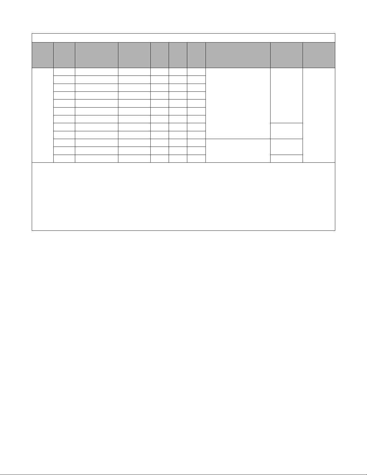
Table 1.3 240V Enclosure Data
Input
Volts
240
1
HP
0.5 E7U22P21 E7L_A002 2.2 2.4 68
0.75 E7U22P21 E7L_A003 3.2 3.5 68
1 E7U22P21 E7L_A004 4.0 4.4 78
2 E7U22P21 E7L_A006 6.8 7.5 110
3 E7U22P21 E7L_A009 9.6 10.6 141
5 E7U23P71 E7L_A015 15.2 16.7 202
7.5 E7U25P51 E7L_A022 22.0 24.2 273
10 E7U27P51 E7L_A028 28.0 30.8 365
15 E7U20111 E7L_A042 42.0 46.2 578
20 E7U20151 E7L_A054 54.0 59.4 653
25 E7U20181 E7L_A068 68.0 74.8 746
30 E7U20221 E7L_A080 80.0 88.0 939 221 lbs
Drive
Model
CIMR-
Bypass
Model
Number
2
NEC
FLA
OL
110 %
1 min
Note 1: Horsepower rating is based on a standard NEMA B 4-pole motor.
Note 2: The underscore position in these model numbers codes for the enclosure type: V = NEMA1, B = NEMA12 FVFF.
Note 3: Heat loss is the amount of heat dissipated by the drive at full load with all standard options available inside the enclosure. Drive heat sink losses are
included in the heat loss data.
Note 4: Height dimension (H) excludes the mounting screw tabs. Depth dimension (D) excludes the disconnect handle.
Note 5: This data represents the total weight with all possible standard options. Weight could be less depending on the options specified.
Note 6: All standard options are available in this size enclosure.
3
Heat
Loss
Watts
Enclosure Dimensions
NEMA 1 & NEMA 12 -FVFF
H W D
29.48 19.06 13.66
Dimension Drawing
40.48 25.63 14.66
Dimension Drawing
inches
S-5537
S-5539
4
6
6
Weight
of
Assembly
115 lbs
127 lbs
208 lbs
5
Electrical
Schematic
E7L-00
Physical Installation 1 - 4
Page 17
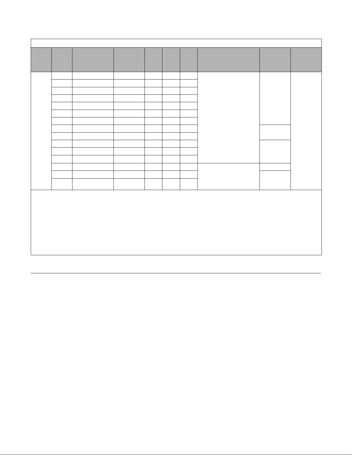
Table 1.4 480V Enclosure Data
Input
Vol ts
480
1
HP
0.5 42P21 E7L_B001 1.1 1.2 57
0.75 42P21 E7L_B001 1.6 1.8 57
1 42P21 E7L_B002 2.1 2.3 62
2 42P21 E7L_B003 3.4 3.7 89
3 42P21 E7L_B004 4.8 5.3 121
5 43P71 E7L_B007 7.6 8.4 155
7.5 45P51 E7L_B011 11.0 12.1 217
10 47P51 E7L_B014 14.0 15.4 318
15 40091 E7L_B021 21.0 23.1 404
20 40 111 E7L_B027 27.0 29.7 408
25 40151 E7L_B034 34.0 37.4 485
30 40181 E7L_B040 40.0 44.0 618
40 40241 E7L_B052 52.0 57.2 1040
50 40301 E7L_B065 65.0 71.5 1045
60 40371 E7L_B077 77.0 84.7 1197
Drive
Model
CIMR-
Bypass
Model
Number
2
NEC
FLA
OL
110%
1 min
Note 1: Horsepower rating is based on a standard NEMA B 4-pole motor.
Note 2: The underscore position in these model numbers codes for the enclosure type: V = NEMA1, B = NEMA12 FVFF.
3
Heat
Loss
Watts
Enclosure Dimensions
NEMA 1 & NEMA 12 -FVFF
H W D
29.48 19.06 13.66
Dimension Drawing
40.48 25.63 14.66
Dimension Drawing
inches
S-5537
S-5539
4
6
6
Weight
of
Assembly
115 lbs
127 lbs
142 lbs
203 lbs
232 lbs
5
Electrical
Schematic
E7L-00
Note 3: Heat loss is the amount of heat dissipated by the drive at full load with all standard options available inside the enclosure. Drive heat sink losses are
included in the heat loss data.
Note 4: Height dimension (H) excludes the mounting screw tabs. Depth dimension (D) excludes the disconnect handle.
Note 5: This data represents the total weight with all possible standard options. Weight could be less depending on the options specified.
Note 6: All standard options are available in this size enclosure.
Bypass Unit Enclosures
All Bypass units are intended for non-hazardous locations. Various enclosure types are provided to protect against the application environmental conditions:
Nema Type 1 Enclosures
These are constructed for indoor use to provide a degree of protection against incidental contact with enclosed electrical equipment and falling dust or dirt.
NEMA Type 12 FVFF Enclosures
NEMA provides for both non-ventilated and ventilated NEMA 12 enclosures. When ventilated, a suffix to the type number
defines the ventilation method. A NEMA 12 FVFF enclosure has Forced Ventilation with inlet air Filter and outlet air Filter.
The internal pressure is positive with respect to the ambient pressure. UL does not recognize NEMA 12 ventilated enclosures,
therefore, these enclosures are designated NEMA 1 for UL purposes.
Physical Installation 1 - 5
Page 18

Confirmations upon Delivery
A.C. INPUT
A.C. OUTPUT
Volts: 480
Hz: 50/60
Phase: 3
Amps: 71.6
Volts: 0-480
Hz: 0-60
Phase: 3
Amps: 65
Serial No: 4W033727440-0002
Model No,: E7LVB065R
Type: E7L BYPASS
W.D.: E7L-00
Inst. Manual: TM.E7L.01, CD.E7.01
UNPN0001
Receiving Checks
Check the following items as soon as the Drive and Bypass unit is delivered.
Table 1.5 Checks
Item Method
Has the correct model of Bypass unit been
delivered?
Is the Bypass unit damaged in any way?
Are any screws or other components loose? Use a screwdriver or the appropriate tool to check for tightness.
If you find any irregularities in the above items, contact the shipping company, the distributor or representative you purchased
the Bypass unit from or your Yaskawa office immediately.
The Bypass unit is thoroughly tested at the factory. Any damages or shortages evident when the equipment is received must be
reported immediately to the commercial carrier that transported the material. Shipping damage is not covered by the Yaskawa
warranty. After unpacking and inspecting for damage, verify that internal wire connections have not come loose during
shipment by spot checking wire terminations with a screwdriver or the appropriate tool.
Check the model number on the nameplate on the right side of the Bypass unit.
Reconcile with packing slip and/or order information.
Inspect the entire exterior of the Bypass unit to see if there are any dents,
scratches or other damage resulting from shipping.
Bypass unit storage must be in a clean and dry location. Maintain the factory packaging and provide covering as needed to
protect the Bypass unit from construction site dirt, water, debris and traffic prior to and during construction.
Nameplate Information
A nameplate is attached to the right side of the enclosure and the inside of the door of each Bypass unit.
The nameplate shown below is an example for a standard Bypass unit.
Fig 1.1 Bypass Nameplate
(Example)
Physical Installation 1 - 6
Page 19
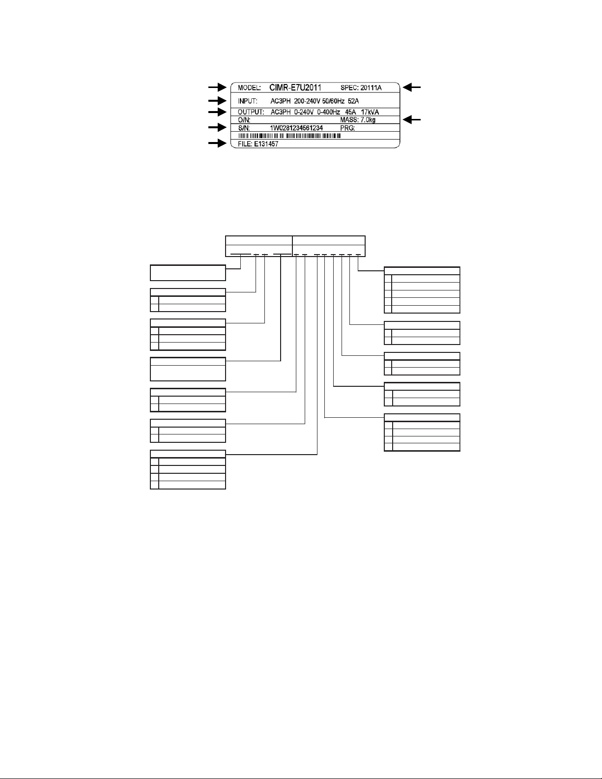
Drive Nameplate Information
Input Power Specifications
Output Power Specifications
Drive Model Number
Drive Enclosure and
Weight
Serial Number
UL File Number
V
B 0 0 GX 0 0 Y L
0
L
V
J
B
0
D
Y
A
B
0
P
0
C
0
0
W
N
0
F
G
H
0
X
Z
R
Enable Metasys N2
3-15 PSI Transducer
Rated Amps (001 - 080)
Current
Voltage
208V
230/240V
480V
E7L 2-Contactor Bypass
Configuration
E 7 L 0 2 1
Enclosure
NEMA 1
NEMA 12
MCP Circuit Breaker
Main Input Disconnect
(Ex.: "021" = 21A)
Disconnect Switch
Drive Keypad
LED Style Keypad
LCD Style Keypad
Drive Input Circuit
3% Bus Re actor
(1)
5% Bus Re actor
(1)
3% Input Reactor
(2)
None
Custom Nameplates
None
None
BASE NUMBER OPTIONS
None
Communications
Not Enabled
LonWorks
3-15 PSI Tr ansducer
Fu
Disconnect Switch
Fuses & Disc. Switch
ses
Custom Nameplates
Input Filter
None
Cap Filter
Impedance
U
V
Enable Modbus
Enable Siemens APOGEE
(1) 3% and 5% Bus Reactors are only available as an option on base numbers up to E7LVA068
and E7LVB040; larger drives have a Bus Reactor as standard
(2) 3% Input Reactor, when combined with the standard Bus Reactor (available on base numbers
E7LVA080 and E7LVB052 and above), yields a total of 5% input impedance
A nameplate is also attached to the right side of the Drive inside the Bypass enclosure. The following nameplate is an example
for a standard Drive.
Revision Code
Fig 1.2 Drive Nameplate
(Example)
Bypass Unit Model Numbers
The model number on the nameplate of the Bypass unit indicates the enclosure, voltage, Drive rated current and options of the
Bypass unit in alphanumeric codes.
Fig 1.3 Bypass Unit Model Number
Physical Installation 1 - 7
Page 20

Bypass Product Options
Option C
Motor Circuit Protector (MCP)/Disconnect: Replaces the standard input disconnect switch and provides short circuit protection
integral with the Drive and Bypass package. The MCP includes a through the door, padlockable operator mechanism. Without
this option, short circuit protection must be provided by others on the input side of the Drive and Bypass unit.
Option F
Drive Input Fuses: Fuses capable of protecting semiconductor devices, rated at 200 kAIC are connected to the line side of the
Drive, between the input disconnect and the Drive, to protect the Drive semiconductors when motor or output conductor short
circuit faults occur.
Option G
Drive Input Disconnect Switch: Provides a disconnect means for the input side of the Drive, for Drive isolation capability
during Bypass operation. This disconnect is located inside the enclosure with no external handle.
Option H
Drive Input Fused Disconnect Switch: Provides both a disconnect means and short circuit protection for the input side of the
Drive. A combination of options F and G.
Option J
Enable Embedded Serial Communications: A no cost option. The Drive in a Bypass unit is capable of network communication
via one of 3 embedded protocols. Specifying option J will enable the Metasys N2 protocol and will provide the necessary
parameter settings and wiring (jumpers) to be network ready when delivered (Project specific H5-0X parameters are setup by
the user).
Option L
Serial Communication, Echelon LonWorks: An isolated RS-422/485 circuit board provides LonTalk protocol for network
communication to a BAS. This option plugs into the CN2 connection on the Drive control circuit board.
Option N
Input Capacitive Network Radio Frequency Interference Filter: Electronic equipment can be sensitive to low levels of voltage
distortion and electrical noise. This passive wye-delta capacitve filter is intended for installation on the VFD input in order to
protect other sensitive electronic loads, it provides attenuation of conducted RFI and EMI.
Option P
Pressure to Electrical Transducer: This transducer is employed when converting a pneumatic signal to an electrical signal for
use as the Drive speed command input. The need for this option comes up on retrofit applications when the pneumatic signal
that formerly controlled the pneumatic actuator on Inlet Guide Vanes (IGV), for example, is now to be used to control the fan
speed via the Drive. This option is wired to terminals TB5-7, TB5-8 and TB5-9, parameters H3-10 and H3-11 are used for
final field calibration of this input if there is jobsite variation from the typical 3 to 15 PSIG pneumatic signal input range.
Option R
3% Input Line Reactor: Employed on the input side of the Drive for Total Harmonic Distortion (THD) suppression. A line
reactor also minimizes the potential for Drive input diode damage from line transients and reduces voltage peaks on the DC
bus capacitors. This option is installed on the input power side of the Drive, between the input contactor and the Drive.
Physical Installation 1 - 8
Page 21

Option U
Enable Embedded Serial Communications: A no cost option. The Drive in a Bypass unit is capable of network communications
via one of 3 embedded protocols. Specifying option U will enable the Siemens APOGEE protocol and provide the necessary
parameter settings and wiring (jumpers) to be network ready when delivered (Project specific H5-0X parameters are setup by
the user).
Option V
Enable Embedded Serial Communications: A no cost option. The Drive in a Bypass unit is capable of network communications
via one of 3 embedded protocols. Specifying option U will enable the Modbus protocol and provide the necessary parameter
settings and wiring (jumpers) to be network ready when delivered (Project specific H5-0X parameters are setup by the user).
Option W
Engraved Plastic Nameplate: An enclosure identification nameplate to carry the controlled equipment “tag number”.
Option X
3% DC Bus Reactor: Attenuates harmonic distortion by limiting the rate of rise of the input current. The bus reactor is wired
to the Drive (+1) and (+2) DC bus terminals to provide the equivalent impedance of a 3% input reactor. This option is only
used on the low end of the horsepower range where DC bus reactors are not a standard Drive component (25 HP and below @
208 VAC, 25 HP and below @ 240 VAC, and 30 HP and below @ 480 VAC.)
Option Y
LCD Keypad: Offers 5 lines of display with 16 characters on each line for expanded data presentation capability in English (or
other language) format.
Option Z
5% DC Bus Reactor: Attenuates harmonic distortion by limiting the rate of rise of the input current. The bus reactor is wired
to the Drive (+1) and (+2) DC bus terminals to provide the equivalent impedance of a 5% input reactor. This option is only
used on the low end of the horsepower range where DC bus reactors are not a standard Drive component (25 HP and below @
208 VAC, 25 HP and below @ 240 VAC, and 30 HP and below @ 480 VAC.)
Physical Installation 1 - 9
Page 22
Bypass Component Descriptions
Drive
Disconnect
Indicating LEDs
H/O/A Keypad
Switch
Keypad
Operator
Drive
Operational
Status
Alpha-Numeric
Menu
Indicating
LEDs
LED Display
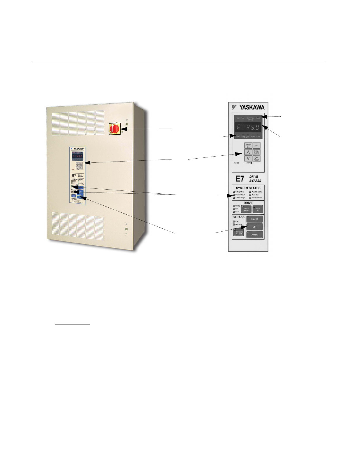
Bypass Unit Front Control Panel
The external appearance, component names, and terminal arrangement of the Bypass unit is shown in Figures 1.4 through 1.8.
Fig 1.4 E7L Bypass Unit Appearance & E7L Control Panel with Keypad Operator Controls
Keypad Control Panel Operator
In a Bypass unit the Drive keypad control panel operator is mounted flush with the hinged door of the enclosure. The Keypad
Control/Operator is equipped with 6 LED illuminated selector keys: Hand, Off, Auto, Drive Select, Bypass Select and Drive
Test. The E7L also features 11 other status LED indicators: Control Power, Drive Ready, Drive Run, Drive Fault, Bypass Run,
Motor O/L, Safety Open, Damper/BAS Interlock, Smoke Purge, Auto Transfer and Auto Run. The membrane over the Drive
keypad is
keypad, part number CDR001115).
The Keypad Control/Operator has a digital alpha/numeric display and keypad, in the upper portion, for Drive operation and
programming. The row of LEDs above the alpha/numeric display indicate Drive operational status. The row of LEDs below
the alpha/numeric display indicate the Drive menu that is presently active.
The lower portion of the Keypad Control/Operator displays the operating mode status via LEDs and controls the HAND/OFF/
AUTO functions for both the Drive and Bypass via a touchpad. The general rule for LED colors, in the lower portion of the
control panel, is:
non-removable on these Bypass units (In order to use the keypad copy function on a Bypass unit - order a separate
Green = Normal Status
Amber = Abnormal Status
Red = Fault Status
Physical Installation 1 - 10
Page 23
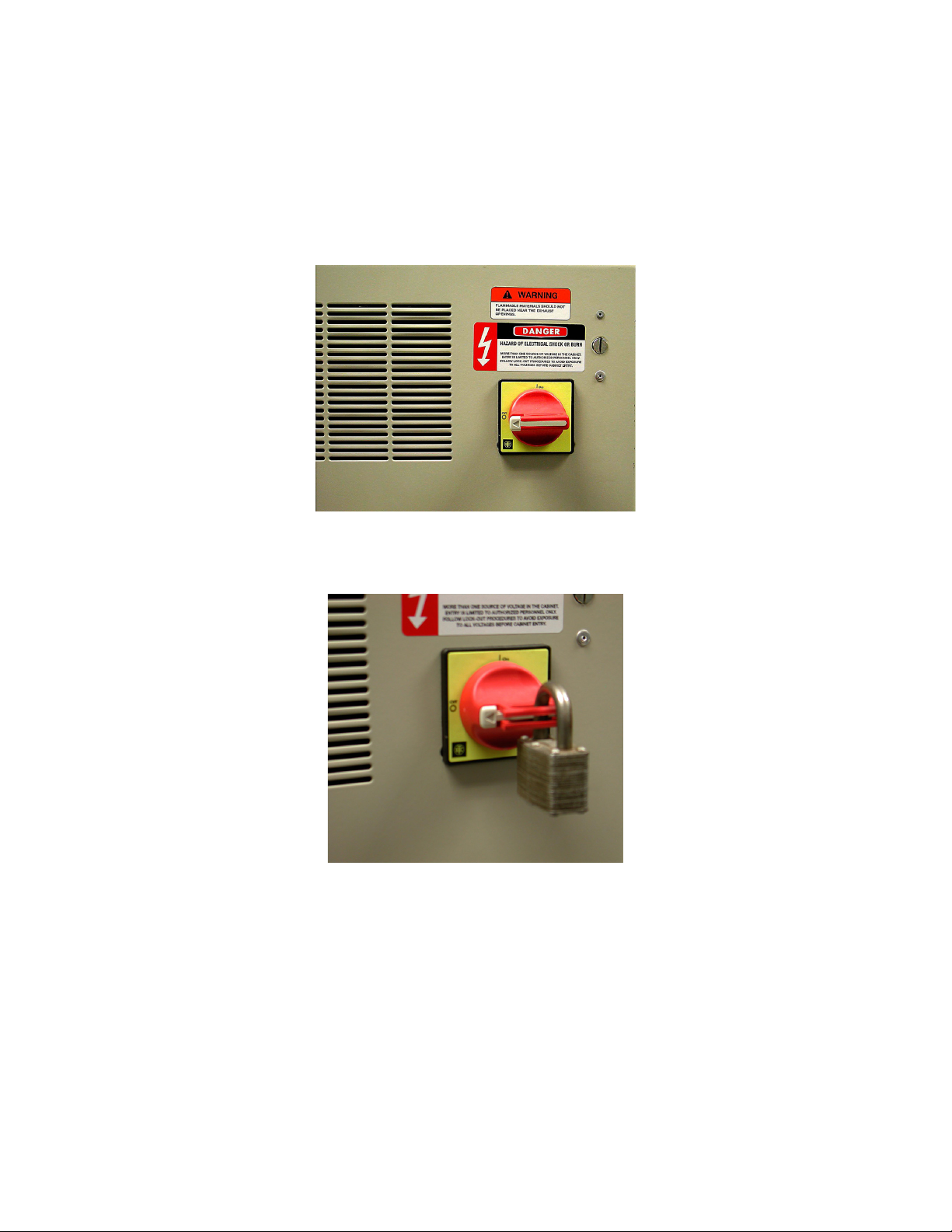
Input Disconnect Switch
Electrically located on the input power side of the Bypass unit, the disconnect provides a through the door padlockable operator
mechanism. The Bypass three phase input power connection is made to the input terminals of the disconnect. The door mounted
rotary operating mechanism is a convenient means of disconnecting the Bypass unit from line power for equipment maintenance.
The disconnect must be in the OFF position in order to open the enclosure door. The rotary handle can be padlocked in the OFF
position.
This disconnect switch DOES NOT provide branch short circuit protection. A device to provide branch short circuit protection
MUST be provided by others upstream of the E7L Bypass unit.
Fig 1.5 Disconnect Handle Positions – OFF, ON Shown in the “OFF” position
Fig 1.6 Disconnect Handle Positions – Shown OFF, With Padlock
Physical Installation 1 - 11
Page 24
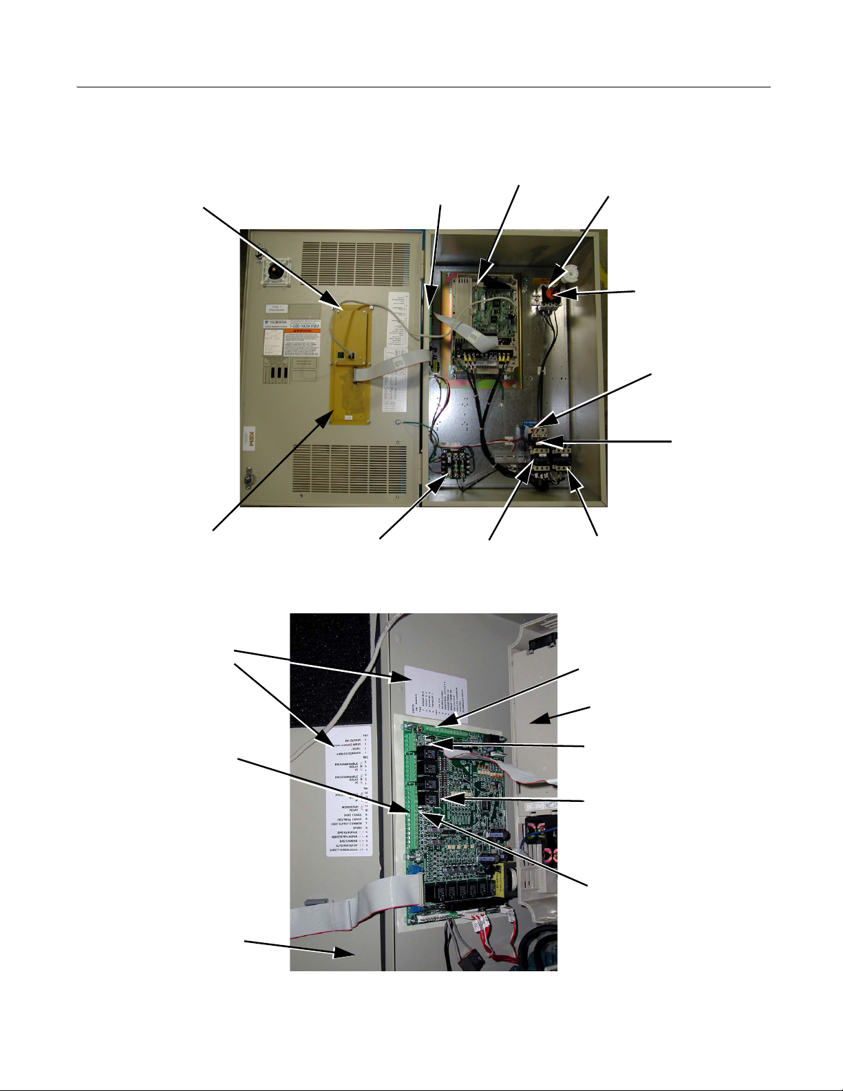
Internal Bypass Panel
Drive Digital
Keypad
PCB A3
Control Wiring
Terminal Strips
TB1 through TB5
Control Power
Transformer
Fig 1.7 Internal Bypass Panel
Bypass
Contactor
Drive
Line
Connections
Input
Disconnect
Load
Connections
Overload
Relay
Output
Contactor
Label Defining
Customer Control
Circuit Connection
Points
TB1, TB2 and TB3
Hinged Enclosure
Door
TB4, TB5 and Terminal PE
Drive
Jumpers J2 and J3,
Analog Output Signal Level
DIP Switches S1, S2, S3
and S4 for Field
Configuration of
Drive/Bypass Operation
Jumper J1, Digital Input
Voltage Source Selection
Fig 1.8 PCB A2 Control Logic and Connections
Physical Installation 1 - 12
Page 25

Contactors
The Bypass is a “2 contactor Bypass” circuit employing IEC rated contactors in an electrically interlocked arrangement to
allow mutually exclusive operation in Drive or Bypass modes. To minimize enclosure space requirements, they are mounted in
a 2 contactor assembly.
The control logic and “soft start” characteristic of the Drive limit the Drive input and output contactors to motor FLA current or
less. For this reason, the Drive output contactor has a lower current rating than the Bypass contactor. The Bypass contactor is
exposed to motor inrush current (LRA) when starting the motor across-the-line and therefore requires a higher current rating.
OverLoad Relay
The OverLoad Relay (OLR) is mounted to the contactor assembly or back panel (depending on rating), just above the Bypass
contactor (see Figure 1.7). Electrically on the output power side of the Bypass unit, the adjustable thermal OLR provides
overload protection for the motor in both the Drive and Bypass operating modes. The Bypass three phase output power
connection to the motor is made to the output terminals of the overload relay. The OLR is set up in the factory to be a manual
reset device, requiring operator attention if an overload trip-out is experienced.
Control Power Transformer
A Control Power Transformer (CPT) is provided to power the Bypass 120 VAC control circuit. The VA capacity is determined
by the control circuit and optional functions specified for the unit. The CPT primary is fused in both legs, the secondary is
fused when required by NEC (transformer VA and wire size dependent). One side of the transformer secondary is grounded to
the Bypass enclosure.
Electronic Bypass Control Logic
Operating elements such as indicating LEDs and selector buttons, as well as the control logic, have been incorporated into a
PCB assembly to eliminate the potential for loose wires after shipment and to control factory costs.
The operating elements are located on PCB A3, mounted to the inside of the enclosure door and ribbon cable connected to the
control logic PCB A2.
The control logic PCB A2 is mounted to the left hand side of the enclosure and contains the control circuit field wiring terminal strips (TB1 through TB5).
Drive/Bypass logic interlocks explained
The Bypass 120 VAC logic circuit is interconnected with the Drive multi-function digital input terminals and multifunction digital output terminals to allow a single customer interface to control both Drive and Bypass circuits. These Drive
terminals are therefore not available for other field use. All field control connections are landed at terminal strips TB1 through
TB5 on control logic PCB A2.
PCB Jumpers explained
J1 is a field configuration jumper to allow the user to select the internal 120 VAC power supply, a customer supplied 120 VAC
power supply or a customer supplied 24 VDC power supply for the digital inputs.
J2 and J3 are field configuration jumpers to allow the user to select the signal level (0 to 10 VDC or 4 to 20 mA) for the two
analog output signals.
Physical Installation 1 - 13
Page 26
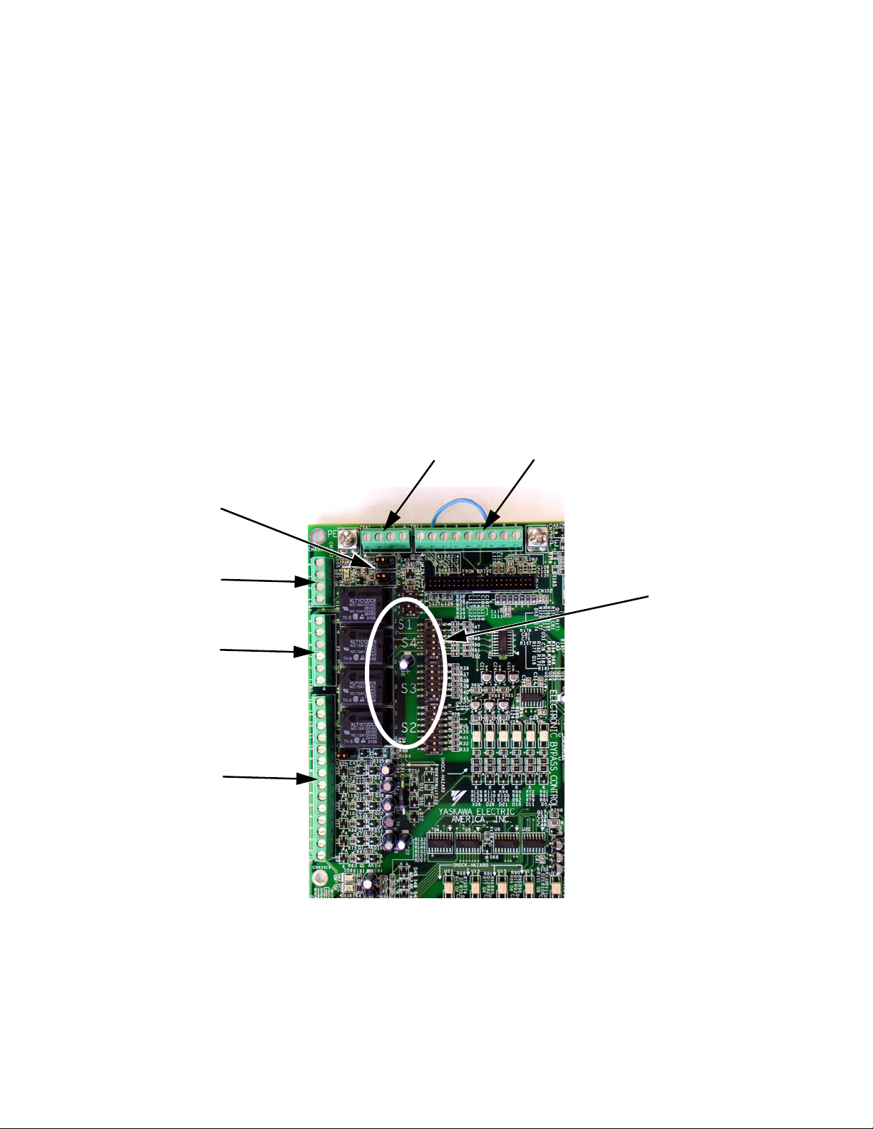
DIP Switch Selectable Functions:
The DIP switches used to select these functions are located on the logic controller Printed Circuit Board (PCB) A2 (See Figure
1.9). The factory default is shown on the wiring diagram in Chapter 2 or Schematic diagram E7L-00.
DIP switches S1, S2, S3 and S4 allow the user to configure various project specific functions of the E7L including:
• Serial Communication terminating resistor
• Speed command source
• Analog input signal level
• Activate or inactivate functions:
Auto transfer to Bypass on Drive Fault
Safety interlock circuit
BAS interlock circuit
• Power-up mode selection
• Function of 3 SPDT programmable output relays:
Annunciate Running in Bypass mode
Damper actuator energized - employed to energize damper actuator
Annunciate Auto-Transfer to Bypass
Annunciate Running in Drive mode
Annunciate Run command received from serial comm
Annunciate Hand mode
Annunciate Auto mode
Annunciate Drive, motor or control fault
TB4
TB5
J2 and J3
TB3
TB2
TB1
DIP Switch
Location on
PCB A2
Fig 1.9 Printed Circuit Board A2, DIP Switches for Drive/Bypass Operational Configuration
Physical Installation 1 - 14
Page 27
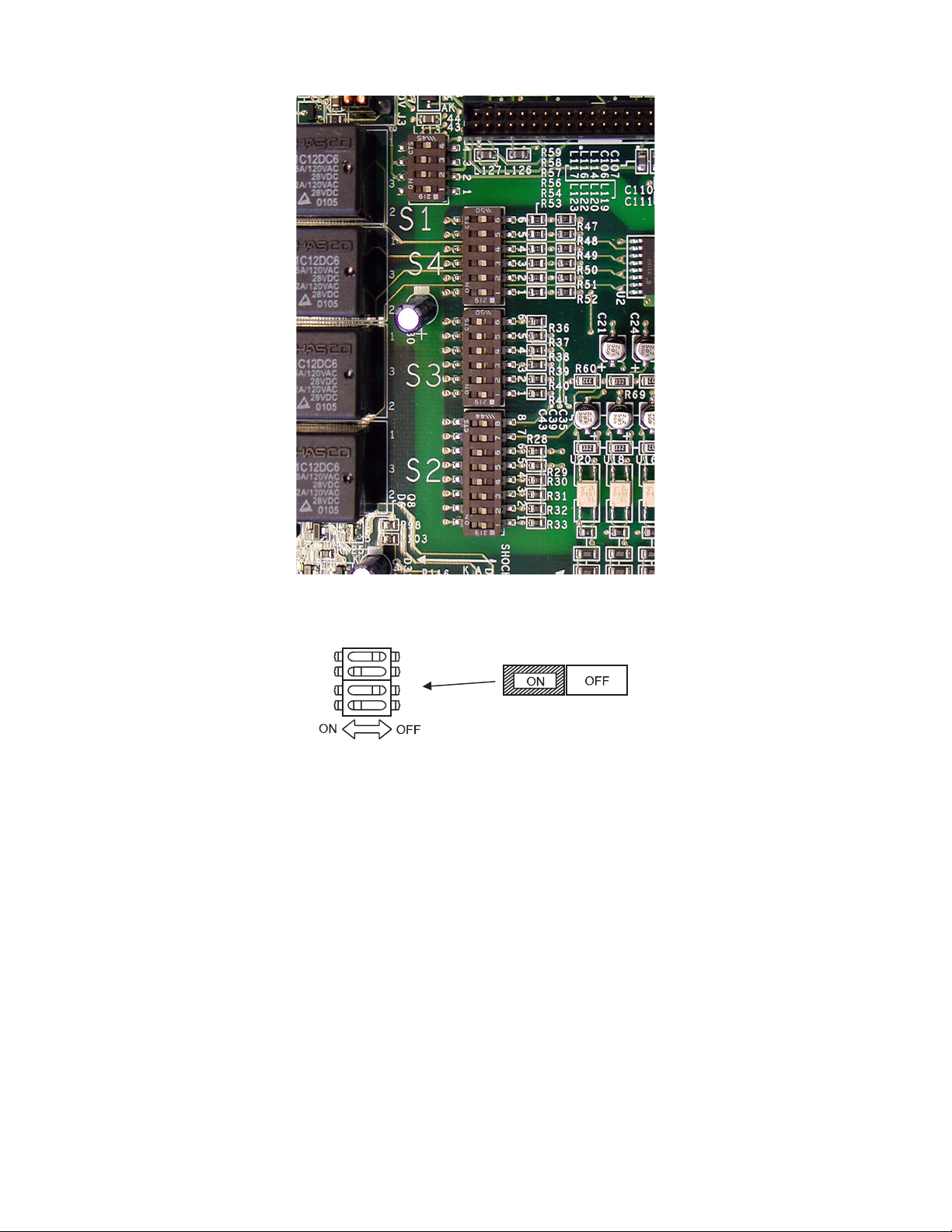
DIP Switches are “ON” when moved toward the enclosure door.
4
3
2
1
Fig 1.10 DIP Switches S1 to S4 for Drive/Bypass Operational Configuration
DIP Switch S1 example
Physical Installation 1 - 15
Page 28
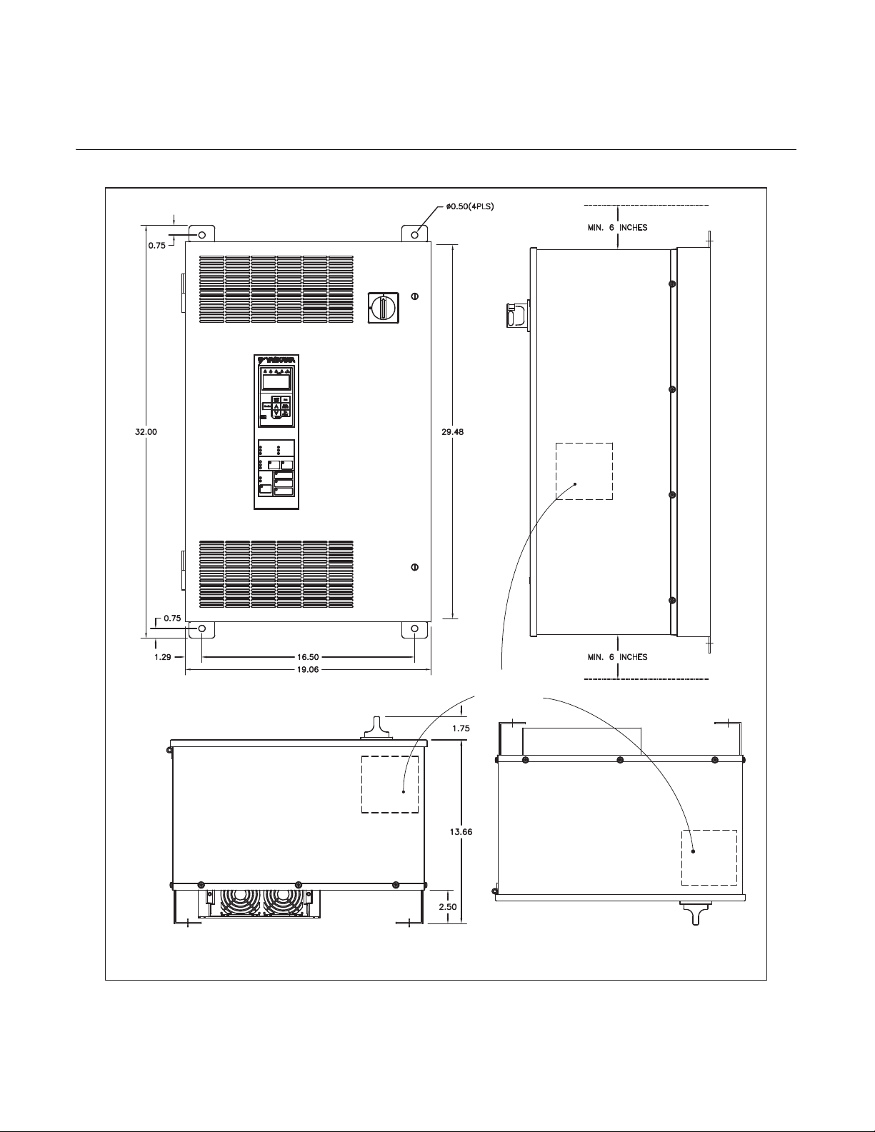
Exterior and Mounting Dimensions
RECOMMENDED
CONDUIT
ENTRANCE AREA
TOP, BOTTOM
AND SIDE
DIMENSIONS IN INCHES (MM), FOR REFERENCE ONLY
TOP VIEW
Bypass Unit 30 HP and Below, 480 VAC; 15 HP and Below, 208V/240V
Fig 1.11 Enclosure 1 for up to 30HP, 480 VAC
NEMA 1 and NEMA 12 FVFF Enclosures
Physical Installation 1 - 16
Page 29
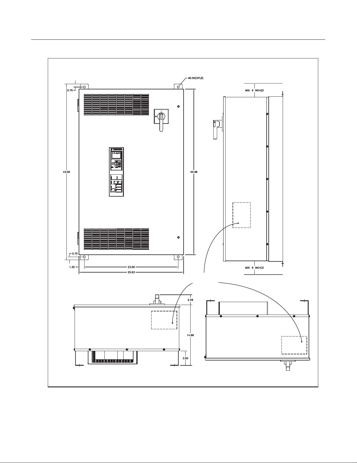
Bypass Unit 40 HP to 60 HP, 480 VAC; 20 HP to 30 HP, 208V/240V
DIMENSIONS IN INCHES (MM), FOR REFERENCE ONLY
RECOMMENDED
CONDUIT
ENTRANCE AREA
TOP, BOTTOM
AND SIDE
TOP VIEW
Fig 1.12 Enclosure 2, for 40HP to 60HP, 480 VAC
NEMA 1 and NEMA 12 FVFF Enclosures
Physical Installation 1 - 17
Page 30

Dimensions and Weights
Rated
Input
Voltage
208V
240V
480V
Continuous
Output
Current
(Amps)
2.4 1/2 D002
3.5 3/4 D003
4.6 1 D004
7.5 2 D007
10.6 3 D010
16.7 5 D016
24.2 7.5 D024
30.8 10 D030
46.2 15 D046
59.4 20 D059
74.8 25 D074
2.2 1/2 A002
3.2 3/4 A003
4.0 1 A004
6.8 2 A006
9.6 3 A009
15.2 5 A015
22 7.5 A022
28 10 A028
42 15 A042
54 20 A054
68 25 A068
80 30 A080 221
1.1 1/2 B001
1.6 3/4
2.1 1 B002
3.4 2 B003
4.8 3 B004
7.6 5 B007
11 7.5 B011
14 10 B014
21 15 B021
27 20 B027
40 30 B040
52 40 B052
65 50 B065
77 60 B077
Nominal
(1)
HP
Bypass
_ _ _
Table 1.6 Bypass Dimensions and Weights
NEMA 1 and NEMA 12
_
Dimensions inches (mm)
(2)
Height
32.00
(812.8)
43.00
(1092.2)
32.00
(812.8)
43.00
(1092.2)
32.00
(812.8)
43.00
(1092.2)
Width Depth
19.06
(484.1)
25.63
(651.0)
19.06
(484.1)
25.63
(651.0)
19.06
(484.1)
25.63
(651.0)
16.03
(407.2)
17.03
(432.6)
16.03
(407.2)
17.03
(432.6)
16.03
(407.2)
17.03
(432.6)
Mounting Dimen
Wall
sions
H x W
30.5 x 16.5
(774.7) x (419.1)
41.5 x 23.0
(1054.1 x 584.2)
30.5 x 16.5
(774.7) x (419.1)
41.5 x 23.0
(1054.1 x 584.2)
30.5 x 16.5
(774.7) x (419.1)
41.5 x 23.0
(1054.1 x 584.2)
-
Drawing
Number
S-5537
S-5539 208
S-5537
S-5539
S-5537
S-5539
Weight
(3)
(lbs)
115
127
115
127
208
115
127
14234 25 B034
203
232
(1) Horsepower rating is based on standard NEMA B 4-pole motor design
(2) Height dimension includes the mounting screw tabs.
(3) Data represents the total weight of the drive with all possible standard options, not shipping weight.
Physical Installation 1 - 18
Page 31

Checking and Controlling Installation Site
Install the Bypass unit as described below and maintain the specified operating conditions.
Installation Site
Location of the Bypass unit is important to achieving proper performance and design operating life. Install the Bypass unit as
close as possible to the motor. The NEMA type 1 & 12 enclosed units should be installed in an area where it will be protected
from: Direct sunlight, rain or moisture, corrosive gasses or liquids, vibration and dust or metallic particles. The ambient air
available for cooling the unit should be 104° F (40° C) or less.
Wall mount units require a minimum 6 inch clearance above and below, to achieve adequate heat sink cooling.
No side clearance is required for cooling because the cooling air flow is in and out of the enclosure door at the front surface of
the unit (do not block the air flow louvers). Clearance for the opening swing of the enclosure door should be considered when
placing these units. The door is hinged on the left and must open through at least a 90 degree swing with a 120 to 180 degree
swing being preferable (minimum clearance is 1.5”).
Install the Bypass unit under the following conditions in UL pollution degree 1 & 2 environments. This excludes wet locations
where surfaces may become conductive due to moisture and contaminant loading.
Table 1.7 Installation Site
Type Ambient Operating Temperature Humidity Plenum Rated
NEMA Type 1 & 12 14 to 104°F (-10-to-+ 40°C) 95%-RH-or-less-(no-condensation) Ye s
Observe the following precautions when mounting the Bypass unit.
• Install the Bypass unit in a clean location that is free from oil mist and dust.
• Install the Bypass unit in an environment where metal shavings, oil, water, or other foreign matter will not get into the
Bypass enclosure.
• Install the Bypass unit in a location free from radioactive materials.
• Install the Bypass unit in a location free from harmful gasses and liquids.
• Install the Bypass unit in a location without excessive vibration.
• Install the Bypass unit in a location free from chlorides.
• Install the Bypass unit in a location not in direct sunlight.
• Install the Bypass unit on a non-combustible surface.
Physical Installation 1 - 19
Page 32

Controlling the Ambient Temperature
To enhance the reliability of operation, the Bypass unit should be installed in an environment free from extreme temperature
variations. Do not store this Technical Manual or any other documents on the top surface of the Bypass unit, they may cover
the heat sink cooling air discharge opening and cause the unit to overheat.
If the Bypass unit is installed in an enclosure (such as an electrical control box in an air handling unit), use a cooling fan or air
conditioner to maintain the Bypass unit internal air temperature below 113°F (45°C).
Protecting the Bypass Unit from Foreign Matter
During Bypass unit installation and project construction, it is possible to have foreign matter, such as metal shavings or wire
clippings, fall inside the Bypass unit. To prevent foreign matter from falling into the Bypass unit, place a temporary cover over
the unit.
Always remove the temporary cover from the Bypass unit before start-up. Otherwise, ventilation will be reduced, causing the
Bypass unit to overheat.
Installation Orientation and Enclosure Considerations
Install the Bypass unit vertically so as not to reduce the cooling efficiency. When installing the Bypass unit, always provide the
recommended installation clearances to allow normal heat dissipation.
When preparing to mount the unit, lift it by the base (or lifting rings when provided), never by the enclosure door. For effective
cooling and proper maintenance, the wall mounted units must be installed on a flat non-flammable vertical surface using four
mounting screws.
For all units, the Disconnect handle should be in the OFF position to open the enclosure door. The wall mount units have two
full turn fasteners, CCW to open, that require a flat blade screwdriver to open the enclosure door.
Physical Installation 1 - 20
Page 33

Chapter 2
Electrical Installation
This chapter describes wiring and the electrical installation process for a Drive and
Bypass unit.
Termination Configuration - Power Wiring ..................................... 2
Field Wiring, Pressure Wire Connector, Wire Type, Range
and Tightnening Torque Specifications ..................................... 3
Cable Length between Drive and Motor .................................... 4
Grounding ................................................................................. 5
Wire Routing ............................................................................. 6
E7 Drive Main Circuit Configurations 208-240 VAC .................. 7
E7 Drive Main Circuit Configurations 480 VAC ......................... 7
Control Wiring ................................................................................ 8
Bypass Field Control Wire Landing ........................................... 8
Annunciation Contacts .............................................................. 9
Building Automation System Run/Stop Circuit: ....................... 10
Safety Interlock Circuit: ........................................................... 10
Building Automation System Interlock Circuit
(Drive and Bypass enable input): ............................................ 10
Analog Inputs .......................................................................... 11
Analog Outputs ........................................................................ 13
Serial Communications ............................................................ 14
Remote Transfer to Bypass...................................................... 16
Smoke Purge Operation........................................................... 16
Multi-Function Digital Inputs..................................................... 16
DIP Switch Programmable Functions Summary...................... 17
Bypass Controller PCB ........................................................... 18
Wiring Checks ......................................................................... 19
Control Circuit Wiring Precautions .......................................... 19
Bypass Control Circuit Terminal Functions ............................. 20
Wiring Diagram ............................................................................ 23
Electrical Overview ....................................................................... 25
Electrical Installation 2 - 1
Page 34

Termination Configuration - Power Wiring
Overload
Relay
The input disconnect switch is located in the upper right hand side of the Bypass unit. The three phase input power
connection is made to the input terminals of the disconnect. See Figure 2.1 for a representative example.
Ground Lug
Drive
Fig 2.1 Typical Input Power Connection
The OverLoad Relay (OLR) is mounted to the contactor assembly or back panel (depending on rating), just above the bypass
contactor. The Bypass three phase output power connection to the motor is made to the output terminals of the OverLoad
Relay. See Figure 2.3 for representative examples.
Input Power Terminals
Input Disconnect
Switch
Disconnect Switch
“Through the Door”
Handle
Overload Relay
Motor Connections
Bypass
Contactor
Output Contactor
Fig 2.3 Typical Output Power Connection
Electrical Installation 2 - 2
Motor Connections
Bypass
Contactor
Output Contactor
Page 35

Field Wiring, Pressure Wire Connector, Wire Type, Range and Tightnening
208V 480V
MFG.
PART
NUMBER
WIRE SIZE
RANGE
(AWG)
MFG.
PART
NUMBER
WIRE SIZE
RANGE
(AWG)
208V
TIGHTENING
TORQUE
(LB.-IN.)
240V
480V240V
D002
D003
D004
D007
D010
D016
D024
D030
D046
D059
D074
A002
A003
A004
A006
A009
A015
A022
A028
A042
A054
A068
A080
B001
B002
B003
B004
B007
B011
B014
B021
B027
B034
B040
B052
B065
B077
FAL36003
FAL36007
FAL36030
FAL36015
FAL36050
FAL36100
KAL36150
14 - 4
12 - 4
12 - 1/0
4 - 350 kcmil
35
35
80
250
TIGHTENING
TORQUE
(LB.-IN.)
D002
D003
D004
D007
D010
D016
D024
D030
D046
D059
D074
A002
A003
A004
A006
A009
A015
A022
A028
A042
A054
A068
A080
B001
B002
B003
B004
B007
B011
B014
B021
B027
B034
B040
B052
B065
B077
LR2 D13
LR2 D15
LR2 D25
LR2 D35
18 - 10
18 - 10
14 - 6
10 - 1/0
15
CURRENT
RATING
(AMPS)
3
7
15
30
50
100
150
=
=
V (NEMA 1) OR B (NEMA 12)
V (NEMA 1) OR B (NEMA 12)WHERE
WHERE
100
E7 BYPASS MODEL NO.
BASE NUMBER
E7L XXXX
E7 BYPASS MODEL NO.
BASE NUMBER
E7L XXXX
35
12 - 4
30FAL36030
80
12 - 1/0
50FAL36050
80
12 - 1/0
100FAL36100
FAL36100 100
12 - 1/0
80
MFG.
PART
NUMBER
V0
V3
V4
V5
V6
CURRENT
RATING
(AMPS)
WIRE SIZE
RANGE
(AWG)
TIGHTENING
TORQUE
(LB.-IN.)
20
45
63
100
115
14 - 8 19
8 - 2/0 200
40
6 - 2 50
12 - 6
STANDARD INPUT DISCONNECT SWITCHOPTIONAL MOTOR CIRCUIT PROTECTOR - OPTION C
WIRE SIZE
RANGE
(AWG)
TIGHTENING
TORQUE
(LB.-IN.)
V4 63
6 - 2 50
V6 115
8 - 2/0 200
14 - 10 35
8
6 - 4 45
GROUND LUG
12 - 1/0
80
CUSTOMER CONTROL WIRING
TERMINAL BLOCKS TB1 - TB5
WIRE SIZE
RANGE
(AWG)
TIGHTENING
TORQUE
(LB.-IN.)
4.422 - 14
MOTOR OVERLOAD RELAY
EARTH GND. WIRINGCUSTOMER A.C. LINE WIRING
CUSTOMER A.C. MOTOR WIRING
FOR 0 TO 100 AMPS, USE 60-75 C COPPER WIRE, AND ABOVE 100 AMPS, USE 75 C COPPER WIRE.
40
Torque Specifications
IMPORTANT
WARNING
Determine the wire size for the main circuit so that line voltage drop is within 2% of the rated voltage. Line
voltage drop is calculated as follows:
Line voltage drop(V) = √3 x wire resistance (Ω/km) x wire length (m) x current (A) x 10
Prior to removing any protective cover or wiring any part of the Drive, remove all power sources, including
main input power and control circuit power. Wait a minimum of 5 minutes after power removal, before
removing any cover. The charge lamp located within the Drive should be off prior to working inside. Even if
the charge lamp is off, one must measure the AC input, output, and DC Bus potential to insure safe levels
prior to resuming work. Failure to adhere to this warning may result in personal injury or death.
Electrical Installation 2 - 3
-3
Page 36

Cable Length between Drive and Motor
The Bypass unit should be installed as close as possible to the motor to minimize the length of load side power cable needed
between the Drive and the motor. If the cable between the Drive and the motor is long, the high-frequency leakage current will
increase, causing the Drive output current to increase as well. This may affect peripheral devices. To prevent this, reduce cable
length, or if necessary, adjust the carrier frequency (set in C6-02) as shown in Table 2.1.
The line side power cables, load side power cables and the control wiring should all be run in a separate conduit. Careful
attention to this recommended design practice will avoid many potential motor and Drive related problems.
Table 2.1 Motor Cable Length vs. Carrier Frequency (C6-02)
Motor Cable Length 164 ft. (50m) maximum 328 ft. (100m) maximum More than 328 ft.(100m)
Carrier Frequency 15kHz maximum 10kHz maximum 5kHz maximum
(See the limitations on carrier frequency, based on Drive capacity and model number in Appendix B).
Electrical Installation 2 - 4
Page 37

Grounding
NO
Drive and Motor Ground Wire Landing
The Drive ground lug (terminal ) is connected to the enclosure. The enclosure ground lug must be connected to earth
ground. See Figure 2.1.
The Drive has a second ground lug to accept the motor ground lead.
Ground Wiring Precautions
Observe the following precautions when connecting the ground wire:
1. 208-240 VAC Drives should have a ground connection with resistance of less than 100 Ω..
2. 480 VAC Drives should have a ground connection with resistance of less than 10 Ω..
3. Do not share the ground wire with other devices, such as large-current electrical equipment.
4. Always use a ground wire that complies with technical standards on electrical equipment and minimize the length of the
ground wire. Leakage current flows through the Drive. Therefore, if the distance between the ground rod and the ground
terminal is too long, potential on the ground terminal of the Drive will become unstable.
5. When using more than one Drive, be careful not to loop the ground wire.
OK
For grounding connection to earth ground see Figure 2.1.
NO
OK
Fig 2.4 Ground Wiring Examples
NO
Control Circuit Ground Terminals
The control logic PCB A2 provides a ground terminal (marked PE) to accept the control wire shield connection. Terminal PE
is located at the top left of PCB A2, near TB4. The control wire shield should be connected on this end only, the opposite end
should be isolated with electrical tape.
IMPORTANT
Grounding of the Bypass enclosure and motor is required for proper system operation.
Electrical Installation 2 - 5
Page 38

Wire Routing
Input
power
Motor
connection
Control
circuit
wiring
The following Figures indicate suggested wire entry and bending areas for representative wall mount enclosures.
Fig 2.5 Typical Wall Mount Enclosure
Electrical Installation 2 - 6
Page 39

E7 Drive Main Circuit Configurations 208-240 VAC
Power
supply
Control
circuits
{
1
Note
CIMR-_ _ _ 20P4 to 2018
(1/2 Hp to 25 Hp)
Power
supply
Control
circuits
{
Note
1
CIMR-_ _ _ 4030 to 4037
(40 Hp to 60 Hp)
Power
supply
Control
circuits
{
Notes
1 & 3
Table 2.2 Drive Main Circuit Configurations
208-240 VAC
Notes
1 & 3
{
Note 1. Input fuses or molded case circuit breakers are required for proper branch circuit protection for all Drives. Failure
to use recommended fuses/circuit breakers (See Appendix E) may result in damage to the wiring, Drive and/or
personal injury.
2. Control power is supplied internally from the main circuit DC power supply for all Drives.
3. Consult your Yaskawa representative before using 12-pulse rectification.
E7 Drive Main Circuit Configurations 480 VAC
CIMR-_ _ _ 2022 (30 Hp)
Control
Power
circuits
supply
CIMR-_ _ _ 40P4 to 4018
Note 1. Input fuses or molded case circuit breakers are required for proper branch circuit protection for all Drives. Failure
to use recommended fuses/circuit breakers (See Appendix E) may result in damage to the wiring, Drive and/or
personal injury.
2. Control power is supplied internally from the main circuit DC power supply for all Drives.
3. Consult your Yaskawa representative before using 12-pulse rectification.
Table 2.3 Drive Main Circuit Configurations
480 VAC
(1/2 Hp to 30 Hp)
Electrical Installation 2 - 7
Page 40

Control Wiring
Bypass Field Control Wire Landing
The Bypass field control wiring is terminated on the control PCB A2, Terminal blocks TB1 through TB5. The terminal designations are labeled on the enclosure, adjacent to PCB A2 (see Figure 2.6). Route the control wiring as shown in Figure 2.5.
Fig 2.6 TB1 Control Terminal Locations, All Models
Electrical Installation 2 - 8
Page 41

Annunciation Contacts
Contacts for customer use are provided and wired to TB1 and TB2 as follows for use as annunciators of Bypass unit operation.
All are 5 amp at 120 VAC contacts.
Table 2.4 Output Relays - Factory Defaults
Function Name (E7L-00) Terminal Block Terminals Type
Motor Run Motor Run * TB1 10-11 Form A
Hand Mode Relay 1 @ TB1 12-13-14 Form C
Auto Mode Relay 2 @ TB2 1-2-3 Form C
System Fault Relay 3 @ TB2 4-5-6 Form C
* = Dedicated
@ = Programmable
Programmable Output Relays 1, 2 and 3 may be re-programmed via DIP switches S2 and S3 on the Bypass Control PCB A2.
These relays provide form C “dry contacts” for customer use in annunciation to Building Automation Systems or general duty
in other control logic circuits. Each contact is rated for 5 amps at 120 VAC.
The additional programmable output relay functions are described in the table below:
Table 2.5 Programmable Output Relay Functions
Function Description Factory Default
Bypass Run Annunciates running in Bypass mode No
Intended to close a contact in a damper actuator circuit
Damper Actuator
Auto Transfer
Drive Run Annunciates running in Drive mode No
Serial Com Run
Hand Mode
Auto Mode
System Fault
whenever the motor is commanded to run (operation similar
to the dedicated “Motor Run” relay)
Annunciates automatic transfer to Bypass operation due to a
Drive fault
Annunciates that the run command is coming from serial
communications
Annunciates that the Drive or Bypass is being operated in
Hand (local) mode
Annunciates that the Drive or Bypass is being operated in
Auto (remote) mode
Annunciates that a Drive, motor overload or control circuit
fault has occurred
No
No
No
Relay 1
Relay 2
Relay 3
See Table 2.6 for DIP switch positions required to achieve these functions.
Table 2.6 DIP Switch Settings for Output Relay Functions
Programmable
No. Function
1 Bypass Run OFF OFF OFF OFF OFF OFF OFF OFF OFF ENERGIZED Running in Bypass mode
2 Damper Coil OFF OFF ON OFF OFF ON OFF OFF ON ENERGIZED Damper actuator activation
3 Auto Transfer OFF ON OFF OFF ON OFF OFF ON OFF ENERGIZED Auto-Transfer is active
4 Drive Run OFF ON ON OFF ON ON OFF ON ON ENERGIZED Drive is in the Run mode
5 Serial Com. Run ON OFF OFF ON OFF OFF ON OFF OFF ENERGIZED Serial Comm. Run command
6 Hand Mode ON OFF ON ON OFF ON ON OFF ON ENERGIZED Manual mode operation
7 Auto Mode ON ON OFF ON ON OFF ON ON OFF ENERGIZED Auto mode operation
8 System Fault ON ON ON ON ON ON ON ON ON DEENERGIZED Drive, motor or control fault
Factory Settings ON OFF ON ON ON OFF ON ON ON
* ACTIVE = RELAY CONDITION DURING FUNCTION
Relay 1
S2(6) S2(5) S2(4) S3(3) S3(2) S3(1) S3(6) S3(5) S3(4)
Programmable
Relay 2
Programmable
Relay 3
Active*
Function
Description
Electrical Installation 2 - 9
Page 42

Building Automation system Run/Stop circuit:
A control terminal block position (TB1, terminals 2 and 9) is provided to connect the Normally Open (NO) Run/Stop contact
from a BAS or other remote controller for auto mode control.
There must be continuity between these terminals in order for the motor to run, in auto mode.
Safety Interlock Circuit:
A control terminal block position (TB1, terminals 1 and 9) is provided to connect the series circuit of Normally Closed (NC)
safety devices such as: freeze up thermostats, smoke/fire sensors, high pressure limits, temperature limits or vibration
detectors.
On power up the E7L will display a red “Safety Open” LED in the “System Status” area of the front control panel if a normally
closed “Safety Circuit” has not been installed between TB1-1 and TB1-9 on PCB A2. This condition will prevent Drive or
Bypass operation.
1 of 3 items needs to be done before the motor can be started:
1) Install a NC “Safety Circuit” between TB1-1 and TB1-9 on PCB A2.
2) Install a jumper between TB1-1 and TB1-9 on PCB A2. This method should be used if a “Safety Circuit” will be
added later in the installation.
3) De-activate these terminals by moving DIP switch S2-7 to the ON position (toward the enclosure door). This solution
is only suggested if a “Safety Circuit” will
never be applied to the drive system.
Building Automation System Interlock Circuit (Drive and Bypass enable input):
A control terminal block position (TB1, terminals 3 and 9) is provided to connect Normally Open (NO) enabling contacts such
as: damper end switches or occupied cycle timers.
When a Run command is received in HAND or AUTO mode, the E7L will display a red “Damper/BAS” LED in the “System
Status” area of the front control panel. This condition will prevent Drive or Bypass operation.
1 of 3 items needs to be done before the motor can be started:
1) Install a “BAS Interlock Circuit” between TB1-3 and TB1-9 on PCB A2.
2) Install a jumper between TB1-3 and TB1-9 on PCB A2. This method should be used if a “BAS Interlock Circuit” will
be added later in the installation.
3) De-activate these terminals by moving DIP switch S2-8 to the ON position (toward the enclosure door). This solution
is only suggested if a “Safety Circuit” will
never be applied to the drive system.
Electrical Installation 2 - 10
Page 43

Analog Inputs
The Drive has two analog input terminals for use as auto mode speed command (terminals A1 & A2) and feedback (terminal
A2) input.
Table 2.7 Drive Analog Input Terminals
Terminal Signal Level
A1 0 to 10 VDC
A2
(programmable via parameter H3-08 and DIP switch S1-2)
Control Circuit Analog Input Terminals on PCB A2
All control inputs are landed on TB1 through TB5 on PCB A2.
TB3-3 is an analog input terminal and may be connected to either Drive terminal A1 or Drive Terminal A2, to maximize input
flexibility, using DIP switches S1-3 and S1-4. The factory default is TB3-3 connected to Drive terminal A2. With this
connection, the input signal level can be either 0 to 10 VDC or 4 to 20 mA. The signal level selection is controlled by DIP
switch S1-2 and Drive parameter H3-08.
TB5-9 is also an analog input terminal, it is always connected to Drive terminal A2.
See Table 2.8, Figure 2.7 and Schematic Diagram E7L-00 for clarification of the analog input configuration and applications.
Table 2.8 Analog Input - Auto Mode
DIP Switches Drive Drive Applications
Param. Terminal Speed
S1-2 S1-3 S1-4
TB3-3
Signal Level
0 to 10 VDC N/A OFF ON N/A TB3-3 to A1 X X X
4 to 20 mA ON ON OFF 2 TB3-3 to A2 X X
0 to 10 VDC OFF ON OFF 0 TB3-3 to A2 X X
TB5-9
Signal Level
4 to 20 mA ON N/A N/A 2 TB5-9 to A2
0 to 10 VDC OFF N/A N/A 0 TB5-9 to A2 X
H3-08 Connected Command Feedback
4 to 20 mA or 1 to 10 VDC
Diff.
Feedback
via 3-15
Transducer
Analog Input PCB A2 Configuration
Fig 2.7 Analog Input PCB A2 Configuration
Electrical Installation 2 - 11
Page 44

Analog Input (Drive Speed Control Circuit) Wiring
Keep this lead length as short as possible (50 m max.) to maintain signal quality. Insulated twisted shielded pair wire (2 conductor # 18 ga, Belden 8760 or equivalent) is required. Do not run these wires in the same conduits as other AC power or control wires. The shield must be connected on this end only, stub and isolate the other end. The signal employed is 4 to 20 mA
with parameter H3-08 set for “2: 4 - 20 mA”. For 0 to 10 VDC, parameter H3-08 is set for “0: 0 - 10 VDC” and the control
PCB DIP switch S1-2 must be in the OFF position.
When setting speed commands from an external speed potentiometer (and not from a Digital Operator), use shielded twisted-
pair wires and ground the shield to terminal PE, as shown in Figure 2.8. Terminal numbers and wire sizes are shown in
Table 2.13.
Fig 2.8 Analog Input Terminal Configuration
Electrical Installation 2 - 12
Page 45

Analog Outputs
Two analog outputs are provided, both can be configured for a signal level of 0 to 10 VDC or 4 to 20 mA. The signal level is
controlled by the position of jumpers J2 and J3 (see Figures 1.8 and 1.9 for location) on Control PCB A2 and by the values
selected for Drive parameters H4-07 and H4-08.
Configuring the Analog Outputs:
Table 2.9 Analog Outputs
Terminals Jumper Position Drive
Analog
Output
TB3-4 TB3-1 4-20 mA 1-2 N/A FM 2: 4-20 mA N/A
TB3-4 TB3-1 0-10 VDC 2-3 N/A FM 0: 0-10 V N/A
TB5-6 TB5-7 4-20 mA N/A 1-2 AM N/A 2: 4-20 mA
TB5-6 TB5-7 0-10 VDC N/A 2-3 AM N/A 0: 0-10 V
* = For Drive programming reference
Programming the Analog Outputs:
The TB3-4 and TB5-6 analog outputs can be programmed to be proportional to any of the following Drive variables.
AC
Common Signal Level J2 J3 Terminal *
Parameter
H4-07
Parameter
H4-08
Table 2.10 Analog Output Proportional Variables
Setting Description Setting Description
1 Frequency Ref 20 SFS Output*
2 Output Freq 24 PI Feedback
3 Output Current 31 Not Used
6 Output Voltage 36 PI Input
7 DC Bus Voltage 37 PI Output
8 Output kWatts 38 PI Setpoint
15 Term A1 Level 51 Auto Mode Fref
16 Term A2 Level 52 Hand Mode Fref
18 Mot SEC Current 53 PI Feedback 2
* SFS is the internal soft starter signal. This signal is generated from the reference and often it passes through the accel/ decel functions.
See Page A-17 or the H4-0X parameters in the programming manual, TM.E7.02 for additional programming details.
Electrical Installation 2 - 13
Page 46

Serial Communications:
Terminals are provided for “full duplex” or “half duplex” connections to the Drive for RS422/RS485 serial communication.
For “half duplex” operation via Metasys N2 protocol (enabled with option J), APOGEE FLN protocol (enabled with option U)
or Modbus protocol (enabled with option V) field configuration of these terminals is required.
When no cost options J, U or V are ordered:
• Jumpers are provided for field installation on terminals TB4-1 to TB4-3 and TB4-2 to TB4-4.
• The E7 Drive is programmed to enable the appropriate protocol (parameter H5-08), baud rate (parameter H5-02),
RTS control (parameter H5-07) and error detection time (parameter H5-09).
Option L (LonWorks) does not require jumpers and (with the exception of H5-07) employs the same parameter settings as
Modbus.
Table 2.11 Factory Programming for Serial Communication
Option
Parameter (Function)
H5-02 (Baud Rate) 3: 9600 Baud 2: 4800 Baud 3: 9600 Baud 3: 9600 Baud
H5-07 (RTS Control) 1: Enabled 1: Enabled 1: Enabled 0: Disabled
H5-08 (Protocol) 1: N2 (Metasys)
H5-09 (Error Time) 10 10 10 10
J U V L
2: FLN
(APOGEE)
0: Modbus 0: Modbus
For co-ordination with other E7 Technical Manuals, the table below provides the equivalency between E7L Control PCB A2
terminal designations and E7 Drive terminal designations used in TM.E7.01, TM.E7.02, TM.E7.21, TM.E7.22 and
TM.E7B.01.
Table 2.12 Serial Communications Terminal Designation Cross Reference
E7L RS485 Terminal E7 Drive RS485 Terminal
TB4-1 S+
TB4-2 S-
TB4-3 R+
TB4-4 R-
Electrical Installation 2 - 14
Page 47

Terminating Resistor
TB4-3 TB4-4 TB4-1 TB4-2
TB4 on Control PCB A2
The terminating resistance must be turned ON only if the Drive is at the very end of the Serial Communication chain. Set the
terminating resistance by turning ON DIP switch S1-1.
Fig 2.9 Terminating Resistor
1. Separate the communication cables from the main circuit cables and control circuit wiring.
IMPORTANT
2. Use shielded cables for the communication wiring, and use proper shield clamps.
3. When using RS-485 communication, connect TB4-1 to TB4-3, and TB4-2 to TB4-4, on the control circuit
terminal board. See Fig 2.10 below.
4. Connect shield at one end only.
Fig 2.10 RS-485 Communication Connection
Electrical Installation 2 - 15
Page 48

Remote Transfer to Bypass
Terminal TB1-4 on the Control PCB A2 is a dedicated terminal for “Remote Transfer” to Bypass operation.
This function allows a contact closure from a BAS, between terminals TB1-4 and TB1-9, to transfer motor operation from
Drive mode to Bypass mode. This remote transfer to Bypass function overrides the Drive Select manual button. An open
contact causes operation in Drive mode and a closed contact results in Bypass mode.
Smoke Purge Operation
Terminal TB1-5 on the Control PCB A2 is a dedicated terminal for “Smoke Purge” operation.
This function allows a contact closure between terminals TB1-5 and TB1-9 to transfer motor operation to Bypass for a
maximum capacity smoke control function. When in smoke purge mode, during emergency fire/smoke situations, the motor
overloads and safety interlock circuit are overridden to shift the priority to protecting people rather than equipment.
[Note: Smoke purge overrides all other control inputs and selector buttons. Smoke purge operation can only be terminated by
opening the contact closure at terminal TB1-5 or by opening the disconnect switch (S1 on schematic E7L-00).]
Multi-Function Digital Inputs
The Bypass 120 VAC logic circuit is interconnected with the Drive multi-function digital input terminals to allow a single
customer interface to control both Drive and Bypass circuits.
As a result, only Drive digital input terminals S6 and S7 are available for other uses. Drive Terminals S6, S7 and SN have been
brought out to TB5-5, TB5-4 and TB5-2 respectively. See Appendix A and Chapter 5, parameter H1-04 and H1-05 for
programming instructions.
Electrical Installation 2 - 16
Page 49

DIP Switch Programmable Functions Summary
TABLE 2.13 DIP Switch Functions
DIP
SWITCH
S1
S2
S3
S4
POS.
1
SERIAL COMMUNICATIONS TERMINATING RESISTANCE
DRIVE ANALOG INPUT 2 (A2) SIGNAL (H3-08="0", FOR 0-10VDC)
2
3
TB3(3) CONNECTED TO DRIVE ANALOG INPUT 2 (A2)
4
3
TB3(3) CONNECTED TO DRIVE ANALOG INPUT 1 (A1)
4
12AUTO TRANSFER TO BYPASS UPON A DRIVE FAULT
POWER UP IN THE "OFF" OR "AUTO" MODE
3 POWER UP IN THE MAINTENANCE MODE
4-6
SEE TABLE 2.6
7
SAFETY INTERLOCKS AT TB1(1)
8
BAS/DAMPER INTERLOCKS AT TB1(3)
1-6
SEE TABLE 2.6
RESERVED FOR FUTURE EXPANSION MUST BE AT FACTORY SETTING
1
SPEED COMMAND FROM DRIVE TERMINAL A2, WITH SERIAL COMM.
2
RESERVED FOR FUTURE EXPANSION MUST BE AT FACTORY SETTING
3
4
RESERVED FOR FUTURE EXPANSION MUST BE AT FACTORY SETTING
5
RESERVED FOR FUTURE EXPANSION MUST BE AT FACTORY SETTING
6
RESERVED FOR FUTURE EXPANSION MUST BE AT FACTORY SETTING
DESCRIPTION
SETTINGS
ON OFF
IN OUT
4-20MADC 0-10VDC ON
YES
YES
ACTIVE
ACTIVE
INACTIVE ACTIVE
INACTIVE ACTIVE
ACTIVE
ACTIVE
ACTIVE
ACTIVE
ACTIVE
INACTIVE
INACTIVE
INACTIVE
YES NO
INACTIVE
INACTIVE
INACTIVE
INACTIVE
FACTORY
SETTING
SEE TABLE 5.2
YES
YES
OFFAUTO OFF
ON
OFF
OFF
OFF
OFF
OFF
SEE TABLE 5.2
OFF
OFF
OFF
OFF
OFF
Auto Transfer to Bypass
When enabled (DIP switch S2-1 ON), the Bypass unit will automatically switch into Bypass mode on a Drive fault. After
clearing the Drive fault condition, the function resets by moving the disconnect switch to the OFF position and waiting for the
keypad to go blank. CAUTION: Before selecting this function in fan applications, care must be taken to ensure that the
ductwork is designed to handle the pressure resulting from full speed operation with the VAV terminal unit dampers at
minimum position or closed. The factory default for this function is disabled.
Power Up Mode
The Drive/Bypass electronic interface can be configured (via a DIP switch) to be in the AUTO mode or OFF when power is
applied to the unit. This function is controlled by DIP switch S2-2, ON for AUTO operation on power up. The factory default
is to power up to the OFF mode.
Electrical Installation 2 - 17
Page 50

Bypass Controller PCB
1
2
3
4
5
6
7
8
9
10
11
12
13
14
1
2
3
4
5
6
4
3
1
2
4
2
3
1
AC
+V
FM
+
-
SHIELD
ISOLATED
4-20MADC
OR
0-10VDC
AUTO M ODE
SPEED
REFERENCE
INPUT
6
9
8
7
5
4
3
2
1
REMOTE TRANSFER
SMOKE PURGE
SPARE
6
9
8
7
5
4
3
2
1
TB1
TB2
TB3
TB1TB1
MIN. RATING
OF CONTACTS:
MIN. RATING
OF CONTACTS:
CN103
A1/A2 FACTORY SETTING IS 4-20mA CONNECTED TO
DRIVE TERMINAL A2 (AS SELECTED BY DIP SWITCH
S1(2), (3) & (4))
OR
INTERNAL SUPPLY
120 VAC LOGIC
CUSTOMER SUPPLIED
120 VAC LOGIC
A2
PROGRAMMABLE
RELAY #1
MOTOR
RUN
5MA, 120VAC
5MA, 120VAC
120VAC
+/- 15%,
25MA MIN.,
4MA MAX.
LEAKAGE
CURRENT
120VAC COMMON
7
8
9
6
5
4
3
2
1
PE
USER SUPPLY COMMON
ELECTRONIC BYPASS
CONTROL PCB
S+
S-
R+
R-
1
2
3
J1 J1
3
2
1
DRIVE
TERMINAL
S7 INPUT
DRIVE
TERMINAL
S6 INPUT
AC
AM
+V
(+15VDC, 20mA)
A2
4-20MADC OR 0-10VDC
(AS SELECTED BY
DIP SW. S1(2).
FACTORY SETTING IS
4-20MADC)
TB5
TB4
DRIVE AM MONITOR OUPUT
4-20MADC OR 0-10VDC
(AS SELECTED BY JUMPER J3.
FACTORY SETTING IS 4-20MADC)
PROGRAMMABLE
RELAY #2
PROGRAMMABLE
RELAY #3
(FACTORY SETTING
IS SYSTEM FAULT)
(FACTORY SETTING)
ELECTRONIC BYPASS
CONTROL PCB
ELECTRONIC BYPASS
CONTROL PCB
SAFETY INTERLOCKS
(+15VDC,
20mA)
3
2
4-20
MADC
1
3
2
0-10
VDC
1
J2 J3
(AS SELECTED BY
DIP SWITCH S1 (2, 3, & 4).
SEE SH. 2, TABLE 4.
FACTORY SETTING
IS 4-20MADC,
CONNECTED TO DRIVE
ANALOG INPUT 2 (A2).)
BAS/DAMPER INTERLOCK
AUTO MODE RUN/STOP
(FACTORY SETTING
IS HAND MODE)
(FACTORY SETTING
IS AUTO MODE)
FACTORY SETTINGS
TB3(4)
FM AM
TB5(6)
DRIVE
TERMINAL
SN
DRIVE
TERMINAL
SP
NOT
USED
SEE THE
APPROPRIATE
TECHNICAL
MANUAL FOR
NETWORK
CONNECTIONS
OPTIONS
J, U OR V
SERIAL
COMMUNICATIONS
METASYS (J),
APOGEE (U) OR,
RS 422/485
MODBUS (V)
DRIVE FM MONITOR OUTPUT
4-20MADC OR 0-10VDC
(AS SELECTED BY JUMPER J2.
FACTORY SETTING IS 4-20MADC)
*
Fig 2.11 Bypass Control Circuit Inputs and Outputs
* Terminal TB1(9) of the electronic bypass control PCB is only for use in the “Internal Supply 120VAC Logic”, terminals
TB1(1) through TB1(5) as shown above. Terminal TB1(9) should not be used for powering external devices.
Electrical Installation 2 - 18
Page 51

Terminals
Table 2.14 Terminal Numbers and Wire Sizes (Same for all Bypass Units)
Terminal
Screws
Tightening
To rq u e
lb.-in.
(N•m)
Possible
Wire Sizes
AWG
(mm2)
Recommended
Wire Size
AWG
(mm2)
Wire Type
TB1-1 to 14
TB2-1 to 6
TB3-1 to 4
TB4-1 to 4
TB5-1 to 9
PE M3.5
*1.Use shielded twisted-pair cables to input an external speed command.
*2.We recommend using straight solderless terminals on digital inputs to simplify wiring and improve reliability.
*3.We recommend using a thin-slot screwdriver with a 3.5 mm blade width.
Phoenix
3
type *
4.2 to 5.3
(0.5 to 0.6)
7.0 to 8.8
(0.8 to 1.0)
Stranded
wire:
26 to 16
(0.14 to 1.5)
20 to 14
(0.5 to 2*2)
18
(0.75)
12
(1.25)
• Shielded, twisted-pair wire
• Shielded, polyethylene-covered,
vinyl sheath cable
*1
Wiring Checks
After all wiring is completed, perform the following checks:
1. Is all wiring correct?
2. Have all wire clippings, screws or other foreign material been removed from the Drive and Bypass enclosure?
3. Are all terminal screws tight?
Control Circuit Wiring Precautions
Observe the following precautions when wiring control circuits:
1. Separate control wiring from power/motor wiring and other high-power lines.
2. Separate wiring for control circuit terminals for digital outputs from wiring to other control circuit terminals.
3. If using an optional external power supply, it should be a UL Listed Class 2 power supply source.
4. Use twisted-pair or shielded twisted-pair cables for control circuits to prevent operating faults. Prepare cable ends as shown in Figure 2.12.
5. Connect the shield wire to terminal PE.
6. Insulate the shield with tape to prevent contact with other signal lines and equipment.
Fig 2.12 Preparing the Termination of Shielded Twisted-Pair Cables
Electrical Installation 2 - 19
Page 52

Bypass Control Circuit Terminal Functions
The functions of the control circuit terminals are shown in Table 2.15.
Table 2.15 Bypass Control Circuit Terminals
Type No. Signal Name Function Signal Level
Digital
input
signals
Analog
input
signals
Digital
output
signals
Analog
output
signals
TB1-1
TB1-9
TB1-2
TB1-9
TB1-3
TB1-9
TB1-4
TB1-9
TB1-5
TB1-9
TB5-4
TB5-2
TB5-5
TB5-2
TB3-2 +15 VDC power supply +15 VDC power supply for analog Transmitters
TB3-3
TB5-9
TB3-1
TB5-7
PE
TB1-10
TB1-11
TB1-12
TB1-13
TB1-14
TB2-1
TB2-3
TB2-4
TB2-5
TB2-6
TB3-4
TB3-1
TB5-7
TB5-6
NC Safety Circuit Fault when OPEN
Auto Mode run/stop command Run when CLOSED; stopped when OPEN.
BAS Interlock Enable Drive when Closed
Remote Transfer Transfer to Bypass when Closed
Smoke Purge Transfer to Bypass when Closed
Drive Input Terminal S7 Programmable Input
Drive Input Terminal S6 Programmable Input
Analog input or Speed Command
when connected to Drive
Terminal A2 by DIP switches
S1-3 and S1-4
Analog Input or Speed Command
when connected to Drive
Terminal A1 by DIP switches
S1-3 and S1-4
Multi-function analog input
connected to Drive terminal A2
Analog input common – –
Shield wire, optional ground line
connection point
Motor Run CLOSED During Motor Operation
Programmable Relay 1
Programmable Relay 2TB2-2
Programmable Relay 3
Multi-function analog output
(Drive terminal FM)
Analog output common –
Multi-function analog output
(Drive terminal AM)
4 to 20 mA/100% or 0 to +10
VDC/100%
(H3-08 and DIP switch S1-2)
0 to +10 VDC/100% 0 to +10 V(20 kΩ)
4 to 20 mA/100% or 0 to +10
VDC/100%
(H3-08 and DIP switch S1-2)
– –
Form C Relay Function Selections:
1. Bypass Run
2. Damper Actuator
3. Auto Transfer
4. Drive Run
5. Serial Com. Run
6. Hand Mode
7. Auto Mode
8. System Fault
See Table 2.6 for DIP Switch programming
Frequency Output
0 to +10 VDC/100% frequency
Current Monitor
0 to +10 VAC/100%
Drive's rated current
Function set by
H3-09.
Function set by
H3-09.
Multi-function
analog monitor 1
Function set by
H4-01
Multi-function
analog monitor 2
Function set by
H4-04
0 to +10 VDC or 4-20 mA
Electrical Installation 2 - 20
Contacts
+15 VDC
(Max. current: 20 mA)
4 to 20 mA(250Ω)
0 to +10 V(20 kΩ)
4 to 20 mA(250Ω)
0 to +10 V(20 kΩ)
Dry contacts
Contact capacity:
5 A max. at 250 VAC
5 A max. at 120 VAC
0 to +10 VDC or 4-20
mA set by Jumper J2
and H4-07
set by Jumper J3
and H4-08
Dry
Page 53

Table 2.15 Bypass Control Circuit Terminals (Continued)
Type No. Signal Name Function Signal Level
RS-485/
422
TB4-1
TB4-2
TB4-3
TB4-4
PE Signal common - -
Communication input
Communication output
For 2-wire RS-485, short TB4-3 to TB4-1
and TB4-4 to TB4-2.
Differential input,
optical isolation
Differential input,
optical isolation
Electrical Installation 2 - 21
Page 54

Wiring Diagram
Electrical Installation 2 - 22
Page 55

*
* Terminal TB1(9) of the electronic bypass control PCB is only for use in the “Internal Supply 120VAC Logic”, terminals
TB1(1) through TB1(5) as shown above. Terminal TB1(9) should not be used for powering external devices.
Electrical Installation 2 - 23
Page 56

Electrical Overview
Ribbon
Cable
For
signals
between
drive and
PCB-A2
Customer
Control
Terminal
Blocks
E7 Drive
Control
Board
Cat 5 Cable
/w RJ 45
connectors
Ribbon
cable for
LEDs and
switches
for H/O/A
control
Control
Panel
Drive
Keypad
Membrane
Keypad for
H/O/A
Control
Electronic
Panel Components
Bypass Control
(PCB-A2)
Fig 2.13 E7L Electronic Control Interconnection of Components
Electrical Installation 2 - 24
•
Contactors
•
Control Xfmr
•
Motor OL
Page 57

Chapter 3
Control Panel
This chapter describes the displays and functions of the Control Panel.
Digital Operator and Control Panel Display .................................... 2
Digital Operator and H/O/A Control Panel Keys ........................ 3
Drive Digital Operator/Keypad ................................................... 4
Control Panel Indicator Lights (LEDs) ....................................... 6
Selector Key Indicators............................................................... 9
Normal Control Panel Indicators................................................. 9
Abnormal Control Panel Indicators........................................... 10
Fault Control Panel Indicators .................................................. 10
Drive Main Menus ........................................................................ 11
Main Menu Structure ............................................................... 12
- DRIVE - Operation Menu ...................................................... 13
- QUICK - Quick Setting Menu ................................................ 16
- ADV- Programming Menu ..................................................... 18
- VERIFY - Modified Constants (Parameters) Menu ............... 20
- A.TUNE - Auto-Tuning Menu ................................................ 21
Example of Changing a Parameter .............................................. 22
Control Panel 3 - 1
Page 58

Digital Operator and Control Panel Display
RUN & STOP Indicators
Drive Keypad Operator
Drive Digital
Operator/Keypad
Status Indicating LEDs
H/O/A Control Keypad
Drive/Bypass and
HAND/OFF/AUTO
Selector Keys
{
{
The various items included on the Digital Operator Display and Control Panel are described below.
Drive Operational Status
Alpha-Numeric
LED Digital Display
Menu Indicating
LEDs
The front control panel has a digital alpha/numeric display and keypad, in the upper portion, for Drive operation and programming. The row of LEDs above the alpha/numeric display indicate Drive operational status. See Table 3.2 for an explanation.
The row of LEDs below the alpha/numeric display indicate the Drive menu that is presently active.
The lower portion of the front control panel displays the operating mode status via LEDs and controls the HAND/OFF/AUTO
functions for both the Drive and Bypass. The general rule for LED colors, in the lower portion of the control panel, is:
Green = Normal Status
Amber = Abnormal Status
Red = Fault Status
Fig 3.1 E7 Bypass Control Panel Component Names and Functions
Control Panel 3 - 2
Page 59

Digital Operator and H/O/A Control Panel Keys
Drive
Select
Bypass
Select
HAND
OFF
AUTO
Drive
Test
The names and functions of the Digital Operator and H/O/A Control Panel Keys are described in Table 3.1.
Table 3.1 Digital Operator and H/O/A Control Panel Keys
Key Name Function
MENU Key Scrolls from one of the five main menus to the next.
ESCAPE Key Returns to the display before the DATA/ENTER key was pressed.
INCREASE Key Increases parameter numbers and set values. Used to move to the next item or data.
DECREASE Key
SHIFT/RESET Key
Decreases parameter numbers and set values. Used to move to the previous item or
data.
Selects the digit to be changed. The selected digit will blink. Also resets the Drive
when a fault has occurred.
DATA/ENTER Key Pressed to enter menus and parameters as well as to set values.
Drive Select Key Selects the Drive mode of operation.
Bypass Select Key Selects the Bypass mode of operation.
HAND Key
Operates the Drive or Bypass via the local control panel. A Run command is
automatic.
OFF Key Removes the Run command.
AUTO Key
Enables the Drive or Bypass to be operated by a remote device such as a DDC or
BAS.
Drive Test Key Provides local control of the Drive while the motor is operating in Bypass mode.
Control Panel 3 - 3
Page 60

Drive Digital Operator/Keypad
Drive Operational Status Indicators
The definition of the Drive operational status indicators are shown in Table 3.2.
Table 3.2 Drive Operational Status Indicators
Indicator Definition
FWD Lit (red) when a forward run command is input. Also lit when the Drive is in “Hand” Mode.
REV Lit (red) when a reverse run command is input.
REMOTE SEQ Lit (red) when set up for remote run command, see Table 3.3.
REMOTE REF Lit (red) when set up for remote speed command, see Table 3.3.
ALARM Lit (red) when a fault has occurred and flashing when an alarm has occurred.
Drive REMOTE Sequence (SEQ) and REMOTE Reference (REF) indicators
The Bypass operates differently than a stand alone Drive with regard to these two indicators. The Bypass control logic interfaces
with the Drive via terminals that would be used, in a Drive only installation, for the REMOTE Sequence (Run Command), and
REMOTE Reference (Speed Command).
Since these terminals are active and the appropriate parameters configured for the Bypass unit operation (see Tables 5.1 and
5.2), the
control), providing both the run and speed command from the local control panel. The control signals are “Local” to the Drive
and Bypass unit, but “Remote” from the Drive itself.
An exception to this rule occurs for the
REMOTE
Sequence and
REMOTE
REMOTE
Reference LED’s will be lit even when the H/O/A HAND button is pressed (local
REF indicator when serial communication is employed. See Table 3.3.
Analog Input
Serial COM Input
Table 3.3 Drive REMOTE Sequence (SEQ) and
REMOTE Reference (REF) Indicators
Indicator HAND AUTO
REMOTE SEQ ON ON
REMOTE REF ON ON
REMOTE SEQ OFF ON
REMOTE REF OFF ON
Control Panel 3 - 4
Page 61

Drive Run Indicator
RUN STOP
The status of the “RUN” indicator is shown in Table 3.4 when the Drive is either in the “Hand” or “Auto” mode.
Table 3.4 RUN Indicator
Indicator Status Description
On (Red) Drive is running
Blinking (Red) Drive is decelerating to a stop
Off Drive is stopped
Drive Stop Indicator
The status of the “STOP” indicator is shown in Table 3.5 when the Drive is either in the “Hand” or “Auto” mode.
Table 3.5 STOP Indicator
Indicator Status Description
On (Red) Drive is decelerating to a stop or stopped
Blinking (Red) Drive is in a run condition but the speed command is zero
Off Drive is running
The relationship between the indicators for RUN and STOP and the Drive status is shown in Fig. 3.2.
Fig 3.2 RUN and STOP Indicators
Control Panel 3 - 5
Page 62

Control Panel Indicator Lights (LEDs)
Control Power Status Indicator
Table 3.6 Control Power Indicator
Indicator Status Condition
On (Green)
Off
Drive Run Indicator
Indicator Status Condition
On (Green)
Off
Bypass Run Indicator
Indicator Status Description
On (Amber)
3 Phase Power is applied to the Bypass unit and the control power
transformer is functioning.
3 Phase Power is disconnected from the Bypass unit or a control
power transformer fuse has cleared.
Table 3.7 Drive Run Indicator
The Drive has been given a run command in HAND or AUTO mode
and the Bypass circuit is de-energized.
The Drive has no run command in either the HAND or AUTO
modes. The unit may be operating in Bypass mode.
Table 3.8 Bypass Run Indicator
The Bypass has been given a run command in the HAND or AUTO
mode.
Or, the operation has been remotely transferred to Bypass using the
“Remote Transfer to Bypass” feature via a BAS contact closure at
terminals TB1-4 and TB1-9.
Or, the operation has been automatically transferred to Bypass after a
Drive fault condition via the DIP switch selectable “Auto Transfer to
Bypass” feature (S2-1).
Or, the operation has been transferred to Bypass using the “Smoke
Purge” feature via a contact closure at terminals TB1-5 and TB1-9.
Off
The motor is running at full speed across-the-line and the Drive is
disconnected from the motor.
The Bypass has no run command in either the HAND or AUTO modes.
The unit may be operating in Drive mode.
Control Panel 3 - 6
Page 63

Bypass Motor OL Indicator
Indicator Status Description
Table 3.9 Motor OL Indicator
On (Red)
Off The motor overload (S10) is satisfied.
Safeties Open Status Indicator
Indicator Status Description
On (Red)
Off The NC “motor safety circuit” is satisfied or this function is disabled by
Drive Fault Indicator
Indicator Status Description
The motor overload (S10 on schematic E7L-00) has tripped OFF deenergizing both the Drive and Bypass Circuits.
Table 3.10 Safeties Open Indicator
The NC “motor safety circuit” connected to terminals TB1-1 and TB1-9
has an open circuit condition.
DIP switch S2-7.
Table 3.11 Drive Fault Indicator
On (Red) The Drive has tripped OFF due to an internal Drive fault.
Off The Drive is ready for operation, or operating normally.
Smoke Purge Status Indicator
Indicator Status Description
On (Amber)
Off Smoke Purge is not active, the Drive & Bypass are operating normally.
Table 3.12 Smoke Purge Indicator
The Smoke Purge function has been activated, the building fire control
system has closed a contact between terminals TB1-5 and TB1-9.
Control Panel 3 - 7
Page 64

Auto Run Status Indicator
Indicator Status Description
On (Green) The E7L is in AUTO mode and has received a Run command at TB1-2.
Off The E7L is not in AUTO mode or has not received a Run command
Drive Ready Indicator
Indicator Status Description
On (Green) The Drive is ready to run or is running (no faults).
Off The Drive has a fault that will prevent operation.
Auto/Rem Xfer Status Indicator
Table 3.13 Auto Run Indicator
when in AUTO mode.
Table 3.14 Drive Ready Indicator
Indicator Status Description
On (Amber)
Off Auto or Remote Transfer to Bypass are not active (Auto Transfer may
Damper/BAS Status Indicator
Indicator Status Description
On (Red)
Off This function is disabled by DIP switch S2-8 or a contact closure exists
Table 3.15 Auto/Rem Xfer Status Indicator
Auto Transfer to Bypass operation or Remote Transfer to Bypass
operation is active.
be disabled by DIP switch S2-1).
Table 3.16 Damper/BAS Status Indicator
A NC damper end switch or other BAS interlock contact at TB1-3 is
open.
between terminals TB1-3 and TB1-9.
Control Panel 3 - 8
Page 65

Selector Key Indicators
When off these selector key indicators simply mean that the function has not been selected. The table below describes the
operation when these functions are selected and the key indicator is lit.
Table 3.17 Selector Key Indicators
Selector Key LED Color Function When Lit
Drive Select Green The Drive mode of operation is selected.
Bypass Select Amber The Bypass mode of operation is selected.
HAND Amber The Drive or Bypass is operated via the local control panel. A Run
command is automatic.
OFF Amber The Run command has been removed from the Drive or Bypass.
AUTO Green The Drive or Bypass is operated via a remote device (DDC or BAS).
Drive Test Amber The Drive is operated via the local control panel while the motor is
operating in Bypass mode.
Normal Control Panel Indicators
“Ready” LED
(Green indicates no problems)
“Run” LED
(Green indicates Run Command)
“Auto” LED
(Green in Auto Mode)
“Auto Run” LED
(Green with Auto Mode & Auto Start)
“Control Power” LED
(Green with Power Applied)
“Drive Select” LED
(Green in Drive Mode)
Control Panel 3 - 9
Page 66

Abnormal Control Panel Indicators
“Smoke Purge” LED
(Amber when Smoke Purge activated)
“Bypass Select” LED
(Amber in Bypass Mode & Run)
“Auto Transfer” LED
(Amber in Auto X-fer to Bypass Mode;
Amber in Remote X-fer to Bypass Mode)
“Drive Test” LED
(Amber in “Drive Test” Mode)
“HAND” LED
(Amber in Hand Mode)
“OFF” LED
(Amber in Off Mode)
Fault Control Panel Indicators
“Safety Open” LED
(Red when Customer Safety is open)
“Damper/BAS” LED
(Red when Damper Circuit or BAS open)
“Fault” LED
(Red when Drive is faulted)
“Motor O/L” LED
(Red when Thermal Overload is tripped)
Control Panel 3 - 10
Page 67

Drive Main Menus
The Drive’s parameters and monitoring functions are organized into groups called menus that make it easier to read and set
parameters. The Drive is equipped with five menus. The five menus and their primary functions are shown in Table 3.18 and
are directly available by pressing the MENU key.
Table 3.18 Drive Main Menus
Main Menu Primary Function(s)
- DRIVE -
Operation
- QUICK -
Quick Setting
- ADV -
Programming
- VERIFY -
Modified Constants
(Parameters)
- A.TUNE -
Auto-Tuning
The Drive can be run in this menu. Also called the “Monitor” menu.
Use this menu for monitoring values such as frequency reference or output current, displaying fault
history or displaying the fault traces.
The Drive can be programmed in this menu.
Use this menu to set/read the most commonly used parameters.
The Drive can be programmed in this menu.
Use this menu to set/read every parameter.
The Drive can be programmed in this menu.
Use this menu to set/read the parameters that have been modified from their factory default settings.
For Bypass units Auto-Tuning can only be accomplished through the DriveWizard software
(Part Number DWST616-C2). A free download from www.drives.com.
The Drive can be programmed in this menu.
Auto-tune the Drive in order to utilize the bi-directional speed search feature.
Control Panel 3 - 11
Page 68

Main Menu Structure
The menu selection display will appear when the MENU key is pressed from a monitor or setting display.
Press the MENU key from the menu selection display to switch between the menus.
Press the DATA/ENTER key from the menu selection key to monitor data and from a monitor display to access the setting
display.
Power ON
Drive Menu
(Operation possible)
Quick
Programming Menu
Advanced
Programming Menu
WARNING
Verify Menu
Autotuning
Menu
Menu Selection Displays Monitor Displays Setting Displays
Lit
If a user constant is changed
the number will be displayed.
Flashing Not lit
When returning from a setting
display, the rightmost digit
of the monitor display will
flash.
Fig 3.3 Menu Transitions
When running the Drive after using the Digital Operator, press the MENU Key to enter the Drive menu
(DRIVE indicator will flash) and then press the DATA/ENTER Key from the drive menu display to bring up
the monitor display (DRIVE indicator will light). (Monitor display in the drive menu will appear when the
power is turned ON.)
Control Panel 3 - 12
Page 69

- DRIVE - Operation Menu
This menu is used for setting a speed command or monitoring values such as output frequency and output current. It is also
used for displaying the fault history and the fault traces. The Drive may be limited to this menu in order to accept a run
command, see parameter b1-08 in Chapter 5 and Table 5.1.
Example Operations
Key operations in drive menu are shown in the following figure.
Menu Selection Display
Drive Menu
Monitor Constant Display
Power On
Frequency refe rence
Output frequenc y
Output current
Monitor setting f or o1-01
Status Monitor
Error Trace
Deleted Monitor Constant
Display
Frequency reference setting/
display unit 01-03
Frequency referenc e
Fan operating time
Current error
Monitor Display
Operating time at error
Fault History
1st previous erro r
Operating time at 4t h
previous error
Fig 3.4 Operations in Drive Menu
Control Panel 3 - 13
Page 70

U1 Monitor Parameter List
Use and keys to scroll through the U1 “Monitor” parameter list.
Monitor Parameters
U1-01 Frequency Ref
U1-02 Output Freq
U1-03 Output Current
U1-06 Output Voltage
U1-07 DC Bus Voltage
U1-08 Output kWatts
U1-10 Input Term Sts
U1-11 Output Term Sts
U1-12 Int Ctl Sts 1
U1-13 Elapsed Time
U1-14 FLASH ID
U1-15 Term A1 Level
U1-16 Term A2 Level
U1-18 Mot SEC Current
U1-20 SFS Output
U1-24 PI Feedback
U1-28 CPU ID
U1-29 kWh
U1-30 MWh
U1-34 OPE Detected
U1-36 PI Input
U1-37 PI Output
U1-38 PI Setpoint
U1-39 Transmit Err
U1-40 FAN Elapsed Time
U1-51 Auto Mode Fref
U1-52 Hand Mode Fref
U1-53 PI Feedback 2
Control Panel 3 - 14
Page 71

U2 Fault Trace Parameter List
After viewing the “Monitor” parameter list, one may view the “Fault Trace” parameter list.
Use and keys to scroll through the U2 “Fault Trace” parameter list.
Fault Trace Parameters
U2-01 Current Fault
U2-02 Last Fault
U2-03 Frequency Ref
U2-04 Output Freq
U2-05 Output Current
U2-07 Output Voltage
U2-08 DC Bus Voltage
U2-09 Output kWatts
U2-11 Input Term Sts
U2-12 Output Term Sts
U2-13 AC Drive Status
U2-14 Elapsed Time
U3 Fault History Parameter List
After viewing the “Fault Trace” parameter list, one may view the “Fault History” parameter list.
Use and keys to scroll through the U3 “Fault History” parameter list.
Fault History Parameters
U3-01 Last Fault
U3-02 Fault Message 2
U3-03 Fault Message 3
U3-04 Fault Message 4
U3-05 Elapsed Time 1
U3-06 Elapsed Time 2
U3-07 Elapsed Time 3
U3-08 Elapsed Time 4
U3-09 Fault Message 5
U3-10 Fault Message 6
U3-11 Fault Message 7
U3-12 Fault Message 8
U3-13 Fault Message 9
U3-14 Fault Message 10
U3-15 Elapsed Time 5
U3-16 Elapsed Time 6
U3-17 Elapsed Time 7
U3-18 Elapsed Time 8
U3-19 Elapsed Time 9
U3-20 Elapsed Time 10
Control Panel 3 - 15
Page 72

- QUICK - Quick Setting Menu
Menu Selection Display
Monitor Display
Setting Display
Quick Programming Menu
Language Selection
Reference selection
Operation method selection
Stopping method selection
User Parameter Default Value
Frequency Operation Time
Cumulative Operation Time
Read Allowed Selection
E1-01: Input Voltage Setting
E2-01: Motor Rated Current
F6-01: Operation Selection After Communication Error
H3-02: Terminal A1 Gain Setting
H3-03: Terminal A1 Bias Setting
H3-10: Terminal A2 Gain Setting
H3-11: Terminal A2 Bias Setting
L2-01: Momentary Power Loss Detection Selection
L2-02: Momentary Power Loss Ride-thru Time
L4-05: Frequency Reference Loss Detection Selection
L4-06: Frequency Reference Level at Loss Frequency
L5-01: Number of Auto Restarts Attempts
L5-03: Maximum Restart Time After Fault
L6-01: Torque Detection Selection 1
L6-02: Torque Detection Level 1
L6-03: Torque Detection Time 1
L8-11: Heatsink Cooling Fan Operation Delay Time
o1-01: User Monitor Selection
o1-05: LCD Brightness Adjustment
o1-07: Second Line User Monitor Selection
o1-08: Third Line User Monitor Selection
b1-04: Reverse Operation Selection
b4-01: Delay - ON Timer
b5-XX: PI Mode Parameters
b8-01: Energy Savings
Control Selection
C1-01: Acceleration Time 1
C1-02: Deceleration Time 1
d2-01: Frequency Reference
Upper Limit
d2-02: Frequency Reference
Lower Limit
This menu is used to set/read a limited set of parameters in the Drive. Follow the key operations below to access the Quick
Setting Menu.
Example Operations
Key operations in quick programming menu are shown in the following figure.
Fig 3.5 Operations in Quick Programming Menu
Control Panel 3 - 16
Page 73

Use and keys to scroll through the “Quick Setting” parameter list.
Parameter
Number
b1-01 Frequency Reference Selection
b1-02 Run command Selection
b1-03 Stopping Method Selection
b5-01 PI Mode Selection
b5-02* Proportional Gain Setting
b5-03* Integral Time Setting
b5-31* PI Unit Selection
C1-01 Acceleration Time 1
C1-02 Deceleration Time 1
d2-01 Frequency Reference Upper Limit
d2-02 Frequency Reference Lower Limit
E1-01 Input Voltage Setting
E2-01 Motor Rated Current
H3-08* Terminal A2 Signal Level Selection
H3-09* Auxiliary Terminal Function Selection
H3-13*
* This parameter’s menu location is Quick Setting when b5-01=1, and Programming when b5-01=0.
Master/Frequency Reference Terminal Selection
Parameter Name
Control Panel 3 - 17
Page 74

- ADV- Programming Menu
A
This menu is used to set/read every parameter in the Drive. Follow the key operations below to access the Programming Menu.
Example Operations
Key operations in advanced programming menu are shown in the following figure.
Menu Selection Display
dvanced Programming Menu
Function Selection Display
Setup settings: A1-xx
PID control: b5-xx
Monitor Display
Language
Access level
Control mode selection
PID control mode selection
Proportional gain
PID feedback command
loss detection time
Setting Display
Torque limits: L7-xx
Copy functions: 03-xx
Forward torque limit
Reverse torque limit
Reverse regenerative torque limit
Copy function selection
Read permitted selection
Fig 3.6 Operations in Advanced Programming Menu
Control Panel 3 - 18
Page 75

Use , , and keys to scroll through the “Programming” parameter group list. For a complete parameter list
see Appendix A.
Parameter Group Functions
A1 Initialization
A2 User Parameters
b1 Sequence
b2 DC Braking
b3 Speed Search
b4 Delay Timers
b5 PI Control
b8 Energy Saving
C1 Accel/Decel
C2 S-Curve Acc/Dec
C4 Torque Comp
C6 Carrier Freq
d1 Preset Reference
d2 Reference Limits
d3 Jump Frequencies
d4 Sequence
d6 Field-Weakening
E1 V/F Pattern
E2 Motor Setup
F6 Com OPT Setup
H1 Digital Inputs
H2 Digital Outputs
H3 Analog Inputs
H4 Analog Outputs
H5 Serial Com Setup
L1 Motor Overload
L2 PwrLoss Ridethru
L3 Stall Prevention
L4 Ref Detection
L5 Fault Restart
L6 Torque Detection
L8 Hdwe Protection
n1 Hunting Prev
n3 High Slip
o1 Monitor Select
o2 Key Selections
o3 COPY Function
Control Panel 3 - 19
Page 76

- VERIFY - Modified Constants (Parameters) Menu
Menu Selection Display
Monitor Display
Setting Display
Verify Menu
Frequency reference
selection
Acceleration time 1
Input voltage setting
Motor rated current
Frequency reference
selection
Acceleration time 1
Input voltage setting
Motor rated current
Verify menu is used to display any parameters that have been changed from their default settings in a programming menu or by
autotuning. “None” will be displayed if no settings have been changed.
For the initialization parameters, only A1-00 will be displayed if it has been changed. Other initialize mode settings will not be
displayed even if they have been changed from their default settings.
In the verify menu, the same procedures can be used to change settings as they are used in the programming menus. Use the
INCREASE, DECREASE, and Shift/RESET keys to change the parameters. When the DATA/ENTER key is pressed after
changing the setting, the user parameter will be written into memory and the display will return to parameter monitor
automatically.
Example Operations
An example of key operations is given below for when the following settings have been changed from their default settings:
b1-01 (Reference Selection), C1-01 (Acceleration Time 1), E1-01 (Input Voltage Setting), and E2-01 (Motor Rated Current).
Fig 3.7 Operations in Verify Menu
Control Panel 3 - 20
Page 77

- A.TUNE - Auto-Tuning Menu
For E7 Bypass units Auto-Tuning can only be accomplished through the DriveWizard software (Part Number DWST616-C2).
A free download from www.drives.com.
This menu is used in non-bypass Drives to auto-tune the Drive in order to utilize the bi-directional speed search feature. Follow the key operations below to access the Auto-Tuning Menu.
For Reference Purposes
Autotuning
Autotuning Monitor Display
Motor output power
Motor rated current
Autotuning start*
Setting Display
Motor output power
Motor rated current
Fig 3.8 Operation in Autotuning Menu
Autotuning
Stop command input
Autotuning completed
Control Panel 3 - 21
Page 78

Example of Changing a Parameter
Table 3.19 provides an example of how to change parameter “C1-01” (Acceleration Time 1) from 30 sec to 20 sec.
Table 3.19 Changing a Parameter in the Programming Menu
Step
Number
1 Power supply turned ON.
2 MENU Key pressed to enter drive menu.
3
4
5 DATA/ENTER pressed to access monitor display.
6
Digital Operator Display Description
MENU Key pressed to enter quick programming
menu.
MENU Key pressed to enter advanced
programming menu.
INCREASE or DECREASE Key pressed to display
C1-01 (Acceleration Time 1).
7
8
9
10
11 The monitor display for C1-01 returns.
DATA/ENTER Key pressed to access setting
display. The setting of C1-01 (30.00) is displayed.
Shift/RESET Key pressed to move the flashing
digit to the right.
DECREASE Key pressed to change set value to
20.00 s.
DATA/ENTER Key pressed to enter the set data.
“END” is displayed for 10 s and then the entered
value is displayed for 0.5 s.
Control Panel 3 - 22
Page 79

Chapter 4
Start Up and Operation
This chapter describes the procedures to prepare for and conduct the E7L Drive
and Bypass unit start up.
Start Up Introduction ...................................................................... 2
The Safety Interlock Circuit at Power Up ................................... 2
The BAS Interlock Circuit at Power Up ...................................... 3
Bypass Unit Start Up Preparation .................................................. 4
Bypass Unit Start Up Procedure .................................................... 5
Bypass Unit Operation Description ................................................. 9
Selector Key Functions ............................................................ 11
DIP Switch Selectable Functions ............................................. 11
Contact Closure Inputs ............................................................ 13
Start Up and Operation 4 - 1
Page 80

Start Up Introduction
In order to provide you with the most reliable Drive and Bypass unit available, and to avoid any extra costs related to loss or
reduction of warranty coverage, an authorized Yaskawa service representative should complete this start up procedure. Please
complete the checklist in this document and maintain it in a secured location. Should you have a need to contact Yaskawa in
the future, technical service personnel may request information from this document.
CAUTION
Procedures within this document assume that start up is being accomplished by a Yaskawa authorized service person who has
training on the product and is capable of working through the detailed steps with power applied to the Bypass unit while the
enclosure door is open.
Start-Up Date: ____________________________ Start-Up Location: ___________________________________
Start-Up Person: ___________________________ Company Name: _____________________________________
Phone Number: ___________________________ Signature: __________________________________________
Sales Order Number: _______________________ E7L Unit Tag Number: ________________________________
Drive Model Number: ______________________ Drive Serial Number: _________________________________
In this Start-Up chapter, when referring to the keypad display, the complete description of the parameter setting choices are
presented for clarity purposes. For example, one of the setting choices for parameter b1-02 is “1: terminals.” Keep in mind that
on the standard LED keypad display, only the number of the choice will be shown. The optional LCD keypad display is
required to see the complete description.
IMPORTANT INFORMATION
The Safety Interlock Circuit at Power Up
On power up the E7L will display a red “Safety Open” LED in the “System Status” area of the front control panel if a normally
closed “Safety Circuit” has not been installed between TB1-1 and TB1-9 on PCB A2. This condition will prevent Drive or
Bypass operation.
One of the following three items needs to be done prior to start-up:
1) Install an NC “Safety Circuit” between TB1-1 and TB1-9 on PCB A2.
2) Install a jumper between TB1-1 and TB1-9 on PCB A2. This method should be used if a “Safety Circuit” will be added later in the installation.
3) De-activate these terminals by moving DIP switch S2-7 to the ON position (toward the enclosure door). This solution is
only suggested if a “Safety Circuit” will
never be applied to the drive system.
Start Up and Operation 4 - 2
Page 81

The BAS Interlock Circuit at Power Up
When a Run command is received in HAND or AUTO mode, the E7L will display a red “Damper/Bas” LED in the “System Status” area of the front control panel. This condition will prevent Drive or Bypass operation.
One of the following three items needs to be done prior to start-up:
1) Install a “BAS Interlock Circuit” between TB1-3 and TB1-9 on PCB A2.
2) Install a jumper between TB1-3 and TB1-9 on PCB A2. This method should be used if a “BAS Interlock Circuit” will be added later in the installation.
3) De-activate these terminals by moving DIP switch S2-8 to the ON position (toward the enclosure door). This solution is
only suggested if a “Safety Circuit” will
never be applied to the drive system.
Start Up and Operation 4 - 3
Page 82

BYPASS UNIT START UP PREPARATION
Note: These instructions assume that all jumpers and DIP switches are in the factory default position as defined by schematic
diagram E7L-00.
1. Review this Bypass Technical Manual and any option instructions and schematics shipped with the Drive and Bypass
unit.
2. Verify that the model numbers and voltage ratings are as specified in the purchase order by matching the nameplate
data for each unit to the purchase order.
3. Verify that the unit has been installed in accordance with Chapter 1, Receiving and Mechanical Installation and
Chapter 2, Electrical Installation.
4. Inspect the security of the supply line power, ground connections and all control circuit connections as identified in
Chapter 2, Electrical Installation.
Double check all the power wires and motor wires.
Verify that the electrical supply power lines (L1, L2, L3) are connected to the input disconnect switch (S1 on the wiring diagram in Chapter 2) and that the motor leads (T1, T2, T3) are connected to the output terminals of the overload
relay (S10 on the wiring diagram in Chapter 2). Ensure that all connections are
cause intermittent problems or overheating. Factory connections sometimes come loose during shipment.
tight, loose wire connections may
5. Review the installer’s “as wired” schematic. Determine if a driven motor “safety circuit” is connected. This is a series
circuit of NC contacts from devices such as a smoke/fire sensor, freeze-up thermostat or high static pressure limit
switch. Verify that these customer emergency contacts are properly terminated in the Bypass safety shutdown circuit.
These contacts should be wired between terminal TB1-1 and TB1-9. No field programming is required.
Verify that all other field installed wires are correctly terminated (included the shields).
6. Verify that the motor is wired for the application voltage. Record the motor nameplate information:
Voltage ______________________________ Motor Rated Amps ___________________________________
7. Verify that the input voltage matches the Bypass unit rating.
8. Verify that the motor rated full load amps (FLA) does not exceed the rated output current of the Drive and Bypass
controlling it. When multiple motors are simulaneously operated by the Drive, the sum of all motor FLA values must
be less than or equal to that of the Drive and Bypass controlling them.
9. Record any other connections to the Bypass unit, by terminal number to determine if special programming of any of
the following is required. (see Chapter 5 or TM.E7.02 for programming details).
• Multi-function Digital Inputs
• Multi-function Digital Outputs
• Analog Outputs
• Differential PI control
10. Verify that the building automation system logic is ready for the start, stop and speed command functions.
Start Up and Operation 4 - 4
Page 83

BYPASS UNIT START UP PROCEDURE
(Please review “Bypass Start Up Preparation” on page 4-4)
The front control panel has a digital alpha/numeric display and keypad, in the upper portion, for Drive operation and programming. The row of LEDs above the alpha/numeric display indicate Drive operational status. The REMOTE SEQ and REF
LEDs in this row are always lit in most Bypass unit applications of the E7 Drive (See Chapter 3 for an explanation). The row
of LEDs below the alpha/numeric display indicate the Drive menu that is presently active.
The lower portion of the front control panel displays the operating mode status via LEDs and controls the HAND/OFF/AUTO
functions for both the Drive and Bypass. The general rule for LED colors, in the lower portion of the control panel, is:
Green = Normal Status
Amber = Abnormal Status
Red = Fault Status
1. Before applying power, make sure that the following conditions are met:
• The VAV terminal unit dampers, in supply fan applications, are open to prevent duct flexing or damage in a full
speed, across the line starting situation.
• The electro-mechanical motor OverLoad Relay (OLR) (S10) is adjusted to equal the Full Load Amps (FLA) value
from the motor nameplate.
The OLR is mounted to the contactor assembly or back panel (depending on rating), just above the Bypass contactor.
See Figure 4.1. Electrically on the output power side of the Bypass unit, the adjustable thermal OLR provides overload
protection for the motor in both the Drive and Bypass operating modes. The OLR is set up in the factory to be a
manual reset device, requiring operator attention if an overload trip-out is experienced.
Reset Button
OverLoad Relay
Bypass Contactor
Adjustment Dial
Output Contactor
Fig 4.1 Typical Motor Overload and Contactors
Start Up and Operation 4 - 5
Page 84

Test Button
Reset Button
Adjustment Dial
Fig 4.2 Overload Relay Detail
IMPORTANT
To maintain overcurrent, short-circuit, and ground-fault protection, the manufacturer’s instructions for
setting the motor OLR must be followed.
2. Apply power to the Drive and Bypass package. Using a VOM, ensure that all three phases are present and that the
input voltage is correct for the system being set up. When power is applied to the E7L unit, the control logic will
briefly (<3 seconds) self test all the control panel operating mode LEDs, located on the lower half of the control panel.
Then, the SEQ and REF LEDs (red), DRIVE menu LED (red), STOP LED (red), Control Power LED (green),
Ready LED (green), Drive Select LED (green) and OFF LED (amber) will be lit when the Drive and Bypass are
ready for operation. The alpha/numeric display will show input frequency (speed command), at power up. [Note: If
the Motor O/L LED (red) is lit, press the reset button on the motor overload relay.]
3. Various menus are directly available by pressing the MENU key (see Chapter 3). When in the DRIVE menu, the
Drive can accept a run command from local (Hand mode) or remote (Auto mode) sources. Press the MENU
key until the ADV/PRGM menu LED (red) is lit. From here, any of the E7 parameters can be accessed and
changed using the ,, and DATA/ENTER keys. See Appendix A for a list of programmable features. The
VERIFY menu can be used to review or modify only those parameters that have been changed from the Drive’s
default values. Using the
,, and DATA/ENTER keys as needed, verify that the parameters are correct for the
Drive and installation conditions. See the Factory Parameter Settings printed in Table 1 and Table 6 on page 2 and 3
of the E7L-00 Schematic Diagram or Chapter 5 (Table 5.1 and 5.2) of this manual. Consider any additional parameter
settings that may be needed by this specific application.
The Factory Parameter Settings, table 1 of E7L-00, documents E7 Drive parameter settings, required to interface
with the Bypass logic circuit, that have been established at the factory and stored in a dedicated location in the E7
memory as “User Initialization” values (think of it as a “back-up file”). If additional parameters are set to the
specific needs of the application project,
and the system operation has been checked and verified, then the “User
Initialization” values should be stored in memory again by entering “1: Set Default” in parameter o2-03.
When there is a need for re-initialization (resetting to a known factory starting point for troubleshooting
purposes) of the E7L Drive, then a 2-wire initialization should be carried out by entering “2220: 2 Wire Initial”
in parameter A1-03, followed by entering the “1110: User Initialize” function, also in parameter A1-03. This will
re-establish the E7 Drive set-up required for the E7L Bypass application and any “user” parameter values that
have been stored.
Start Up and Operation 4 - 6
Page 85

Table 1 is also used to document parameters that have been factory set to typical values for fan and pump
applications. These parameters [b1-07, b1-08, b8-01, L4-05, L5-01, L5-03, o1-02, o2-03 and o3-02] may be
changed to meet the needs of the specific application.
4. From the ADV/PRGM menu, press DATA/ENTER, go to parameter E1-01 and enter the nominal input voltage that
the Drive will receive in this specific application. The overall voltage classification of the Drive cannot be changed by
this parameter. However, the input voltage should be adjusted within the range available for the given voltage “class”
of the Drive to match the input voltage level normally found on the jobsite. For example, 480 VAC class Drives may
be employed on nominal three phase voltage distribution systems of: 380, 400, 415, 440, 460 or 480 VAC. The factory
default values may need to be changed to meet the needs of the application distribution voltage.
5. From parameter E1-01, use the ESC, and DATA/ENTER keys as necessary, to go to parameter E2-01 and enter
the Motor Rated Current. Set this parameter to the motor rated Full Load Amps (FLA) shown on the motor nameplate.
This is essential for proper Drive operation and motor overload protection. [Note: Do not include the “service factor”
amps.]
6. Press the MENU key to return to the DRIVE menu and the same operational status LED configuration described in
step 2 above. The alpha/numeric display will now be the speed command frequency.
To start the motor in Drive mode, press the HAND key. The DRIVE Run LEDs (red and green) and the HAND LED
(amber) will light and the Drive output will ramp up to “6 HZ.” Verify that motor rotation is correct.
If the direction of motor rotation is wrong, press the OFF key and turn the Power OFF! Wait for the red CHARGE
LED (near the Drive power terminals) to go out. When it does, swap the wires for T1 & T2 on the output terminals
of the motor Overload Relay. Tighten the terminal lugs, reapply the power, press the HAND key and re-check the
rotation direction.
7. With correct motor rotation, press the MENU key, if necessary, to return to the DRIVE menu. Press DATA/ENTER
(as needed to get “F” flashing) then using the
range, while observing operation. If excessive vibration of the driven load is noted at specific frequencies (speeds), the
Jump Frequency function may be used to eliminate this vibration, by programming d3-01 through d3-04. Press the
OFF key.
8. Determine whether the remote speed command is a 0-10 VDC or a 4-20 mA signal. The positive side of the signal
should be connected to terminal TB3-3 of the E7L terminal strip. The “common” of the remote speed command
signal should be connected to terminal TB3-1 of the E7L. See the connection diagram on page 1 of the E7L Bypass
unit schematic E7L-00 (or Chapter 5 in this manual). [Note: The factory default is 4-20 mA, to change to 0 to 10 VDC
adjust parameter H3-08 to “0: 0-10VDC” and move E7L DIP switch S1-2, on the terminal PCB to the OFF
position (toward the unit rear).]
9. For the Auto mode, request a run command and speed command signal from the building automation system to
confirm remote (auto) operation.
10. Press the AUTO key, the DRIVE Run LEDs (red and green), the AUTO LED (green) and AUTO Run LED (green)
will light and the Drive output will ramp up to the Auto mode speed command. Observe if the remote speed command
can achieve the minimum and maximum speeds desired. If not, perform the following: - See Chapter 5.
For 0-10 VDC input at Terminal TB3-3
1. With no input, adjust the Bias (H3-11 setting) until an output of “0.0 Hz” is obtained.
2. With full scale input, adjust the Gain (H3-10 setting) until an output of “60.0 Hz” (or other desired maximum
frequency) is obtained.
and keys, manually run the Drive throughout its entire speed
For 4-20 mA input at Terminal TB3-3
1. With 4 mA input, adjust Bias (H3-11 setting) until an output of “0.0 Hz” is obtained.
2. With 20 mA input, adjust Gain (H3-10 setting) until an output of “60.0 Hz” (or other desired maximum
frequency) is obtained.
Start Up and Operation 4 - 7
Page 86

11. If the circuit breaker option is not present - go to step 12.
In preparation for testing the Bypass, observe the trip setting of the Circuit Breaker. The trip point is factory set at the
lowest possible setting and must be adjusted for each application. This breaker will trip due to inrush current and load
inertia unless it is reset!
• For fan applications adjust the trip setting to ten times motor FLA.
• For pump applications adjust the trip setting to six times motor FLA.
If Circuit Breaker tripping is experienced at these settings during motor starting on Bypass, increase the setting
gradually until the motor can be started without Circuit Breaker tripping.
12. Press the OFF key and press the BYPASS Select key. The Drive will ramp the motor to zero speed, then the control
will be transferred to Bypass mode. Be prepared to monitor the rotation direction of the motor in Bypass operation.
“Bump” the HAND key and quickly press the OFF key. Check the motor rotation.
operating in Bypass mode until rotation is correct!
If the rotation direction in Bypass is correct, skip the rest of this step. If not, carry out the following corrections:
1. Turn OFF the incoming power feed to the E7L unit. Since the correct rotation in Drive mode was previously
established, do not change any output wires at the motor.
2. Instead, verify that power is OFF. Then swap the wires for L1 & L2 on the input side of the Disconnect Switch or
Circuit Breaker. This will effect rotation in Bypass operation only. Once connections are complete and tight,
reapply the incoming power and repeat the previous step to re-check the rotation direction in Bypass mode.
13. Run the motor in Bypass by pressing the HAND key. Record all the phase voltages and currents at this time.
14. Press the OFF key and press the DRIVE Select key. Press the HAND key and press the DATA/ENTER key, then
scroll the Speed Command to “60 HZ” operation. Monitor the voltages and currents in each of the output phases at full
speed to make sure that the voltages are balanced and that the currents are within the motor nameplate rating during
accel, stable speed, and decel.
Do not allow the motor to continue
15. If this application requires the Drive to operate in PI mode, see Chapter 5.
For serial communication, refer to Appendix D in this manual or TM.E7.21 (APOGEE FLN) and TM.E7.22 (Metasys N2).
Start Up and Operation 4 - 8
Page 87

Notes:
Start Up and Operation 4 - 9
Page 88

Bypass Unit Operation Description
1ODrive 00D EXEX XNone
2 O Drive 0 0 D E 0 X None On
3 O Drive 0 0 D X E 0 X None
4 H Drive 0 0 D X E 0 X None On
5H Drive 0 0 D X X X Drive
6 H Bypass N 0 0 D X X X Bypass
7 H Bypass T 0 0 D X X X Bypass
8 H Bypass N 0 0 D E 0 E 0 X None On
9 H Bypass N 0 0 D X E 0 X None On
10 H Drive X 0 D X X XXBypass On
11 H Drive 0 X D X Bypass
12 H Drive 0 0 E X X X X Bypass Flash
13 H Drive 0 0 E 0 X X X Drive
14 A Drive 0 0 0 D X X X None
15 A Drive X 0 0 D X X X Dr ive On
On
On
16 A Drive X 0 0 D E 0 X None On
17 A Drive X 0 0 D X E 0 X None On On
18 A Drive X X 0 D X
X
X
X
X Bypass On On
19 A Drive X 0 X D X Bypass On
20 A Drive X 0 0 E X X X X Bypass Flash On
21 A Bypass N X 0 0 D X X X Bypass On
22 A Bypass T X 0 0 D X X X Bypass On
23 A Bypass N X 0 0 D E 0 X None On
24 A Bypass N X 0 0 D X 0 X None On On
25 A Bypass N X 0 X D X X X Bypass O n
26 O Drive 0 X D X X X Bypass
27 O Bypass N 0 X D X X X Bypass
28 A Drive X 0 0 D X X 0 None On
29 A Bypass N X 0 0 D X X 0 None On
30 H Drive 0 0 D X X 0 None
31 O Drive 0 0 D D D X None
32 H Bypass N 0 0 D D D X Bypass
33 A Drive X 0 0 D D D X Drive On
Note: A blank cell indicates the input can be in any of the possible positions (don’t care).
Definitions:
TB = Terminal Block
SX-X = DIP Switch Number
X = Closed Input Contacts
0 = Open Input Contacts
D = Disabled
Drive or
Bypass
Select
Test/
Normal
Auto
Run
TB1 2&9 TB1 1&9
Motor O/L
Operating
Mode
Result
Remote
Xfer
TB1 4&9
DIP
S2-1
Drive
Fault
DIP
S2-7
Smoke
Purge
TB1 5&9
DIP
S2-8 TB1 3&9
Table 4.1 E7L 2 Contactor Bypass Inputs and Operating Modes
SystemAuto Xfer Safety Damper /BAS
Control Panel LEDs
Selector Buttons Contact Closure Inputs DIP Switch Selectable Functions
H/O/A
Select
Status LEDs
Safety
Open
Auto/Rem
Xfer
Damper/
BAS Auto Run
(For selector key positions, control inputs and DIP switch selectable functions.)
The Bypass has two modes of operation: Bypass and Drive. When in the Bypass mode the connected motor is run directly
from the incoming AC line, whereas in Drive mode the motor is run from the Drive output. The DRIVE Select and Bypass
Select keys located on the front panel determine the operating mode. Within each operating mode are two methods of control;
HAND and AUTO. The HAND/OFF/AUTO selector keys on the front panel determine this control method.
Table 4.1 provides a look at various combinations of the control panel selector key positions, control inputs to TB1 through
TB5 and the status of the DIP switch selectable functions.
Start Up and Operation 4 - 10
Page 89

SEQ REF
On On On On On 1
On On On On On 2
On On
On
On
On On On On 3
On On On On On On 4
On On On On On On On On 5
On On On On On On On 6
On On On On On On On On On On 7
On On On On On On 8
On On On On On On 9
On On Flash On On On On 10
On On On Flash On
On
On On OnOn11
12
On Flash On On On
On On On
On
On
On
On
On On On On On 13
On On On
On
On
On
On
On On On 14
On On On On On On On 15
On On Flash
Flash
Flash
Flash
Flash
Flash
On On On 16
On On OnOnOn
On
OnOn17
18
On On Flash
On On On Flash On
On
On On On 19
OnOn Flash On On On On On 20
On On On On On On On 21
On On On On On On On On On On 22
On On On On On 23
On On On On On 24
On On On On On
On
On On On 25
On On On Flash On On On On On 26
On On On On On
On
On On On 27
On On On On On On 28
On On On On On On 29
On On On On On On 30
On On On On On 31
On On On
On
On On On 32
On On On On On On On 33
STOP
Drive
Test FWD ALARM RUN
Bypass
Select HAND OFF
Control Panel LEDs
Run Motor O/L
Drive
Select
Auto/Remote
Selector Button LEDs Drive Keypad LEDs
Smoke
Purge Ready Run AUTO
BypassDrive
Status LEDs
Fault
Start Up and Operation 4 - 11
Page 90

For additional influences on the Drive behavior in Drive operating mode, consult Table 5.1 and Table 5.2. These tables explain
the settings of Drive parameters required by the Bypass logic (Table 5.1) and those that are also dependent upon the control
options present on the unit (Table 5.2). For Example: In the second line of Table 5.2, for a Bypass equipped with no options
and DIP switch S1-2 in the off position, the hand mode speed command is based on the setting of d1-02 and the auto mode
speed command signal is 0-10VDC.
Selector Key Functions
Operating with HAND selected - Drive mode:
The Drive can be operated locally from the control panel by first pressing the DRIVE Select key. Then pressing the
HAND key gives the front panel control of the Drive operation. Pressing HAND also provides the run command to the
Drive. When placed into HAND mode the Drive begins running at the HAND mode speed command.
Operating with AUTO selected - Drive mode:
The Drive can be operated remotely by pressing the DRIVE Select key. Then pressing the AUTO key gives a remote
device (BAS or DDC) control of the Drive. In the AUTO mode the Drive will look for a run command contact closure at
terminals TB1-2 and TB1-9 on PCB A2. Speed command signal level and source is determined by the parameter settings
and the options present in the unit, see Tables 5.1 and 5.2. The AUTO speed command is wired to terminals TB3-3 and
TB3-1. Consult Figures 2.7 and 2.8 in Chapter 2, Electrical Installation for correct configuration of the speed command
(analog frequency reference).
Operating with HAND selected - Bypass mode:
The Bypass can be operated locally from the front control panel by pressing the Bypass Select key. In BYPASS mode the
Bypass contactor coil can be energized manually by pressing the HAND key. In Bypass mode, selecting HAND operation
causes the motor to run at full speed, directly “across the line”.
Operating with AUTO selected - Bypass mode:
The Bypass can be operated remotely by pressing the Bypass Select key and selecting AUTO operation. In the AUTO
mode the Bypass will look for a run command contact closure at terminals TB1-2 and TB1-9 on PCB A2, to control the
run/stop status of “across the line” full speed motor operation.
Operating with DRIVE TEST selected - Bypass mode:
The only valid use of the DRIVE TEST function is in Bypass mode. DRIVE TEST provides for local control of the
Drive for programming or other “tests” while keeping it isolated from the motor that is operating in Bypass mode.
DIP Switch Selectable Functions
The switch selectable functions, Auto Transfer, Safety Circuit Interlock and BAS Interlock represent control strategies that
may need to be disabled under various application circumstances. They may be enabled in any combination from none of them
to all of them. See Table 4.1 for a summary of some common combinations of these switch selectable inputs.
Auto Transfer to Bypass
When enabled (DIP switch S2-1), the Bypass unit will automatically switch into Bypass mode on a Drive fault. After clearing
the Drive fault condition, the function resets by moving the disconnect switch to the OFF position and waiting for the keypad
to go blank. CAUTION: Before selecting this function in fan applications, care must be taken to ensure that the ductwork is
designed to handle the pressure resulting from full speed operation with the VAV terminal unit dampers at minimum position
or closed. The factory default for this function is disabled.
Start Up and Operation 4 - 12
Page 91

Safety Interlock Circuit
A Control terminal block position (TB1-1) is provided to connect the series circuit of Normally Closed (NC) safety
devices such as: freeze-up thermostats, smoke/fire sensors, high pressure limits, temperature limits or vibration detectors.
Anytime all the safety device contacts are closed, the Drive or Bypass will operate. When any one of these contacts open,
the Drive or Bypass will immediately stop operating. This input is momentary, when a safety device contact re-closes, the
Drive or Bypass will return to operation.
On power up the E7L will display a red “Safety Open” LED in the “System Status” area of the front control panel if a
normally closed “Safety Circuit” has not been installed between TB1-1 and TB1-9 on PCB A2. This condition will
prevent Drive or Bypass operation.
One of the following three items needs to be done prior to start-up:
1) Install a NC “Safety Circuit” between TB1-1 and TB1-9 on PCB A2.
2) Install a jumper between TB1-1 and TB1-9 on PCB A2. This method should be used if a “Safety Circuit” will be
added later in the installation.
3) De-activate these terminals by moving DIP switch S2-7 to the ON position (toward the enclosure door). This solution
is only suggested if a “Safety Circuit” will
never be applied to the drive system.
Building Automation System Interlock Circuit
This is a Drive and Bypass enable input. A control terminal block position (TB1-3) is provided to connect Normally Open
(NO) enabling contacts such as: damper end switches or occupied cycle timers. An open contact will override the run com
mand, preventing Drive or Bypass operation until these input contacts are closed. For example, this input could insure that the
system dampers achieve an operating position before the fan is started in order to protect the ductwork from over pressure.
-
When a Run command is received in HAND or AUTO mode, the E7L will display a red “Damper/BAS” LED in the
“System Status” area of the front control panel. This condition will prevent Drive or Bypass operation.
One of the following three items needs to be done prior to start-up:
1) Install a “BAS Interlock Circuit” between TB1-3 and TB1-9 on PCB A2.
2) Install a jumper between TB1-3 and TB1-9 on PCB A2. This method should be used if a “BAS Interlock Circuit” will
be added later in the installation.
3) De-activate these terminals by moving DIP switch S2-8 to the ON position (toward the enclosure door). This solution
is only suggested if a “Safety Circuit” will
never be applied to the drive system.
Start Up and Operation 4 - 13
Page 92

Contact Closure Inputs
Auto Mode Run/Stop Contact Input
TB1-2 and TB1-9 are input terminals used for the Run/Stop command when in the AUTO mode. When these input contacts
close, the unit will begin running. When the contacts reopen, the unit will cease
running.
Remote Transfer to Bypass
This function allows a contact closure from a BAS, between terminals TB1-4 and TB1-9, to transfer motor operation from
Drive mode to Bypass mode. This remote transfer to Bypass function overrides the DRIVE/BYPASS selector keys. An open
contact causes operation in Drive mode and a closed contact results in Bypass mode.
Smoke Purge
This function allows a contact closure between terminals TB1-5 and TB1-9 to transfer motor operation to Bypass for a maximum capacity smoke control function. When in smoke purge mode,
situations, the motor overloads and safety interlock circuit are overridden to shift the priority
equipment. [Note: Smoke purge overrides all other control inputs and selector switches. Smoke purge operation can only be
terminated by opening the contact closure at terminals TB1-5 and TB1-9 or by opening the Disconnect Switch.]
during emergency fire/smoke
to protecting people rather than
Start Up and Operation 4 - 14
Page 93

Chapter 5
Programming
This Manual contains descriptions of all parameters in the Drive that may be useful in
Bypass applications. Parameters are listed in alpha-numerical order. Parameter number
and name, along with a detailed description and its settings are described on the following
pages. For descriptions of all drive parameters, see the Programming Manual (TM.E7.02).
Regarding Chapter 5....................................................................... 2
Standard LED Keypad Display and Optional LCD Keypad
Display........................................................................................ 2
Programming Instructions for Individual Drive Parameters ........ 2
Programming for Various Configuration and Options ................. 2
Virtual Terminals ......................................................................... 2
Bypass Unit Basic Programming Parameters ................................ 4
Discussion of Table 5.2 Option-Dependent Bypass
Parameter Settings .................................................................... 7
Drive Parameters .......................................................................... 10
A1 Initialization ........................................................................ 10
b1 Sequence ........................................................................... 12
b2 DC Braking ......................................................................... 17
b3 Speed Search ..................................................................... 19
b5 PI Function ......................................................................... 23
b8 Energy Savings .................................................................. 37
C1 Accel/Decel ........................................................................ 38
d1 Preset References .............................................................. 39
d2 Reference (Speed Command) Limits .................................. 41
d3 Jump Frequencies .............................................................. 42
d4 Sequence ........................................................................... 43
E1 V/f Pattern .......................................................................... 44
E2 Motor Setup ........................................................................ 47
F6 Com OPT Setup .................................................................. 48
H1 Digital Inputs ...................................................................... 49
H2 Digital Outputs .................................................................... 53
H3 Analog Inputs ..................................................................... 54
L2 Momentary Power Loss Ride-thru Function ....................... 60
L3 Stall Prevention ................................................................... 61
L4 Speed Command Loss Detection ....................................... 64
L5 Fault Restart ....................................................................... 65
L6 Torque Detection ................................................................ 67
L8 Hardware Protection ........................................................... 69
o1 Monitor Configuration ......................................................... 71
o2 Key Selections .................................................................... 75
o3 Digital Operator Copy Function .......................................... 78
T1 Auto-Tuning ........................................................................ 80
Programming 5 - 1
Page 94

Regarding Chapter 5
Standard LED Keypad Display and Optional LCD Keypad Display:
This programming chapter has been written to cover both the standard LED keypad display and the optional LCD keypad
display. When referring to the keypad display, the complete description of the parameter setting choices are presented for
clarity purposes. For example, one of the setting choices for parameter b1-02 is “1: terminals.” Keep in mind that for the
standard LED keypad display, only the number of the choice will be shown. The optional LCD keypad display is required to
see the complete description.
Some sections of this chapter will apply only to the optional LCD operator, for example:
A1-00 Language Selection
o1-05 to o1-08 LCD Display Selections
Programming Instructions for Individual Drive Parameters:
The discussions of individual Drive parameters in Chapter 5 are descriptive of the basic E7L unit without any options that
would effect the programming of the E7 Drive.
Programming for Various Configuration and Options:
Tables 5.1 and 5.2 and the section titled “Discussion of Table 5.2 Option-Dependent Bypass Parameter Settings” provide
details of the unique programming required for the E7L Bypass applications of the Drive with various configurations of
options and sources for the control signals.
Tables 5.3 and 5.4 are similar but add PI control to the configuration possibilities.
Virtual Terminals
The Drive multi-function digital inputs and Drive analog inputs have (for the most part) become “virtual terminals” in the E7L
two contactor Bypass design.
The Bypass 120 VAC logic circuit is interconnected, via ribbon cable, with the Drive multi-function digital inputs and Drive
analog inputs to allow a single set of customer interface terminals to control both the Drive and Bypass circuits.
The Drive firmware however refers to these Drive terminals in order to program the functions of these inputs. The E7L
programming documentation and this manual then need to refer to these “virtual terminals” in Chapter 5 (programming) and
Appendix A (parameters). These “virtual terminals” are called out, for example, in Table 5.1 Bypass Parameter Settings.
Drive terminals S1 through and including S5 are consumed by the needs of the bypass logic circuit. The programming of these
terminal functions is essential to the operation of the Drive and Bypass unit and is described in Tables 5.1 and 5.2.
Programming 5 - 2
Page 95

Only Drive terminals A1, A2, S6, S7 and SN are available for other uses. They have been brought out to terminals on the E7L
PCB A2:
Drive Terminals Correspondence to E7L Terminals
Drive
Terminal
A1 TB3-3 b1-01 S1-3, S1-4
A2 TB3-3 H3-08, H3-13 S1-2, S1-3, S1-4
S6 TB5-5 H1-04 N/A
S7 TB5-4 H1-05 N/A
SN TB5-2 Digital Common N/A
E7L PCB A2
Terminal
Drive Function
Selection Parameter
E7L PCB A2
DIP Switch
Table 5.1 through Table 5.4 and the accompanying paragraphs explain the programming of the Drive for the E7L Bypass application, including these “virtual terminals.”
Programming 5 - 3
Page 96

Bypass Unit Basic Programming Parameters
The basic Drive programming for a Bypass unit is different from that of a Drive installation without the Bypass option.
Several Drive parameters have been programmed at the factory to meet the needs of the Bypass logic circuit. See Table 5.1
below, the highlighted parameters are required by the Bypass logic circuit. Only those parameters that are changed from the
Drive default are listed.
Table 5.1 Bypass Parameter Settings
PAR AMETER
NUMBER
b1-01 SEE
b1-08 1 0 N/A Run Command Selection During Programming –
d1-01 10.0 0.0 HZ Frequency Reference 1 – Hand Mode Speed Reference,
d1-02 6.0 0.0 HZ Frequency Reference 2 – Hand Mode Speed Reference,
E1-01 208, 240 or
E1-05 208, 230 or
H1-01 70 24 N/A Drive Terminal S3 Function Selection – Set for Drive
H1-02 SEE
H1-03 SEE
H2-02 3B A N/A Drive Terminals M3 - M4 Function Selection – Set for
H3-08 SEE
H3-09 SEE
H5-02 SEE
H5-07 SEE
H5-08 SEE
H5-09 10.0 2 SEC Serial Communication Error Detection Time CE Detect Time/
L4-05 0 1 N/A Frequency Reference Loss Detection Selection – Deter-
SETTING
For Bypass
TABLE 5.2
480
460
TABLE 5.2
TABLE 5.2
TABLE 5.2
TABLE 5.2
TABLE 5.2
TABLE 5.2
TABLE 5.2
Drive
Default
240 or
480
208, 240
or 480
14 N/A Drive Terminal S4 Function Selection – Set for fault
UNITS DESCRIPTION
1 N/A Frequency Reference Selection – Selects the speed
command input source
Selects if run command is accepted in DRIVE Operation menu only or in all menus.
used with serial communication, see Table 5.2 and
H1-03
used without serial communication, see Table 5.2 and
H1-03
VOLTS
VOLTS
3 N/A Drive Terminal S5 Function Selection – Set For Fre-
2 N/A Drive Terminal A2 Signal Level –Signal selection, 0 to
2 N/A Drive Terminal A2 Function Selection – Selects how
3 N/A Serial Communication Speed Selection, Baud Rate Serial Baud Rate 1
1 N/A Serial Communication Request to Send Control RT5 Control Sel/enabled
0 N/A Serial Communication Protocol Selection Protocol Select/N2
Input Voltage Setting – Set to the nominal Voltage Setting for the incoming line
Output Volts Setting – Set to the nominal Voltage Rating of motors
run enable
reset or Frequency Reference 1
quency Reference 1 or Serial Communication
serial communication run command
10 VDC (Drive control board switch S1-2 off) or 4 to
20 mA (Drive control board switch S1-2 on)
this input will be used by the Drive
mines Drive response to loss of the frequency speed
command
OPTIONAL LCD
KEYPAD DISPLAY
For Bypass Setting
Reference Source /
Ter minals
RUN CMD at PRG /
Enabled
Reference 1 / (0-60)
Reference 2 / (0-60)
Input Voltage / (range)
Output Voltage / (range)
Terminal S3 Sel / Drive
Enable
Terminal S4 Sel / MultiStep Ref 1
Terminal S5 Sel / MultiStep Ref 1
Term M3-M4 Sel / Com
RUN Command
Term A2 Signal / 0-10
VDC
Terminal A2 Sel / Aux Reference
9600 Baud
(Metasys)
(0.0 - 10.0)
Ref Loss Sel / Stop
Programming 5 - 4
Page 97

Table 5.1 Bypass Parameter Settings (Continued)
PARAMETER
NUMBER
L5-01 10.0 0 N/A Number of Re-start Attempts – Sets the number of
L5-03 10 180 SEC Maximum Restart Time After Fault – If not success-
02-01 0 1 N/A Drive Local/Remote Key Function Selection – Enables
o2-02 0 1 N/A Drive OFF Key Function During Auto Run – Enables
o2-03 1 0 N/A User Parameter Default Value – Stores Bypass
o2-15 0 1 N/A Drive Hand Key Function Selection - Enables or dis-
o3-02 1 0 Read Allowed Selection – Enables or disables keypad
SETTING
For Bypass
Drive
Default
UNITS DESCRIPTION
times the Drive will perform an automatic re-start
fully started after this time, restart attempts stop and
Drive faults
or Disables the Local/Remote Key
or disables the Off key.
parameter settings for recall via A1-03 = “1110: User
Initialize”
ables the Hand and Auto keys (optional LCD operator)
copy functions
OPTIONAL LCD
KEYPAD DISPLAY
For Bypass Setting
Num of Restarts / (0-10)
Max Restart Time /
(.5-600.0)
Local/Remote Key/
Disabled
Oper STOP Key /
Disabled
User Defaults/
Set Defaults
Hand Key / Disabled
Read Allowable / Enabled
The shaded Bypass Parameter Settings in Table 5.1 document Drive parameter settings, required to interface with the Bypass
logic circuit, that have been established at the factory and stored in a dedicated location in the memory as “User Initialization”
values (think of it as a “back-up file”).
Table 5.1 is also used to document parameters that have been factory set, for convenience, to typical values for fan and pump
applications. These parameters may be changed to meet the needs of the specific application.
If additional parameters are set to the specific needs of the application project, and the system operation has been checked and
verified, then the “User Initialization” values should be stored in memory again by selecting and entering “1: Set Default” in
parameter o2-03.
When there is a need for re-initialization of the “user” parameters (re-setting to the “User Initialization” values) of the Bypass
unit, then a “User Initialization” function should be carried out by selecting “1110: User Initialize” in parameter A1-03. This will
re-establish the drive set-up required for the Bypass application and any “user” parameter values that have been stored.
The factory parameter settings required to interface with the bypass logic circuit have also been stored in the digital keypad
memory. If there is a need for re-initialization (re-setting to a known factory starting point for trouble-shooting purposes) of the
Bypass unit, then the “back-up file” in the digital keypad memory can be copied to the drive. In parameter o3-01 select
“2: OP->INV WRITE” to carry out the copy function.
Programming 5 - 5
Page 98

Table 5.2 Option Dependent Bypass Parameter Settings
HAND Speed
2
Command
Source
Keypad
d1-01 d1-02
Parameters Effected by Options Specified and Settings
Options
Specified
None 1* 14* 3* 2* 0 @ @ @ @ On* Off* X X X X
None 1 14 3 0 0 @ @ @ @ Off Off X X X X
P 1 14 3 2 0 @ @ @ @ On Off X X X X X
J 0 14 6C @ @ 3* 1* 1 Off* @ Off X X X
U 0 14 6C @ @ 2 1 2 Off @ Off X X X
V 0 14 6C @ @ 3 1 0* Off @ Off X X X
J 0 3 6C 0 2* 3 1 1 Off Off On X X X X
U 0 3 6C 2 2 2 1 2 Off On On X X X X
V 0 3 6C 0 2 3 1 0 Off Off On X X X X X
J & P 0 3 6C 2 2 3 1 1 Off On On X X X X X
U & P 0 3 6C 2 2 2 1 2 Off On On X X X X X
V & P 0 3 6C 2 2 3 1 0 Off On On X X X X X
L 0 14 6C @ 2 3 0 0 On @ Off X X X X
L 0 3 6C 0 2 3 0 0 On Off On X X X X
L & P 0 3 6C 2 2 3 0 0 On On On X X X X X
b1-01
H1-02
(S4)
H1-03
H3-08 H3-09 H5-2 H5-7 H5-8
(S5)
PCB DIP
Switch S1
1 2
PCB DIP
Switch S4
Drive Terminal A2 Sig-
nal Level via TB3-3 or
TB5-9
4-20 mA0-10
VDC
3-15
PSIG
AUTO
Run/Stop Speed
Terminal
TB1-2
Serial #
TB3-3
(A2)
Definitions:
L = LonWorks Option Card * = The Drive factory default
J = Native Protocol, Metasys N2 # = The H/O/A selector keys must have AUTO selected
P = Pneumatic Interface (3 to 15 PSIG) to allow serial com. to control the Drive
U = Native Protocol, APOGEE FLN @ = Don’t care
V = Native Protocol, Modbus
Serial #
Parameter Reference:
b1-01: Speed Command Input Source H5-02: Communication Speed Selection
0: Operator 3: 9600 Baud (default)
1: Terminals (default) 2: 4800 Baud
H1-02: Drive Terminal S4 Function Selection H5-07: RTS Control Selection
3: Multi-step Ref 1 0: Disabled (RTS always on)
14: Fault Reset (default) 1: Enabled (RTS on only when sending) (default)
H1-03: Drive Terminal S5 Function Selection H5-08: Communication Protocol Selection
3: Multi-step Ref 1 (default) 0: Modbus (default)
6C: Com/Inv Sel 2 1: N2 (Metasys)
H3-08: Drive Terminal A2 Signal Level 2: FLN (APOGEE)
0: 0 - 10 VDC d1-01: Frequency Reference 1
2: 4 - 20 mA (default) d1-02: Frequency Reference 2
H3-09: Drive Terminal A2 Function Selection
0: Frequency Bias
2: Aux Reference (default)
DIP Switch Reference:
S1-1: Terminating resistor, always on for option L, otherwise on only if last device.
S1-2: Drive Terminal A2 signal level
On = 4-20 mA Off = 0-10 VDC
S4-2: Drive input terminal S4 operation
On = Input S4 operates inversely with input S5
Off = Inputs S4 and S5 operate independently
Notes:
Hand mode run/stop for Drive and Bypass is always via the front control panel HAND selector key.
Auto mode run/stop for Drive and Bypass without serial com. is from terminal TB1-2.
Auto mode run/stop with serial com. is from serial com. for both Drive and Bypass modes.
DIP switch configurable terminal TB3-3 is connected to Drive terminal A2 (the default). See Chapter 2 Table 2.8 for the alternate TB3-3 configuration.
A Jumper is required from TB5-2 to TB5-7. This is essential for serial com. applications and benign for all other applications.
Programming 5 - 6
Page 99

Discussion of Table 5.2 Option-Dependent Bypass Parameter Settings:
Drive Parameter Settings for Various Combinations of Bypass and Options
Notes:
See Appendix D, Communications, for additional information on serial communication.
Hand mode run/stop for Drive and Bypass is always via the front control panel HAND selector key.
The HAND/OFF/AUTO selector keys must be in AUTO position if serial communication is to be used to control the
Drive.
For “monitoring only” of Drive parameters and operation, via serial communication, the user needs only to set-up the
H5-0X "Serial Com Setup" parameters. All other parameters may remain as they were factory programmed for the
Bypass unit and options.
Option L, LonWorks serial communication always requires DIP switch S1-1 (terminating resistor) to be ON. See the
LonWorks Option Installation Guide (IG.AFD.20.LONWORKS) for additional parameter setting instructions. Options
J, U or V require a terminating resistor only when the Drive is the last device on the serial communication chain.
To add a speed potentiometer at terminals TB3-1 to TB3-3 for HAND mode speed command: Configure terminal
TB3-3 to connect to Drive terminal A1 by placing DIP switch S1-3 in the Off position and DIP switch S1-4 in the On
position:
For an E7L with no options, as in line 2 of Table 5.2, change to have H3-09 = 2 and ensure that H3-13 = 1 (all
other parameters per line 2 of Table 5.2)
For an E7L with serial communications, as in lines 4, 5 and 6 of Table 5.2, change b1-01 = 1, H3-09 = 2, and
H3-13 = 0 (all other parameters per line 4, 5 or 6 of Table 5.2)
Options - None; Bypass with no options:
Hand mode speed command from Keypad/Operator.
Auto mode speed command input signal, 4-20 mA applied to Terminal TB3-3 (Drive terminal A2).
Auto mode run/stop contact closure for Drive and Bypass applied to terminals TB1-2 and TB1-9.
Significant
Parameter Setting
b1-01 = 1: Terminals (default) Speed command source = Terminals
H3-08 = 2: 4-20 mA (default) Drive Terminal A2 is programmed for 4-20 mA (Note – Control PCB DIP switch
S1-2 must also be ON)
H3-09 = 0: Frequency Bias Drive Terminal A2 function is set to “bias” the terminal A1 input. Terminal A1 is
not used, therefore the A2 “bias” signal becomes the speed command.
H1-03 = 3: Multi-Step Ref 1
(default)
A Drive terminal S5 input contact closure selects d1-02 (keypad) as a preset speed.
This input contact is closed when H/O/A = Hand.
Drive Operational Result
Options - None; Bypass with no options:
Hand mode speed command from Keypad/Operator.
Auto mode speed command input signal, 0-10 VDC applied to Terminal TB3-3 (Drive terminal A2).
Auto mode run/stop contact closure for Drive and Bypass applied to terminals TB1-2 and TB1-9.
Significant
Parameter Setting
b1-01 = 1: Terminals (default) Speed command source = Terminals
H3-08 = 0: 0-10 VDC Drive Terminal A2 is programmed for 0-10 VDC (Note – Control PCB DIP switch
S1-2 must also be OFF)
H3-09 = 0: Frequency Bias Drive Terminal A2 function is set to “bias” the terminal A1 input. Terminal A1 is
not used, therefore the A2 “bias” signal becomes the speed command.
H1-03 = 3: Multi-Step Ref 1
(default)
A Drive terminal S5 input contact closure selects d1-02 (keypad) as a preset speed.
This input contact is closed when H/O/A = Hand.
Drive Operational Result
Programming 5 - 7
Page 100

Options - P "Pneumatic Pressure Transducer"; Bypass with pneumatic input for speed control:
Hand mode speed command from Keypad/Operator.
Auto mode speed command input signal from the pneumatic transducer, or 4-20 mA applied to Terminal TB5-9
(Drive terminal A2).
Auto mode run/stop contact closure for Drive and Bypass applied to terminals TB1-2 and TB1-9.
Significant
Parameter Setting
b1-01 = 1: Terminals (default) Speed command source = Terminals
H3-08 = 2: 4-20 mA (default) Drive Terminal A2 is programmed for 4-20 mA (Transducer output is 4-20 mA)
(Note – Control PCB DIP switch S1-2 must also be ON)
H3-09 = 0: Frequency Bias Drive Terminal A2 function is set to “bias” the terminal A1 input. Terminal A1 is
not used, therefore the A2 “bias” signal becomes the speed command.
H1-03 = 3: Multi-Step Ref 1
(default)
A Drive terminal S5 input contact closure selects d1-02 (keypad) as a preset
speed. This input contact is closed when H/O/A = Hand.
Drive Operational Result
Options - J, U, V or L "Serial Communications"; Bypass with serial communication for control:
Hand mode speed command from Keypad/Operator.
Auto mode speed command input signal from serial communication.
Auto mode run/stop command for Drive from serial communication.
Auto mode run/stop command for Bypass from serial communication.
Significant
Parameter Setting
b1-01 = 0: Operator Speed command source = Keypad/Operator (d1-01)
H1-03 = 6C: Com/Inv Sel 2 A Drive terminal S5 input contact closure allows b1-01 to select d1-01 (key-
pad) as a preset speed. An open contact selects serial com for speed command
and run/stop. This input contact is closed when H/O/A = Hand.
H5-02 = Baud Rate Each protocol requires the baud rate indicated in Table 5.2
H5-07 = RTS Control Each protocol requires the Request to Send control indicated in Table 5.2
H5-08 = Protocol Selection Drive communicates via protocol selected. 0: Modbus, 1: N2 or 2: FLN
Drive Operational Result
Programming 5 - 8
 Loading...