

Page 1

Operator's Manual
Model 552
Edger
IMPORTANT: READ SAFETY RULES AND INSTRUCTIONS CAREFULLY
Warning: This unit is equipped with an internal combustion engine and should not be used on or near any unimproved forest-
covered, brush-covered or grass-covered land unless the engine's exhaust system is equipped with a spark arrester meeting
applicable local or state laws (if any). If a spark arrester is used, it should be maintained in effective working order by the operator.
In the State of California the above is required by law (Section 4442 of the California Public Resources Code). Other states may have
similar laws. Federal laws apply on federal lands. A spark arrester for the muffler is available through your nearest engine authorized
service dealer or contact the service department, P.O. Box 361131 Cleveland, Ohio 44136-0019.
MTD LLC, P.O. BOX 361131 CLEVELAND, OHIO 44136-0019
PRINTED IN U.S.A. FORM NO. 769-00528c
(12/03)
Page 2

TABLEOFCONTENTS
Content
Important Safe Operation Practices
Assembling Your Edger
Know Your Edger
Operating Your Edger
Making Adjustments
Page
3
5
6
6
7
Content
Maintaining And Servicing Your Edger
Off Season Storage
Trouble Shooting
Illustrated Parts List
Warranty
Page
FINDINGMODELNUMBER
This Operator's Manual is an important part of your new edger. It will help you assemble, prepare and
maintain the unit for best performance. Please read and understand what it says.
Before you start assembling your new equipment, please locate the model plate on the
equipment and copy the information from it inthe space provided below. A sample model plate is
also given below. You can locate the model plate by standing at the operating position and
looking on the left rear frame of the edger. This information will be necessary to use the
manufacturer's web site and/or help from the Customer Support Department or an authorized
service dealer.
Copy the model number here:
Copy the serial number here:
YaRD-MaN)#=:° LLo
www.yardman.com 338-228-4683
P. O. BOX 361131
CLEVELAND,OH 44136
800-800-7318
9
11
11
12
16
CUSTOMERSUPPORT
Please doNOTreturntheunit to the retailer fromwhereit waspurchased,withoutfirstcontactingCustomerSupport.
If you have difficulty assembling this product or have any questions regarding the controls, operation or
maintenance of this unit, you can seek help from the experts. Choose from the options below:
Visit yardman.com for many useful suggestions. Click on Customer Support button and you
will get the four options reproduced here. Click on the appropriate button and help is
immediately available.
answer you are
looking for could be just
a mouse c//cA awayf
'r f
L<}_i_kto _l_eck tie stat_ls of yo_ _l_esli<_l_
a::the:ize:l se:-vi(:e cel_t÷:s i:: y_::_ a_ea ii
_anuals O!?line
litIl_l'lll÷ fI#lll IeC÷lli 1110111 y÷_ll ,
If you prefer to reach a Customer Support Representative, please call 1-800-800-7310.
!
answer are
looking for could be just
a mouse circa away]
1!
'r f
The engine manufacturer is responsible for all engine-related issues with regards to
performance, power-rating, specifications, warranty and service. Please refer to the engine
manufacturer's Owner's/Operator's Manual, packed separately with your unit, for more
information.
Page 3
SECTION1: IMPORTANTSAFEOPERATIONPRACTICES
WARNING: THIS SYMBOL POINTS OUT IMPORTANT SAFETY INSTRUCTIONS WHICH, IF NOT
FOLLOWED, COULD ENDANGER THE PERSONAL SAFETY AND/OR PROPERTY OF YOURSELF
AND OTHERS. READ AND FOLLOW ALL INSTRUCTIONS IN THIS MANUAL BEFORE ATTEMPTING
TO OPERATE THIS MACHINE. FAILURE TO COMPLY WITH THESE INSTRUCTIONS MAY RESULT
IN PERSONAL INJURY. WHEN YOU SEE THIS SYMBOL -- HEED ITS WARNING.
WARNING: The Engine Exhaust from this product contains chemicals known to the
State of California to cause cancer, birth defects or other reproductive harm.
DANGER: This machine was built to be operated according to the rules for safe operation inthis manual.As with
any type of power equipment, carelessness or error on the part of the operator can result in serious injury.
If you violate any of these rules, you may cause serious injury to yourself or others.
,
TRAINING
1. Read, understand, and follow all instructions on the
machine and in the manual(s) before attempting to
assemble and operate. Keep this manual in a safe
place for future and regular reference and for
ordering replacement parts.
2. Be familiar with all controls and their proper
operation. Know how to stop the machine and
disengage them quickly.
3. Never allow children under 14 years old to operate
this machine. Children 14 years old and over
should read and understand the operation
instructions and safety rules in this manual and
should be trained and supervised by a parent.
4. Never allow adults to operate this machine without
proper instruction.
5. To help avoid blade contact or a thrown object
injury, keep bystanders, helpers, children and pets
at least 75 feet from the machine while it is in
operation. Stop machine if anyone enters the area.
PREPARATION
1. Thoroughly inspect the area where the equipment
is to be used. Remove all stones, sticks, wire,
bones, toys and other foreign objects which could
be tripped over or picked up and thrown by the
blade. Thrown objects can cause serious personal
injury.
2. Always wear safety glasses or safety goggles
during operation and while performing an
adjustment or repair to protect your eyes. Thrown
objects which ricochet can cause serious injury to
the eyes.
3. Wear sturdy, rough-soled work shoes and close-
fitting slacks and shirts. Shirts and pants that cover
the arms and legs and steel-toed shoes are
recommended. Never operate this machine in bare
feet, sandals, slippery or light weight (e.g. canvas)
shoes.
Never attempt to make any adjustments while the
engine is running, except where specifically
recommended in the operator's manual.
,
To avoid personal injury or property damage use
extreme care in handling gasoline. Gasoline is
extremely flammable and the vapors are explosive.
Serious personal injury can occur when gasoline is
spilled on yourself or your clothes which can ignite.
Washer your skin and change clothes immediately.
a. Use only an approved gasoline container.
b. Extinguish all cigarettes, cigars, pipes and
other sources of ignition.
c. Neverfuel machine indoors.
d. Never remove gas cap or add fuel while the
engine is hot or running.
e. Allow engine to cool at least two minutes
before refueling.
f. Never over fill fuel tank. Fill tank to no more
than ½ inch below bottom of filler neck to
provide space for fuel expansion.
g. Replace gasoline cap and tighten securely.
h. If gasoline is spilled, wipe it off the engine
and equipment. Move unit to another area.
Wait five minutes before starting the engine.
i. Never store the machine or fuel container
inside where there is an open flame, spark or
pilot light as on a water heater, space heater,
furnace,clothes dryer or other gas
appliances.
j. Allow machine to cool at least 5 minutes
before storing.
OPERATION
1. Do not put hands or feet near rotating parts.
Contact with the rotating blade can amputate hands
and feet.
2. The blade control handle is a safety device. Never
bypass its operation. Doing so, makes the machine
unsafe and may cause personal injury.
3. Never operate without blade guard, debris shield
and blade control handle in place and working.
Page 4
4. Neveroperatewithdamagedsafetydevices.
Failuretodoso,canresultinpersonalinjury.
5. Neverrunanengineindoorsorinapoorly
ventilatedarea.Engineexhaustcontainscarbon
monoxide,anodorlessanddeadlygas.
6. Donotoperatemachinewhileundertheinfluence
ofalcoholordrugs.
7. Mufflerandenginebecomehotandcancausea
burn.Donottouch.
8. Neveroperatethismachinewithoutgoodvisibility
orlight.Alwaysbesureofyourfootingandkeepa
firmholdonthehandles.Walk,neverrun.
9. Donotoperatethismachineifithasbeendropped
ordamaged.Returnmachinetoyournearest
authorizedservicingdealerforexaminationand
repair.
10.Donotoperatethismachinewithadamagedor
excessivelyworncuttingblade.
11.Neverattempttoclearmaterialfromtheblade
guardwhiletheengineisrunning.Shuttheengine
off,disconnectthesparkplugwireandground
againsttheenginetopreventunintendedstarting.
12.Donotoverloadmachinecapacitybyattemptingto
edgeattoofastofarate.
13.Stayalertforunevensidewalks,terrainetc.Always
pushslowlyoverroughsurfaces.Donotusethis
machineongravelsurfaces.
14.Donotoperatemachineinrainorwetsoil
conditions.
15.Alwaysoperatemachinefrombehindthehandles
andpositionyourselfwherethedirectlineofsight
tocuttingbladeisblockedbyguards.
16.Alwaysstopenginewhenedgingortrimmingis
delayedorwhentransportingmachinefromone
locationtoanother.
17.Neverleavearunningmachineunattended.Stop
theengine,disconnectsparkplugwireandground
againsttheenginetopreventunintendedstarting.
18.Onlyusepartsandaccessoriesmadeforthis
machinebythemanufacturer.Failuretodoso,can
resultinpersonalinjury.
19.Ifsituationsoccurwhicharenotcoveredinthis
manual,usecareandgoodjudgment.Contactyour
dealerortelephone1-800-800-7310forassistance
andthenameofyournearestservicingdealer.
MAINTENANCEANDSTORAGE
1. Never tamper with safety devices. Check their
proper operation regularly.
2. Before cleaning, repairing, or inspecting,
disconnect the spark plug wire and ground against
the engine to prevent unintended starting.
3. Check bolts, and screws for proper tightness at
frequent intervals to keep the machine in safe
working condition. Also, visually inspect machine
for any damage.
4. Do not change the engine governor setting or over-
speed the engine. The governor controls the
maximum safe operating speed of the engine.
5. The blade, blade guard and debris shield are
subject to wear and damage. For your safety
protection, frequently check all components and
replace with original equipment manufacturer's
(O.E.M.) parts only. "Use of parts which do not
meet the original equipment specifications may
lead to improper performance and compromise
safety!"
6. Maintain or replace safety and instruction labels, as
necessary.
7. Observe proper disposal laws and regulations for
gas, oil, etc. to protect the environment.
8. Never store the machine or fuel container inside
where there is an open flame, spark or pilot light
such as a water heater, furnace,clothes dryer etc.
9. Always refer to the operator's manual for proper
instructions on off-season storage.
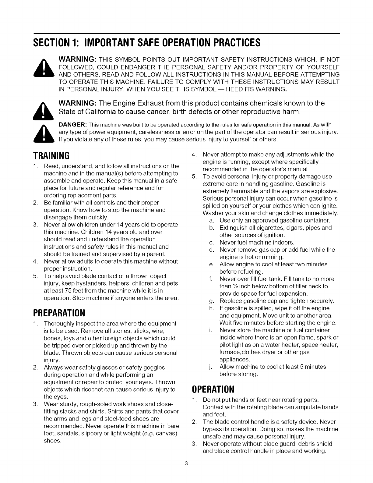
Restrict the use of this power machine to persons who read, understand and follow the warnings
WARNING: YOUR RESPONSIBILITY
and instructions in this manual and on the machine.
• _ =;.4=1=1"_V_'_v,vf±V - - :To)l mP'±_mnilI_ [e] I:] mlp'±wD] =_
==_.4=1=1_IF_,VAv
Figure 1
4
Page 5
SECTION2: ASSEMBLINGYOUREDGER
IMPORTANT:This unit is shipped WITHOUT
GASOLINE or OIL. After setting up the unit, service
engine with gasoline and oil as instructed in the
separate engine manual packed with your unit.
NOTE: Reference to right or left hand side of the edger
is observed from the operating position.
Groundingthe Engine'sSpark Plug
• Disconnect the spark plug wire from the spark plug
and ground against the engine.
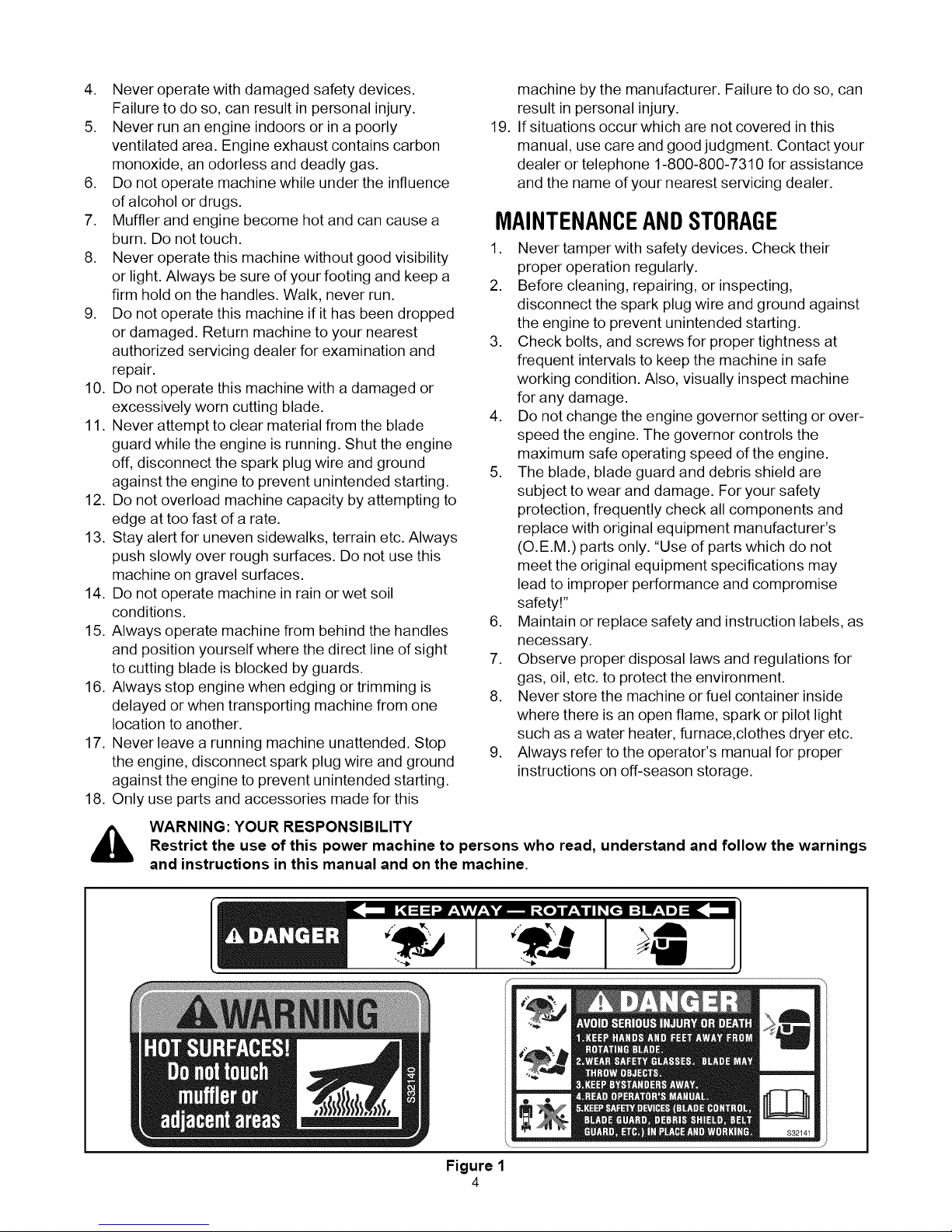
Positioning the EdgerHandles
• Remove and discard any packaging cardboard that
may be present between the upper handle and the
lower handle.
• Depress the blade control bail at the top of the
upper handle and pivot the upper handle upward
until it snaps into place.
• Tighten the wing knobs which are located on both
the left and right sides of the handle. See Figure 2.
Wing Knobs Handle
Rope Guide
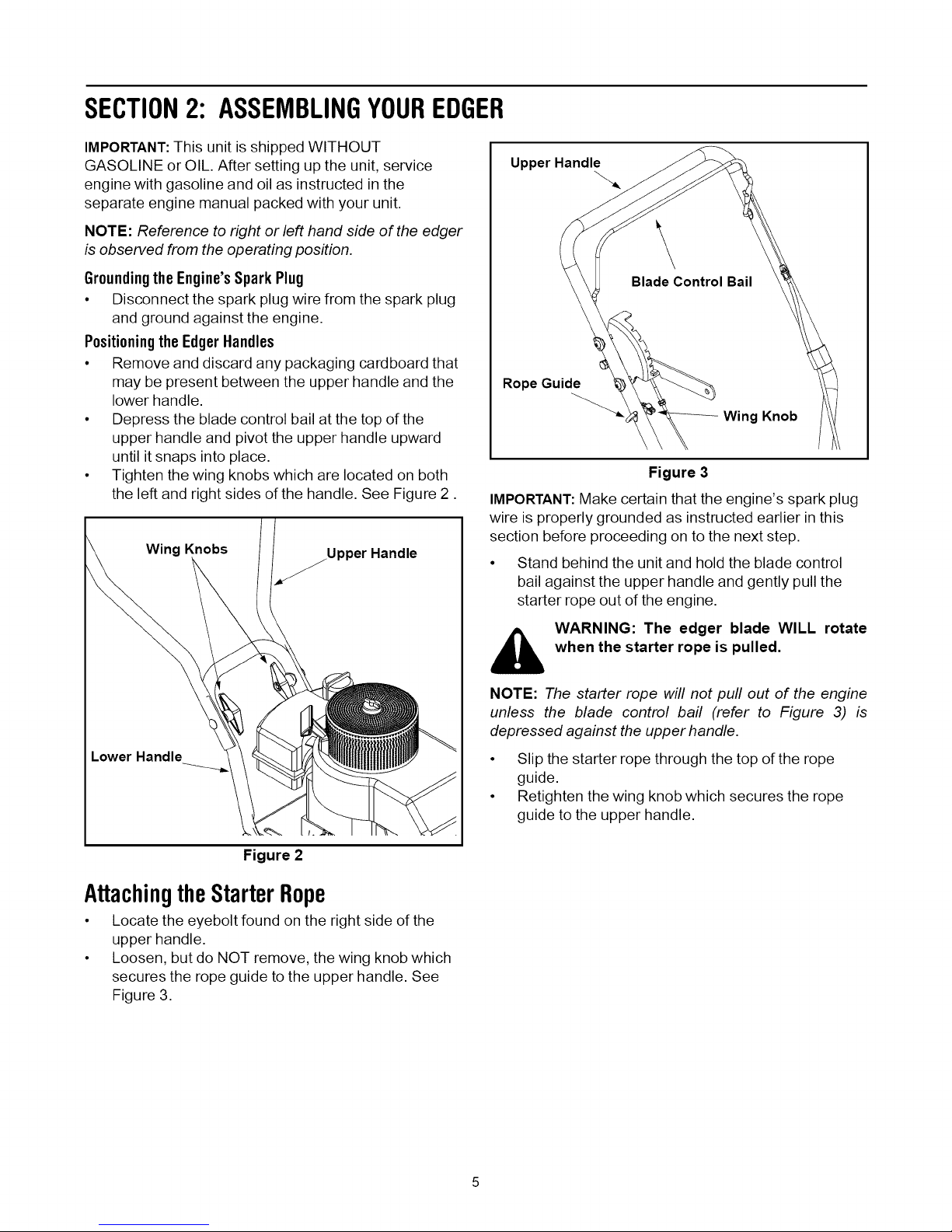
IMPORTANT:Make certain that the engine's spark plug
wire is properly grounded as instructed earlier in this
section before proceeding on to the next step.
• Stand behind the unit and hold the blade control
Upper Handle
\
BladeControl Bail
Wing Knob
Figure 3
bail against the upper handle and gently pull the
starter rope out of the engine.
Lower Handle
Figure 2
AttachingtheStarterRope
• Locate the eyebolt found on the right side of the
upper handle.
• Loosen, but do NOT remove, the wing knob which
secures the rope guide to the upper handle. See
Figure 3.
i_ WARNING: The edger blade WILL rotate
NOTE: The starter rope will not pull out of the engine
unless the blade control bail (refer to Figure 3) is
depressed against the upper handle.
• Slip the starter rope through the top of the rope
• Retighten the wing knob which secures the rope
when the starter rope is pulled.
guide.
guide to the upper handle.
Page 6

SECTION3: KNOWTHEEDGER
Control Bail
Blade Depth
Control Lever
(Transport Position Shown)
Rope / Recoil Starter
Bevel Adjustment
Lever(If Equipped)
Curb Height
Adjustment Lever
(If Equipped)
NOTE: Wheel and blade styles vary.
Yours may differ slightly.
Spindle Sheaves Bel
Figure 4
,_ WARNING: Be familiar with all controls
NOTE: Refer to the Engine Manual packed with your
edger for a detailed description of all engine-related
controls and components.
PullRope/ RecoilStarter
The pull rope/recoil starter is used to start the engine.
and their proper operation. Know how to
stop the machine and disengage them
quickly.
Primer
The primer is used to pump gas into the carburetor and
aid in starting the engine. Use it to start a cold engine,
but do not use it to restart a warm engine after a short
shutdown.
NOTE: Refer to the Engine Manual packed with your
edger for a detailed description of all engine-related
controls and components.
BladeControlBail
Located on the upper handle, the blade control bail
must be depressed against the upper handle inorder to
operate the unit. Releasing the blade control stops the
engine and the edger blade. See Figure 4.
BladeDepthControlLever
The blade depth control lever is located on the right
side of the upper handle. It is used to control the depth
of the cut. The further forward the blade depth control
lever is moved, the deeper into the soil the edger blade
will cut. See Figure 4.
BevelAdjustmentLever(ifsoequipped)
The bevel adjustment lever, if so equipped, is located
on the front, left portion of the edger, behind the edger
blade. It is used to vary the angle of the edger blade
between one of three positions for edging/trenching or
beveled edging. See Figure 4.
CurbHeightAdjustmentLever(if so
equipped)
The curb height adjustment lever, if so equipped, is
found on the rear portion of the edger.When placed in
an applicable notch, it aids in stabilizing the edger while
edging grass along a curb. See Figure 4.
IMPORTANT:Become familiar with all the controls
before operating the edger.
SECTION4: OPERATINGTHEEDGER
The operation of any edger can result
in foreign objects being thrown into
the eyes, which can result in severe
eye damage. Always wear safety
glasses or eye shields. We
recommend wide vision safety mask
for over spectacles or standard
safety glasses
,_ WARNING: Do not lower blade if blade is
over concrete, asphalt, rocks or the like. The
blade can strike the supporting surface,
resulting in personal injury or property
damage.
AddingGasolineAndOil
Service the engine with gasoline and oil as instructed in
the Engine Manual packed with your edger. Read
instructions carefully.
6
Page 7
WARNING:Neverfill fueltankindoors,with
enginerunningoruntiltheenginehasbeen
allowedtocoolforat leasttwominutesafter
running.
StartingTheEngine
NOTE: Refer to the Engine Manual packed with your
edger for a detailed description of all engine-related
controls and components.
To start the edger's engine, proceed as follows:
• Attach the spark plug wire to the spark plug. Make
certain the metal cap on the end of the spark plug
wire is fastened securely over the metal tip on the
spark plug.
• Move the blade depth control lever back to the
START position in the adjacent (top) notch.
• Depress the primer bulb three times, pausing two to
three seconds between each push. In cold weather
(below 50°F/19°C), it may be necessary to depress
the primer bulb four or five times.
IMPORTANT:Using the primer to restart a warm engine
after a short shutdown is usually not necessary. Doing
so may result in a flooded engine.
• Standing behind the unit, depress the blade control
bail and hold it against the upper handle with your
left hand.
WARNING: This control mechanism is a
i_ safety device. Never attempt to bypass its
operation.
• With your right hand, grasp the recoil starter handle
and slowly pull the rope outward until engine
reaches the start of its compression cycle (the rope
will pull slightly harder at this point).
• After slowly allowing the rope to recoil, pull the rope
with a rapid, continuous, full arm stroke. Keep a firm
grip on starter handle throughout the entire stroke.
• Allow the starter handle to slowly return to the
eyebolt.
NOTE: If the engine fails to start after three puffs,
depress the primer an additional two times before
pulling the starter rope again.
To begin edging, proceed as follows:
• Move the blade depth control lever to the left and
place it into any of the five lower notches. The
further forward the blade depth control lever is
moved, the deeper or lower the blade will cut into
the ground.
IMPORTANT:For best results, proceed slowly along the
path being edged, slowly moving the edger back and
forth through the cutting area.
StoppingTheEngine
To stop the edger's engine, proceed as follows:
• Release the blade control handle.
IMPORTANT:Make certain that the engine's spark plug
wire is properly grounded as instructed in SECTION 2:
Assembling The Edger before storing the edger for its
next use.
SECTION5: MAKINGADJUSTMENTS
BevelAdjustment(modelssoequipped)
NOTE: Edger features vary by model. All edger models
do NOT come equipped for blade tilt adjustment nor is
there a blade tilt kit available to modify your edger if it
was not purchased equipped to do so.
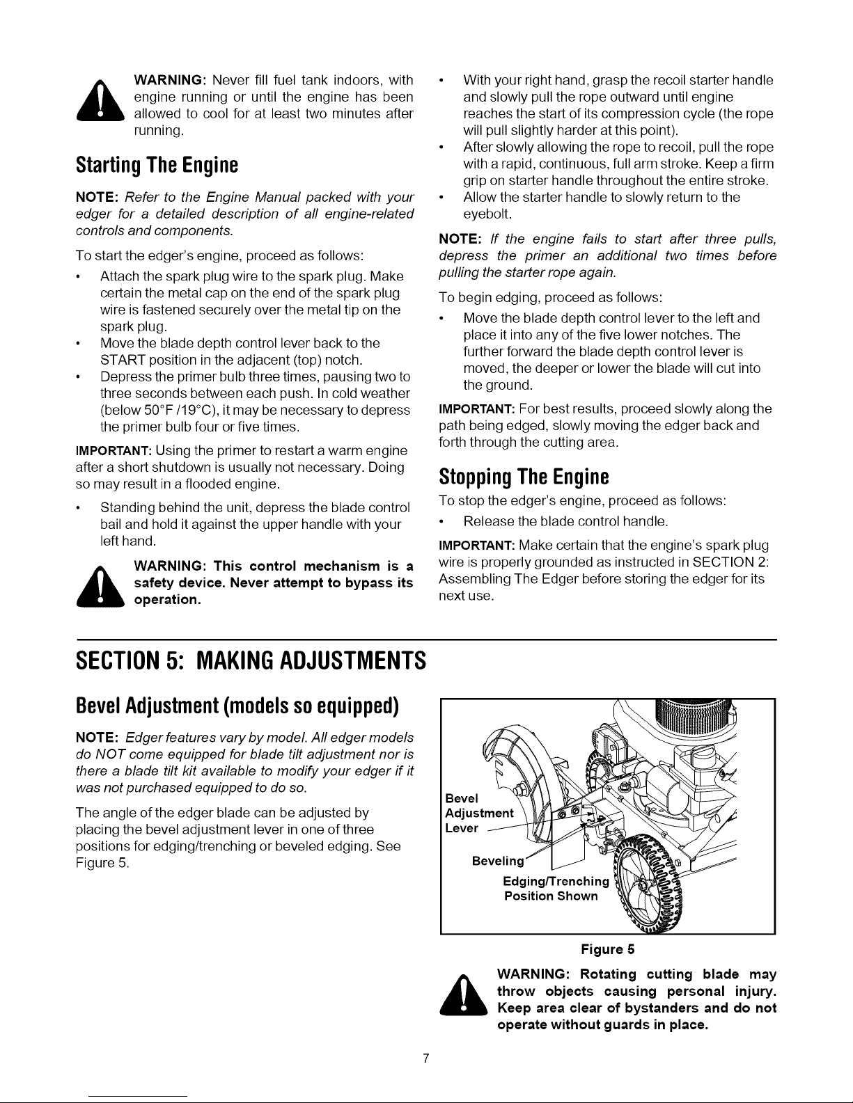
The angle of the edger blade can be adjusted by
placing the bevel adjustment lever in one of three
positions for edging/trenching or beveled edging. See
Figure 5.
Bevel
Adjustment
Lever
Bevelin
Edging/Trenching
Position Shown
Figure 5
_ WARNING: Rotating cutting blade may
throw objects causing personal injury.
Keep area clear of bystanders and do not
operate without guards in place.
Page 8
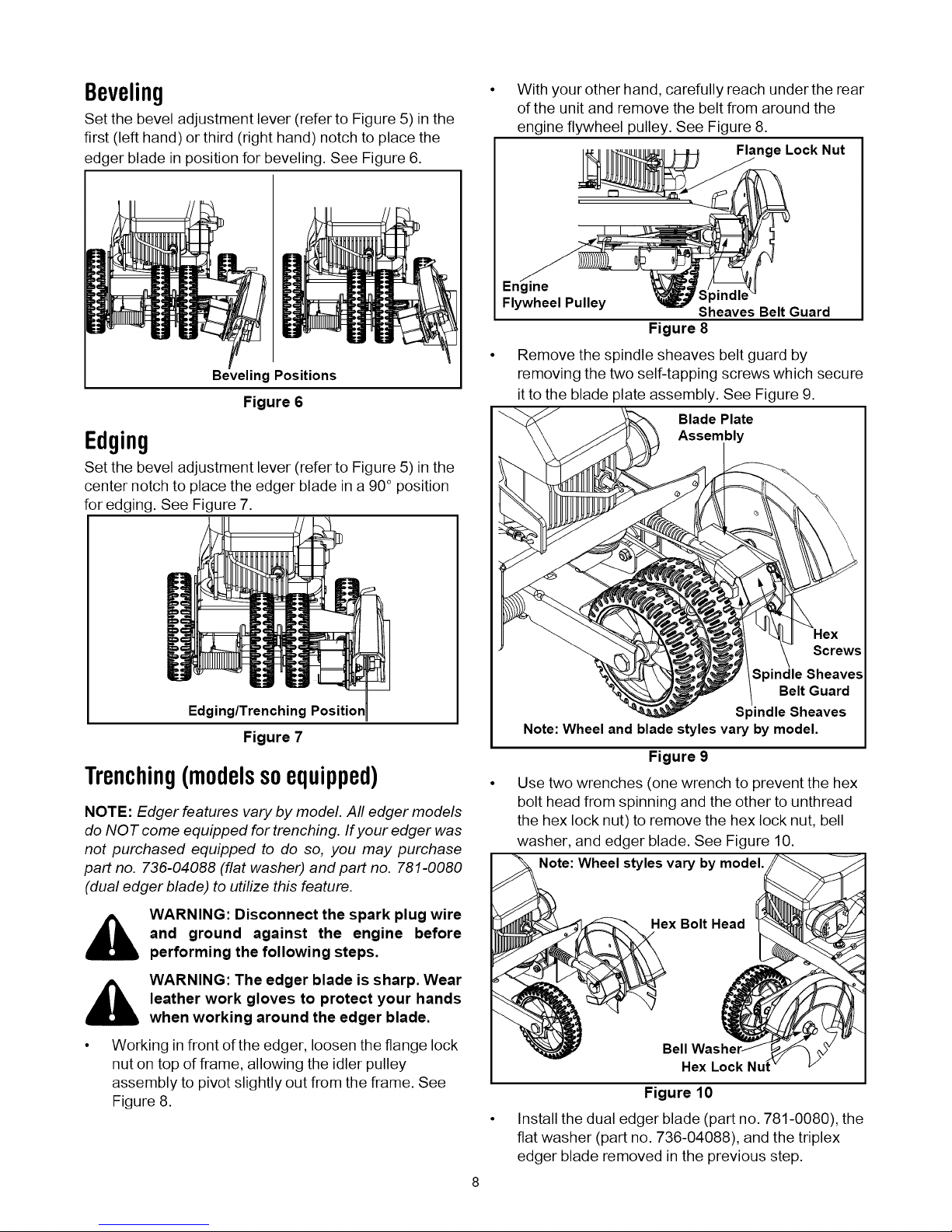
Beveling
Set the bevel adjustment lever (refer to Figure 5) in the
first (left hand) or third (right hand) notch to place the
edger blade in position for beveling. See Figure 6.
Beveling Positions
Figure 6
Edging
Set the bevel adjustment lever (refer to Figure 5) in the
center notch to place the edger blade in a 90° position
for edging. See Figure 7.
With your other hand, carefully reach under the rear
of the unit and remove the belt from around the
engine flywheel pulley. See Figure 8.
Flange Lock Nut
Engine
Flywheel Pulley Sheaves Belt Guard
Figure 8
Remove the spindle sheaves belt guard by
removing the two self-tapping screws which secure
itto the blade plate assembly. See Figure 9.
Blade Plate
Assembly
Edging/Trenching Position
Figure 7
Trenching(modelssoequipped)
NOTE: Edger features vary by model. All edger models
do NOT come equipped for trenching. If your edger was
not purchased equipped to do so, you may purchase
part no. 736-04088 (flat washer) and part no. 781-0080
(dual edger blade) to utilize this feature.
_ WARNING: Disconnect the spark plug wire
_ WARNING: The edger blade is sharp. Wear
and ground against the engine before
performing the following steps.
leather work gloves to protect your hands
when working around the edger blade.
Working in front of the edger, loosen the flange lock
nut on top of frame, allowing the idler pulley
assembly to pivot slightly out from the frame. See
Figure 8.
Hex
Screws
Spindle Sheaves
Belt Guard
Spindle Sheaves
Note: Wheel and blade styles vary by model.
Figure 9
Use two wrenches (one wrench to prevent the hex
bolt head from spinning and the other to unthread
the hex lock nut) to remove the hex lock nut, bell
washer, and edger blade. See Figure 10.
Note: Wheel styles vary bymodel.
Hex Bolt Head
Bell
Hex Lock
Figure 10
Install the dual edger blade (part no. 781-0080), the
flat washer (part no. 736-04088), and the triplex
edger blade removed in the previous step.
Page 9

• Securewiththebellwasherandthehexlocknut
removedearlier.SeeFigure11.
Bell Washer
Edger /
Flat
Triplex Nut
Figure 11
IMPORTANT:Use a torque wrench to tighten the hex
lock nut to between 37 foot-lbs, and 50 foot-lbs.
Reinstall the spindle belt guard with the self tapping
screws removed earlier.
Carefully place the drive belt back onto the engine
flywheel pulley, and retighten the flange lock nut on
the top of the frame.
IMPORTANT:Make certain that the drive belt is seated
correctly on the blade spindle and that it is riding
smoothly on the spindle sheaves and is not pinched
between them. Repeat the first three steps if the belt is
pinched.
Set the bevel adjustment lever (refer to Figure 5) in
the center notch to place the edger blade in a 90°
position (see Figure 7) and place the blade depth
control lever in the lowest position.
IMPORTANT:For best results, proceed slowly along the
path being trenched, slowly moving the edger back and
forth through the cutting area.
there a curb wheel kit available to modify your edger flit
was not purchased equipped to do so.
On models so equipped, the right, rear wheel of the
edger can be lowered into one of five positions to ease
the task of edging along a curb.
To adjust the height of the curb wheel, proceed as
follows:
• Lower the right, rear wheel by moving the curb
height adjustment lever slightly to the left. See
Figure 12.
Curb Height
Adjl
Normal
Figure 12
• Pivot the right, rear wheel into an applicable
position in relation to the height of the curb to be
edged along.
• Release the curb height adjustment lever to lock
the wheel in position. See Figure 13.
NOTE: Utilizing this feature will enable you to create a
wider cutting path for such things as laying wire for
landscape lighting or invisible fences.
EdgingAlongACurb(modelsso
equipped)
NOTE: Edger features vary by model. All edger models
do NOT come equipped to edge along a curb nor is
SECTION6: MAINTAINING& SERVICINGTHEEDGER
_ WARNING: Disconnect the spark plug wire
and ground against the engine before
performing any adjustment, repairs or
maintenance.
ght Adjustment Lever
Figure 13
Lubrication
Engine
Refer to the Engine Manual packed with your edger for
a detailed description of all engine-related service
specifications.
Page 10
Wheels
Lubricate the wheels and bearings at least once a
season with a light oil. Also if the wheels are removed
for any reason, lubricate the surface of the axle bolt and
the inner surface of the wheel with light oil.
PivotPoints
Lubricate the pivot points on the blade control bail,
blade depth control lever, and if applicable, the blade
adjustment lever, and curb height adjustment lever with
light oil at least once a season.
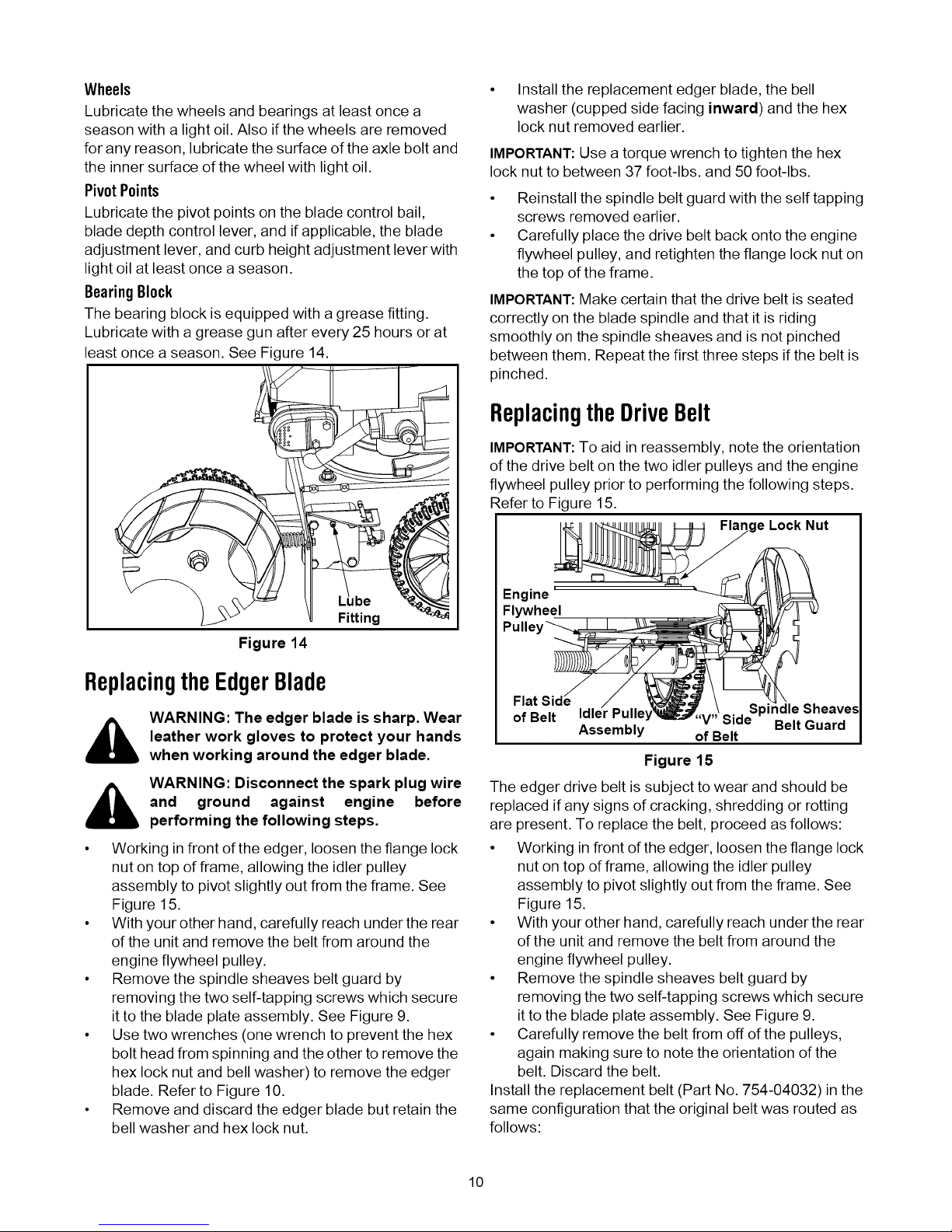
BearingBlock
The bearing block is equipped with a grease fitting.
Lubricate with a grease gun after every 25 hours or at
least once a season. See Figure 14.
• Install the replacement edger blade, the bell
washer (cupped side facing inward) and the hex
lock nut removed earlier.
IMPORTANT:Use a torque wrench to tighten the hex
lock nut to between 37 foot-lbs, and 50 foot-lbs.
Reinstall the spindle belt guard with the self tapping
screws removed earlier.
Carefully place the drive belt back onto the engine
flywheel pulley, and retighten the flange lock nut on
the top of the frame.
IMPORTANT:Make certain that the drive belt is seated
correctly on the blade spindle and that it is riding
smoothly on the spindle sheaves and is not pinched
between them. Repeat the first three steps if the belt is
pinched.
ReplacingtheDriveBelt
IMPORTANT:To aid in reassembly, note the orientation
of the drive belt on the two idler pulleys and the engine
flywheel pulley prior to performing the following steps.
Refer to Figure 15.
e Lock Nut
Fitting
Figure 14
ReplacingtheEdgerBlade
_ WARNING: The edger blade is sharp. Wear
_ WARNING: Disconnect the spark plug wire
• Working in front of the edger, loosen the flange lock
• With your other hand, carefully reach under the rear
• Remove the spindle sheaves belt guard by
• Use two wrenches (one wrench to prevent the hex
• Remove and discard the edger blade but retain the
leather work gloves to protect your hands
when working around the edger blade.
and ground against engine before
performing the following steps.
nut on top of frame, allowing the idler pulley
assembly to pivot slightly out from the frame. See
Figure 15.
of the unit and remove the belt from around the
engine flywheel pulley.
removing the two self-tapping screws which secure
it to the blade plate assembly. See Figure 9.
bolt head from spinning and the other to remove the
hex lock nut and bell washer) to remove the edger
blade. Refer to Figure 10.
bell washer and hex lock nut.
Engine '
Flywheel
Flat idle Sheaves
of Belt V" Side Belt Guard
The edger drive belt is subject to wear and should be
replaced if any signs of cracking, shredding or rotting
are present. To replace the belt, proceed as follows:
• Working in front of the edger, loosen the flange lock
nut on top of frame, allowing the idler pulley
assembly to pivot slightly out from the frame. See
Figure 15.
• With your other hand, carefully reach under the rear
of the unit and remove the belt from around the
engine flywheel pulley.
• Remove the spindle sheaves belt guard by
removing the two self-tapping screws which secure
itto the blade plate assembly. See Figure 9.
• Carefully remove the belt from off of the pulleys,
again making sure to note the orientation of the
belt. Discard the belt.
Install the replacement belt (Part No. 754-04032)in the
same configuration that the original belt was routed as
follows:
Assembly of Belt
Figure 15
10
Page 11
Working from the front of the edger, place the belt
onto the spindle sheaves, route it back onto the two
idler pulleys, and then place it onto the engine
flywheel pulley.
IMPORTANT:Make certain that the "V" side of the belt is
seated into the top pulley and the flat side of the belt is
seated into the bottom pulley. See Figure 15.
• Reinstall the spindle sheaves belt guard with the
self tapping screws removed earlier.
SECTION7: 0FF-SEASONSTORAGE
• Make certain that the drive belt is on the engine
flywheel pulley and idler pulleys, and retighten the
flange lock nut on the top of the frame.
IMPORTANT:Make certain that the drive belt is seated
correctly and that it is riding smoothly on the spindle
sheaves and is not pinched between them. Repeat the
first three steps if the belt is pinched.
_ ARNING: Never operate the edger without
the spindle sheaves belt guard in place.
Observe the following when preparing the edger for
long-term storage:
• Clean and lubricate unit thoroughly as instructed on
page 9 of this manual.
• Refer to the Engine Manual packed separately with
the edger for engine manufacturers's storage
instructions.
• Coat the edger blade with chassis grease to
prevent rusting and corrosion.
• Store the edger in a dry, clean area. Do not store
next to any corrosive materials, such as lawn
fertilizer.
• Coat the edger, especially any springs and
bearings with a light oil or silicone spray.
IMPORTANT:When storing any type of power
equipment in an poorly ventilated or metal storage
shed, care should be taken to rustproof the equipment.
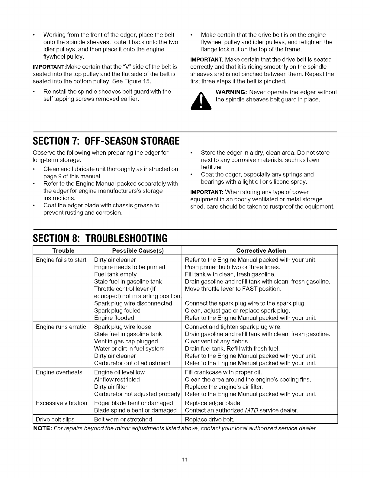
SECTION8: TROUBLESHOOTING
Trouble Corrective Action
Engine fails to start
Throttle control lever (If
Engine runs erratic
Vent in gas cap plugged
Water or dirt in fuel system
Engine overheats
Air flow restricted
Excessive vibration
Drive belt slips Replace drive belt.
NOTE: For repairs beyond the minor adjustments listed above, contact your local authorized service dealer.
Possible Cause(s)
Dirty air cleaner
Engine needs to be primed
Fuel tank empty
Stale fuel in gasoline tank
equipped) not in starting position.
Spark plug wire disconnected
Spark plug fouled
Engine flooded
Spark plug wire loose
Stale fuel in gasoline tank
Dirty air cleaner
Carburetor out of adjustment
Engine oil level low
Dirty air filter
Carburetor not adjusted properly
Edger blade bent or damaged
Blade spindle bent or damaged
Belt worn or stretched
Refer to the Engine Manual packed with your unit.
Push primer bulb two or three times.
Fill tank with clean, fresh gasoline.
Drain gasoline and refill tank with clean, fresh gasoline.
Move throttle lever to FAST position.
Connect the spark plug wire to the spark plug.
Clean, adjust gap or replace spark plug.
Refer to the Engine Manual packed with your unit.
Connect and tighten spark plug wire.
Drain gasoline and refill tank with clean, fresh gasoline.
Clear vent of any debris.
Drain fuel tank. Refill with fresh fuel.
Refer to the Engine Manual packed with your unit.
Refer to the Engine Manual packed with your unit.
Fill crankcase with proper oil.
Clean the area around the engine's cooling fins.
Replace the engine's air filter.
Refer to the Engine Manual packed with your unit.
Replace edger blade.
Contact an authorized MTD service dealer.
11
Page 12

SECTION9: MODEL552 HANDLE
191- 15
20
11
\
5
REF. PART
NO. NO.
1 710-3103
2 710-0449
3 710-1205
4 710-3008
5 710-0606
6 712-3004A
7 720-0279
8 720-0142
9 720-0241
10 732-0369
12
DESCRIPTION
Screw, 5/16-18
Screw, 5/16-18
Eye Bolt
Screw, 5/16-18
Screw
Hex Lock Nut, 5/16-18
Wing Nut
Grip
Wing Knob
Compression Spring
REF.
NO.
11
12
13
14
15
16
17
18
19
2O
l-If so
PART
NO.
736-0451
746-04036
746-04035
747-0976A
749-1225
749-4044
781-0741
781-0742
720-02977
712-3027
equipped
16
DESCRIPTION
Saddle Washer,.320 ID x.93 OD
Wheel Adjustment Cable
Control Cable
Bait Handle
Upper Handle
Lower Handle
Depth Index Bracket
Depth Index Lever
Foam Grip
Hex Flange Nut, 1/4-20
12
Page 13

Model552 Frame
15
2
10
REF.
NO.
1
2
3
4
5
6
7
8
9
10
11
12
13
14
15
PART
NO.
710-0191
710-0599
710-0654A
710-0944
712-0431
731-04168
736-0320
736-0452
736-3052
736-3090
750-04142
756-0313
756-1035A
756-1150A
787-01072
DESCRIPTION
Screw, 3/8-24
Screw, 1/4-20
Screw, 3/8-16
Screw, 3/8-16
Flange Lock Nut, 3/8-16
Debris Guard
Flat Washer, 3/8 ID x 1.37 OD
Belt Washer,.396 x 1.140
Flat Washer,.406 x 1.00
Flat Washer,.260 x.720
Pulley Mount Spacer
Flat Idler Pulley, 1.88 OD
Idler Pulley
Combination Flywheel Pulley
Frame
13
Page 14

Model552SpindleAssembly
18
29
1/
10
19
9
20
23
8
15
11z
14
5
V-BELTS are specially designed to engage and
disengage safely. A substitute (non-OEM) V-Belt
can be dangerous by not disengaging completely.
REF.
NO.
1
2
3
4
5
6
7
8
9
10
11
12
13
14
15
16
PART
NO.
687-02019
710-0395
710-0599
710-1143A
712-3004A
712-3027
712-3056
714-3010
718-04012
731-04158
731-04207
732-04169
732-0188A
736-0119
736-0187
736-0317
DESCRIPTION
Blade Plate Assembly
Hex Screw, 5/16-18
Self-tapping Screw, 1/4-20
Hex Screw, 5/8-18
Hex Lock Nut, 5/16-18
Hex Flange Nut, 1/4-20
Jam Nut, 5/8-18
Cotter Pin
Bearing Cup
Blade Guard
Bearing Block
Compression Spring
Double Torsion Spring
Lock Washer
Flat Washer,.64 ID x 1.24 x.06
Bell Washer,.63 ID x 1.20D
REF. PART
NO. NO.
17 736-3090
18 737-3000
19 738-04025
20 741-0524
21 747-04110
22 736-04088
23 750-04105
24 750-0547
25 754-04032
26 756-0449
27 781-0427
28 781-0748
29 787-01081
30. 736-040881-
31. 781-00801-
1-1fEquipped
DESCRIPTION
Flat Washer,.260 x.72
Lube Fitting, 3/16
Pin, 1/4-20
Bearing,.625 ID x 1.57 OD
Blade Adjustment Rod
Flat Washer
Spacer,.63 x 1.12 x 1.06
Spacer,.632 ID x.875 OD
Belt
Sheave
Spindle Belt Guard
Tri Star Blade
Index Bracket
Flat Washer
Dual Edger Blade
14
Page 15
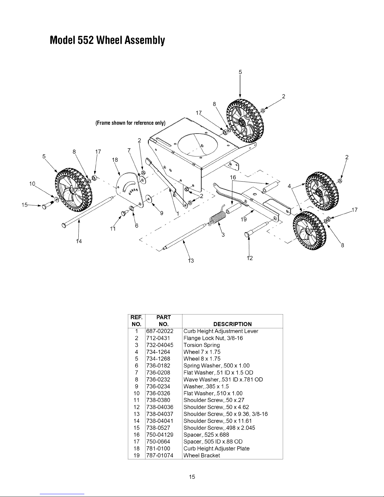
Model552WheelAssembly
(Frameshownfor referenceonly)
2
7
4
REF.
NO.
1
2
3
4
5
6
7
8
9
10
11
12
13
14
15
16
17
18
19
<
687-02022
712-0431
732-04045
734-1264
734-1268
736-0182
736-0208
736-0232
736-0234
736-0326
738-0380
738-04036
738-04037
738-04041
738-0527
750-04129
750-0664
781-0100
787-01074
PART
NO.
DESCRIPTION
Curb Height Adjustment Lever
Flange Lock Nut, 3/8-16
Torsion Spring
Wheel 7 x 1.75
Wheel 8 x 1.75
Spring Washer,.500 x 1.00
Flat Washer,.51 ID x 1.50D
Wave Washer,.531 ID x.781 OD
Washer,.385 x 1.5
Flat Washer,.510 x 1.00
Shoulder Screw,.50 x.27
Shoulder Screw,.50 x 4.62
Shoulder Screw,.50 x 9.36, 3/8-16
Shoulder Screw,.50 x 11.61
Shoulder Screw,.498 x 2.045
Spacer,.525 x.688
Spacer,.505 ID x.88 OD
Curb Height Adjuster Plate
Wheel Bracket
15
Page 16

MANUFACTURER'S LIMITED WARRANTY FOR:
YaRD.MaNTM
®
The limited warranty set forth below is given by MTD LLC with
respect to new merchandise purchased and used in the
United States, its possessions and territories.
"MTD" warrants this product against defects in material and
workmanship for a period of two (2) years commencing on the
date of original purchase and wilt, at its option, repair or
replace, free of charge, any part found to be defective in
materials or workmanship. This limited warranty shall only
apply if this product has been operated and maintained in
accordance with the Operator's Manual furnished with the
product, and has not been subject to misuse, abuse,
commercial use, neglect, accident, improper maintenance,
alteration, vandalism, theft, fire, water, or damage because of
other peril or natural disaster. Damage resulting from the
installation or use of any part, accessory or attachment not
approved by MTD for use with the product(s) covered by this
manual will void your warranty as to any resulting damage.
Normal wear parts are warranted to be free from defects in
material and workmanship for a period of thirty (30) days from
the date of purchase. Normal wear parts include, but not
limited to items such as: batteries, belts, blades, blade
adapters, grass bags, rider deck wheels, seats, snow thrower
skid shoes, shave plates, auger spiral rubber and tires.
HOW TO OBTAIN SERVICE: Warranty service is available,
WITH PROOF OF PURCHASE, through your local authorized
service dealer. To locate the dealer in your area, check your
Yellow Pages, or contact MTD LLC at P.O. Box 361131,
Cleveland, Ohio 44136-0019, or call 1-800-800-7310 or log
on to our Web site at www.mtdproducts.com.
This limited warranty does not provide coverage in the
following cases:
a,
The engine or component parts thereof. These items
may carry a separate manufacturer's warranty. Refer
to applicable manufacturer's warranty for terms and
conditions.
b,
Log splitter pumps, valves, and cylinders have a
separate one year warranty.
C.
Routine maintenance items such as lubricants, filters,
blade sharpening, tune-ups, brake adjustments, clutch
adjustments, deck adjustments, and normal
deterioration of the exterior finish due to use or
exposure.
d,
Service completed by someone other than an
authorized service dealer.
e,
MTD does not extend any warranty for products sold or
exported outside of the United States, its possessions
and territories, except those sold through MTD's
authorized channels of export distribution.
f,
Replacement parts that are not genuine MTD parts.
Transportation charges and service calls.
g.
No implied warranty, including any implied warranty of
merchantability of fitness for a particular purpose,
applies after the applicable period of express written
warranty above as to the parts as identified. No other
express warranty, whether written or oral, except as
mentioned above, given by any person or entity,
including a dealer or retailer, with respect to any product,
shall bind MTD. During the period of the warranty, the
exclusive remedy is repair or replacement of the product
as set forth above.
The provisions as set forth in this warranty provide the
sole and exclusive remedy arising from the sale. MTD
shall not be liable for incidental or consequential loss or
damage including, without limitation, expenses incurred
for substitute or replacement lawn care services or for
rental expenses to temporarily replace awarranted
product.
Some states do not allow the exclusion or limitation of
incidental or consequential damages, or limitations on how
long an implied warranty lasts, so the above exclusions or
limitations may not apply to you.
In no event shall recovery of any kind be greater than the
amount of the purchase price of the product sold. Alteration
of safety features of the product shall void this warranty.
You assume the risk and liability for toss, damage, or injury to
you and your property and/or to others and their property
arising out of the misuse or inability to use the product.
This limited warranty shall not extend to anyone other than the
original purchaser or to the person for whom it was purchased
as a gift.
HOW STATE LAW RELATES TO THIS WARRANTY: This
limited warranty gives you specific legal rights, and you may
also have other rights which vary from state to state.
IMPORTANT:Owner must present Original Proof of
Purchase to obtain warranty coverage.
MTD LLC, P.O.BOX361131CLEVELAND,OHIO44136-0019;Phone:1-800-800-7310
 Loading...