


FOREWORD
This Supplementary Service Manual has been prepared to introduce new service and data for the
YZF-R6 (L) 2000. For complete service information procedures it is necessary to use this Supplementary Service Manual together with the following manual.
YZF-R6 ’99 SERVICE MANUAL: 5EB1-AE1
YZF-R6 (L) 2000
SUPPLEMENTARY
SERVICE MANUAL
1999 by Yamaha Motor Co., Ltd.
First Edition, August 1999
Any reproduction or unauthorized use
without the written permission of
Yamaha Motor Co., Ltd. is expressly
prohibited.

NOTE:
WARNING
CAUTION:
EB001000
NOTICE
This manual was produced by the Y amaha Motor Company , Ltd. primarily for use by Y amaha dealers
and their qualified mechanics. It is not possible to include all the knowledge of a mechanic in one manual, so it is assumed that anyone who uses this book to perform maintenance and repairs on Y amaha
motorcycles has a basic understanding of the mechanical ideas and the procedures of motorcycles
repair.
Repairs attempted by anyone without this knowledge are likely to render the motorcycles unfit for use.
Y amaha Motor Company, Ltd. is continually striving to improve all its models. Modifications and significant changes in specifications or procedures will be forwarded to all authorized Y amaha dealers and
will appear in future editions of this manual where applicable.
Designs and specifications are subject to change without notice.
IMPORTANT INFORMATION
Particularly important information is distinguished in this manual by the following.
The Safety Alert Symbol means ATTENTION! BECOME ALERT! YOUR
SAFETY IS INVOLVED!
Failure to follow WARNING instructions could result in severe injury or death
to
the motorcycle operator, a bystander or a person inspecting or repairing the
motorcycle.
A CAUTION indicates special precautions that must be taken to avoid damage
to the motorcycle.
NOTE: A NOTE provides key information to make procedures easier or clearer.
7
2
1
4
3
8
6
5
YP002000
HOW TO USE THIS MANUAL
This manual is intended as a handy , easy-to-read reference book for the mechanic. Comprehensive
explanations of all installation, removal, disassembly , assembly , repair and inspection procedures are
laid out with the individual steps in sequential order.
1
The manual is divided into chapters. An abbreviation and symbol in the upper right corner of each
page indicate the current chapter. Refer to “SYMBOLS” on the following page.
2
Each chapter is divided into sections. The current section title is shown at the top of each page,
except in Chapter 3 (“Periodic Inspections and Adjustments”), where the sub-section title (-s) appear.
(In Chapter 3, “Periodic Inspections and Adjustments”, the sub-section title appears at the top of each
page, instead of the section title.)
3
Sub-section titles appear in smaller print than the section title.
4
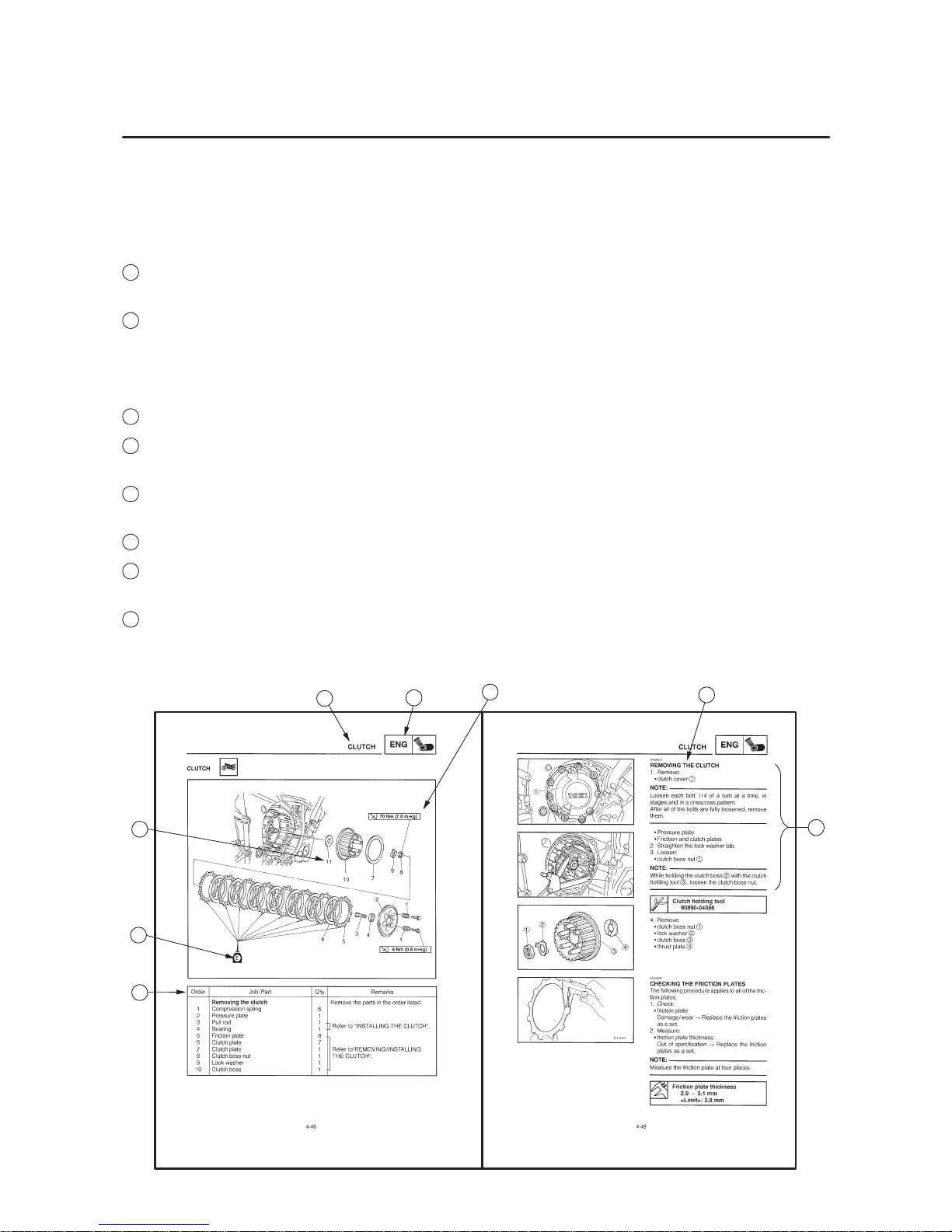
To help identify parts and clarify procedure steps, there are exploded diagrams at the start of each
removal and disassembly section.
5
Numbers are given in the order of the jobs in the exploded diagram. A circled number indicates a
disassembly step.
6
Symbols indicate parts to be lubricated or replaced (see “SYMBOLS”).
7
A job instruction chart accompanies the exploded diagram, providing the order of jobs, names of
parts, notes in jobs, etc.
8
Jobs requiring more information (such as special tools and technical data) are described sequen-
tial0ly .

22
1
3
5
7
9
2
4
8
6
24 25
2321
19 2018
15
1413
11 12
10
GEN
INFO
SPEC
ENG
CARB
ELEC
CHK
ADJ
TRBL
SHTG
16 17
COOL
CHAS
EB003000
SYMBOLS
The following symbols are not relevant to every
vehicle.
Symbols
1
to 9 indicate the subject of each
chapter.
1
General information
2
Specifications
3
Periodic checks and adjustment
4
Engine
5
Cooling system
6
Carburetor(-s)
7
Chassis
8
Electrical system
9
Troubleshooting
Symbols 10 to 17 indicate the following.
10
Serviceable with engine mounted
11
Filling fluid
12
Lubricant
13
Special tool
14
Tightening torque
15
Wear limit, clearance
16
Engine speed
17
Electrical data
Symbols 18 to 23 in the exploded diagrams indicate the types of lubricants and lubrication
points.
18
Apply engine oil
19
Apply gear oil
20
Apply molybdenum disulfide oil
21
Apply wheel bearing grease
22
Apply lightweight lithium-soap base grease
23
Apply molybdenum disulfide grease
Symbols 24 to 25 in the exploded diagrams indicate the following:
24
Apply locking agent (LOCTITE)
25
Use new one

CONTENTS
GENERAL INFORMATION 1. . . . . . . . . . . . . . . . . . . . . . . . . . . . . . . . . . . . . .
SPECIAL TOOLS 1. . . . . . . . . . . . . . . . . . . . . . . . . . . . . . . . . . . . . . . . . . .
SPECIFICA TIONS 2. . . . . . . . . . . . . . . . . . . . . . . . . . . . . . . . . . . . . . . . . . . . .
ENGINE SPECIFICATIONS 2. . . . . . . . . . . . . . . . . . . . . . . . . . . . . . . . . .
ELECTRICAL SPECIFICATIONS 2. . . . . . . . . . . . . . . . . . . . . . . . . . . . .
TIGHTENING TORQUE 3. . . . . . . . . . . . . . . . . . . . . . . . . . . . . . . . . . . . .
CHASSIS TIGHTENING TORQUE 3. . . . . . . . . . . . . . . . . . . . . . . . .
CABLE ROUTING 4. . . . . . . . . . . . . . . . . . . . . . . . . . . . . . . . . . . . . . . . . .
PERIODIC CHECKS AND ADJUSTMENT 12. . . . . . . . . . . . . . . . . . . . . . . .
CHASSIS 12. . . . . . . . . . . . . . . . . . . . . . . . . . . . . . . . . . . . . . . . . . . . . . . . . .
ADJUSTING THE CLUTCH CABLE FREE PLAY 12. . . . . . . . . . . .
OVERHAULING THE ENGINE 13. . . . . . . . . . . . . . . . . . . . . . . . . . . . . . . . . .
ENGINE 13. . . . . . . . . . . . . . . . . . . . . . . . . . . . . . . . . . . . . . . . . . . . . . . . . . .
DRIVE SPROCKET 13. . . . . . . . . . . . . . . . . . . . . . . . . . . . . . . . . . . . . .
ENGINE 14. . . . . . . . . . . . . . . . . . . . . . . . . . . . . . . . . . . . . . . . . . . . . . . . . . .
INSTALLING THE ENGINE 15. . . . . . . . . . . . . . . . . . . . . . . . . . . . . . .
PICKUP COIL AND PICKUP ROTOR 16. . . . . . . . . . . . . . . . . . . . . . . . . .
INSTALLING THE PICKUP COIL ROTOR 16. . . . . . . . . . . . . . . . . .
CHASSIS 18. . . . . . . . . . . . . . . . . . . . . . . . . . . . . . . . . . . . . . . . . . . . . . . . . . . . .
REAR SHOCK ABSORBER ASSEMBL Y 18. . . . . . . . . . . . . . . . . . . . . . .
REMOVING THE REAR SHOCK ABSORBER ASSEMBLY 19. . .
SWINGARM AND DRIVE CHAIN 20. . . . . . . . . . . . . . . . . . . . . . . . . . . . .
INSTALLING THE SWINGARM 22. . . . . . . . . . . . . . . . . . . . . . . . . . . .
YZF-R6 (L) 2000 WIRING DIAGRAM

–1–
SPECIAL TOOLS
GEN
INFO
EB104000
SPECIAL TOOLS
The following special tools are necessary for complete and accurate tune-up and assembly.
Use only the appropriate special tools as this will help prevent damage caused by the use of inappropriate tools or improvised techniques.
When placing an order, refer to the list provided below to avoid any mistakes.
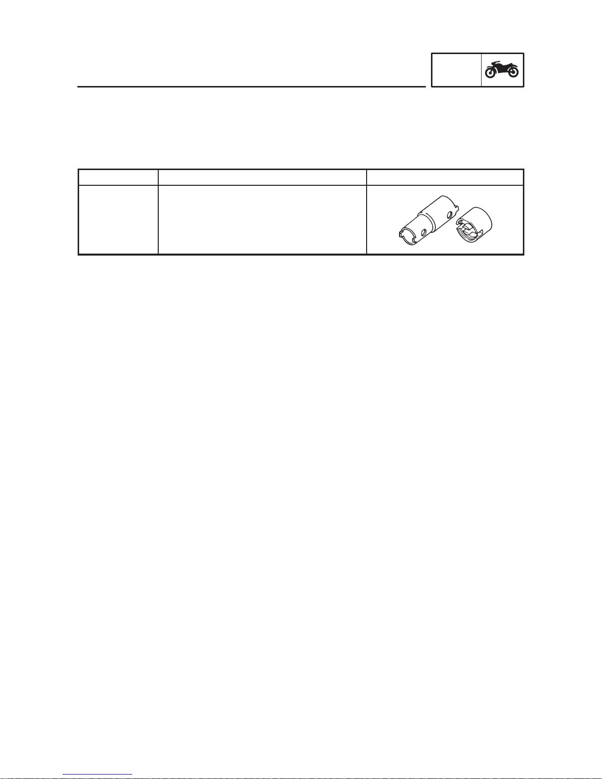
Tool No.
Tool name/Function Illustration
Pivot shaft
wrench
90890-01471
Adapter
90890-01476
Pivot shaft wrench
Adapter
This tool is used to loosen or tighten the pivot
adjust bolt and engine mount adjust bolt.
–2–
ENGINE SPECIFICATIONS/ELECTRICAL SPECIFICATIONS
SPEC
ENGINE SPECIFICATIONS
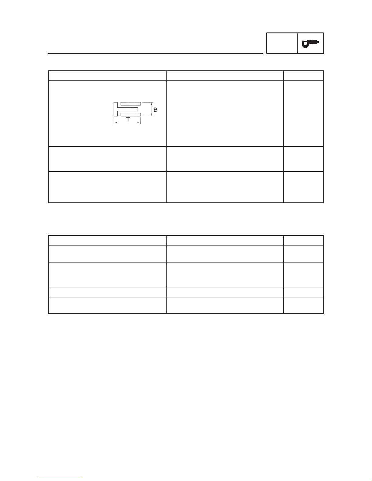
Item Standard Limit
Pistons
Oil ring
Dimensions (B T)
End gap (installed)
1.5 2.0 mm
0.10 0.35 mm
Crankshaft
Crankshaft-journal-to-crankshaftjournal-bearing clearance
0.028 0.052 mm
Carburetors
ID mark
Jet needle
Pilot screw turns out
5EB1
#1, 4: N7RA #2, 3: N7SA
1-1/2 2
ELECTRICAL SPECIFICATIONS
Item Standard Limit
Ignition system
Ignition timing
10 BTDC at 1300 r/min
Ignition coils
Primary coil resistance
Secondary coil resistance
0.204 0.276 Ω
8.5 11.5 Ω
Oil level switch model (manufacturer) 5EB (DENSO)
Fuel pump relay model (manufacturer)
Resistance
G8R-30Y-M (OMRON)
162 198 Ω
 Loading...