

Manuals by Motomatrix / www.motomatrix.co.uk / The Solution For Lost Motorcycle Coded Keys
email: info@motomatrix.co.uk

Manuals by Motomatrix / www.motomatrix.co.uk / The Solution For Lost Motorcycle Coded Keys
email: info@motomatrix.co.uk
FOREWORD
This Supplementary Service Manual has been prepared to introduce new service and data for the
YZF-R6 (S) 2004. For complete service information procedures it is necessary to use this Supplementary Service Manual together with the following manual.
YZF-R6 (R) 2003 SERVICE MANUAL: 5SL1-AE1
YZF-R6 (S) 2004
SUPPLEMENTARY
SERVICE MANUAL
E2003 by Yamaha Motor Co., Ltd.
First Edition, September 2003
All rights reserved.
Any reproduction or unauthorized use
without the written permission of
Yamaha Motor Co., Ltd.
is expressly prohibited.
Manuals by Motomatrix / www.motomatrix.co.uk / The Solution For Lost Motorcycle Coded Keys
email: info@motomatrix.co.uk
NOTE:
WARNING
CAUTION:
EAS00002
NOTICE
This manual was produced by the Yamaha Motor Company, Ltd. primarily for use by Yamaha dealers
and their qualified mechanics. It is not possible to include all the knowledge of a mechanic in one manual. Therefore, anyone who uses this book to perform maintenance and repairs on Yamaha vehicles
should have a basic understanding of mechanics and the techniques to repair these types of vehicles.
Repair and maintenance work attempted by anyone without this knowledge is likely to render the vehicle unsafe and unfit for use.
Yamaha Motor Company, Ltd. is continually striving to improve all of its models. Modifications and significant changes in specifications or procedures will be forwarded to all authorized Yamaha dealers
and will appear in future editions of this manual where applicable.
Designs and specifications are subject to change without notice.
EAS00004
IMPORTANT MANUAL INFORMATION
Particularly important information is distinguished in this manual by the following.
The Safety Alert Symbol means ATTENTION! BECOME ALERT! YOUR
SAFETY IS INVOLVED!
Failure to follow WARNING instructions could result in severe injury or death
to
the motorcycle operator, a bystander or a person checking or repairing the motorcycle.
A CAUTION indicates special precautions that must be taken to avoid damage
to the motorcycle.
NOTE: A NOTE provides key information to make procedures easier or clearer.
Manuals by Motomatrix / www.motomatrix.co.uk / The Solution For Lost Motorcycle Coded Keys
email: info@motomatrix.co.uk

12
4
8
3
5
6
7
EAS00007
HOW TO USE THIS MANUAL
This manual is intended as a handy, easy-to-read reference book for the mechanic. Comprehensive
explanations of all installation, removal, disassembly, assembly, repair and check procedures are laid
out with the individual steps in sequential order.
1
The manual is divided into chapters. An abbreviation and symbol in the upper right corner of each
page indicate the current chapter.
Refer to “SYMBOLS”.
2
Each chapter is divided into sections. The current section title is shown at the top of each page,
except in Chapter 3 (“PERIODIC CHECKS AND ADJUSTMENTS”), where the sub-section title(s) appears.
3
Sub-section titles appear in smaller print than the section title.
4
To help identify parts and clarify procedure steps, there are exploded diagrams at the start of each
removal and disassembly section.
5
Numbers are given in the order of the jobs in the exploded diagram. A circled number indicates a
disassembly step.
6
Symbols indicate parts to be lubricated or replaced.
Refer to “SYMBOLS”.
7
A job instruction chart accompanies the exploded diagram, providing the order of jobs, names of
parts, notes in jobs, etc.
8
Jobs requiring more information (such as special tools and technical data) are described sequentially.
Manuals by Motomatrix / www.motomatrix.co.uk / The Solution For Lost Motorcycle Coded Keys
email: info@motomatrix.co.uk

22
1
3
5
7
9
2
4
8
6
24 25
2321
19 2018
16 1715
1413
11 12
10
GEN
INFO
SPEC
ENG
FI ELEC
COOL
CHK
ADJ
TRBL
SHTG
CHAS
EAS00008
SYMBOLS
The following symbols are not relevant to every
vehicle.
Symbols
1
to 9 indicate the subject of each
chapter.
1
General information
2
Specifications
3
Periodic checks and adjustments
4
Chassis
5
Engine
6
Cooling system
7
Fuel injection system
8
Electrical system
9
Troubleshooting
Symbols 10 to 17 indicate the following.
10
Serviceable with engine mounted
11
Filling fluid
12
Lubricant
13
Special tool
14
Tightening torque
15
Wear limit, clearance
16
Engine speed
17
Electrical data
Symbols 18 to 23 in the exploded diagrams indicate the types of lubricants and lubrication
points.
18
Engine oil
19
Gear oil
20
Molybdenum-disulfide oil
21
Wheel-bearing grease
22
Lithium-soap- based grease
23
Molybdenum-disulfide grease
Symbols 24 to 25 in the exploded diagrams indicate the following.
24
Apply locking agent (LOCTITE)
25
Replace the part
Manuals by Motomatrix / www.motomatrix.co.uk / The Solution For Lost Motorcycle Coded Keys
email: info@motomatrix.co.uk

CONTENTS
SPECIFICATIONS
GENERAL SPECIFICATIONS 1. . . . . . . . . . . . . . . . . . . . . . . . . . . . . . . . . .
ENGINE SPECIFICATIONS 1. . . . . . . . . . . . . . . . . . . . . . . . . . . . . . . . . . . .
CHASSIS SPECIFICATIONS 1. . . . . . . . . . . . . . . . . . . . . . . . . . . . . . . . . . .
ELECTRICAL SPECIFICATIONS 1. . . . . . . . . . . . . . . . . . . . . . . . . . . . . . .
TIGHTENING TORQUES 2. . . . . . . . . . . . . . . . . . . . . . . . . . . . . . . . . . . . . .
ENGINE TIGHTENING TORQUES 2. . . . . . . . . . . . . . . . . . . . . . . . . . .
CABLE ROUTING 3. . . . . . . . . . . . . . . . . . . . . . . . . . . . . . . . . . . . . . . . . . . .
PERIODIC CHECKS AND ADJUSTMENTS
FUEL TANK 14. . . . . . . . . . . . . . . . . . . . . . . . . . . . . . . . . . . . . . . . . . . . . . . . . .
INSTALLING THE FUEL PUMP 15. . . . . . . . . . . . . . . . . . . . . . . . . . . . . .
FUEL INJECTION SYSTEM
AIR INDUCTION SYSTEM 16. . . . . . . . . . . . . . . . . . . . . . . . . . . . . . . . . . . . .
AIR INDUCTION SYSTEM DIAGRAMS 16. . . . . . . . . . . . . . . . . . . . . . .
ELECTRICAL
ELECTRICAL COMPONENTS 17. . . . . . . . . . . . . . . . . . . . . . . . . . . . . . . . . .
IGNITION SYSTEM 18. . . . . . . . . . . . . . . . . . . . . . . . . . . . . . . . . . . . . . . . . . .
CIRCUIT DIAGRAM 18. . . . . . . . . . . . . . . . . . . . . . . . . . . . . . . . . . . . . . . .
TROUBLESHOOTING 19. . . . . . . . . . . . . . . . . . . . . . . . . . . . . . . . . . . . . .
LIGHTING SYSTEM 24. . . . . . . . . . . . . . . . . . . . . . . . . . . . . . . . . . . . . . . . . . .
CIRCUIT DIAGRAM 24. . . . . . . . . . . . . . . . . . . . . . . . . . . . . . . . . . . . . . . .
CHECKING THE LIGHTING SYSTEM 26. . . . . . . . . . . . . . . . . . . . . . . .
YZF-R6 (S) 2004 WIRING DIAGRAM
Manuals by Motomatrix / www.motomatrix.co.uk / The Solution For Lost Motorcycle Coded Keys
email: info@motomatrix.co.uk

Manuals by Motomatrix / www.motomatrix.co.uk / The Solution For Lost Motorcycle Coded Keys
email: info@motomatrix.co.uk

–1–
GENERAL SPECIFICATIONS
SPEC
SPECIFICATIONS
GENERAL SPECIFICATIONS
Item Standard Limit
Model code 5SLB (EUR), 5SLC (F), 5SLG/5SLL (AUS) SSS
ENGINE SPECIFICATIONS
Item Standard Limit
Throttle bodies
ID mark
Throttle valve size
5SL1 00 (5SLB/5SLG / 5SLL),
5SL2 20 (5SLC)
#100
SSS
SSS
CHASSIS SPECIFICATIONS
Item Standard Limit
Front tire
Model (manufacturer)
Pilot SPORT N (MICHELIN)
D208 FJ (DUNLOP)
SSS
Rear tire
Model (manufacturer)
Pilot SPORT B (MICHELIN)
D208 AJ (DUNLOP)
SSS
ELECTRICAL SPECIFICATIONS
Item Standard Limit
Ignition system
CDI unit model (manufacturer)
F8T814 (MITSUBISHI)
(5SLB/5SLG / 5SLL)
F8T815 (MITSUBISHI) (5SLC)
SSS
SSS
Ignition coils
Model (manufacturer)
Primary coil resistance
Secondary coil resistance
F6T549 (MITSUBISHI)
0.24 X 0.32 Ω at 20_C (68_F)
5.0 X 6.8 kΩ at 20_C (68_F)
SSS
SSS
SSS
Manuals by Motomatrix / www.motomatrix.co.uk / The Solution For Lost Motorcycle Coded Keys
email: info@motomatrix.co.uk
–2–
TIGHTENING TORQUES
SPEC
TIGHTENING TORQUES
ENGINE TIGHTENING TORQUES
Thread
’
Tightening torque
Item
Fastener
size
Qty
Nm mSkg ftSlb
Remarks
Oil cooler
Cylinder identification sensor
Bolt
Bolt
M20
M6
1
1
63
6.0
6.3
0.6
46
4.3
Yamaha bond
No.1215
Manuals by Motomatrix / www.motomatrix.co.uk / The Solution For Lost Motorcycle Coded Keys
email: info@motomatrix.co.uk
–3–
CABLE ROUTING
SPEC
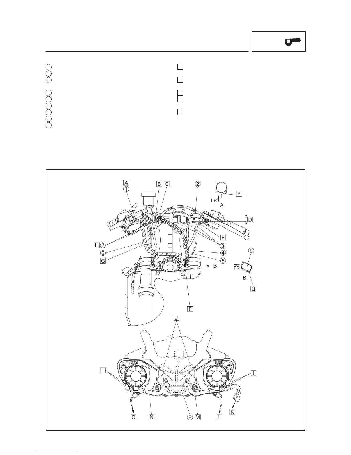
A Pass the right handlebar switch lead inside the front
brake hoses and over the throttle cables.
B Install the throttle cables to the hook so that the pull-
ing side of the throttle cables is routed downward.
C Pass the clutch cable through the guide.
D Plastic locking tie shall be positioned at 10 mm
(0.39 in.) below from the upper bracket.
E Clamp the left handlebar switch lead to the front fork
with the plastic locking tie and cut the tip of the tie.
Clamp it to the protector section.
1 Right handlebar switch lead
2 Clutch cable
3 Immobilizer unit lead, main switch lead and left han-
dlebar switch lead
4 Throttle cable (return side)
5 Throttle cable (pull side)
6 Front brake hoses
7 Throttle cables
8 Joint
9 Under bracket
CABLE ROUTING
Manuals by Motomatrix / www.motomatrix.co.uk / The Solution For Lost Motorcycle Coded Keys
email: info@motomatrix.co.uk

–4–
I Set in the coupler between the head light’s hollow
section and the duct.
J Install the relay to the rib of the head light.
(Location for the left and right relays is alternative.)
K To the wire harness
L To the front turn signal light (right)
M Set the sub wire harness in the joint.
N Do not catch the sub wire harness when the duct is
assembled.
O To the front turn signal light (left)
P Point the tip of the plastic locking tie to the front side
of the vehicle. Cut the tip leaving 2 X 10 mm (0.08
X 0.39 in).
Q Point the tip of the plastic locking tie under the under
bracket and rear side of the vehicle. Cut the tip leav-
ing 2 X 10 mm (0.08 X 0.39 in).
CABLE ROUTING
SPEC
F Pass the horn lead by the outside of the throttle
cable and clamp it to the forefront of upper face of
the under bracket. Next, route it under the front
brake hose and clamp it to the pawl of the under
cover.
G Clamp it at the position of 40 (1.57 in.) to 60 mm
(2.36 in.) from the upper face of the under bracket
with the plastic locking tie. Cut the surplus part of the
clamp tip leaving 2 (0.08 in.) to 4 mm (0.16 in.). Point
the tip of the clamp to the outside of vehicle.
H Pass the throttle cables inside the front brake
hoses.
Manuals by Motomatrix / www.motomatrix.co.uk / The Solution For Lost Motorcycle Coded Keys
email: info@motomatrix.co.uk

–5–
CABLE ROUTING
SPEC
1 Throttle stop screw
2 Coolant reservoir tank hose
3 Pickup coil lead
4 Rear brake light switch lead
5 Coolant hose
6 Clutch cable
7 Coolant hose protector
8 Hose clamp assembly
9 Hose clamp
A Pass the rear brake light switch lead outside of rear
engine mount bolt.
B Pass the ignition coil lead outside of the radiator
hose.
C Pass the coolant reservoir tank hose under the
frame and right side of the throttle body.
D Pass the clutch cable inside of the coolant reservoir
tank hose and radiator return hoses.
E Assemble as “ ” shown below when clamping.
F Pass the pickup coil lead over the throttle stop
cable.
G Tip of the plastic locking tie shall be pointed to the
inner side at the rear part of the vehicle.
H The punch mark starting point should be lower than
the clamp’s top end.
However, the aiming position of the punch mark
starting point should be 5 mm (0.20 in) below the
clamp’s bottom end.
I Pass the clutch cable inside of the radiator hose.
J Clamp the clutch cable so that it is positioned in this
range.
K Put and apply the hose clamp to it.
a
Manuals by Motomatrix / www.motomatrix.co.uk / The Solution For Lost Motorcycle Coded Keys
email: info@motomatrix.co.uk
 Loading...