

Page 1

q
Read this manual carefully before operating this vehicle.
OWNER’S MANUAL
YZF-R1
YZF-R1M
2CR-28199-E0
0
Page 2
Read this manual carefully before operating this vehicle. This manual should stay with this vehicle if it is sold.
Q
YAMAHA MOTOR ELECTRONICS CO., LTD.
1450-6, Mori, Mori-machi, Shuchi-gun, Shizuoka-ken, 437-0292 Japan
DECLARATION of CONFORMITY
We
Company: YAMAHA MOTOR ELECTRONICS CO., LTD.
Address: 1450-6, Mori, Mori-Machi, Shuchi-gun, Shizuoka-Ken, 437-0292 Japan
Hereby declare that the product:
Kind of equipment: IMMOBILIZER
Type-designation: 5SL-00
is in compliance with following norm(s) or documents:
R&TTE Directive(1999/5/EC)
EN300 330-2 v1.3.1(2006-01), EN300 330-2 v1.5.1(2010-02)
EN60950-1:2006/A11:2009
Two or Three-Wheel Motor Vehicles Directive(97/24/EC: Chapter 8, EMC)
Place of issue: Shizuoka, Japan
Date of issue: 1 Aug. 2002
Revision record
No. Contents
To change contact person and integrate type-designation.
1
Version up the norm of EN60950 to EN60950-1
2
To change company name
3
version up of the following norm:
• EN300 330-2 v1.1.1 to EN300 330-2 v1.3.1 and EN300 330-2 v1.5.1
4
• EN60950-1:2001 to EN60950-1:2006/A11:2009
Date
9 Jun. 2005
27 Feb. 2006
1 Mar. 2007
8 Jul. 2010
EAU50921
General manager of quality assurance div.
Page 3

YAMAHA MOTER CO., LTD. 2500 Shingai, Iwata, 438-8501, Japan
DECLARATION of CONFORMITY
For
Product: COMMUN CONT. UNIT COMP.
Model: 2KS -85800- 00
Supplied by
Yamaha Motor Co., Ltd.
2500 Shingai, Iwata-shi, Shizuoka-ken,
438-8501 Japan
Standard used for comply
EN 60950-1: 2006 + Amd.11: 2009 + Amd.1: 2010 +
Amd.12: 2011
EN 62311: 2008
EN 62479: 2010
EN 301 489-1 V1.9.2: 2011
EN 301 489-3 V1.6.1: 2013
EN 301 489-17 V2.2.1: 2012
EN 300 328 V1.8.1: 2012
EN 300 440-1 V1.6.1: 2010
EN 300 440-2 V1.4.1: 2010
Means of Conformity
We declare under our sole responsibility that the Product(s) is conformity with the
essential requirements and other relevant requirements of the
Radio and Telecommunication Terminal Equipment (R&TTE) Directive
(1999/5/EC).
R&TTE Directive
(Article 3.1(a) Safety)
R&TTE Directive
(Article 3.1(b) EMC)
R&TTE Directive
(Article 3.2 Spectrum)
Date of issue: September 22, 2014
Signature of Responsible Person:
Hideki Fujiwara
General Manager
Advanced Development Division
Engine Development Section
Technical Construction File held by
YAMAHA MOTOR EUROPE N.V.
Koolhovenlaan 101, 1119 NC,
Schiphol-Rijk, The Netherlands
Page 4

Page 5
INTRODUCTION
WARNING
EAU10103
Welcome to the Yamaha world of motorcycling!
As the owner of the YZF-R1/YZF-R1M, you are benefiting from Yamaha’s vast experience and newest technology regarding
the design and manufacture of high-quality products, which have earned Yamaha a reputation for dependability.
Please take the time to read this manual thoroughly, so as to enjoy all advantages of your YZF-R1/YZF-R1M. The Owner’s
Manual does not only instruct you in how to operate, inspect and maintain your motorcycle, but also in how to safeguard
yourself and others from trouble and injury.
In addition, the many tips given in this manual will help keep your motorcycle in the best possible condition. If you have any
further questions, do not hesitate to contact your Yamaha dealer.
The Yamaha team wishes you many safe and pleasant rides. So, remember to put safety first!
Yamaha continually seeks advancements in product design and quality. Therefore, while this manual contains the most current product information available at the time of printing, there may be minor discrepancies between your motorcycle and this
manual. If there is any question concerning this manual, please consult a Yamaha dealer.
Please read this manual carefully and completely before operating this motorcycle.
EWA10032
Page 6
IMPORTANT MANUAL INFORMATION
WARNING
NOTICE
TIP
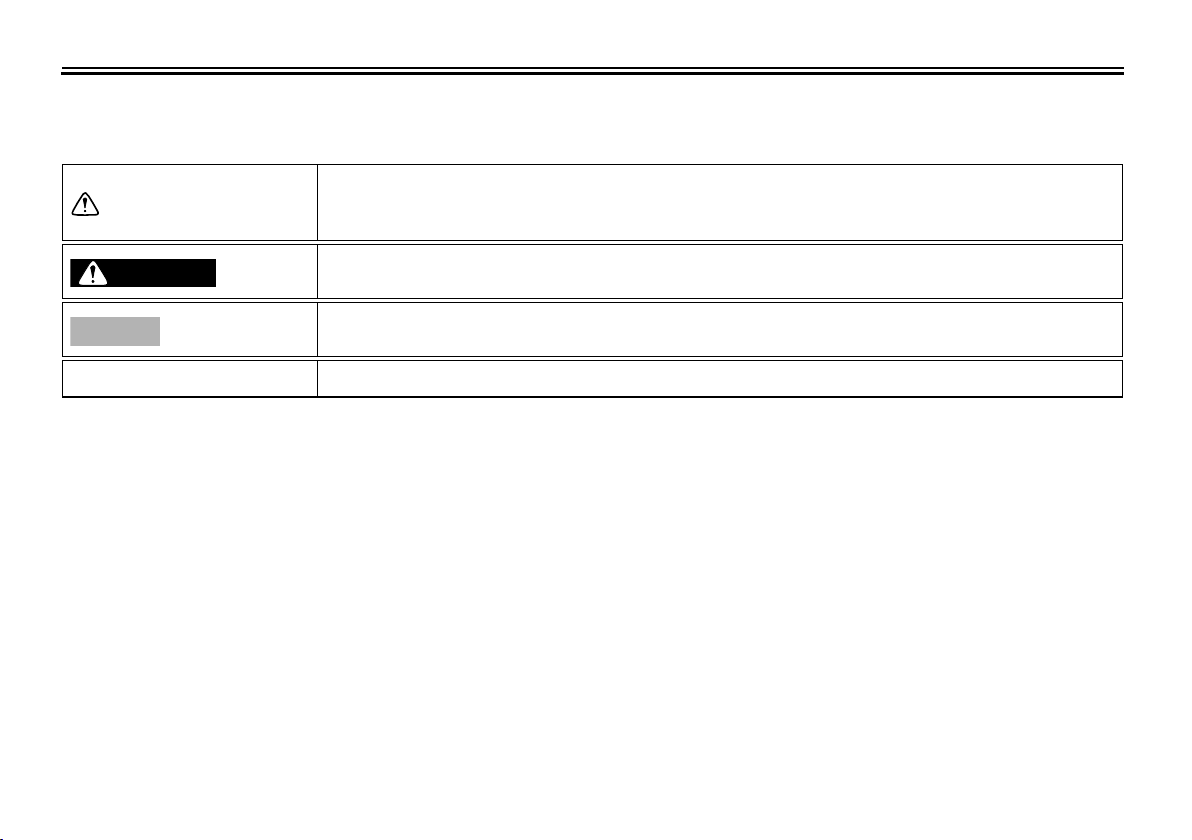
Particularly important information is distinguished in this manual by the following notations:
This is the safety alert symbol. It is used to alert you to potential personal injury
hazards. Obey all safety messages that follow this symbol to avoid possible injury
or death.
A WARNING indicates a hazardous situation which, if not avoided, could result in
death or serious injury.
A NOTICE indicates special precautions that must be taken to avoid damage to the
vehicle or other property.
A TIP provides key information to make procedures easier or clearer.
*Product and specifications are subject to change without notice.
EAU10134
Page 7
IMPORTANT MANUAL INFORMATION
EAU10201
YZF-R1/YZF-R1M
OWNER’S MANUAL
©2014 by Yamaha Motor Co., Ltd.
1st edition, December 2014
All rights reserved.
Any reprinting or unauthorized use
without the written permission of
Yamaha Motor Co., Ltd.
is expressly prohibited.
Printed in Japan.
Page 8

TABLE OF CONTENTS
SAFETY INFORMATION ................... 1-1
DESCRIPTION ................................... 2-1
Left view .......................................... 2-1
Right view........................................ 2-2
Controls and instruments................. 2-3
SPECIAL FEATURES ........................ 3-1
YRC (Yamaha Ride Control) ........... 3-1
Glossary .......................................... 3-3
YRC functions visual guide.............. 3-4
INSTRUMENT AND CONTROL
FUNCTIONS ....................................... 4-1
Immobilizer system.......................... 4-1
Main switch/steering lock................. 4-2
Handlebar switches ......................... 4-3
Indicator lights and warning lights ... 4-6
Display............................................. 4-8
MENU screen ................................ 4-14
Clutch lever.................................... 4-29
Shift pedal...................................... 4-30
Brake lever .................................... 4-30
Brake pedal ................................... 4-31
Brake system................................. 4-31
Fuel tank cap ................................. 4-33
Fuel................................................ 4-33
Fuel tank breather hose and
overflow hose ............................. 4-35
Catalytic converter......................... 4-35
Seats ............................................. 4-36
CCU (for equipped models) .......... 4-37
Document storage......................... 4-38
Rear view mirrors.......................... 4-39
Adjusting the front fork .................. 4-39
Adjusting the shock absorber
assembly.................................... 4-41
EXUP system................................ 4-45
Sidestand ...................................... 4-45
Ignition circuit cut-off system......... 4-46
Auxiliary DC connector.................. 4-48
FOR YOUR SAFETY –
PRE-OPERATION CHECKS ............. 5-1
OPERATION AND IMPORTANT
RIDING POINTS................................. 6-1
Starting the engine .......................... 6-1
Shifting ............................................ 6-2
Tips for reducing fuel
consumption ................................ 6-4
Engine break-in ............................... 6-4
Parking............................................ 6-5
PERIODIC MAINTENANCE AND
ADJUSTMENT ................................... 7-1
Owner’s tool kit................................ 7-2
Periodic maintenance chart for the
emission control system .............. 7-3
General maintenance and
lubrication chart ........................... 7-4
Removing and installing cowlings
and panels.................................... 7-8
Checking the spark plugs .............. 7-11
Engine oil and oil filter cartridge..... 7-12
Coolant .......................................... 7-14
Air filter element............................. 7-17
Checking the engine idling
speed.......................................... 7-17
Checking the throttle grip free
play............................................. 7-18
Valve clearance ............................. 7-18
Tires............................................... 7-18
Cast magnesium wheels................ 7-21
Adjusting the clutch lever free
play............................................. 7-22
Checking the brake lever free
play............................................. 7-22
Brake light switches....................... 7-23
Checking the front and rear brake
pads............................................ 7-23
Checking the brake fluid level........ 7-24
Changing the brake fluid................ 7-25
Drive chain slack............................ 7-25
Cleaning and lubricating the drive
chain........................................... 7-27
Checking and lubricating the
cables......................................... 7-27
Checking and lubricating the
throttle grip and cable................. 7-28
Checking and lubricating the
brake and shift pedals ................ 7-28
Page 9

Checking and lubricating the
brake and clutch levers .............. 7-29
Checking and lubricating the
sidestand.................................... 7-29
Lubricating the swingarm pivots .... 7-30
Checking the front fork .................. 7-30
Checking the steering.................... 7-31
Checking the wheel bearings ........ 7-31
Battery ........................................... 7-31
Replacing the fuses....................... 7-33
Vehicle lights ................................. 7-35
Supporting the motorcycle............. 7-36
Troubleshooting............................. 7-36
Troubleshooting charts.................. 7-37
MOTORCYCLE CARE AND
STORAGE .......................................... 8-1
Matte color caution .......................... 8-1
Care................................................. 8-1
Storage............................................ 8-4
SPECIFICATIONS.............................. 9-1
CONSUMER INFORMATION........... 10-1
Identification numbers ................... 10-1
TABLE OF CONTENTS
INDEX ............................................... 11-1
Page 10

SAFETY INFORMATION
1
Be a Responsible Owner
2
As the vehicle’s owner, you are responsible for the safe and proper operation
3
of your motorcycle.
Motorcycles are single-track vehicles.
4
Their safe use and operation are dependent upon the use of proper riding
techniques as well as the expertise of
5
the operator. Every operator should
know the following requirements before
6
riding this motorcycle.
He or she should:
7
Obtain thorough instructions from
a competent source on all aspects
8
of motorcycle operation.
Observe the warnings and mainte-
nance requirements in this Own-
9
10
11
er’s Manual.
Obtain qualified training in safe
and proper riding techniques.
Obtain professional technical ser-
vice as indicated in this Owner’s
Manual and/or when made neces-
sary by mechanical conditions.
12
Never operate a motorcycle with-
out proper training or instruction.
EAU1028B
Take a training course. Beginners
should receive training from a certified instructor. Contact an authorized motorcycle dealer to find out
about the training courses nearest
you.
Safe Riding
Perform the pre-operation checks each
time you use the vehicle to make sure it
is in safe operating condition. Failure to
inspect or maintain the vehicle properly
increases the possibility of an accident
or equipment damage. See page 5-1
for a list of pre-operation checks.
This motorcycle is designed to car-
ry the operator and a passenger.
The failure of motorists to detect
and recognize motorcycles in traffic is the predominating cause of
automobile/motorcycle accidents.
Many accidents have been caused
by an automobile driver who did
not see the motorcycle. Making
yourself conspicuous appears to
be very effective in reducing the
chance of this type of accident.
Therefore:
• Wear a brightly colored jacket.
1-1
• Use extra caution when you are
approaching and passing
through intersections, since intersections are the most likely
places for motorcycle accidents
to occur.
• Ride where other motorists can
see you. Avoid riding in another
motorist’s blind spot.
• Never maintain a motorcycle
without proper knowledge. Contact an authorized motorcycle
dealer to inform you on basic
motorcycle maintenance. Certain maintenance can only be
carried out by certified staff.
Many accidents involve inexperi-
enced operators. In fact, many operators who have been involved in
accidents do not even have a current motorcycle license.
• Make sure that you are qualified
and that you only lend your motorcycle to other qualified operators.
• Know your skills and limits.
Staying within your limits may
help you to avoid an accident.
• We recommend that you prac-
Page 11

SAFETY INFORMATION
tice riding your motorcycle
where there is no traffic until you
have become thoroughly familiar with the motorcycle and all of
its controls.
Many accidents have been caused
by error of the motorcycle operator. A typical error made by the operator is veering wide on a turn
due to excessive speed or undercornering (insufficient lean angle
for the speed).
• Always obey the speed limit and
never travel faster than warranted by road and traffic conditions.
• Always signal before turning or
changing lanes. Make sure that
other motorists can see you.
The posture of the operator and
passenger is important for proper
control.
• The operator should keep both
hands on the handlebar and
both feet on the operator footrests during operation to maintain control of the motorcycle.
• The passenger should always
hold onto the operator, the seat
strap or grab bar, if equipped,
with both hands and keep both
feet on the passenger footrests.
Never carry a passenger unless
he or she can firmly place both
feet on the passenger footrests.
Never ride under the influence of
alcohol or other drugs.
This motorcycle is designed for
on-road use only. It is not suitable
for off-road use.
Protective Apparel
The majority of fatalities from motorcycle accidents are the result of head injuries. The use of a safety helmet is the
single most critical factor in the prevention or reduction of head injuries.
Always wear an approved helmet.
Wear a face shield or goggles.
Wind in your unprotected eyes
could contribute to an impairment
of vision that could delay seeing a
hazard.
The use of a jacket, heavy boots,
trousers, gloves, etc., is effective in
preventing or reducing abrasions
or lacerations.
Never wear loose-fitting clothes,
otherwise they could catch on the
1-2
control levers, footrests, or wheels
and cause injury or an accident.
Always wear protective clothing
that covers your legs, ankles, and
feet. The engine or exhaust system become very hot during or after operation and can cause burns.
A passenger should also observe
the above precautions.
Avoid Carbon Monoxide Poisoning
All engine exhaust contains carbon
monoxide, a deadly gas. Breathing carbon monoxide can cause headaches,
dizziness, drowsiness, nausea, confusion, and eventually death.
Carbon Monoxide is a colorless, odorless, tasteless gas which may be present even if you do not see or smell any
engine exhaust. Deadly levels of carbon monoxide can collect rapidly and
you can quickly be overcome and unable to save yourself. Also, deadly levels of carbon monoxide can linger for
hours or days in enclosed or poorly
ventilated areas. If you experience any
symptoms of carbon monoxide poisoning, leave the area immediately, get
fresh air, and SEEK MEDICAL TREAT-
1
2
3
4
5
6
7
8
9
10
11
12
Page 12
SAFETY INFORMATION
MENT.
1
Do not run engine indoors. Even if
you try to ventilate engine exhaust
2
with fans or open windows and
doors, carbon monoxide can rap-
3
idly reach dangerous levels.
Do not run engine in poorly venti-
lated or partially enclosed areas
4
such as barns, garages, or carports.
Do not run engine outdoors where
5
engine exhaust can be drawn into
6
7
a building through openings such
as windows and doors.
Loading
Adding accessories or cargo to your
motorcycle can adversely affect stabili-
8
ty and handling if the weight distribution
of the motorcycle is changed. To avoid
9
the possibility of an accident, use extreme caution when adding cargo or
10
accessories to your motorcycle. Use
extra care when riding a motorcycle
that has added cargo or accessories.
11
Here, along with the information about
accessories below, are some general
12
guidelines to follow if loading cargo to
your motorcycle:
The total weight of the operator, passenger, accessories and cargo must
not exceed the maximum load limit.
Operation of an overloaded vehicle
could cause an accident.
Maximum load:
188 kg (414 lb)
When loading within this weight limit,
keep the following in mind:
Cargo and accessory weight
should be kept as low and close to
the motorcycle as possible. Securely pack your heaviest items as
close to the center of the vehicle as
possible and make sure to distribute the weight as evenly as possible on both sides of the motorcycle
to minimize imbalance or instability.
Shifting weights can create a sud-
den imbalance. Make sure that accessories and cargo are securely
attached to the motorcycle before
riding. Check accessory mounts
and cargo restraints frequently.
• Properly adjust the suspension
for your load (suspension-ad-
1-3
justable models only), and
check the condition and pressure of your tires.
• Never attach any large or heavy
items to the handlebar, front
fork, or front fender. These
items, including such cargo as
sleeping bags, duffel bags, or
tents, can create unstable handling or a slow steering response.
This vehicle is not designed to
pull a trailer or to be attached to
a sidecar.
Genuine Yamaha Accessories
Choosing accessories for your vehicle
is an important decision. Genuine
Yamaha accessories, which are available only from a Yamaha dealer, have
been designed, tested, and approved
by Yamaha for use on your vehicle.
Many companies with no connection to
Yamaha manufacture parts and accessories or offer other modifications for
Yamaha vehicles. Yamaha is not in a
position to test the products that these
aftermarket companies produce.
Therefore, Yamaha can neither en-
Page 13
SAFETY INFORMATION
dorse nor recommend the use of accessories not sold by Yamaha or
modifications not specifically recommended by Yamaha, even if sold and
installed by a Yamaha dealer.
Aftermarket Parts, Accessories,
and Modifications
While you may find aftermarket products similar in design and quality to
genuine Yamaha accessories, recognize that some aftermarket accessories
or modifications are not suitable because of potential safety hazards to you
or others. Installing aftermarket products or having other modifications performed to your vehicle that change any
of the vehicle’s design or operation
characteristics can put you and others
at greater risk of serious injury or death.
You are responsible for injuries related
to changes in the vehicle.
Keep the following guidelines in mind,
as well as those provided under “Loading” when mounting accessories.
Never install accessories or carry
cargo that would impair the performance of your motorcycle. Carefully inspect the accessory before
using it to make sure that it does
not in any way reduce ground
clearance or cornering clearance,
limit suspension travel, steering
travel or control operation, or obscure lights or reflectors.
• Accessories fitted to the handlebar or the front fork area can
create instability due to improper
weight distribution or aerodynamic changes. If accessories
are added to the handlebar or
front fork area, they must be as
lightweight as possible and
should be kept to a minimum.
• Bulky or large accessories may
seriously affect the stability of
the motorcycle due to aerodynamic effects. Wind may attempt to lift the motorcycle, or
the motorcycle may become unstable in cross winds. These accessories may also cause
instability when passing or being
passed by large vehicles.
• Certain accessories can displace the operator from his or
her normal riding position. This
improper position limits the free-
1-4
dom of movement of the operator and may limit control ability,
therefore, such accessories are
not recommended.
Use caution when adding electri-
cal accessories. If electrical accessories exceed the capacity of the
motorcycle’s electrical system, an
electric failure could result, which
could cause a dangerous loss of
lights or engine power.
Aftermarket Tires and Rims
The tires and rims that came with your
motorcycle were designed to match the
performance capabilities and to provide
the best combination of handling, braking, and comfort. Other tires, rims, sizes, and combinations may not be
appropriate. Refer to page 7-18 for tire
specifications and more information on
replacing your tires.
Transporting the Motorcycle
Be sure to observe following instructions before transporting the motorcycle in another vehicle.
Remove all loose items from the
motorcycle.
1
2
3
4
5
6
7
8
9
10
11
12
Page 14

1
2
3
4
5
6
7
8
9
10
11
SAFETY INFORMATION
Check that the fuel cock (if
equipped) is in the “OFF” position
and that there are no fuel leaks.
Point the front wheel straight
ahead on the trailer or in the truck
bed, and choke it in a rail to prevent movement.
Shift the transmission in gear (for
models with a manual transmission).
Secure the motorcycle with
tie-downs or suitable straps that
are attached to solid parts of the
motorcycle, such as the frame or
upper front fork triple clamp (and
not, for example, to rubber-mounted handlebars or turn signals, or
parts that could break). Choose
the location for the straps carefully
so the straps will not rub against
painted surfaces during transport.
The suspension should be com-
pressed somewhat by the
tie-downs, if possible, so that the
motorcycle will not bounce excessively during transport.
12
1-5
Page 15
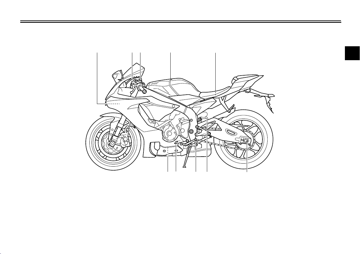
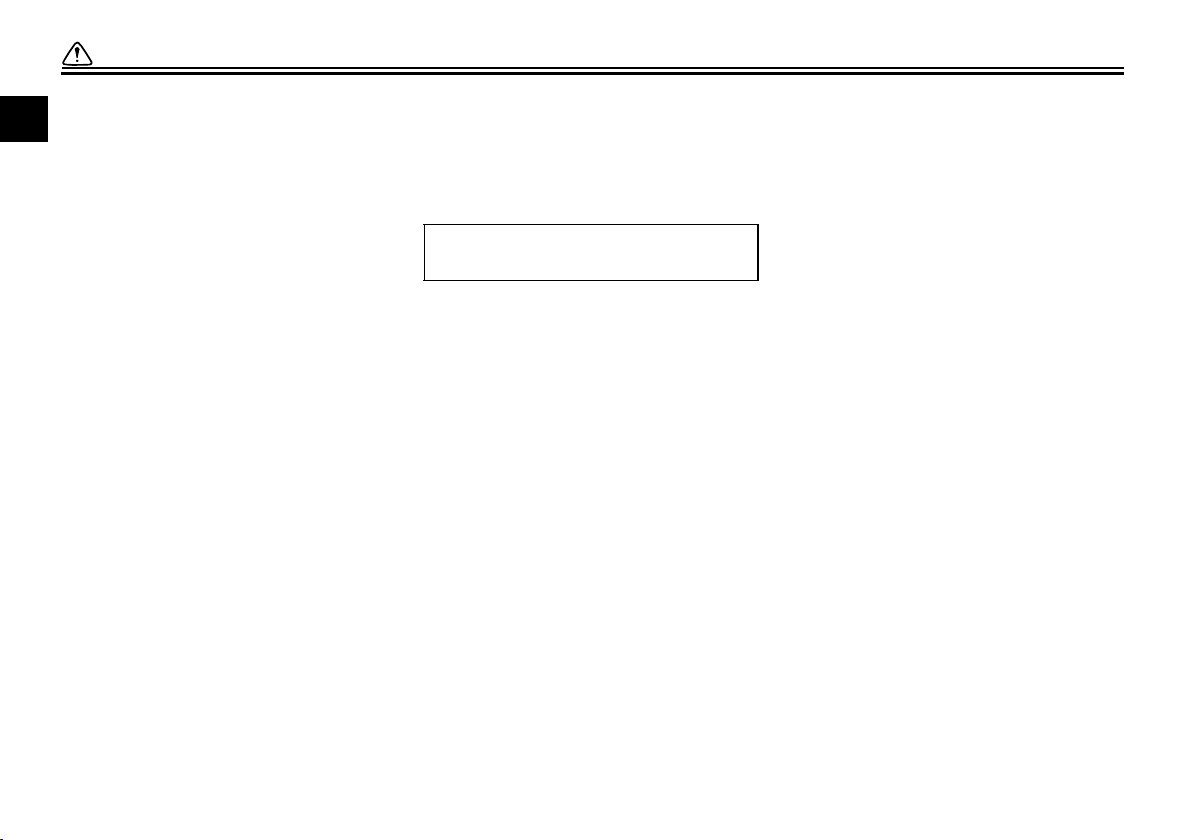
Left view
1
3
4 5,6
10 89
2
11 7
DESCRIPTION
EAU10411
1
2
3
4
5
1. Fuse box (page 7-33)
2. ERS coupler (YZF-R1M) (page 4-39)
3. Spring preload adjusting bolt (YZF-R1M) (page 4-39)
4. Fuel tank cap (page 4-33)
5. Battery (page 7-31)
6. Main fuse (page 7-33)
7. Drive chain puller (page 7-25)
8. Spring preload adjusting ring (page 4-41)
9. Shift pedal (page 4-30)
10.Engine oil level check window (page 7-12)
11.Engine oil filter cartridge (page 7-12)
2-1
6
7
8
9
10
11
12
Page 16
DESCRIPTION
32
4
6
7
5
1
8,9,10
1
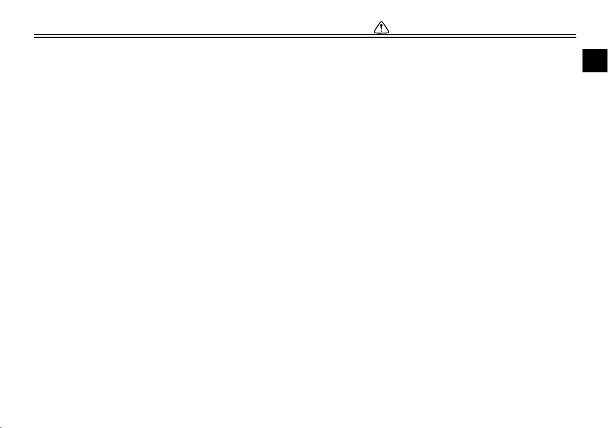
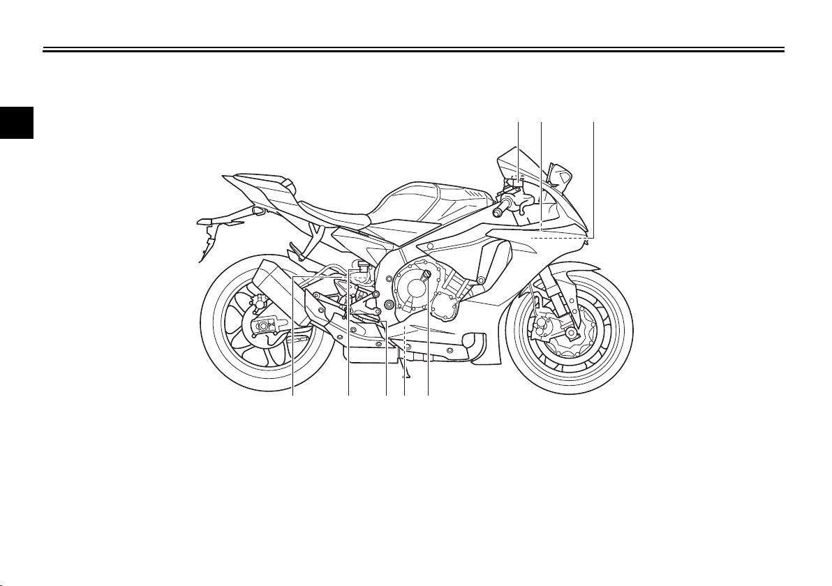
Right view
2
3
4
5
EAU10421
6
7
8
9
1. Front brake fluid reservoir (page 7-24)
10
2. Document storage space (page 4-38)
3. Radiator cap (page 7-14)
4. Engine oil filler cap (page 7-12)
11
5. Coolant drain bolt (page 7-15)
6. Brake pedal (page 4-31)
12
7. Rear brake fluid reservoir (page 7-24)
8. Fast compression damping force adjusting bolt (page 4-41)
9. Slow compression damping force adjusting screw (page 4-41)
10.Rebound damping force adjusting screw (page 4-41)
2-2
Page 17
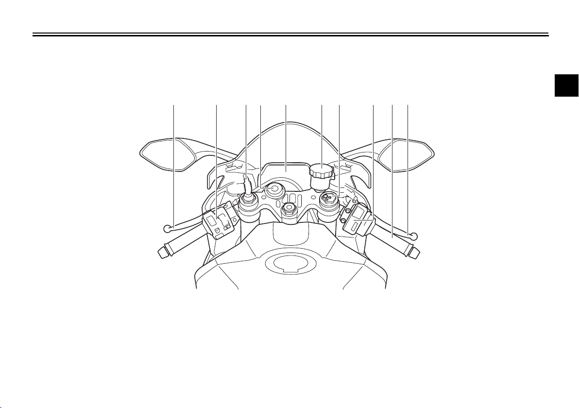
Controls and instruments
12456 1011123 7,8,9
DESCRIPTION
EAU10431
1
2
3
4
5
6
1. Clutch lever (page 4-29)
2. Left handlebar switches (page 4-3)
3. ERS coupler (YZF-R1M) (page 4-39)
4. Main switch/steering lock (page 4-2)
5. Instrument panel (page 4-6, 4-8)
6. Front brake fluid reservoir (page 7-24)
7. Spring preload adjusting nut (YZF-R1) (page 4-39)
8. Rebound damping force adjusting bolt (YZF-R1) (page 4-39)
9. Compression damping force adjusting bolt (YZF-R1) (page 4-39)
10.Right handlebar switches (page 4-3)
11.Throttle grip (page 7-18)
12.Brake lever (page 4-30)
2-3
7
8
9
10
11
12
Page 18
SPECIAL FEATURES
WARNING
5
6
4
3
2
1
1
YRC (Yamaha Ride Control)
Yamaha Ride Control is a system that
incorporates numerous sensors and
2
controls to support an improved riding
experience. The vehicle senses and
3
can react to forces along the longitudal
(front-to-back), lateral (left-to-right),
4
and vertical (up-and-down) axes. Lean
angle and G-force accelerations are
also detected. This information is pro-
5
cessed multiple times a second and the
related physical systems are automati-
6
cally adjusted as necessary. The functions listed below represent individual
7
YRC items which can be turned on/off
or adjusted to suit various riders and
riding conditions. For setting details see
8
“MENU” on page 4-14.
9
The Yamaha Ride Control (YRC) sys-
10
tem is not a substitute for the use of
proper riding techniques or the expertise of the operator. This system
11
cannot prevent loss of control
caused by rider errors such as trav-
12
eling faster than warranted by road
and traffic conditions, including loss
EAU66291
EWA18220
of traction due to excessive speed
when entering turns, when accelerating hard at a sharp lean angle, or
while braking, and it cannot prevent
front wheel slipping or lift (“wheelies”). As with any motorcycle, always ride within in your limits, be
aware of surrounding conditions,
and ride appropriately for those conditions. Become thoroughly familiar
with the way the motorcycle handles
with various YRC settings before attempting more advanced maneuvers.
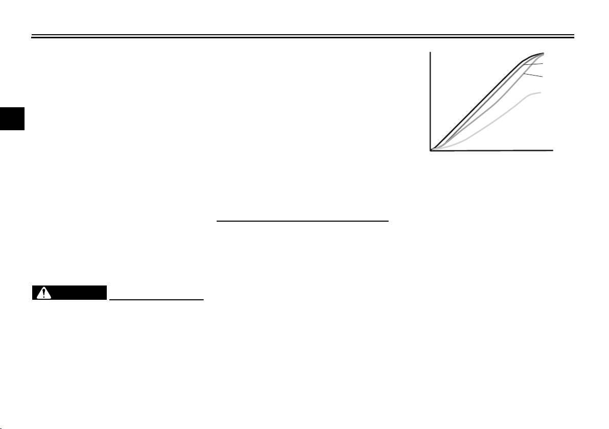
PWR
The power delivery mode system consists of four different control maps
which regulate throttle valve opening in
relation to the degree of throttle grip operation, thus providing you with a selection of modes to fit your preferences
and the riding environment.
3-1
1. PWR 1
2. PWR 2
3. PWR 3
4. PWR 4
5. Throttle valve opening
6. Throttle grip operation
TCS
The traction control system helps maintain traction when accelerating. If sensors detect that the rear wheel is
starting to slip (uncontrolled spinning),
the traction control system assists by
regulating engine power as needed until traction is restored. The traction control system indicator/warning light
flashes to let the rider know that traction
control has engaged.
This traction control system automati-
Page 19
SPECIAL FEATURES
TIP
WARNING
TIP
NOTICE
cally adjusts according to the vehicle’s
lean angle. To maximize acceleration,
when the vehicle is upright a less
amount of traction control is applied.
When cornering, a greater amount of
traction control is applied.
TCS
The traction control system may
engage when the vehicle travels
over a bump.
You may notice slight changes in
engine and exhaust sounds when
the traction control or other YRC
systems engage.
When TCS is turned off, SCS,
LCS, and LIF are also turned off
automatically.
EWA15432
The traction control system is not a
substitute for riding appropriately
for the conditions. Traction control
cannot prevent loss of traction due
to excessive speed when entering
turns, when accelerating hard at a
sharp lean angle, or while braking,
and cannot prevent front wheel slipping. As with any motorcycle, approach surfaces that may be
slippery with caution and avoid especially slippery surfaces.
When the key is turned to “ON”, the
traction control system automatically
turns on. The traction control system
can be turned on or off manually only
when the key is in the “ON” position and
the motorcycle is stopped.
Turn the traction control system off to
help free the rear wheel if the motorcycle gets stuck in mud, sand, or other
soft surfaces.
ECA16801
Use only the specified tires. (See
page 7-18.) Using different sized
tires will prevent the traction control
system from controlling tire rotation
accurately.
SCS
The slide control system regulates engine power output when a sideward
slide is detected in the rear wheel. It adjusts power output based on data from
the IMU. This system supports the TCS
to contribute to a smoother ride.
LCS
The launch control system helps the
rider achieve smooth and swift
launches from the starting grid. It
keeps engine speed from rising above
10,000 r/min even when the throttle
grip is fully turned. The LCS regulates
engine power output in conjunction
with the TCS and LIF systems for optimal traction and reduced wheel lift.
1
2
3
4
5
6
7
8
9
10
11
12
3-2
Page 20
SPECIAL FEATURES
NOTICE
TIP
TIP
1
Even when using LCS, the clutch le-
2
ver must be released gradually to
avoid clutch damage.
3
LCS is intended for track use only.
4
QSS
5
The quick shift system allows for
full-throttle, clutch lever-less, electroni-
6
cally-assisted upshifts. When the
switch positioned on the shift lever rod
detects motion in the shift lever, engine
7
power output is adjusted and drive
torque is momentarily cancelled out to
8
allow for the gear change to occur.
9
QSS operates when traveling at
least 20 km/h with an engine
10
speed of 2000 r/min or higher and
only when accelerating.
11
QSS does not operate when the
clutch lever is pulled.
ECA22950
LIF
The lift control system reduces the rate
at which the front wheel will continue to
rise during extreme acceleration, such
as during starts or out-of-corner exits.
When front-wheel lift is detected, engine power is regulated to slow
front-wheel lift while still providing good
acceleration.
ERS (YZF-R1M)
The Electronic Racing Suspension by
Öhlins features electrically-controlled
suspension damping. The system is
controlled by the SCU which makes independent adjustments of both the
front and rear suspension’s compression stroke and rebound stroke damping forces. There are two modes,
automatic and manual. Automatic
mode is an active suspension control
system which actively adjusts suspension damping forces based on running
conditions. Manual mode is a finely-tuneable traditional suspension set-up.
EAU66311
Glossary
ABS - Anti-lock Brake System
ABS ECU - Anti-lock Brake System
Electronic Control Unit
CCU - Communication Control Unit
ECU - Engine Control Unit
ERS - Electronic Racing Suspension
GPS - Global Positioning System
IMU - Inertial Measurement Unit
LCS - Launch Control System
LIF - Lift Control System
PWR - Power delivery mode
QSS - Quick Shift System
SC - Stability Control
SCS - Slide Control System
SCU - Suspension Control Unit
TCS - Traction Control System
UBS - Unified Brake System
YRC - Yamaha Ride Control
12
3-3
Page 21
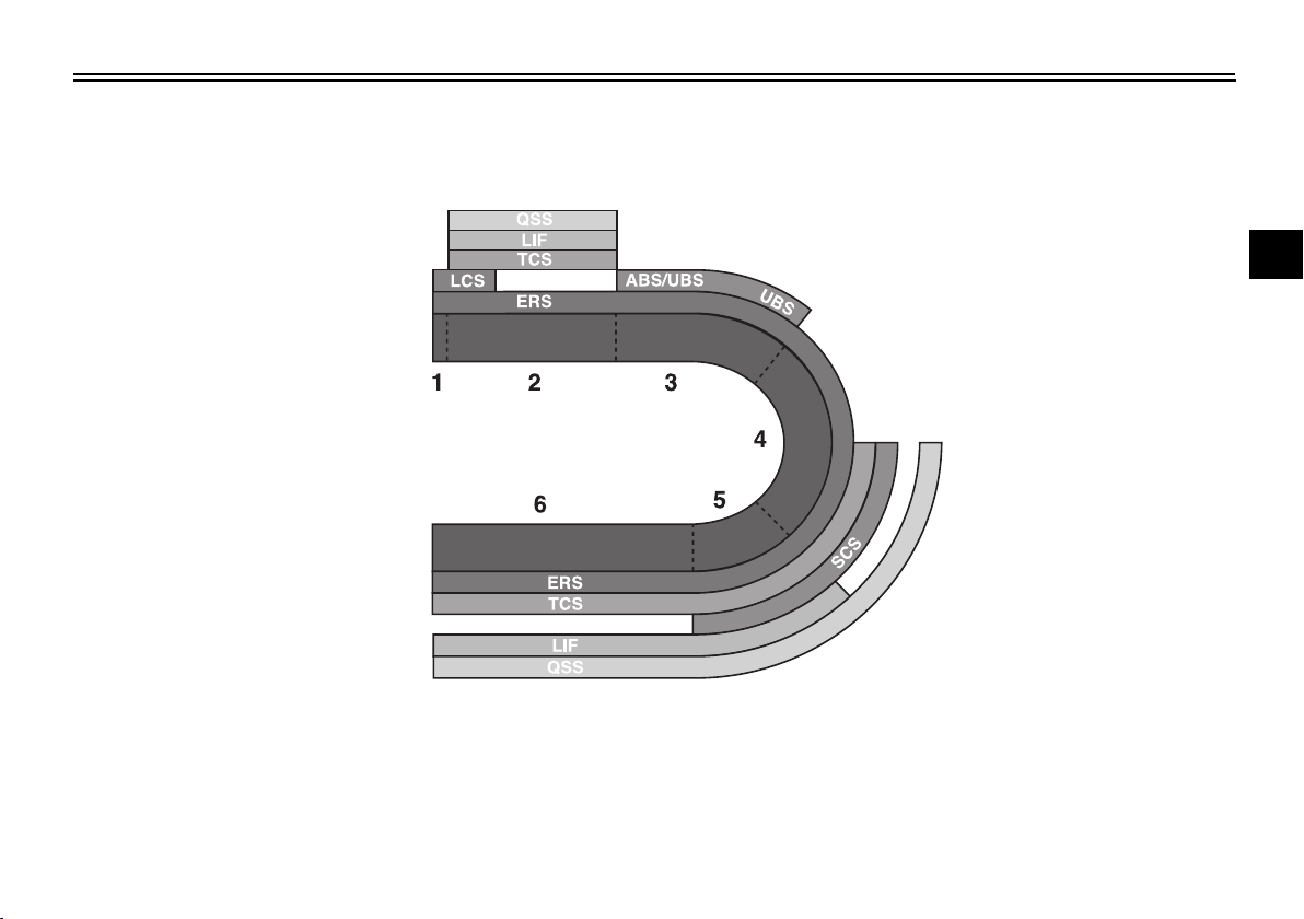
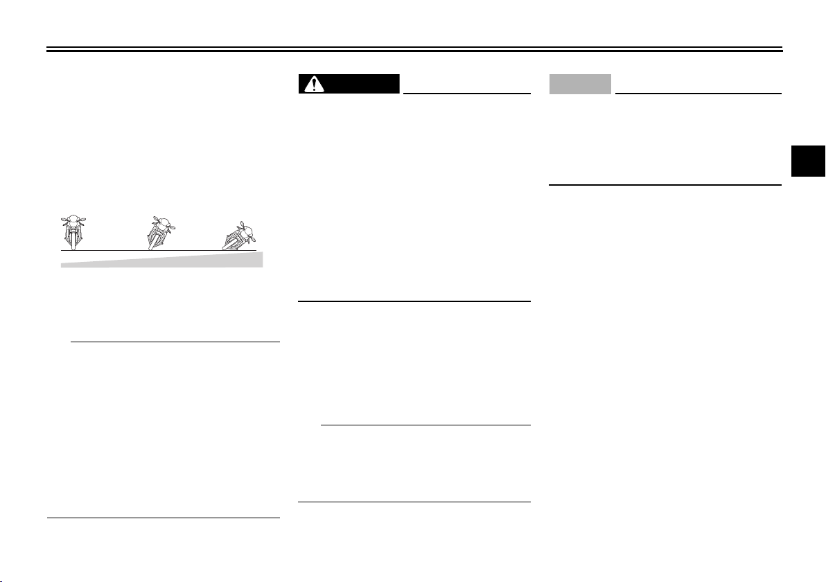
YRC functions visual guide
SPECIAL FEATURES
EAU66910
1
2
3
4
5
6
7
8
9
10
1. Start
2. Acceleration
3. Braking
4. Apex
5. Exit
6. Straightaway
3-4
11
12
Page 22
INSTRUMENT AND CONTROL FUNCTIONS
NOTICE
1
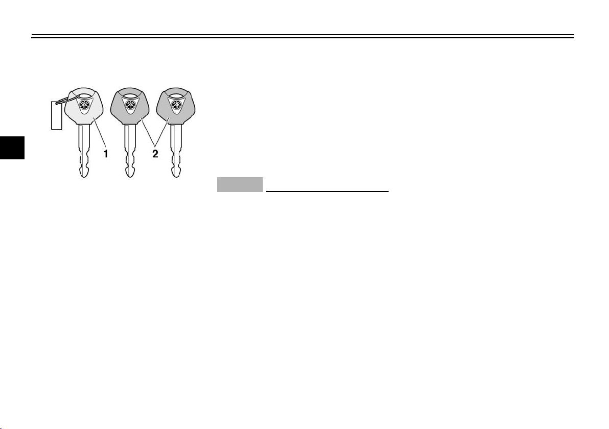
Immobilizer system
2
3
4
5
1. Code re-registering key (red bow)
6
2. Standard keys (black bow)
This vehicle is equipped with an immo-
7
bilizer system to help prevent theft by
re-registering codes in the standard
keys. This system consists of the fol-
8
lowing:
a code re-registering key (with a
9
10
red bow)
two standard keys (with a black
bow) that can be re-registered with
new codes
11
a transponder (which is installed in
the code re-registering key)
12
an immobilizer unit
an ECU
an immobilizer system indicator
EAU10978
light (See page 4-7.)
The key with the red bow is used to register codes in each standard key. Since
re-registering is a difficult process, take
the vehicle along with all three keys to
a Yamaha dealer to have them re-registered. Do not use the key with the red
bow for driving. It should only be used
for re-registering the standard keys. Always use a standard key for driving.
ECA11822
DO NOT LOSE THE CODE
RE-REGISTERING KEY! CON-
TACT YOUR DEALER IMMEDI-
ATELY IF IT IS LOST! If the code
re-registering key is lost, regis-
tering new codes in the stan-
dard keys is impossible. The
standard keys can still be used
to start the vehicle, however if
code re-registering is required
(i.e., if a new standard key is
made or all keys are lost) the en-
tire immobilizer system must be
replaced. Therefore, it is highly
recommended to use either
standard key and keep the code
re-registering key in a safe
4-1
place.
Do not submerse any key in wa-
ter.
Do not expose any key to exces-
sively high temperatures.
Do not place any key close to
magnets (this includes, but not
limited to, products such as
speakers, etc.).
Do not place items that transmit
electrical signals close to any
key.
Do not place heavy items on any
key.
Do not grind any key or alter its
shape.
Do not disassemble the plastic
part of any key.
Do not put two keys of any im-
mobilizer system on the same
key ring.
Keep the standard keys as well
as keys of other immobilizer
systems away from this vehicle’s code re-registering key.
Keep other immobilizer system
keys away from the main switch
as they may cause signal inter-
Page 23
INSTRUMENT AND CONTROL FUNCTIONS
TIP
TIP
WARNING
P
ON
OFF
LOCK
ference.
EAU10474
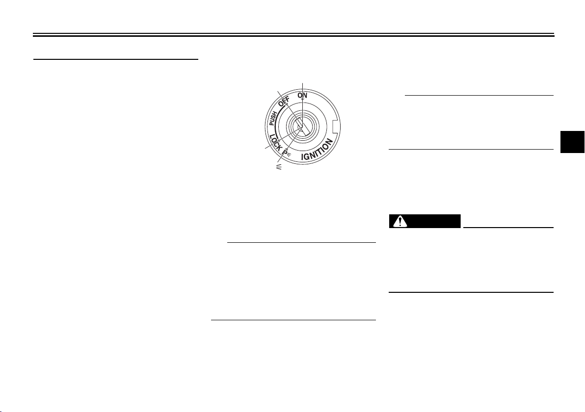
Main switch/steering lock
The main switch/steering lock controls
the ignition and lighting systems, and is
used to lock the steering. The various
positions are described below.
Be sure to use the standard key (black
bow) for regular use of the vehicle. To
minimize the risk of losing the code
re-registering key (red bow), keep it in a
safe place and only use it for code
re-registering.
EAU10551
ON
All electrical circuits are supplied with
power, the meter lighting, taillight, li-
4-2
cense plate light and auxiliary lights
come on, and the engine can be started. The key cannot be removed.
The headlights come on automatically
when the engine is started and stay on
until the key is turned to “OFF”, even if
the engine stalls.
EAU10662
OFF
All electrical systems are off. The key
can be removed.
EWA10062
Never turn the key to “OFF” or
“LOCK” while the vehicle is moving.
Otherwise the electrical systems will
be switched off, which may result in
loss of control or an accident.
EAU10685
LOCK
The steering is locked, and all electrical
systems are off. The key can be removed.
1
2
3
4
5
6
7
8
9
10
11
12
Page 24
INSTRUMENT AND CONTROL FUNCTIONS
NOTICE
12
12
12
543
To lock the steering
1
2
3
4
5
1. Push.
2. Turn.
6
1. Turn the handlebars all the way to
7
the left.
2. Push the key in from the “OFF” position, and then turn it to “LOCK”
8
while still pushing it.
3. Remove the key.
9
10
To unlock the steering
1. Push.
2. Turn.
Push the key in, and then turn it to
“OFF” while still pushing it.
EAU65680
(Parking)
The hazard lights can be turned on, but
all other electrical systems are off. The
key can be removed.
The steering must be locked before the
key can be turned to “ ”.
ECA22330
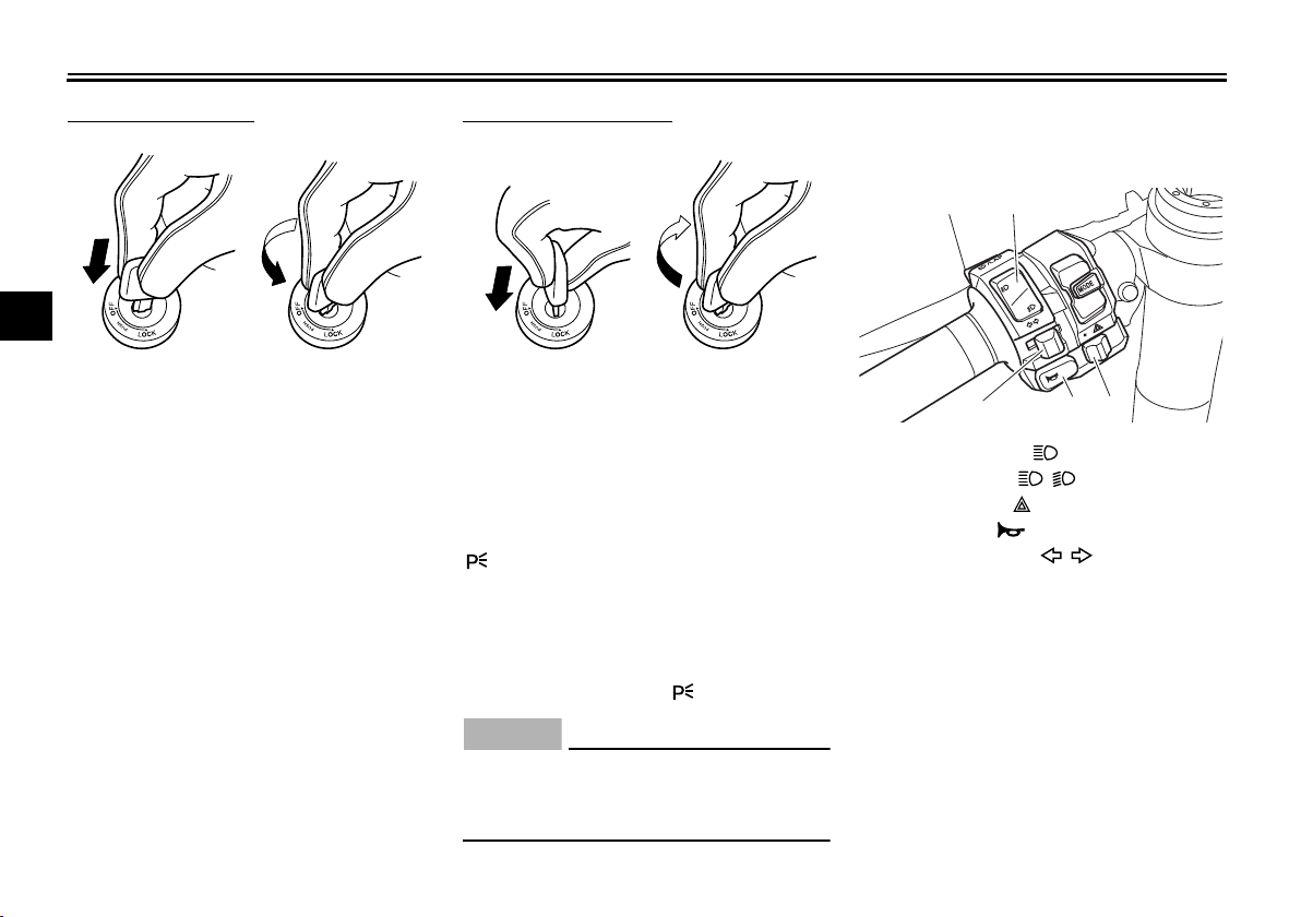
EAU66050
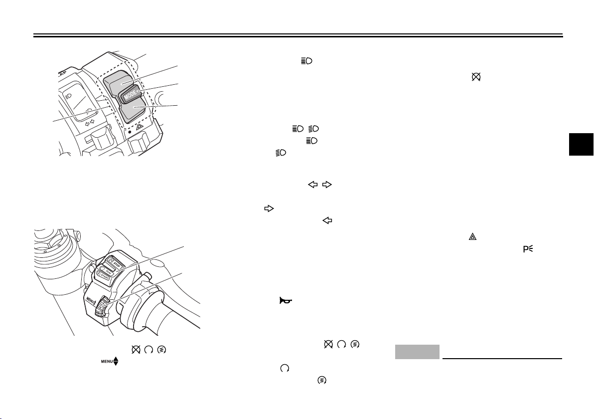
Handlebar switches
Left
1. Pass/LAP switch “ /LAP”
2. Dimmer switch “ / ”
3. Hazard switch “ ”
4. Horn switch “ ”
5. Turn signal switch “ / ”
11
12
Using the hazard lights for an extended length of time may cause the
battery to discharge.
4-3
Page 25
INSTRUMENT AND CONTROL FUNCTIONS
NOTICE
1
2
1
1. Mode switch “MODE”
2. Up button
3. Center button
4. Down button
Right
1. Stop/Run/Start switch “ / / ”
2. Wheel switch “ ”
EAU66091
2
3
Pass/LAP switch “ /LAP”
Press this switch to flash the headlights
and to mark the start of each lap when
using the lap timer.
4
EAU66020
Dimmer switch “ / ”
Set this switch to “ ” for the high
beam and to “ ” for the low beam.
EAU66040
Turn signal switch “ / ”
To signal a right-hand turn, push this
switch to “ ”. To signal a left-hand
turn, push this switch to “ ”. When released, the switch returns to the center
position. To cancel the turn signal
lights, push the switch in after it has returned to the center position.
EAU66030
Horn switch “ ”
Press this switch to sound the horn.
EAU66060
Stop/Run/Start switch “ / / ”
6-1 for starting instructions prior to
starting the engine.
Set this switch to “ ” to stop the engine
in case of an emergency, such as when
the vehicle overturns or when the throttle cable is stuck.
EAU67360
The engine trouble and system warning
light and ABS warning light may come
on when the key is turned to “ON” and
the start switch is pushed, but this does
not indicate a malfunction.
EAU66010
Hazard switch “ ”
With the key in the “ON” or “ ” position, use this switch to turn on the hazard lights (simultaneous flashing of all
turn signal lights).
The hazard lights are used in case of
an emergency or to warn other drivers
when your vehicle is stopped where it
might be a traffic hazard.
ECA10062
1
2
3
4
5
6
7
8
9
10
11
To crank the engine with the starter, set
this switch to “ ”, and then push the
switch down towards “ ”. See page
Do not use the hazard lights for an
extended length of time with the en-
12
4-4
Page 26
INSTRUMENT AND CONTROL FUNCTIONS
TIP
TIP
10
11
12
gine not running, otherwise the bat-
1
tery may discharge.
2
Mode switch “MODE”
Use the mode switch to change YRC
3
modes or edit the PWR, TCS, and SCS
settings from the main screen. This
4
switch has three buttons.
Up button - push this button to change
5
the selected YRC setting upward.
Center button - push this button to
scroll left to right among the MODE,
6
PWR, TCS, and SCS items.
Down button - push this button to
7
change the selected YRC setting
downward.
8
The center button is also used to
9
activate the launch control system.
When the LCS icon is grey, push
and hold the center button. The
LCS icon will flash and turn white
when the system has been activated.
The traction control system can
only be turned off from the main
screen. Select TCS with the center
EAU66111
button, then push and hold the up
button until TCS OFF is displayed.
To turn the traction control system
back on, use the down button.
When TCS has been turned off,
the SCS, LCS, and LIF systems
are also turned off for all YRC
modes.
See “YRC Setting” on page 4-15
for more information on how to
customize YRC modes and adjust
YRC item setting levels.
EAU66100
Wheel switch “ ”
When the main screen is set to
STREET MODE, use the wheel switch
to scroll and reset the information display items.
When the main screen is set to TRACK
MODE, use the wheel switch to scroll
and reset the information display items
and to activate the lap timer.
When the display has been changed to
the MENU screen, use the wheel
switch to navigate the setting modules
and make setting changes.
Operate the wheel switch as follows.
Rotate up - rotate the wheel upward to
4-5
scroll up/left or increase a setting value.
Rotate down - rotate the wheel downward to scroll down/right or decrease a
setting value.
Short push - briefly press the switch inward to make and confirm selections.
Long push - press the switch inward
for one second to reset an information
display item or to access and exit the
MENU screen.
See page 4-8 for more information
on the main screen and its functions.
See page 4-14 for more informa-
tion on the MENU screen and how
to make setting changes.
Page 27
INSTRUMENT AND CONTROL FUNCTIONS
TIP
WARNING
ABS
ABS
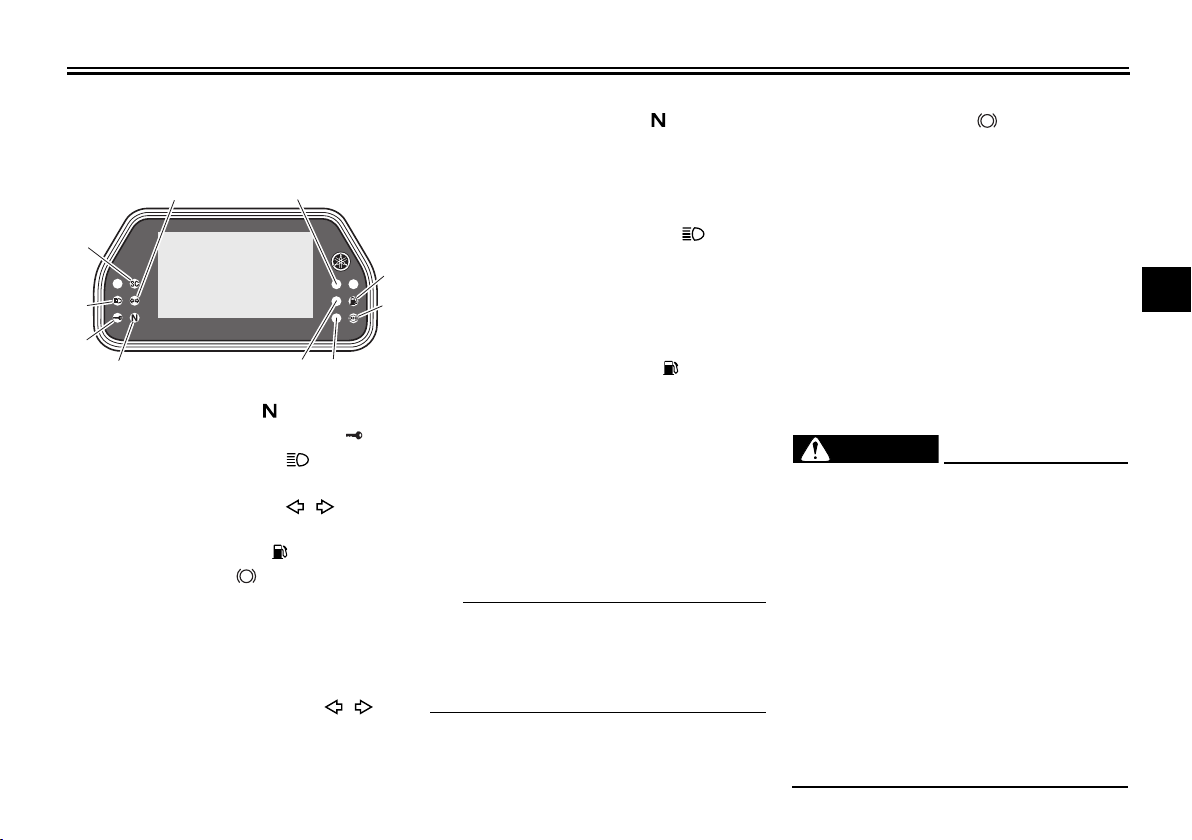
EAU49398
Indicator lights and warning lights
56
4
7
3
2
1109
1. Neutral indicator light “ ”
2. Immobilizer system indicator light “ ”
3. High beam indicator light “ ”
4. Stability control indicator light “SC”
5. Turn signal indicator light “ ”
6. Shift timing indicator light
7. Fuel level warning light “ ”
8. ABS warning light “ ”
9. Engine trouble and system warning light
10.Oil pressure and coolant temperature
warning light
Turn signal indicator light “ ”
This indicator light flashes when a turn
signal light is flashing.
8
EAU11022
EAU11061
Neutral indicator light “ ”
This indicator light comes on when the
transmission is in the neutral position.
EAU11081
High beam indicator light “ ”
This indicator light comes on when the
high beam of the headlight is switched
on.
EAU66890
Fuel level warning light “ ”
This warning light comes on when the
fuel level drops below approximately
3.0 L (0.79 US gal, 0.66 Imp.gal). When
this occurs, refuel as soon as possible.
The electrical circuit of the warning light
can be checked by turning the key to
“ON”. The warning light should come
on for a few seconds and then go off.
If the warning light does not come on at
all, remains on after refueling, or if the
warning light flashes repeatedly, have
a Yamaha dealer check the vehicle.
EAU66501
ABS warning light “ ”
In normal operation, the ABS warning
light comes on when the key is turned
to “ON”, and goes off after traveling at a
speed of 10 km/h (6 mi/h) or higher.
If the warning light does not work as described above, or if the warning light
comes on while riding, the ABS and
UBS may not work correctly. Have a
Yamaha dealer check the vehicle as
soon as possible. (See “Brake system”
on page 4-31 for an explanation of ABS
and UBS.)
EWA16041
If the ABS warning light does not go
off after traveling at a speed of 10
km/h (6 mi/h) or higher, or if the
warning light comes on or flashes
while riding, the brake system reverts to conventional braking. If either of the above occurs, or if the
warning light does not come on at
all, use extra caution to avoid possible wheel lock during emergency
braking. Have a Yamaha dealer
check the brake system and electrical circuits as soon as possible.
1
2
3
4
5
6
7
8
9
10
11
12
4-6
Page 28

INSTRUMENT AND CONTROL FUNCTIONS
NOTICE
1
Shift timing indicator light
This indicator light can be set to come
on and go off at the desired engine
2
speeds and is used to inform the rider
when it is time to shift to the next higher
3
gear.
The electrical circuit of the indicator
light can be checked by turning the key
4
to ON. The indicator light should come
on for a few seconds, and then go off.
5
If the indicator light does not come on
initially when the key is turned to ON, or
6
if the indicator light remains on, have a
Yamaha dealer check the electrical circuit. (See page 4-23 for a detailed ex-
7
planation of the function of this indicator
light and on how to set it.)
8
Immobilizer system indicator light
9
“”
When the key is turned to “OFF” and 30
10
seconds have passed, the indicator
light will start flashing indicating the im-
11
mobilizer system is enabled. After 24
hours have passed, the indicator light
will stop flashing, however the immobi-
12
lizer system is still enabled.
EAU67430
EAU66901
The electrical circuit of the indicator
light can be checked by turning the key
to ON. The indicator light should come
on for a few seconds, and then go off. If
the indicator light does not operate as
described above, have a Yamaha dealer check the vehicle.
If a problem is detected in the immobilizer system, the immobilizer system indicator light will flash and the display
will indicate an error code. (See “Error
mode” on page 4-13.)
EAU65980
Stability control indicator light “SC”
This indicator light comes on when the
TCS, SCS, or LIF systems have engaged. It will also come on if the TCS is
set to “OFF” or if the TCS system becomes disabled while riding.
The electrical circuit of the light can be
checked by turning the key to “ON”.
The light should come on for a few seconds and then go off. If the light does
not come on initially when the key is
turned to “ON”, or if the light remains
on, have a Yamaha dealer check the
vehicle.
EAU65991
Oil pressure and coolant temperature warning light
This warning light comes on if the engine oil pressure is low or if the coolant
temperature is high. If this occurs, stop
the engine immediately.
The electrical circuit of the warning light
can be checked by turning the key to
“ON”. The warning light should come
on again after going off briefly, and then
remain on until the engine is started. If
the warning light does not come on initially when the key is turned to “ON”,
have a Yamaha dealer check the electrical circuit.
ECA22441
If the oil pressure and coolant warning light does not go off after starting the engine or if it comes on while
the engine is running, stop the vehicle and engine immediately.
If the engine is overheating, the
coolant temperature warning
icon will come on. Let the engine cool. Check the coolant
level (see page 7-38).
If the engine oil pressure is low,
4-7
Page 29

INSTRUMENT AND CONTROL FUNCTIONS
TIP
the oil pressure warning icon
will come on. Check the oil level
(see page 7-12).
If the warning light remains on
after letting the engine cool and
confirming the proper oil level,
have a Yamaha dealer check the
vehicle. Do not continue to operate the vehicle!
EAU66002
Engine trouble and system warning
light
If a problem is detected in any of the circuits monitoring the engine or YRC systems, this warning light will come on
and the display will switch to error
mode. (See page 4-13.)
The electrical circuit of the warning light
can be checked by turning the key to
ON. The light should come on briefly
and then go off. If the indicator does not
come on or remains on, have a
Yamaha dealer check the vehicle.
EAU66323
Display
The display has two different main
screen display modes, STREET
MODE and TRACK MODE. Most of the
functions are viewable in either mode,
but the layout differs slightly. The following items can be found on the display.
Speedometer
Tachometer
Information display
Transmission gear display
Front brake pressure indicator
Acceleration indicator
YRC setting display MODE/PWR/
TCS/SCS
YRC setting display LCS/QS/LIF
ERS indicator (ERS-equipped
models)
GPS indicator (CCU-equipped
models)
Clock
Revolution peak hold indicator
Lap timer
Oil pressure warning icon
Coolant temperature warning icon
Error mode “Err”
This model uses a thin-film-transistor
liquid-crystal display (TFT LCD) for
good contrast and readability in various
lighting conditions. However, due to the
nature of this technology, it is normal
for a small number of pixels to be inactive.
1
2
3
4
5
6
7
8
9
10
11
12
4-8
Page 30
INSTRUMENT AND CONTROL FUNCTIONS
TIP
NOTICE
ODO
12345
km
TRIP-2
1234.5
km
1
N
2
km/h
×
1000 r/min
MODE
-
A
PWR 1TCS 1SCS
1
A-1
LCS
QS LIF
GPS
12:00
7
11 10
8
9
41 2 365
13
12
MODE
-
A
PWR 1TCS 1SCS
1
km/h
123
ODO
km
7890
GEAR
N
LAP
09
LATEST
12
12 34
×
1000 r/min
A-1
LCLCS
QS
LIF
12:00
11
10
9
8
541 2 36
7
1
2
3
4
5
6
7
8
9
10
11
12
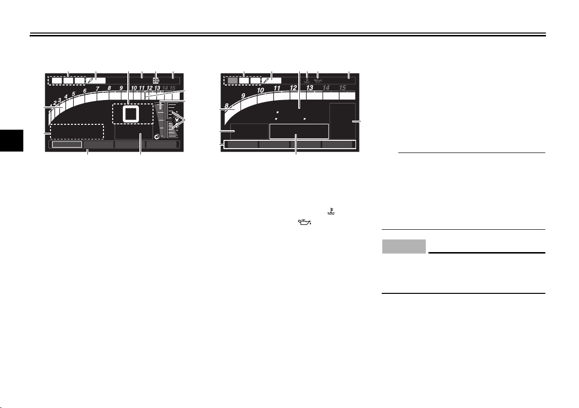
STREET MODE TRACK MODE
1. YRC items LCS/QS/LIF
2. ERS indicator (YZF-R1M)
3. Speedometer
4. GPS indicator (CCU-equipped models)
5. Logging indicator (CCU-equipped models)
6. Clock
7. Revolution peak hold indicator
8. Front brake pressure indicator
9. Acceleration indicator
10.Transmission gear display
11.YRC items MODE/PWR/TCS/SCS
12.Information display
13.Tachometer
1. YRC items LCS/QS/LIF
2. ERS indicator (YZF-R1M)
3. Lap timer
4. Coolant temperature warning “ ”
5. Oil pressure warning “ ”
6. Clock
7. Transmission gear display
8. Information display
9. YRC items MODE/PWR/TCS/SCS
10.Speedometer
11.Tachometer
Speedometer
The speedometer shows the vehicle’s
traveling speed. For certain markets,
the display can be switched between kilometers and miles. (See “Unit” on
page 4-22.)
Tachometer
The tachometer shows the engine
speed, as measured by the rotational
velocity of the crankshaft, in revolutions
per minute (r/min). When the vehicle is
first powered on, the tachometer will
sweep across the r/min range and then
return to zero.
In TRACK MODE, the tachometer
starts at 8000 r/min.
In STREET MODE, the tachome-
ter can be color-adjusted and has
a revolution peak hold indicator
which can be turned on or off.
ECA10032
Do not operate the engine in the tachometer red zone.
Red zone: 14000 r/min and above
Information display
This section of the main screen is used
to show additional riding related information such as air and coolant temperature readings, tripmeters, and fuel
consumption statistics. The information
4-9
Page 31

INSTRUMENT AND CONTROL FUNCTIONS
TIP
TIP
display items can be set into four
groups via the MENU screen.
The information display items are:
A.TEMP: air temperature
C.TEMP: coolant temperature
TRIP-1: tripmeter 1
TRIP-2: tripmeter 2
F-TRIP: fuel tripmeter
ODO: odometer
FUEL CON: the amount of fuel consumed
FUEL AVG: average fuel consumption
CRNT FUEL: current fuel consumption
F-TRIP appears automatically
when the fuel tank reserve level
has been reached and begins recording distance travelled from
that point.
After refueling and travelling some
distance, F-TRIP will automatically
disappear.
In TRACK MODE, information dis-
play items FASTEST (fastest lap
time) and AVERAGE (average lap
time) are also available.
TRIP-1, TRIP-2, F-TRIP, FUEL CON,
and FUEL AVE items can be individual-
ly reset.
To reset information display items
1. Use the wheel switch to scroll
through the display items until the
item you want to reset appears.
2. Short push the wheel switch and
the item will flash for five seconds.
(For STREET MODE, if both items
are resettable items, the top item
will flash first. Scroll down to select
the bottom item.)
3. While the item is flashing, press
and hold the wheel switch for one
second.
Transmission gear display
This shows which gear the transmission is in. This model has 6 gears and a
neutral position. The neutral position is
indicated by the neutral indicator light
“ ” and by the transmission gear display “ ”.
Front brake pressure indicator
This shows how much braking power is
being applied to the front brakes.
4-10
Acceleration indicator
This shows the vehicle’s forward acceleration and deceleration forces.
Revolution peak hold indicator
This small bar momentarily appears
within the tachometer to mark the most
recent peak r/min speed of the engine.
YRC items MODE/PWR/TCS/SCS
The current MODE (YRC mode) and its
related PWR, TCS and SCS settings
are shown here.
The individual settings for YRC items
PWR, TCS, SCS, LCS, QSS and LIF
can be organized into four groups and
set independently for each group.
These groups of settings are the YRC
modes MODE-A, MODE-B, MODE-C,
and MODE-D. Use the mode switch to
change YRC modes or make YRC item
setting changes from the main screen.
The YRC modes come preset from the
factory for different riding conditions.
When using the factory presets, the
suggested YRC modes are as follows.
MODE-A is suitable for track rid-
1
2
3
4
5
6
7
8
9
10
11
12
Page 32

INSTRUMENT AND CONTROL FUNCTIONS
WARNING
TIP
TIP
10
11
12
1
2
3
4
5
6
7
8
9
ing.
MODE-B is a softer track-riding
setting.
MODE-C is suitable for street rid-
ing.
MODE-D is suitable for touring or
rainy weather.
Stop the vehicle before making any
setting changes. Changing settings
while riding can distract the operator and increase the risk of an accident.
To change YRC modes or make setting
changes
1. Push the mode switch center button to scroll left to right and highlight the item you want to adjust.
EWA18210
2
3
4
1
1. Mode switch “MODE”
2. Up button
3. Center button
4. Down button
2. Use the mode switch up button or
down button to change the selected item value (vertical scrolling is
not possible).
When the vehicle is in motion,
YRC items MODE, TCS, and SCS
cannot be adjusted.
When the throttle grip is being
turned PWR cannot be adjusted.
When YRC items MODE/PWR/
TCS/SCS cannot be adjusted, the
respective YRC item box changes
to white.
4-11
To turn off the traction control sys-
tem select TCS with the center
button, then push and hold the up
button until TCS OFF is displayed.
To turn TCS back on, select TCS
OFF and then press the down button (TCS will return to its previous
setting).
Turning off the traction control sys-
tem will turn off the SCS, LCS, and
LIF systems for all YRC modes.
YRC items LCS/QS/LIF
The on/off status of YRC items LCS,
QSS, and LIF is shown here. When any
of these systems are registered (not set
to OFF) for the currently selected YRC
mode, its respective icon will appear.
When LCS is registered for the currently selected YRC mode, its icon will be
grey. To activate the launch control
system, press and hold the center button until the LCS icon stops flashing
and turns white.
LCS, QSS, and LIF system setting levels can only be adjusted from the
Page 33

INSTRUMENT AND CONTROL FUNCTIONS
TIP
TIP
GPS
MODE
-
A
PWR 1TCS 3SCS
2
km/h
123
ODO
km
7890
GEAR
N
LAP
03
LATEST
40
03 06
×
1000 r/min
A-2 QS
LIF
GPS
12:00
AVERAGE
4
1
2
3
MENU screen.
ERS indicator “ ” (YZF-R1M)
This icon shows the current ERS mode.
(See “YRC Setting” on page 4-15 and
“ERS” on page 4-18 to change the registered ERS mode or adjust ERS setting levels.)
The ERS indicator will flash should the
SCU need to be reset, but this does not
indicate a malfunction.
The suspension will remain fixed
at its most recent settings until the
SCU is reset.
To reset the SCU, stop the vehicle
and turn the key to “OFF” then
“ON”.
GPS indicator “ ” (CCU-equipped
models)
This icon comes on when a GPS unit is
synched with your vehicle.
Logging indicator “ ”
(CCU-equipped models)
This icon comes on when vehicle data
is being recorded via the logging function.
Lap timer
This stopwatch function measures and
records up to forty laps. On the main
screen, the lap timer shows the current
lap time and lap number (indicated by
the LAP mark). Use the PASSING/LAP
switch to mark lap times. When a lap is
completed, the lap timer will show the
latest lap time (marked by the LATEST
indicator) for five seconds.
1. Lap time
2. Latest lap time indicator “LATEST”
3. Information display item
4. Lap number
4-12
To use the lap timer
1. Short push the wheel switch. The
information display item will flash
for five seconds.
2. While the information display item
is flashing, rotate the wheel switch
upward. The lap timer will flash for
five seconds.
3. While the lap timer is flashing, long
push the wheel switch to activate
the lap timer or stop the lap timer.
4. When the lap timer has been activated, press the PASSING/LAP
switch to start the lap timer.
Set the information display to
FASTEST or AVERAGE for additional lap time information.
Accessing the MENU screen will
automatically stop the lap timer.
Whenever the lap timer is stopped,
the current lap will not be recorded.
The lap time record can be viewed
and reset from the MENU screen.
Oil pressure warning “ ”
This icon, along with the oil pressure
1
2
3
4
5
6
7
8
9
10
11
12
Page 34

INSTRUMENT AND CONTROL FUNCTIONS
NOTICE
NOTICE
TIP
412 35
1
2
3
4
5
6
7
8
9
10
11
12
and coolant warning light, comes on
when the engine oil pressure is low.
When the key is first turned to ON, engine oil pressure has yet to build, so this
icon will come on and stay on until the
engine has been started.
ECA21210
If the warning light comes on when
the engine is running, stop the engine immediately and check oil level.
If the oil level is below the minimum
level, add sufficient oil of the recommended type to raise it up to the correct level. If the oil pressure warning
light remains on even if the oil level
is correct, immediately turn the engine off and have a Yamaha dealer
check the vehicle.
Coolant temperature warning “ ”
This icon comes on if the coolant temperature reaches 117 C (242 F) or
higher. Stop the vehicle and turn off the
engine. Allow the engine to cool.
ECA10022
Do not continue to operate the en-
gine if it is overheating.
Error mode “Err”
90
×
1000 r/min
1. SCU trouble warning “ ”
2. SCU error code
3. Engine trouble warning “ ”
4. ECU error code
5. Error mode warning “Err”
90
E r r
When an error is detected, the top portion of the main screen will switch to error mode. The following error-related
warning icons and error codes will then
be viewable.
SCU trouble warning icon
SCU error code
Engine trouble warning icon
ECU error code
4-13
SCU trouble warning “ ”
(YZF-R1M)
The SCU trouble warning icon appears
if a problem is detected by the suspension control unit and an SCU error code
will be shown. Note the number and
have a Yamaha dealer check the vehicle.
Engine trouble warning “ ”
The engine trouble warning icon appears if a problem is detected by the
engine control unit and an ECU error
code will be shown. Note the number
and have a Yamaha dealer check the
vehicle.
If the display indicates error code 52, or
if you have trouble starting the engine
with a standard key, this could be
caused by transponder interference. If
this occurs, try the following.
1. Make sure there are no other immobilizer keys, or other devices
which transmit electrical signals,
close to the main switch.
2. Use the code re-registering key to
start the engine.
Page 35

INSTRUMENT AND CONTROL FUNCTIONS
NOTICE
3. If the engine starts, turn it off, and
try starting the engine with the
standard keys.
4. If one or both of the standard keys
do not start the engine, take the
vehicle, the code re-registering
key and both standard keys to a
Yamaha dealer and have the standard keys re-registered.
ECA11591
If the display indicates an error
code, the vehicle should be checked
as soon as possible in order to avoid
engine damage.
EAU67631
MENU screen
The MENU screen contains the following setting modules. Select a module to
make related setting changes. Although some settings can be changed
or reset via the main screen, the MENU
screen offers access to all display and
control settings.
Display Description
Display Mode
YRC Setting
Lap Time View and reset lap times.
Logging
Switch the main screen
display between street and
track modes.
Adjust YRC settings (all
models) and ERS settings
(YZF-R1M).
Turn vehicle information
logging function on/off
(CCU-equipped models).
Maintenance
Unit
Wallpaper Set background colors.
Shift Indicator
Display Setting
Brightness Adjust screen brightness.
Clock Adjust the clock.
All Reset
View and reset three
maintenance item
intervals.
Set fuel consumption and
distance units.
Turn the shift indicator on/
off and adjust tachometer
settings.
Set the multi-function
display window items.
Return all settings to
factory default settings.
MENU access and operation
The following wheel switch operations
are common operations for accessing,
selecting, and moving within the MENU
screen and its modules.
Long push - press and hold the wheel
switch for one second to access the
MENU screen or exit MENU entirely.
Select - rotate the wheel switch up or
down to highlight the desired module or
setting item and then short push the
wheel switch (briefly press the wheel
switch inward) to confirm the selection.
Triangle mark - certain setting screens
have an upward pointing triangle mark
1
2
3
4
5
6
7
8
9
10
11
12
4-14
Page 36

INSTRUMENT AND CONTROL FUNCTIONS
TIP
TIP
item. Select the triangle mark to exit
1
that screen and move back one screen
(or long push the wheel switch to exit
2
MENU entirely).
3
Should vehicle motion be detected, the
screen will automatically exit MENU
and change to the main screen.
4
5
“Display Mode”
There are two main screen display
modes, STREET MODE and TRACK
6
MODE.
7
To set the main screen display mode
1. Long push the wheel switch to en-
8
9
10
11
12
ter the MENU screen.
2. Select “Display Mode”.
3. Select STREET MODE or TRACK
MODE (or select the triangle mark
to exit).
4. Long push the wheel switch to exit
the MENU screen or use the wheel
switch to select another module.
“YRC Setting”
This module allows you to customize
the four YRC modes MODE-A,
MODE-B, MODE-C, MODE-D by adjusting the setting levels (or on/off status as applicable) of YRC items PWR,
TCS, SCS, LCS, QSS, and LIF. For
YZF-R1M, you can select the ERS
mode to be associated with each YRC
mode, and also adjust the setting levels
of the ERS modes.
TCS has 9 setting levels and ERS
has 6 modes.
Whenever there are more selec-
tions (setting levels or modes)
available than can be shown on
the screen at one time, a scroll bar
will appear to notify you that additional selections are available by
scrolling.
PWR
Select PWR-1 for the most aggressive
throttle response, PWR-2 and PWR-3
for smoother throttle grip/engine response, and use PWR-4 for rainy days
or whenever less engine power is desirable.
4-15
Page 37

INSTRUMENT AND CONTROL FUNCTIONS
TIP
5
6
4
3
2
1
1
TCS
2
1
5
4
3
2
6
9
8
7
1. PWR 1
2. PWR 2
3. PWR 3
4. PWR 4
5. Throttle valve opening
6. Throttle grip operation
TCS
This model uses a variable traction
control system. For each setting level,
the further the vehicle is leaned over,
the greater the amount of traction control (system intervention) is applied.
There are 9 setting levels available.
Setting level 1 applies the least amount
of overall system intervention, while
setting level 9 applies the greatest
amount of overall traction control.
TCS can only be turned on or off
via the main screen using the
mode switch.
When TCS has been turned off,
TCS, SCS, LCS, and LIF will be
set to OFF and cannot be adjusted. When TCS is turned on again,
these related-traction control functions will return to their previous
setting levels.
1. System intervention
2. Lean angle
SCS
SCS can be set to OFF, 1, 2, and 3.
OFF turns the slide control system off,
setting level 1 provides the least
4-16
amount of system intervention, and setting level 3 provides the greatest
amount of system intervention.
1
3
2
1
SCS
2
1. System intervention
2. Sideward slide
LCS
LCS can be set to 1, 2, or OFF. Setting
level 2 more strongly controls power
engine output, while setting level 1 applies less system intervention. OFF disables the LCS function from the
selected YRC mode (the LCS icon will
not appear and the launch control function cannot be activated).
When LCS has been set to level 1 or 2
for the selected YRC mode, the LCS indicator on the main screen will appear
in a grey color to indicate that LCS is
1
2
3
4
5
6
7
8
9
10
11
12
Page 38

INSTRUMENT AND CONTROL FUNCTIONS
TIP
TIP
D
C
B
A 1
2
3
4
1
2
3
4
121
2
33
5
OFF
1
2
OFFOFF
1
2
OFF
A-1
A-2
M-1
M-2
A-3
YRC
PWR
TCS SCS LCS QSS LIF
ESC
YRC
PWR
TCS SCS LCS QSS LIF
ERS
12:00
YRC Setting
km/h
13452
10
11
12
available. When the launch control sys-
1
tem has been activated (made ready
for use via the mode switch), the LCS
2
indicator will turn white.
3
LCS works in conjunction with the LIF
system. LCS cannot be used if LIF is
turned off.
4
5
QSS
QSS can be set to 1, 2, or OFF. Setting
level 1 gives the fastest shifts, while
6
setting level 2 gives slightly smoother
shifts. OFF turns the system off entire-
7
ly, and the clutch lever must then be
used when making upshifts.
8
Turning the QSS on or off does not af-
9
fect any other systems nor is QSS affected by the settings of any other
system.
LIF
LIF can be set to 1, 2, 3, or OFF. Setting
level 3 most strongly reduces wheel lift,
and setting level 1 provides the least
amount of system intervention. OFF
turns LIF off and LCS will be disabled
for the selected YRC mode.
1
3
2
1
LIF
2
1. System intervention
2. Wheel lift
To customize a YRC mode or adjust a
YRC item
1. From the MENU screen, select
“YRC Setting”.
4-17
2. The “YRC Setting” screen is displayed, and the YRC mode box
“YRC” is highlighted. Short push
the wheel switch to enter the box
and then select the YRC mode; A,
B, C, D, that you want to adjust.
1. Triangle mark
2. YRC mode box
3. YRC item
4. ERS mode (YZF-R1M)
5. To ERS menu (YZF-R1M)
3. Select the YRC item; PWR, TCS,
SCS, LCS, QSS, LIF, or ERS
(YZF-R1M) that you want to adjust.
Page 39

INSTRUMENT AND CONTROL FUNCTIONS
TIP
TIP
D
C
B
A 1
2
3
4
1
2
3
4
121
2
33
5
OFF
1
2
OFFOFF
1
2
OFF
A-1
A-2
M-1
M-2
A-3
YRC
PWR
TCS SCS LCS QSS LIF
ESC
YRC
PWR
TCS SCS LCS QSS LIF
ERS
12:00
YRC Setting
km/h
1
3
4
2
D
C
B
A 1
2
3
4
1
2
3
4
121
2
33
5
OFF
1
2
OFFOFF
1
2
OFF
A-1
A-2
M-1
M-2
A-3
YRC
PWR
TCS SCS LCS QSS LIF
YRC
PWR
TCS SCS LCS QSS LIF
12:00
YRC Setting
km/h
ERS
1
1. YRC item
2. Current level setting
3. YRC mode
4. Factory preset level
When a YRC item is selected, the
current setting level is indicated by
a blue-framed square and the factory preset level is indicated in a
grey box.
Factory preset levels vary depend-
ing on the selected YRC mode.
4. To customize other YRC modes or
adjust individual YRC items, repeat from step 2. When finished,
select the triangle mark on the far
left to return to the MENU screen;
or for YZF-R1M, select the “ ”
mark to fine tune the ERS mode
settings.
ERS (YZF-R1M)
There are three automatic setting
modes; A-1, A-2, and A-3. A-3 is fixed
and cannot be adjusted. A-1 and A-2
can be adjusted to within a -5 to +5 offset of their factory preset settings.
There are three manual setting modes;
M-1, M-2, and M-3. When a manual
mode is selected, the SCU does not actively adjust the suspension compression and rebound damping forces.
Manual mode suspension settings are
adjustable to 32 levels.
A-1 and M-1 are preset for track
use with racing slick tires.
A-2 and M-2 are preset for track
use with street tires.
A-3 and M-3 are preset for street
use with street tires.
Spring preload is manually adjust-
ed. (See pages 4-39 and 4-41.)
4-18
To adjust the ERS mode settings
1. To ERS menu
1. Select the “ ” mark located to the
right of ERS.
2. The display will change to the front
and rear suspension setting
screen and the ERS mode selection box “SETTING” is highlighted.
Short push the wheel switch to enter the box and select the ERS
mode A-1, A-2, M-1, M-2, M-3 that
you want to adjust.
1
2
3
4
5
6
7
8
9
10
11
12
Page 40

INSTRUMENT AND CONTROL FUNCTIONS
TIP
25 16 22 13
()
()
()
()
-+++
(
-
5
)
(
+
0
)
(
+
0
)(
+
0
)
A-2
M-1
M-2
M-3
A-3
Fr COM Rr COMFr REB Rr REBSETTING
YRC Setting
km/h
12:00
7
6
8
2345
1
16 16 27 13
(
+
0
)
(
+
3
)
(
+
2
)
(
+
1
)
Fr COM Rr COMFr REB Rr REBSETTING
km/h
12:00
M-1
M-2
M-3
YRC Setting
A-2
A-3
2
3
1
10
11
12
1
2
3
4
1. ERS mode selection box “SETTING”
5
2. Front compression damping force
3. Front rebound damping force
6
4. Rear compression damping force
5. Rear rebound damping force
6. Factory preset level
7
7. Current level setting
8. Offset level
8
3. Select the suspension item, Fr
9
COM, Fr REB, Rr COM, Rr REB,
that you want to adjust.
and soften the suspension, increase the setting level.
To increase the damping force and
harden the suspension, decrease
the setting level.
To decrease the damping force
For A-1 and A-2, a number indicat-
ed in ( ) means how many levels
are changed from its factory preset
level.
When a suspension setting item in
A-1 or A-2 is offset, the same suspension item will be similarly offset
in the other automatic mode (offset
values for the same item are automatically linked).
M-1, M-2, M-3 are not linked and
can be independently set.
1. To YRC Setting menu
2. Factory preset level
3. Current level setting
4. To adjust other ERS mode suspension settings, repeat from step
2. When finished, select the “ ”
mark located on the left to return to
the main “YRC Setting” menu.
“Lap Time”
This module allows you to view and delete the lap time record. The fastest lap
and the average lap time stored in the
lap time record are displayed at the top
of the screen. Use the wheel switch to
scroll and see all lap times. The top
three fastest laps will be highlighted in
silver. Up to 40 laps can be stored in
memory. If more than 40 laps are recorded, the oldest laps (starting from
lap 1) will be overwritten.
This module has two options.
“Display” allows you to view the lap
time record.
4-19
Page 41

INSTRUMENT AND CONTROL FUNCTIONS
1
2
3
GPS
“Reset” allows you to delete the lap
time record data.
To reset the lap time record data
1. When “Lap Time” is selected, both
“Display” and “Reset” are displayed.
km/h
Lap Time
Reset ?
NO
GP
12:00
1
2
3
YES
4
5
6
7
8
Use the wheel switch to select “Display”
and view the lap record.
2. Select “Reset”.
“Logging” (for CCU-equipped models)
Vehicle and riding information can be
recorded (logged) and this data can be
accessed with a smart device (see
“CCU” on page 4-37).
To start and stop logging
1. From the MENU screen, select
“Logging”.
9
10
1. Fastest lap
2. Average lap time
3. Lap time record
3. Select YES to delete all lap time
data. (Select NO to exit and return
to the previous screen without re-
11
12
setting the lap record.)
4-20
Page 42

INSTRUMENT AND CONTROL FUNCTIONS
TIP
GPS
10
11
12
1
GPS
2
3
4
5
If a CCU is not installed or the CCU is
not properly connected, then the “Log-
6
ging” module cannot be selected.
7
8
2. Select START to start logging.
GPS
9
1. Logging indicator
3. To stop the “Logging” function, select STOP or turn the vehicle off.
“Maintenance”
2. Select the item you want to reset.
This function allows you to record distance traveled between engine oil
changes (use the OIL item), and for two
other items of your choice (use INTERVAL 1 and INTERVAL 2).
1
To reset a maintenance item
1. From the MENU screen, select
“Maintenance”.
3. Long push the wheel switch to reset the item.
4-21
Page 43

INSTRUMENT AND CONTROL FUNCTIONS
TIP
TIP
km/h
km/h
OIL
INTERVAL 1
INTERVAL 2
Maintenance
GPS
000000 km
123456 km
123456 km
Maintenance item names cannot be
changed.
“Unit”
This module allows you to set the fuel
consumption units, and for certain markets, the display can be switched between kilometers and miles.
When using kilometers, the fuel consumption units can be changed between km/L or L/100km. When using
miles, MPG will be available.
To set the distance or fuel consumption
units
1. From the MENU screen, select
“Unit”.
12:00
2. “km or mile” and “km/L or L/
100km” are displayed.
For markets with kilometer-based models, only “km/L or L/100km” is displayed.
3. Select the distance or consumption unit item you want to adjust.
4. Select the units you want to use.
5. Select the triangle symbol to exit.
“Wallpaper”
This module allows you to individually
set the STREET MODE and TRACK
MODE display background colors to
black or white for both day and night
settings. A photo sensor equipped in
1
2
3
4
5
6
7
8
9
10
11
12
4-22
Page 44

INSTRUMENT AND CONTROL FUNCTIONS
the instrument panel detects lighting
1
conditions and will automatically
change the display between its day and
2
night settings. The photo sensor also
controls a subtle automatic brightness
adjustment function within both day
3
and night modes to suit ambient light
conditions.
4
5
6
7
8
1. Photo sensor
9
To set the wallpaper
1. From the MENU screen, select
10
“Wallpaper”.
11
12
repeat from step 2 or select the triangle symbol to exit this module.
2. Select the mode you want to adjust
1
(select DAY for daytime display
settings or NIGHT for nighttime
display settings).
3. Select the background color (select BLACK for a black background
or WHITE for a white background).
4. Select the triangle symbol to exit.
5. To set another background color,
“Shift indicator”
The shift indicator module contains the
following items.
Display Description
Set the shift indicator
Shift IND
Setting
Shift IND
Brightness
Tach IND
Setting
Peak Rev IND
Setting
pattern to “ON”, “Flash”,
or “OFF” and adjust at
what r/min the indicator
will come on and go off.
Adjust the brightness of
the shift indicator.
Set the tachometer color
display to “ON” or “OFF”
and adjust at what r/min
the tachometer will be
green and orange.
Set the tachometer peak
rev indicator to “ON” or
“OFF”.
4-23
Page 45

INSTRUMENT AND CONTROL FUNCTIONS
TIP
To make setting changes
1. Select “Shift IND Setting”.
2. Select “IND Mode”.
3. Select “ON” to have the indicator
light steadily, “OFF” to turn the indicator off, or “Flash” to have the
shift indicator flash when the indicator start threshold has been
reached.
4. Select “IND Start”.
5. Rotate the wheel switch to adjust
the r/min at which the shift timing
indicator light will come on. “IND
Start” operational range is
8000–14800 r/min.
6. Select “IND Stop” then rotate the
wheel switch to adjust the r/min at
which the shift timing indicator will
go off. “IND Stop” operational
range is 8500–15000 r/min.
The blue area on the tachometer indicates the currently set operational
range of the shift indicator light.
“Shift IND Brightness”
The shift timing indicator light has six
brightness levels.
1
2
3
4
5
6
7
8
9
10
11
12
4-24
Page 46

INSTRUMENT AND CONTROL FUNCTIONS
1
2
3
4
Select “Shift IND Brightness”, then use
5
the wheel switch to adjust the setting.
Short push the wheel switch to confirm
6
the setting and exit.
7
8
9
10
“Tach IND Setting”
11
This function allows you to turn the tachometer color display on or off. When
12
turned off, the tachometer will display
all r/min levels below the red zone in
black or white (depending on wallpaper
settings). When turned on, the mid and
mid-to-high r/min zones can be set to
come on in green and then orange colors.
1. Select “Tach IND Setting”.
2. Select “IND Mode”.
4-25
3. Select ON to turn the tachometer
color display mode on (or select
OFF to turn this function off).
4. Select “Tach IND 1st” to set the
green zone starting r/min.
5. Set the starting r/min by rotating
and then short pushing the wheel
switch. All r/min above this value
up to the “Tach IND 2nd” setting
Page 47

INSTRUMENT AND CONTROL FUNCTIONS
TIP
TIP
value (or the 14000 r/min red
zone), will be displayed in green.
Green bar start setting range:
8000–10000 r/min.
6. Select “Tach IND 2nd”.
the wheel switch. All r/min above
this figure until the 14000 r/min red
zone, will be displayed in orange.
Orange bar start setting range:
8000–14000 r/min.
8. Select the triangle symbol to exit.
“Peak Rev IND Setting”
This module allows you to turn the revolution peak hold indicator on or off.
1. Select “Peak Rev IND Setting”.
2. Select “IND Mode” and then select
ON (to turn on the indicator) or
OFF (to turn off the indicator).
1
2
3
4
5
6
7
8
9
10
7. Set the orange color starting r/min
by rotating and then short pushing
4-26
3. Select the triangle symbol to exit.
11
12
Page 48

INSTRUMENT AND CONTROL FUNCTIONS
TIP
MODE
-
A
PWR 1TCS 1SCS
1
km/h
123
ODO
km
7890
GEAR
N
LAP
09
LATEST
12
12 34
×
1000 r/min
A-1
LCLCS
QS
LIF
GPS
12:00
1
10
11
12
“Display Setting”
1
This module allows you to set how the
information display items (like TRIP-1,
2
ODO, C. TEMP, etc.) are grouped on
the main screen. There are four display
groups.
3
LCS
4
×
1000 r/min
QS LIF
A-1
5
12345
ODO
1
6
TRIP-2
MODE
km
1234.5
km
-
PWR
A
1
1
TCS
N
km/h
1
7
1. Information display item (STREET MODE)
8
9
1. Information display item (TRACK MODE)
GPS
2
SCS
12:00
1
To set the display groups
1. Select “Display Setting”.
2. DISPLAY-1, DISPLAY-2, DISPLAY-3 and DISPLAY-4 are displayed.
3. For example, let’s select DISPLAY-1. STREET MODE 1-1,
STREET MODE 1-2, and TRACK
MODE are displayed.
4-27
4. Select STREET MODE 1-1.
5. Select the desired information display item with the wheel switch.
The information display items which
can be selected are:
A.TEMP: air temperature
C.TEMP: coolant temperature
TRIP-1: tripmeter 1
Page 49

INSTRUMENT AND CONTROL FUNCTIONS
TRIP-2: tripmeter 2
ODO: odometer
FUEL CON: the amount of fuel consumed
FUEL AVG: average fuel consumption
CRNT FUEL: current fuel consumption
6. Select STREET MODE 1-2 or
TRACK MODE to set the remaining DISPLAY-1 group items.
7. Select the triangle symbol to exit.
To set the other display groups, repeat from step 3.
“Brightness”
This function allows you to adjust the
general brightness level of the display
screen.
To set the brightness
1. Select “Brightness”.
2. Select the desired brightness level
by rotating the wheel switch, and
then short push the wheel switch
to fix the setting.
“Clock”
The clock uses a 12-hour system.
To set the clock
1. From the MENU screen, select
“Clock”.
2. When “Clock” is selected, the
hours figure will be highlighted.
3. Set the hour by rotating and then
short push the wheel switch.
1
2
3
4
5
6
7
8
9
10
11
12
4-28
Page 50

INSTRUMENT AND CONTROL FUNCTIONS
1
1
2
3
4
EAU12821
Clutch lever
5
6
7
8
9
10
11
12
4. The minutes figure will become
highlighted.
5. Set the minutes figure by rotating
and then short push the wheel
switch.
6. Short push the wheel switch again
to exit and go back to the MENU
screen.
“All Reset”
This function resets everything, except
the odometer and clock, to its factory
preset or default setting.
Select YES to reset all items. After selecting YES, all items will be reset and
the screen will automatically return to
the MENU screen.
4-29
1. Clutch lever
The clutch lever is located at the left
handlebar grip. To disengage the
clutch, pull the lever toward the handlebar grip. To engage the clutch, release
the lever. The lever should be pulled
rapidly and released slowly for smooth
clutch operation.
The clutch lever is equipped with a
clutch switch, which is part of the ignition circuit cut-off system. (See
page 4-46.)
Page 51

INSTRUMENT AND CONTROL FUNCTIONS
TIP
1
2
1
2
3
4
EAU67010
Shift pedal
1. Shift pedal
2. Shift switch
The shift pedal is located on the left
side of the motorcycle and is used in
combination with the clutch lever when
shifting the gears of the 6-speed constant-mesh transmission.
When the quick-shift system is turned
on, the shift switch senses shift pedal
movement and allows for upshifting
without operating the clutch lever. See
QSS on page 4-17 for more information.
EAU67033
Brake lever
1. “ ” mark
2. Brake lever position adjusting dial
3. Brake lever
4. Distance between brake lever and
handlebar grip
The brake lever is located on the right
side of the handlebar. To apply the front
brake, pull the lever toward the throttle
grip.
This model is equipped with a variable
unified brake system (UBS).
When pulling the brake lever, the front
brake and a portion of the rear brake
are applied. For full braking performance, apply both the brake lever and
brake pedal simultaneously.
4-30
See Brake system for more information on how the UBS and ABS systems
work.
The brake lever is equipped with a
brake lever position adjusting dial. To
adjust the distance between the brake
lever and the throttle grip, turn the adjusting dial while holding the lever
pushed away from the throttle grip.
Make sure that the appropriate setting
on the adjusting dial is aligned with the
“ ” mark on the brake lever.
1
2
3
4
5
6
7
8
9
10
11
12
Page 52

INSTRUMENT AND CONTROL FUNCTIONS
WARNING
TIP
NOTICE
1
1
Brake pedal
2
3
4
5
1. Brake pedal
6
The brake pedal is located on the right
side of the motorcycle. To apply the
7
rear brake, press down on the brake
pedal.
8
9
10
11
12
EAU12944
EAU67041
tional braking if a malfunction occurs.
Brake system
This model is equipped with an integrated anti-lock brake system (ABS)
and a variable unified brake system
(UBS).
Regarding ABS, operate the brakes as
you would conventional brakes. If the
ABS is activated, a pulsating sensation
may be felt at the brake lever or brake
pedal. In this situation, continue to apply the brakes and let the ABS work; do
not “pump” the brakes as this will reduce braking effectiveness.
EWA16051
Always keep a sufficient distance
from the vehicle ahead to match the
riding speed even with ABS.
The ABS performs best with
long braking distances.
On certain surfaces, such as
rough or gravel roads, the braking distance may be longer with
the ABS than without.
The ABS and UBS hydraulic control
unit is monitored by the ABS ECU,
which will revert the system to conven-
The ABS performs a self-diagno-
sis test when the vehicle is started
and reaches a speed of 10 km/h (6
mi/h). During this test, a “clicking”
noise may be audible from the hydraulic control unit, and a vibration
may be felt at the bake lever or
pedal, but this is normal.
This ABS has a test mode which
allows the owner to experience the
pulsation at the brake lever or
brake pedal when the ABS is operating. However, special tools are
required, so please consult your
Yamaha dealer.
ECA20100
Be careful not to damage the wheel
sensor or wheel sensor rotor; otherwise, improper performance of the
ABS will result.
4-31
Page 53

INSTRUMENT AND CONTROL FUNCTIONS
TIP
1
2
1. Front wheel sensor rotor
2. Front wheel sensor
2
1
1. Rear wheel sensor rotor
2. Rear wheel sensor
Regarding variable UBS, operating the
brake lever will generate corresponding
brake pressure at the front brake and to
a variable degree, the rear brake. The
amount of rear wheel braking force to
be applied by the UBS is based on vehicle attitude and lean angle. However,
operating only the brake pedal will not
generate any brake pressure at the
front brake.
For full braking performance, apply
both the brake lever and brake pedal simultaneously.
When both the brake lever and the
brake pedal are applied simultaneously, the UBS will control the distribution
of braking force between the two
wheels.
The UBS does not function until
the vehicle starts moving.
After coming to a stop while apply-
ing the brake lever, the UBS is still
enabled. As further squeezing of
the brake lever will not increase
the braking power of the rear
brake, apply the rear brake should
further braking power be necessary (such as when parking on a
slope).
The UBS disables after the brake
lever is released.
When the vehicle starts moving,
the UBS is re-enabled.
1
2
3
4
5
6
7
8
9
10
11
12
4-32
Page 54

INSTRUMENT AND CONTROL FUNCTIONS
TIP
WARNING
WARNING
1
2
1
Fuel tank cap
2
3
4
5
1. Fuel tank cap lock cover
6
2. Unlock.
To open the fuel tank cap
7
Open the fuel tank cap lock cover, insert the key into the lock, and then turn
8
it 1/4 turn clockwise. The lock will be released and the fuel tank cap can be
9
opened.
To close the fuel tank cap
10
11
1. Push the fuel tank cap into position
with the key inserted in the lock.
2. Turn the key counterclockwise to
the original position, remove it, and
12
then close the lock cover.
EAU13075
The fuel tank cap cannot be closed unless the key is in the lock. In addition,
the key cannot be removed if the cap is
not properly closed and locked.
EWA11092
Make sure that the fuel tank cap is
properly closed after filling fuel.
Leaking fuel is a fire hazard.
EAU13222
Fuel
Make sure there is sufficient gasoline in
the tank.
EWA10882
Gasoline and gasoline vapors are
extremely flammable. To avoid fires
and explosions and to reduce the
risk of injury when refueling, follow
these instructions.
1. Before refueling, turn off the engine and be sure that no one is sitting on the vehicle. Never refuel
while smoking, or while in the vicinity of sparks, open flames, or
other sources of ignition such as
the pilot lights of water heaters and
clothes dryers.
2. Do not overfill the fuel tank. When
refueling, be sure to insert the
pump nozzle into the fuel tank filler
hole. Stop filling when the fuel
reaches the bottom of the filler
tube. Because fuel expands when
it heats up, heat from the engine or
the sun can cause fuel to spill out
of the fuel tank.
4-33
Page 55

INSTRUMENT AND CONTROL FUNCTIONS
WARNING
NOTICE
1
2
1. Fuel tank filler tube
2. Maximum fuel level
3. Wipe up any spilled fuel immediately. NOTICE: Immediately wipe
off spilled fuel with a clean, dry,
soft cloth, since fuel may deteriorate painted surfaces or plastic
parts.
[ECA10072]
4. Be sure to securely close the fuel
tank cap.
Gasoline is poisonous and can
cause injury or death. Handle gasoline with care. Never siphon gasoline by mouth. If you should swallow
some gasoline or inhale a lot of gasoline vapor, or get some gasoline in
EWA15152
your eyes, see your doctor immediately. If gasoline spills on your skin,
wash with soap and water. If gasoline spills on your clothing, change
your clothes.
EAU54602
Recommended fuel:
Premium unleaded gasoline (Gasohol (E10) acceptable)
Fuel tank capacity:
17 L (4.49 US gal, 3.74 Imp.gal)
Fuel reserve amount (when the fuel
level warning light comes on):
3.0 L (0.79 US gal, 0.66 Imp.gal)
ECA11401
Use only unleaded gasoline. The use
of leaded gasoline will cause severe
damage to internal engine parts,
such as the valves and piston rings,
as well as to the exhaust system.
Your Yamaha engine has been designed to use premium unleaded gasoline with a research octane number of
95 or higher. If knocking (or pinging) occurs, use a gasoline of a different
4-34
brand. Use of unleaded fuel will extend
spark plug life and reduce maintenance
costs.
Gasohol
There are two types of gasohol: gasohol containing ethanol and that containing methanol. Gasohol containing
ethanol can be used if the ethanol content does not exceed 10% (E10). Gasohol containing methanol is not
recommended by Yamaha because it
can cause damage to the fuel system
or vehicle performance problems.
1
2
3
4
5
6
7
8
9
10
11
12
Page 56

INSTRUMENT AND CONTROL FUNCTIONS
WARNING
NOTICE
1
Fuel tank breather hose and overflow hose
2
3
4
5
6
7
8
9
10
11
12
1
3
2
1. Clamp
2. Fuel tank overflow hose
3. Fuel tank breather hose
Before operating the motorcycle:
Check each hose connection.
Check each hose for cracks or
damage, and replace if necessary.
Make sure that the end of each
hose is not blocked, and clean if
necessary.
Make sure that the end of each
hose is positioned outside of the
cowling.
Make sure that each hose is rout-
ed through the clamp or guide.
EAU58081
EAU13434
Catalytic converter
This model is equipped with a catalytic
converter in the exhaust system.
EWA10863
The exhaust system is hot after operation. To prevent a fire hazard or
burns:
Do not park the vehicle near
possible fire hazards such as
grass or other materials that
easily burn.
Park the vehicle in a place
where pedestrians or children
are not likely to touch the hot
exhaust system.
Make sure that the exhaust sys-
tem has cooled down before doing any maintenance work.
Do not allow the engine to idle
more than a few minutes. Long
idling can cause a build-up of
heat.
ECA10702
Use only unleaded gasoline. The use
of leaded gasoline will cause unre-
pairable damage to the catalytic
converter.
4-35
Page 57

Seats
1
2
1
2
1
INSTRUMENT AND CONTROL FUNCTIONS
EAU66570
1
Passenger seat
To remove the passenger seat
1. Insert the key into the seat lock,
and then turn it clockwise.
1. Seat lock
2. Unlock.
2. Lift the front of the passenger seat
and pull it forward.
To install the passenger seat
1. Insert the projection on the rear of
the passenger seat into the seat
holder as shown, and then push
the front of the seat down to lock it
in place.
1. Projection
2. Seat holder
2. Remove the key.
Rider seat
To remove the rider seat
1. Remove the passenger seat.
2. Pull up the corners on the rear of
the rider seat as shown, remove
the bolts with the hexagon wrench
located under the passenger seat,
and then pull the seat off.
4-36
1. Bolt
1
1. Hexagon wrench
To install the rider seat
1. Insert the projections into the seat
holders as shown, then place the
seat in the original position.
2
3
4
5
6
7
8
9
10
11
12
Page 58

INSTRUMENT AND CONTROL FUNCTIONS
TIP
TIP
1
2
1
2
3
4
1. Projection
5
2. Seat holder
6
2. Install the bolts with the hexagon
wrench.
7
3. Insert the hexagon wrench back
into its holder.
4. Install the passenger seat.
8
Make sure that the seats are properly
9
secured before riding.
10
11
CCU (for equipped models)
The CCU (communication control unit)
connects to the vehicle’s CAN (controller area network) and has a GPS receiver to enable the recording of
vehicle and riding data (see “Logging”
on page 4-20). Logging data and YRC
setting data can be accessed when a
smartphone, tablet, or laptop computer
is connected to the CCU wireless network.
From the Google© application store,
download the “Y-TRAC” application to
make use of the logging data and the
“YRC Setting” application to remotely
adjust the YRC settings.
To connect to the CCU wireless network
1. Remove the screws, move the
GPS receiver, and then remove
the seat cover as shown.
EAU67153
1
2
1
1. Screw
2. Seat cover
3. GPS receiver
2. Note down the CCU serial number.
1
1. CCU serial number
3
12
3. Turn the key to “ON” and approach
4-37
the vehicle with a wireless capable
Page 59

INSTRUMENT AND CONTROL FUNCTIONS
TIP
NOTICE
1
2
smartphone, tablet, or laptop computer.
4. Connect to the wireless network
“Yamaha Motor Network” by inputting the CCU serial number as the
password.
5. Install the seat cover and GPS receiver to the original position, and
then install the screws.
Since all CCU-equipped models put out
a similarly named wireless network,
have only one vehicle turned on at a
time to avoid confusion.
EAU66920
Document storage
1. Document storage space
2. Panel C
A document storage space is located
under panel C. (See page 7-8.)
When storing the owner’s manual or
vehicle registration and insurance documents in the document storage space,
be sure to wrap them in a plastic bag so
that they will not get wet. When washing the vehicle, avoid letting water enter
the document storage space.
ECA22540
Do not place heat-sensitive items in
the document storage space. This
space can get hot when the engine
is running or when the vehicle is in
4-38
direct sunlight.
1
2
3
4
5
6
7
8
9
10
11
12
Page 60

INSTRUMENT AND CONTROL FUNCTIONS
WARNING
NOTICE
WARNING
11
2
22
2
EAU47261
1
Rear view mirrors
Adjusting the front fork
The rear view mirrors of this vehicle can
be folded forward for parking in narrow
2
spaces. Fold the mirrors back to their
original position before riding.
3
Use extra care to avoid scratch-
ing the gold-anodized finish
when making suspension adjustments.
4
To avoid damaging the suspen-
sion’s internal mechanisms, do
5
not attempt to turn beyond the
maximum or minimum settings.
6
For YZF-R1:
7
1. Riding position
2. Parking position
8
EWA14372
This model is equipped with adjustable
suspension. The spring preload, rebound damping force, and compression damping force of each leg can be
adjusted.
9
Be sure to fold the rear view mirrors
back to their original position before
10
riding.
Always adjust both fork legs equally, otherwise poor handling and loss
of stability may result.
11
Spring preload
12
To increase the spring preload and
thereby harden the suspension, turn
4-39
EAU66473
ECA22471
EWA10181
the adjusting nut on each fork in direction (a). To decrease the spring preload
and thereby soften the suspension,
turn the adjusting nut on each fork in direction (b).
1
(b)
(a)
1. Spring preload adjusting nut
Spring preload setting:
Minimum (soft):
0 turn(s) in direction (a)*
Standard:
9 turn(s) in direction (a)*
Maximum (hard):
15 turn(s) in direction (a)*
* With the adjusting nut fully turned in
direction (b)
Rebound damping force
To increase the rebound damping force
and thereby harden the rebound damp-
Page 61

INSTRUMENT AND CONTROL FUNCTIONS
TIP
ing, turn the adjusting bolt on each fork
leg in direction (a). To decrease the rebound damping force and thereby soften the rebound damping, turn the
adjusting bolt on each fork leg in direction (b).
1
(a)
1. Rebound damping force adjusting bolt
Rebound damping setting:
Minimum (soft):
14 click(s) in direction (b)*
Standard:
7 click(s) in direction (b)*
Maximum (hard):
0 click(s) in direction (b)*
* With the adjusting bolt fully turned in
direction (a)
Compression damping force
To increase the compression damping
(b)
force and thereby harden the compression damping, turn the adjusting bolt on
each fork leg in direction (a). To decrease the compression damping force
and thereby soften the compression
damping, turn the adjusting bolt on
each fork leg in direction (b).
1
(a)
1. Compression damping force adjusting bolt
Compression damping setting:
Minimum (soft):
23 click(s) in direction (b)*
Standard:
17 click(s) in direction (b)*
Maximum (hard):
0 click(s) in direction (b)*
* With the adjusting bolt fully turned in
direction (a)
(b)
4-40
Although the total number of clicks of a
damping force adjusting mechanism
may not exactly match the above specifications due to small differences in
production, the actual number of clicks
always represents the entire adjusting
range. To obtain a precise adjustment,
it would be advisable to check the number of clicks of each damping force adjusting mechanism and to modify the
specifications as necessary.
For YZF-R1M:
This model is is equipped with ÖHLINS
electronic racing suspension.
The compression and rebound damping forces are electronically adjusted.
(See ERS on page 4-18.)
Spring preload
The spring preload adjustment is performed manually.
1. Turn the vehicle off.
2. Slide the rubber cover back at
each coupler.
3. Remove the coupler on each front
fork. NOTICE: To prevent dam-
1
2
3
4
5
6
7
8
9
10
11
12
Page 62

INSTRUMENT AND CONTROL FUNCTIONS
WARNING
1
2
3
4
5
6
7
8
9
10
11
12
aging the couplers, do not use
sharp tools or excessive
force.
[ECA22770]
2
1. Rubber cover
2. Coupler
1
4. To increase the spring preload and
thereby harden the suspension,
turn the adjusting bolt on each fork
leg in direction (a). To decrease
the spring preload and thereby
soften the suspension, turn the adjusting bolt on each fork leg in direction (b).
1
(b)
(a)
1. Spring preload adjusting bolt
Spring preload setting:
Minimum (soft):
0 turn(s) in direction (a)*
Standard:
5 turn(s) in direction (a)*
Maximum (hard):
15 turn(s) in direction (a)*
* With the adjusting nut fully turned in
direction (b)
5. Attach the coupler on each fork.
6. Slide the rubber cover to the original position.
EAU66492
Adjusting the shock absorber assembly
EWA10222
This shock absorber assembly contains highly pressurized nitrogen
gas. Read and understand the following information before handling
the shock absorber assembly.
Do not tamper with or attempt to
open the cylinder assembly.
Do not subject the shock ab-
sorber assembly to an open
flame or other high heat source.
This may cause the unit to explode due to excessive gas
pressure.
Do not deform or damage the
cylinder in any way. Cylinder
damage will result in poor
damping performance.
Do not dispose of a damaged or
worn-out shock absorber assembly yourself. Take the shock
absorber assembly to a Yamaha
dealer for any service.
4-41
Page 63

INSTRUMENT AND CONTROL FUNCTIONS
NOTICE
1
ECA10102
To avoid damaging the mechanism,
do not attempt to turn beyond the
maximum or minimum settings.
For YZF-R1:
This model is equipped with adjustable
suspension. The spring preload, rebound damping force, fast compression damping force, and slow
compression damping force can be adjusted.
Spring preload
1. Loosen the locknut.
2. To increase the spring preload and
thereby harden the suspension,
turn the adjusting ring in direction
(a). To decrease the spring preload and thereby soften the suspension, turn the adjusting ring in
direction (b).
The spring preload setting is determined by measuring distance A.
The longer distance A is, the higher the spring preload; the shorter
distance A is, the lower the spring
preload.
Use the special wrench includ-
ed in the owner’s tool kit to
make the adjustment.
2
1
(a)
1. Spring preload adjusting ring
2. Locknut
1. Distance A
(b)
Spring preload:
Minimum (soft):
Distance A = 77.5 mm (3.05 in)
Standard:
Distance A = 79.0 mm (3.11 in)
Maximum (hard):
Distance A = 85.5 mm (3.37 in)
3. Tighten the locknut to the specified
torque. NOTICE: Always tighten
the locknut against the adjusting ring, and then tighten the
locknut to the specified
torque.
Tightening torque:
Locknut:
[ECA22760]
25 Nm (2.5 m·kgf, 18 ft·lbf)
Rebound damping force
To increase the rebound damping force
and thereby harden the rebound damping, turn the adjusting screw in direction
(a). To decrease the rebound damping
force and thereby soften the rebound
damping, turn the adjusting screw in direction (b).
1
2
3
4
5
6
7
8
9
10
11
12
4-42
Page 64

INSTRUMENT AND CONTROL FUNCTIONS
TIP
10
11
12
1
(a)
1
(b)
2
3
4
1. Rebound damping force adjusting screw
5
Rebound damping setting:
6
7
8
Minimum (soft):
23 click(s) in direction (b)*
Standard:
12 click(s) in direction (b)*
Maximum (hard):
0 click(s) in direction (b)*
* With the adjusting screw fully turned
in direction (a)
9
Compression damping force
Fast compression damping force
To increase the compression damping
force and thereby harden the fast compression damping, turn the adjusting
bolt in direction (a). To decrease the
compression damping force and there-
by soften the compression damping,
turn the adjusting bolt in direction (b).
1
(a) (b)
1. Fast compression damping force
adjusting bolt
Fast compression damping setting
Minimum (soft):
5.5 turn(s) in direction (b)*
Standard:
3 turn(s) in direction (b)*
Maximum (hard):
0 turn(s) in direction (b)*
* With the adjusting bolt fully turned in
direction (a)
Slow compression damping force
To increase the compression damping
force and thereby harden the slow
compression damping, turn the adjusting screw in direction (a). To decrease
4-43
the compression damping force and
thereby soften the compression damping, turn the adjusting screw in direction
(b).
1
(a) (b)
1. Slow compression damping force
adjusting screw
Slow compression damping setting
Minimum (soft):
18 click(s) in direction (b)*
Standard:
10 click(s) in direction (b)*
Maximum (hard):
0 click(s) in direction (b)*
* With the adjusting screw fully turned
in direction (a)
To obtain a precise adjustment, it is advisable to check the actual total number
of clicks or turns of each damping force
Page 65

INSTRUMENT AND CONTROL FUNCTIONS
NOTICE
adjusting mechanism. This adjustment
range may not exactly match the specifications listed due to small differences
in production.
For YZF-R1M:
This model is is equipped with ÖHLINS
electronic racing suspension.
Compression damping force and
rebound damping force
The compression and rebound damping forces are electronically controlled
and can be adjusted from the MENU
screen. See ERS on page 4-18 for information on how to adjust these settings.
Spring preload
The spring preload adjustment is performed manually.
ECA10102
To avoid damaging the mechanism,
do not attempt to turn beyond the
maximum or minimum settings.
1. Loosen the locknut.
2. To increase the spring preload and
thereby harden the suspension,
turn the adjusting ring in direction
(a). To decrease the spring preload and thereby soften the suspension, turn the adjusting ring in
direction (b).
The spring preload setting is determined by measuring distance A.
The longer distance A is, the higher the spring preload; the shorter
distance A is, the lower the spring
preload.
Use the special wrench in the
owner’s tool kit to make the adjustment.
2
1
(b)
(a)
1. Spring preload adjusting ring
2. Locknut
4-44
1
1. Distance A
Spring preload:
Minimum (soft):
Distance A = 0 mm (0.00 in)
Standard:
Distance A = 4 mm (0.16 in)
Maximum (hard):
Distance A = 9 mm (0.35 in)
3. Tighten the locknut to the specified
torque. NOTICE: Always tighten
the locknut against the adjusting ring, and then tighten the
locknut to the specified
torque.
Tightening torque:
Locknut:
[ECA22760]
25 Nm (2.5 m·kgf, 18 ft·lbf)
1
2
3
4
5
6
7
8
9
10
11
12
Page 66

INSTRUMENT AND CONTROL FUNCTIONS
NOTICE
TIP
WARNING
1
2
3
4
5
6
7
8
9
10
11
12
EAU67050
EXUP system
This model is equipped with Yamaha’s
EXUP (EXhaust Ultimate Power valve)
system. This system boosts engine
power by means of a valve that controls
exhaust flow within the exhaust chamber.
ECA15611
The EXUP system has been set and
extensively tested at the Yamaha
factory. Changing these settings
without sufficient technical knowledge may result in poor performance of or damage to the engine.
EAU15306
Sidestand
The sidestand is located on the left side
of the frame. Raise the sidestand or
lower it with your foot while holding the
vehicle upright.
The built-in sidestand switch is part of
the ignition circuit cut-off system, which
cuts the ignition in certain situations.
(See the following section for an explanation of the ignition circuit cut-off system.)
EWA10242
The vehicle must not be ridden with
the sidestand down, or if the sidestand cannot be properly moved up
(or does not stay up), otherwise the
sidestand could contact the ground
and distract the operator, resulting
in a possible loss of control.
Yamaha’s ignition circuit cut-off
system has been designed to assist
the operator in fulfilling the responsibility of raising the sidestand before starting off. Therefore, check
this system regularly and have a
4-45
Yamaha dealer repair it if it does not
function properly.
Page 67

EAU44893
Ignition circuit cut-off system
The ignition circuit cut-off system (comprising the sidestand switch, clutch
switch and neutral switch) has the following functions.
It prevents starting when the trans-
mission is in gear and the sidestand is up, but the clutch lever is
not pulled.
It prevents starting when the trans-
mission is in gear and the clutch lever is pulled, but the sidestand is
still down.
It cuts the running engine when the
transmission is in gear and the sid-
estand is moved down.
Periodically check the operation of the
ignition circuit cut-off system according
to the following procedure.
INSTRUMENT AND CONTROL FUNCTIONS
1
2
3
4
5
6
7
8
9
10
4-46
11
12
Page 68

INSTRUMENT AND CONTROL FUNCTIONS
With the engine turned off:
1. Move the sidestand down.
2. Make sure that the engine stop switch is set to “
3. Turn the key on.
4. Shift the transmission into the neutral position.
5. Push the start switch.
Does the engine start?
With the engine still running:
6. Move the sidestand up.
7. Keep the clutch lever pulled.
8. Shift the transmission into gear.
9. Move the sidestand down.
Does the engine stall?
After the engine has stalled:
10. Move the sidestand up.
11. Keep the clutch lever pulled.
12. Push the start switch.
Does the engine start?
The system is OK. The motorcycle can be ridden.
The neutral switch may not be working correctly.
The motorcycle should not be ridden until
checked by a Yamaha dealer.
The sidestand switch may not be working correctly.
The motorcycle should not be ridden until
checked by a Yamaha dealer.
The clutch switch may not be working correctly.
The motorcycle should not be ridden until
checked by a Yamaha dealer.
YES NO
YES NO
YES NO
If a malfunction is noted, have a Yamaha
dealer check the system before riding.
WARNING
”.
1
2
3
4
5
6
7
8
9
10
11
12
4-47
Page 69

INSTRUMENT AND CONTROL FUNCTIONS
WARNING
NOTICE
2
1
EAU59950
Auxiliary DC connector
EWA12532
To prevent electrical shock or
short-circuiting, make sure that the
cap is installed when the auxiliary
DC connector is not being used.
ECA20090
The accessory connected to the
auxiliary DC connector should not
be used with the engine turned off,
and the load must never exceed 24
W (2 A), otherwise the fuse may blow
or the battery may discharge.
This vehicle is equipped with an auxiliary DC connector. A 12–V accessory
connected to the auxiliary DC connector can be used when the key is in the
“ON” position.
1
2
3
4
5
6
7
8
9
10
1. Auxiliary DC connector
2. Auxiliary DC connector cap
11
12
4-48
Page 70

FOR YOUR SAFETY – PRE-OPERATION CHECKS
WARNING
1
Inspect your vehicle each time you use it to make sure the vehicle is in safe operating condition. Always follow the inspection
and maintenance procedures and schedules described in the Owner’s Manual.
2
3
Failure to inspect or maintain the vehicle properly increases the possibility of an accident or equipment damage.
Do not operate the vehicle if you find any problem. If a problem cannot be corrected by the procedures provided in
4
this manual, have the vehicle inspected by a Yamaha dealer.
Before using this vehicle, check the following points:
5
6
Fuel
7
Engine oil
8
Coolant
9
10
Front brake
11
ITEM CHECKS PAGE
• Check fuel level in fuel tank.
• Refuel if necessary.
• Check fuel line for leakage.
• Check fuel tank breather hose and overflow hose for obstructions, cracks or
damage, and check hose connections.
• Check oil level in engine.
• If necessary, add recommended oil to specified level.
• Check vehicle for oil leakage.
• Check coolant level in reservoir.
• If necessary, add recommended coolant to specified level.
• Check cooling system for leakage.
• Check operation.
• If soft or spongy, have Yamaha dealer bleed hydraulic system.
• Check brake pads for wear.
• Replace if necessary.
• Check fluid level in reservoir.
• If necessary, add specified brake fluid to specified level.
• Check hydraulic system for leakage.
4-33, 4-35
7-12
7-14
7-23, 7-24
EAU15599
EWA11152
12
5-1
Page 71

FOR YOUR SAFETY – PRE-OPERATION CHECKS
ITEM CHECKS PAGE
Rear brake
Clutch
Throttle grip
Control cables
Drive chain
Wheels and tires
Brake and shift pedals
Brake and clutch levers
Sidestand
Chassis fasteners
• Check operation.
• If soft or spongy, have Yamaha dealer bleed hydraulic system.
• Check brake pads for wear.
• Replace if necessary.
• Check fluid level in reservoir.
• If necessary, add specified brake fluid to specified level.
• Check hydraulic system for leakage.
• Check operation.
• Lubricate cable if necessary.
• Check lever free play.
• Adjust if necessary.
• Make sure that operation is smooth.
• Check throttle grip free play.
• If necessary, have Yamaha dealer adjust throttle grip free play and lubricate cable
and grip housing.
• Make sure that operation is smooth.
• Lubricate if necessary.
• Check chain slack.
• Adjust if necessary.
• Check chain condition.
• Lubricate if necessary.
• Check for damage.
• Check tire condition and tread depth.
• Check air pressure.
• Correct if necessary.
• Make sure that operation is smooth.
• Lubricate pedal pivoting points if necessary.
• Make sure that operation is smooth.
• Lubricate lever pivoting points if necessary.
• Make sure that operation is smooth.
• Lubricate pivot if necessary.
• Make sure that all nuts, bolts and screws are properly tightened.
• Tighten if necessary.
7-23, 7-24
7-22
7-18, 7-28
7-27
7-25, 7-27
7-18, 7-21
7-28
7-29
7-29
—
1
2
3
4
5
6
7
8
9
10
11
12
5-2
Page 72

FOR YOUR SAFETY – PRE-OPERATION CHECKS
1
Air intake duct
Instruments, lights, signals
2
and switches
Sidestand switch
3
4
5
6
7
8
9
10
11
ITEM CHECKS PAGE
• Make sure that the air intake duct is not blocked.
• Remove any foreign objects from the screen if necessary.
• Check operation.
• Correct if necessary.
• Check operation of ignition circuit cut-off system.
• If system is not working correctly, have Yamaha dealer check vehicle.
—
—
4-45
12
5-3
Page 73

OPERATION AND IMPORTANT RIDING POINTS
WARNING
TIP
Read the Owner’s Manual carefully to
become familiar with all controls. If
there is a control or function you do not
understand, ask your Yamaha dealer.
Failure to familiarize yourself with
the controls can lead to loss of control, which could cause an accident
or injury.
EAU15952
EWA10272
EAU68220
This model is equipped with:
an inertial measurement unit (IMU)
that will stop the engine in case of
a turnover. In this case, the display
will indicate error code 30, but this
is not a malfunction. Turn the key
to “OFF” and then to “ON” to clear
the error code. Failing to do so will
prevent the engine from starting
even though the engine will crank
when pushing the start switch.
an engine auto-stop system. The
engine stops automatically if left
idling for 20 minutes. If the engine
stops, simply push the start switch
to restart the engine.
6-1
EAU67071
Starting the engine
In order for the ignition circuit cut-off
system to enable starting, one of the
following conditions must be met:
The transmission is in the neutral
position.
The transmission is in gear with
the clutch lever pulled and the sidestand up.
See page 4-46 for more information.
1. Turn the key to “ON” and make
sure that the engine stop switch is
set to “ ”.
The following warning lights and
indicator lights should come on for
a few seconds, then go off.
Fuel level warning light
Shift timing indicator light
Engine trouble and system
warning light
Stability control indicator light
Immobilizer system indicator
light
The ABS warning light should
come on when the key is turned to
“ON” and then go off after the vehicle reaches a traveling speed of 10
1
2
3
4
5
6
7
8
9
10
11
12
Page 74

OPERATION AND IMPORTANT RIDING POINTS
NOTICE
NOTICE
TIP
NOTICE
1
1
2
2
3
4
5
6
N
1
2
3
4
5
6
7
8
9
10
11
12
km/h (6 mi/h).
The oil pressure and coolant temperature warning light should
come on again after going off briefly, and then remain on until the engine is started.
ECA22510
If a warning or indicator light does
not work as described above, see
page 4-6 for the corresponding
warning and indicator light circuit
check.
2. Shift the transmission into the neutral position. The neutral indicator
light should come on. If not, ask a
Yamaha dealer to check the electrical circuit.
3. Start the engine by pushing the
start switch.
If the engine does not start within 5
seconds of pressing the start
switch, wait 10 seconds before
pressing the switch again to allow
the battery voltage to restore.
ECA11043
For maximum engine life, never ac-
celerate hard when the engine is
cold!
6-2
EAU67080
Shifting
1. Shift pedal
2. Neutral position
Shifting gears lets you control the
amount of engine power available for
starting off, accelerating, climbing hills,
etc.
The gear positions are shown in the illustration.
For speedy upshifts, turn on the quick
shift system. See QSS on page 4-17 for
more information.
ECA22520
Even with the transmission in
Page 75

OPERATION AND IMPORTANT RIDING POINTS
TIP
the neutral position, do not
coast for long periods of time
with the engine off, and do not
tow the motorcycle for long distances. The transmission is
properly lubricated only when
the engine is running. Inadequate lubrication may damage
the transmission.
Except when upshifting with the
QSS turned on, always use the
clutch while changing gears to
avoid damaging the engine,
transmission, and drive train,
which are not designed to withstand the shock of forced shifting.
EAU16682
To start out and accelerate
1. Pull the clutch lever to disengage
the clutch.
2. Shift the transmission into first
gear. The neutral indicator light
should go out.
3. Open the throttle gradually, and at
the same time, release the clutch
lever slowly.
4. At the recommended shift points
shown in the following table, close
the throttle, and at the same time,
quickly pull the clutch lever in.
5. Shift the transmission into second
gear. (Make sure not to shift the
transmission into the neutral position.)
6. Open the throttle part way and
gradually release the clutch lever.
7. Follow the same procedure when
shifting to the next higher gear.
When shifting gears in normal operating conditions, use the recommended
shift points.
EAU16701
To decelerate
1. Apply both the front and the rear
brakes to slow the motorcycle.
2. Shift the transmission into first
gear when the motorcycle reaches
25 km/h (16 mi/h). If the engine is
about to stall or runs very roughly,
pull the clutch lever in and use the
brakes to stop the motorcycle.
3. Shift the transmission into the neutral position when the motorcycle
6-3
is almost completely stopped. The
neutral indicator light should come
on.
EAU58280
Recommended shift points
The recommended shift points during
acceleration and deceleration are
shown in the table below.
Shift up points:
1st 2nd: 20 km/h (12 mi/h)
2nd 3rd: 30 km/h (19 mi/h)
3rd 4th: 40 km/h (25 mi/h)
4th 5th: 50 km/h (31 mi/h)
5th 6th: 60 km/h (37 mi/h)
Shift down points:
6th 5th: 45 km/h (28 mi/h)
5th 4th: 35 km/h (22 mi/h)
4th 3rd: 25 km/h (16 mi/h)
1
2
3
4
5
6
7
8
9
10
11
12
Page 76

OPERATION AND IMPORTANT RIDING POINTS
NOTICE
TIP
1
Tips for reducing fuel consumption
2
Fuel consumption depends largely on
your riding style. Consider the following
tips to reduce fuel consumption:
3
Shift up swiftly, and avoid high en-
4
5
6
7
8
9
10
11
gine speeds during acceleration.
Do not rev the engine while shifting
down, and avoid high engine
speeds with no load on the engine.
Turn the engine off instead of let-
ting it idle for an extended length of
time (e.g., in traffic jams, at traffic
lights or at railroad crossings).
EAU16811
EAU16842
Engine break-in
There is never a more important period
in the life of your engine than the period
between 0 and 1600 km (1000 mi). For
this reason, you should read the following material carefully.
Since the engine is brand new, do not
put an excessive load on it for the first
1600 km (1000 mi). The various parts in
the engine wear and polish themselves
to the correct operating clearances.
During this period, prolonged full-throttle operation or any condition that might
result in engine overheating must be
avoided.
EAU17085
0–1000 km (0–600 mi)
Avoid prolonged operation above 7000
r/min. NOTICE: After 1000 km (600
mi) of operation, the engine oil must
be changed and the oil filter cartridge or element replaced.
[ECA10303]
r/min.
1600 km (1000 mi) and beyond
The vehicle can now be operated normally.
ECA10311
Keep the engine speed out of
the tachometer red zone.
If any engine trouble should oc-
cur during the engine break-in
period, immediately have a
Yamaha dealer check the vehicle.
During and after the engine break-in
period, the exhaust heat may cause
discoloration of the exhaust pipe, but
this is normal.
12
1000–1600 km (600–1000 mi)
Avoid prolonged operation above 8400
6-4
Page 77

EAU17214
WARNING
Parking
When parking, stop the engine, and
then remove the key from the main
switch.
EWA10312
OPERATION AND IMPORTANT RIDING POINTS
1
2
3
Since the engine and exhaust
system can become very hot,
park in a place where pedestrians or children are not likely to
touch them and be burned.
Do not park on a slope or on soft
ground, otherwise the vehicle
may overturn, increasing the
risk of a fuel leak and fire.
Do not park near grass or other
flammable materials which
might catch fire.
4
5
6
7
8
9
10
11
12
6-5
Page 78

PERIODIC MAINTENANCE AND ADJUSTMENT
WARNING
WARNING
WARNING
1
Periodic inspection, adjustment, and lubrication will keep your vehicle in the
2
safest and most efficient condition possible. Safety is an obligation of the vehi-
3
cle owner/operator. The most important
points of vehicle inspection, adjust-
4
ment, and lubrication are explained on
the following pages.
The intervals given in the periodic
5
maintenance charts should be simply
considered as a general guide under
6
normal riding conditions. However, depending on the weather, terrain, geo-
7
graphical location, and individual use,
the maintenance intervals may need to
be shortened.
8
9
Failure to properly maintain the vehicle or performing maintenance ac-
10
tivities incorrectly may increase
your risk of injury or death during
service or while using the vehicle. If
11
you are not familiar with vehicle service, have a Yamaha dealer perform
12
service.
EAU17245
EWA10322
EWA15123
Turn off the engine when performing
maintenance unless otherwise
specified.
A running engine has moving
parts that can catch on body
parts or clothing and electrical
parts that can cause shocks or
fires.
Running the engine while ser-
vicing can lead to eye injury,
burns, fire, or carbon monoxide
poisoning – possibly leading to
death. See page 1-2 for more information about carbon monoxide.
EWA15461
Brake discs, calipers, drums, and
linings can become very hot during
use. To avoid possible burns, let
brake components cool before
touching them.
EAU17303
Emission controls not only function to
ensure cleaner air, but are also vital to
proper engine operation and maximum
performance. In the following periodic
maintenance charts, the services related to emissions control are grouped
separately. These services require
specialized data, knowledge, and
equipment. Maintenance, replacement,
or repair of the emission control devices and systems may be performed by
any repair establishment or individual
that is certified (if applicable). Yamaha
dealers are trained and equipped to
perform these particular services.
7-1
Page 79

PERIODIC MAINTENANCE AND ADJUSTMENT
TIP
1
EAU67090
Owner’s tool kit
The owner’s tool kit should be stored
separately from the vehicle. However,
there are two hexagon wrenches
stored under the passenger seat. (See
page 4-36.)
1. Hexagon wrench
The service information included in this
manual and the tools provided are intended to assist you in the performance
of preventive maintenance and minor
repairs. However, additional tools, such
as a torque wrench, are necessary to
perform certain maintenance work correctly.
ence required for a particular job, have
a Yamaha dealer perform it for you.
1
2
3
4
5
6
7
8
9
10
11
12
If you do not have the tools or experi-
7-2
Page 80

PERIODIC MAINTENANCE AND ADJUSTMENT
TIP
1
2
The annual checks must be performed every year, except if a kilometer-based maintenance, or for the UK, a
mileage-based maintenance, is performed instead.
From 50000 km (30000 mi), repeat the maintenance intervals starting from 10000 km (6000 mi).
3
Items marked with an asterisk should be performed by a Yamaha dealer as they require special tools, data and technical
4
skills.
EAU46862
10
11
12
5
Periodic maintenance chart for the emission control system
6
NO. ITEM CHECK OR MAINTENANCE JOB
7
1 * Fuel line
8
2 * Spark plugs
3 * Valves
9
4 *
5 *
6 *
Fuel injection
system
Muffler and exhaust
pipe
Air induction
system
• Check fuel hoses for cracks or
damage.
• Check condition.
• Clean and regap.
•Replace.
• Check valve clearance.
• Adjust.
• Adjust synchronization.
• Check the screw clamp(s) for
looseness.
• Check the air cut-off valve, reed
valve, and hose for damage.
• Replace any damaged parts if
necessary.
1000 km
(600 mi)
7-3
EAU46911
ODOMETER READING
10000 km
(6000 mi)
20000 km
(12000 mi)
Every 40000 km (24000 mi)
30000 km
(18000 mi)
40000 km
(24000 mi)
ANNUAL
CHECK
Page 81

PERIODIC MAINTENANCE AND ADJUSTMENT
General maintenance and lubrication chart
ODOMETER READING
NO. ITEM CHECK OR MAINTENANCE JOB
1 * Air filter element • Replace.
2Clutch
3 * Front brake
4 * Rear brake
5 * Brake hoses
6 * Brake fluid • Replace. Every 2 years
7 * Wheels • Check runout and for damage.
8 * Tires
9 * Wheel bearings
10 * Swingarm
• Check operation.
• Adjust.
• Check operation, fluid level and
vehicle for fluid leakage.
• Replace brake pads. Whenever worn to the limit
• Check operation, fluid level and
vehicle for fluid leakage.
• Replace brake pads. Whenever worn to the limit
• Check for cracks or damage.
• Check for correct routing and
clamping.
• Replace. Every 4 years
• Check tread depth and for
damage.
• Replace if necessary.
• Check air pressure.
• Correct if necessary.
• Check bearings for looseness or
damage.
• Check operation and for
excessive play.
• Lubricate with lithium-soap-based
grease.
1000 km
(600 mi)
10000 km
(6000 mi)
20000 km
(12000 mi)
Every 50000 km (30000 mi)
30000 km
(18000 mi)
40000 km
(24000 mi)
EAU1770M
ANNUAL
CHECK
1
2
3
4
5
6
7
8
9
10
11
12
7-4
Page 82

PERIODIC MAINTENANCE AND ADJUSTMENT
1
NO. ITEM CHECK OR MAINTENANCE JOB
2
11 Drive chain
3
4
12 * Steering bearings
5
13 * Steering damper
6
14 * Chassis fasteners
Brake lever pivot
15
7
8
9
10
11
12
shaft
Brake pedal pivot
16
shaft
Clutch lever pivot
17
shaft
Shift pedal pivot
18
shaft
19 Sidestand
20 * Sidestand switch • Check operation.
21 * Front fork
Shock absorber
22 *
assembly
• Check chain slack, alignment and
condition.
• Adjust and lubricate chain with a
special O-ring chain lubricant
thoroughly.
• Check bearing play and steering
for roughness.
• Lubricate with lithium-soap-based
grease.
• Check operation and for oil
leakage.
• Make sure that all nuts, bolts and
screws are properly tightened.
• Lubricate with silicone grease.
• Lubricate with lithium-soap-based
grease.
• Lubricate with lithium-soap-based
grease.
• Lubricate with lithium-soap-based
grease.
• Check operation.
• Lubricate with lithium-soap-based
grease.
• Check operation and for oil
leakage.
• Check operation and shock
absorber for oil leakage.
1000 km
(600 mi)
Every 800 km (500 mi) and after washing the motorcycle, riding in the rain or
ODOMETER READING
10000 km
(6000 mi)
20000 km
(12000 mi)
riding in wet areas
Every 20000 km (12000 mi)
30000 km
(18000 mi)
40000 km
(24000 mi)
ANNUAL
CHECK
7-5
Page 83

PERIODIC MAINTENANCE AND ADJUSTMENT
NO. ITEM CHECK OR MAINTENANCE JOB
Rear suspension
relay arm and
23 *
connecting arm
pivoting points
24 Engine oil
Engine oil filter
25
cartridge
26 * Cooling system
27 * EXUP system
Front and rear brake
28 *
switches
Moving parts and
29
cables
30 * Throttle grip
Lights, signals and
31 *
switches
• Check operation.
• Change.
• Check oil level and vehicle for oil
leakage.
• Replace.
• Check coolant level and vehicle
for coolant leakage.
• Change coolant. Every 3 years
• Check operation, cable free play
and pulley position.
• Check operation.
• Lubricate.
• Check operation.
• Check throttle grip free play, and
adjust if necessary.
• Lubricate cable and grip housing.
• Check operation.
• Adjust headlight beam.
ODOMETER READING
1000 km
(600 mi)
10000 km
(6000 mi)
20000 km
(12000 mi)
30000 km
(18000 mi)
40000 km
(24000 mi)
ANNUAL
CHECK
1
2
3
4
5
6
7
8
9
10
11
7-6
12
Page 84

PERIODIC MAINTENANCE AND ADJUSTMENT
TIP
1
2
Air filter
• This model’s air filter is equipped with a disposable oil-coated paper element, which must not be cleaned with com-
3
4
5
6
7
8
9
10
pressed air to avoid damaging it.
• The air filter element needs to be replaced more frequently when riding in unusually wet or dusty areas.
Hydraulic brake service
• Regularly check and, if necessary, correct the brake fluid level.
• Every two years replace the internal components of the brake master cylinders and calipers, and change the brake
fluid.
• Replace the brake hoses every four years and if cracked or damaged.
EAU18681
11
12
7-7
Page 85

PERIODIC MAINTENANCE AND ADJUSTMENT
1
2
3
4
1
2
3
Removing and installing cowlings and panels
The cowlings and panels shown need
to be removed to perform some of the
maintenance jobs described in this
chapter. Refer to this section each time
a cowling or panel needs to be removed and installed.
1. Panel A
2. Cowling A
3. Cowling C
4. Panel B
EAU18713
2
3
1
1
2
3
3
3
4
5
6
7
8
9
10
11
1. Panel C
2. Cowling B
3. Panel D
EAU66972
Cowlings A and B (for YZF-R1)
To remove a cowling
Remove the quick fastener screws and
the quick fasteners, and then take the
cowling off.
2
1. Cowling A
2. Quick fastener screw
3. Quick fastener
2
1
3
3
2
1. Cowling B
2. Quick fastener screw
3. Quick fastener
To install a cowling
Place the cowling in its original position,
7-8
12
Page 86

PERIODIC MAINTENANCE AND ADJUSTMENT
2
3
2
3
3
45
1
1
2
3
4
5
2
and then install the quick fasteners and
1
the quick fastener screws.
2
Cowling C (for YZF-R1)
To remove a cowling
3
1. Remove cowlings A and B.
2. Remove the screws and collars,
4
and then take the cowling off.
5
6
7
1
3
2
8
1. Cowling C
9
2. Screw
3. Collar
10
To install a cowling
1. Place the cowling in its original position and then install the collars
and screws.
2. Install cowlings A and B.
11
12
Cowlings A and B (for YZF-R1M)
To remove a cowling
Remove the screw, collar, quick fastener screws and the quick fasteners, and
then take the cowling off.
1. Cowling B
2. Quick fastener screw
3. Quick fastener
4. Screw
5. Collar
1. Cowling A
2. Quick fastener screw
3. Quick fastener
4. Screw
5. Collar
To install a cowling
Place the cowling in its original position,
and then install the collar, screw, quick
fasteners and the quick fastener
screws.
EAU66980
Panels A and C
To remove a panel
Remove the quick fastener and screw,
7-9
Page 87

PERIODIC MAINTENANCE AND ADJUSTMENT
1
2
3
1
2
3
1
2
and then pull the panel off. To install the panel
Place the panel in the original position,
and then install the quick fastener and
screw.
Panels B and D
To remove a panel
1. Remove cowling A or B. (See
2. Remove the screws, and then pull
1. Quick fastener
2. Screw
3. Panel A
1. Screw
1. Quick fastener
2. Screw
3. Panel C
2. Panel B
page 7-8.)
the panel off.
2
1
2
3
4
1. Screw
2. Panel D
To install the panel
1
Place the panel in the original position,
and then install the screws.
5
6
7
8
9
10
11
12
7-10
Page 88

PERIODIC MAINTENANCE AND ADJUSTMENT
NOTICE
1 1
1
Checking the spark plugs
The spark plugs are important engine
components, which should be checked
2
periodically, preferably by a Yamaha
dealer. Since heat and deposits will
3
cause any spark plug to slowly erode,
they should be removed and checked
4
in accordance with the periodic maintenance and lubrication chart. In addition,
the condition of the spark plugs can re-
5
veal the condition of the engine.
The porcelain insulator around the cen-
6
ter electrode of each spark plug should
be a medium-to-light tan (the ideal color
7
when the vehicle is ridden normally),
and all spark plugs installed in the engine should have the same color. If any
8
spark plug shows a distinctly different
color, the engine could be operating im-
9
properly. Do not attempt to diagnose
such problems yourself. Instead, have
a Yamaha dealer check the vehicle.
10
If a spark plug shows signs of electrode
erosion and excessive carbon or other
11
deposits, it should be replaced.
12
Specified spark plug:
NGK/LMAR9E-J
EAU67110
Before installing a spark plug, the spark
plug gap should be measured with a
wire thickness gauge and, if necessary,
adjusted to specification.
1. Spark plug gap
Spark plug gap:
0.6–0.7 mm (0.024–0.028 in)
Clean the surface of the spark plug
gasket and its mating surface, and then
wipe off any grime from the spark plug
threads.
Tightening torque:
Spark plug (new):
18 Nm (1.8 m·kgf, 13 ft·lbf)
Spark plug (after checking):
13 Nm (1.3 m·kgf, 9.4 ft·lbf)
ECA10841
Do not use any tools to remove or install the spark plug cap, otherwise
the ignition coil coupler may get
damaged. The spark plug cap may
be difficult to remove because the
rubber seal on the end of the cap fits
tightly. To remove the spark plug
cap, simply twist it back and forth
while pulling it out; to install it, twist
it back and forth while pushing it in.
7-11
Page 89

PERIODIC MAINTENANCE AND ADJUSTMENT
TIP
1
2
EAU66532
Engine oil and oil filter cartridge
The engine oil level should be checked
before each ride. In addition, the oil
must be changed and the oil filter cartridge replaced at the intervals specified in the periodic maintenance and
lubrication chart.
To check the engine oil level
1. Place the vehicle on a level surface and hold it in an upright position. A slight tilt to the side can
result in a false reading.
2. Start the engine, warm it up for
several minutes, and then turn it
off.
3. Wait a few minutes until the oil settles, and then check the oil level
through the check window located
at the bottom-left side of the crankcase.
The engine oil should be between the
minimum and maximum level marks.
1
1. Engine oil level check window
2. Maximum level mark
3. Minimum level mark
4. If the engine oil is at or below the
minimum level mark, add sufficient
oil of the recommended type to
raise it to the correct level.
To change the engine oil (with or
without oil filter cartridge replacement)
1. Remove cowling A and panel B.
(See page 7-8.)
2. Start the engine, warm it up for
several minutes, and then turn it
off.
3. Place an oil pan under the engine
to collect the used oil.
7-12
4. Remove the engine oil filler cap,
the engine oil drain bolt and its
gasket to drain the oil from the
crankcase.
2
3
1. Engine oil filler cap
1. Engine oil drain bolt
2. Gasket
1
2
3
1
4
5
6
7
8
9
10
11
12
Page 90

PERIODIC MAINTENANCE AND ADJUSTMENT
TIP
TIP
TIP
1
2
1
1
Skip steps 5–7 if the oil filter cartridge is
not being replaced.
2
5. Remove the oil filter cartridge with
3
4
an oil filter wrench.
1
10
11
12
5
6
7
1. Oil filter cartridge
2. Oil filter wrench
8
An oil filter wrench is available at a
9
Yamaha dealer.
6. Apply a thin coat of clean engine
oil to the O-ring of the new oil filter
cartridge.
1. O-ring
Make sure that the O-ring is properly
seated.
7. Install the new oil filter cartridge
with an oil filter wrench, and then
tighten it to the specified torque
with a torque wrench.
7-13
1. Torque wrench
Tightening torque:
Oil filter cartridge:
17 Nm (1.7 m·kgf, 12 ft·lbf)
8. Install the engine oil drain bolt and
its new gasket, and then tighten
the bolt to the specified torque.
Tightening torque:
Engine oil drain bolt:
23 Nm (2.3 m·kgf, 17 ft·lbf)
9. Refill with the specified amount of
the recommended engine oil, and
then install and tighten the oil filler
cap.
Page 91

PERIODIC MAINTENANCE AND ADJUSTMENT
TIP
NOTICE
TIP
NOTICE
TIP
TIP
Recommended engine oil:
Full synthetic SAE 10W-40 or
15W-50
Oil quantity:
Without oil filter cartridge replacement:
3.90 L (4.12 US qt, 3.43 Imp.qt)
With oil filter cartridge replacement:
4.10 L (4.33 US qt, 3.61 Imp.qt)
Be sure to wipe off spilled oil on any
parts after the engine and exhaust system have cooled down.
ECA11621
In order to prevent clutch slip-
page (since the engine oil also
lubricates the clutch), do not
mix any chemical additives. Do
not use oils with a diesel specification of “CD” or oils of a higher quality than specified. In
addition, do not use oils labeled
“ENERGY CONSERVING II” or
higher.
Make sure that no foreign mate-
rial enters the crankcase.
for several minutes while checking
it for oil leakage. If oil is leaking, immediately turn the engine off and
check for the cause.
After the engine is started, the oil pressure and coolant temperature warning
light should go off if the oil level is sufficient.
ECA22490
If the oil pressure and coolant temperature warning light flickers or remains on even if the oil level is
correct, immediately turn the engine
off and have a Yamaha dealer check
the vehicle.
11. Turn the engine off, wait a few minutes until the oil settles, and then
check the oil level and correct it if
necessary.
12. Install the cowling and panel.
EAU20071
Coolant
The coolant level should be checked
before each ride. In addition, the coolant must be changed at the intervals
specified in the periodic maintenance
and lubrication chart.
EAU66510
To check the coolant level
1. Place the vehicle on a level surface and hold it in an upright position.
The coolant level must be checked
on a cold engine since the level
varies with engine temperature.
Make sure that the vehicle is posi-
tioned straight up when checking
the coolant level. A slight tilt to the
side can result in a false reading.
2. Check the coolant level in the coolant reservoir.
The coolant should be between the
minimum and maximum level marks.
1
2
3
4
5
6
7
8
9
10
11
12
10. Start the engine, and then let it idle
7-14
Page 92

PERIODIC MAINTENANCE AND ADJUSTMENT
1
1
1
1
2
3
4
5
6
7
8
9
10
11
12
2
1. Maximum level mark
2. Minimum level mark
3. If the coolant is at or below the
minimum level mark, remove cowling B. (See page 7-8.)
4. Remove the coolant reservoir cap,
add coolant to the maximum level
mark, and then install the reservoir
cap. WARNING! Remove only
the coolant reservoir cap. Never
attempt to remove the radiator
cap when the engine is
hot.
not available, use distilled water
or soft tap water instead. Do not
use hard water or salt water
since it is harmful to the engine.
If water has been used instead
[EWA15162] NOTICE: If coolant is
of coolant, replace it with coolant as soon as possible, otherwise the cooling system will not
be protected against frost and
corrosion. If water has been
added to the coolant, have a
Yamaha dealer check the antifreeze content of the coolant as
soon as possible, otherwise the
effectiveness of the coolant will
be reduced.
1. Coolant reservoir cap
Coolant reservoir capacity (up to the
maximum level mark):
0.25 L (0.26 US qt, 0.22 Imp.qt)
[ECA10473]
5. Install the cowling.
To change the coolant
1. Place the vehicle on a level surface and let the engine cool if necessary.
2. Remove cowling B and panel D.
(See page 7-8.)
3. Place a container under the engine
to collect the used coolant.
4. Remove the radiator cap.
WARNING! Never attempt to remove the radiator cap when the
engine is hot.
1. Radiator cap
[EWA10382]
5. Remove the coolant drain bolt and
its gasket to drain the cooling system.
EAU66520
7-15
Page 93

PERIODIC MAINTENANCE AND ADJUSTMENT
1
2
1
1. Coolant drain bolt
2. Gasket
6. Remove the coolant reservoir cap.
1. Coolant reservoir cap
7. Remove the coolant reservoir by
removing the bolts, and then turn
the reservoir upside down to empty it.
1
2
1. Coolant reservoir
2. Bolt
8. After the coolant is completely
drained, thoroughly flush the cooling system with clean tap water.
9. Install the coolant reservoir by installing the bolts.
10. Install the coolant drain bolt and its
new gasket, and then tighten the
bolt to the specified torque.
Tightening torque:
Coolant drain bolt:
10 Nm (1.0 m·kgf, 7.2 ft·lbf)
11. Pour the specified amount of the
recommended coolant into the radiator and reservoir.
7-16
Antifreeze/water mixture ratio:
1:1
Recommended antifreeze:
High-quality ethylene glycol antifreeze containing corrosion inhibitors
for aluminum engines
Coolant quantity:
Radiator (including all routes):
2.25 L (2.38 US qt, 1.98 Imp.qt)
Coolant reservoir (up to the maximum level mark):
0.25 L (0.26 US qt, 0.22 Imp.qt)
12. Install the coolant reservoir cap.
13. Loosen the air bleed bolt to allow
any trapped air to escape from the
water pump.
1
1. Air bleed bolt
14. When coolant begins to flow out,
tighten the air bleed bolt to the
1
2
3
4
5
6
7
8
9
10
11
12
Page 94

PERIODIC MAINTENANCE AND ADJUSTMENT
1
2
3
specified torque.
Tightening torque:
Air bleed bolt:
10 Nm (1.0 m·kgf, 7.2 ft·lbf)
15. Pour the specified coolant into the
radiator until it is full.
16. Install the radiator cap.
4
17. Start the engine, let it idle for several minutes, and then turn it off.
5
18. Remove the radiator cap to check
the coolant level in the radiator. If
6
necessary, add sufficient coolant
until it reaches the top of the radia-
7
tor, and then install the radiator
cap.
19. Start the engine, and then check
8
the vehicle for coolant leakage. If
coolant is leaking, have a Yamaha
9
dealer check the cooling system.
20. Install the cowling and panel.
10
EAU36765
Air filter element
The air filter element must be replaced
at the intervals specified in the periodic
maintenance and lubrication chart.
Have a Yamaha dealer replace the air
filter element.
EAU44735
Checking the engine idling speed
Check the engine idling speed and, if
necessary, have it corrected by a
Yamaha dealer.
Engine idling speed:
1200–1400 r/min
11
12
7-17
Page 95

PERIODIC MAINTENANCE AND ADJUSTMENT
WARNING
Checking the throttle grip free play
1
1. Throttle grip free play
The throttle grip free play should measure 3.0–5.0 mm (0.12–0.20 in) at the
inner edge of the throttle grip. Periodically check the throttle grip free play
and, if necessary, have a Yamaha
dealer adjust it.
EAU21385
EAU21402
Valve clearance
The valve clearance changes with use,
resulting in improper air-fuel mixture
and/or engine noise. To prevent this
from occurring, the valve clearance
must be adjusted by a Yamaha dealer
at the intervals specified in the periodic
maintenance and lubrication chart.
7-18
EAU2177A
Tires
Tires are the only contact between the
vehicle and the road. Safety in all conditions of riding depends on a relatively
small area of road contact. Therefore, it
is essential to maintain the tires in good
condition at all times and replace them
at the appropriate time with the specified tires.
Tire air pressure
The tire air pressure should be checked
and, if necessary, adjusted before each
ride.
EWA10504
Operation of this vehicle with improper tire pressure may cause severe injury or death from loss of
control.
The tire air pressure must be
checked and adjusted on cold
tires (i.e., when the temperature
of the tires equals the ambient
temperature).
The tire air pressure must be ad-
justed in accordance with the
riding speed and with the total
1
2
3
4
5
6
7
8
9
10
11
12
Page 96

PERIODIC MAINTENANCE AND ADJUSTMENT
WARNING
TIP
WARNING
1
2
3
4
5
6
7
8
9
10
weight of rider, passenger, cargo, and accessories approved
for this model.
Tire air pressure (measured on cold
tires):
Up to 90 kg (198 lb) load:
Front:
250 kPa (2.50 kgf/cm2, 36 psi)
Rear:
290 kPa (2.90 kgf/cm
90 kg (198 lb) to maximum load:
Front:
250 kPa (2.50 kgf/cm
Rear:
290 kPa (2.90 kgf/cm2, 42 psi)
High-speed riding:
Front:
250 kPa (2.50 kgf/cm
Rear:
290 kPa (2.90 kgf/cm2, 42 psi)
Maximum load*:
188 kg (414 lb)
* Total weight of rider, passenger, car-
go and accessories
2
, 42 psi)
2
, 36 psi)
2
, 36 psi)
EWA10512
Tire inspection
1. Tire sidewall
2. Tire tread depth
The tires must be checked before each
ride. If the center tread depth reaches
the specified limit, if the tire has a nail or
glass fragments in it, or if the sidewall is
cracked, have a Yamaha dealer replace the tire immediately.
Minimum tire tread depth (front and
rear):
1.6 mm (0.06 in)
EWA10472
Have a Yamaha dealer replace
excessively worn tires. Besides
being illegal, operating the vehicle with excessively worn tires
decreases riding stability and
can lead to loss of control.
The replacement of all wheel
and brake-related parts, including the tires, should be left to a
Yamaha dealer, who has the
necessary professional knowledge and experience to do so.
Ride at moderate speeds after
changing a tire since the tire
surface must first be “broken
in” for it to develop its optimal
characteristics.
11
12
Never overload your vehicle. Operation of an overloaded vehicle could
cause an accident.
The tire tread depth limits may differ
from country to country. Always comply
with the local regulations.
7-19
Page 97

PERIODIC MAINTENANCE AND ADJUSTMENT
WARNING
WARNING
Tire information
1. Tire air valve
2. Tire air valve core
3. Tire air valve cap with seal
This model is equipped with tubeless
tires and tire air valves.
Tires age, even if they have not been
used or have only been used occasionally. Cracking of the tread and sidewall
rubber, sometimes accompanied by
carcass deformation, is an evidence of
ageing. Old and aged tires shall be
checked by tire specialists to ascertain
their suitability for further use.
EWA10482
The front and rear tires should
be of the same make and de-
sign, otherwise the handling
characteristics of the motorcycle may be different, which
could lead to an accident.
Always make sure that the valve
caps are securely installed to
prevent air pressure leakage.
Use only the tire valves and
valve cores listed below to
avoid tire deflation during a
high-speed ride.
After extensive tests, only the tires listed below have been approved for this
model by Yamaha.
Front tire:
Size:
120/70 ZR17M/C (58W)
Manufacturer/model:
BRIDGESTONE/BATTLAX RACING STREET RS10F G
YZF-R1 PIRELLI/DIABLO SUPERCORSA SP
Rear tire:
Size:
YZF-R1 190/55 ZR17M/C (75W)
YZF-R1M 200/55 ZR17M/C (78W)
Manufacturer/model:
BRIDGESTONE/BATTLAX RACING STREET RS10R G
YZF-R1 PIRELLI/DIABLO SUPERCORSA SP
FRONT and REAR:
Tire air valve:
TR412
Valve core:
#9100 (original)
EWA10601
This motorcycle is fitted with super-high-speed tires. Note the following points in order to make the
most efficient use of these tires.
Use only the specified replace-
ment tires. Other tires may run
the danger of bursting at super
1
2
3
4
5
6
7
8
9
10
11
12
7-20
Page 98

PERIODIC MAINTENANCE AND ADJUSTMENT
1
2
3
4
5
6
7
8
9
10
11
12
high speeds.
Brand-new tires can have a rela-
tively poor grip on certain road
surfaces until they have been
“broken in”. Therefore, it is advisable before doing any
high-speed riding to ride conservatively for approximately
100 km (60 mi) after installing a
new tire.
The tires must be warmed up
before a high-speed run.
Always adjust the tire air pres-
sure according to the operating
conditions.
EAU66460
Cast magnesium wheels
To maximize the performance, durability, and safe operation of your motorcycle, note the following points regarding
these wheels.
The wheel rims should be checked
for cracks, bends, warpage or
damage before each ride. If any
damage is found, have a Yamaha
dealer replace the wheel. Do not
attempt even the smallest repair to
the wheel. A deformed or cracked
wheel must be replaced.
The wheel should be balanced
whenever the tire or wheel has
been changed or replaced. An unbalanced wheel can result in poor
performance, adverse handling
characteristics, and shortened tire
life.
These wheels are made of magnesium
and require special care.
When balancing the wheel, use
press-on type weights to avoid
scratching the wheel.
Regularly inspect the wheel for
nicks and scratches. Use touch-up
paint or other sealant to prevent
7-21
corrosion.
Follow the instructions for cleaning
provided on page 8-1.
Page 99

PERIODIC MAINTENANCE AND ADJUSTMENT
TIP
WARNING
1
2
(a)
(b)
Adjusting the clutch lever free play
(a)
1
2
1. Clutch lever free play adjusting bolt
2. Clutch lever free play
The clutch lever free play should measure 10.0–15.0 mm (0.39–0.59 in) as
shown. Periodically check the clutch lever free play and, if necessary, adjust it
as follows.
To increase the clutch lever free play,
turn the clutch lever free play adjusting
bolt at the clutch lever in direction (a).
To decrease the clutch lever free play,
turn the adjusting bolt in direction (b).
If the specified clutch lever free play
cannot be obtained as described
EAU67341
(b)
above, proceed as follows.
1. Fully turn the adjusting bolt at the
clutch lever in direction (a) to loosen the clutch cable.
2. Remove cowling B. (See
page 7-8.)
3. Loosen the locknut further down
the clutch cable.
4. To increase the clutch lever free
play, turn the clutch lever free play
adjusting nut in direction (a). To
decrease the clutch lever free play,
turn the adjusting nut in direction
(b).
1. Locknut
2. Clutch lever free play adjusting nut
5. Tighten the locknut.
6. Install the cowling.
7-22
EAU37914
Checking the brake lever free play
1. No brake lever free play
There should be no free play at the
brake lever end. If there is free play,
have a Yamaha dealer inspect the
brake system.
EWA14212
A soft or spongy feeling in the brake
lever can indicate the presence of air
in the hydraulic system. If there is air
in the hydraulic system, have a
Yamaha dealer bleed the system before operating the vehicle. Air in the
hydraulic system will diminish the
braking performance, which may re-
1
2
3
1
4
5
6
7
8
9
10
11
12
Page 100

PERIODIC MAINTENANCE AND ADJUSTMENT
1
sult in loss of control and an acci-
1
dent.
2
3
4
5
6
7
8
9
10
11
12
EAU36504
Brake light switches
The brake light, which is activated by
the brake pedal and brake lever, should
come on just before braking takes effect. If necessary, have a Yamaha dealer adjust the brake light switches.
7-23
EAU22393
Checking the front and rear brake pads
The front and rear brake pads must be
checked for wear at the intervals specified in the periodic maintenance and
lubrication chart.
EAU36891
Front brake pads
1. Brake pad wear indicator
Each front brake pad is provided with
wear indicators, which allows you to
check the brake pad wear without having to disassemble the brake. To check
the brake pad wear, check the position
of the wear indicators while applying
the brake. If a brake pad has worn to
the point that a wear indicator almost
 Loading...