

Yamaha YPDR601 User Manual

YAMAHA
PROFESSIONAL DISC RECORDER YPDR601/RC601
Operating Manual
YPDR
IMPORTANT!
Please make a note of the serial number of this unit in the
space Indicated below.
Model:
Serial No.;
The serial number is inscribed on the rear of the unit.
Keep this Owner s Manual in a safe place for future
reference.
CAUTION
RISK OF ELECTRIC SHOCK
A
—
CAUTION: TO REDUCE THE RISK OF ELECTRIC SHOCK.
DO NOT REMOVE COVER (OR BACK).
NO USER-SERVICEABLE PARTS INSIOE.
REFER SERVICING TO QUALIFIED SERVICE PERSONNEL.
DO NOT OPEN
A
DANGER
Invisible laser radiation when open and interlock failed or
defeated.
Avoid direct exposure to beam.
CAUTION
Use of controls or adjustments or performance of procedures
other than those specified herein may result in hazardous
radiation exposure.
Explanation of Graphical Symbols
The lightning flash with arrowhead
symbol, within an equilateral triangle, is
intended to alert you to the presence of
uninsulated “dangerous voltage” within
the product’s enclosure that may be of
A
■ sufficient magnitude to constitute a risk of
electric shock to persons.
The exclamation point within an
equilateral triangle is intended to alert you
to the presence of important operating
and maintenance (servicing) instructions
in the literature accompanying the
appliance.
Laser Diode Properties
• Material: GaAIAs
• Wavelength: 780nm
• Emission Duration: continuous
• Laser Output: max. 44.6pW*
• This output is the value measured at a distance of about
200mm from the objective lens surface on the Optical Pick
up Block.
WARNING: CHEMICAL CONTENT NOTICE!
The solder used in the manufacture of this product contains
LEAD. In addition, the electrical/electronic and/or plastic (where
applicable) components may also contain traces of chemicals
found by the California Health and Welfare Agency (and possibly
other entities) to cause cancer and/or birth defects or other
reproductive harm.
DO NOT REMOVE ANY ENCLOSURE COMPONENTS!
There are no user serviceable parts inside. All service should be
performed by a service representative authorized by Yamaha to
perform such sen/ice.
IMPORTANT MESSAGE: Yamaha strives to produce
products that are both user safe and environmentally “friendly”.
We sincerely believe that our products meet these goals.
However, in keeping with both the spirit and the letter of various
statutes we have included the messages shown above and
others in various locations in this manual.
FCC INFORMATION (U.S.A.)
IMPORTANT NOTICE: DO NOT MODIFY THIS UNIT!
1.
This product, when installed as indicated in the instructions
contained in this manual, meets FCC requirements.
Modifications not expressly approved by Yamaha may void
your authority, granted by the FCC, to use the product.
IMPORTANT : When connecting this product to accessories
2.
and/or another product use only high quality shielded cables.
Cable/s supplied with this product MUST be used. Follow all
installation instructions. Failure to follow instructions could
void your FCC authorization to use this product in the USA.
NOTE: This product has been tested and found to comply
3.
with the requirements listed in FCC Regulations; Part 15 for
Class “A” digital devices. Compliance with these
requirements provides a reasonable level of assurance that
your use of this product in a commercial environment will not
result in harmful interference with other electronic devices.
However, operation of this product in a residential area is
likely to cause interference in some form. In this case you, the
user, bear the responsibility of correcting this condition.
This product generates/uses radio frequencies and, if not
installed and used according to the instructions found in the
users manual, may cause interference harmful to the
operation of other electronic devices. Compliance with FCC
regulations does not guarantee that interference will not
occur in all installations. If this product is found to be the
source of interference, which can be determined by
turning the unit “OFF” and “ON”, please try to eliminate the
problem by using one of the following measures:
Relocate either this product or the device that is being
affected by the interference.
Utilize power outlets that are on different branch (circuit
breaker of fuse) circuits or install AC line filter/s.
In the case of radio or TV interference, relocate/reorient
the antenna. If the antenna lead-in is 300 ohm ribbon lead,
change the lead-in to co-axial type cable.
If these corrective measures do not produce satisfactory
results, please contact the local retailer authorized to
distribute this type of product. If you can not locate the
appropriate retailer, please contact ’‘Yamaha
Corporation of America. Electronic Sen/ice Division. 6600
Oranqethoroe Ave. Buena Park. CA90620.
The above statements apply ONLY to those products
distributed by Yamaha Corporation of America or its
subsidiaries.
MAINS SUPPLY CORD SET AND SELECTOR SWITCH
IMPORTANT: The Yamaha Professional Disc Recorder YPDR601 is equipped with a Mains select switch (100-120 or 220-240
VAC). Please make sure that this switch is set for the Mains supply voltage available in your area before you make any
connections to the Mains supply.
Note: The 220-240 Mains selection option is not appropriate for all market areas and is specifically not intended for use in the
U.S.A. and Canada. If you take this product to areas where the 100-120 VAC Mains supply is not available, please contact the
local Yamaha Distributer or the Yamaha Service Center for cord set information applicable to the specific area.
IMPORTANT NOTICE FOR THE UNITED KINGDOM
Connecting the Plug and Cord
WARNING: THIS APPARATUS MUST BE EARTHED
IMPORTANT. The wires in this mains lead are coloured in
accordance with the following code:
GREEN-AND-YELLOW : EARTH
BLUE : NEUTRAL
BROWN : LIVE
As the colours of the wires in the mains lead of this
apparatus may not correspond with the coloured markings
identifying the terminals in your plug proceed as follows:
The wire which is coloured GREEN-AND-YELLOW must be
connected to the terminal in the plug which is marked by the
letter E or by the safety earth symbol -ior coloured GREEN
or GREEN-AND-YELLOW.
The wire which is coloured BLUE must be connected to the
terminal which is marked with the letter N or coloured
BLACK.
The wire which is coloured BROWN must be connected to
the terminal which is marked with the letter L or coloured
RED.
FOR CANADiAN CUSTOMER
THIS DIGITAL APPARATUS DOES NOT EXCEED THE
“CLASS A" LIMITS FOR RADIO NOISE EMISSIONS FROM
DIGITAL APPARATUS SET OUT IN THE RADIO
INTERFERENCE REGURATION OF THE CANADIAN
DEPARTMENT OF COMMUNICATION.
POUR LES CONSOMMATEURS CANADIENS
LE PRESENT APPAREIL NUMERIQUE N’EMET PAS DE
BRUITS RADIOELECTRIQUES DEPASSANT LES LIMITES
APPLICABLES AUX APPAREILS NUMERIQUES DE LA
“CLASS A” PRESCRITES DANS LE REGLEMENT SUR LE
BROUILLAGE RADIOELECTRIQUE EDICTE PAR LE
MINISTERE DES COMMUNICATIONS DU CANADA.
Varningsanvisning for laserstrâlning. Placerad i apparaten.
Bescheinigung des importeurs
Hieramit wird bescheinigt, daß der/die/das
PROFESSIONAL DISC RECORDER Typ YPDR601/RC601
(Gerät, Type, Bezeichnung)
in Übereinstimmung mit den Bestimmungen der
VERFÜGUNG 1046/84
(Amtsblattverfügung)
funk-entstört ist.
Der Deutschen Bundespost wurde das Inverkehrbringen
dieses Gerätes angezeigt und die Berechtigung zur
Überprüfung der Serie auf Einhaltung der Bestimmungen
eingeräumt.
Yamaha Europa GmbH
Name des Importeurs
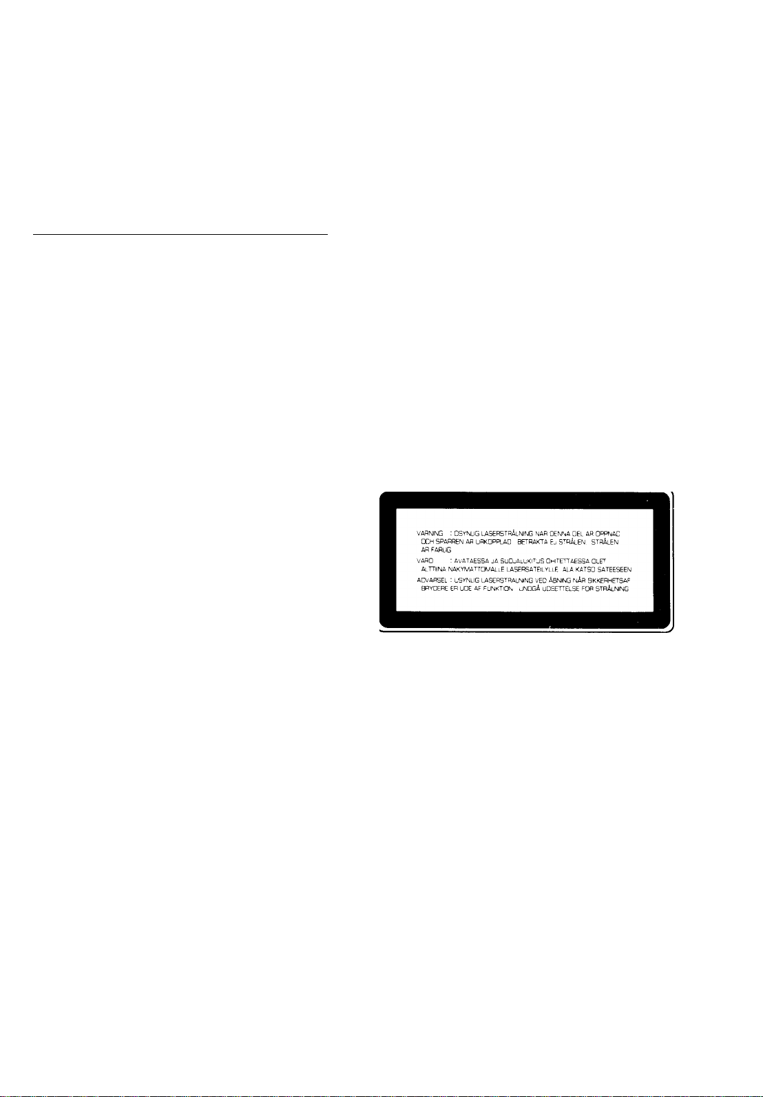
Klassmärkning for Finland
CLASS 1 LASER PRODUCT
LUOKAN 1 LASERLAITE
KLASS 1 LASERAPPARAT
ADVARSEL
Usynlig laserstrâling ved âbning. Undgâ udsaettelse for strâling.
VAROITUS
Laiteen käyttäminen muulla kuin tässä käyttöohjeesa mainitulla
tavalla saattaa altistaa käyttäjän turvallisuusluokan 1 ylittävälle
näkymättömälle lasersäteilylle.
YARNING
Om apparaten används pâ annat sätt än i denna bruksanvisning
specificerats, kan användaren utsättas for osynlig laserstrâlning,
som överskrider gränsen for laserklass 1.

This product complies with the radio frequency interference
requirements of the Council Directive 82/499/EEC and/or 87/
308/EEC.
Get appareil est conforme aux prescriptions de la directive
communautaire 87/308/CEE.
Diese Geräte entsprechen der EG-Richtlinie 82/499/EWG
und/oder 87/308/EWG.
Dette apparat overholder det gaeldende EF-dlrektIv
vedrorende radiostoj.
Questo apparecchio è conforme al D.M.13 aprile 1989
(Direttiva CEE/87/308) sulla soppressione dei radiodisturbi.
Este producto está de acuerdo con los requisitos sobre
Interferencias de radio frequencia fijados por el Consejo
Directivo 87/308 CEE.
Dit product voldoet aan de EEG normen betreffende radio-
frekwentie storingen 82/499/EEG en/of 87/308/EEG.
The YPDR is subject to COCOM regulations,
if you intend exporting this product, you should follow the
necessary procedures to obtain prior approval from the
government of the country from which the YPDR is being
exported.

Table of Contents
1 • Introduction
1.1 Features..............................................................................................................3
1.2 TOC PRE ........................................................................................................... 3
1.3 TOC AFTER .......................................................................................................3
1.4 Applications ........................................................................................................4
2 • Installation and precautions
2.1 Installation...........................................................................................................5
2.2 Head locking system ..........................................................................................5
2.3 General care and maintenance...........................................................................6
2.4 Warm-up and condensation ...............................................................................6
2.5 Care of discs.......................................................................................................6
2.6 Copyright ............................................................................................................7
3 • Main unit (YPDR601)
3.1 Front panel .........................................................................................................8
1 Disc tray..........................................................................................................8
2 OPEN/CLOSE key...........................................................................................8
3 POWER indicator............................................................................................8
4 Cl indicator.......................................................................................................8
5 RECORD indicator..........................................................................................8
6 DISC indicator.................................................................................................8
7 ERROR indicator.............................................................................................9
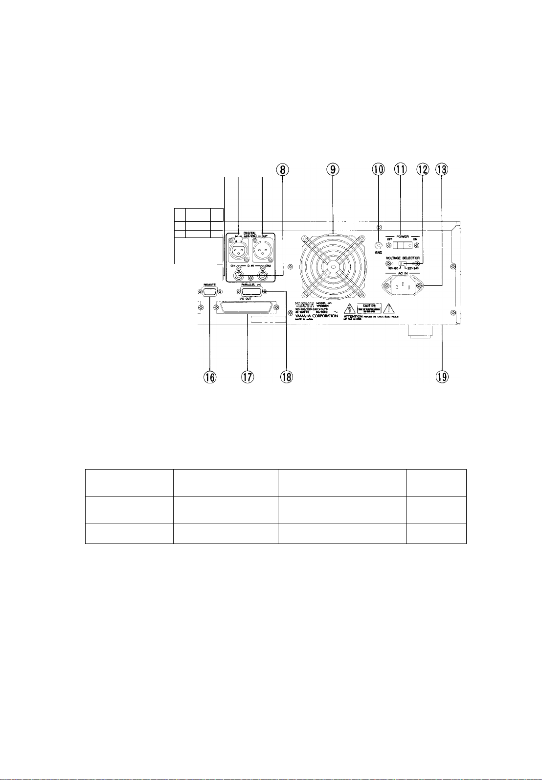
3.2 Rear panel ......................................................................................................... 9
1 HICH/LOW switch...........................................................................................9
2 LEVEL ADJ (Lch, Rch)....................................................................................9
3 ANALOG IN.....................................................................................................9
4 ANALOG OUT.................................................................................................10
5 SYNC (IN, OUT)..............................................................................................10
6 DIGITAL AES/EBU (IN)...................................................................................10
7 DIGITAL AES/EBU (OUT)...............................................................................10
8 D.IN (CHI, CH2).............................................................................................. 10
9 Cooling fan...................................................................................................... 10
10 Ground (earth) terminal.................................................................................10
11 POWER switch..............................................................................................10
12 VOLTAGE SELECTOR.................................................................................10
13 AC IN.............................................................................................................10
14 DRIVE ID switch............................................................................................10
15 I/O IN.............................................................................................................10
16 REMOTE connector
17 I/O OUT...................................................................................................... 11
18 Parallel I/O connector...................................................................................11
19 LOCK/RELEASE.......................................................................................... 11
.....................................................................................
11
4 • Remote controller (RC601)
4.1 Front panel .........................................................................................................12
1 DIGITAL IN/EMPHASIS/COPY PROHIBIT/ALARM indicators
2 Display............................................................................................................ 13
3 Display function indicators
4 INDEX keys.....................................................................................................13
5 DISPLAY.........................................................................................................13
6 LINE................................................................................................................ 13
7 INPUT/REPRO................................................................................................13
8 Meters............................................................................................................. 13
9 Transport controls............................................................................................14
10 TRACK keys..................................................................................................14
11 SEARCH....................................................................................................... 14
12 REHEARSAL
4.2 Rear panel ........................................................................................................15
1 PHONES connector..........................................................................................1 5
................................................................................................
..............................................................................
.......................
12
13
14
YPDR

Table of Contents
2 PHONES LEVEL.............................................................................................15
3 DRIVE SELECT.............................................................................................. 15
4 DIP switch bank.............................................................................................. 15
EMPHASIS..................................................................................................15
PEAK HOLD ................................................................................................15
COPY GUARD
EXT W. SYNC ............................................................................................15
5 INPUT SELECT switches................................................................................16
6 TOC switches..................................................................................................16
7 POWER switch................................................................................................16
8 CONTROL connector......................................................................................16
9 AC IN...............................................................................................................16
...........................................................................................
5 • Connection
5.1 Audio connections .............................................................................................17
5.2 Single-recorder connection ................................................................................17
5.2.1 Analog input level adjustment
5.3 Multi-recorder connection..................................................................................19
...................................................................
6 • Operation
6.1 Playback of previously-recorded CDs...............................................................21
6.1.1 Disc type displays ....................................................................................21
6.1.2 Track and index location
6.1.3 Search mode ............................................................................................22
6.2 Recording fixed tracks (TOC PRE mode)..........................................................22
6.2.1 Recording the TOC .................................................................................. 23
6.2.2 Track start ................................................................................................ 23
6.2.3 Rehearsing an audio recording ................................................................23
Levels .........................................................................................................24
6.2.4 Audio recording ........................................................................................24
REC MUTE..................................................................................................25
STOP/PAUSE .............................................................................................25
AUTO PAUSE..............................................................................................25
6.2.5 Lead-out....................................................................................................25
6.3 Recording variable tracks (TOC AFTER mode)
6.3.1 Track start .................................................................................................26
Minimum track lengths.................................................................................26
6.3.2 Rehearsal .................................................................................................26
6.3.3 Audio recording ........................................................................................26
REC MUTE..................................................................................................27
PAUSE ....................................................................................................... 27
STOP ..........................................................................................................27
6.3.4 Recording the TOC ..................................................................................27
6.4 Multi-recorder recording ....................................................................................27
6.5 Duplication ........................................................................................................28
...........................................................................
................................................
15
18
22
25
7 • Errors
8 • Technical specifications
8.1 Controller (RC601) ...........................................................................................31
8.2 Recorder Unit (YPDR601) ................................................................................ 32
8.3 50-pin I/O connector pinout
8.4 Serial REMOTE (D-sub 9-pin)
8.5 PARALLEL I/O (D-sub 15-pin)...........................................................................34
8.5.1 Parallel I/O timing chart ............................................................................35
YPDR
ii
...............................................................................
..........................................................................
33
33

1 • Introduction - Features
1 • Introduction
The Yamaha Professional Disc Recorder (YPDR) system is composed of two
parts: the YPDR601 Disc Recorder Unit (referred to in this manual as "the main
unit", and the RC601 remote controller (referred to in this manual as "the con
troller". The two are connected using a 5m (16ft) 50-pin cable (supplied).
1.1 Features
The YPDR system allows the recording of discs which may be replayed
on standard CD players.
Up to 99 tracks may be recorded on one disc, and up to 99 index markers
may be written within each track.
Recording of a disc need not be continuous audio data can be written
from different sources (master tapes, etc).
The operation of the YPDR system is similar to the operation of a tape-re
corder, making disc production analogous to the assembly of a master
tape.
Audio sources may be analog or digital (either SDIF-II or AES/EBU format).
Monitoring may be carried out while recording, either of the source or off-
disc. The monitor output may be analog or digital (AES/EBU format).
Up to seven YPDR601 recorder units may be linked together and con
trolled from one controller for parallel recording, or for disc duplication.
The YPDR system provides two recording modes, as described below:
1.2 TOC PRE
In this mode, the YPDR system writes a TOC (Table Of Contents) before any au
dio data has been recorded. A TOC which references 99 tracks is written. All
tracks are the same length, and the length of each track may be set to 10 seconds
or 30 seconds (selectable from the controller).
If the 30 second track length is selected, the total recording time available on a
disc is 49 minutes, 30 seconds, and if the 10 second track length is selected, the
total recording time available on a single disc is 16 minutes, 30 seconds.
In this TOC PRE mode, the TOC is first recorded, and then audio recording is
carried out. The disc may be removed from the YPDR and replayed on a com
mercial CD player. If the disc is not full, recording of further tracks may be car
ried out on the YPDR for subsequent replay on CD players.
1.3 TOC AFTER
This mode varies from the TOC PRE mode in that TOC data is written on the
disc after all audio data has been recorded. This allows for variable track
lengths, but means that the disc cannot be played on standard CD players until
the TOC has been written. The YPDR, however, is capable of replaying audio
data from discs which do not yet have a TOC written to them. Once the TOC
has been written, no further recording of audio data which can be read by a
commercial CD player is possible.
The maximum length of audio data which can be written in the TOC AR ER
mode is 74 minutes, dependent on media.
YPDR
Introduction - 3

1 • Introduction - Applications
1.4 Applications
The YPDR system is suitable for all professional audio applications where
speedy production of a limited quantity of discs is required. Such applications
include:
• Pre-recorded public announcement systems (airports, etc) can use disc
rather than tape.
• Broadcasting stations can store jingles, commercials, etc on disc, rather
than on tape cartridge.
• Radio drama and AV post-production facilities can make up custom disc
libraries of sound effects.
• Recording studios may choose to provide "demo discs" rather than "demo
tapes" for their clients.
YPDR
Introduction - 4
2 • Installation and precautions - Installation
2 • Installation and precautions
The following should be included with each YPDR system:
RC601 Remote Controller..........................................1
YPDR601 Professional Disc Recorder......................1
Power cords ...............................................................2
5m (16ft) 50-way connection cable
Rack-mounting ears for main unit
Terminator block .......................................................1
You will also need a supply of blank discs (available from your Yamaha suppli
er).
.........................
.............................
1
1 set
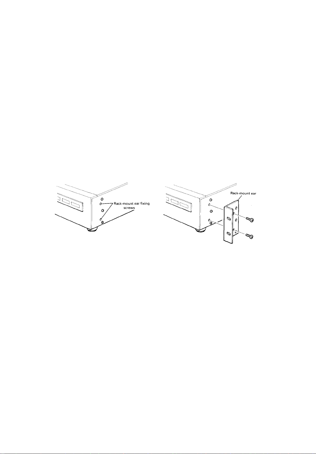
2.1 Installation
The main unit may be rack-mounted (3U of rack space is required) or free-stand
ing. To mount the main unit in a rack, make sure the head is locked, and remove
the feet from the bottom of the unit. Next, remove the fixing screws from the
main unit, and attach the supplied rack-mounting ears, as shown in the illustra
tions below:
There is a voltage selector switch at the rear of the main unit. Two positions are
available: 100-120V and 220-240V (both AC). Make sure that the switch is in
the position corresponding to your local AC voltage.
The controller will accept voltages from 10OVAC to 240VAC. No voltage regu
lation setting is necessary.
As with all pieces of precision electronic equipment, follow the following rules
when using the YPDR: do not subject the equipment to shocks or vibration,
avoid extremes of temperature and humidity, avoid use in a dusty environment,
and allow adequate ventilation when in operation (the main unit is fitted with a
fan make sure that this is not blocked).
2.2 Head locking system
IMPORTANT! The main unit is fitted with a laser head lock system. The head
should be locked whenever the unit is transported or moved, even slightly.
Conversely, the head must be unlocked before the unit is operated.
YPDR
Installation and precautions - 5

2 • Installation and precautions - General care and maintenance
To lock and unlock the head, use the slider on the bottom of the main unit (see
the illustration below):
2.3 General care and maintenance
The YPDR is a precision piece of electronic equipment. Avoid exposing the
YPDR to extremes of temperature or humidity.
Avoid exposing the YPDR to a dusty or smoke-filled environment. Clean the sur
faces of the YPDR with a dry, lint-free cloth. Do not use spray cleaners, thinners
or solvents. A little mild detergent applied to a slightly damp cloth may be used
to remove stubborn stains or grease marks.
There are no user-serviceable parts inside either the main unit or the controller.
Do not disassemble the YPDR. Refer to a Yamaha service center for any repairs
or adjustments.
ALWAYS use the head lock system when transporting or moving the YPDR,
even for a short distance.
When recording, only use blank discs of a type recommended by YAMAHA.
Use of any other kind of disc may not give satisfactory results, and may even
result in damage to the YPDR.
2.4 Warm-up and condensation
The main unit requires 30 minutes after power-on before it can be used. Allow
this amount of time after switching on the unit before attempting recording.
If the main unit is brought into a warm room from a cold environment, internal
condensation may occur. Allow between 1 and 2 hours for the unit to acclima
tize before attempting operation.
2.5 Care of discs
Optical audio discs and CDs are robust storage media, but the rules below
should be followed in order to extend their usable lifetime:
• Do not expose discs to direct sunlight or bright light of any kind, and keep
them away from strong sources of heat. Avoid storage or use in places
which have a high humidity. If the discs become damp, allow them to dry
naturally, or use an air stream to dry them.
• Before using a disc for recording, remove any dust particles, etc. using an
air stream (gently blow). If any dust particles cannot be removed using this
method, clean the disc with a lint-free cloth. Wipe the non-label side of
the disc radially from center to edge. Do not wipe in a circular path. Do
YPDR
Installation and precautions - 6

2 • Installation and precautions - Copyright
not use thinners, alcohol or solvent to clean discs. Allow the discs to dry
naturally, or use an air stream to dry them. Do not use a cloth.
Do not bend or scratch discs. To avoid mechanical damage to discs, al
ways store them in their cases.
When labelling discs, do not stick labels or paper to the disc. Label them
by writing on the label side only with a fiber-tip marker. The use of any
other writing implement may damage the disc.
2.6 Copyright
NOTE
Please check the copyright laws in your country to record from
records, compact discs, radio, etc. Recording of copyright material
may infringe copyright laws.
___________________________________________
YPDR
Installation and precautio.ns - 7
3 • Main unit (YPDR601) - Front panel
3 • Main unit (YPDR601)
The main unit houses the disc transport, recording and replay components, and
the audio connections to the sources and the monitoring system.
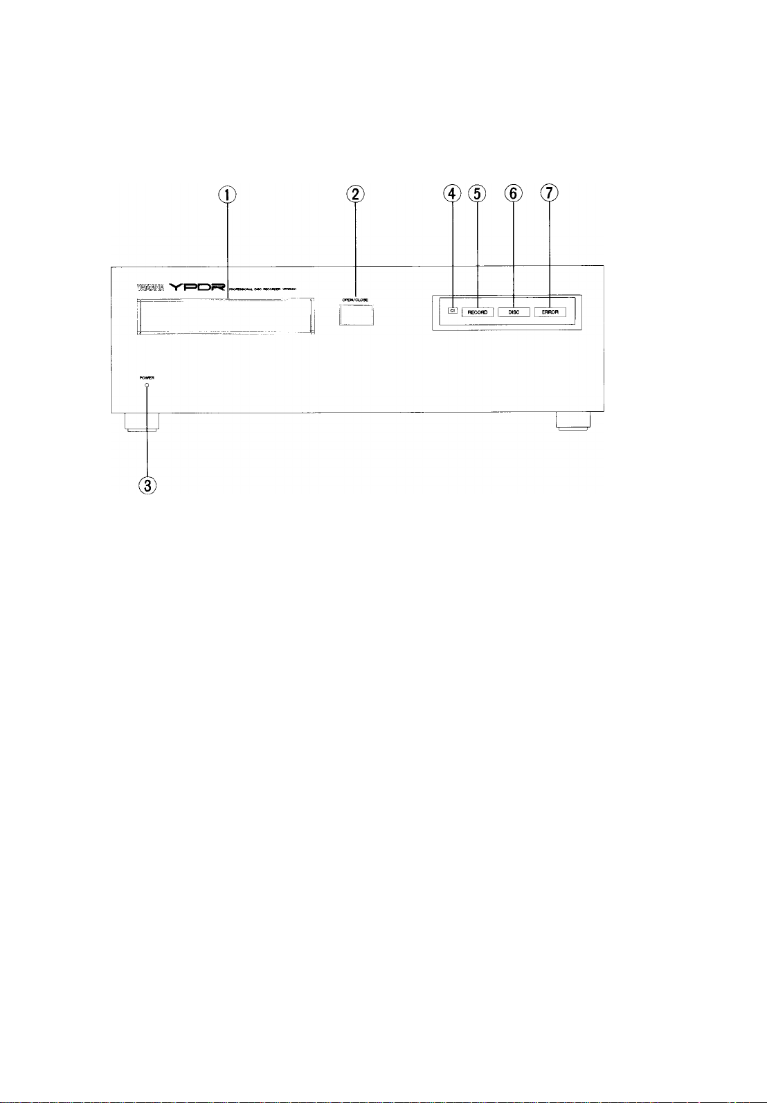
3.1 Front panel
(T) Disc tray
The disc tray holds discs for playing and recording. Discs are placed in the tray
with the label upwards. The tray is opened and closed using the OPEN/CLOSE
key (2).
(2) OPEN/CLOSE key
This key opens and closes the disc tray (1).
(D POWER indicator
When power is applied to the main unit (using the rear panel POWER switch
(11)), this indicator will be lit.
0C1 indicator
This indicator lights briefly when a Cl (single-symbol) error occurs. If many Cl
errors occur together, this indicator will light continuously.
(D RECORD indicator
This indicator lights when either audio or TOC data is being recorded.
(D DISC indicator
This indicator lights steadily when a disc has been inserted into the disc tray, the
disc tray has been closed, and the unit is ready for playback or recording. When
a disc has been inserted in the disc tray, this indicator will flash until the main
unit is ready to start recording or playing back.
YPDR
Main unit (YPDR601) - 8
(7) ERROR indicator
If a non-recoverable error occurs, this indicator will light. Press the Tr INC and
DISPLAY keys on the controller to determine the kind of error which has oc
curred (explained in "Errors" on page 30).
3.2 Rear panel
The rear panel of the main unit is where audio and control connections are
made.
3 • Main unit (YPDR601) - Rear panel
(p(|)
(3)
ANALOS IN
©HIGH/LOW switch
This switch is used with the analog inputs, to allow the matching of the recorder
input circuitry with the analog source. The two positions correspond to:
(4) (D® (7)
@
ANALOG OUT
—
I @ to?
Position
HIGH
LOW -9dBm
Both positions are adjustable ±3dB using the LEVEL ADJ (Lch, Rch) (2).
©LEVEL ADJ (Lch, Rch)
These two trimmer controls allow the fine adjustment of signal levels from the
analog inputs to the recording circuitry. The range is ±3dB from the center po
sition (fully counter-clockwise gives -3dB, fully clockwise gives -i-3dB).
©ANALOG IN
These two XLR-type connectors allow the input of balanced analog signals at
levels determined by the HIGH/LOW switch (1) and LEVEL ADJ (Lch, Rch) (2).
Nominal level Maximum before clipping Impedance
+4dBm
+24dBm lOkQ
+1 IdBm
50kQ
YPDR
Main unit (YPDR50D-9
 Loading...