

Yamaha YP400Z Owner's Manual

Read this manual carefully before operating this vehicle.
OWNER’S MANUAL
LIT-11626-23-11
YP400Z
34B-28199-11
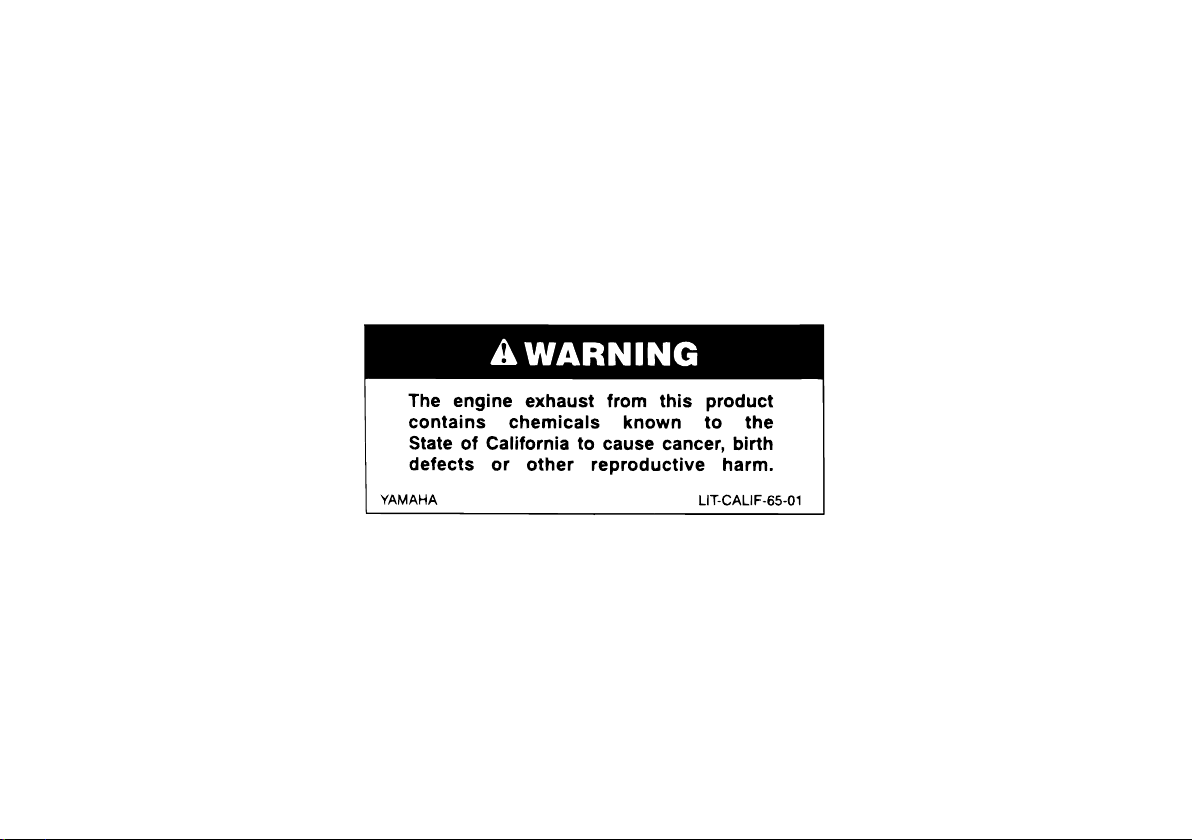
EAU10042
Q
Read this manual carefully before operating this vehicle. This manual should stay with this vehicle if it is sold.
INTRODUCTION
EAU10092
Congratulations on your purchase of the Yamaha YP400Z. This model is the result of Yamaha’s vast experience in the production of fine sporting, touring, and pacesetting racing machines. It represents the high degree of craftsmanship and reliability that have made Yamaha a leader in these fields.
This manual will give you an understanding of the operation, inspection, and basic maintenance of this scooter. If you have
any questions concerning the operation or maintenance of your scooter, please consult a Yamaha dealer.
The design and manufacture of this Yamaha scooter fully comply with the emissions standards for clean air applicable at the
date of manufacture. Yamaha has met these standards without reducing the performance or economy of operation of the
scooter. To maintain these high standards, it is important that you and your Yamaha dealer pay close attention to the recommended maintenance schedules and operating instructions contained within this manual.
Yamaha continually seeks advancements in product design and quality. Therefore, while this manual contains the most current product information available at the time of printing, there may be minor discrepancies between your scooter and this
manual. If there is any question concerning this manual, please consult a Yamaha dealer.
WARNING
Please read this manual and the “YOU AND YOUR MOTORCYCLE: RIDING TIPS” booklet carefully and completely
before operating this scooter. Do not attempt to operate this scooter until you have attained adequate knowledge
of its controls and operating features and until you have been trained in safe and proper riding techniques. Regular
inspections and careful maintenance, along with good riding skills, will ensure that you safely enjoy the capabilities
and reliability of this scooter.
EWA12581
IMPORTANT MANUAL INFORMATION
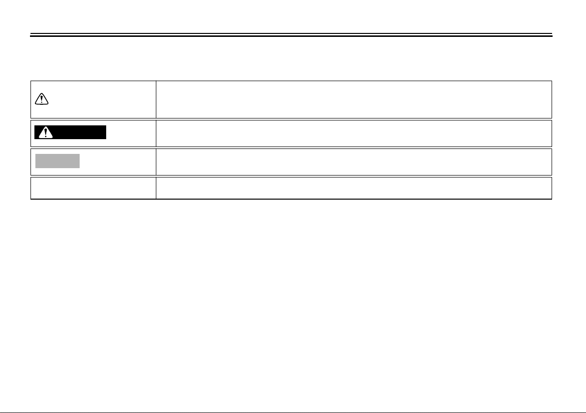
Particularly important information is distinguished in this manual by the following notations:
This is the safety alert symbol. It is used to alert you to potential personal injury
hazards. Obey all safety messages that follow this symbol to avoid possible injury
or death.
EAU10132
WARNING
NOTICE
TIP
A WARNING indicates a hazardous situation which, if not avoided, could result in
death or serious injury.
A NOTICE indicates special precautions that must be taken to avoid damage to the
vehicle or other property.
A TIP provides key information to make procedures easier or clearer.
IMPORTANT MANUAL INFORMATION
YP400Z
OWNER’S MANUAL
©2009 by Yamaha Motor Corporation, U.S.A.
1st edition, February 2009
All rights reserved.
Any reprinting or unauthorized use
without the written permission of
Yamaha Motor Corporation, U.S.A.
is expressly prohibited.
Printed in Japan.
P/N LIT-11626-23-11
EAU10193

TABLE OF CONTENTS
LOCATION OF IMPORTANT
LABELS
SAFETY INFORMATION
Further safe-riding points ................ 2-5
DESCRIPTION
Left view .......................................... 3-1
Right view ........................................ 3-2
Controls and instruments................. 3-3
INSTRUMENT AND CONTROL
FUNCTIONS
Main switch/steering lock ................ 4-1
Indicator and warning lights ............ 4-2
Speedometer .................................. 4-2
Tachometer .................................... 4-3
Multi-function display ...................... 4-3
Handlebar switches ........................ 4-7
Front brake lever ............................ 4-8
Rear brake lever ............................. 4-8
Rear brake lock lever ...................... 4-8
Fuel tank cap .................................. 4-9
Fuel ............................................... 4-10
Catalytic converter ........................ 4-11
Seats ............................................ 4-12
Adjusting the rider seat ................. 4-13
Storage compartments ................. 4-14
Adjusting the shock absorber
Sidestand ...................................... 4-16
............................................. 1-1
.................. 2-1
.................................. 3-1
....................................... 4-1
assemblies ................................ 4-16
Ignition circuit cut-off system ........ 4-17
FOR YOUR SAFETY – PREOPERATION CHECKS
OPERATION AND IMPORTANT
RIDING POINTS
Starting the engine ......................... 6-1
Starting off ...................................... 6-2
Acceleration and deceleration ........ 6-2
Braking ........................................... 6-3
Engine break-in .............................. 6-3
Parking ........................................... 6-4
PERIODIC MAINTENANCE AND
ADJUSTMENT
Owner’s tool kit ............................... 7-2
Periodic maintenance chart for the
emission control system ............. 7-3
General maintenance and
lubrication chart .......................... 7-4
Removing and installing cowlings
and panels .................................. 7-8
Checking the spark plug ............... 7-12
Canister ........................................ 7-14
Engine oil and oil filter element .... 7-14
Final transmission oil .................... 7-17
Coolant ......................................... 7-18
Air filter elements and check
hoses and V-belt case air
filter element ............................. 7-19
................................... 7-1
...................... 5-1
................................. 6-1
Checking the throttle cable free
play ........................................... 7-22
Valve clearance ........................... 7-22
Tires ............................................. 7-23
Cast wheels ................................. 7-24
Front and rear brake lever free
play ........................................... 7-25
Adjusting the rear brake lock
lever cable ................................ 7-26
Checking the front and rear brake
pads .......................................... 7-26
Checking the brake fluid level ...... 7-27
Changing the brake fluid .............. 7-28
Checking and lubricating the
cables ....................................... 7-28
Checking and lubricating the
throttle grip and cable ............... 7-29
Lubricating the front and rear
brake levers .............................. 7-29
Checking and lubricating the
centerstand and sidestand ....... 7-29
Checking the front fork ................. 7-30
Checking the steering .................. 7-31
Checking the wheel bearings ....... 7-31
Battery .......................................... 7-31
Replacing the fuses ..................... 7-33
Replacing a headlight bulb .......... 7-34
Tail/brake light .............................. 7-34
Replacing a front turn signal
light bulb ................................... 7-35

Replacing a rear turn signal light
bulb ........................................... 7-36
Replacing the license plate light
bulb ........................................... 7-36
Troubleshooting ............................ 7-37
Troubleshooting charts ................. 7-38
TABLE OF CONTENTS
SCOOTER CARE AND STORAGE
Matte color caution ......................... 8-1
Care ................................................ 8-1
Storage ........................................... 8-3
SPECIFICATIONS
CONSUMER INFORMATION
Identification numbers .................. 10-1
Reporting safety defects ............... 10-3
Scooter noise regulation ............... 10-4
Maintenance record ...................... 10-5
YAMAHA MOTOR
CORPORATION, U.S.A.
STREET AND ENDURO
MOTORCYCLE LIMITED
WARRANTY .............................. 10-7
YAMAHA EXTENDED SERVICE
(Y.E.S.) ..................................... 10-9
............................. 9-1
........... 10-1
... 8-1
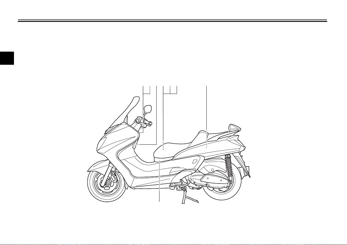
LOCATION OF IMPORTANT LABELS
Read and understand all of the labels on your vehicle. They contain important information for safe and proper operation of
your vehicle. Never remove any labels from your vehicle. If a label becomes difficult to read or comes off, a replacement label
is available from your Yamaha dealer.
1
EAU10383
2
3
1
6
4
5
7
8
1-1
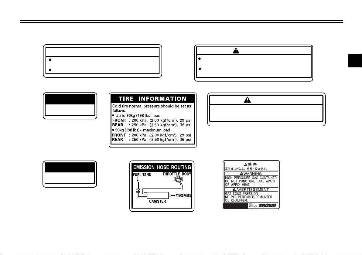
LOCATION OF IMPORTANT LABELS
1
NOTICE
Cleaning with alkaline or acid cleaner,
gasoline
Use
3
or
solvent will damage windshield.
neutral detergent.
4
LOAD LIMIT
2 kg {4 lbs}
5RU-24877-A0
6
LOAD LIMIT
5 kg {11 lbs}
3LD-24877-A0
2
WARNING
8ET—2815K—00
BEFORE YOU OPERATE THIS VEHICLE, READ
THE OWNER’S MANUAL AND ALL LABELS.
ALWAYS WEAR AN APPROVED MOTORCYCLE
HELMET, eye protection, and protective clothing.
5GK-2118K-00
1
2
5
WARNING
3
Improper loading can cause loss of control.
Read owner’s manual for proper loading.
3JJ—28446—A1
5RU-21668-00
7
7
5RU-21686-00
8
4
5
6
7
8
9
1-2

SAFETY INFORMATION
Be a Responsible Owner
As the vehicle’s owner, you are respon-
1
sible for the safe and proper operation
of your scooter.
2
Scooters are single-track vehicles.
Their safe use and operation are de-
3
pendent upon the use of proper riding
techniques as well as the expertise of
the operator. Every operator should
4
know the following requirements before
riding this scooter.
5
He or she should:
●
Obtain thorough instructions from
6
a competent source on all aspects
of scooter operation.
●
7
Observe the warnings and maintenance requirements in this Owner’s Manual.
8
●
Obtain qualified training in safe
and proper riding techniques.
●
9
Obtain professional technical service as indicated in this Owner’s
Manual and/or when made necessary by mechanical conditions.
EAU10263
Safe Riding
Perform the pre-operation checks each
time you use the vehicle to make sure it
is in safe operating condition. Failure to
inspect or maintain the vehicle properly
increases the possibility of an accident
or equipment damage. See page 5-1
for a list of pre-operation checks.
●
This scooter is designed to carry
the operator and a passenger.
●
The failure of motorists to detect
and recognize scooters in traffic is
the predominating cause of automobile/scooter accidents. Many
accidents have been caused by an
automobile driver who did not see
the scooter. Making yourself conspicuous appears to be very effective in reducing the chance of this
type of accident.
Therefore:
●
Wear a brightly colored jacket.
●
Use extra caution when you are
approaching and passing
through intersections, since intersections are the most likely
places for scooter accidents to
occur.
●
Ride where other motorists can
see you. Avoid riding in another
motorist’s blind spot.
●
Many accidents involve inexperienced operators. In fact, many operators who have been involved in
accidents do not even have a current driver’s license.
●
Make sure that you are qualified
and that you only lend your
scooter to other qualified operators.
●
Know your skills and limits.
Staying within your limits may
help you to avoid an accident.
●
We recommend that you practice riding your scooter where
there is no traffic until you have
become thoroughly familiar with
the scooter and all of its controls.
●
Many accidents have been caused
by error of the scooter operator. A
typical error made by the operator
is veering wide on a turn due to excessive speed or undercornering
(insufficient lean angle for the
speed).
2-1
●
Always obey the speed limit and
never travel faster than warranted by road and traffic conditions.
●
Always signal before turning or
changing lanes. Make sure that
other motorists can see you.
●
The posture of the operator and
passenger is important for proper
control.
●
The operator should keep both
hands on the handlebar and
both feet on the operator footrests during operation to maintain control of the scooter.
●
The passenger should always
hold onto the operator, the seat
strap or grab bar, if equipped,
with both hands and keep both
feet on the passenger footrests.
Never carry a passenger unless
he or she can firmly place both
feet on the passenger footrests.
●
Never ride under the influence of
alcohol or other drugs.
●
This scooter is designed for
on-road use only. It is not suitable
for off-road use.
Protective apparel
The majority of fatalities from scooter
accidents are the result of head injuries. The use of a safety helmet is the
single most critical factor in the prevention or reduction of head injuries.
●
Always wear an approved helmet.
●
Wear a face shield or goggles.
Wind in your unprotected eyes
could contribute to an impairment
of vision that could delay seeing a
hazard.
●
The use of a jacket, substantial
shoes, trousers, gloves, etc., is effective in preventing or reducing
abrasions or lacerations.
●
Never wear loose-fitting clothes,
otherwise they could catch on the
control levers or wheels and cause
injury or an accident.
●
Always wear protective clothing
that covers your legs, ankles, and
feet. The engine or exhaust system become very hot during or after operation and can cause burns.
●
A passenger should also observe
the above precautions.
SAFETY INFORMATION
Avoid Carbon Monoxide Poisoning
All engine exhaust contains carbon
monoxide, a deadly gas. Breathing carbon monoxide can cause headaches,
dizziness, drowsiness, nausea, confusion, and eventually death.
Carbon Monoxide is a colorless, odorless, tasteless gas which may be
present even if you do not see or smell
any engine exhaust. Deadly levels of
carbon monoxide can collect rapidly
and you can quickly be overcome and
unable to save yourself. Also, deadly
levels of carbon monoxide can linger
for hours or days in enclosed or poorly
ventilated areas. If you experience any
symptoms of carbon monoxide poisoning, leave the area immediately, get
fresh air, and SEEK MEDICAL TREATMENT.
●
Do not run engine indoors. Even if
you try to ventilate engine exhaust
with fans or open windows and
doors, carbon monoxide can rapidly reach dangerous levels.
●
Do not run engine in poorly ventilated or partially enclosed areas
such as barns, garages, or car-
2
3
4
5
6
7
8
9
2-2
SAFETY INFORMATION
ports.
●
Do not run engine outdoors where
engine exhaust can be drawn into
a building through openings such
1
2
as windows and doors.
Loading
Adding accessories or cargo to your
scooter can adversely affect stability
3
and handling if the weight distribution of
the scooter is changed. To avoid the
possibility of an accident, use extreme
4
caution when adding cargo or accessories to your scooter. Use extra care
5
when riding a scooter that has added
cargo or accessories. Here, along with
6
the information about accessories below, are some general guidelines to follow if loading cargo to your scooter:
7
The total weight of the operator, passenger, accessories and cargo must
8
not exceed the maximum load limit.
Operation of an overloaded vehicle
9
could cause an accident.
Maximum load:
196 kg (432 lb)
When loading within this weight limit,
keep the following in mind:
●
Cargo and accessory weight
should be kept as low and close to
the scooter as possible. Securely
pack your heaviest items as close
to the center of the vehicle as possible and make sure to distribute
the weight as evenly as possible
on both sides of the scooter to minimize imbalance or instability.
●
Shifting weights can create a sudden imbalance. Make sure that accessories and cargo are securely
attached to the scooter before
riding. Check accessory mounts
and cargo restraints frequently.
●
Properly adjust the suspension
for your load (suspension-adjustable models only), and
check the condition and pressure of your tires.
●
Never attach any large or heavy
items to the handlebar, front
fork, or front fender. Such items
can create unstable handling or
a slow steering response.
●
This vehicle is not designed to
pull a trailer or to be attached to
a sidecar.
Genuine Yamaha Accessories
Choosing accessories for your vehicle
is an important decision. Genuine
Yamaha accessories, which are available only from a Yamaha dealer, have
been designed, tested, and approved
by Yamaha for use on your vehicle.
Many companies with no connection to
Yamaha manufacture parts and accessories or offer other modifications for
Yamaha vehicles. Yamaha is not in a
position to test the products that these
aftermarket companies produce.
Therefore, Yamaha can neither endorse nor recommend the use of accessories not sold by Yamaha or
modifications not specifically recommended by Yamaha, even if sold and
installed by a Yamaha dealer.
Aftermarket Parts, Accessories,
and Modifications
While you may find aftermarket products similar in design and quality to
genuine Yamaha accessories, recognize that some aftermarket accessories
2-3

SAFETY INFORMATION
or modifications are not suitable because of potential safety hazards to you
or others. Installing aftermarket products or having other modifications performed to your vehicle that change any
of the vehicle’s design or operation
characteristics can put you and others
at greater risk of serious injury or death.
You are responsible for injuries related
to changes in the vehicle.
Keep the following guidelines in mind,
as well as those provided under “Loading” when mounting accessories.
●
Never install accessories or carry
cargo that would impair the performance of your scooter. Carefully
inspect the accessory before using
it to make sure that it does not in
any way reduce ground clearance
or cornering clearance, limit suspension travel, steering travel or
control operation, or obscure lights
or reflectors.
●
Accessories fitted to the handlebar or the front fork area can
create instability due to improper
weight distribution or aerodynamic changes. If accessories
are added to the handlebar or
front fork area, they must be as
lightweight as possible and
should be kept to a minimum.
●
Bulky or large accessories may
seriously affect the stability of
the scooter due to aerodynamic
effects. Wind may attempt to lift
the scooter, or the scooter may
become unstable in cross
winds. These accessories may
also cause instability when
passing or being passed by
large vehicles.
●
Certain accessories can displace the operator from his or
her normal riding position. This
improper position limits the freedom of movement of the operator and may limit control ability,
therefore, such accessories are
not recommended.
●
Use caution when adding electrical accessories. If electrical accessories exceed the capacity of the
scooter’s electrical system, an
electric failure could result, which
could cause a dangerous loss of
lights or engine power.
Aftermarket Tires and Rims
The tires and rims that came with your
scooter were designed to match the
performance capabilities and to provide
the best combination of handling, braking, and comfort. Other tires, rims, sizes, and combinations may not be
appropriate. Refer to page 7-23 for tire
specifications and more information on
replacing your tires.
2
3
4
5
6
7
8
9
2-4
SAFETY INFORMATION
Further safe-riding points
●
Be sure to signal clearly when
making turns.
●
1
2
3
4
5
6
7
8
9
Braking can be extremely difficult
on a wet road. Avoid hard braking,
because the scooter could slide.
Apply the brakes slowly when
stopping on a wet surface.
●
Slow down as you approach a cor-
ner or turn. Once you have com-
pleted a turn, accelerate slowly.
●
Be careful when passing parked
cars. A driver might not see you
and open a door in your path.
●
Railroad crossings, streetcar rails,
iron plates on road construction
sites, and manhole covers be-
come extremely slippery when
wet. Slow down and cross them
with caution. Keep the scooter up-
right, otherwise it could slide out
from under you.
●
The brake pads could get wet
when you wash the scooter. After
washing the scooter, check the
brakes before riding.
●
Always wear a helmet, gloves,
trousers (tapered around the cuff
EAU10372
and ankle so they do not flap), and
a bright colored jacket.
●
Do not carry too much luggage on
the scooter. An overloaded scooter is unstable. Use a strong cord to
secure any luggage to the carrier
(if equipped). A loose load will affect the stability of the scooter and
could divert your attention from the
road. (See page 2-1.)
2-5
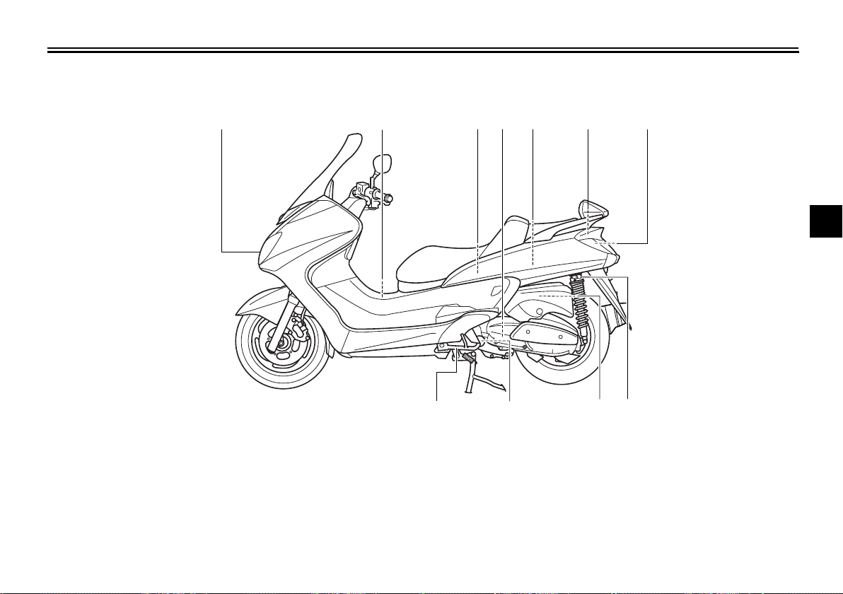
Left view
DESCRIPTION
EAU10410
1
1. Headlight (page 7-34)
2. Fuel tank cap (page 4-9)
3. Rear storage compartment (page 4-14)
4. V-belt case air filter element (page 7-19)
5. Owner’s tool kit (page 7-2)
6. Fuses (page 7-33)
7. Battery (page 7-31)
2 3
11 9
8. Shock absorber assembly spring preload adjusting ring (page 4-16)
9. Air filter element (left) (page 7-19)
10.Engine oil filter element (page 7-14)
11.Sidestand (page 4-16, 7-29)
4
10
5
67
2
3
4
5
6
7
8
8
9
3-1
DESCRIPTION
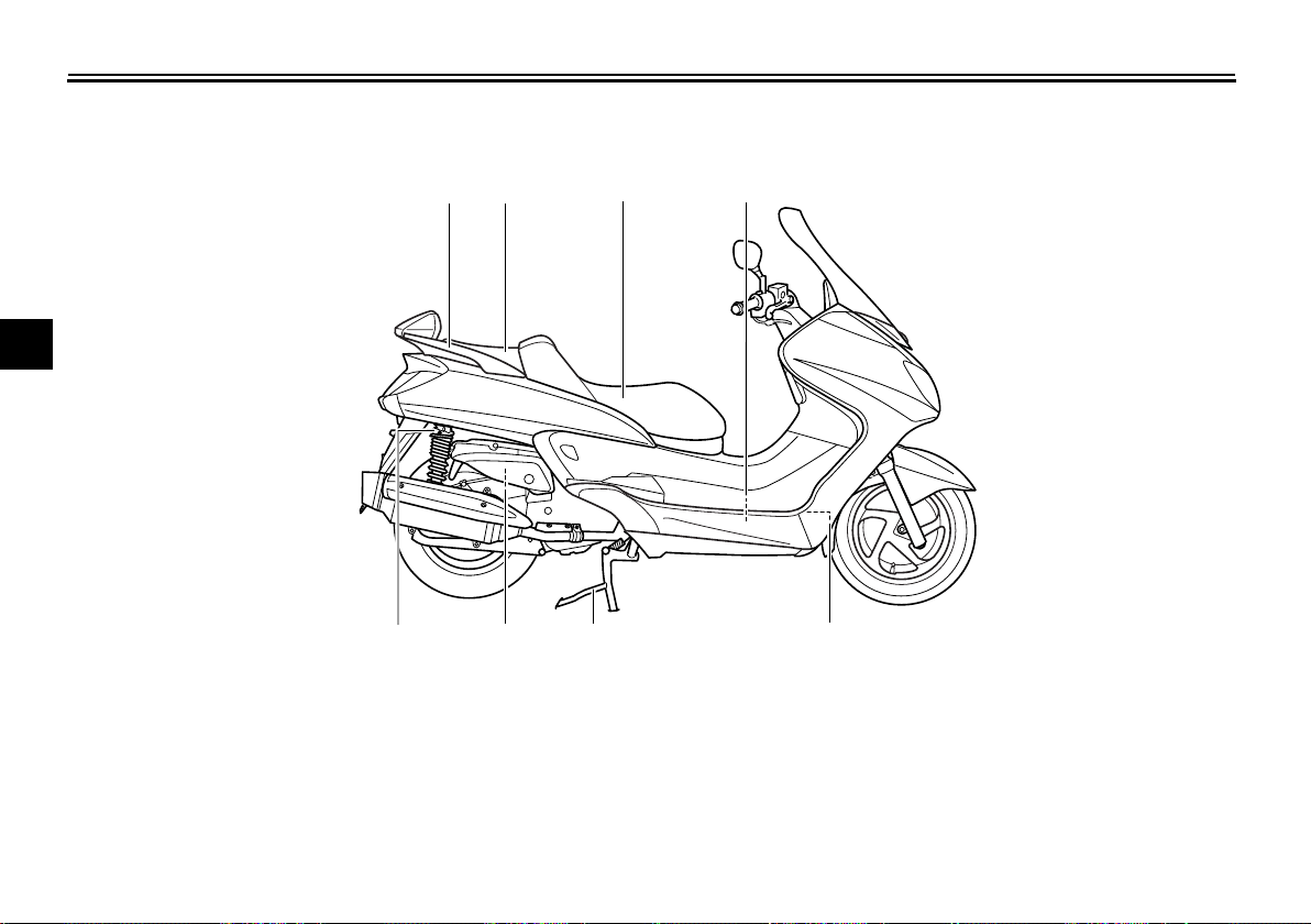
Right view
EAU10420
1
2
3
4
5
6
7
8
1. Grab bar (page 6-2)
2. Passenger seat (page 4-12)
9
3. Rider seat (page 4-12)
4. Coolant reservoir (page 7-18)
5. Radiator
6. Centerstand (page 7-29)
7. Air filter element (right) (page 7-19)
2
1
3
7 68
4
5
8. Shock absorber assembly spring preload adjusting ring (page 4-16)
3-2
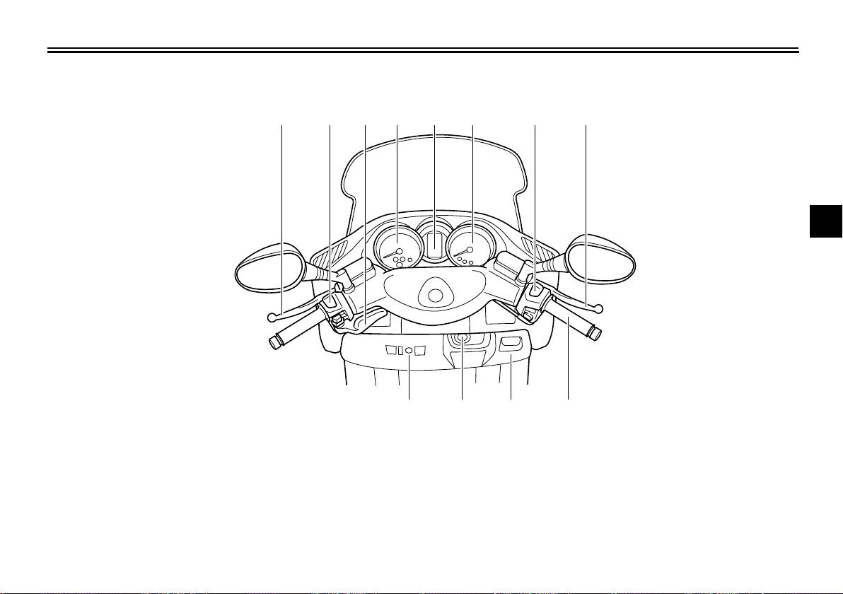
Controls and instruments
DESCRIPTION
EAU10430
1. Rear brake lever (page 4-8)
2. Left handlebar switches (page 4-7)
3. Rear brake lock lever (page 4-8)
4. Speedometer (page 4-2)
5. Multi-function display (page 4-3)
6. Tachometer (page 4-3)
7. Right handlebar switches (page 4-7)
1345678
2
9101112
8. Front brake lever (page 4-8)
9. Throttle grip (page 7-22)
10.Front storage compartment B (page 4-14)
11.Main switch/steering lock (page 4-1)
12.Front storage compartment A (page 4-14)
2
3
4
5
6
7
8
9
3-3
INSTRUMENT AND CONTROL FUNCTIONS
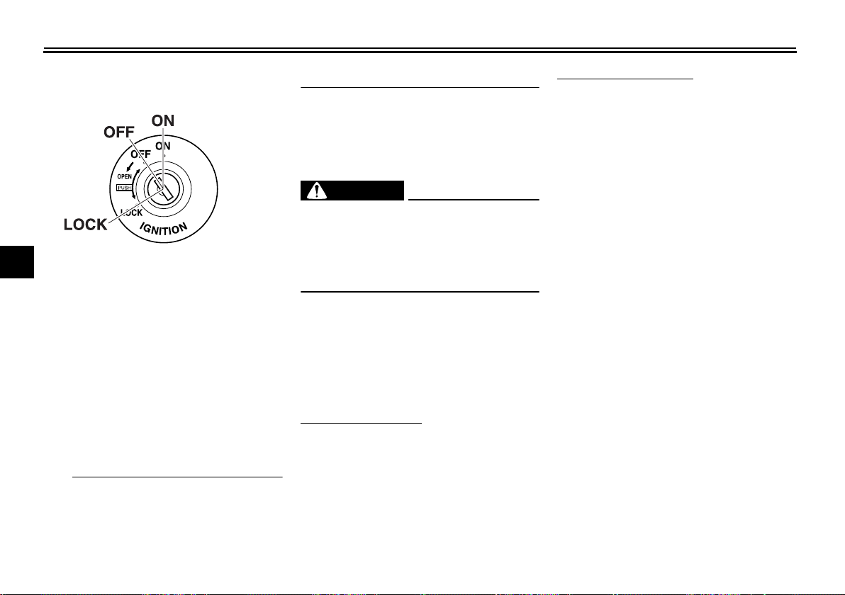
Main switch/steering lock
1
2
3
4
The main switch/steering lock controls
the ignition and lighting systems, and is
5
used to lock the steering. The various
positions are described below.
6
ON
7
All electrical circuits are supplied with
power; the meter lighting, taillight, license plate light and position lights
8
come on, and the engine can be started. The key cannot be removed.
9
TIP
The headlights come on automatically
when the engine is started and stay on
until the key is turned to “OFF” or the
EAU10460
EAU36070
sidestand is moved down.
EAU10661
OFF
All electrical systems are off. The key
can be removed.
EWA10061
WARNING
Never turn the key to “OFF” or
“LOCK” while the vehicle is moving.
Otherwise the electrical systems will
be switched off, which may result in
loss of control or an accident.
EAU10681
LOCK
The steering is locked, and all electrical
systems are off. The key can be removed.
To lock the steering
1. Turn the handlebars all the way to
the left.
2. Push the key in from the “OFF” position, and then turn it to “LOCK”
while still pushing it.
3. Remove the key.
To unlock the steering
Push the key in, and then turn it to
“OFF” while still pushing it.
4-1
INSTRUMENT AND CONTROL FUNCTIONS
1
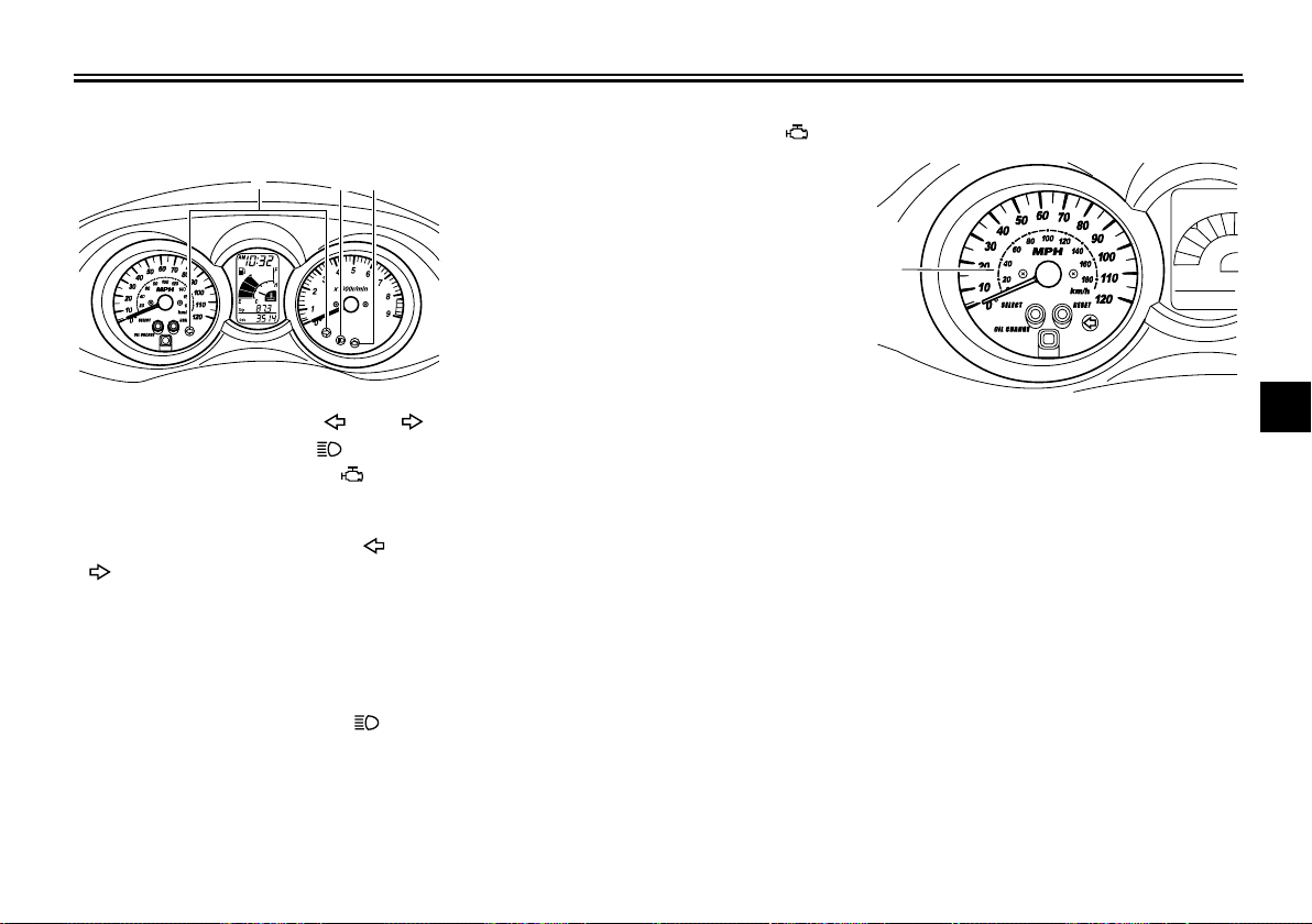
Indicator and warning lights
123
1. Turn signal indicator lights “ ” and “ ”
2. High beam indicator light “ ”
3. Engine trouble warning light “ ”
Turn signal indicator lights “ ” and
“”
The corresponding indicator light flashes when the turn signal switch is
pushed to the left or right.
High beam indicator light “ ”
This indicator light comes on when the
high beam of the headlight is switched
on.
EAU11004
EAU11030
EAU11080
EAU11484
Engine trouble warning light “ ”
This warning light comes on if a problem is detected in the electrical circuit
monitoring the engine. If this occurs,
have a Yamaha dealer check the
self-diagnosis system.
The electrical circuit of the warning light
can be checked by turning the key to
“ON”. The warning light should come
on for a few seconds, and then go off.
If the warning light does not come on
initially when the key is turned to “ON”,
or if the warning light remains on, have
a Yamaha dealer check the electrical
circuit.
EAU11601
Speedometer
1. Speedometer
The speedometer shows the riding
speed.
When the key is turned to “ON”, the
speedometer needle will sweep once
across the speed range and then return
to zero in order to test the electrical circuit.
2
3
4
5
6
7
8
9
4-2
INSTRUMENT AND CONTROL FUNCTIONS
12
3
4
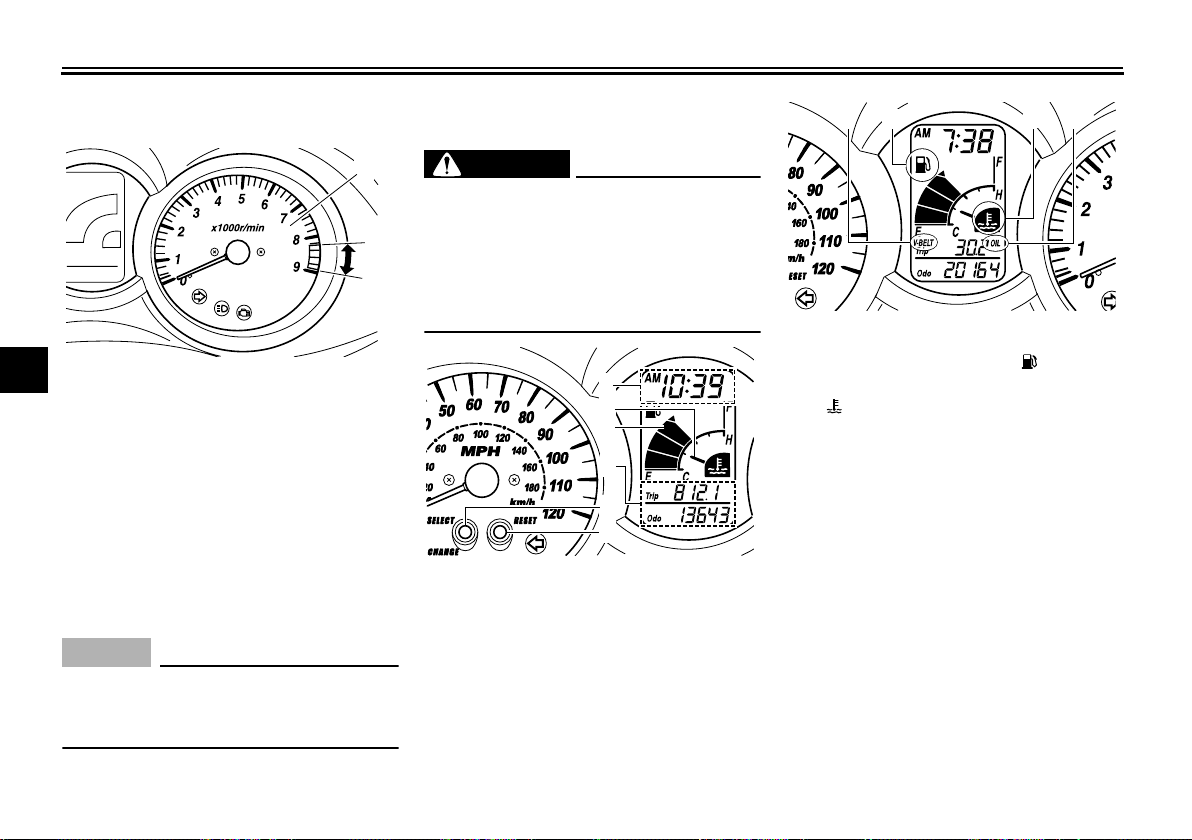
Tachometer
1
2
3
4
1. Tachometer
2. Tachometer red zone
5
The electric tachometer allows the rider
to monitor the engine speed and keep it
6
within the ideal power range.
When the key is turned to “ON”, the ta-
7
chometer needle will sweep once
across the r/min range and then return
to zero r/min in order to test the electri-
8
cal circuit.
9
NOTICE
Do not operate the engine in the tachometer red zone.
Red zone: 8250 r/min and above
EAU11872
1
2
ECA10031
EAU36109
Multi-function display
EWA12312
WARNING
Be sure to stop the vehicle before
making any setting changes to the
multi-function display. Changing
settings while riding can distract the
operator and increase the risk of an
accident.
1
2
3
4
5
6
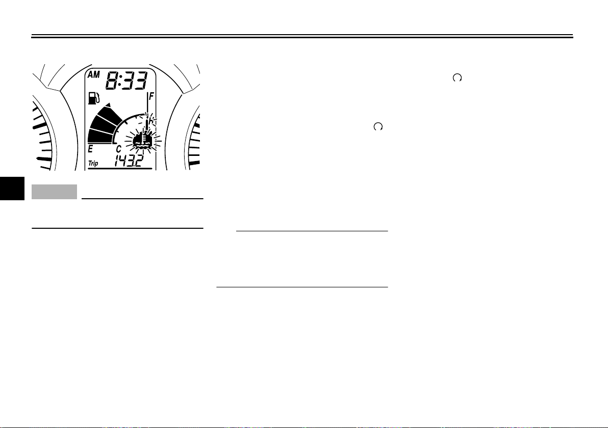
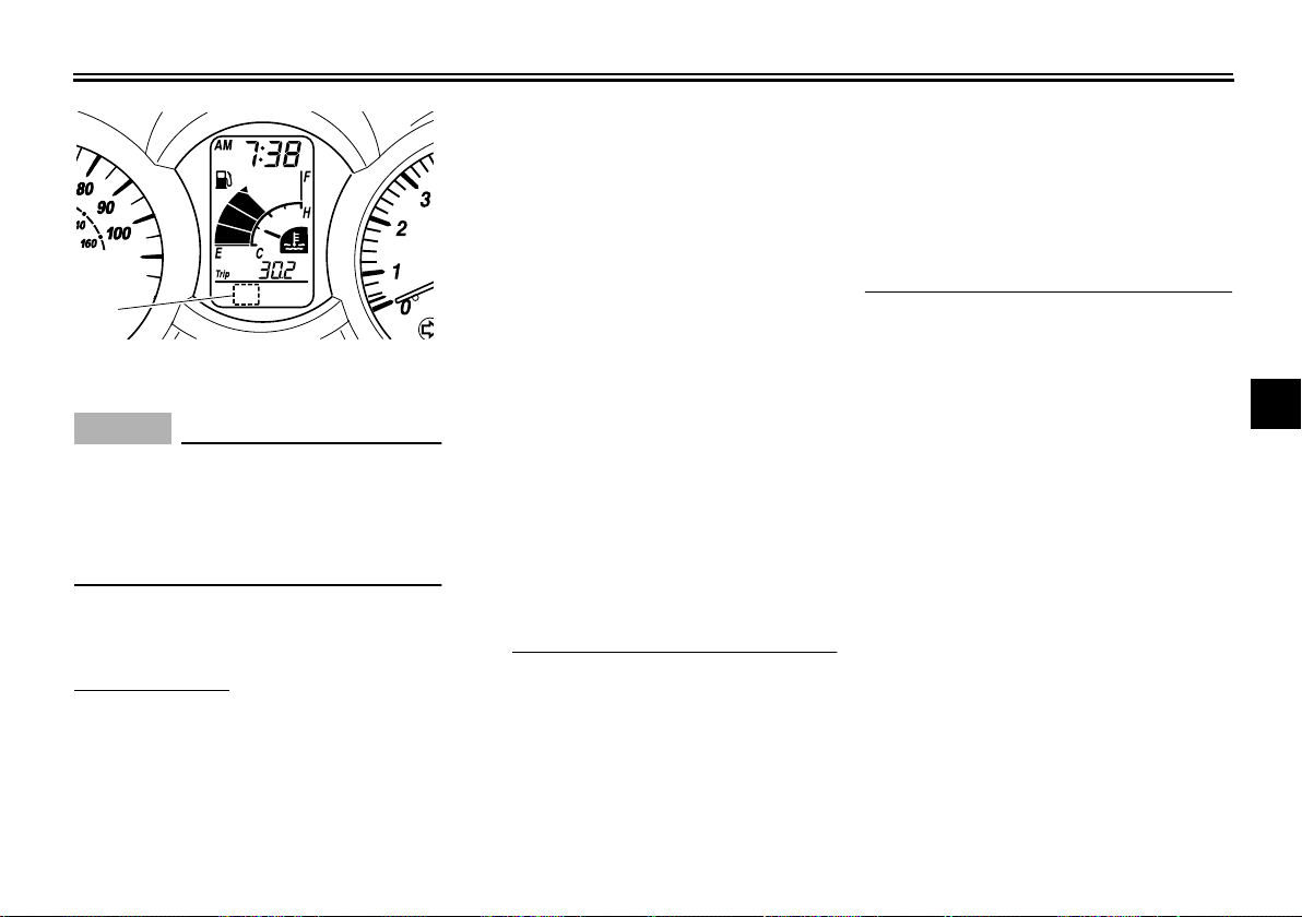
1. Clock/ambient temperature display
2. Coolant temperature meter
3. Fuel meter
4. Odometer/tripmeters
5. “SELECT” button
6. “RESET” button
1. V-belt replacement indicator “V-BELT”
2. Fuel level warning indicator “ ”
3. Coolant temperature warning indicator
“”
4. Oil change indicator “OIL”
The multi-function display is equipped
with the following:
●
a fuel meter
●
a coolant temperature meter
●
an odometer
●
two tripmeters (which show the
distance traveled since they were
last set to zero)
●
a fuel reserve tripmeter (which
shows the distance traveled since
the bottom segment of the fuel
meter and fuel level warning indicator started flashing)
4-3
●
a self-diagnosis device
●
a clock
●
an ambient temperature display
●
an oil change indicator
●
a V-belt replacement indicator
TIP
Be sure to turn the key to “ON” be-
●
fore using the “SELECT” and
“RESET” buttons.
When the key is turned to “ON”, all
●
of the display segments of the
multi-function display will appear
one after the other and then disappear, in order to test the electrical
circuit.
Odometer and tripmeter modes
Pushing the “SELECT” button switches
the display between the odometer
mode “Odo” and the tripmeter modes
“Trip” in the following order:
Odo → Trip (top) → Trip (bottom)
→
Odo
When approximately 2.8 L (0.74 US
gal, 0.62 Imp.gal) of fuel remains in the
fuel tank, the bottom segment of the
fuel meter and fuel level warning indicator will start flashing, and the display will
INSTRUMENT AND CONTROL FUNCTIONS
automatically change to the fuel reserve tripmeter mode “Trip F” and start
counting the distance traveled from that
point. In that case, pushing the
“SELECT” button switches the display
between the various tripmeter and
odometer modes in the following order:
Trip F → Trip (top) → Trip (bottom)
Odo → Trip F
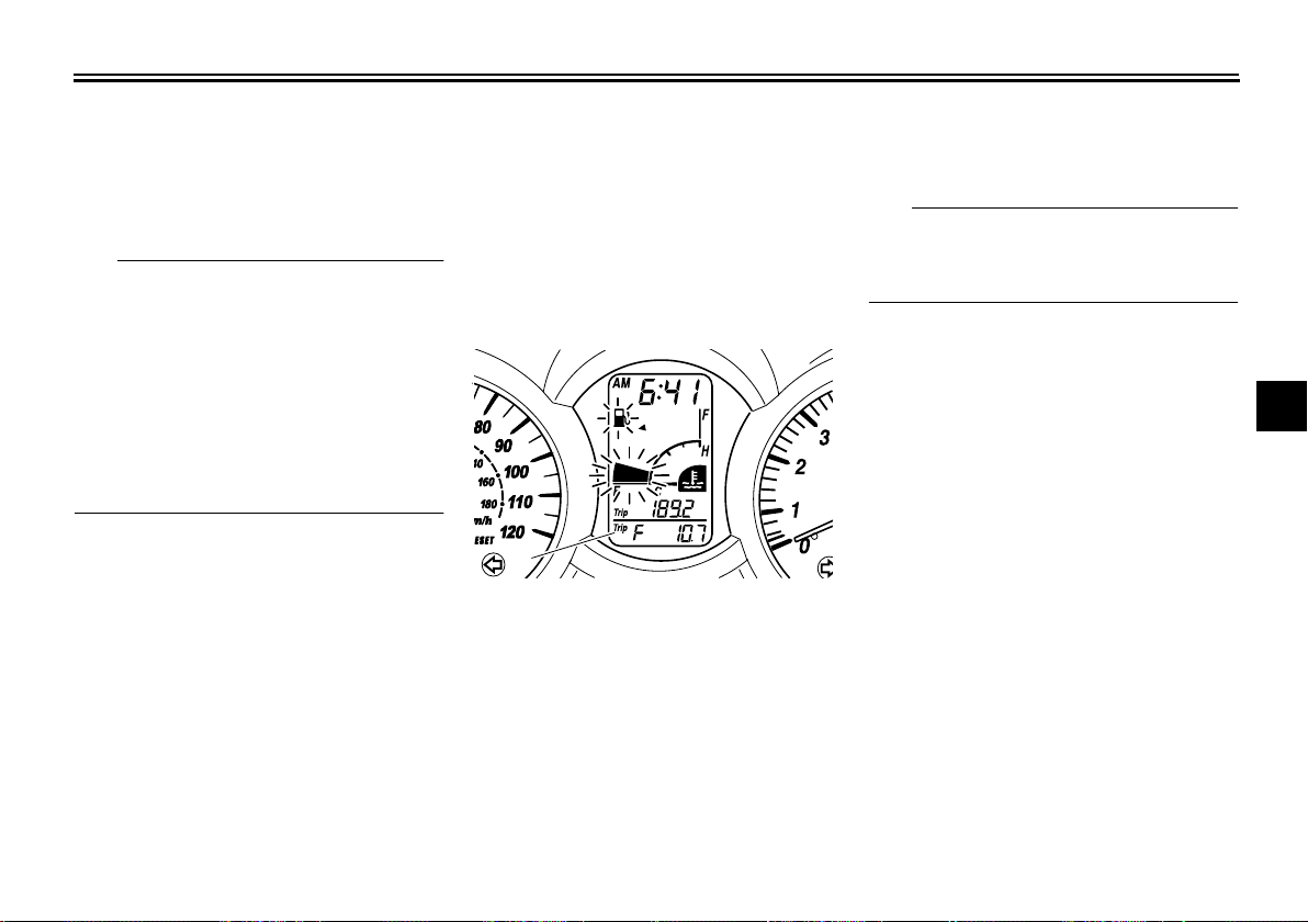
1
1. Fuel reserve tripmeter
To reset a tripmeter, select it by pushing the “SELECT” button until “Trip” or
“Trip F” begins flashing (“Trip” or “Trip
F” will only flash for five seconds).
While “Trip” or “Trip F” is flashing, push
the “RESET” button for at least one
second. If you do not reset the fuel reserve tripmeter manually, it will reset it-
4-4
self automatically and the display will
return to the prior mode after refueling
and traveling 5 km (3 mi).
TIP
The display cannot be changed back to
“Trip F” after pushing the “RESET” button.
→
Fuel meter
With the key in the “ON” position, the
fuel meter indicates the amount of fuel
in the fuel tank. The display segments
of the fuel meter disappear towards “E”
(Empty) as the fuel level decreases.
When the fuel level reaches the bottom
segment near “E”, the fuel level warning indicator and the bottom segment
will flash. Refuel as soon as possible.
Coolant temperature meter
With the key in the “ON” position, the
coolant temperature meter indicates
the temperature of the coolant. The
coolant temperature varies with changes in the weather and engine load. If
the top segment and coolant temperature warning indicator flash, stop the
vehicle and let the engine cool. (See
2
3
4
5
6
7
8
9
INSTRUMENT AND CONTROL FUNCTIONS
page 7-38.)
1
2
3
4
NOTICE
Do not continue to operate the en-
5
gine if it is overheating.
6
Oil change indicator “OIL”
This indicator flashes at the initial 1000
km (600 mi), then at 5000 km (3000 mi)
7
and every 5000 km (3000 mi) thereafter
to indicate that the engine oil should be
8
changed.
After changing the engine oil, reset the
9
oil change indicator. (See page 7-14.)
If the engine oil is changed before the
oil change indicator comes on (i.e. before the periodic oil change interval has
been reached), the indicator must be
ECA10021
reset after the oil change for the next
periodic oil change to be indicated at
the correct time. (See page 7-14.)
The electrical circuit of the indicator can
be checked according to the following
procedure.
1. Set the engine stop switch to “ ”
and turn the key to “ON”.
2. Check that the indicator comes on
for a few seconds and then goes
off.
3. If the indicator does not come on,
have a Yamaha dealer check the
electrical circuit.
TIP
The oil change indicator may flash
when the engine is revved with the
scooter on the centerstand, but this
does not indicate a malfunction.
V-belt replacement indicator
“V-BELT”
This indicator flashes every 20000 km
(12500 mi) when the V-belt needs to be
replaced.
The electrical circuit of the indicator can
be checked according to the following
procedure.
4-5
1. Turn the key to “ON” and make
sure that the engine stop switch is
set to “ ”.
2. If the indicator does not come on,
have a Yamaha dealer check the
electrical circuit.
Self-diagnosis device
This model is equipped with a self-diagnosis device for various electrical circuits.
If a problem is detected in any of those
circuits, the multi-function display will
indicate an error code.
If the multi-function display indicates an
error code, note the code number, and
then have a Yamaha dealer check the
vehicle.
INSTRUMENT AND CONTROL FUNCTIONS
1
1. Error code display
ECA11790
NOTICE
If the multi-function display indicates an error code, the vehicle
should be checked as soon as possible in order to avoid engine damage.
Clock mode
To set the clock:
1. Push the “SELECT” button and
“RESET” button together for at
least two seconds.
2. When the hour digits start flashing,
push the “RESET” button to set the
hours.
3. Push the “SELECT” button, and
the minute digits will start flashing.
4. Push the “RESET” button to set
the minutes.
5. Push the “SELECT” button and
then release it to start the clock.
Pushing the “SELECT” button for
at least two seconds switches the
clock display to the ambient temperature display.
Ambient temperature display
This display shows the ambient temperature from –10 °C (14 °F) to 50 °C
(122 °F) in 1 °C or 1 °F increments. The
temperature displayed may vary from
the ambient temperature. Pushing the
“SELECT” button for at least two seconds switches the ambient temperature
display to the clock display.
TIP
If the ambient temperature falls be-
●
low –10 °C (14 °F), a lower temperature than –10 °C (14 °F) will
not be displayed.
If the ambient temperature climbs
●
above 50 °C (122 °F), a higher
temperature than 50 °C (122 °F)
will not be displayed.
●
The accuracy of the temperature
reading may be affected when
riding slowly (approximately under
20 km/h (12.5 mi/h)) or when
stopped at traffic signals, railroad
crossings, etc.
2
3
4
5
6
7
8
9
4-6
INSTRUMENT AND CONTROL FUNCTIONS
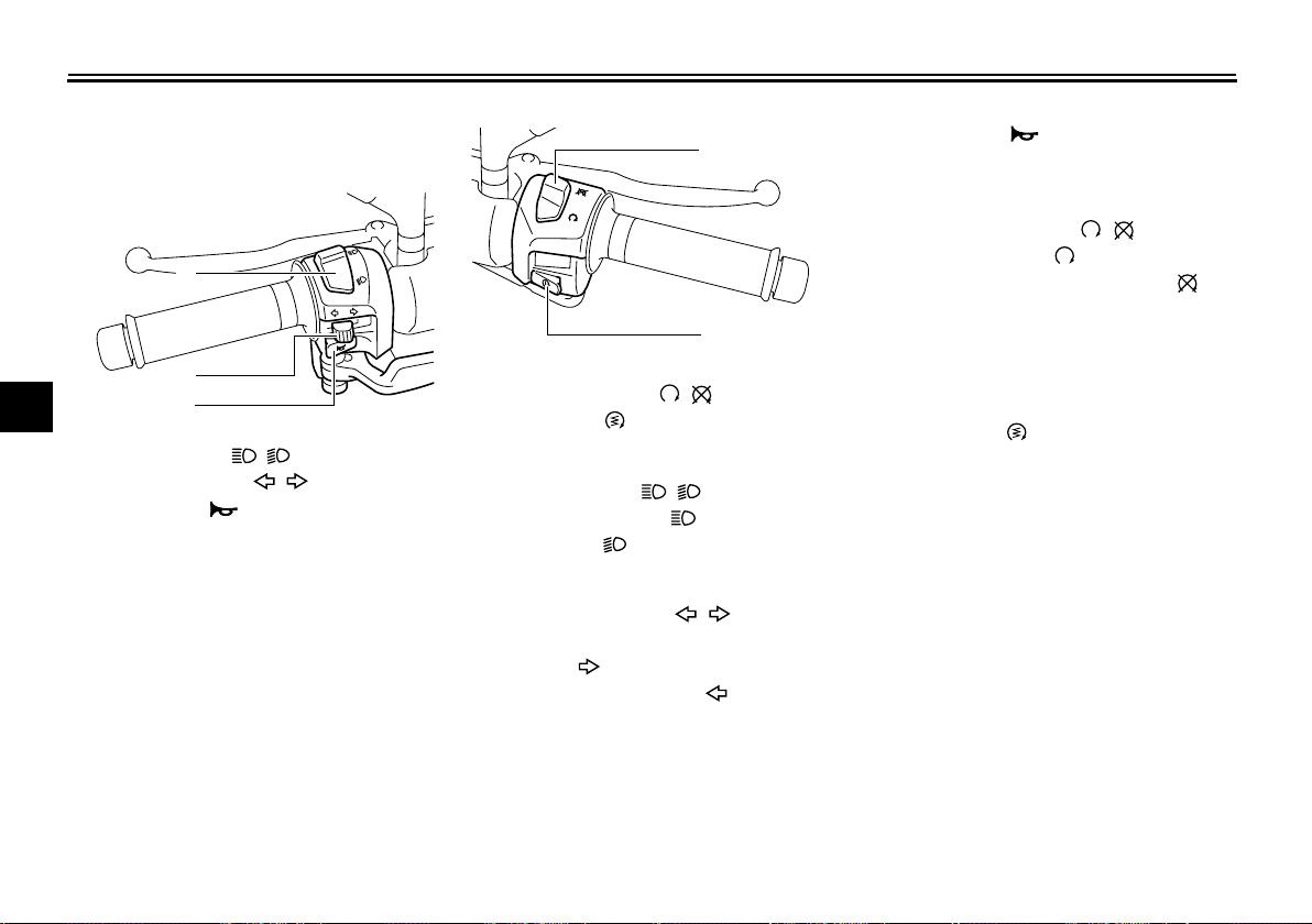
Handlebar switches
Left
1
2
3
4
1. Dimmer switch “ / ”
5
2. Turn signal switch “ / ”
3. Horn switch “ ”
6
7
8
9
1
2
3
EAU12348
Right
1
2
1. Engine stop switch “ / ”
2. Start switch “ ”
EAU12400
Dimmer switch “ / ”
Set this switch to “ ” for the high
beam and to “ ” for the low beam.
EAU12460
Turn signal switch “ / ”
To signal a right-hand turn, push this
switch to “ ”. To signal a left-hand
turn, push this switch to “ ”. When released, the switch returns to the center
position. To cancel the turn signal
lights, push the switch in after it has returned to the center position.
EAU12500
Horn switch “ ”
Press this switch to sound the horn.
EAU12660
Engine stop switch “ / ”
Set this switch to “ ” before starting
the engine. Set this switch to “ ” to
stop the engine in case of an emergency, such as when the vehicle overturns
or when the throttle cable is stuck.
EAU12721
Start switch “ ”
With the sidestand up, push this switch
while applying the front or rear brake to
crank the engine with the starter. See
page 6-1 for starting instructions prior
to starting the engine.
4-7
INSTRUMENT AND CONTROL FUNCTIONS
1
EAU12900
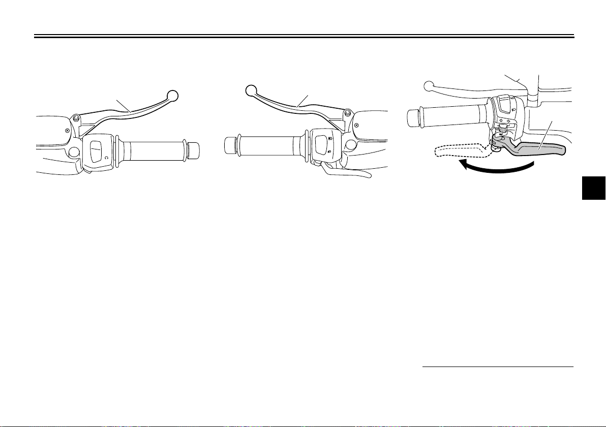
Front brake lever
1
1. Front brake lever
The front brake lever is located on the
right handlebar grip. To apply the front
brake, pull this lever toward the handlebar grip.
EAU12950
Rear brake lever
1
1. Rear brake lever
The rear brake lever is located on the
left handlebar grip. To apply the rear
brake, pull this lever toward the handlebar grip.
EAU12962
Rear brake lock lever
1. Rear brake lock lever
This vehicle is equipped with a rear
brake lock lever to prevent the rear
wheel from moving while stopped at
traffic signals, railroad crossings, etc.
To lock the rear wheel
Push the rear brake lock lever to the left
until it snaps into place.
To unlock the rear wheel
Push the rear brake lock lever back to
the original position.
TIP
Be sure to check that the rear
●
wheel does not move when the
2
3
4
5
6
7
8
9
4-8
INSTRUMENT AND CONTROL FUNCTIONS
1
1
rear brake lock lever is applied.
●
To provide secure locking of the
rear wheel, apply the rear brake lever first before moving the rear
1
2
brake lock lever to the left.
WARNING
Never move the rear brake lock lever
to the left while the vehicle is mov-
3
ing, otherwise loss of control or an
accident may result. Make sure that
4
the vehicle is stopped before moving the rear brake lock lever to the
5
left.
6
7
8
9
EWA12361
Fuel tank cap
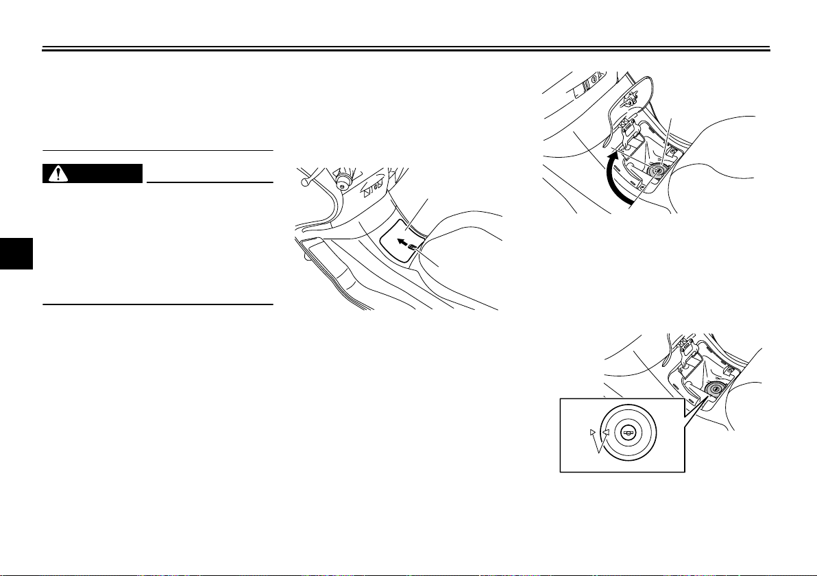
To open the fuel tank cap
1. Open the lid by sliding the lever
forward, and then pull the lever up.
1
2
1. Lid
2. Opening lever
2. Insert the key into the lock and turn
it clockwise. The lock will be released and the fuel tank cap can
be removed.
EAU13163
1. Fuel tank cap
To install the fuel tank cap
1. Align the match marks, insert the
fuel tank cap into the tank opening,
and then push down on the cap.
1. Match marks
2. Turn the key counterclockwise to
4-9
INSTRUMENT AND CONTROL FUNCTIONS
2
1
the original position, and then remove it.
3. Close the lid.
WARNING
Be sure that the fuel tank cap is
properly installed and locked before
riding the scooter. Leaking fuel is a
fire hazard.
EWA11121
EAU13212
Fuel
Make sure there is sufficient gasoline in
the tank.
EWA10881
WARNING
Gasoline and gasoline vapors are
extremely flammable. To avoid fires
and explosions and to reduce the
risk of injury when refueling, follow
these instructions.
1. Before refueling, turn off the engine and be sure that no one is sitting on the vehicle. Never refuel
while smoking, or while in the vicinity of sparks, open flames, or
other sources of ignition such as
the pilot lights of water heaters and
clothes dryers.
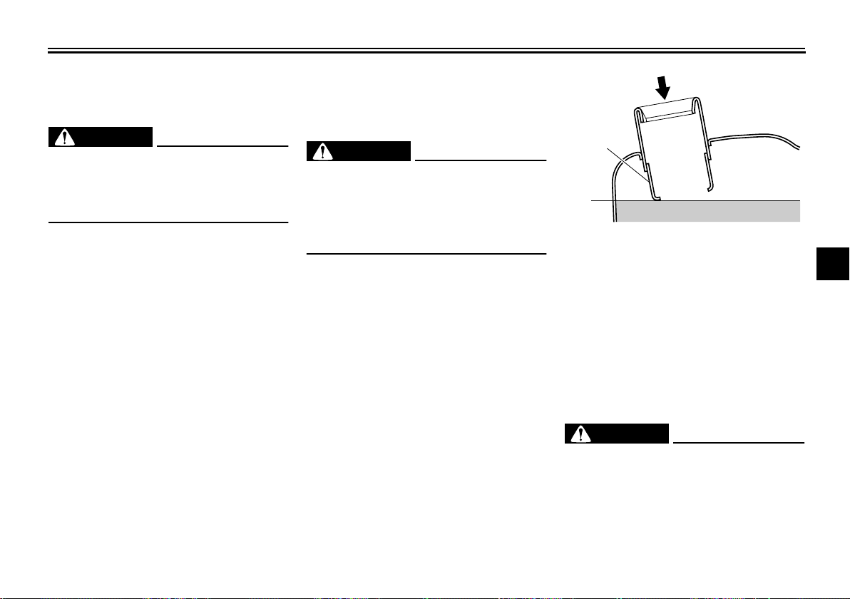
2. Do not overfill the fuel tank. Stop
filling when the fuel reaches the
bottom of the filler tube. Because
fuel expands when it heats up,
heat from the engine or the sun
can cause fuel to spill out of the
fuel tank.
1. Fuel tank filler tube
2. Fuel level
3. Wipe up any spilled fuel immediately.
NOTICE:
Immediately wipe
off spilled fuel with a clean, dry,
soft cloth, since fuel may deteriorate painted surfaces or plastic
parts.
[ECA10071]
4. Be sure to securely close the fuel
tank cap.
EWA15151
WARNING
Gasoline is poisonous and can
cause injury or death. Handle gasoline with care. Never siphon gasoline by mouth. If you should swallow
some gasoline or inhale a lot of gasoline vapor, or get some gasoline in
2
3
4
5
6
7
8
9
4-10
INSTRUMENT AND CONTROL FUNCTIONS
your eyes, see your doctor immediately. If gasoline spills on your skin,
wash with soap and water. If gasoline spills on your clothing, change
1
your clothes.
2
3
4
5
Recommended fuel
UNLEADED GASOLINE ONLY
Fuel tank capacity:
14.0 L (3.70 US gal, 3.08 Imp.gal)
NOTICE
Use only unleaded gasoline. The use
6
of leaded gasoline will cause severe
damage to internal engine parts,
such as the valves and piston rings,
7
as well as to the exhaust system.
Your Yamaha engine has been de-
8
signed to use regular unleaded gasoline with a pump octane number
9
[(R+M)/2] of 86 or higher, or a research
octane number of 91 or higher. If
knocking (or pinging) occurs, use a
gasoline of a different brand or premium unleaded fuel. Use of unleaded fuel
EAU36081
ECA11400
will extend spark plug life and reduce
maintenance costs.
Gasohol
There are two types of gasohol: gasohol containing ethanol and that containing methanol. Gasohol containing
ethanol can be used if the ethanol content does not exceed 10% (E10). Gasohol containing methanol is not
recommended by Yamaha because it
can cause damage to the fuel system
or vehicle performance problems.
EAU13433
Catalytic converter
This model is equipped with a catalytic
converter in the exhaust system.
WARNING
The exhaust system is hot after operation. To prevent a fire hazard or
burns:
●
Do not park the vehicle near
possible fire hazards such as
grass or other materials that
easily burn.
Park the vehicle in a place
●
where pedestrians or children
are not likely to touch the hot
exhaust system.
Make sure that the exhaust sys-
●
tem has cooled down before doing any maintenance work.
Do not allow the engine to idle
●
more than a few minutes. Long
idling can cause a build-up of
heat.
NOTICE
Use only unleaded gasoline. The use
of leaded gasoline will cause unre-
EWA10862
ECA10701
4-11
INSTRUMENT AND CONTROL FUNCTIONS
1
1
pairable damage to the catalytic
converter.
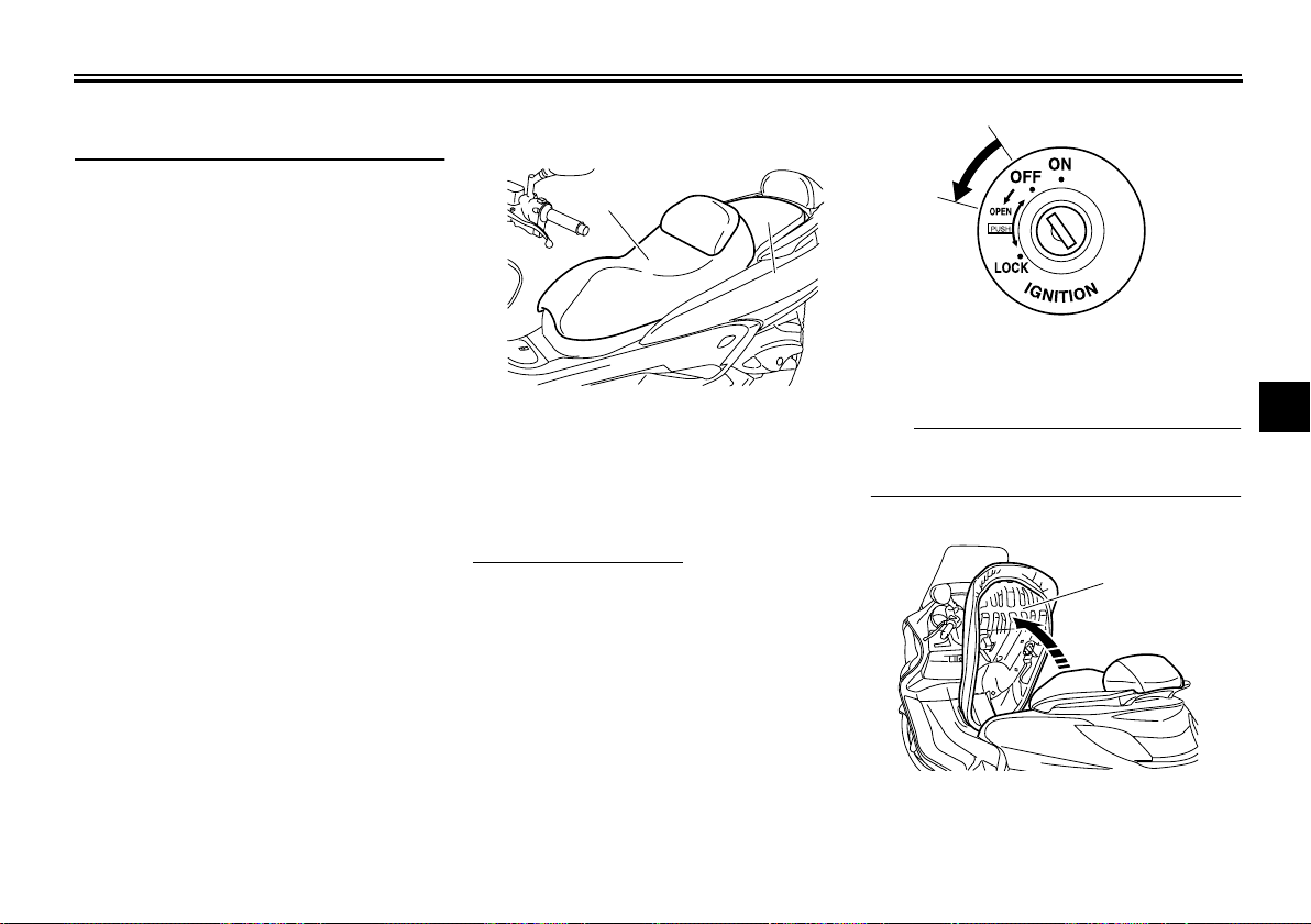
Seats
1
2
1. Rider seat
2. Passenger seat
Rider seat
To open the rider seat
1. Place the scooter on the centerstand.
2. Insert the key into the main switch,
and then turn it counterclockwise.
EAU34140
1. Open.
TIP
Do not push inward when turning the
key.
3. Fold the rider seat up.
2
3
4
5
6
7
8
9
4-12
1. Rider seat
INSTRUMENT AND CONTROL FUNCTIONS
1
To close the rider seat
1. Fold the rider seat down, and then
push it down to lock it in place.
2. Remove the key from the main
1
switch if the scooter will be left unattended.
TIP
2
Make sure that the rider seat is properly
secured before riding.
3
Passenger seat
4
To remove the passenger seat
5
1. Open the rider seat.
2. Remove the bolt, and then pull the
6
7
passenger seat forward.
1
2
8
9
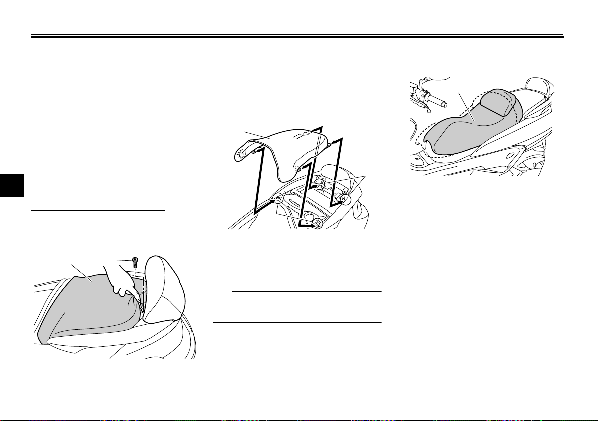
To install the passenger seat
1. Insert the projections on the passenger seat into the holders as
shown, place the passenger seat
in the original position, and then install the bolt.
1
2
2
1. Passenger seat
2. Seat holder
2. Close the rider seat.
TIP
Make sure that the passenger seat is
properly secured before riding.
EAU34150
Adjusting the rider seat
1. Rider seat
The rider seat can be adjusted as follows to change the riding position.
1. Open the rider seat. (See
page 4-12.)
2. Remove the bolts.
1. Passenger seat
2. Bolt
4-13
 Loading...