


SERVICE MANUAL
XJR1300(W)
5WM-28197-E0
2007


EAS20040
XJR1300(W) 2007
SERVICE MANUAL
©2007 by Yamaha Motor Co., Ltd.
First edition, February 2007
All rights reserved.
Any reproduction or unauthorized use
without the written permission of
Yamaha Motor Co., Ltd.
is expressly prohibited.

EAS20070
NOTICE
This manual was produced by the Yamaha Motor Company, Ltd. primarily for use by Yamaha dealers
and their qualified mechanics. It is not possible to include all the knowledge of a mechanic in one manual. Therefore, anyone who uses this book to perform maintenance and repairs on Yamaha vehicles
should have a basic understanding of mechanics and the techniques to repair these types of vehicles.
Repair and maintenance work attempted by anyone without this knowledge is likely to render the vehicle unsafe and unfit for use.
Yamaha Motor Company, Ltd. is continually striving to improve all of its models. Modifications and significant changes in specifications or procedures will be forwarded to all authorized Yamaha dealers and
will appear in future editions of this manual where applicable.
NOTE:
Designs and specifications are subject to change without notice.
EAS20080
IMPORTANT MANUAL INFORMATION
Particularly important information is distinguished in this manual by the following.
The Safety Alert Symbol means ATTENTION! BECOME ALERT! YOUR SAFETY IS
INVOLVED!
Failure to follow WARNING instructions could result in severe injury or death to the
vehicle operator, a bystander or a person checking or repairing the vehicle.
A CAUTION indicates special precautions that must be taken to avoid damage to the
vehicle.
A NOTE provides key information to make procedures easier or clearer.
WARNING
CAUTION:
NOTE:
EAS20090
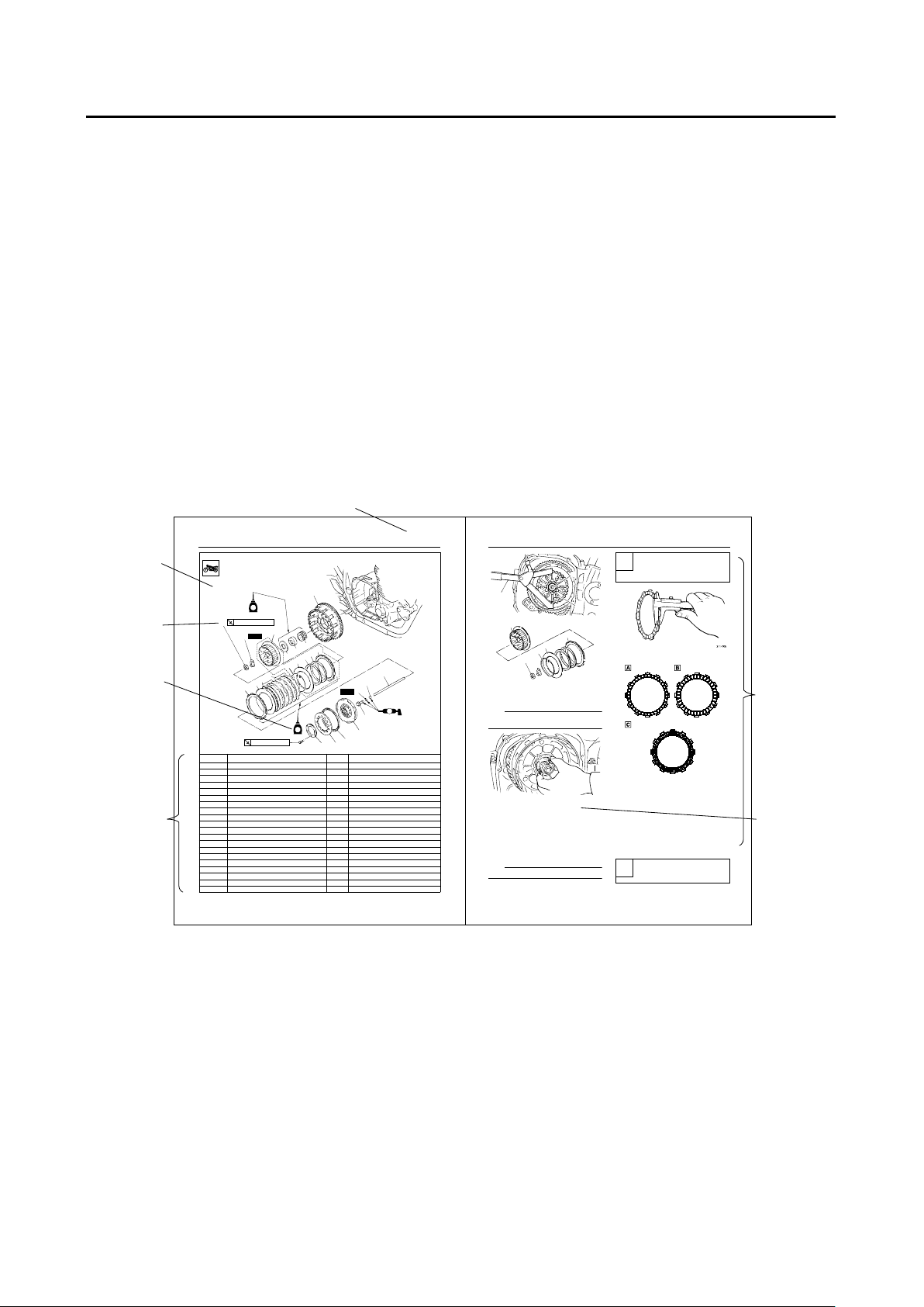
HOW TO USE THIS MANUAL
This manual is intended as a handy, easy-to-read reference book for the mechanic. Comprehensive
explanations of all installation, removal, disassembly, assembly, repair and check procedures are laid
out with the individual steps in sequential order.
●
The manual is divided into chapters and each chapter is divided into sections. The current section title
is shown at the top of each page “1”.
●
Sub-section titles appear in smaller print than the section title “2”.
●
To help identify parts and clarify procedure steps, there are exploded diagrams at the start of each
removal and disassembly section “3”.
●
Numbers are given in the order of the jobs in the exploded diagram. A number indicates a disassembly step “4”.
●
Symbols indicate parts to be lubricated or replaced “5”.
Refer to “SYMBOLS”.
●
A job instruction chart accompanies the exploded diagram, providing the order of jobs, names of
parts, notes in jobs, etc “6”.
●
Jobs requiring more information (such as special tools and technical data) are described sequentially
“7”.
CLUTCH
5-42
3. Remove:
Spacer “1”
Bearing
NOTE:
Insert M6 bolts “2” into the spacer and then remove the spacer by pulling on the bolts.
EAS25100
CHECKING THE FRICTION PLATES
The following procedure applies to inspection of
all friction plates.
1. Check:
Friction plate
Damage/wear Replace.
2. Measure:
friction plate thickness
Out of specification Replace.
NOTE:
Measure the friction plate at four places.
EAS25110
CHECKING THE CLUTCH PLATES
The following procedure applies to inspection of
clutch plates.
1. Check:
Clutch plate
Damage Replace.
2. Measure:
clutch plate warpage
(with a plate surface and thickness gauge “1”)
Over warpage limit Replace.
2
3
1
1
6
3
4
5
1
2
Friction plate thickness
2.903.10 mm (0.1140.122 in)
Wear limit
2.80 mm (0.1102 in)
Warpage limit
0.10 mm (0.0039 in)
CLUTCH
5-36
Removing the clutch
Order Job/Part Q’ty Remarks
1 Pressure plate2 1
2 Clutch spring 1
3 Clutch spring seat 1
4 Pressure plate1 1
5 short clutch push rod 1
6 Ball 1
7 long clutch push rod 1
8 O-ring 1
9 Friction plate 1 inarrowj 1
10 Clutch plate 6
11 Friction plate 2 3
12 Friction plate 3 3
13 clutch boss nut 1
14 Lock washer 1
15 Clutch boss 1
16 Ring 1
17 Clutch plate 1
18 Spring 1
19 Spring seat plate 1
20 Friction plate 1 inarrowj 1
New
New
T
R
.
.
8 Nm (0.8 kg ·
m)
B
4
T
R
.
.
70 Nm (7.0 kg ·
m)
4
13
14
15
24
21
22
23
20
19
18
17
16
11
10
9
1
2
3
4
5
8
6
7
12
3
4
5
6
7
1
2
EAS20100
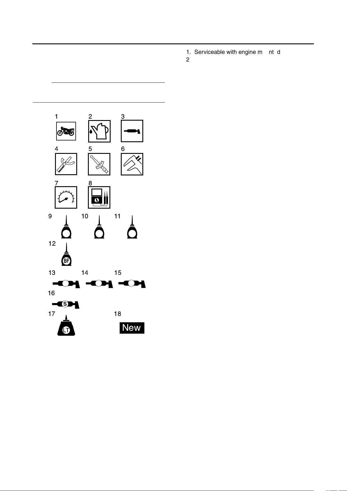
SYMBOLS
The following symbols are used in this manual
for easier understanding.
NOTE:
The following symbols are not relevant to every
vehicle.
G
M
E
B
LS
M
91011
13 14 15
17 18
LT
New
T
R
.
.
123
456
78
BF
12
S
16
1. Serviceable with engine mounted
2. Filling fluid
3. Lubricant
4. Special tool
5. Tightening torque
6. Wear limit, clearance
7. Engine speed
8. Electrical data
9. Engine oil
10. Gear oil
11. Molybdenum-disulfide oil
12. Brake fluid
13. Wheel-bearing grease
14. Lithium-soap-based grease
15. Molybdenum-disulfide grease
16. Silicon grease
17. Apply locking agent (LOCTITE®)
18. Replace the part

EAS20110
TABLE OF CONTENTS
GENERAL INFORMATION
SPECIFICATIONS
PERIODIC CHECKS AND
ADJUSTMENTS
CHASSIS
ENGINE
1
2
3
4
5
FUEL SYSTEM
ELECTRICAL SYSTEM
TROUBLESHOOTING
6
7
8


GENERAL INFORMATION
IDENTIFICATION .......................................................................................... 1-1
VEHICLE IDENTIFICATION NUMBER ................................................... 1-1
MODEL LABEL........................................................................................ 1-1
FEATURES.................................................................................................... 1-2
OUTLINE OF THE FI SYSTEM............................................................... 1-2
FI SYSTEM.............................................................................................. 1-3
IMMOBILIZER SYSTEM ......................................................................... 1-4
INSTRUMENT FUNCTION ..................................................................... 1-5
IMPORTANT INFORMATION ....................................................................... 1-8
PREPARATION FOR REMOVAL AND DISASSEMBLY......................... 1-8
REPLACEMENT PARTS......................................................................... 1-8
GASKETS, OIL SEALS AND O-RINGS .................................................. 1-8
LOCK WASHERS/PLATES AND COTTER PINS ................................... 1-8
BEARINGS AND OIL SEALS .................................................................. 1-8
CIRCLIPS ................................................................................................ 1-9
CHECKING THE CONNECTIONS ................................................................ 1-10
SPECIAL TOOLS .......................................................................................... 1-11
1
2
3
4
5
6
7
8
9
IDENTIFICATION
1-1
EAS20130
IDENTIFICATION
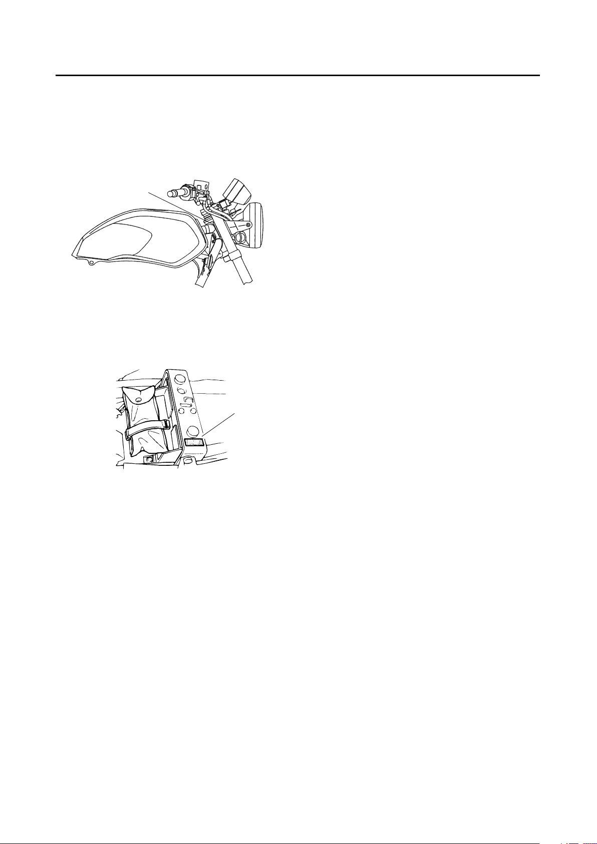
EAS20140
VEHICLE IDENTIFICATION NUMBER
The vehicle identification number “1” is stamped
into the right side of the steering head pipe.
EAS20150
MODEL LABEL
The model label “1” is affixed to the frame. This
information will be needed to order spare parts.
1
1
FEATURES
1-2
EAS20170
FEATURES
EAS5UXB014
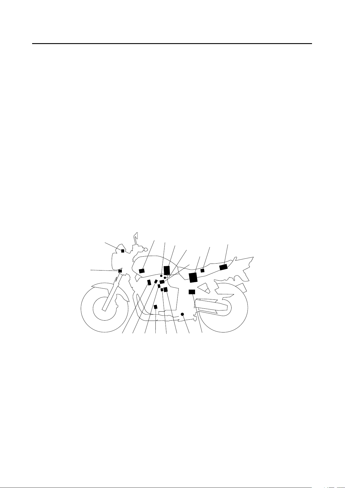
OUTLINE OF THE FI SYSTEM
The main function of a fuel supply system is to provide fuel to the combustion chamber at the optimum
air-fuel ratio in accordance with the engine operating conditions and the atmospheric temperature. In
the conventional carburetor system, the air-fuel ratio of the mixture that is supplied to the combustion
chamber is created by the volume of the intake air and the fuel that is metered by the jet used in the
respective carburetor.
Despite the same volume of intake air, the fuel volume requirement varies by the engine operating conditions, such as acceleration, deceleration, or operating under a heavy load. Carburetors that meter the
fuel through the use of jets have been provided with various auxiliary devices, so that an optimum
air-fuel ratio can be achieved to accommodate the constant changes in the operating conditions of the
engine.
As the requirements for the engine to deliver more performance and cleaner exhaust gases increase,
it becomes necessary to control the air-fuel ratio in a more precise and finely tuned manner. To accommodate this need, this model has adopted an electronically controlled fuel injection (FI) system, in place
of the conventional carburetor system. This system can achieve an optimum air-fuel ratio required by
the engine at all times by using a microprocessor that regulates the fuel injection volume according to
the engine operating conditions detected by various sensors.
The adoption of the FI system has resulted in a highly precise fuel supply, improved engine response,
better fuel economy, and reduced exhaust emissions.
1
2
3
4
5
6
7
8
9
10
11
121314
15
161718
1. Intake air temperature sensor
2. Engine trouble warning light
3. Ignition coil
4. Intake air pressure sensor 1
5. Fuel pump
6. Intake air pressure sensor 2
7. Throttle position sensor
8. Battery
9. Lean angle sensor
10. ECU
11. EXUP servomotor
12. O
2
sensor
13. ISC (idle speed control valve)
14. Crankshaft position sensor
15. Sub-throttle position sensor
16. Engine temperature sensor bolt
17. Fuel injector
18. Spark plug
FEATURES
1-3
EAS5UXB016
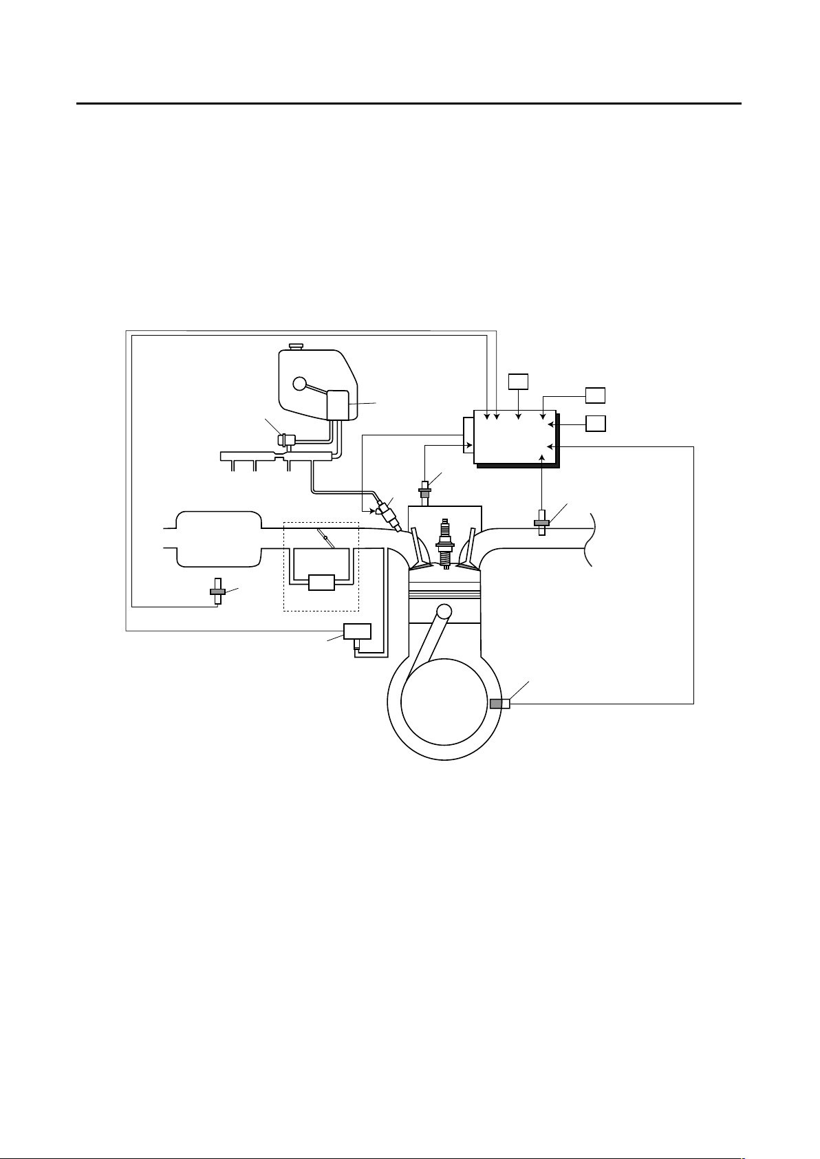
FI SYSTEM
The fuel pump delivers fuel to the fuel injector via the fuel filter. The pressure regulator is installed in
the fuel rail, and maintains the fuel pressure that is applied to the fuel injector at 387 – 397 kPa
(3.87 – 3.97 kg/cm
2
). The fuel injector is operated due to signals from the ECU, and injects fuel into the
intake manifold. Since fuel is supplied only for the duration of injection, good fuel economy is obtained.
The injection duration and the injection timing are controlled by the ECU. Signals that are input from
the throttle position sensor, crankshaft position sensor, intake air pressure sensor, intake temperature
sensor O
2
sensor and engine temperature sensor enable the ECU to determine the injection duration.
The injection timing is determined through the signals from the crankshaft position sensor. As a result,
the volume of fuel that is required by the engine can be supplied at all times in accordance with the
driving conditions.
1
13
12
B
11
10
9
8
A
2
7
3
C
5
4
6
#3#1 #2 #4
14
1. Fuel pump
2. Injector
3. ECU
4. Throttle position sensor
5. Sub-throttle position sensor
6. ISC (idle speed control valve)
7. O
2
sensor
8. Engine temperature sensor
9. Crankshaft position sensor
10. Intake air pressure sensor
11. Throttle bodies
12. Intake air temperature sensor
13. Air filter case
14. Pressure regulator
A. Fuel system
B. Intake system
C. Control system
FEATURES
1-4
EAS5UXB016
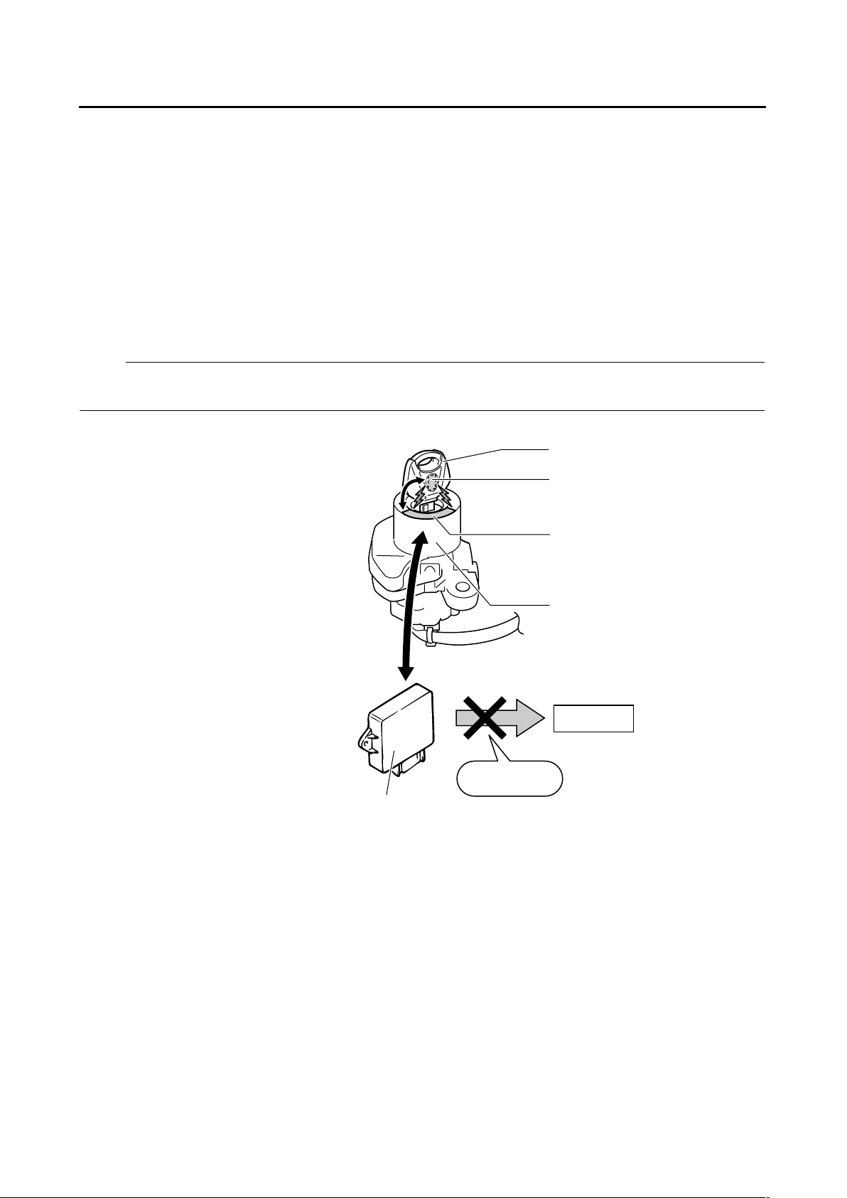
IMMOBILIZER SYSTEM
To help prevent theft, the XJR1300 is equipped with an “immobilizer system” that electronically prevents engine starting.
The key has a built-in microchip transponder that disables illegal duplicate keys by dual checking of
code between key and immobilizer unit and between immobilizer unit and ECU, thereby improving security.
After turning the main switch “ON” the ECU checks the unique key identification code and random code
through the immobilizer unit. The immobilizer unit and ECU computation results are checked with the
2 codes, and if the key is recognized as legal, the ECU releases ignition control (cutoff) and the engine
can start.
With a copy key with only identical key grooves, code verification does not proceed correctly, the ECU
fails to release ignition control and the engine cannot start.
NOTE:
While the code is being verified after the main switch is turned “ON“ the immobilizer warning light is lit.
Wait until the immobilizer warning light goes off before starting the engine.
a
a
b
c
d
e
f
g
h
a. Recognizing electronic codes
b. Sub key (black)
c. Transponder
d. Antenna
e. Immobilizer unit
f. Ignition control
g. Cut off
h. ECU
FEATURES
1-5
EAS5UXB003
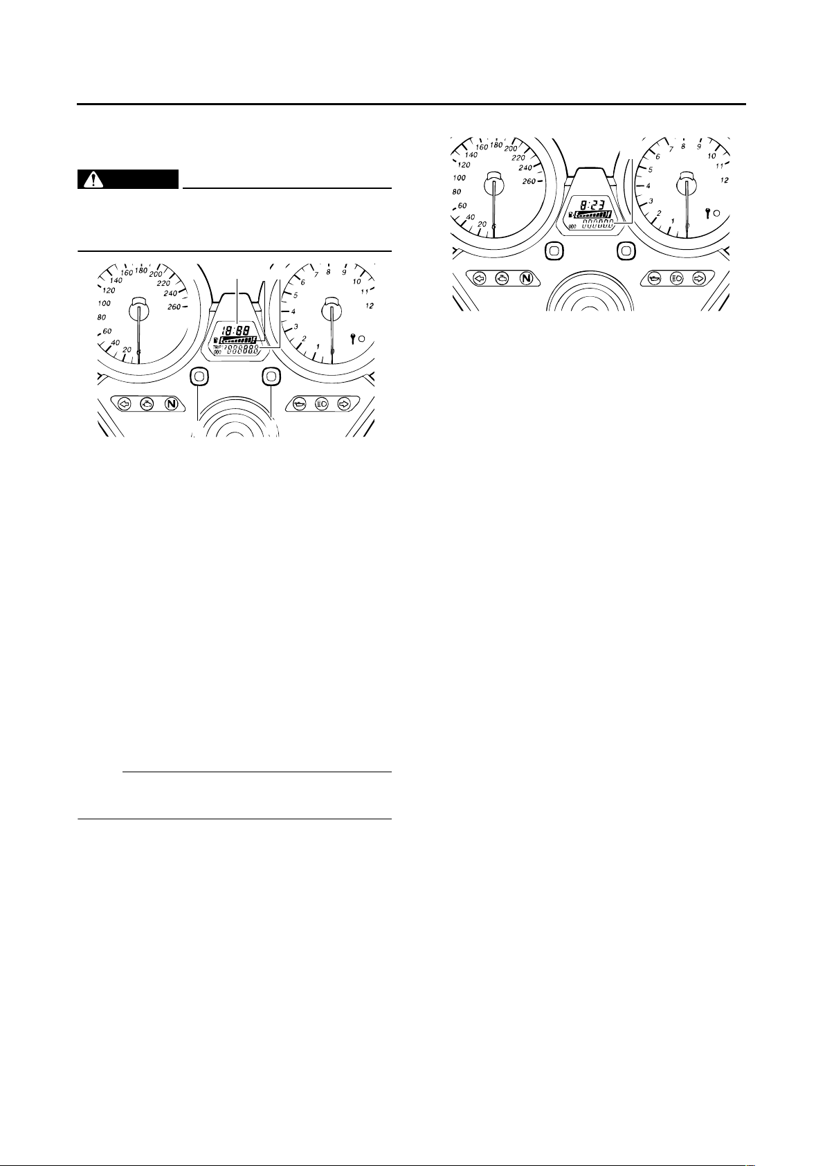
INSTRUMENT FUNCTION
Multi-function display
WARNING
EWA5UXB001
Be sure to stop the motorcycle before making any setting change to the multi-function
display.
The multi-function display is equipped with the
following:
●
an odometer (which shows the total distance
traveled)
●
two trip meters (which show the distance traveled since they were last set to zero)
●
a fuel reserve trip meter (which shows the distance traveled on the fuel reserve)
●
a fuel meter
●
a clock
●
a self-diagnosis device
NOTE:
Be sure to turn the key to “ON” before using the
“SELECT” and “RESET” buttons.
Odometer and trip meter modes
Pushing the “SELECT” button switches the display between the odometer mode “ODO” and
the trip meter modes “TRIP 1” and “TRIP 2” in
the following order:
ODO → TRIP 1 → TRIP 2 → ODO
When approximately 4.5 L (1.19 US gal) (0.99
Imp.gal) of fuel remains in the fuel tank, the display will automatically change to the fuel reserve
tripmeter mode “TRIP F” and start counting the
distance traveled from that point. In that case,
pushing the “SELECT” button switches the display between the various trip meter and odometer modes in the following order:
TRIP F → ODO → TRIP 1 → TRIP 2 → TRIP F
To reset a trip meter, select it by pushing the
“SELECT” button, and then push the “RESET”
button for at least two seconds. If you do not reset the fuel reserve tripmeter manually, it will reset itself automatically and the display will return
to the prior mode after refueling and traveling 5
km (3 mi).
1. Fuel meter
2. Clock
3. Odometer/Trip meter/Fuel reserve trip meter/
Self-diagnostic function
4. RESET button
5. SELECT button
2
3
4
5
1
1. Odometer/Trip meter/Fuel trip meter
1

FEATURES
1-6
Fuel meter
The fuel meter indicates the amount of fuel in the
fuel tank. The display segments of the fuel meter
disappear towards “E” (Empty) as the fuel level
decreases. When the fuel level warning indicator “” starts flashing, refuel as soon as possi-
ble.
NOTE:
This fuel meter is equipped with a self-diagnosis
system. If the electrical circuit is defective, the
following cycle will be repeated until the malfunction is corrected: All the display segments
and symbol “” will flash eight times, then go off
for approximately 3 seconds. If this occurs, refer
to “SIGNALING SYSTEM” on page 7-19.
Clock mode
To set the clock:
1. Turn the key to “ON”.
2. Push the “SELECT” button and “RESET” button together for at least two seconds.
3. When the hour digits start flashing, push the
“RESET” button to set the hours.
4. Push the “SELECT” button, and the minute
digits will start flashing.
5. Push the “RESET” button to set the minutes.
6. Push the “SELECT” button and then release
it to start the clock.
Self-diagnosis devices
This model is equipped with a self-diagnosis device for various electrical circuits.
If any of those circuits are defective, the engine
trouble warning light will come on, and then the
odometer/tripmeter display will indicate a
two-digit error code.
If the multi-function display indicates such an
fault code, note the code number, and check the
vehicle. Refer to “FUEL INJECTION SYSTEM”
on page 7-25.
This model is also equipped with a self-diagnosis device for the immobilizer system.
If any of the immobilizer system circuits are defective, the immobilizer system indicator light will
flash, and then the display will indicate a
two-digit error code.
NOTE:
If the display indicates error code 52, this could
be caused by transponder interference. If this
error code appears, try the following.
1. Use the code re-registering key to start the
engine.
NOTE:
Make sure there are no other immobilizer keys
close to the main switch, and do not keep more
than one immobilizer key on the same key ring!
Immobilizer system keys may cause signal interference, which may prevent the engine from
starting.
2. If the engine starts, turn it off and try starting
the engine with the standard keys.
3. If one or both of the standard keys do not
start the engine, re-register standard keys.
If the display indicates any error codes, note the
code number, and then check the vehicle. Refer
to “IMMOBILIZER SYSTEM” on page 7-69.
1. Fuel level warning indicator
2. Fuel meter
1. Clock
1
2
1
1. Error code display
1

FEATURES
1-7
CAUTION:
ECA5UXB016
If the multi-function display indicates an error code, the vehicle should be checked as
soon as possible in order to avoid engine
damage.

IMPORTANT INFORMATION
1-8
EAS20180
IMPORTANT INFORMATION
EAS20190
PREPARATION FOR REMOVAL AND
DISASSEMBLY
1. Before removal and disassembly, remove all
dirt, mud, dust and foreign material.
2. Use only the proper tools and cleaning equipment.
Refer to “SPECIAL TOOLS” on page 1-11.
3. When disassembling, always keep mated
parts together. This includes gears, cylinders, pistons and other parts that have been
“mated” through normal wear. Mated parts
must always be reused or replaced as an assembly.
4. During disassembly, clean all of the parts and
place them in trays in the order of disassembly. This will speed up assembly and allow for
the correct installation of all parts.
5. Keep all parts away from any source of fire.
EAS20200
REPLACEMENT PARTS
Use only genuine Yamaha parts for all replacements. Use oil and grease recommended by
Yamaha for all lubrication jobs. Other brands
may be similar in function and appearance, but
inferior in quality.
EAS20210
GASKETS, OIL SEALS AND O-RINGS
1. When overhauling the engine, replace all
gaskets, seals and O-rings. All gasket surfaces, oil seal lips and O-rings must be cleaned.
2. During reassembly, properly oil all mating
parts and bearings and lubricate the oil seal
lips with grease.
EAS20220
LOCK WASHERS/PLATES AND COTTER
PINS
After removal, replace all lock washers/plates
“1” and cotter pins. After the bolt or nut has been
tightened to specification, bend the lock tabs
along a flat of the bolt or nut.
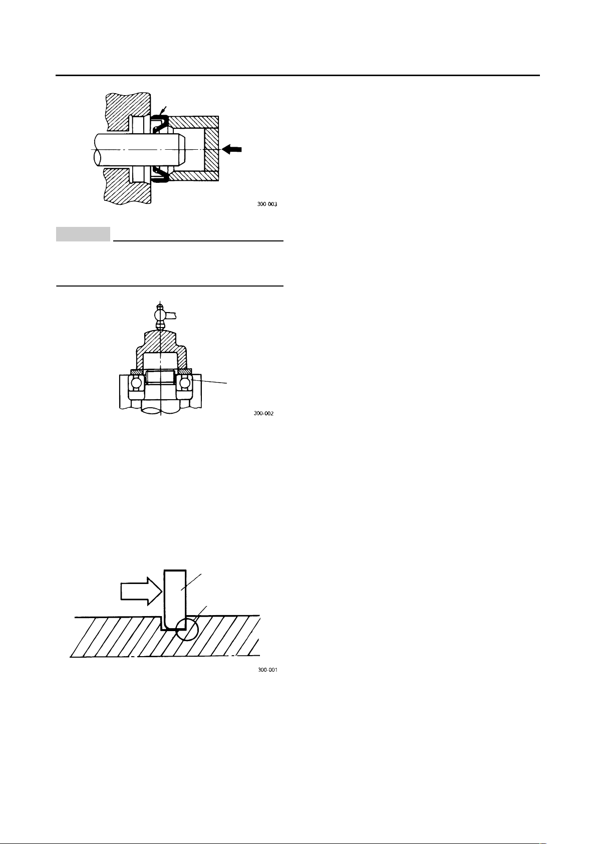
EAS20230
BEARINGS AND OIL SEALS
Install bearings and oil seals so that the manufacturer’s marks or numbers are visible. When
installing oil seals “1”, lubricate the oil seal lips
with a light coat of lithium-soap-based grease.
Oil bearings liberally when installing, if appropriate.
1
IMPORTANT INFORMATION
1-9
CAUTION:
ECA13300
Do not spin the bearing with compressed air
because this will damage the bearing surfaces.
EAS20240
CIRCLIPS
Before reassembly, check all circlips carefully
and replace damaged or distorted circlips. Always replace piston pin clips after one use.
When installing a circlip “1”, make sure the
sharp-edged corner “2” is positioned opposite
the thrust “3” that the circlip receives.
1. Bearings
a. Shaft
1
1
1
2
3
a
CHECKING THE CONNECTIONS
1-10
EAS20250
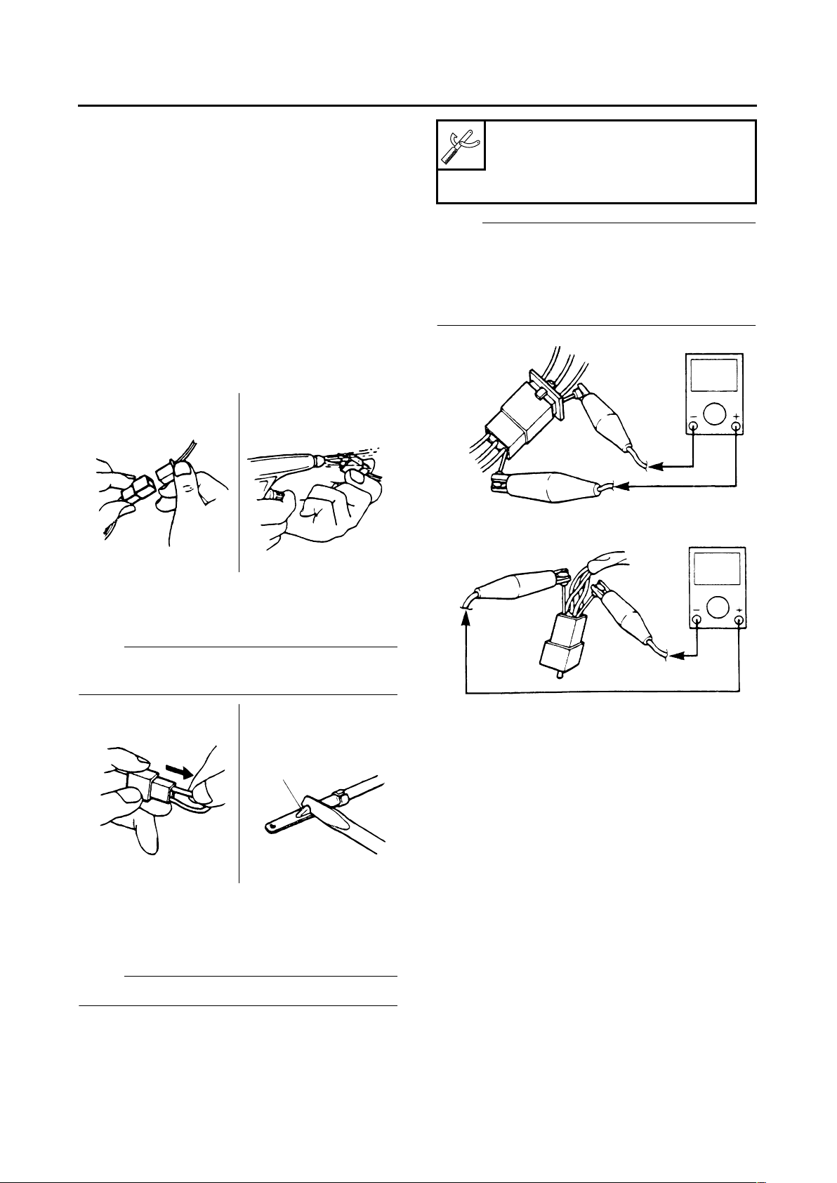
CHECKING THE CONNECTIONS
Check the leads, couplers, and connectors for
stains, rust, moisture, etc.
1. Disconnect:
● Lead
● Coupler
● Connector
2. Check:
● Lead
● Coupler
● Connector
Moisture → Dry with an air blower.
Rust/stains → Connect and disconnect several times.
3. Check:
● All connections
Loose connection → Connect properly.
NOTE:
If the pin “1” on the terminal is flattened, bend it
up.
4. Connect:
● Lead
● Coupler
● Connector
NOTE:
Make sure all connections are tight.
5. Check:
● Continuity
(with the pocket tester)
NOTE:
● If there is no continuity, clean the terminals.
● When checking the wire harness, perform
steps (1) to (3).
● As a quick remedy, use a contact revitalizer
available at most part stores.
1
Pocket tester
90890-03112
Analog pocket tester
YU-03112-C
SPECIAL TOOLS
1-11
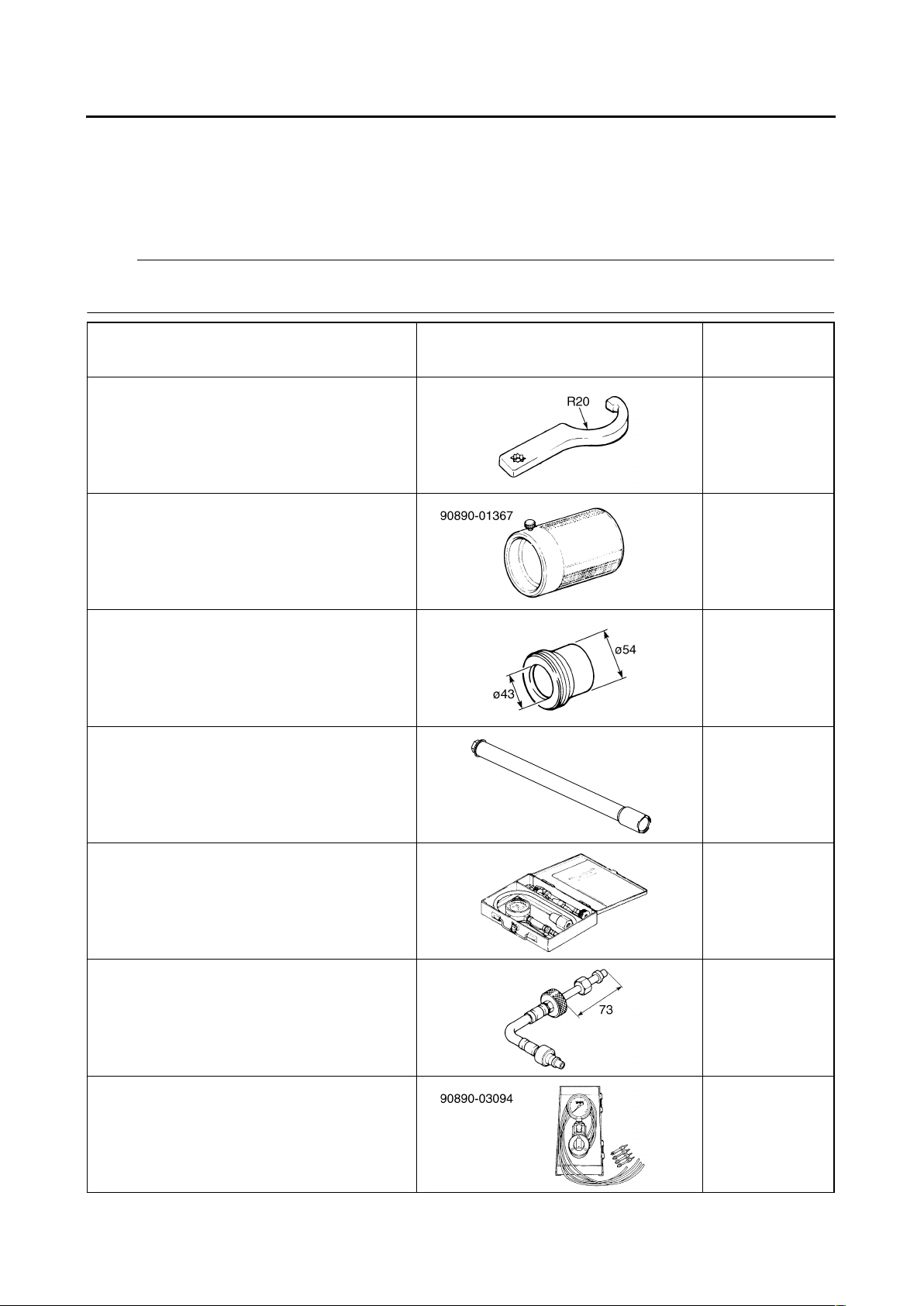
EAS20260
SPECIAL TOOLS
The following special tools are necessary for complete and accurate tune-up and assembly. Use only
the appropriate special tools as this will help prevent damage caused by the use of inappropriate tools
or improvised techniques. Special tools, part numbers or both may differ depending on the country.
When placing an order, refer to the list provided below to avoid any mistakes.
NOTE:
For U.S.A. and Canada, use part number starting with “YM-”, “YU-”, or “ACC-”.
For others, use part number starting with “90890-”.
Tool name/Tool No. Illustration
Reference
pages
Steering nut wrench
90890-01403
Spanner wrench
YU-33975
3-26, 4-52
Frok seal driver weight
90890-01367
Replacement hammer
YM-A9409-7
4-47
Fork seal driver attachment (ø43)
90890-01374
Replacement 43 mm
YM-A5142-3
4-47
Damper rod holder
90890-01513
4-45, 4-46
Compression gauge
90890-03081
Engine compression tester
YU-33223
3-12
Extension
90890-04082
3-12
Vacuum gauge
90890-03094
Carburetor synchronizer
YU-44456
3-7
SPECIAL TOOLS
1-12
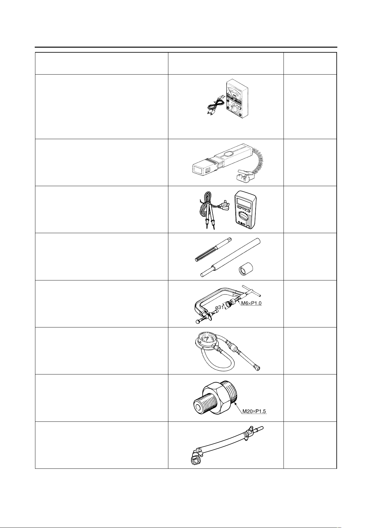
Pocket tester
90890-03112
Analog pocket tester
YU-03112-C
1-10, 5-31,
5-35, 6-8, 7-83,
7-85, 7-86,
7-90, 7-91,
7-93, 7-94,
7-95, 7-96,
7-97, 7-98,
7-99
Timing light
90890-03141
Inductive clamp timing light
YU-03141
3-11
Digital circuit tester
90890-03174
Model 88 Multimeter with tachometer
YU-A1927
6-8, 6-10
Valve guide remover & installer set (ø5.5)
90890-04016
Valve guide remover (5.5 mm)
YM-01122
5-19
Valve spring compressor
90890-04019
YM-04019
5-17, 5-23
Pressure gauge
90890-03153
3-15, 6-7
Oil pressure adapter B
90890-03124
3-15
Fuel pressure adapter
90890-03176
YM-03176
6-7
Tool name/Tool No. Illustration
Reference
pages
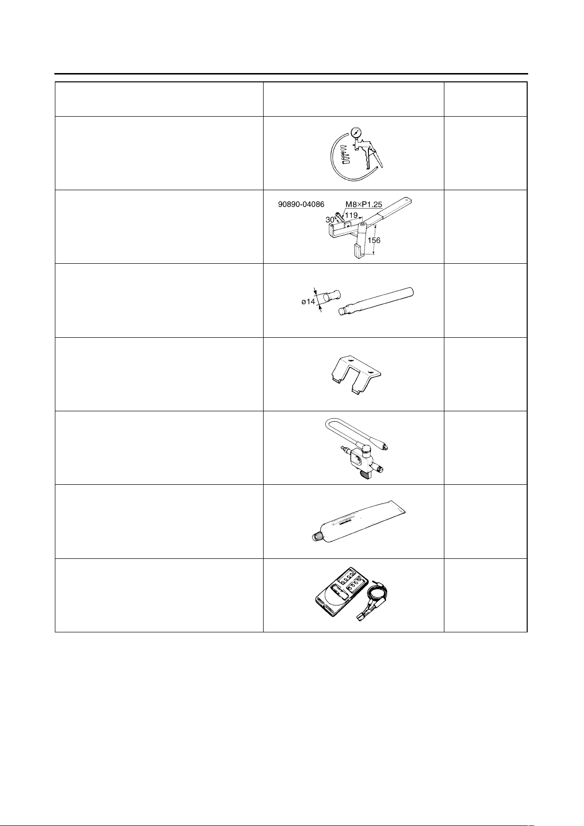
SPECIAL TOOLS
1-13
Vacuum/pressure pump gauge set
90890-06756
Mityvac brake bleeding tool
YS-42423
6-7
Universal clutch holder
90890-04086
YM-91042
5-44, 5-47
Valve lapper
90890-04101
Valve lapping tool
YM-A8998
5-20
Tappet adjusting tool
90890-04110
Valve adjustment tool
YM-33966
3-5
Ignition checker
90890-06754
Opama pet-4000 spark checker
YM-34487
7-92
Yamaha bond No. 1215 (Three Bond
No.1215®)
90890-85505
5-63
Digital tachometer
90890-06760
YU-39951-B
3-7, 3-9, 3-11
Tool name/Tool No. Illustration
Reference
pages

SPECIFICATIONS
GENERAL SPECIFICATIONS ...................................................................... 2-1
ENGINE SPECIFICATIONS .......................................................................... 2-2
CHASSIS SPECIFICATIONS ........................................................................ 2-9
ELECTRICAL SPECIFICATIONS ................................................................. 2-12
TIGHTENING TORQUE................................................................................. 2-15
GENERAL TIGHTENING TORQUE SPECIFICATIONS......................... 2-15
ENGINE................................................................................................... 2-15
CHASSIS................................................................................................. 2-18
LUBRICATION POINTS AND LUBRICANT TYPES .................................... 2-21
ENGINE................................................................................................... 2-21
CHASSIS................................................................................................. 2-22
LUBRICATION DIAGRAMS.......................................................................... 2-25
CABLE ROUTING ......................................................................................... 2-31
1
2
3
4
5
6
7
8
9

GENERAL SPECIFICATIONS
2-1
EAS20280
GENERAL SPECIFICATIONS
Model
Model 5WMG (EUR)
5WMJ (OCE)
Dimensions
Overall length 2175 mm (85.6 in)
Overall width 765 mm (30.1 in)
Overall height 1115 mm (43.9 in)
Seat height 795 mm (31.3 in)
Wheelbase 1500 mm (59.1 in)
Ground clearance 125 mm (4.92 in)
Minimum turning radius 2800 mm (110.2 in)
Weight
With oil and fuel 245.0 kg (540 lb)
Maximum load 205 kg (452 lb)

ENGINE SPECIFICATIONS
2-2
EAS20290
ENGINE SPECIFICATIONS
Engine
Engine type Air cooled 4-stroke, DOHC
Displacement 1251.0 cm
3
Cylinder arrangement Forward-inclined parallel 4-cylinder
Bore × stroke 79.0 × 63.8 mm (3.11 × 2.51 in)
Compression ratio 9.70 :1
Standard compression pressure (at sea level) 1050 kPa/400 r/min (149.3 psi/400 r/min) (10.5
kgf/cm
2
/400 r/min)
Minimum–maximum 900–1200 kPa (128.0–170.7 psi) (9.0–12.0 kgf/
cm
2
)
Starting system Electric starter
Fuel
Recommended fuel Premium unleaded gasoline only
Fuel tank capacity 21.0 L (5.55 US gal) (4.62 Imp.gal)
Fuel reserve amount 4.5 L (1.19 US gal) (0.99 Imp.gal)
Engine oil
Lubrication system Wet sump
Type SAE10W30, SAE10W40, SAE15W40,
SAE20W40 or SAE20W50
Recommended engine oil grade API service SG type or higher, JASO standard
MA
Engine oil quantity
Total amount 4.20 L (4.44 US qt) (3.70 Imp.qt)
Without oil filter element replacement 2.80 L (2.96 US qt) (2.46 Imp.qt)
With oil filter element replacement 3.15 L (3.33 US qt) (2.77 Imp.qt)
Oil cooler capacity (including all routes) 0.2 L (0.21 US qt) (0.18 Imp.qt)
Oil pressure (hot) 80.0 kPa/1000 r/min (11.6 psi/1000 r/min) (0.80
kgf/cm
2
/1000 r/min)
Oil filter type Paper
Oil pump
Oil pump type Trochoid
Inner-rotor-to-outer-rotor-tip clearance 0.120 mm or less (0.0047 in or less)
Limit 0.20 mm (0.0079 in)
Outer-rotor-to-oil-pump-housing clearance 0.090–0.150 mm (0.0035–0.0059 in)
Limit 0.160 mm (0.0063 in)
Oil-pump-housing-to-inner-and-outer-rotor clearance
0.03–0.08 mm (0.0012–0.0032 in)
Limit 0.15 mm (0.0059 in)
Bypass valve opening pressure 180.0–220.0 kPa (26.1–31.9 psi) (1.80–2.20
kgf/cm
2
)
Relief valve operating pressure 480.0–580.0 kPa (69.6–84.1 psi) (4.80–5.80
kgf/cm
2
)
Pressure check location MAIN GALLERY
Spark plug (s)
Manufacturer/model NGK/DPR8EA-9
Spark plug gap 0.8–0.9 mm (0.031–0.035 in)
Cylinder head

ENGINE SPECIFICATIONS
2-3
Volume 33.90–34.70 cm3 (2.07–2.12 cu.in)
Warpage limit 0.20 mm (0.0079 in)
Camshaft
Drive system Chain drive (center)
Camshaft cap inside diameter 25.000–25.021 mm (0.9843–0.9851 in)
Camshaft journal diameter 24.967–24.980 mm (0.9830–0.9835 in)
Camshaft-journal-to-camshaft-cap clearance 0.020–0.054 mm (0.0008–0.0021 in)
Camshaft lobe dimensions
Intake A 35.849–35.949 mm (1.4114–1.4153 in)
Limit 35.749 mm (1.4074 in)
Intake B 28.010–28.110 mm (1.1023–1.1067 in)
Limit 27.910 mm (1.0988 in)
Exhaust A 35.950–36.050 mm (1.4154–1.4193 in)
Limit 35.850 mm (1.4114 in)
Exhaust B 28.045–28.145 mm (1.1041–1.1081 in)
Limit 27.945 mm (1.1002 in)
Camshaft runout limit 0.030 mm (0.0012 in)
Timing chain
Model/number of links 79RH2015/156
Tensioning system Automatic
Valve, valve seat, valve guide
Valve clearance (cold)
Intake 0.11–0.15 mm (0.0043–0.0059 in)
Exhaust 0.16–0.20 mm (0.0063–0.0079 in)
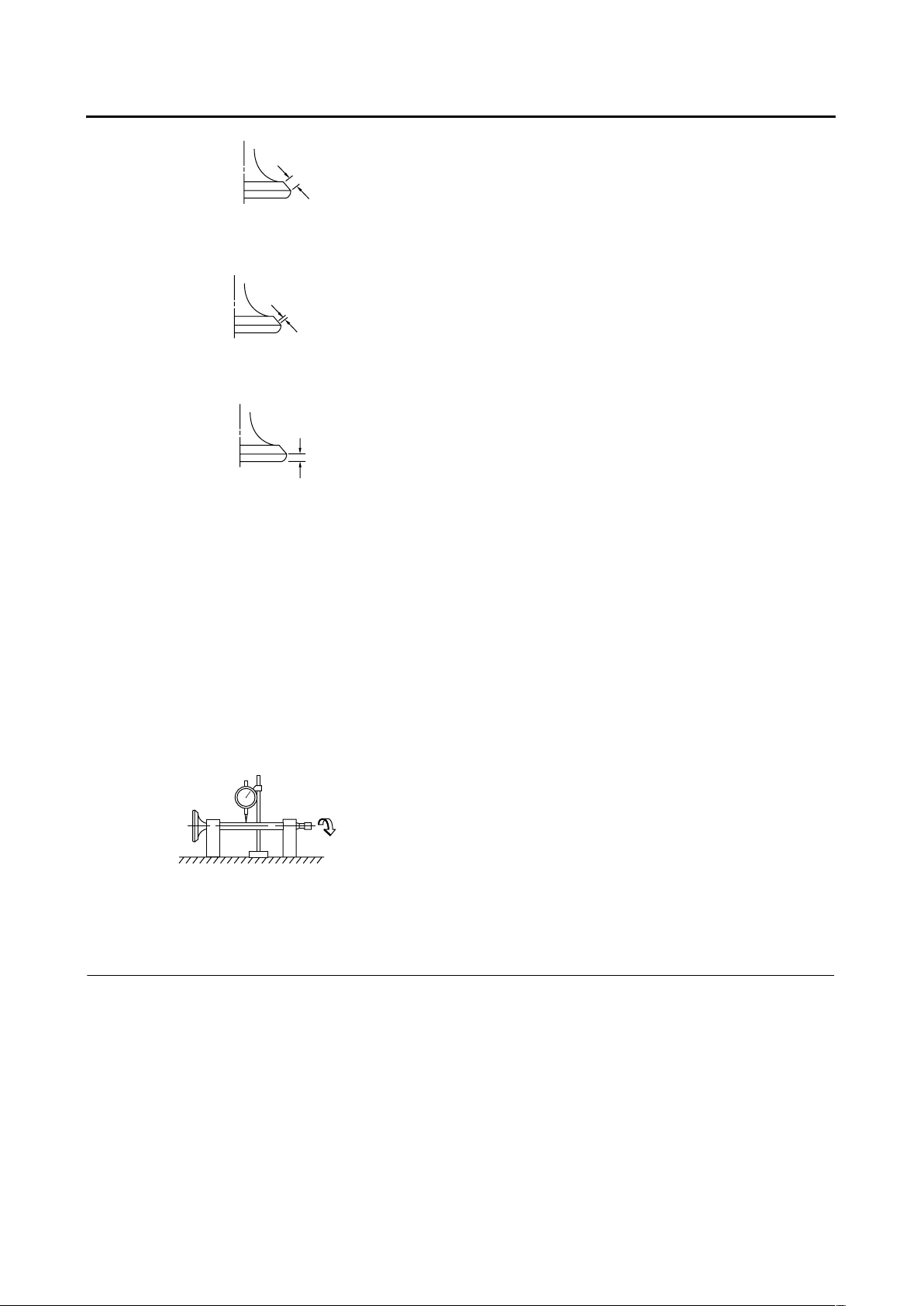
Valve dimensions
Valve head diameter A (intake) 28.90–29.10 mm (1.1378–1.1457 in)
Valve head diameter A (exhaust) 24.90–25.10 mm (0.9803–0.9882 in)
Valve face width B (intake) 1.980–2.550 mm (0.0780–0.1004 in)
Valve face width B (exhaust) 1.980–2.550 mm (0.0780–0.1004 in)
A
B
A
ENGINE SPECIFICATIONS
2-4
Valve seat width C (intake) 0.90–1.10 mm (0.0354–0.0433 in)
Valve seat width C (exhaust) 0.90–1.10 mm (0.0354–0.0433 in)
Valve margin thickness D (intake) 0.80–1.20 mm (0.0315–0.0472 in)
Valve margin thickness D (exhaust) 0.80–1.20 mm (0.0315–0.0472 in)
Valve stem diameter (intake) 5.475–5.490 mm (0.2156–0.2161 in)
Limit 5.445 mm (0.2144 in)
Valve stem diameter (exhaust) 5.460–5.475 mm (0.2150–0.2156 in)
Limit 5.430 mm (0.2138 in)
Valve guide inside diameter (intake) 5.500–5.512 mm (0.2165–0.2170 in)
Limit 5.552 mm (0.2186 in)
Valve guide inside diameter (exhaust) 5.500–5.512 mm (0.2165–0.2170 in)
Limit 5.552 mm (0.2186 in)
Valve-stem-to-valve-guide clearance (intake) 0.010–0.037 mm (0.0004–0.0015 in)
Limit 0.080 mm (0.0032 in)
Valve-stem-to-valve-guide clearance (exhaust) 0.025–0.052 mm (0.0010–0.0020 in)
Limit 0.100 mm (0.0039 in)
Valve stem runout 0.010 mm (0.0004 in)
Cylinder head valve seat width (intake) 0.90–1.10 mm (0.0354–0.0433 in)
Limit 1.6 mm (0.06 in)
Cylinder head valve seat width (exhaust) 0.90–1.10 mm (0.0354–0.0433 in)
Limit 1.6 mm (0.06 in)
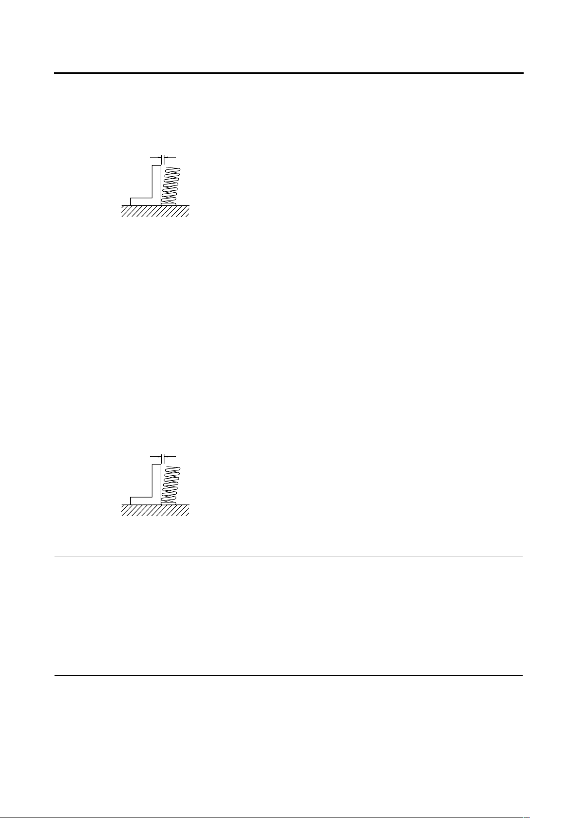
Valve spring
Inner spring
Free length (intake) 39.65 mm (1.56 in)
Free length (exhaust) 39.65 mm (1.56 in)
Installed length (intake) 32.80 mm (1.29 in)
Installed length (exhaust) 32.80 mm (1.29 in)
Spring rate K1 (intake) 9.80 N/mm (55.96 lb/in) (1.00 kgf/mm)
Spring rate K2 (intake) 12.40 N/mm (70.80 lb/in) (1.26 kgf/mm)
Spring rate K1 (exhaust) 9.80 N/mm (55.96 lb/in) (1.00 kgf/mm)
Spring rate K2 (exhaust) 12.40 N/mm (70.80 lb/in) (1.26 kgf/mm)
Installed compression spring force (intake) 61.70–72.50 N (13.87–16.30 lbf) (6.29–7.39
B
C
D
ENGINE SPECIFICATIONS
2-5
kgf)
Installed compression spring force (exhaust) 61.70–72.50 N (13.87–16.30 lbf) (6.29–7.39
kgf)
Spring tilt (intake) 2.5 °/1.7 mm (2.5 °/0.067 in)
Spring tilt (exhaust) 2.5 °/1.7 mm (2.5 °/0.067 in)
Winding direction (intake) Clockwise
Winding direction (exhaust) Clockwise
Outer spring
Free length (intake) 41.10 mm (1.62 in)
Free length (exhaust) 41.10 mm (1.62 in)
Installed length (intake) 34.80 mm (1.37 in)
Installed length (exhaust) 34.80 mm (1.37 in)
Spring rate K1 (intake) 22.60 N/mm (129.05 lb/in) (2.30 kgf/mm)
Spring rate K2 (intake) 28.80 N/mm (164.45 lb/in) (2.94 kgf/mm)
Spring rate K1 (exhaust) 22.60 N/mm (129.05 lb/in) (2.30 kgf/mm)
Spring rate K2 (exhaust) 28.80 N/mm (164.45 lb/in) (2.94 kgf/mm)
Installed compression spring force (intake) 130.40–154.00 N (29.31–34.62 lbf)
(13.30–15.70 kgf)
Installed compression spring force (exhaust) 130.40–154.00 N (29.31–34.62 lbf)
(13.30–15.70 kgf)
Spring tilt (intake) 2.5 °/1.8 mm (2.5 °/0.071 in)
Spring tilt (exhaust) 2.5 °/1.8 mm (2.5 °/0.071 in)
Winding direction (intake) Counter clockwise
Winding direction (exhaust) Counter clockwise
Valve lifter
Valve lifter outside diameter (intake) 27.978–28.002 mm (1.1015–1.1024 in)
Limit 27.958 mm (1.1007 in)
Valve lifter outside diameter (exhaust) 27.978–28.002 mm (1.1015–1.1024 in)
Limit 27.958 mm (1.1007 in)
Valve lifter hole inside diameter (intake) 27.996–28.020 mm (1.1022–1.1031 in)
Limit 28.050 mm (1.1043 in)
Valve lifter hole inside diameter (exhaust) 27.996–28.020 mm (1.1022–1.1031 in)
Limit 28.050 mm (1.1043 in)
Cylinder
Bore 79.000–79.010 mm (3.1102–3.1106 in)
Wear limit 79.100 mm (3.1142 in)
Taper limit 0.050 mm (0.0020 in)
Out of round limit 0.100 mm (0.0039 in)
Warp limit 0.03 mm (0.0012 in)

ENGINE SPECIFICATIONS
2-6
Piston
Piston-to-cylinder clearance 0.015–0.040 mm (0.0006–0.0016 in)
Limit 0.15 mm (0.0059 in)
Diameter D 78.970–78.985 mm (3.1090–3.1096 in)
Height H 5.0 mm (0.20 in)
Offset 1.00 mm (0.0394 in)
Offset direction Intake side
Piston pin bore inside diameter 18.004–18.015 mm (0.7088–0.7093 in)
Limit 18.045 mm (0.7104 in)
Piston pin outside diameter 17.991–18.000 mm (0.7083–0.7087 in)
Limit 17.971 mm (0.7075 in)
Piston ring
Top ring
Ring type Barrel
Dimensions (B × T) 1.00 × 3.05 mm (0.04 × 0.12 in)
End gap (installed) 0.20–0.35 mm (0.0079–0.0138 in)
Limit 0.60 mm (0.0236 in)
Ring side clearance 0.045–0.080 mm (0.0018–0.0032 in)
Limit 0.100 mm (0.0039 in)
2nd ring
Ring type Taper
H
D
T
B
B
T
ENGINE SPECIFICATIONS
2-7
Dimensions (B × T) 1.20 × 3.00 mm (0.05 × 0.12 in)
End gap (installed) 0.35–0.50 mm (0.0138–0.0197 in)
Limit 0.75 mm (0.0295 in)
Ring side clearance 0.030–0.070 mm (0.0012–0.0028 in)
Limit 0.100 mm (0.0039 in)
Oil ring
Dimensions (B × T) 2.50 × 2.90 mm (0.10 × 0.11 in)
End gap (installed) 0.20–0.50 mm (0.0079–0.0197 in)
Ring side clearance 0.050–0.155 mm (0.0020–0.0061 in)
Connecting rod
Oil clearance (using plastigauge®) 0.021–0.045 mm (0.0008–0.0018 in)
Limit 0.08 mm (0.0032 in)
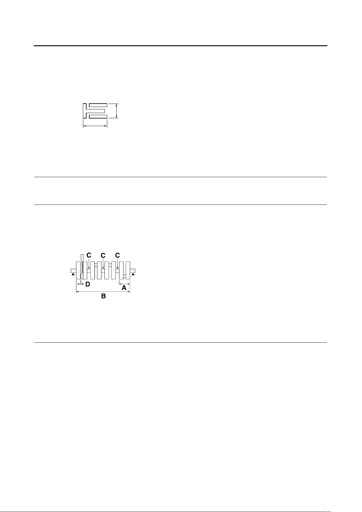
Crankshaft
Width A 62.25–63.85 mm (2.451–2.514 in)
Width B 382.00–383.20 mm (15.04–15.09 in)
Runout limit C 0.020 mm (0.0008 in)
Big end side clearance D 0.160–0.262 mm (0.0063–0.0103 in)
Limit 0.50 mm (0.0197 in)
Big end radial clearance E 0.023–0.047 mm (0.0009–0.0019 in)
Journal oil clearance (using plastigauge®) 0.020–0.044 mm (0.0008–0.0017 in)
Limit 0.09 mm (0.0035 in)
Clutch
Clutch type Wet, multiple-disc
Clutch release method Hydraulic inner push
Friction plate thickness 2.90–3.10 mm (0.114–0.122 in)
Wear limit 2.80 mm (0.1102 in)
Plate quantity 8 pcs
Clutch plate thickness 1.90–2.10 mm (0.075–0.083 in)
Plate quantity 7 pcs
Warpage limit 0.15 mm (0.059 in)
Clutch spring height 6.78 mm (0.27 in)
Spring quantity 1 pcs
Push rod bending limit 0.300 mm (0.0118 in)
B
T
 Loading...