

Yamaha VMX17YB (2009) Assembly Manual

2009
MOTORCYCLE / MOTOCYCLETTE
ASSEMBLY MANUAL / MANUEL
D'ASSEMBLAGE
Model : VMX17YB
2S3281077000
*2S3281077000*
FOREWORD
This Assembly Manual contains the information required for the correct assembly of
this Yamaha vehicle prior to delivery to the
customer. Since some external parts of the
vehicle have been removed at the Yamaha
factory for the convenience of packing, assembly by the Yamaha dealer is required.
It should be noted that the assembled vehicle should be thoroughly cleaned, inspected, and adjusted prior to delivery to the
customer.
IMPORTANT
The service specifications given in this assembly manual are based on the model as
manufactured. Yamaha Motor Company,
Ltd. is continually striving to improve all of
its models. Modifications and significant
changes in specifications or procedures
will be forwarded to all authorized Yamaha
dealers and will appear in future editions of
this manual where applicable. The procedures below are described in the order that
the procedures are carried out correctly
and completely. Failure to do so can result
in poor performance and possible harm to
the vehicle and/or rider.
IMPORTANT MANUAL IN-
FORMATION
Particularly important information is distinguished in this manual by the following notations.
This is the safety alert symbol. It is
used to alert you to potential personal
injury hazards. Obey all safety messages that follow this symbol to avoid
possible injury or death.
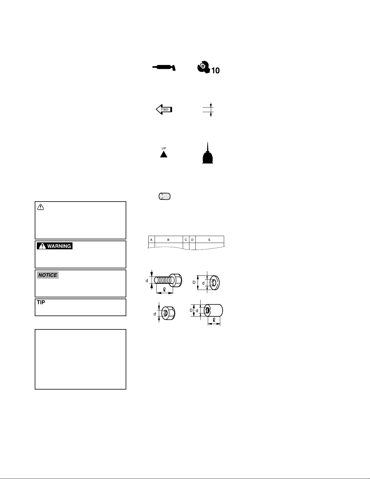
SYMBOLS USED IN THE
ASSEMBLY MANUAL
(1) (2)
(3) (4)
(5) (6)
(7)
(8)
In order to simplify descriptions in this assembly manual, the following symbols are
used:
(1): Coat with lithium-soap-based grease.
(2): Tighten to 10 Nm. (10 Nm = 1.0 m•kg
= 7.2 ft•lb)
(3): Towards the front of the vehicle
(4): Clearance required
(5): Install so that the arrow mark faces
upward.
(6): Apply motor oil.
(7): Made of rubber or plastics
(8):
A: Ref. No. (indicating the order of
operations.)
B: Part name
C: Quantity of parts per vehicle
D: Place where parts are held
V: Stored in plastic bag
C: Stored in carton box
S: Fixed inside the steel frame
and/or contained in the Styrofoam tray (upper or lower)
*: Temporarily installed or se-
cured
E: Size or material of parts
d/D: Diameter of part
L: Length of part
e.g., 5 (0.20) = 5 mm (0.20 in)
A WARNING indicates a hazardous
situation which, if not avoided, could
result in death or serious injury.
A NOTICE indicates special precautions that must be taken to avoid damage to the vehicle or other property.
A TIP provides key information to make
procedures easier or clearer.
VMX17Y
ASSEMBLY MANUAL
©2008 by Yamaha Motor Co., Ltd.
First Edition, September 2008
All rights reserved.
Any reproduction or unauthorized use
without the written permission of
Yamaha Motor Co., Ltd.
is expressly prohibited.
PREPARATION
To assemble the vehicle correctly, supplies
(e.g., oils, greases, and shop rags) and
sufficient working space are required.
Workshop
The workshop where the vehicle is assembled should be clean, spacious, and have a
level floor.
Self-protection
Protect your eyes with suitable safety
glasses or goggles when using compressed air, when grinding or when doing
any operation which may cause particles to
fly off. Protect hands and feet by wearing
safety gloves or shoes.
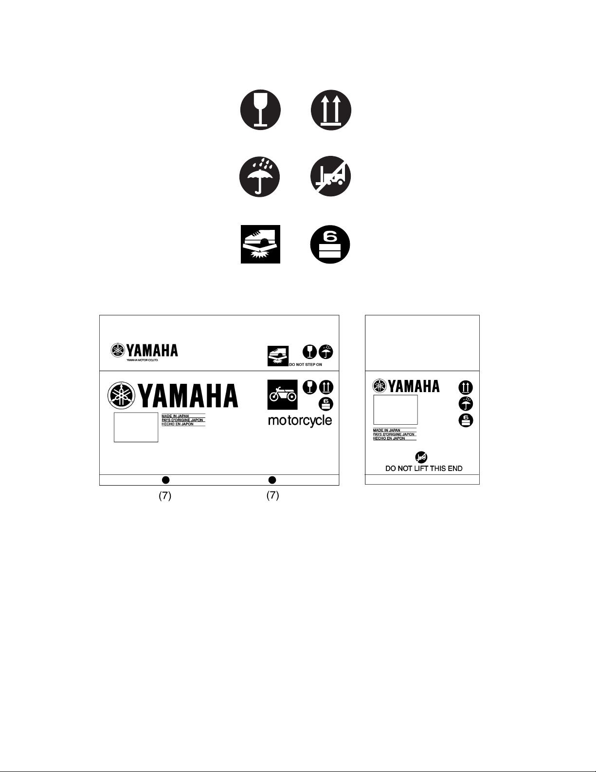
SYMBOLS USED ON
CRATE CARTON
(1) (2)
(3)
(5)
(4)
(6)
(1) Contents of the transport package are
fragile, therefore the package must be
handled with care.
(2) Indicates correct upright position of the
transport package.
(3) Transport package must be kept away
from rain.
(4) Insertion of the forklift arms from this
side can cause damage.
(5) Do not step anywhere on this carton
box.
(6) Up to 6 of the transport packages can
be piled up.
(7) Lift arm insertion position
If the forklift arms cannot be inserted
under the transport package in alignment with the two yellow labels, adjust
the arms so that they are positioned
evenly in relation to these marks while
taking care not to damage the package
contents.
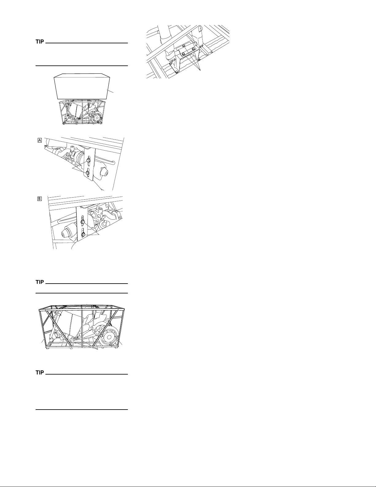
UNPACKING
1. Remove the frame cover (1).
To remove the frame cover, cut the plastic
bands around the cover using a cutter or
scissors.
1
2. Remove the handlebar holder bolts (2).
2
4
2
A. Right
B. Left
3. Remove the packing frames (3). (Lift
up and then move to the side.)
Remove the bolts while holding the frame.
3
3
3
4. Remove the front wheel axle holder
bolts (4).
Before starting the assembly, check for
damaged or missing parts. Check both the
parts contained in the carton boxes and on
the vehicle for damage, scratches, and other defects.
3
-1-
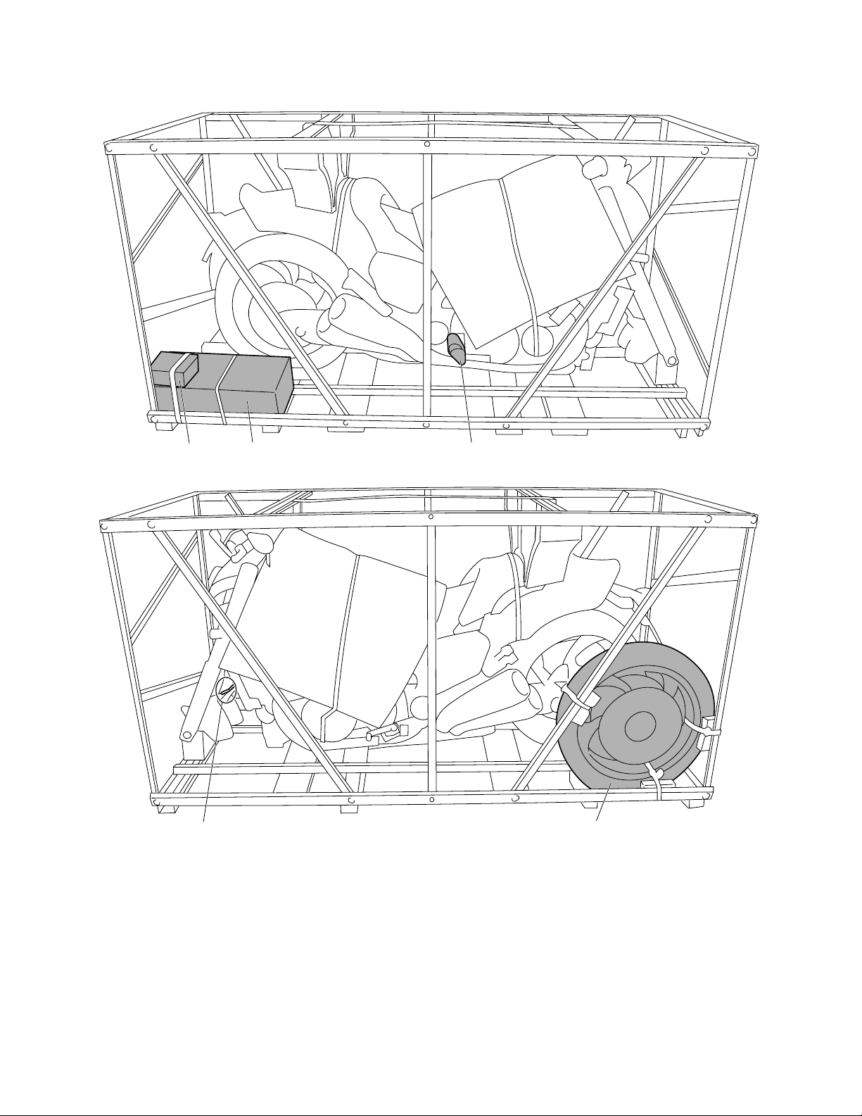
PARTS LOCATION
312
1. Carton box 1
2. Carton box 2
3. Bubble wrap pack
4. Plastic bag
5. Front wheel
54
-2-
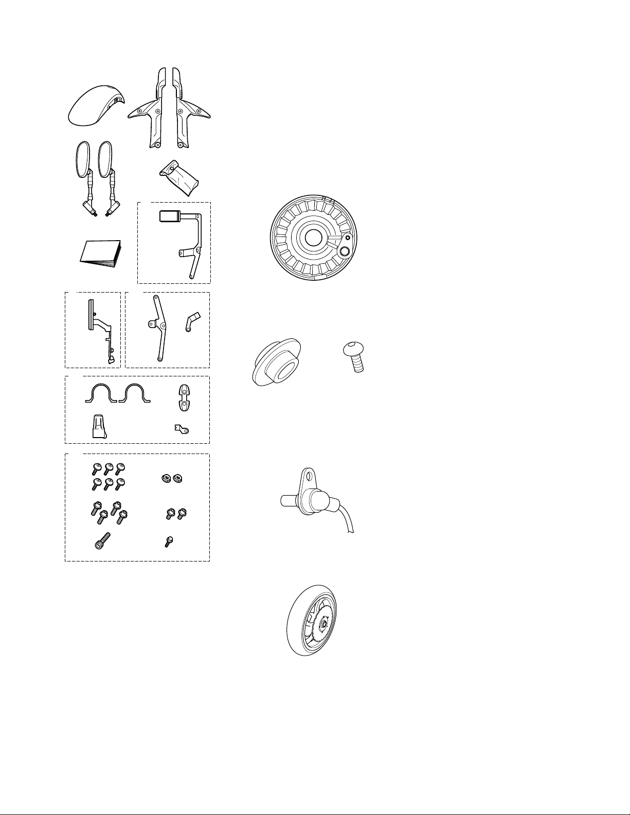
Carton box 1
1
3
19. Hexagon socket bolts (front fork guard)
[d = 6 (0.24), L = 16 (0.63)]
20. Flange nuts (front fork guard) [d = 6
2
4
(0.24)]
21. Hexagon socket bolts (front fender
stay) [d = 6 (0.24), L = 16 (0.63)]
22. Hexagon socket bolts (front brake
hose clamp) [d = 6 (0.24), L = 10
(0.39)]
23. Hexagon socket bolt (front brake hose
holder) [d = 6 (0.24), L = 10 (0.39)]
24. Flange bolt (front wheel sensor lead
holder) [d = 6 (0.24), L = 12 (0.47)]
Carton box 2
6
7
5
8
9
10
11 12
13
14 15
16 17
18
19 20
1
1. Front wheel sensor housing
Bubble wrap pack
1
1. Collar (front wheel) [d = 22 (0.87)]
2. Hexagon socket bolt (front wheel sensor) [d = 6 (0.24), L = 14 (0.55)]
Plastic bag
1
2
21 22
23 24
1. Front fender
2. Front fork guards
3. Rear view mirrors
4. Owner's tool kit 2
5. Owner's manual
6. Plastic bag
7. Right front fender bracket
8. Plastic bag
9. Front brake hose bracket
10. Plastic bag
11. Left front fender bracket
12. Front brake hose holder
13. Plastic bag
14. Front fender stays
15. Front brake hose clamp
16. Key holder
17. Front wheel sensor lead holder
18. Plastic bag
1. Front wheel sensor
Front wheel
1
1. Front wheel
-3-
SETUP AND PREDELIVERY CHECKLIST
VMX17Y
Check the following items again after setup and predelivery service have been completed.
A: INSTALLATION OF THE PARTS INCLUDED IN THE CRATE
□ FRONT WHEEL □ REAR VIEW MIRRORS
□ FRONT FENDER □ BATTERY
B: TIGHTENING TORQUE OF EACH PART
□ Front wheel axle bolt 81 Nm (8.1 m•kg, 59 ft•lb)
□ Front wheel axle pinch bolt 21 Nm (2.1 m•kg, 15 ft•lb)
□ Front brake caliper bolt 35 Nm (3.5 m•kg, 25 ft•lb)
□ Bolt (front wheel sensor lead holder) 7 Nm (0.7 m•kg, 5.1 ft•lb)
□ Front wheel sensor bolt 7 Nm (0.7 m•kg, 5.1 ft•lb)
□ Bolt (front fender stay) 10 Nm (1.0 m•kg, 7.2 ft•lb)
□ Bolt (front fork guard) 10 Nm (1.0 m•kg, 7.2 ft•lb)
□ Bolt (front brake hose holder) 10 Nm (1.0 m•kg, 7.2 ft•lb)
□ Bolt (front brake hose clamp) 10 Nm (1.0 m•kg, 7.2 ft•lb)
□ Bolt (battery cover) 3 Nm (0.3 m•kg, 2.2 ft•lb)
□ Bolt (top cover) 1.5 Nm (0.15 m•kg, 1.1 ft•lb)
□ Bolt (top cover) 7 Nm (0.7 m•kg, 5.1 ft•lb)
□ Bolt (multi-function display cover) 7 Nm (0.7 m•kg, 5.1 ft•lb)
□ Bolt (rider seat) 7 Nm (0.7 m•kg, 5.1 ft•lb)
C: ROUTING OF WIRE, CABLES, ETC.
□ Front wheel sensor lead □ Front brake hose
□ Positive battery lead □ Negative battery lead
D: ADJUSTMENTS
□ CHECKING AND CHARGING THE BATTERY □ BLEEDING THE HYDRAULIC BRAKE SYSTEM
□ MEASURING THE TIRE PRESSURE □ ADJUSTING THE CLUTCH LEVER
□ CHECKING THE ENGINE OIL LEVEL □ CHECKING THE CLUTCH FLUID LEVEL
□ CHECKING THE FINAL GEAR OIL LEVEL □ BLEEDING THE HYDRAULIC CLUTCH SYSTEM
□ CHECKING THE COOLANT LEVEL □ ADJUSTING THE FRONT FORK LEGS
□ ADJUSTING THE THROTTLE CABLE FREE PLAY □ ADJUSTING THE REAR SHOCK ABSORBER ASSEMBLY
□ ADJUSTING THE FRONT BRAKE □ ADJUSTING THE HEADLIGHT BEAM
□ ADJUSTING THE REAR BRAKE LIGHT SWITCH □ ADJUSTING THE DIGITAL CLOCK
□ CHECKING THE BRAKE FLUID LEVEL
E: FUNCTION AND PERFORMANCE
□ Check the function of the headlight, meter light and taillight □ Check the function of the indicator on the speedometer
□ Check the function of the brake light □ Check the feel of the brakes
□ Check the function of the turn signal lights and indicator lights □ Check engine for irregular noise (Yes/No)
□ Check the tone quality of the horn □ Check for exhaust leak (Yes/No)
F: ACCESSORIES, ETC. FOR DELIVERY
Owner's manual □ Key holder
□
□ Owner's tool kit
-4-
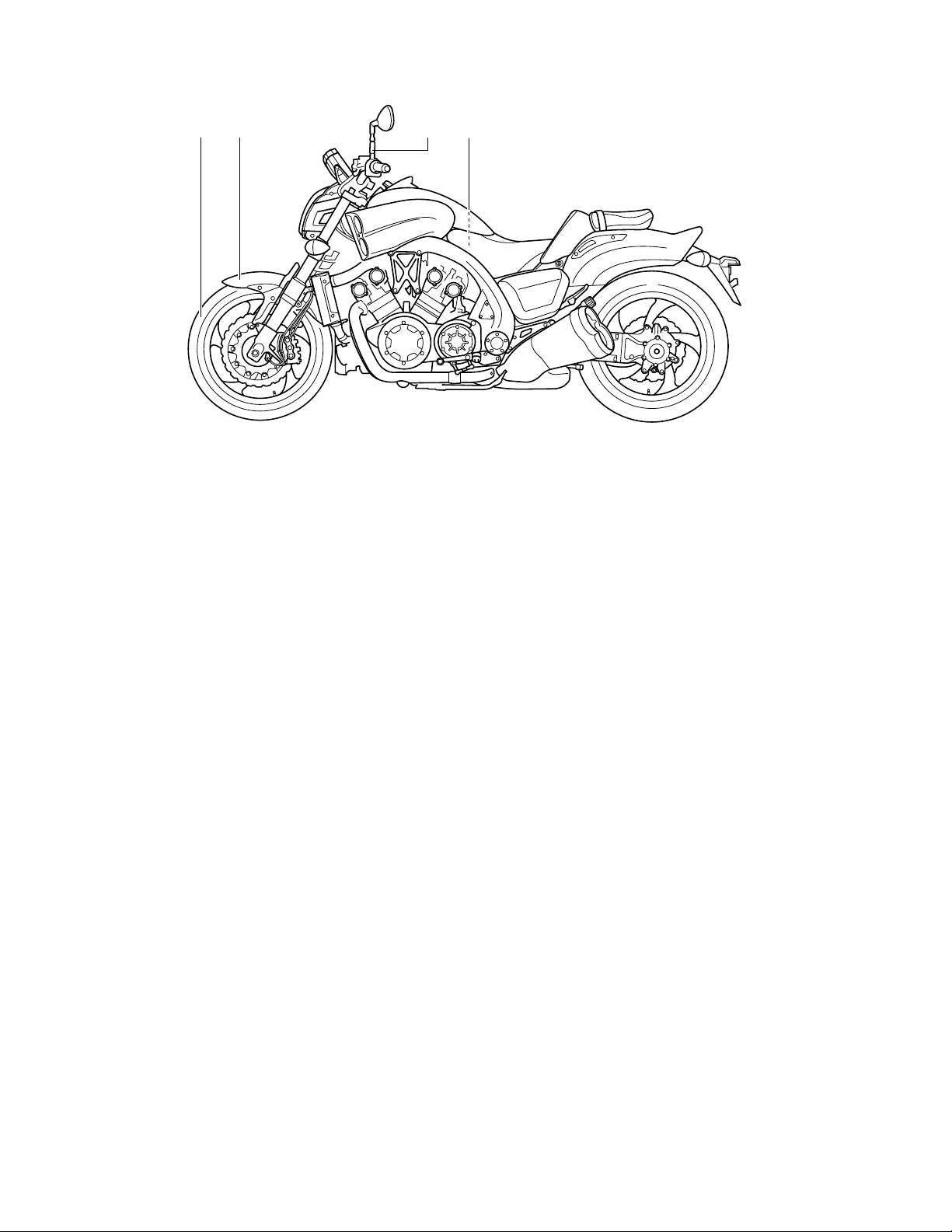
SETUP PROCEDURES
Perform the setup procedures in the order indicated by the numbers. Always follow the order as shown.
12 43
-5-
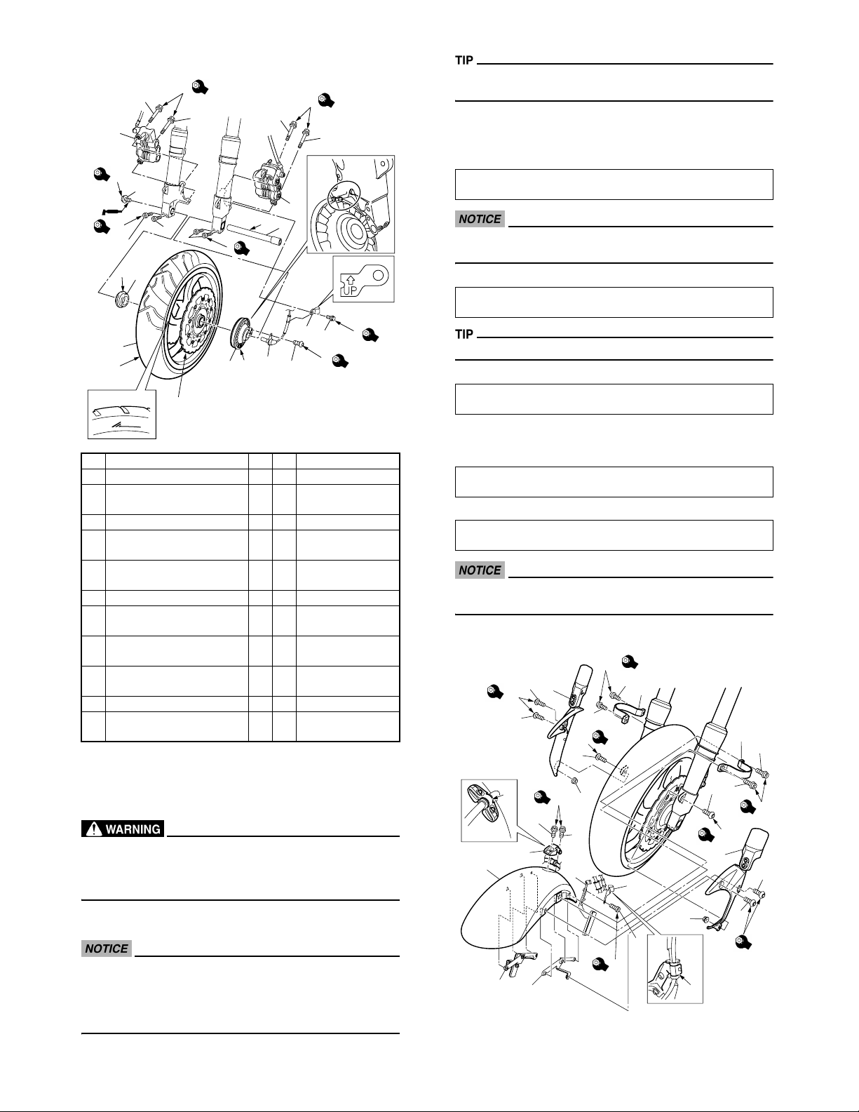
1. FRONT WHEEL
J
8
7
35
J
8
8
35
8
G
H
81
5
7
B
21
11
D
1C
1V
4
K
9
10
M
12
d = 14 (0.55), L =
23 (0.91)
d = 8 (0.31), L = 45
(1.77)
d = 10 (0.39), L =
71 (2.8)
d = 6 (0.24), L = 12
(0.47)
d = 6 (0.24), L = 14
(0.55)
L
7
7
I
21
6
C
6
6
I
2
1
F
F
1 Front wheel 1 S
2 Collar 1 V d = 22 (0.87)
Front wheel sensor hous-
3
ing
4 Front wheel axle 1 *
5 Front wheel axle bolt 1 *
6 Front wheel axle pinch bolt 4 *
7 Front brake caliper 2 *
8 Flange bolt 4 *
Front wheel sensor lead
9
holder
10 Flange bolt 1 V
11 Front wheel sensor 1 V
12 Hexagon socket bolt 1 V
A: Clean the brake discs.
B: Clean the front wheel axle.
C: Clean the collar.
D: Clean the front wheel sensor housing.
E:
Take care not to get grease on the brake discs or inner surface of the brake pads. If you do so, clean using a rag dampened with a solvent. Foreign material on braking surface
may cause impaired braking action.
A,E
3
Do not depress the brake lever when the calipers are off the
brake discs.
G: Make sure that the slot in the front wheel sensor housing is
aligned with the stopper on the front fork outer tube.
H: Apply the light coat of grease to the contact surface of the
bolt. Tighten the front wheel axle bolt to specification.
Front wheel axle bolt
81 Nm (8.1 m•kg, 59 ft•lb)
Before tightening the pinch bolt, stroke the front forks several times to make sure of proper fork operation.
I: Tighten the axle pinch bolts to specification.
Front wheel axle pinch bolt
21 Nm (2.1 m•kg, 15 ft•lb)
Refer to "TIGHTENING TORQUE".
J: Tighten the front brake caliper bolts to specification.
Front brake caliper bolt
35 Nm (3.5 m•kg, 25 ft•lb)
K: Make sure that the "UP" mark on the holder is pointed up-
ward as indicated by the arrow, with the mark facing inward.
L: Tighten the bolt to specification.
Bolt
7 Nm (0.7 m•kg, 5.1 ft•lb)
M: Tighten the front wheel sensor bolt to specification.
Front wheel sensor bolt
7 Nm (0.7 m•kg, 5.1 ft•lb)
To route the front wheel sensor lead, refer to "CABLE ROUTING".
2. FRONT FENDER
A,B
10
8
C
10
7
8
C
8
F
G
10
9
13
13
12
3
4
6
5
6
8
10
6
A,B
5
6
10
10
C
7
8
10
F: Lift the front wheel and install the front wheel axle. Be sure
the arrow on the tire is pointed in the rotating direction.
• Keep magnets (including magnetic pick-up tools, magnetic screwdrivers, etc.) away from the wheel sensor rotor.
• Do not drop the wheel sensor rotor or subject it to shocks.
• If any solvent gets on the wheel sensor rotor, wipe it off immediately.
-6-
9
11
E
10
2
1
D
8
C
10
1 Left front fender bracket 1 V
2 Right front fender bracket 1 V
3 Front fender 1 C
4 Front brake hose bracket 1 V
5 Front fender stay 2 V
6 Hexagon socket bolt 4 V
7 Front fork guard 2 C
8 Hexagon socket bolt 6 V
9 Flange nut 2 V d = 6 (0.24)
10 Front brake hose holder 1 V
11 Hexagon socket bolt 1 V
12 Front brake hose clamp 1 V
13 Hexagon socket bolt 2 V
A: Apply locking agent (LOCTITE®).
B: Tighten the bolts to specification.
Bolt
10 Nm (1.0 m•kg, 7.2 ft•lb)
Be careful not to scratch the front fender with the front fork
outer tube.
d = 6 (0.24), L = 16
(0.63)
d = 6 (0.24), L = 16
(0.63)
d = 6 (0.24), L = 10
(0.39)
d = 6 (0.24), L = 10
(0.39)
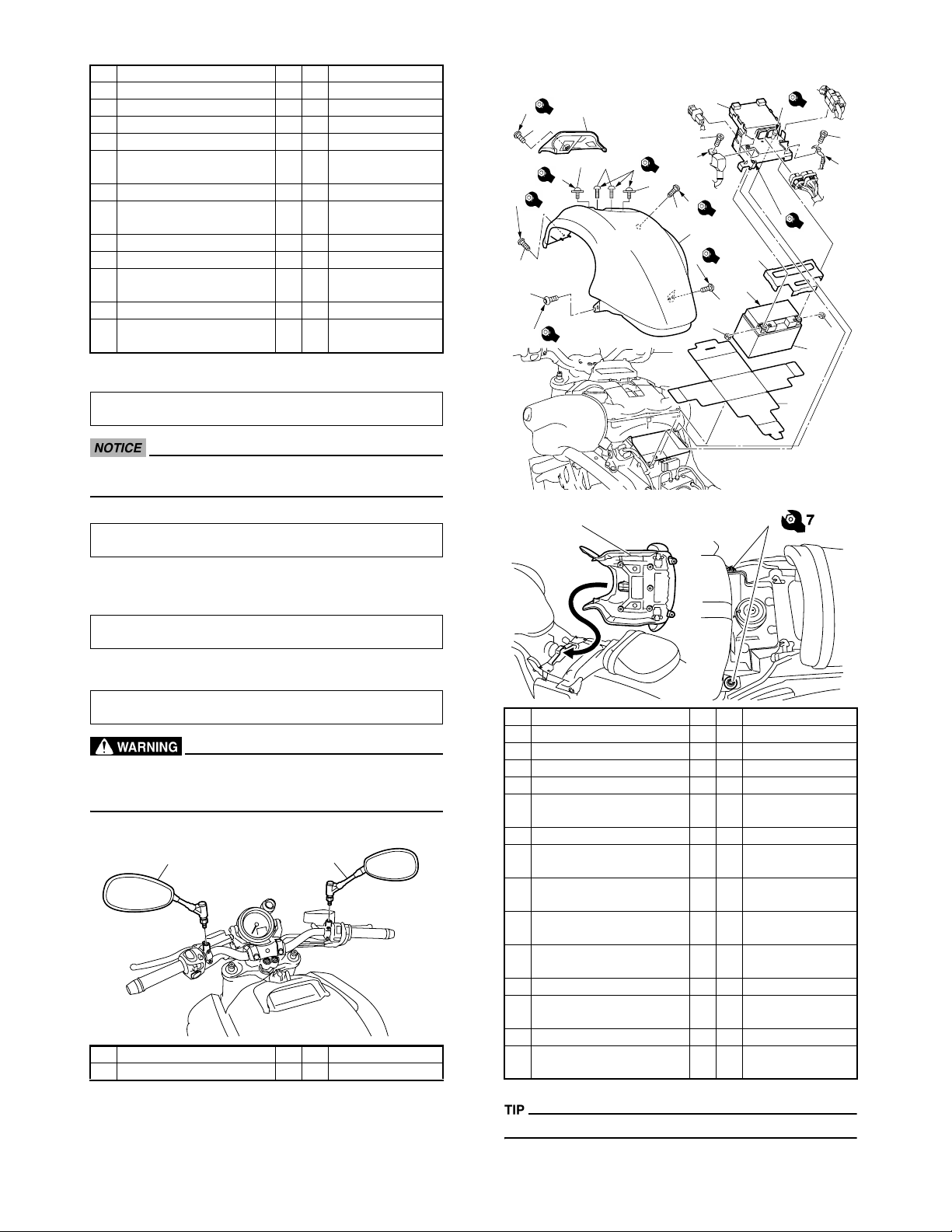
4. BATTERY
G
7
12
13
11
F
7
F
7
9
8
E
1.5
10
5
6
F
C
7
B
3
6
D
11
F
7
9
7
E
1.5
B
3
3
A
8
4
4
2
1
C: Tighten the bolts to specification.
Bolt
10 Nm (1.0 m•kg, 7.2 ft•lb)
D: Fasten the front brake hose and front wheel sensor lead with
the front brake hose holder.
E: Tighten the bolt to specification.
Bolt
10 Nm (1.0 m•kg, 7.2 ft•lb)
F: Fasten the front brake hose with the front brake hose clamp.
G: Tighten the bolts to specification.
Bolt
10 Nm (1.0 m•kg, 7.2 ft•lb)
Proper cable routing is essential to assure safe vehicle operation.
Refer to "CABLE ROUTING".
3. REAR VIEW MIRRORS
1
1 Left rear view mirror 1 C
2 Right rear view mirror 1 C
2
2 *
15, H
d = 6 (0.24), L = 10
(0.39)
d = 6 (0.24), L = 20
(0.79)
d = 6 (0.24), L = 18
(0.71)
d = 6 (0.24), L = 10
(0.39)
d = 6 (0.24), L = 12
(0.47)
d = 6 (0.24), L = 10
(0.39)
d = 6 (0.24), L = 30
(1.18)
14
1 Battery seat 1 *
2 Battery 1 *
3 Rubber damper 1 *
4Nut 2 * d = 6 (0.24)
5 Battery cover 1 *
6Bolt 2 *
7 Top cover 1 *
8 Hexagon socket bolt 2 *
9 Hexagon socket bolt 2 *
10 Hexagon socket bolt 2 *
Hexagon socket bolt with
11
plain washer
12 Multi-function display cover 1 *
13 Hexagon socket bolt 1 *
14 Rider seat 1 *
15 Hexagon socket bolt 2 *
A: Installing the battery.
Refer to "ADJUSTMENTS AND PREDELIVERY SERVICE".
-7-
B: Tighten the bolts to specification.
Bolt
3 Nm (0.3 m•kg, 2.2 ft•lb)
C: First, connect the positive lead (red lead) to the positive ter-
minal.
D: Second, connect the negative lead (black lead) to the nega-
tive terminal.
Refer to "CABLE ROUTING".
E: Tighten the bolts to specification.
Bolt
1.5 Nm (0.15 m•kg, 1.1 ft•lb)
F: Tighten the bolts to specification.
Bolt
7 Nm (0.7 m•kg, 5.1 ft•lb)
G: Tighten the bolt to specification.
Bolt
7 Nm (0.7 m•kg, 5.1 ft•lb)
H: Tighten the bolts to specification.
Bolt
7 Nm (0.7 m•kg, 5.1 ft•lb)
-8-
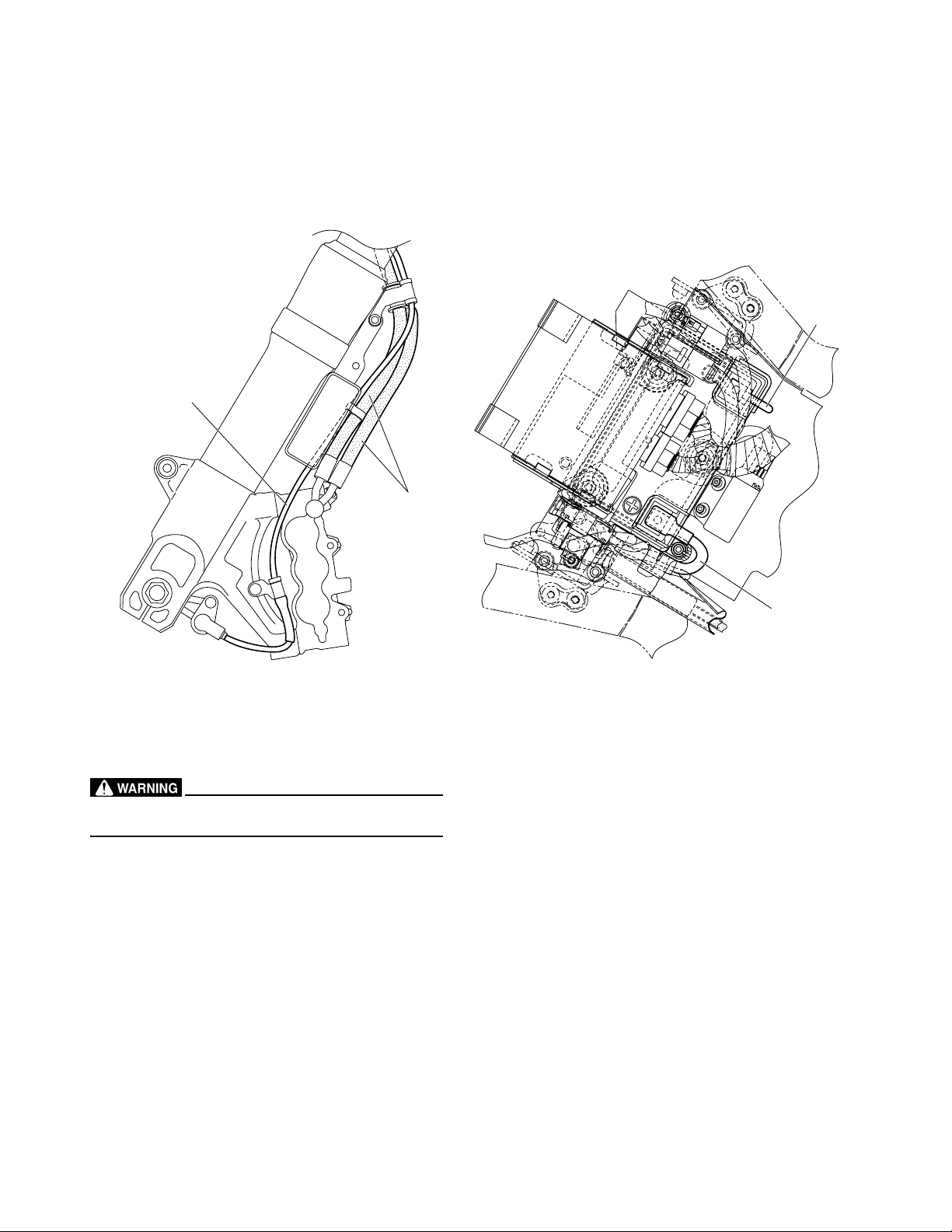
CABLE ROUTING
3
1
2
Proper cable and lead routing are essential to insure safe vehicle operation.
1. Front wheel sensor lead
2. Front brake hose
3. Negative battery lead
4. Positive battery lead
4
-9-
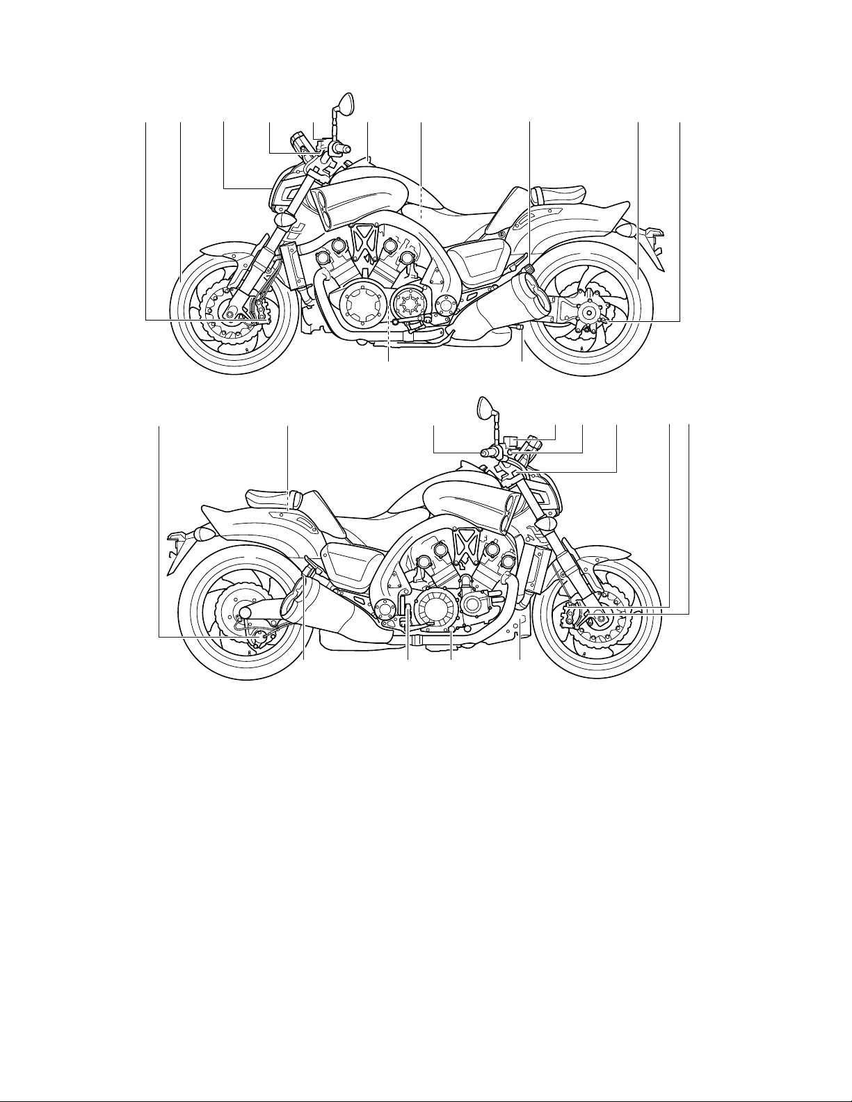
ADJUSTMENTS AND PREDELIVERY SERVICE
Perform the predelivery service in the order indicated by the letters. Always follow the order as shown.
B P AO
M
J
I
F
O
I
G
B DJ KL Q
NN
J
-10-
CO H
E
A. CHECKING AND CHARGING
THE BATTERY
The battery used in this vehicle is a VRLA
(Valve Regulated Lead Acid) battery, it has
been pre-filled with electrolyte at the factory so there is no need to add fluid at any
time.
1. Check:
Using a digital volt meter, the state of a
discharged VRLA (Valve Regulated
Lead Acid) battery can be checked by
measuring open-circuit voltage (the
voltage measured with the positive and
negative terminals being disconnected).
Open-circuit voltage
12.8 V or higher
Charging time
Charging is not necessary
• Do not attempt boost charging under
any circumstances.
• Battery electrolyte is poisonous and
dangerous, causing severe burns,
etc. It contains sulfuric acid. Avoid
contact with skin, eyes or clothing.
Antidote: External -Flush with water.
Internal-Drink large quantities of water or milk. Follow with milk of magnesia, beaten egg, or vegetable oil. Call
physician immediately.
Eyes: Flush with water for 15 minutes
and get prompt medical attention.
Batteries produce explosive gases.
Keep sparks, flame, cigarettes, etc.,
away. Ventilate when charging or using in enclosed space. Always shield
eyes when working near batteries.
KEEP OUT OF THE REACH OF CHILDREN.
• If the voltage is lower than 12.8 V the
battery must be charged. If this is not
done, the life of the battery will be
shortened drastically. Refer to the
service manual for battery charging
instructions.
• Never remove the strip of caps, nor
add any water or electrolyte.
B. MEASURING THE TIRE
PRESSURE
1. Measure:
• tire pressure
Out of specification → Adjust.
• The tire pressure and the suspension
must be adjusted according to the total weight (including cargo, rider, passenger, and accessories) and the
anticipated riding speed.
• Operation of an overloaded vehicle
could cause tire damage, an accident,
or an injury.
NEVER OVERLOAD THE VEHICLE.
Basic weight:
With oil and full fuel tank
310 kg (683 lb)
Maximum load*
190 kg (419 lb)
Cold tire pressure
Up to 90 kg (198 lb) load*
Front
250 kPa (2.50 kgf/cm
Rear
290 kPa (2.90 kgf/cm
90kg (198 lb)–Maximum load*
Front
250 kPa (2.50 kgf/cm
Rear
290 kPa (2.90 kgf/cm
High speed riding
Front
290 kPa (2.90 kgf/cm
Rear
290 kPa (2.90 kgf/cm
* Load is the total weight of cargo, rider,
passenger and accessories.
2
, 36 psi)
2
, 42 psi)
2
, 36 psi)
2
, 42 psi)
2
, 42 psi)
2
, 42 psi)
C. CHECKING THE ENGINE OIL
LEVEL
1. Stand the vehicle on a level surface.
• Place the vehicle on a suitable stand.
• Make sure that the vehicle is upright.
2. Let the engine idle for a few minutes,
and then turn it off.
3. Check:
• engine oil level
The engine oil level should be between
the minimum level mark (a) and maximum level mark (b).
Below the minimum level mark → Add
the recommended engine oil to the
proper level.
Before checking the engine oil level, wait a
few minutes until the oil has settled.
b
a
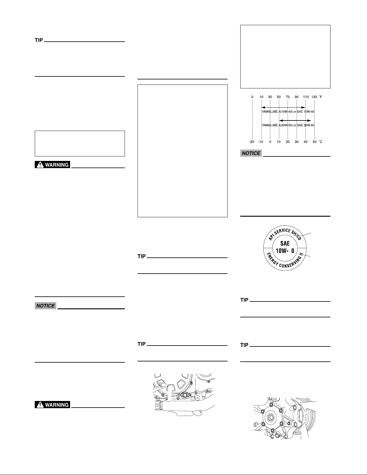
Recommended engine oil type
YAMALUBE 4 (10W-40) or SAE 10W40, YAMALUBE 4 (20W-50) or SAE
20W-50
Recommended engine oil grade
API service SG type or higher, JASO
standard MA
Quantity
Without oil filter cartridge replacement
4.30 L (3.78 Imp qt, 4.55 US qt)
• Engine oil also lubricates the clutch
and the wrong oil types or additives
could cause clutch slippage. Therefore, do not add any chemical additives or use engine oils with a grade of
CD (c) or higher and do not use oils labeled "ENERGY CONSERVING II" (d).
• Do not allow foreign materials to enter
the crankcase.
c
4
d
4. Start the engine, warm it up for several
minutes, and then turn it off.
5. Check the engine oil level again.
Before checking the engine oil level, wait a
few minutes until the oil has settled.
D. CHECKING THE FINAL GEAR
OIL LEVEL
1. Stand the vehicle on a level surface.
• Place the vehicle on a suitable stand.
• Make sure that the vehicle is upright.
2. Check:
• final gear oil level
a. Loosen the final gear oil check bolt (1)
until oil flows out.
• The tire pressure should only be
checked and regulated when the tire
temperature equals the ambient air
temperature.
1
-11-
 Loading...