

Yamaha TDM900P 2002 Service Manual


EAS00000
TDM900 (P) 2002
SERVICE MANUAL
2001 by Yamaha Motor Co., Ltd.
First edition, November 2001
All rights reserved.
Any reproduction or unauthorized use
without the written permission of
Yamaha Motor Co., Ltd.
is expressly prohibited.

EAS00002
NOTICE
This manual was produced by the Yamaha Motor Company, Ltd. primarily for use by Yamaha dealers
and their qualified mechanics. It is not possible to include all the knowledge of a mechanic in one manual. Therefore, anyone who uses this book to perform maintenance and repairs on Yamaha vehicles
should have a basic understanding of mechanics and the techniques to repair these types of vehicles.
Repair and maintenance work attempted by anyone without this knowledge is likely to render the vehicle unsafe and unfit for use.
Yamaha Motor Company, Ltd. is continually striving to improve all of its models. Modifications and significant changes in specifications or procedures will be forwarded to all authorized Yamaha dealers
and will appear in future editions of this manual where applicable.
NOTE:
Designs and specifications are subject to change without notice.
EAS00004
IMPORTANT MANUAL INFORMATION
Particularly important information is distinguished in this manual by the following.
The Safety Alert Symbol means ATTENTION! BECOME ALERT! YOUR
SAFETY IS INVOLVED!
WARNING
CAUTION:
NOTE: A NOTE provides key information to make procedures easier or clearer.
Failure to follow WARNING instructions could result in severe injury or death to
the motorcycle operator, a bystander or a person checking or repairing the motorcycle.
A CAUTION indicates special precautions that must be taken to avoid damage
to the motorcycle.
EAS00007
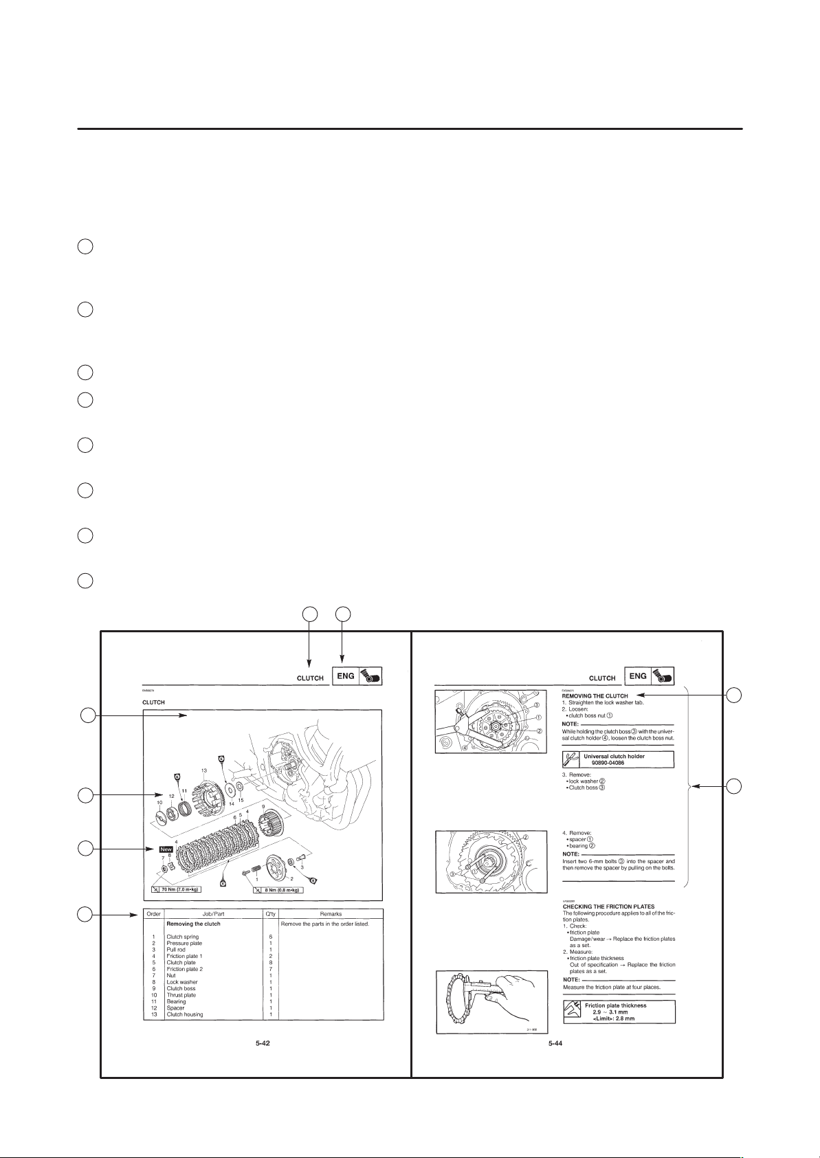
HOW TO USE THIS MANUAL
This manual is intended as a handy, easy-to-read reference book for the mechanic. Comprehensive
explanations of all installation, removal, disassembly, assembly, repair and check procedures are laid
out with the individual steps in sequential order.
1
The manual is divided into chapters. An abbreviation and symbol in the upper right corner of each
page indicate the current chapter.
Refer to “SYMBOLS”.
2
Each chapter is divided into sections. The current section title is shown at the top of each page,
except in Chapter 3 (“PERIODIC CHECKS AND ADJUSTMENTS”), where the sub-section title(s) appears.
3
Sub-section titles appear in smaller print than the section title.
4
To help identify parts and clarify procedure steps, there are exploded diagrams at the start of each
removal and disassembly section.
5
Numbers are given in the order of the jobs in the exploded diagram. A circled number indicates a
disassembly step.
6
Symbols indicate parts to be lubricated or replaced.
Refer to “SYMBOLS”.
7
A job instruction chart accompanies the exploded diagram, providing the order of jobs, names of
parts, notes in jobs, etc.
8
Jobs requiring more information (such as special tools and technical data) are described sequentially.
12
4
5
6
7
3
8
1
GEN
INFO
3
CHK
ADJ
5
ENG
7
2
SPEC
4
CHAS
6
COOL
8
EAS00008
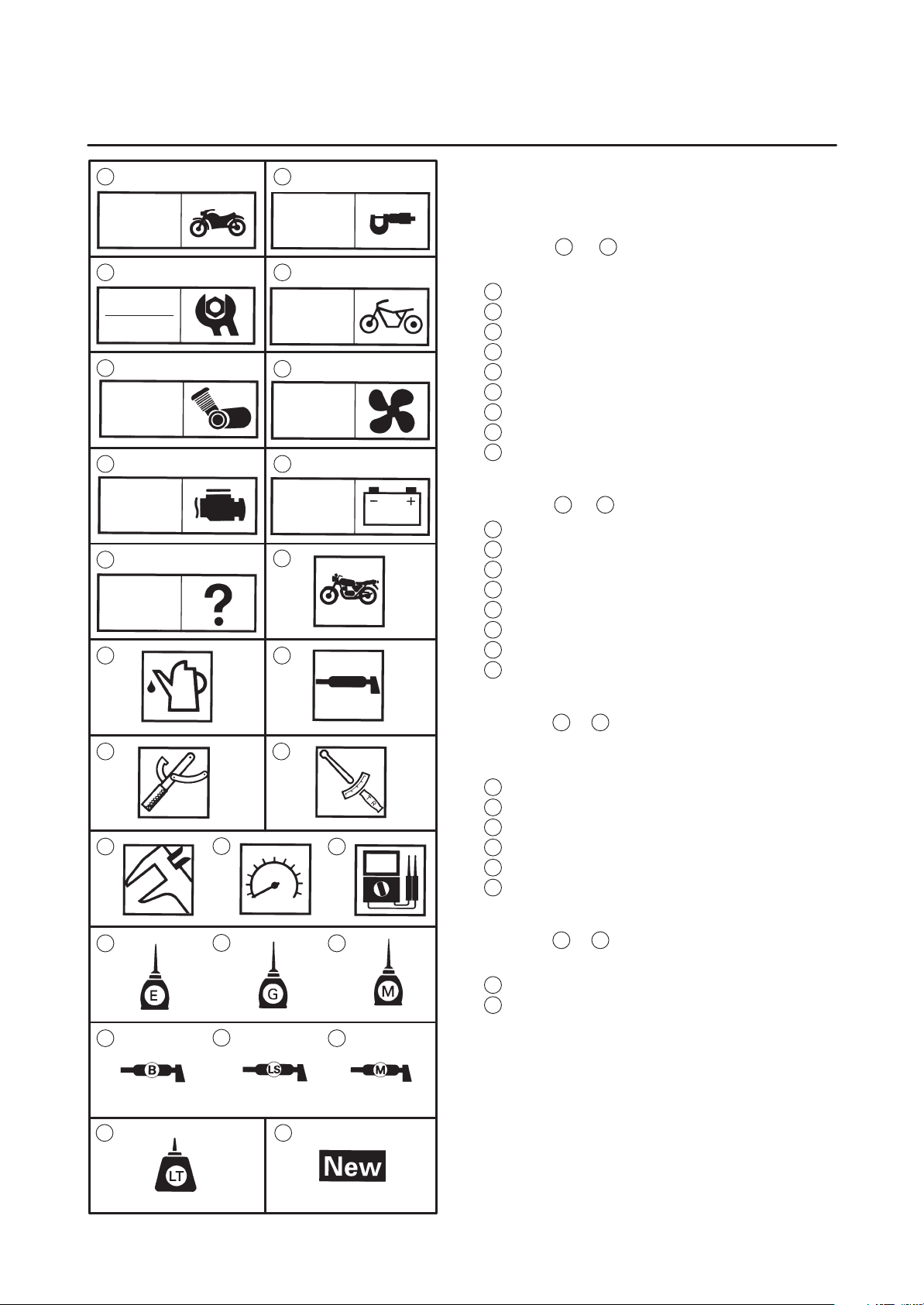
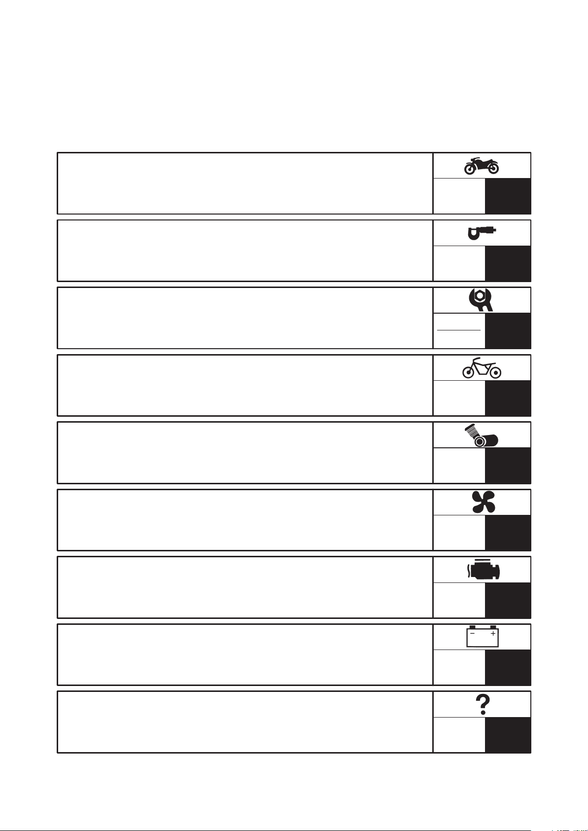
SYMBOLS
The following symbols are not relevant to every
vehicle.
Symbols
chapter.
1
General information
2
Specifications
3
Periodic checks and adjustments
4
Chassis
5
Engine
6
Cooling system
7
Fuel injection system
8
Electrical system
9
Troubleshooting
1
to 9 indicate the subject of each
FI ELEC
9
10
TRBL
SHTG
11 12
1413
16 1715
19 2018
Symbols
10
Serviceable with engine mounted
11
Filling fluid
12
Lubricant
13
Special tool
14
Tightening torque
15
Wear limit, clearance
16
Engine speed
17
Electrical data
Symbols
10
to 17 indicate the following.
18
to 23 in the exploded diagrams indicate the types of lubricants and lubrication
points.
18
Engine oil
19
Gear oil
20
Molybdenum-disulfide oil
21
Wheel-bearing grease
22
Lithium-soap- based grease
23
Molybdenum-disulfide grease
Symbols
24
to 25 in the exploded diagrams indicate the following.
24
Apply locking agent (LOCTITE))
25
Replace the part
22
24 25
2321
EAS00012
TABLE OF CONTENTS
GENERAL INFORMATION
SPECIFICATIONS
PERIODIC CHECKS AND
ADJUSTMENTS
CHASSIS
ENGINE
GEN
INFO
SPEC
CHK
ADJ
CHAS
ENG
1
2
3
4
5
COOLING SYSTEM
FUEL INJECTION SYSTEM
ELECTRICAL SYSTEM
TROUBLESHOOTING
COOL
FI
ELEC
TRBL
SHTG
6
7
8
9


GEN
INFO
CHAPTER 1
GENERAL INFORMATION
MOTORCYCLE IDENTIFICATION 1-1. . . . . . . . . . . . . . . . . . . . . . . . . . . . . . .
VEHICLE IDENTIFICATION NUMBER 1-1. . . . . . . . . . . . . . . . . . . . . . . . .
MODEL LABEL 1-1. . . . . . . . . . . . . . . . . . . . . . . . . . . . . . . . . . . . . . . . . . . . .
FEATURES 1-2. . . . . . . . . . . . . . . . . . . . . . . . . . . . . . . . . . . . . . . . . . . . . . . . . . .
OUTLINE 1-2. . . . . . . . . . . . . . . . . . . . . . . . . . . . . . . . . . . . . . . . . . . . . . . . . .
FI SYSTEM 1-3. . . . . . . . . . . . . . . . . . . . . . . . . . . . . . . . . . . . . . . . . . . . . . . .
ECU (Electronic Control Unit) 1-5. . . . . . . . . . . . . . . . . . . . . . . . . . . . . . . . .
THREE-WAY CATALYTIC CONVERTER SYSTEM 1-17. . . . . . . . . . . . . .
AIR INDUCTION SYSTEM 1-19. . . . . . . . . . . . . . . . . . . . . . . . . . . . . . . . . . .
INSTRUMENT PANEL 1-21. . . . . . . . . . . . . . . . . . . . . . . . . . . . . . . . . . . . . . .
IMPORTANT INFORMATION 1-23. . . . . . . . . . . . . . . . . . . . . . . . . . . . . . . . . . . .
PREPARATION FOR REMOVAL AND DISASSEMBLY 1-23. . . . . . . . . .
REPLACEMENT PARTS 1-23. . . . . . . . . . . . . . . . . . . . . . . . . . . . . . . . . . . . .
GASKETS, OIL SEALS AND O-RINGS 1-23. . . . . . . . . . . . . . . . . . . . . . . .
LOCK WASHERS/ PLATES AND COTTER PINS 1-24. . . . . . . . . . . . . . . .
BEARINGS AND OIL SEALS 1-24. . . . . . . . . . . . . . . . . . . . . . . . . . . . . . . . .
CIRCLIPS 1-24. . . . . . . . . . . . . . . . . . . . . . . . . . . . . . . . . . . . . . . . . . . . . . . . . .
CHECKING THE CONNECTIONS 1-25. . . . . . . . . . . . . . . . . . . . . . . . . . . . . . .
SPECIAL TOOLS 1-26. . . . . . . . . . . . . . . . . . . . . . . . . . . . . . . . . . . . . . . . . . . . . .

GEN
INFO
MOTORCYCLE IDENTIFICATION
EAS00014
GENERAL INFORMATION
MOTORCYCLE IDENTIFICATION
EAS00017
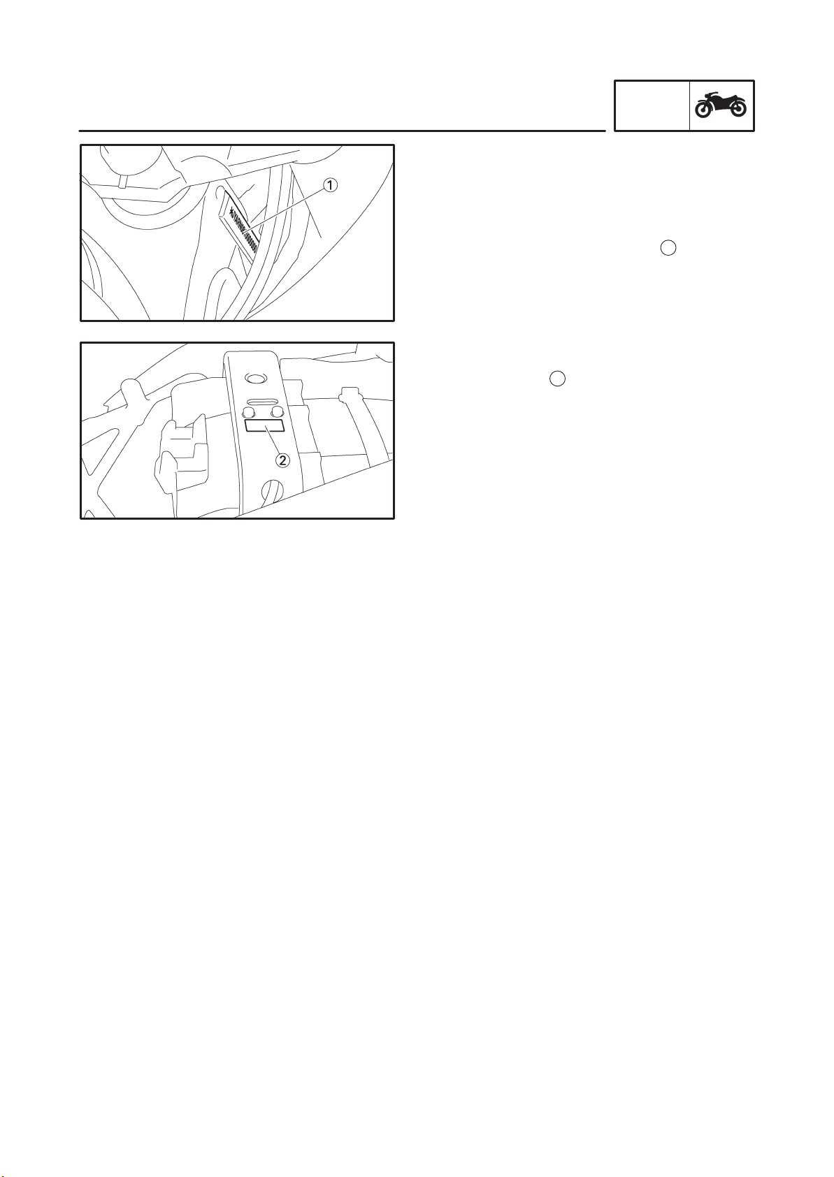
VEHICLE IDENTIFICATION NUMBER
The vehicle identification number
into the right side of the steering head pipe.
EAS00018
MODEL LABEL
2
The model label
information will be needed to order spare parts.
is affixed to the frame. This
GEN
INFO
1
is stamped
1-1
GEN
FEATURES
FEATURES
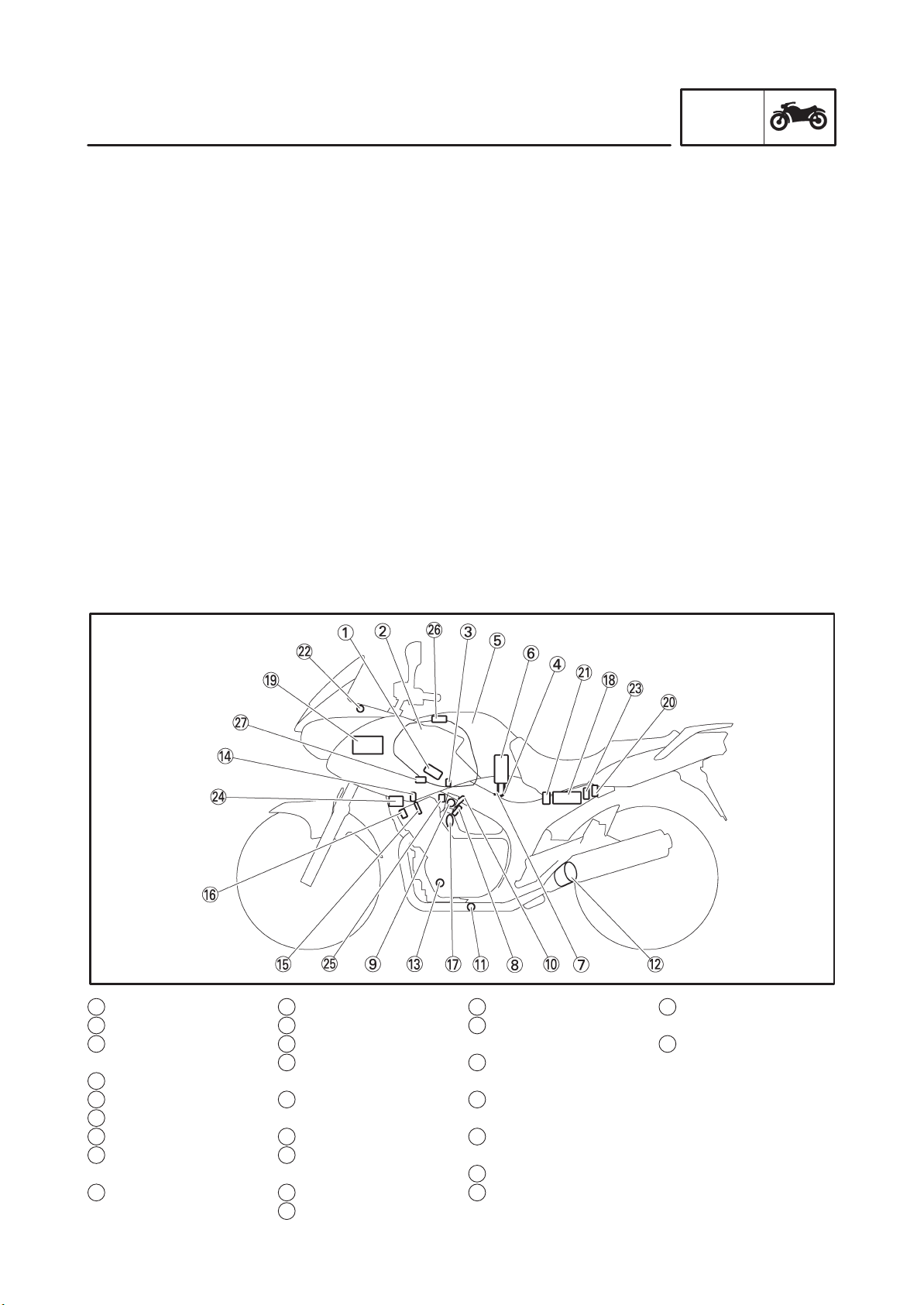
OUTLINE
The main function of a fuel supply system is to provide fuel to the combustion chamber at the optimum
air-fuel ratio in accordance with the engine operating conditions and the atmospheric temperature.
In the conventional carburetor system, the air-fuel ratio of the mixture that is supplied to the combustion
chamber is created by the volume of the intake air and the fuel that is metered by the jet that is used in
the respective chamber.
Despite the same volume of intake air, the fuel volume requirement varies by the engine operating
conditions, such as acceleration, deceleration, or operating under a heavy load. Carburetors that meter the fuel through the use of jets have been provided with various auxiliary devices, so that an optimum air-fuel ratio can be achieved to accommodate the constant changes in the operating conditions
of the engine.
As the requirements for the engine to deliver more performance and cleaner exhaust gases increase, it
becomes necessary to control the air-fuel ratio in a more precise and finely tuned manner. To accommodate this need, this model has adopted an electronically controlled fuel injection (FI) system, in
place of the conventional carburetor system. This system can achieve an optimum air-fuel ratio required by the engine at all times by using a microprocessor that regulates the fuel injection volume
according to the engine operating conditions detected by various sensors.
The adoption of the FI system has resulted in a highly precise fuel supply, improved engine response,
better fuel economy, and reduced exhaust emissions. Furthermore, the air induction system (AI system) has been placed under computer control together with the FI system in order to realize cleaner
exhaust gases.
INFO
1 Ignition coil
2 Air filter case
3 Intake air temperature
sensor
4 Fuel delivery hose
5 Fuel tank
6 Fuel pump
7 Fuel return hose
8 Intake air pressure
sensor
9 Throttle position sen-
sor
10 Fuel injector
11 O
sensor
2
12 Catalytic converter
13 Crankshaft position
sensor
14 Coolant temperature
sensor
15 Spark plug
16 Cylinder identification
sensor
17 Pressure regulator
18 Battery
19 ECU
20 Atmospheric pressure
sensor
21 Fuel injection system
relay
22 Engine trouble warn-
ing light
23 Lean angle cut-off
switch
24 Air cut-off valve
25 Fast idle plunger
1-2
26 Adjustable air intake
duct
27 Intake solenoid
GEN
FEATURES
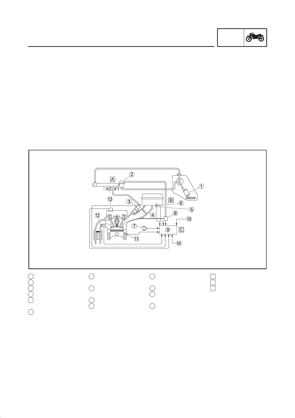
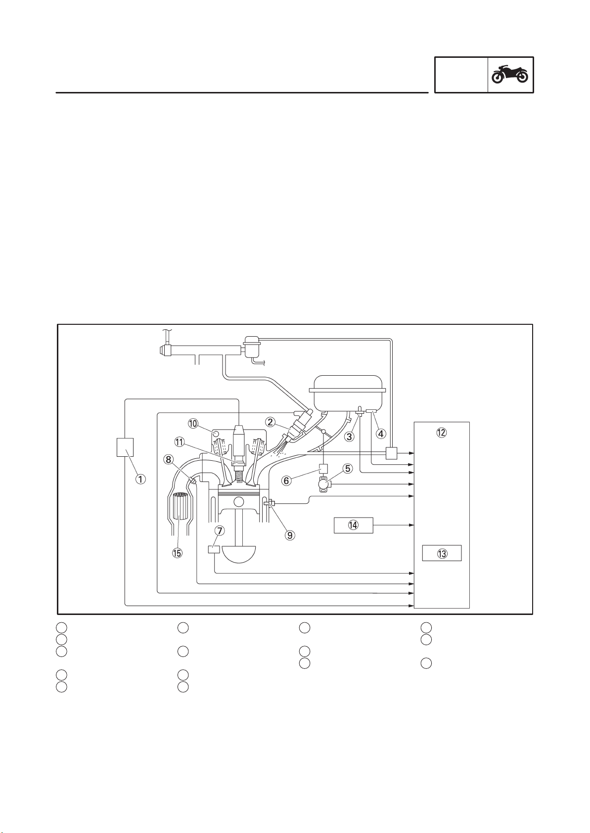
FI SYSTEM
The fuel pump delivers fuel to the injector via the fuel filter. The pressure regulator maintains the fuel
pressure that is applied to the injector at only 294 kPa (2.94 kg/cm
manifold pressure. Accordingly, when the energizing signal from the ECU energizes the injector, the
fuel passage opens, causing the fuel to be injected into the intake manifold only during the time the
passage remains open. Therefore, the longer the length of time the injector is energized (injection
duration), the greater the volume of fuel that is supplied. Conversely, the shorter the length of time the
injector is energized (injection duration), the lesser the volume of fuel that is supplied.
The injection duration and the injection timing are controlled by the ECU. Signals that are input from the
throttle position sensor, crankshaft position sensor, intake air pressure sensor, atmospheric pressure
sensor, intake temperature sensor, coolant temperature sensor, and O
termine the injection duration. The injection timing is determined through the signals from the crankshaft position sensor ands the cylinder identification sensor. As a result, the volume of fuel that is required by the engine can be supplied at all times in accordance with the driving conditions.
2
, 2.94 bar) higher than the intake
sensor enable the ECU to de-
2
INFO
1 Fuel pump
2 Pressure regulator
3 Fuel injector
4 Throttle body
5 Intake air temperature
sensor
6 Intake solenoid
7 Throttle position sen-
sor
8 Intake air pressure
sensor
9 ECU
10 Atmospheric pressure
sensor
11 Coolant temperature
sensor
12 O
sensor
2
13 Cylinder identification
sensor
14 Crankshaft position
sensor
1-3
A Fuel system
B Air system
C Control system
FEATURES
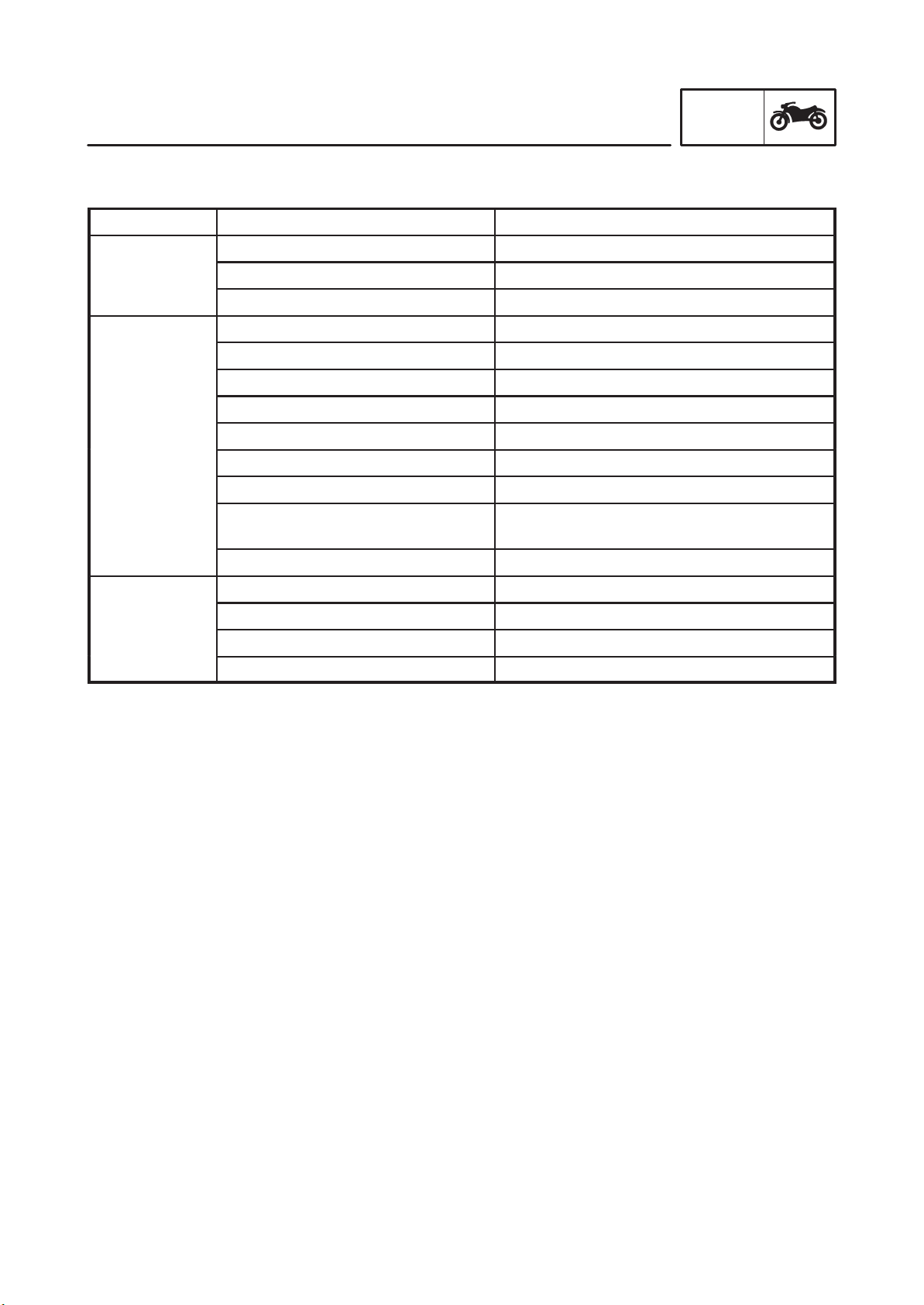
Fuel control block
The fuel control block consists of the following main components:
Component Function
GEN
INFO
Control block
Sensor block
Actuator block
ECU Total FI system control
Throttle body Air volume control
Pressure regulator Fuel pressure detection
Intake air pressure sensor Intake air pressure detection
Atmospheric pressure sensor Atmospheric pressure detection
Coolant temperature sensor Coolant temperature detection
Intake air temperature sensor Intake air temperature detection
Throttle position sensor Throttle angle detection
O2 sensor Gas emission O2 concentration detection
Cylinder identification sensor Reference position detection
Crankshaft position sensor Crankshaft position detection and engine
PRM detection
Speed sensor Speed detection
Injector Fuel injection
Fuel pump Fuel feed
Air induction system, air cut valve Induction of secondary air
Intake solenoid Air volume control
1-4
GEN
FEATURES
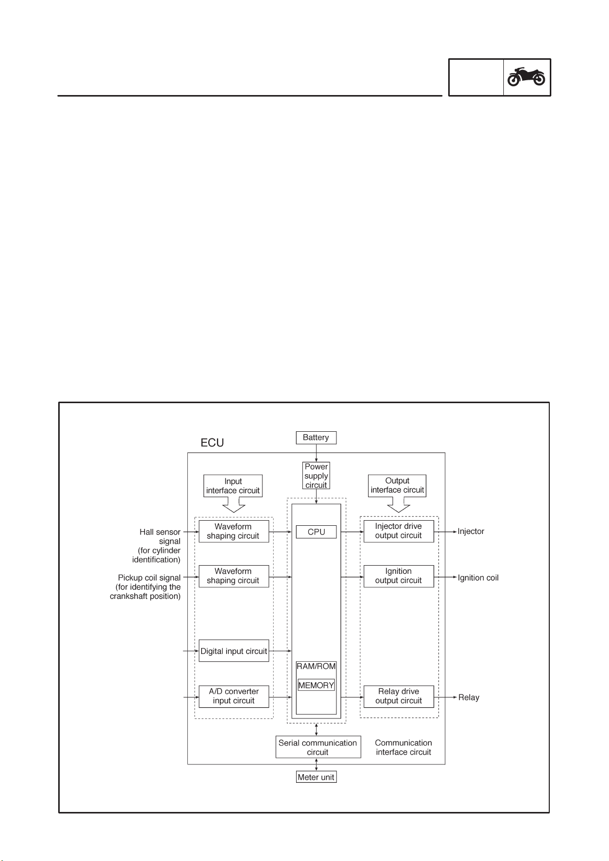
ECU (Electronic Control Unit)
The main functions of the ECU are ignition control, fuel control, self-diagnosis, and load control.
S ECU’s internal construction and functions
The main components and functions of the ECU can be broadly divided into the following four items:
A. Power supply circuit
The power supply circuit obtains power from the battery (12 V) to supply the power (5 V) that is
required for operating the ECU.
B. Input interface circuits
The input interface circuits convert the signals output by all the sensors into digital signals, which
can be processed by the CPU, and input them into the CPU.
C. CPU (Central Processing Unit)
The CPU determines the condition of the sensors in accordance with the level of the signal that is
output by the respective sensor. Then, the signals are temporarily stored on the RAM in the CPU.
Based on those stored signals and the basic processing program on the ROM, the CPU calculates
the fuel injection duration, injection timing, and ignition timing, and then sends control commands
to the respective output interface circuits.
D. Output interface circuits
The output interface circuits convert the control signals output by the CPU into actuating signals for
the respective actuators in order to actuate them. They also output commands to the relay output
circuits as needed.
E. Interface circuit for communication
Communicates with the meter.
INFO
Switches
Sensors
1-5

GEN
FEATURES
S Ignition control
The ignition control function of the ECU controls the ignition timing and the duration of ignition energizing. The ignition timing control uses the signals from the throttle position sensor (to detect the angle
of the throttle), and the crankshaft position sensor and speed sensor (to detect the speed of the engine). This control establishes an ignition timing that suits the operating condition of the engine
through compensations made to the basic ignition timing control map. The ignition energizing duration control establishes the energizing duration to suit the operating conditions by calculating the energizing duration in accordance with the signal received from the crankshaft position sensor and the
battery voltage.
S Fuel control
The fuel control function of the ECU controls the injection timing and injection duration. The injection
timing control controls the injection timing during the starting of the engine and the injection timing
during the normal operation of the engine, based on the signals received from the crankshaft position
sensor and the cylinder identification sensor. The injection duration control determines the duration of
injection based on the signals received from the atmospheric pressure sensors, temperature sensors, and the position sensors, to which compensations are made to suit various conditions such as
the weather, atmospheric pressure, starting, acceleration, and deceleration.
S Load control
The ECU effects load control in the following manner:
1. Stopping the fuel pump and injectors when the motorcycle overturns
The ECU turns OFF the fuel injection system relay when the lean angle cut-off switch is tripped.
2. Operating the headlight illumination relay
On the model for Europe, the ECU causes the headlight relay 2 to output a constant ON signal,
provided that the main switch is ON. On the model for Australia, the ECU controls the headlight
relay 2 in accordance with the engine speed as required by the daytime illumination specification.
3. Operating the radiator fan motor in accordance with the coolant temperature
The ECU controls the radiator fan motor relay ON/OFF in accordance with the coolant temperature.
4. Operating the AI system solenoid valve
The ECU controls the energizing of the solenoid valve in accordance with the driving conditions.
5. Operating the intake solenoid valve
The ECU controls the energizing of the solenoid valve in accordance with the driving conditions.
S Self-diagnosis function
The ECU is equipped with a self-diagnosis function to ensure that the engine control system is operating normally. The ECU mode functions include a diagnosis mode in addition to the normal mode.
Normal mode
S To check for any blown bulbs, this mode illuminates a warning light while the main switch is turned ON,
and while the starter switch is being pressed.
S If the starting disable warning is activated, this mode alerts the rider by blinking the warning light while
the start switch is being pressed.
S If a malfunction occurs in the system, this mode provides an appropriate substitute characteristic op-
eration, and alerts the rider of the malfunction by illuminating a warning light. After the engine is
stopped, this mode displays a fault code on the clock LCD.
Diagnosis mode
S In this mode, a diagnostic code is input into the ECU through the operation of the operating switch on
the meter, and the ECU displays the values output by the sensors or actuates the actuators in accor-
dance with the diagnostic code. Whether the system is operating normally can be checked by observ-
ing the illumination of the warning light, the values displayed on the meter, or the actuating state of the
actuators.
INFO
1-6
GEN
FEATURES
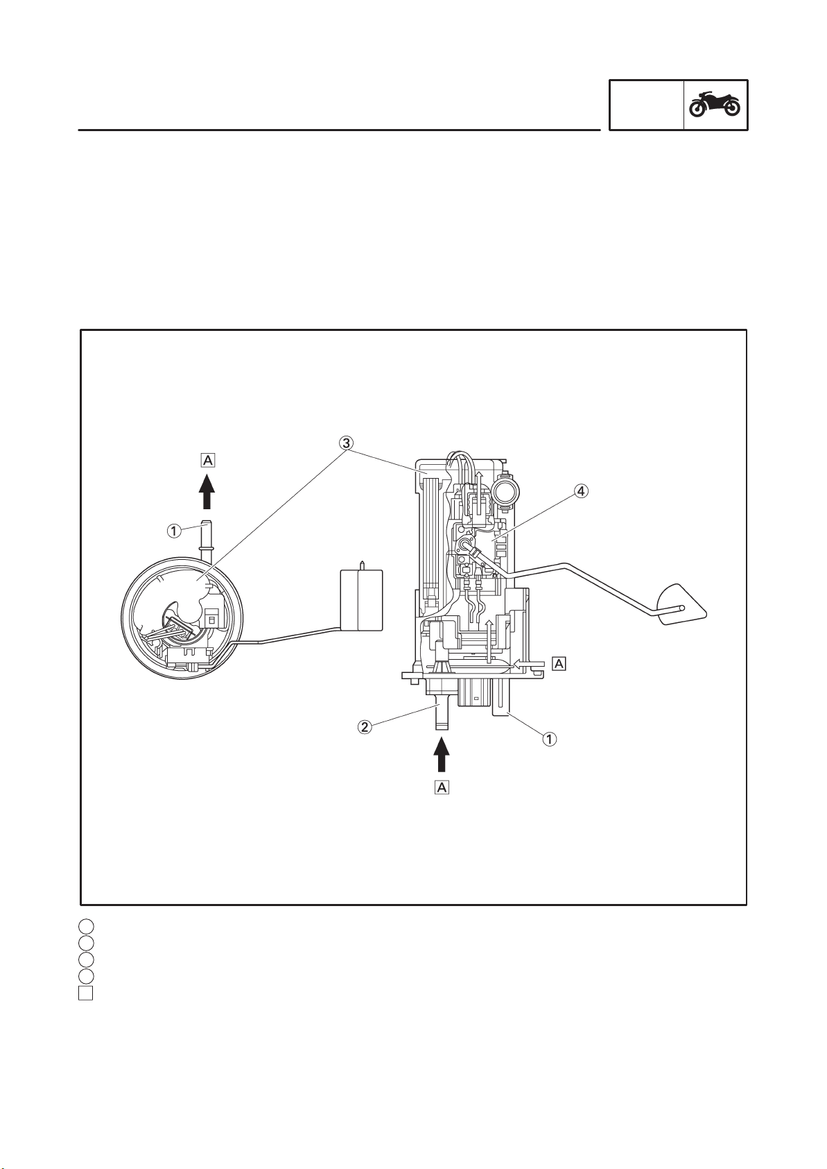
Fuel pump
The fuel pump, which is mounted in the fuel tank, draws the fuel directly from the tank and pumps it to
the injector.
A filter that is provided in the fuel pump prevents any debris in the fuel tank from entering the fuel system downstream of the pump.
The pump consists of a pump unit, electric motor, filter, and valves.
The pump unit is a Wesco type rotary pump that is connected to the motor shaft.
A relief valve is provided to prevent the fuel pressure from rising abnormally if the fuel hose becomes
clogged. This valve opens when the fuel pressure at the discharge outlet reaches between 441 and
637 kPa, and returns the fuel to the fuel tank.
INFO
1 Fuel feed nozzle
2 Fuel return nozzle
3 Fuel filter
4 Sender unit
A Fuel
1-7
GEN
FEATURES
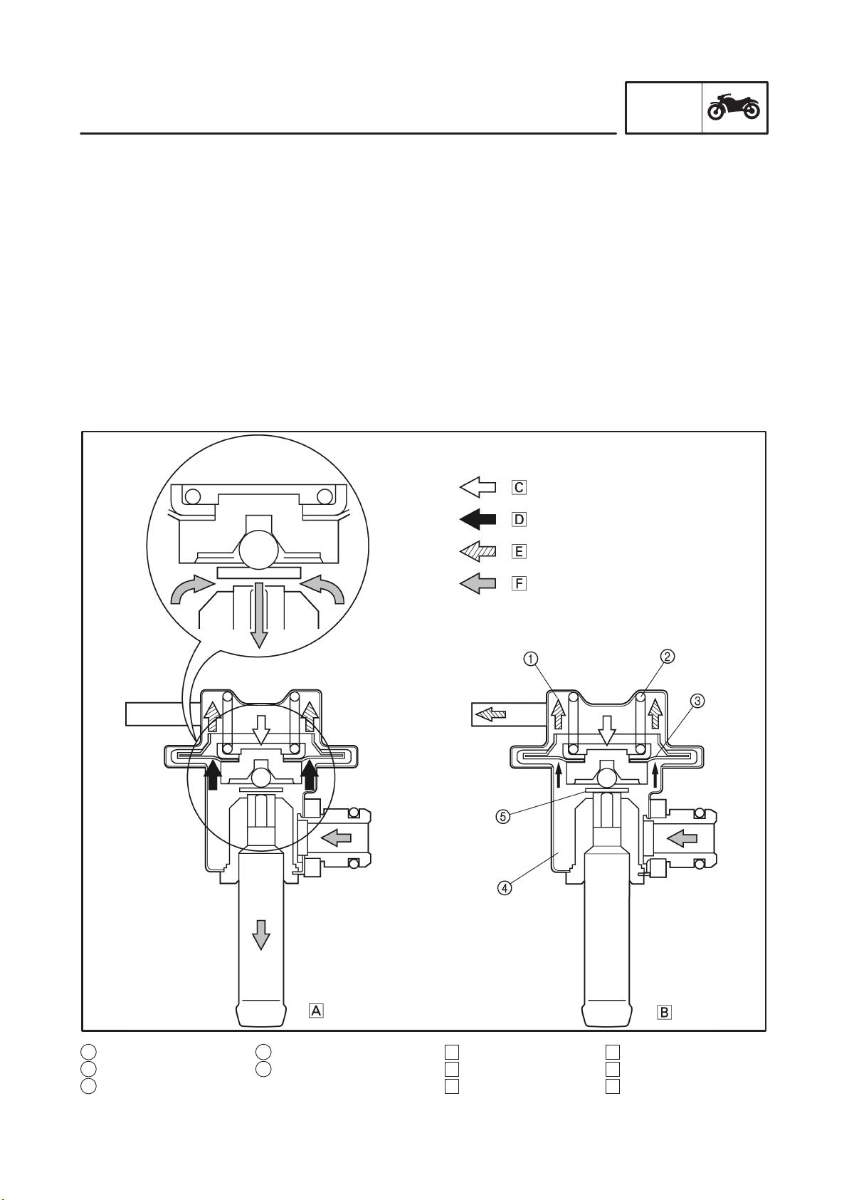
Pressure regulator
It regulates the fuel pressure that is applied to the injectors that are provided in the cylinders in order to
maintain a constant pressure difference with the pressure in the intake manifold.
The fuel that is delivered by the fuel pump fills the fuel chamber through the fuel inlet of the regulator
and exerts pressure on the diaphragm in the direction for opening the valve.
A spring that is provided in the spring chamber exerts pressure on the diaphragm in the direction for
closing the valve, in contrast to the pressure of the fuel. Thus, the valve cannot open unless the fuel
pressure overcomes the spring force.
An intake vacuum is applied to the spring chamber via a pipe. When the pressure of the fuel exceeds
the sum of the intake vacuum and the spring force, the valve that is integrated with the diaphragm
opens, allowing the fuel to return from the fuel outlet to the fuel tank, via the fuel return hose.
As a result, because the intake vacuum fluctuates in accordance with the changes in the operating
conditions in contrast to the constant volume of fuel supplied by the pump, the valve opening/closing
pressure also changes to regulate the return fuel volume. Thus, the difference between the fuel pressure and the intake manifold pressure remains constant at a prescribed pressure.
INFO
1 Spring chamber
2 Spring
3 Diaphragm
4 Fuel chamber
5 Valve
A Open
B Close
C Spring pressure
1-8
D Fuel pressure
E Vacuum pressure
F Fuel
GEN
FEATURES
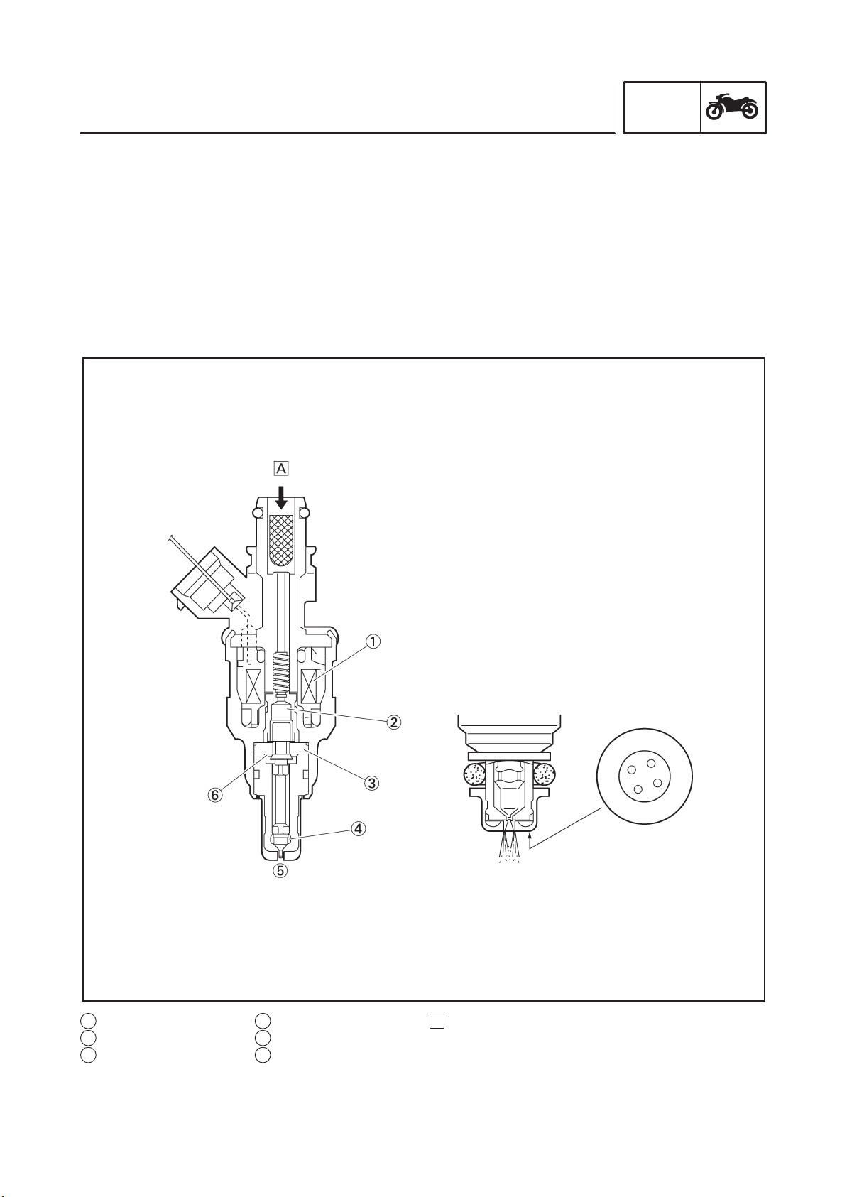
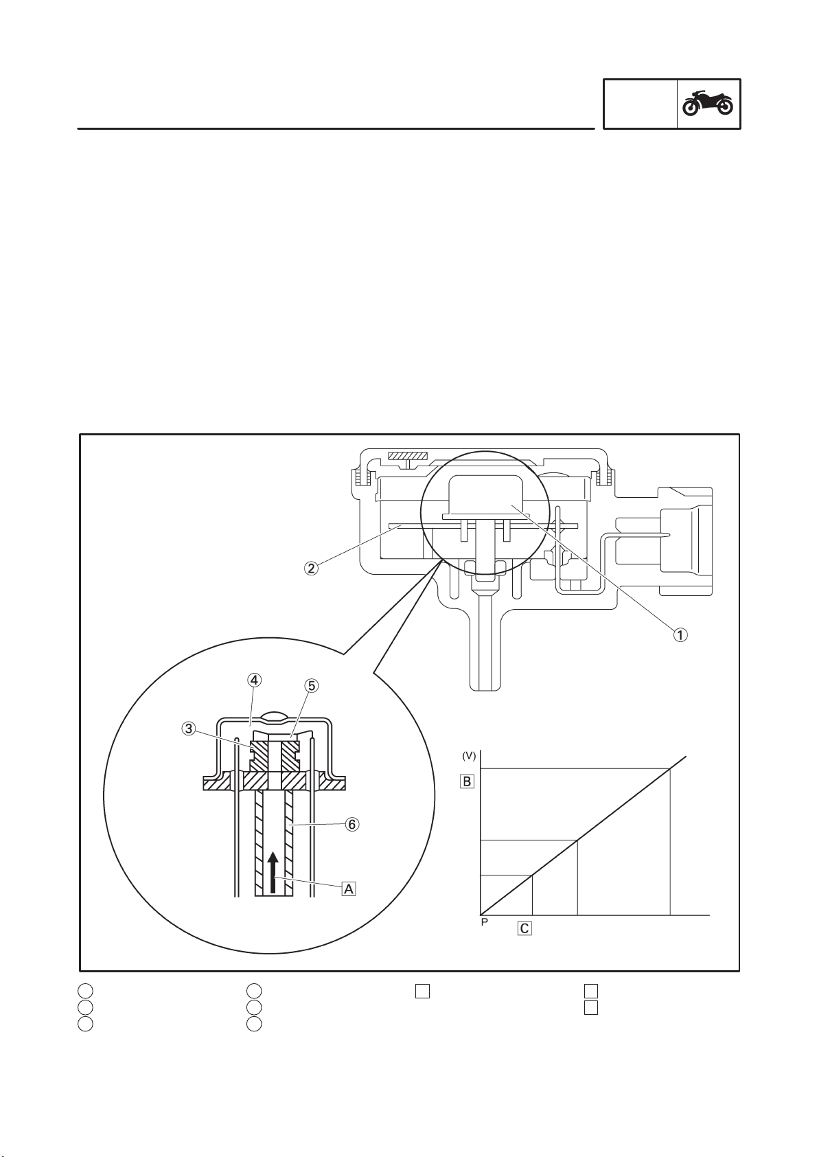
Fuel injector
Upon receiving injection signals from the ECU, the fuel injector injects fuel. In the normal state, the core
is pressed downward by the force of the spring, as illustrated. The needle that is integrated with the
bottom of the core keeps the fuel passage closed.
When the current flows to the coil in accordance with the signal from the ECU, the core is drawn upward, allowing the flange that is integrated with the needle to move to the spacer. Since the distance of
the movement of the needle is thus kept constant, the opening area of the fuel passage also becomes
constant. Because the pressure difference of the fuel to the intake manifold pressure is kept constant
by the pressure regulator, the fuel volume varies in proportion to the length of time the coil is energized.
The injector that has been recently adopted has a four-hole type injection orifice that enhances the
atomization of fuel and improves combustion efficiency.
INFO
1 Coil
2 Core
3 Spacer
A Fuel4 Needle
5 Inject
6 Flange
1-9
GEN
FEATURES
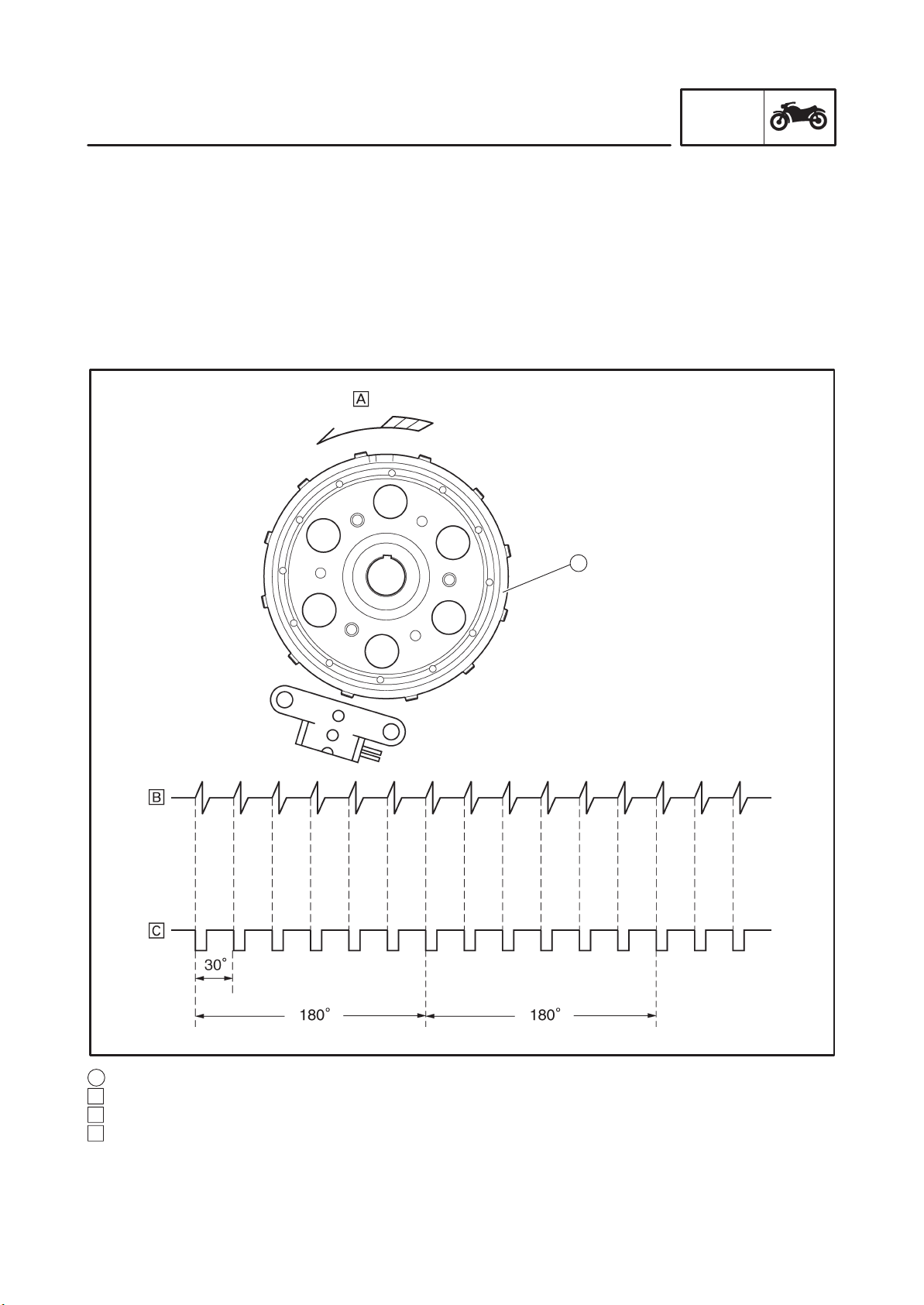
Crankshaft position sensor
The crankshaft position sensor uses the signals of the pickup coil that is mounted on the right side of
the crankshaft. When the rotation of the pickup rotor that is attached to the crankshaft causes the projections on the rotor to pass by the pickup coil, an electromotive force is generated in the coil.
The voltage of this force is then input into the ECU, which calculates the position of the crankshaft and
the speed of the engine. The ignition timing is then determined in accordance with the calculated data,
in order to determine the corresponding injection timing. Based on the changes in the time intervals of
the signals generated by the pickup coil, the ECU calculates the ignition timing advance to suit the operating conditions. The injection timing is also advanced in accordance with the ignition timing in order
to supply fuel to the engine at an optimal timing.
INFO
1
1 Pickup rotor
A Direction of rotation
B Pickup signal
C Trigger pole
1-10
GEN
FEATURES
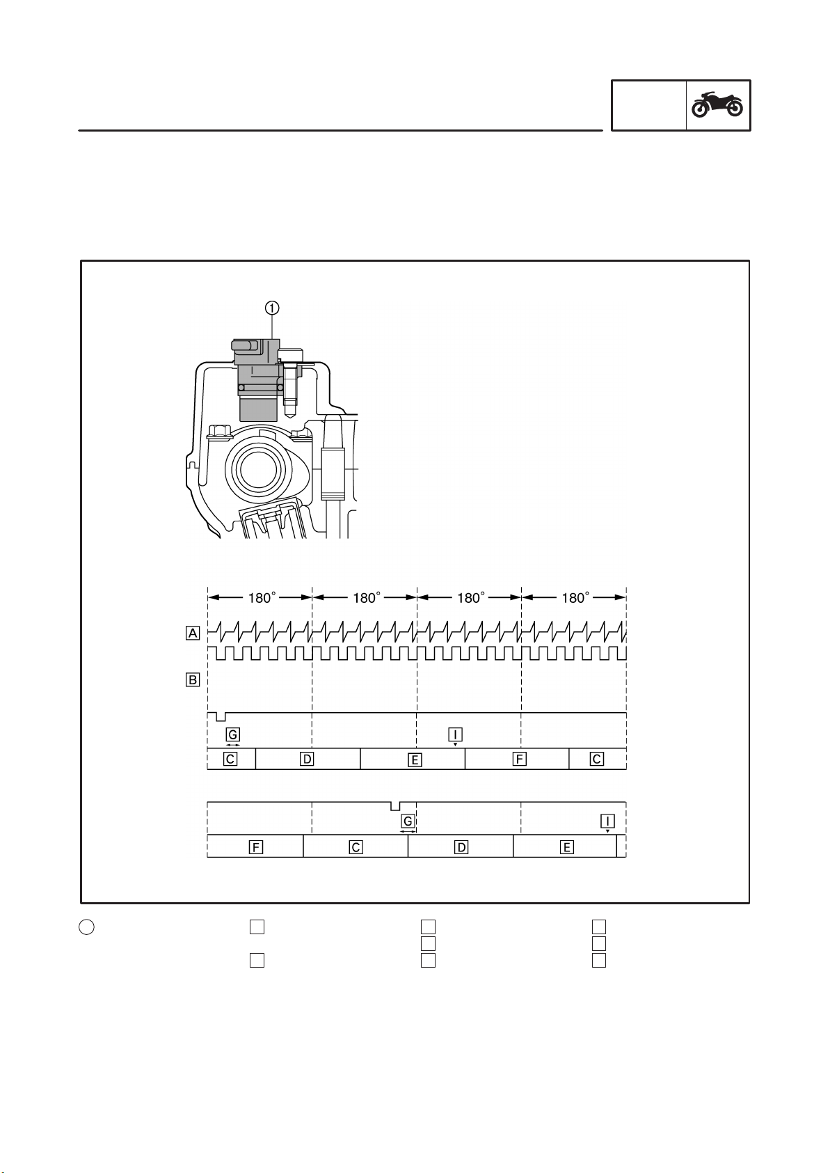
Cylinder identification sensor
The cylinder identification sensor is mounted on the exhaust head cover of the #1 cylinder. When the
exhaust cam of the #1 cylinder rotates and the projection of the cam plate passes by the sensor, the
sensor generates a signal and sends it to the ECU. Based on this signal and the signal from the crankshaft position sensor, the ECU then actuates the injector of the cylinder that is currently in order to supply fuel.
INFO
1 Cylinder identification
sensor
A Crankshaft position
sensor signal
B Cylinder identification
sensor signal
1-11
C Exhaust
D Intake
E Compression
F Combustion
G Injection
H Ignition
GEN
FEATURES
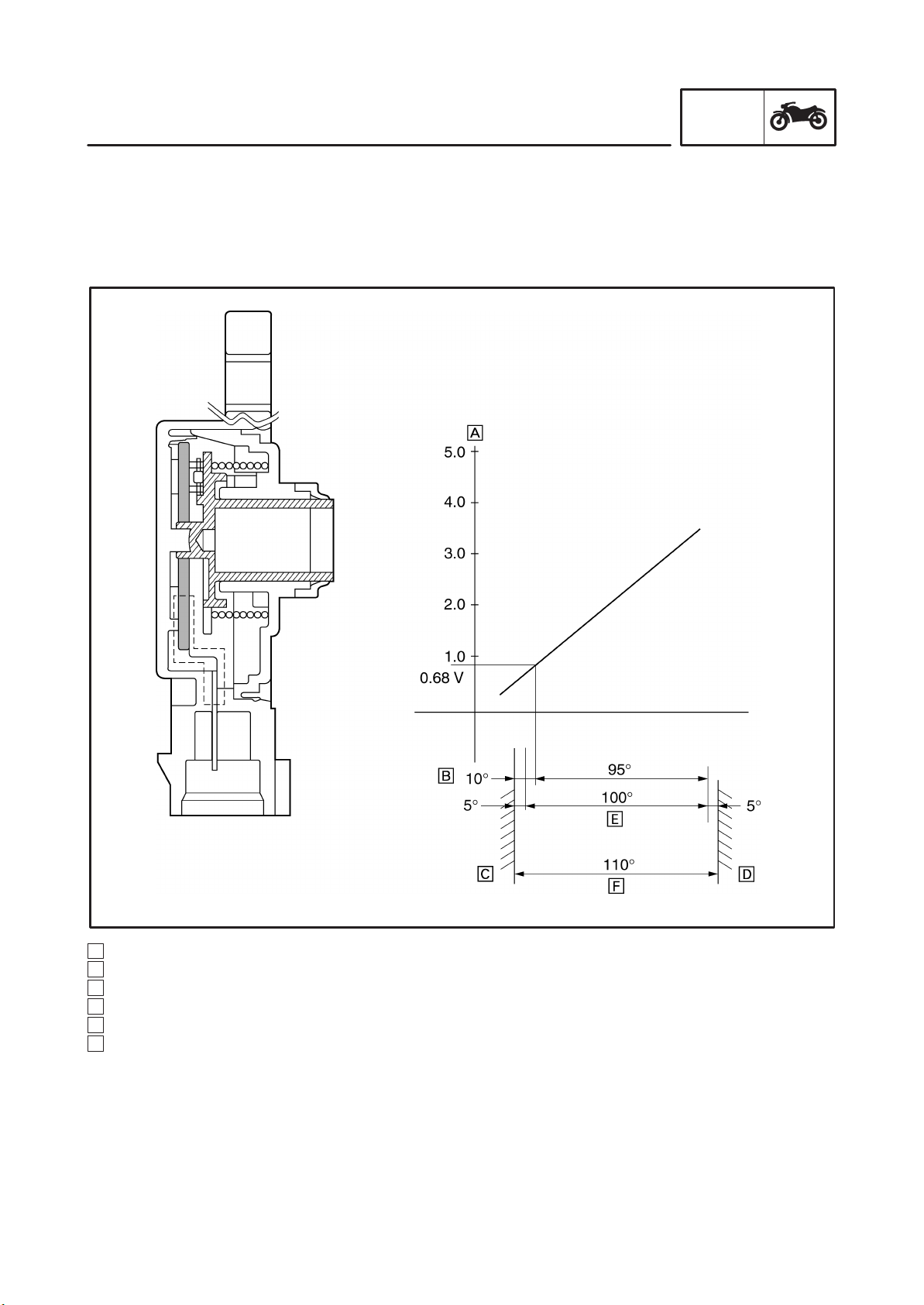
Throttle position sensor
The throttle position sensor measures the intake air volume by detecting the position of the throttle
valve. It detects the mechanical angle of the throttle valve through the positional relationship between
the moving contact that moves in unison with the throttle shaft and the resistor board. In actual operation, the ECU supplies 5 V power to both ends of the resistor board and the voltage that is output by the
throttle position sensor is used to determine the angle of the throttle valve.
INFO
A Output voltage
B Idling output position
C Mechanical stopper
D Mechanical stopper
E Effective electrical angle
F Sensor operating angle
1-12
GEN
FEATURES
Intake air pressure sensor and atmospheric pressure sensor
S Intake air pressure sensor
The intake air pressure sensor is used for measuring the intake air volume. The intake air volume of
every intake stroke is proportionate to the intake air pressure. Therefore, the intake air volume can
be measured by measuring the intake air pressure. The intake air pressure sensor converts the
measured intake air pressure into electrical signals and sends those signals to the ECU. When the
intake air pressure is introduced into the sensor unit, which contains a vacuum chamber on one side
of the silicon diaphragm, the silicon chip that is mounted on the silicon diaphragm converts the intake air pressure into electrical signals. Then, an integrated circuit (IC) amplifies and adjusts the
signals and makes temperature compensations, in order to generate electrical signals that are proportionate to the pressure.
S Atmospheric pressure sensor
The atmospheric pressure sensor is used for making compensations to the changes in the air density caused by the changes in the atmospheric pressure (particularly at high altitudes). The operating
principle and function of the atmospheric pressure sensor are the same as those of the aforementioned intake air pressure sensor.
INFO
1 Sensor unit
2 Hybrid IC
3 Silicon diaphragm
4 Vacuum chamber
5 Silicon chip
6 Pressure induction
pipe
A Atmospheric pressure,
intake air pressure
1-13
B Output voltage
C Input pressure
GEN
FEATURES
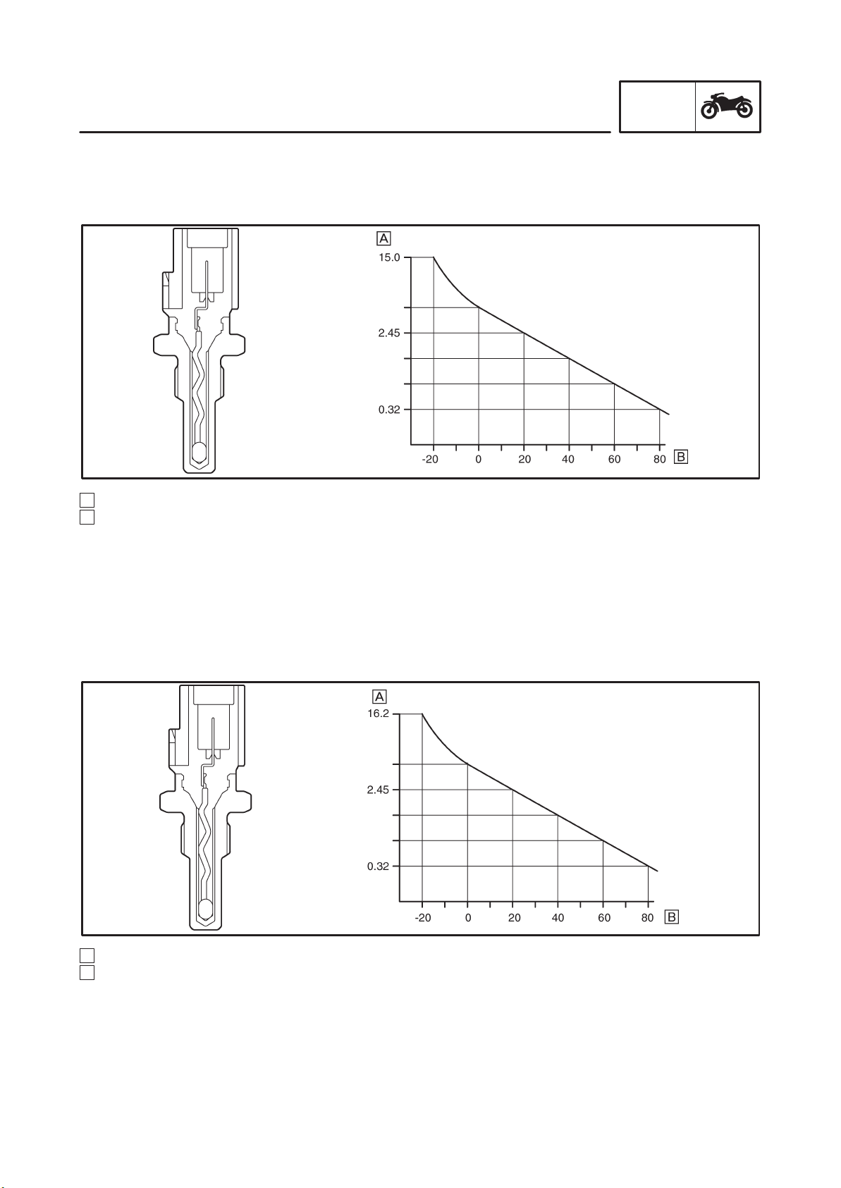
Coolant temperature sensor
The signals from the coolant temperature sensor are used primarily for making fuel volume compensations during starting and warm-up. The coolant temperature sensor converts the temperature of the
coolant into electrical signals and sends them to the ECU.
A Resistance kΩ
B Temperature _C
INFO
Intake air temperature sensor
The intake temperature sensor corrects the deviation of the air-fuel mixture that is associated with the
changes in the intake air density, which are created by the changes in the intake air temperature that
occur due to atmospheric temperatures. This sensor uses a semi-conductor thermistor that has a large
resistance at low temperatures and a small resistance at high temperatures. The thermistor converts
the temperature-dependent changes in resistance into electrical resistance values, which are then input into the ECU.
A Resistance kΩ
B Temperature _C
1-14
GEN
FEATURES
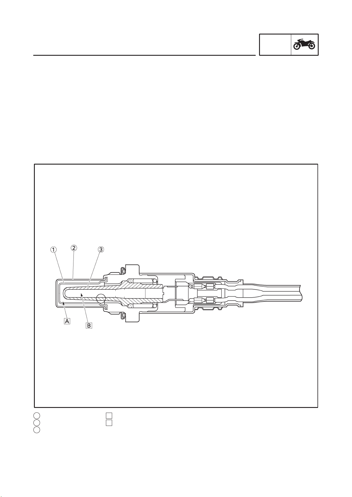
O2 sensor
The O
maintaining the air-fuel mixture near the stoichiometric ratio (14.7 : 1). This sensor, which is a zirconia
type, utilizes the oxygen ion conductivity of the solid electrolyte for detecting the oxygen concentration
levels. In actual operation, a zironia tube made of solid electrolyte is exposed in the exhaust gas, so
that the exterior of the zirconia tube is in contact with the exhaust gas and the interior is in contact with
the atmosphere whose oxygen concentration level is known. When a difference in the oxygen concentration level is created between the outside and the inside of the zirconia tube, the oxygen ion
passes through the zirconia element and generates an electromotive force. The electromotive force
increases when the oxygen concentration level is low (rich air-fuel ratio) and the electromotive force
decreases when the oxygen concentration level is high (lean air-fuel ratio). As electromotive force is
generated in accordance with the concentration of the exhaust gas, the resultant voltage is input into
the ECU in order to correct the duration of the injection of fuel.
sensor has been adopted to enable the catalyst to function at a high degree of efficiency by
2
INFO
1 Inner cover
2 Outer cover
3 Zirconia tube
A Exhaust gas
B Atmosphere
1-15
GEN
FEATURES
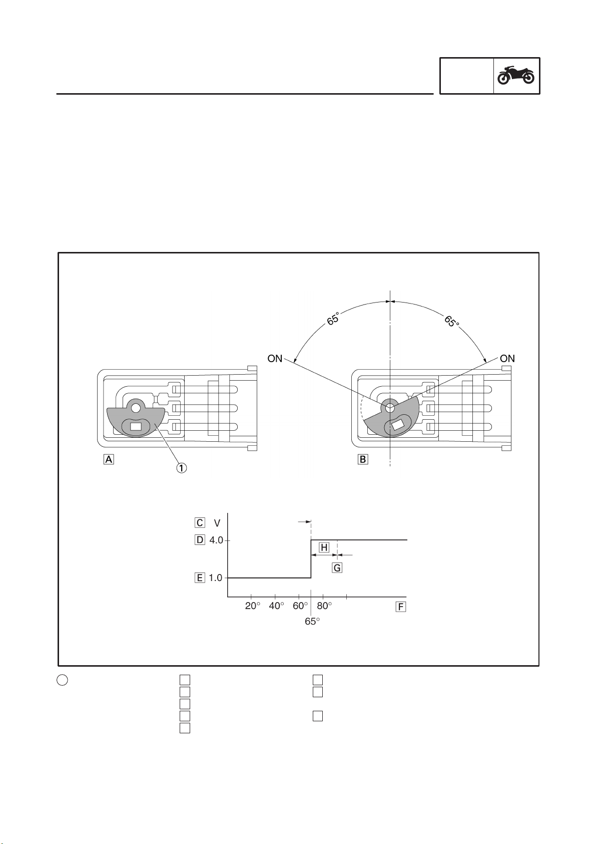
Lean angle cut-off switch
The lean angle cut-off switch stops the supply of fuel to the engine in case the motorcycle overturns.
When the motorcycle is in the normal state, the cut-off switch outputs a constant voltage of approximately 1.0 V (low level). When the motorcycle tilts, the float in the switch tilts in proportion to the tilt of
the motorcycle. However, the voltage output to the ECU remains unchanged at the low level.
When the tilt of the motorcycle exceeds 70 degrees (according to the tilt of the float), the signal from the
sensor increases to approximately 4.0 V (high level). When the ECU receives the high-level voltage, it
determines that the motorcycle has overturned, and stops the delivery of fuel to the engine by turning
OFF the fuel injection system relay that powers the fuel pump and the injectors. Once the cut-off switch
is tripped, the ECU maintains this state; therefore, even if the motorcycle has recovered its upright
position, this state will not be canceled unless the main switch is turned OFF, and then turned back ON.
INFO
1 Float
A Normal
B Tilts
C Output voltage
D High level
E Low level
F Cut-off switch tilt angle
G Fuel injection system
relay OFF
H Lag time
1-16
GEN
FEATURES
THREE-WAY CATALYTIC CONVERTER SYSTEM
System outline
This is a highly efficient exhaust gas cleaning system that effects air-fuel control through a joint effort by
the FI system, O
control of the air-fuel ratio in this manner, this system reduces the CO, HC, and NOx in the exhaust
gases.
The FI system controls the mixture to an optimal air-fuel ratio (basic air-fuel ratio) that matches the
operating condition of the engine in order to realize an ideal combustion.
Furthermore, an O
provided in the exhaust pipe for the purpose of maximizing the performance of the three-way catalytic
converter and to clean the exhaust gas at a high degree of efficiency. Based on this data, the ECU
applies more precise compensation to the basic air-fuel ratio, in order to maintain the mixture in the
vicinity of the stoichiometric air-fuel ratio of 14.7 : 1.
Through the joint effort of these control systems, the exhaust gas is cleaned in a highly efficient manner
without sacrificing engine performance.
Three-way catalytic converter system diagram
sensor, and the three-way catalytic converter system. By effecting comprehensive
2
sensor that detects the concentration of oxygen that remains in the exhaust gas is
2
INFO
1 Ignition coil
2 Injector
3 Intake air temperature
sensor
4 Intake solenoid
5 Throttle position
sensor
6 Intake air pressure
sensor
7 Crankshaft position
sensor
8 O
sensor
2
9 Coolant temperature
sensor
10 Cylinder identification
sensor
11 Spark plug
12 ECU
1-17
13 Igniter
14 Atmospheric pressure
sensor
15 Catalytic converter
GEN
FEATURES
Functions of components
Catalyst
Because the conditions in which NOx is generated are directly opposed to those of CO and HC, there is
a limit to the extent to which the concentration levels of these harmful elements can be reduced in the
combustion stage. Hence, the function of the catalyst is to clean the exhaust gas at a high degree of
efficiency by removing CO, HC, and NOx in the exhaust stage.
This model has adopted a monolith type metallic catalyst with a honeycomb construction, which
achieves a low exhaust resistance through the large surface area of the catalyst body (with a high level
of cleaning efficiency).
Catalytic substances consisting of precious metals such as platinum and rhodium are adhered to the
wall surface of these honeycomb cells, which are enclosed in the exhaust pipe. As the exhaust gas
comes in contact with these catalytic substances, the chemical reactions of oxidation and reduction
advance in order to clean the exhaust gas.
S The CO and HC oxidize with the oxidation function of platinum, and are converted into harmless
carbon dioxide (CO
) and water (H2O), resulting in cleaner exhaust gases.
2
INFO
CO + 1/2 O
HC + O
2
CO
2
CO2 + H2O
2
S The NOx is reduced by the reduction function of rhodium, which converts NOx into harmless nitro-
gen (N
) and oxygen (O2), resulting in cleaner exhaust gases.
2
NOx N
+ O
2
2
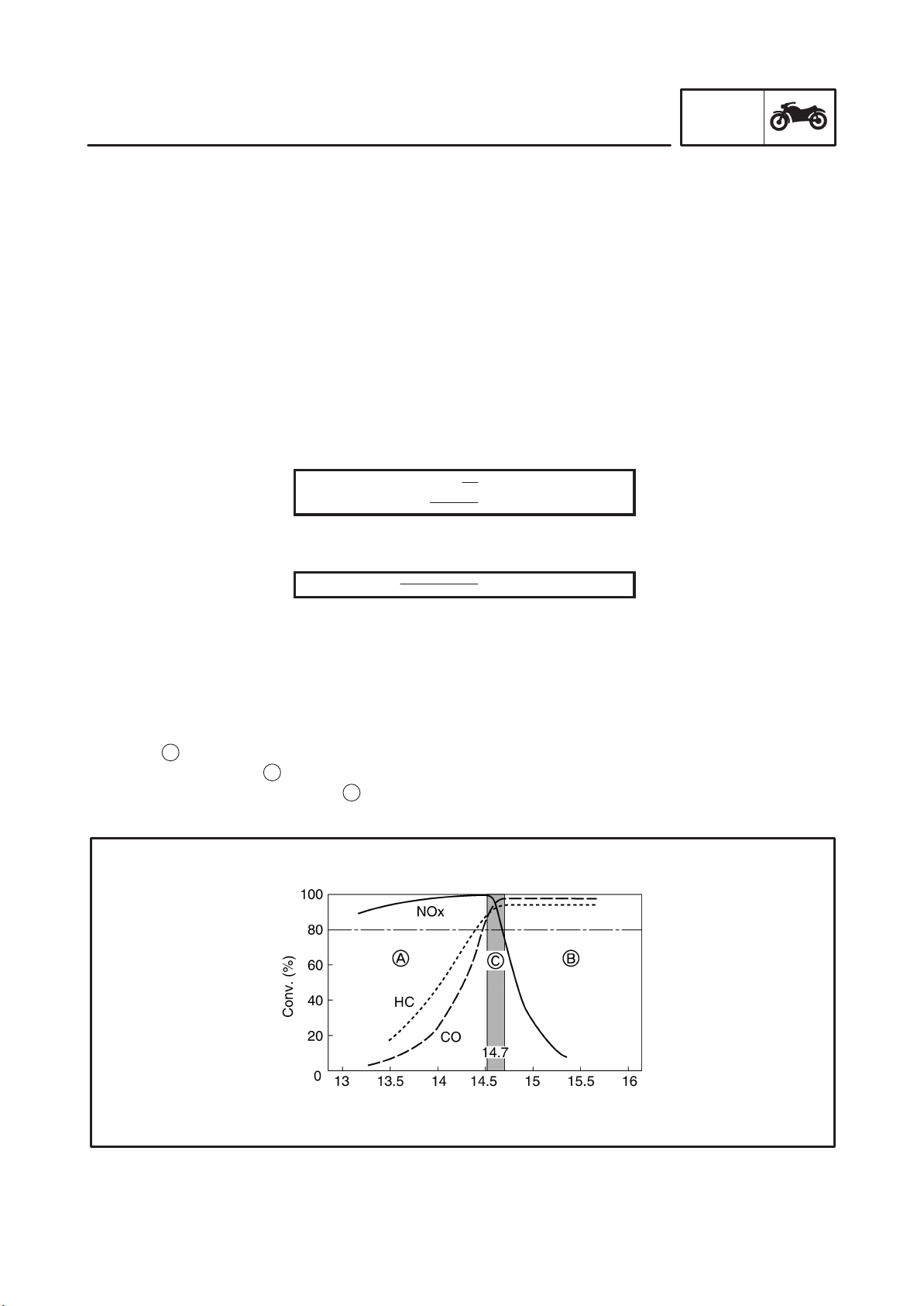
To clean the exhaust gases at a high rate of efficiency through the maximization of these catalytic capacities, it is necessary to maintain and control the mixture in the vicinity of the stoichiometric airfuel ratio
of (14.7 : 1) at all times. As a means of maintaining the stoichiometric ratio, this system has adopted an
O
feedback compensation method that uses an O2 sensor.
2
Large amounts of both CO and HC are generated when the mixture is rich (as indicated by insufficient
O
region A). Conversely, large amounts of NOx are generated when the mixture is lean (as indicated
2
by excessive O
within an extremely narrow range
region B). Under these conflicting characteristics, the system maintains the mixture
2
c
of stoichiometric ratio (14.7 : 1). As a result, the function of the
catalyst is maximized, making it possible to clean the exhaust gases at a high degree of efficiency.
1-18
GEN
FEATURES
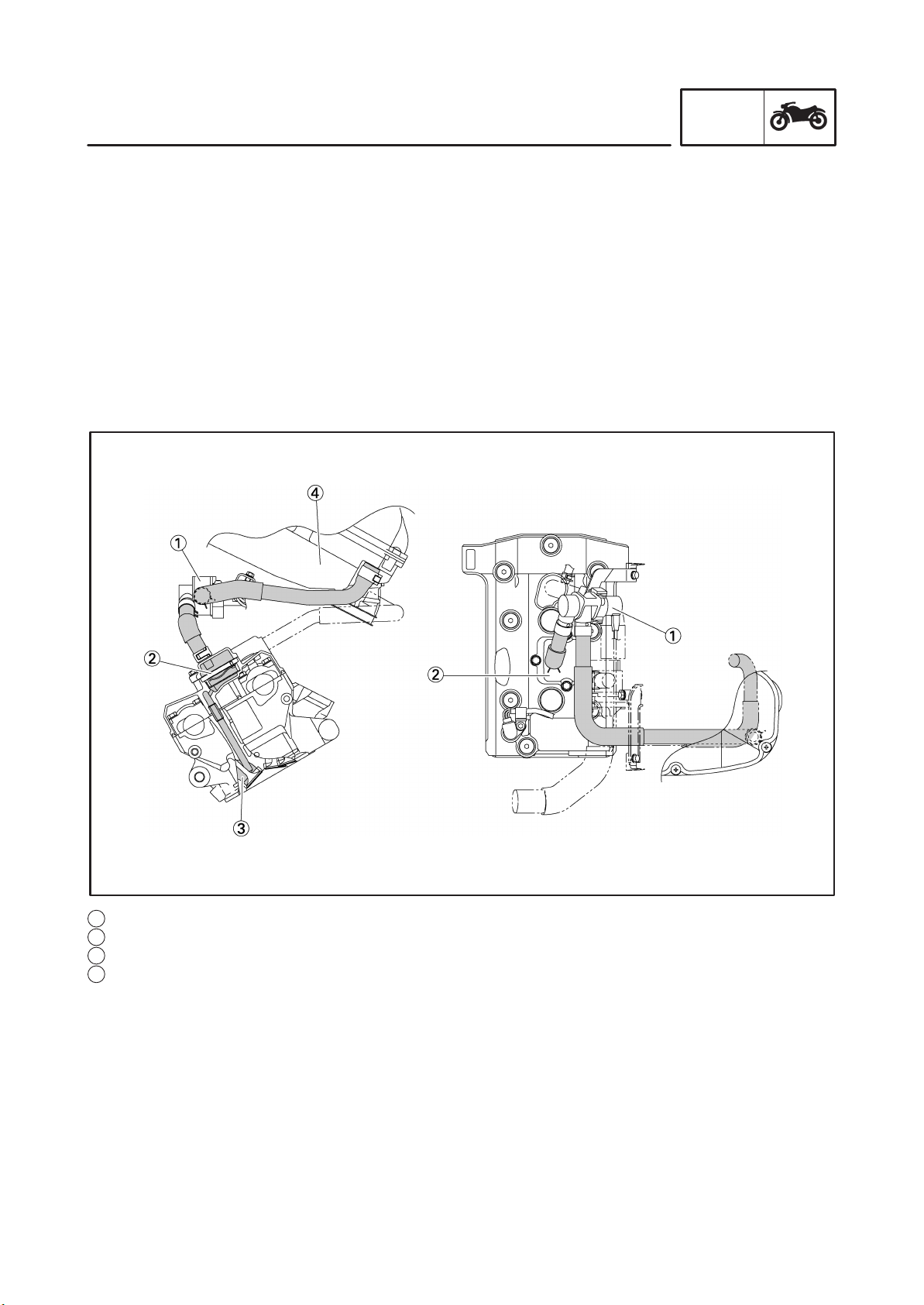
AIR INDUCTION SYSTEM
The air induction system (AI system) introduces fresh air into the exhaust port in order to burn the unburned gas (which is present in the exhaust gas) in the exhaust pipe. The burning of the unburned
gases in this manner enhances the efficiency of the catalyst and results in cleaner exhaust gases.
The AI system takes a portion of the air from the air cleaner, sends it to the reed valve via the air cut-off
valve, and introduces it directly into the exhaust port through the reed valve.
The air cut-off valve is controlled by the signals from the ECU in accordance with the combustion conditions. Ordinarily, the air cut-off valve opens to allow the air to flow during idle and closes to cut off the
flow when the motorcycle is being driven. However, if the coolant temperature is below the specified
value, the air cut-off valve remains open and allows the air to flow into the exhaust pipe until the temperature becomes higher than the specified value.
The reed valve is provided on the cylinder head cover above the cylinders, and sends air to the exhaust
pipe through the inside of the cylinder head.
INFO
1 Air cut-off valve
2 Reed valve
3 Exhaust port
4 Air filter case
1-19
 Loading...