

Page 1

2005
TDM900A(T)
5PS1-AE4
SUPPLEMENTARY
SERVICE MANUAL
Page 2

Page 3

FOREWORD
This Supplementary Service Manual has been prepared to introduce new service and data for the
TDM900A(T) 2005. For complete service information procedures it is necessary to use this Supplementary Service Manual together with the following manual.
TDM900(N) 2001 SERVICE MANUAL: 5PS1-AE1
TDM900(R) 2003 SUPPLEMENTARY SERVICE MANUAL: 5PS1-AE2
TDM900(S) 2004 SUPPLEMENTARY SERVICE MANUAL: 5PS1-AE3
TDM900A(T) 2005
SUPPLEMENTARY
SERVICE MANUAL
©2004 by Yamaha Motor Co., Ltd.
First Edition, December 2004
All rights reserved.
Any reproduction or unauthorized use
without the written permission of
Yamaha Motor Co., Ltd.
is expressly prohibited.
Page 4
EAS00002
NOTICE
This manual was produced by the Yamaha Motor Company, Ltd. primarily for use by Yamaha dealers and their qualified mechanics. It is not possible to include all the knowledge of a mechanic in one
manual. Therefore, anyone who uses this book to perform maintenance and repairs on Yamaha
vehicles should have a basic understanding of mechanics and the techniques to repair these types
of vehicles. Repair and maintenance work attempted by anyone without this knowledge is likely to
render the vehicle unsafe and unfit for use.
Yamaha Motor Company, Ltd. is continually striving to improve all its models. Modifications and significant changes in specifications or procedures will be forwarded to all authorized Yamaha dealers
and will appear in future editions of this manual where applicable.
NOTE:
Designs and specifications are subject to change without notice.
EAS00004
IMPORTANT INFORMATION
Particularly important information is distinguished in this manual by the following.
WARNING
CAUTION:
NOTE:
The Safety Alert Symbol means ATTENTION! BECOME ALERT! YOUR
SAFETY IS INVOLVED!
Failure to follow WARNING instructions could result in severe injury or death
to the motorcycle operator, a bystander or a person checking or repairing the
motorcycle.
A CAUTION indicates special precautions that must be taken to avoid damage to the motorcycle.
A NOTE provides key information to make procedures easier or clearer.
Page 5
EAS00007
HOW TO USE THIS MANUAL
This manual is intended as a handy, easy-to-read reference book for the mechanic. Comprehensive
explanations of all installation, removal, disassembly, assembly, repair and check procedures are
laid out with the individual steps in sequential order.
The manual is divided into chapters. An abbreviation and symbol in the upper right corner of
each page indicate the current chapter.
Refer to “SYMBOLS”.
Each chapter is divided into sections. The current section title is shown at the top of each page,
except in Chapter 3 (“PERIODIC CHECKS AND ADJUSTMENTS”), where the sub-section title(s)
appears.
Sub-section titles appear in smaller print than the section title.
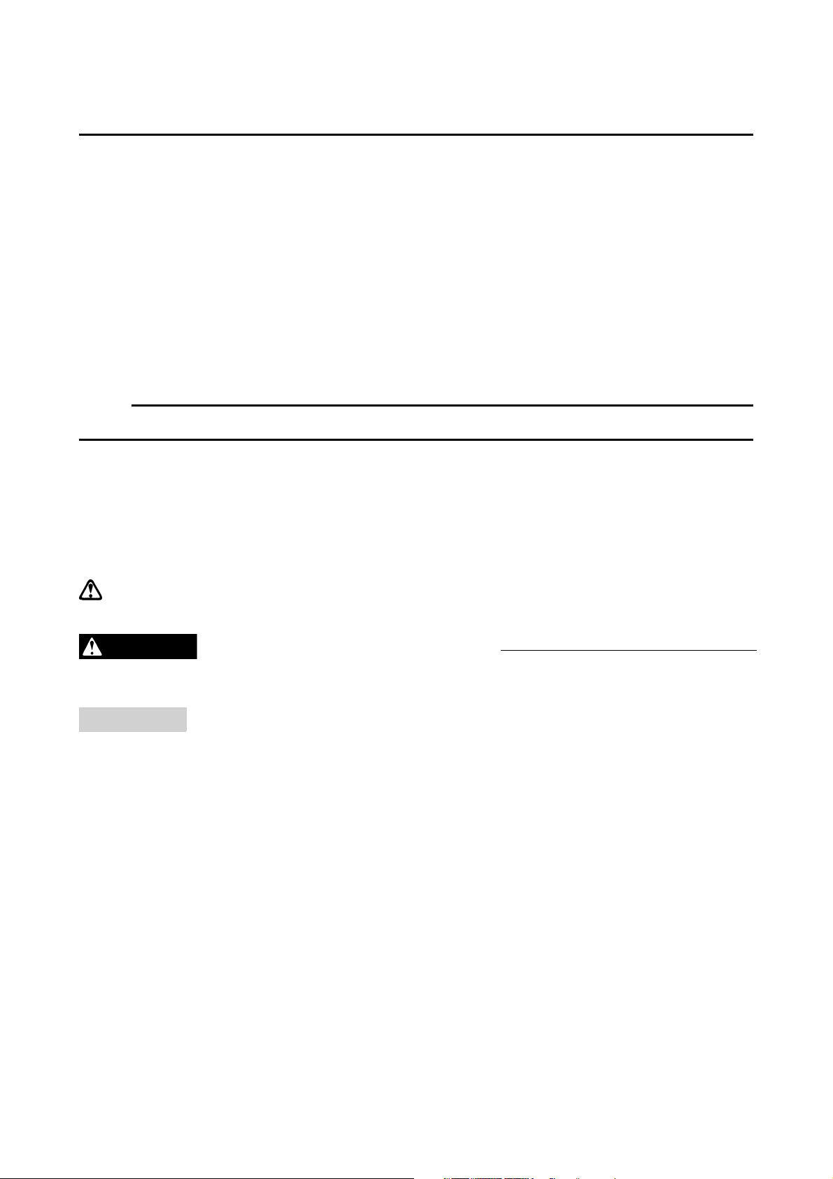
To help identify parts and clarify procedure steps, there are exploded diagrams at the start of
each removal and disassembly section.
Numbers are given in the order of the jobs in the exploded diagram. A circled number indicates a
disassembly step.
Symbols indicate parts to be lubricated or replaced.
Refer to “SYMBOLS”.
A job instruction chart accompanies the exploded diagram, providing the order of jobs, names of
parts, notes in jobs, etc.
Jobs requiring more information (such as special tools and technical data) are described
sequentially.
Page 6

EAS00008
SYMBOLS
The following symbols are not relevant to every
vehicle.
Symbols to indicate the subject of each
chapter.
General information
Specifications
Periodic checks and adjustments
Chassis
Engine
Cooling system
Fuel injection system
Electrical system
Troubleshooting
Symbols to indicate the following.
Serviceable with engine mounted
Filling fluid
Lubricant
Special tool
Tightening torque
Wear limit, clearance
Engine speed
Electrical data
Symbols to in the exploded diagrams
indicate the types of lubricants and lubrication
points.
Engine oil
Gear oil
Molybdenum-disulfide oil
Wheel-bearing grease
Lithium-soap- based grease
Molybdenum-disulfide grease
Symbols to in the exploded diagrams
indicate the following.
Apply locking agent (LOCTITE
®
)
Replace the part
Page 7

CONTENTS
GENERAL INFORMATION
FEATURES . . . . . . . . . . . . . . . . . . . . . . . . . . . . . . . . . . . . . . . . . . . . . 1
INSTRUMENT PANEL. . . . . . . . . . . . . . . . . . . . . . . . . . . . . . . . . . 1
SPECIAL TOOLS . . . . . . . . . . . . . . . . . . . . . . . . . . . . . . . . . . . . . . . . 4
SPECIFICATIONS
GENERAL SPECIFICATIONS . . . . . . . . . . . . . . . . . . . . . . . . . . . . . . 5
ENGINE SPECIFICATIONS . . . . . . . . . . . . . . . . . . . . . . . . . . . . . . . . 5
CHASSIS SPECIFICATIONS . . . . . . . . . . . . . . . . . . . . . . . . . . . . . . . 5
ELECTRICAL SPECIFICATIONS. . . . . . . . . . . . . . . . . . . . . . . . . . . . 6
TIGHTENING TORQUES . . . . . . . . . . . . . . . . . . . . . . . . . . . . . . . . . . 7
CHASSIS TIGHTENING TORQUES . . . . . . . . . . . . . . . . . . . . . . . 7
CABLE ROUTING. . . . . . . . . . . . . . . . . . . . . . . . . . . . . . . . . . . . . . . . 8
SWINGARM AND DRIVE CHAIN . . . . . . . . . . . . . . . . . . . . . . . . . . . . 28
CHECKING THE DRIVE CHAIN . . . . . . . . . . . . . . . . . . . . . . . . . . 28
ANTI-LOCK BRAKE SYSTEM (ABS) . . . . . . . . . . . . . . . . . . . . . . . . 30
ABS OUTLINE . . . . . . . . . . . . . . . . . . . . . . . . . . . . . . . . . . . . . . . . 30
ABS . . . . . . . . . . . . . . . . . . . . . . . . . . . . . . . . . . . . . . . . . . . . . . . . 31
ABS COMPONENTS . . . . . . . . . . . . . . . . . . . . . . . . . . . . . . . . . . . 49
FRONT WHEEL SENSOR AND SENSOR ROTOR . . . . . . . . . . . 50
REAR WHEEL SENSOR AND SENSOR ROTOR . . . . . . . . . . . . 54
HYDRAULIC UNIT. . . . . . . . . . . . . . . . . . . . . . . . . . . . . . . . . . . . . 57
HYDRAULIC ABS . . . . . . . . . . . . . . . . . . . . . . . . . . . . . . . . . . . . . 64
CHECKING THE RESERVOIR TANK FLUID LEVEL . . . . . . . . . . 73
TRIAL RUN . . . . . . . . . . . . . . . . . . . . . . . . . . . . . . . . . . . . . . . . . . 73
ELECTRICAL
ELECTRICAL COMPONENTS . . . . . . . . . . . . . . . . . . . . . . . . . . . . . . 74
CHECKING THE SWITCHES . . . . . . . . . . . . . . . . . . . . . . . . . . . . . . . 76
ELECTRIC STARTING SYSTEM . . . . . . . . . . . . . . . . . . . . . . . . . . . . 77
CIRCUIT DIAGRAM. . . . . . . . . . . . . . . . . . . . . . . . . . . . . . . . . . . . 77
STARTING CIRCUIT CUT-OFF SYSTEM OPERATION . . . . . . . 78
TROUBLESHOOTING. . . . . . . . . . . . . . . . . . . . . . . . . . . . . . . . . . 79
SIGNALING SYSTEM. . . . . . . . . . . . . . . . . . . . . . . . . . . . . . . . . . . . . 83
CIRCUIT DIAGRAM. . . . . . . . . . . . . . . . . . . . . . . . . . . . . . . . . . . . 83
TROUBLESHOOTING. . . . . . . . . . . . . . . . . . . . . . . . . . . . . . . . . . 85
CHECKING THE SIGNAL SYSTEM . . . . . . . . . . . . . . . . . . . . . . . 86
Page 8

ANTI-LOCK BRAKE SYSTEM (ABS) . . . . . . . . . . . . . . . . . . . . . . . . 94
CIRCUIT DIAGRAM. . . . . . . . . . . . . . . . . . . . . . . . . . . . . . . . . . . . 94
ABS COMPONENTS . . . . . . . . . . . . . . . . . . . . . . . . . . . . . . . . . . . 96
ABS CONNECTOR LOCATION CHART. . . . . . . . . . . . . . . . . . . . 97
ECU (ABS) AND FAIL-SAFE RELAY . . . . . . . . . . . . . . . . . . . . . . 98
TROUBLESHOOTING. . . . . . . . . . . . . . . . . . . . . . . . . . . . . . . . . . 103
CHECKING THE ANTI-LOCK BRAKE SYSTEM. . . . . . . . . . . . . . 104
TROUBLESHOOTING BY THE SELF DIAGNOSIS . . . . . . . . . . . 107
MALFUNCTION CHECK BY THE ABS SELF DIAGNOSIS
(PAST MALFUNCTION) . . . . . . . . . . . . . . . . . . . . . . . . . . . . . . . . 107
MALFUNCTION CHECK BY THE ABS SELF DIAGNOSIS
(PRESENT MALFUNCTION). . . . . . . . . . . . . . . . . . . . . . . . . . . . . 108
DELETING THE MALFUNCTION CODE . . . . . . . . . . . . . . . . . . . 120
TROUBLESHOOTING
ANTI-LOCK BRAKE SYSTEM (ABS) . . . . . . . . . . . . . . . . . . . . . . . . 122
ABS TROUBLESHOOTING OUTLINE . . . . . . . . . . . . . . . . . . . . . 122
BASIC INSTRUCTION FOR TROUBLESHOOTING. . . . . . . . . . . 123
BASIC PROCESS FOR TROUBLESHOOTING . . . . . . . . . . . . . . 124
TROUBLESHOOTING AT THE ABS WARNING LIGHT . . . . . . . . . . 125
ONLY THE ABS WARNING LIGHT DOES NOT COME ON. . . . . 125
ALL INDICATORS DO NOT COME ON. . . . . . . . . . . . . . . . . . . . . 125
ABS WARNING LIGHT CONTINUES TO FLASHES. . . . . . . . . . . 125
ABS WARNING LIGHT FLASHES EVERY 0.5 SECONDS. . . . . . 125
ABS WARNING LIGHT CONTINUES TO COME ON. . . . . . . . . . 125
TDM900A(T) 2005 WIRING DIAGRAM
Page 9
FEATURES
INSTRUMENT PANEL
FEATURES
GENERAL INFORMATION
GEN
INFO
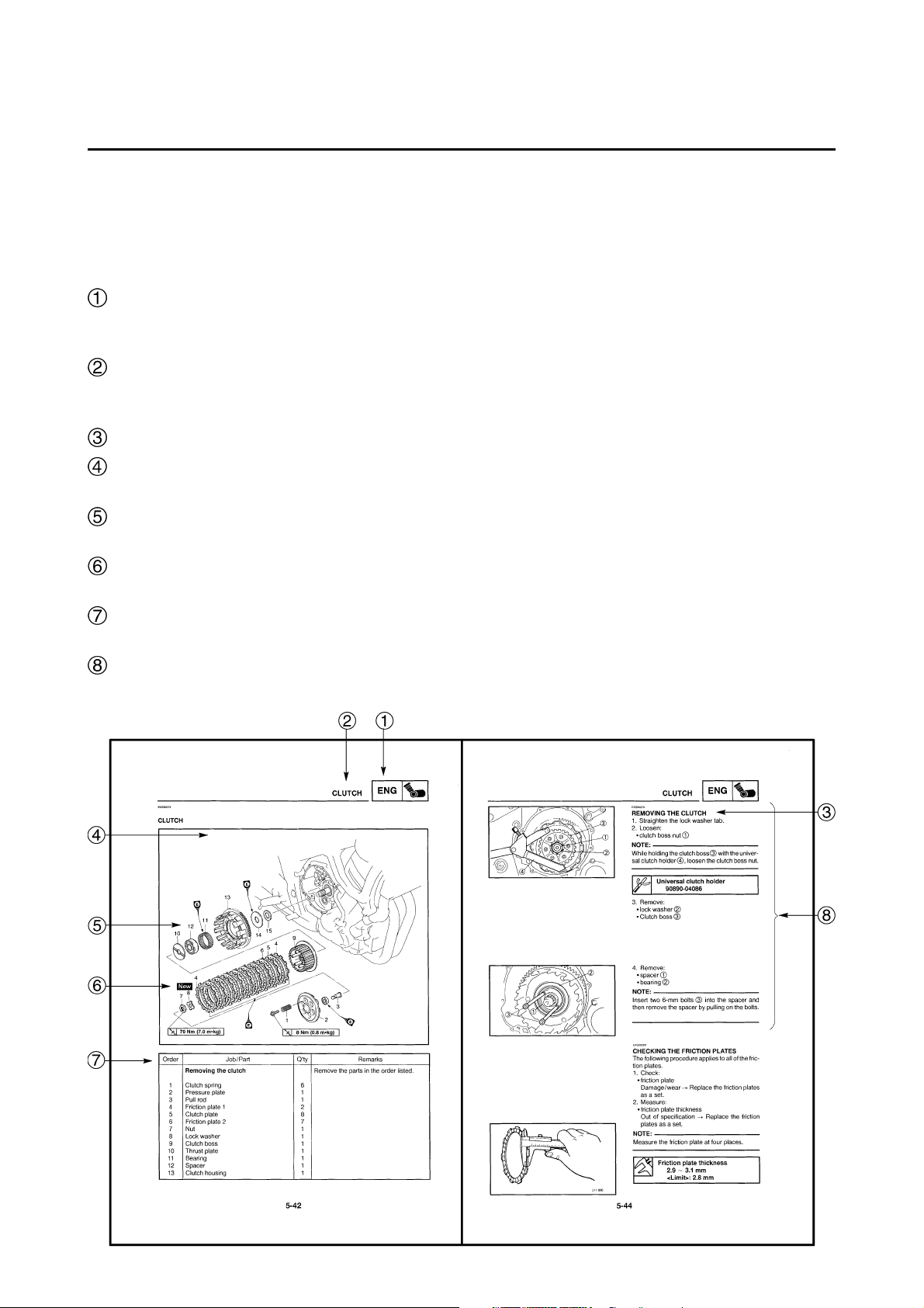
Clock
TRIP/ODO meter
SELECT button
RESET button
Engine trouble warning light
Function indication
The indications of the self-diagnosis function can be checked and inspection operations can be performed through the use of the multi-function meter on the instrument panel.
Based on the signals received from the sensors, the ECU inputs the signals into the multi-function
meter. Then, the conditions of the sensors appear on the clock and trip/odometer display of the
multi-function meter.
NORMAL MODE
CO ADJUSTMENT/DIAGNOSTIC
MONITORING SELECTION MODE
Speed meter
Fuel meter
(The symbol “ ” blinks when the gasoline is
almost empty)
Trip / odometer display
Clock display
Temporary selection display for CO/ DIAG.
CO:
DIAG:
1
Page 10
FEATURES
GEN
INFO
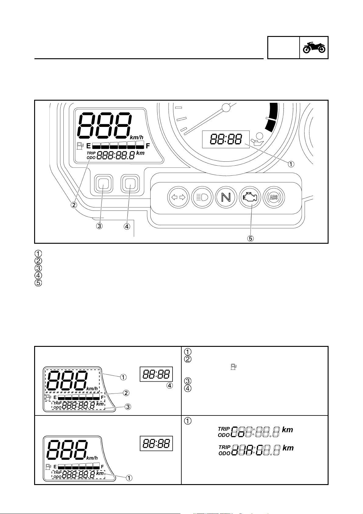
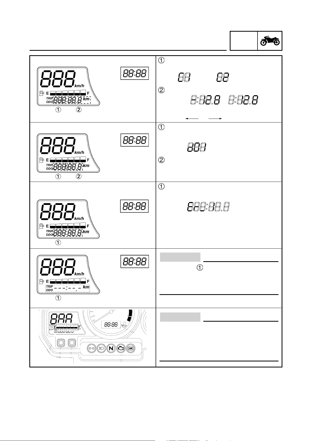
CO ADJUSTMENT MODE
DIAGNOSTIC MONITORING MODE
WHEN THE COMMUNICATION ERROR
OCCURRED BETWEEN ECU AND METER:
Cylinder identification
For #1 For #2
CO data
Example:
lean rich
–128 0 128
Diagnostic monitoring code
Example: code “01”
Monitoring data
Error code
Example: When the error code is “Er-1”
For details of error codes, refer to
“FAIL-SAFE ACTION TABLE” in chapter 7.
(Manual No.: 5PS1-AE1)
CAUTION:
If the display shown in the illustration to
the left appears, the multi-function display
is malfunctioning. Replace the meter
assembly.
CAUTION:
If the fuel meter does not display the fuel
level, but repeatedly flashes as shown in
the illustration, the fuel level monitoring
system is malfunctioning. Check the fuel
sender and the electrical circuit.
2
Page 11
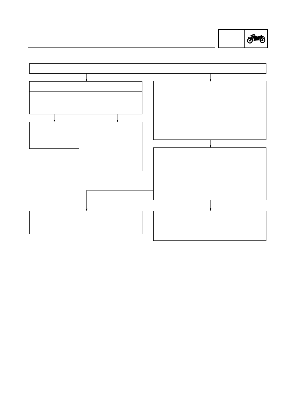
CO adjustment and diagnostic monitoring mode
Mode Selection
FEATURES
GEN
INFO
Normal mode
Turn “ON” the main switch
• The self-diagnostic function starts a system
check
System normal Malfunction detec-
Normal meter display
CO adjustment mode
Refer to “CO adjustment” in chapter 3.
(Manual No.: 5PS1-AE1)
tion fault number
appears on the
clock LCD.
The engine trouble warning light
illuminates.
CO/DIAG mode
1. While keeping both the SELECT and
RESET buttons pressed, turn “ON” the
main switch. Keep the buttons pressed for
8 seconds or more.
• All the segments are “OFF” expect the clock
and the trip LCD.
• “DIAG” appears on the clock LCD.
Switching between CO adjustment mode and
DIAG mode
1. Press the SELECT button in order to
switch the display to “CO” or “DIAG”.
2. Simultaneously press the SELECT and
RESET buttons for 2 seconds or more to
select an item.
Diagnosis monitoring mode
Refer to “TROUBLESHOOTING” in chapter
7.
(Manual No.: 5PS1-AE1)
(The engine cannot be started in this mode)
3
Page 12
GEN
SPECIAL TOOLS
EB104000
SPECIAL TOOLS
The following special tools are necessary for complete and accurate tune-up and assembly.
Use only the appropriate special tools as this will help prevent damage caused by the use of inappropriate tools or improvised techniques.
When placing an order, refer to the list provided below to avoid any mistakes.
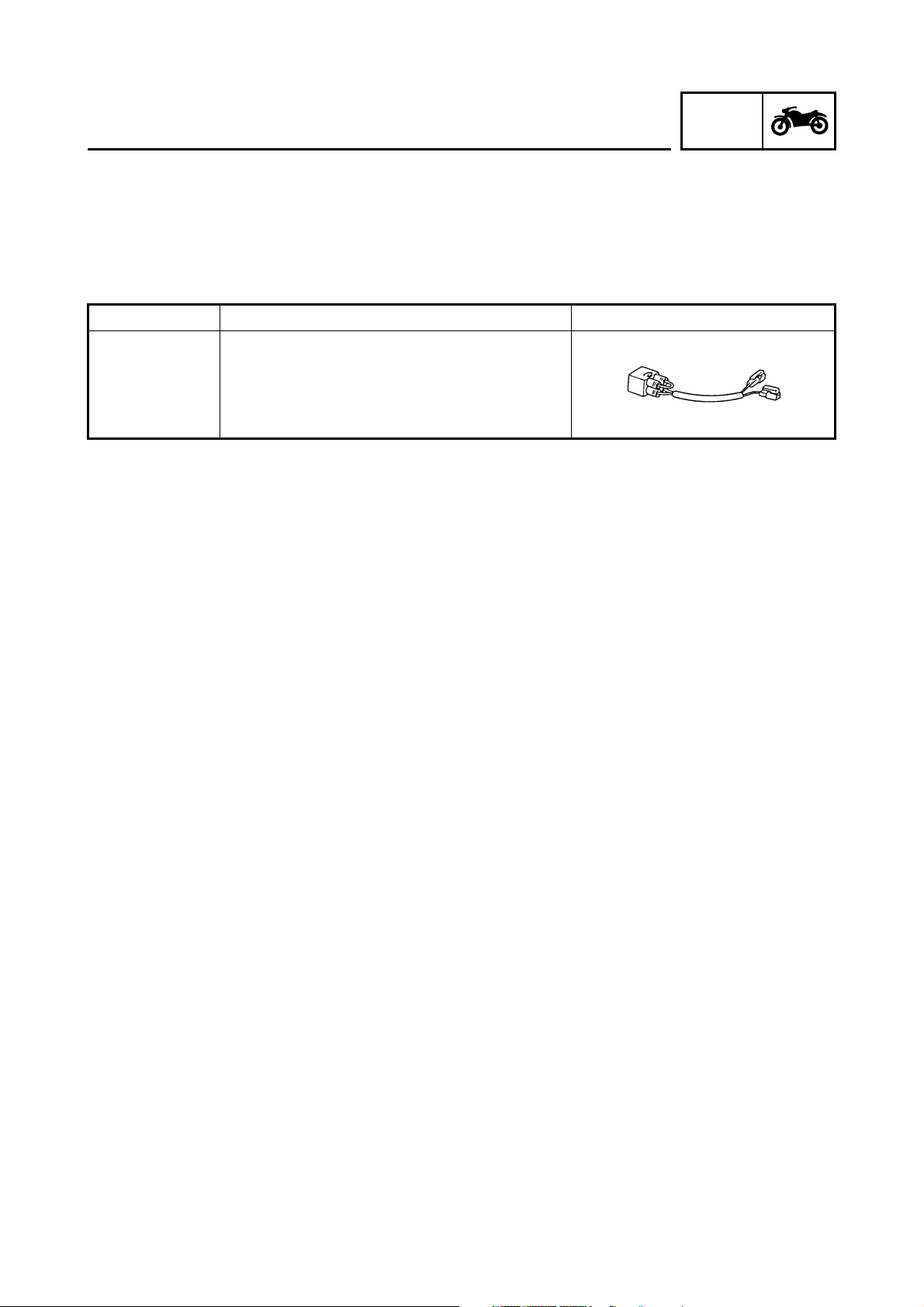
Tool No. Tool name/Function Illustration
Test coupler adaptor
90890-03149
This tool is used to check the ABS diagnosis.
INFO
4
Page 13

GENERAL SPECIFICATIONS/
ENGINE SPECIFICATIONS/CHASSIS SPECIFICATIONS
SPEC
SPECIFICATIONS
GENERAL SPECIFICATIONS
Item Standard Limit
Model code 2B01 (EUR) •
Weight
Wet (with oil and a full fuel tank) 224 kg (494 lb) •
Dry (without oil and fuel) 193 kg (426 lb) •
Maximum load (total of cargo, rider,
200 kg (441 lb) •
passenger, and accessories)
ENGINE SPECIFICATIONS
Item Standard Limit
Throttle bodies
Model (manufacturer) × quantity 38EIS (MIKUNI) × 2•
ID mark 5PS1 11 •
• •
• •
• •
• •
• •
• •
CHASSIS SPECIFICATIONS
Item Standard Limit
Front tire
Tire type Tubeless •
Size 120 / 70ZR 18M / C (59W) •
Model (manufacturer) D220FSTJ (DUNLOP) •
Tire pressure (cold)
0 ~ 90 kg 225 kPa (2.25 kgf/cm
90 ~ 200 kg 225 kPa (2.25 kgf/cm
High-speed riding 225 kPa (2.25 kgf/cm
Min. tire tread depth •
• • 1.6 mm
Rear tire
Tire type Tubeless •
Size 160 / 60ZR 17M / C (69W) •
Model (manufacturer) D220STJ (DUNLOP) •
Tire pressure (cold)
0 ~ 90 kg 250 kpa (2.5 kgf/cm
90 ~ 200 kg 290 kPa (2.9 kgf/cm
High-speed riding 250 kPa (2.5 kgf/cm
Min. tire tread depth •
• • 1.6 mm
Drive chain:
Type (manufacturer) DID525HV KAI (DAIDO) •
Link quantity 118 •
Drive chain slack 50 ~ 60 mm •
Maximum 15-link section •
• • 239.3 mm
2
, 2.25 bar, 32 psi) • • •
2
, 2.25 bar, 32 psi) • • •
2
, 2.25 bar, 32 psi) • • •
2
, 2.5 bar, 35.6 psi) • • •
2
, 2.9 bar, 41.3 psi) • • •
2
, 2.5 bar, 35.6 psi) • • •
• •
• •
• •
(0.06 in)
• •
• •
• •
(0.06 in)
• •
• •
• •
(9.42 in)
5
Page 14
ELECTRICAL SPECIFICATIONS
SPEC
ELECTRICAL SPECIFICATIONS
Item Standard Limit
Ignition system
Ignition system type Transistorized coil ignition (digital) •
Ignition timing 10° BTDC at 1,150 r/min •
Advancer type Electric •
Pickup coil resistance/color 192 ~ 288 Ω/L/Y-G/W •
Transistorized coil ignition unit model
TBDF15 (DENSO) •
(manufacturer)
Indicator light
(voltage/ wattage × quantity)
Turn signal indicator light 14 V 1.2 W × 1•
ABS warning light 14 V 1.4 W × 1•
Starter relay
Model (manufacturer) MS5F-631 (JIDECO) •
Amperage 180 A •
Coil resistance 4.18 ~ 4.62 Ω •
Front wheel sensor
Model (manufacturer) OELABW (SUMITOMO) •
Resistance 1.2 ~ 1.6 kΩ at 20°C •
Rear wheel sensor
Model (manufacturer) OELABX (SUMITOMO) •
Resistance 1.2 ~ 1.6 kΩ at 20°C •
Fail-safe relay
Model (manufacturer) G8R-40Y (OMRON) •
Fuses (amperage × quantity)
Main fuse 40 A × 1•
Fuel injection system fuse 10 A × 1•
Headlight fuse 20 A × 1•
Signaling system fuse 10 A × 1•
Ignition fuse 10 A × 1•
Radiator fan motor fuse 20 A × 1•
Hazard light fuse 10 A × 1•
Backup fuse 10 A × 1•
ABS fuse 10 A × 1•
ABS motor fuse 30 A × 1•
Reserve fuse 20 A × 1•
10 A × 1•
• •
• •
• •
• •
• •
• •
• •
• •
• •
• •
• •
• •
• •
• •
• •
• •
• •
• •
• •
• •
• •
• •
• •
• •
• •
• •
• •
6
Page 15
TIGHTENING TORQUES
CHASSIS TIGHTENING TORQUES
TIGHTENING TORQUES
SPEC
Part to be tightened
Lower bracket pinch bolt M8 23 2.3 16.6
Upper bracket and wire guide M6 7 0.7 5.1
Throttle cable adjusting nut M6 5 0.5 3.6
Engine mounting:
Rear upper mounting bolt and nut M10 45 4.5 32.5
Rear lower mounting bolt and nut M10 45 4.5 32.5
Pinch bolt M8 26 2.6 18.8
Frame and rear frame M10 41 4.1 29.7
Sidestand and sidestand bracket M8 23 2.3 16.6
Sidestand bracket and frame M8 26 2.6 18.8
Rear footrest and footrest bracket M6 9 0.9 6.5
Front wheel sensor and sensor housing M8 30 3.0 22
Rear wheel sensor and sensor housing M8 30 3.0 22
Hydraulic unit and hydraulic unit bracket M8 16 1.6 12
Hydraulic unit bracket and frame M8 16 1.6 12
Hydraulic unit and brake hose M10 30 3.0 22
Front brake hose holder and front brake hose M6 10 1.0 7.2
Rear brake hose holder and rear brake hose M6 7 0.7 5.0
Frame and connector plate M5 7 0.7 5.0
Frame and brake hose holder M6 10 1.0 7.2
Thread
size
Tightening
torque
Nm m•kg ft•lb
Remarks
7
Page 16
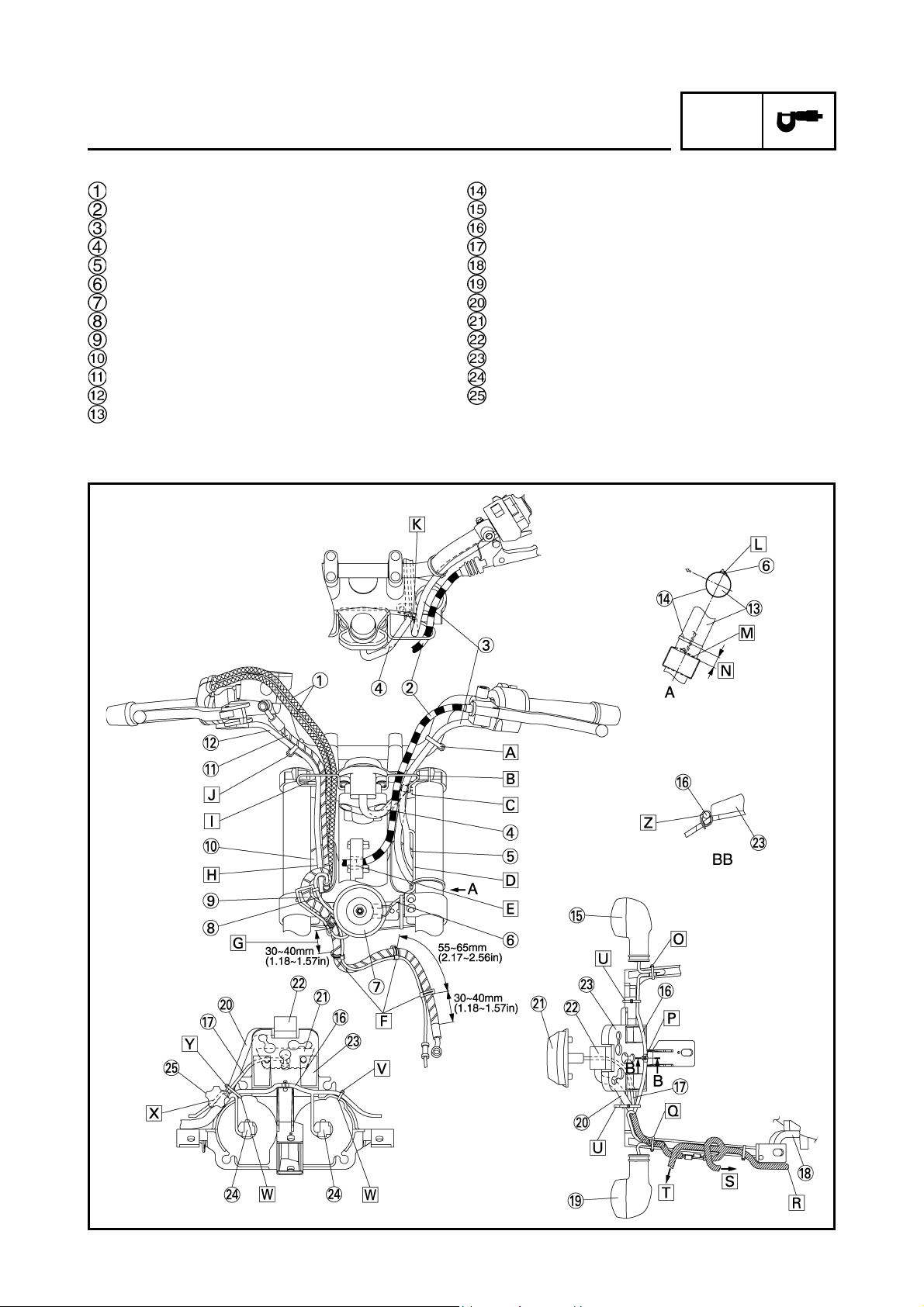
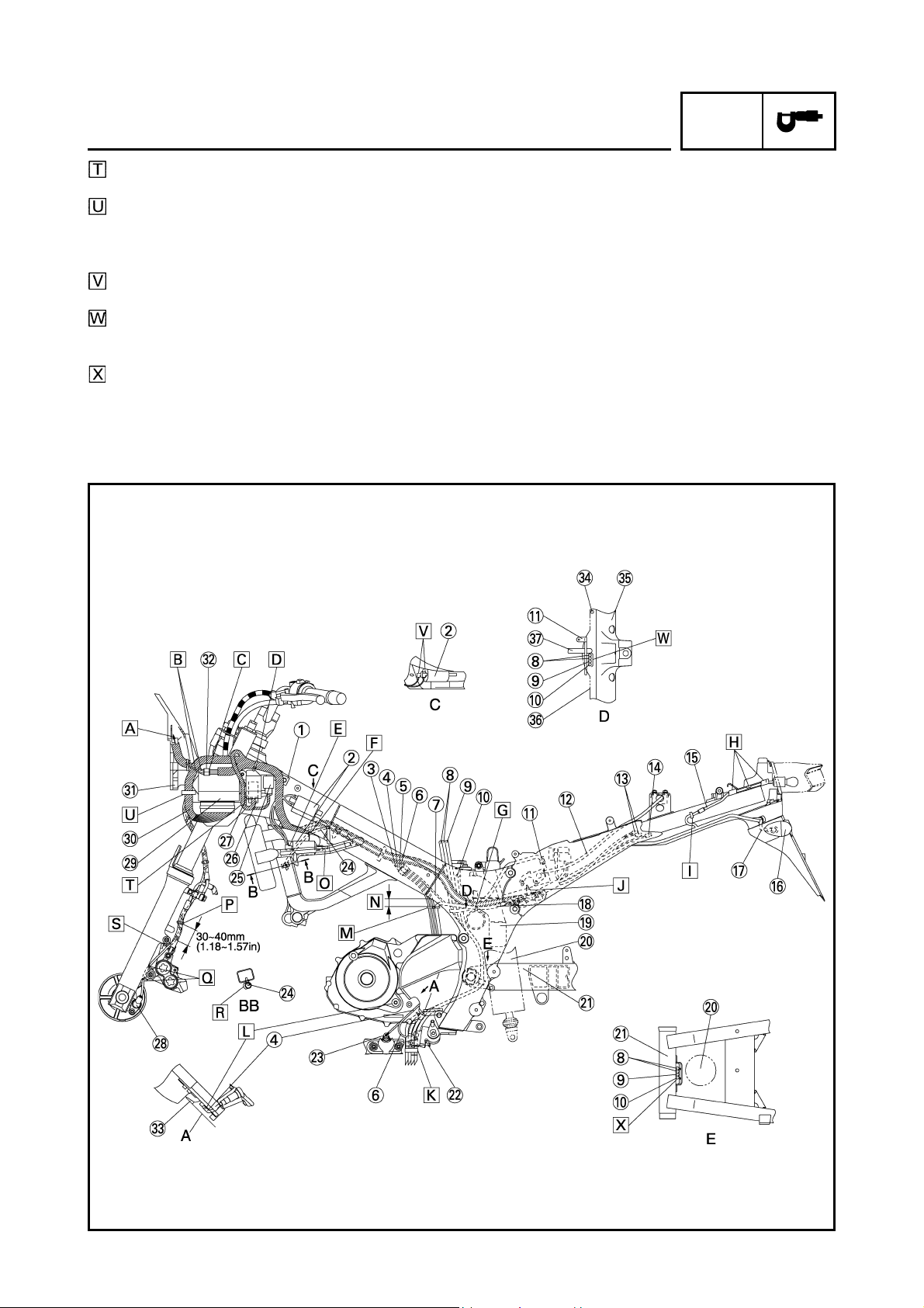
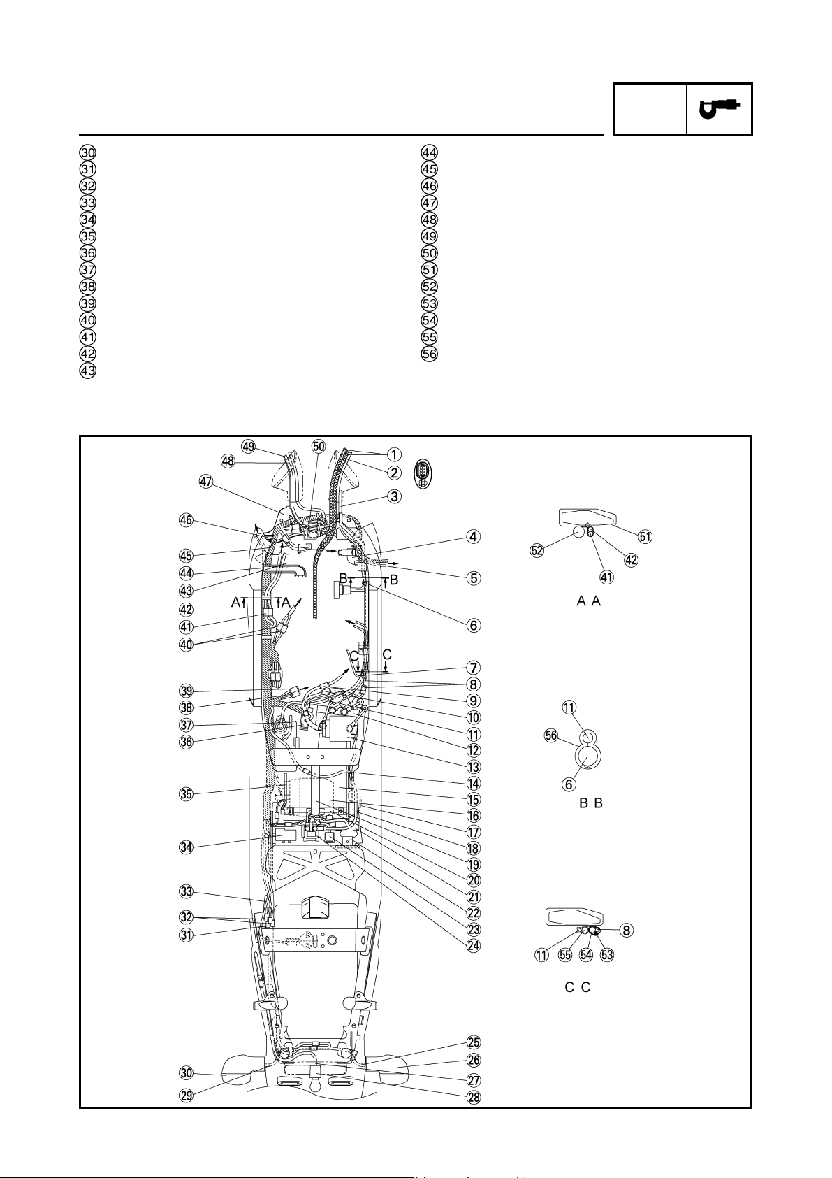
CABLE ROUTING
Throttle cables
Clutch cable
Left handlebar switch lead
Main switch lead and immobilizer lead
Cover 7
Horn lead
Horn
Front wheel sensor lead
Front brake hose (OUT)
Cover 8
Front brake hose (IN)
Right handlebar switch lead
Front fork
CABLE ROUTING
Clamp
Front turn signal light (right)
Headlight sub-wire harness
Indicator light lead
Stay 3
Front turn signal light (left)
Meter lead
Indicator light
Meter
Stay 1
Headlight coupler
Headlight adjusting knob
SPEC
8
Page 17
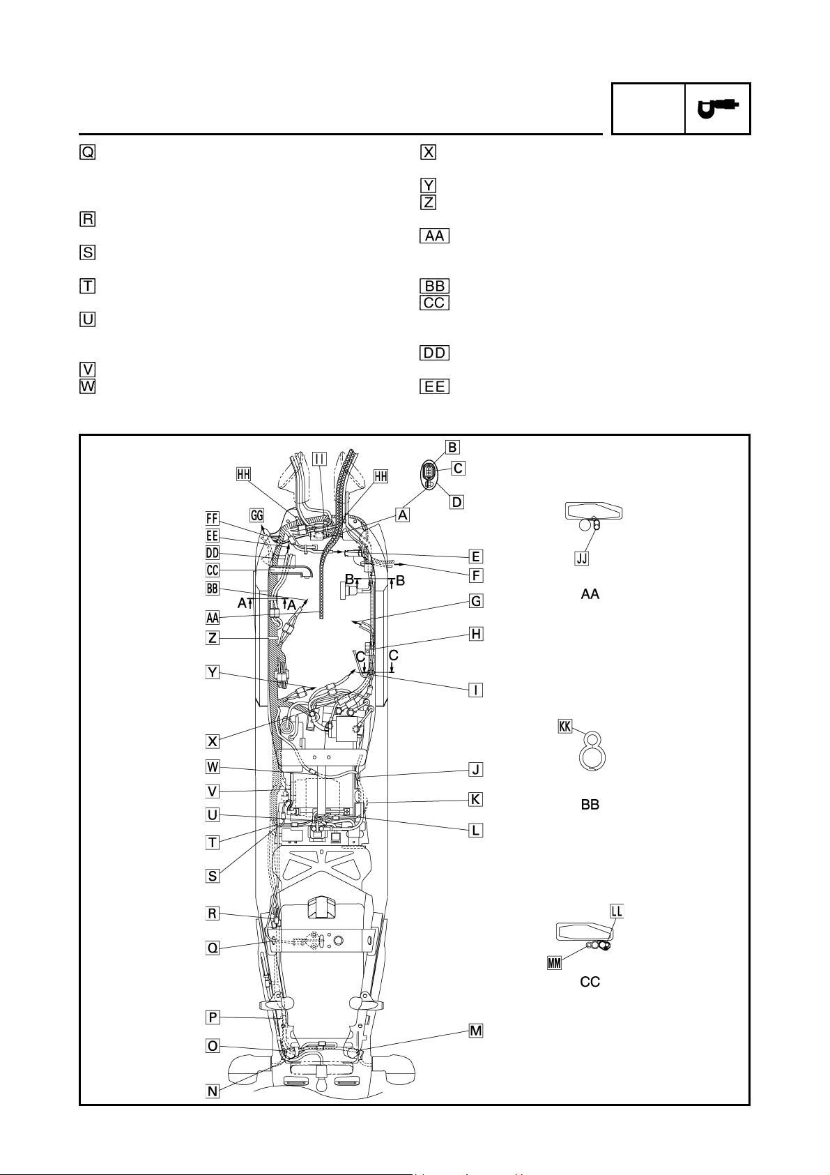
CABLE ROUTING
SPEC
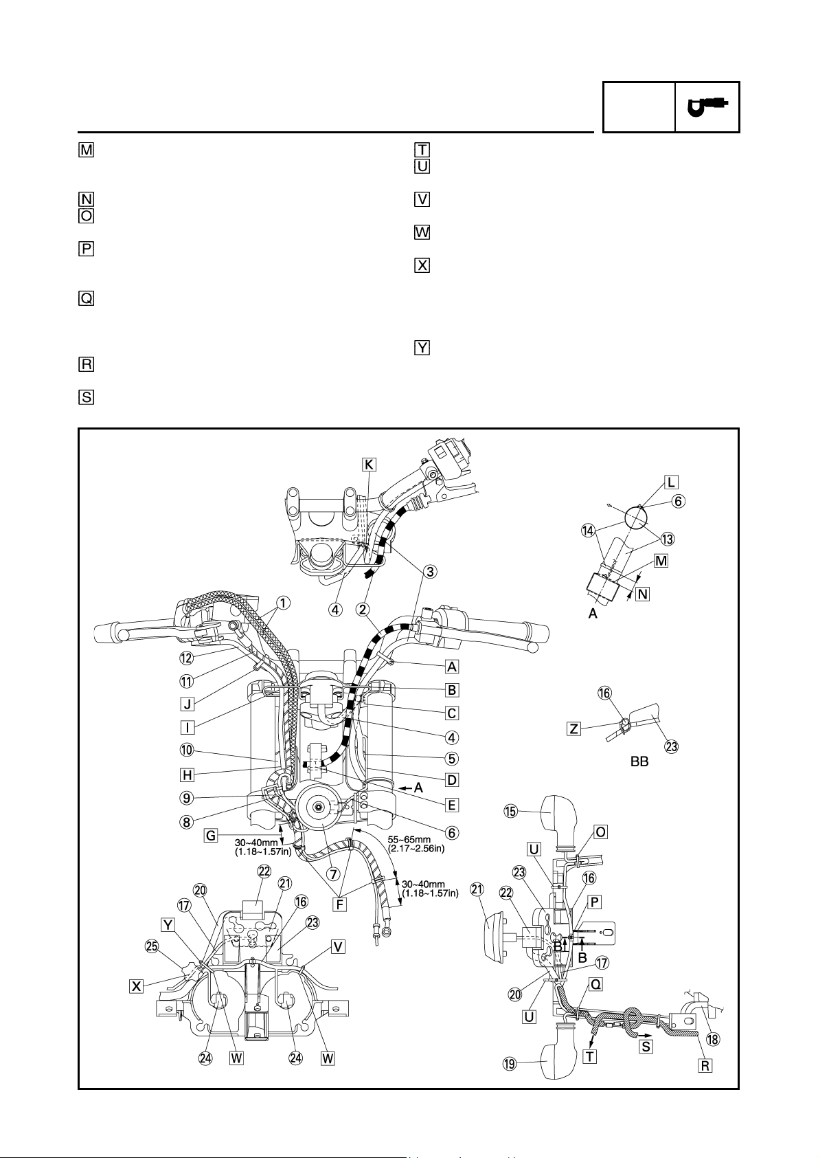
Fasten the left handlebar switch lead to the handlebar with a band.
Through the left handlebar switch lead and clutch
cable to the wire guide on the upper bracket.
Fasten the main switch lead and immobilizer lead
to the wire guide with a clamp. There should be no
slack between main switch and wire guide. Cut the
clamp tip leaving 3 ~ 8 mm (0.12 ~ 0.31 in).
Route the main switch lead through the cover 7 so
that it route beneath the left handlebar switch lead.
Route the clutch cable through the hole in front of
the head pipe on the frame.
Route the front wheel sensor lead along the brake
hose and clamp it at the position shown the drawing.
It should be 30 ~ 40 mm (1.18 ~ 1.57 in) from the
lower end of the grommet of the brake hose.
Route the right handlebar switch lead, front brake
hose (IN, OUT), front wheel sensor lead and throttle cables through the cover 8.
Route the right handlebar switch lead, front brake
hose (IN) and throttle cables (2 cables) through the
wire guide of the upper bracket.
Fasten the right handlebar switch lead to the handlebar with a band.
Fasten the main switch lead and immobilizer lead
with a clamp so that it faces the front side of the
vehicle.
Fasten the horn lead to the front fork (left side) with
a clamp as shown in the drawing. Cut the clamp tip
leaving 3 ~ 8 mm (0.12 ~ 0.31 in).
9
Page 18
CABLE ROUTING
SPEC
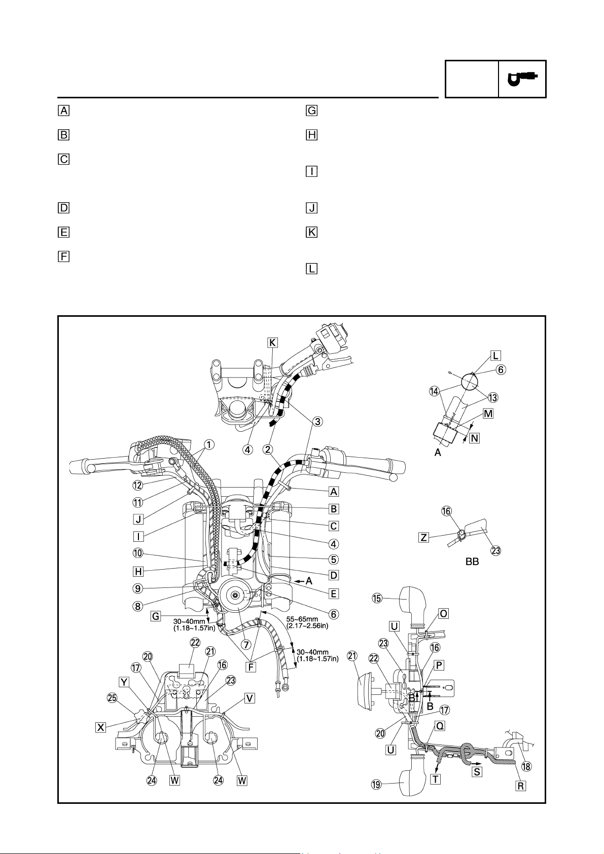
Fasten the horn lead to the upper side of the under
bracket as shown in the drawing. Cut the clamp tip
leaving 3 ~ 8 mm (0.12 ~ 0.31 in).
10 mm (0.39 in)
Fasten the turn signal light lead (right) together
with the coupler to the stay 1.
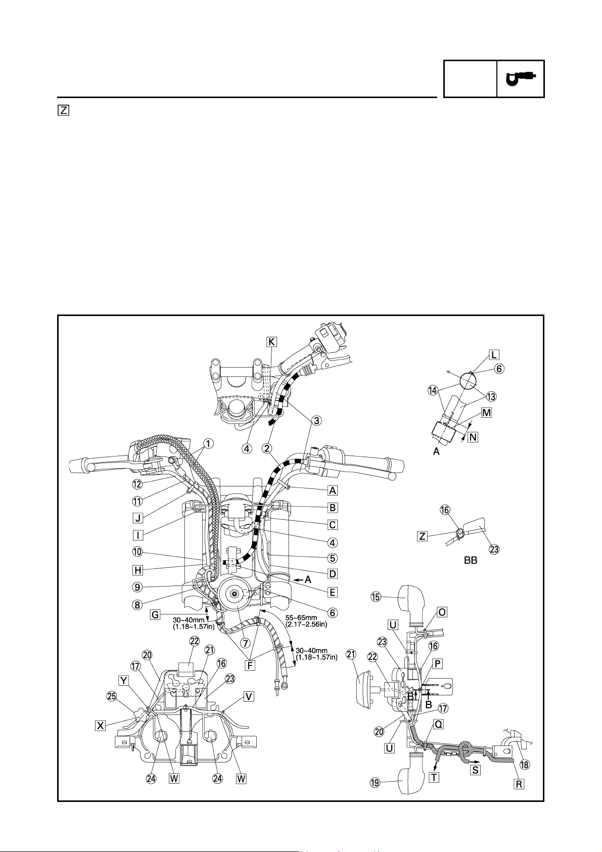
Clamp the white tape of headlight sub-wire harness to the stay 1. (For detail of the clamp, refer to
section BB.)
Fasten the wire harness and turn signal light lead
(left) together with the coupler to the stay 1.
And locate the turn signal light lead, under the wire
harness.
Route the wire harness through the outside of the
bolt.
To the headlight relay.
To the ECU.
After the clamping, direct the band point to the
front.
Clamp the headlight sub-wire harness to the stay 1
with a band.
Clamp the headlight sub-wire harness to the dent
in the stay 1.
Route the all leads through inside of the headlight
adjusting knob. Because of the protruding of the
wire harness, it does not have to become the disturbance of operation of the headlight adjusting
knob.
Clamp the meter lead, indicator light lead, headlight sub-wire harness to the stay 1 with a band.
10
Page 19
Fasten the headlight sub-wire harness with the
clamp that is passed through the center hole of
stay 1.
CABLE ROUTING
SPEC
11
Page 20

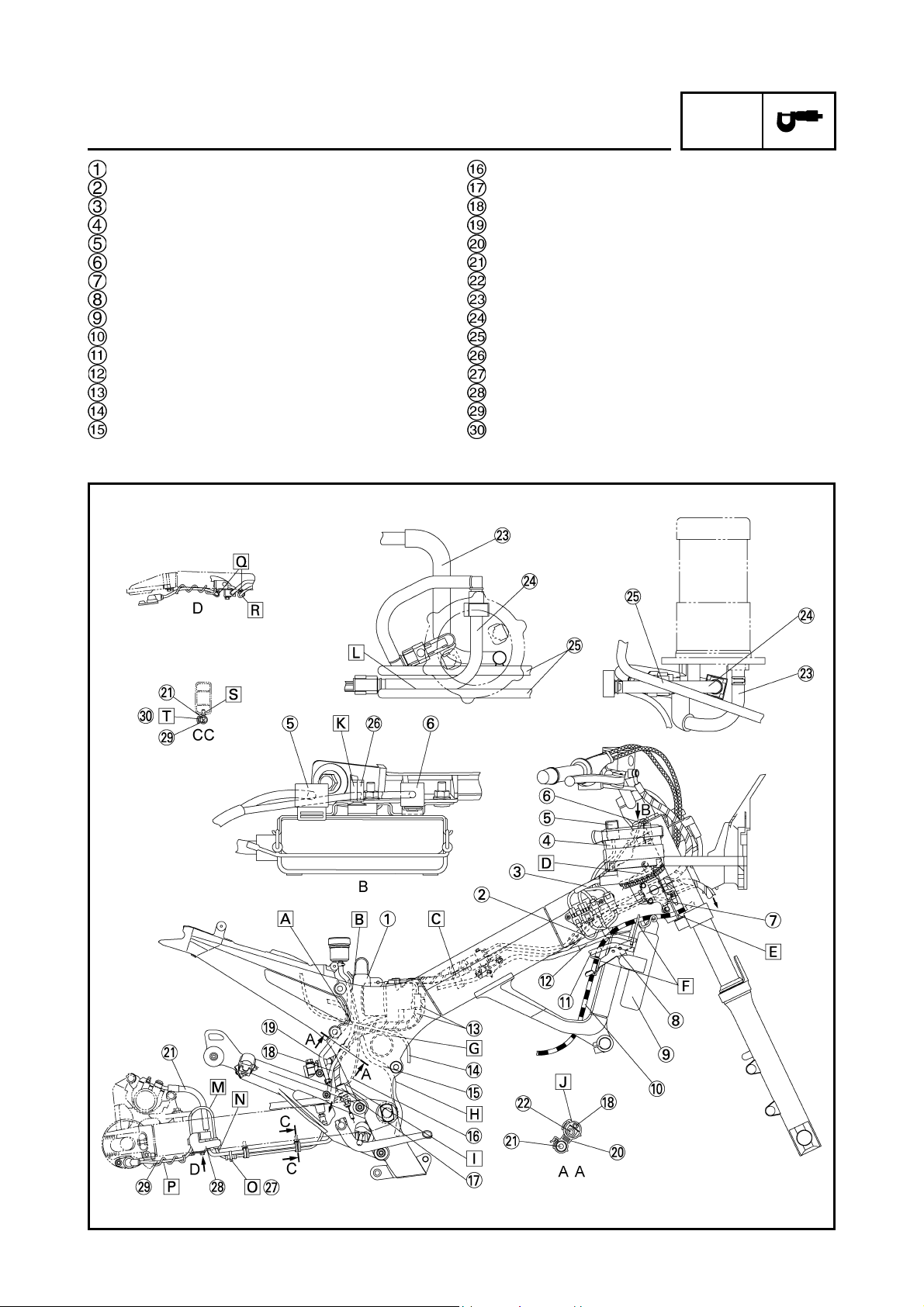
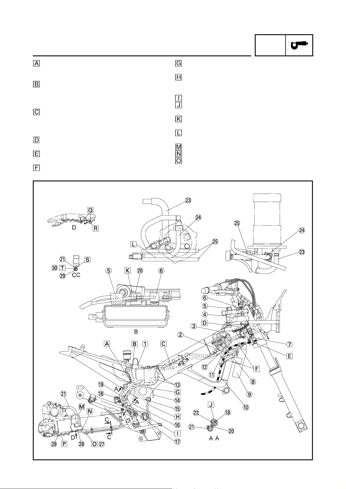
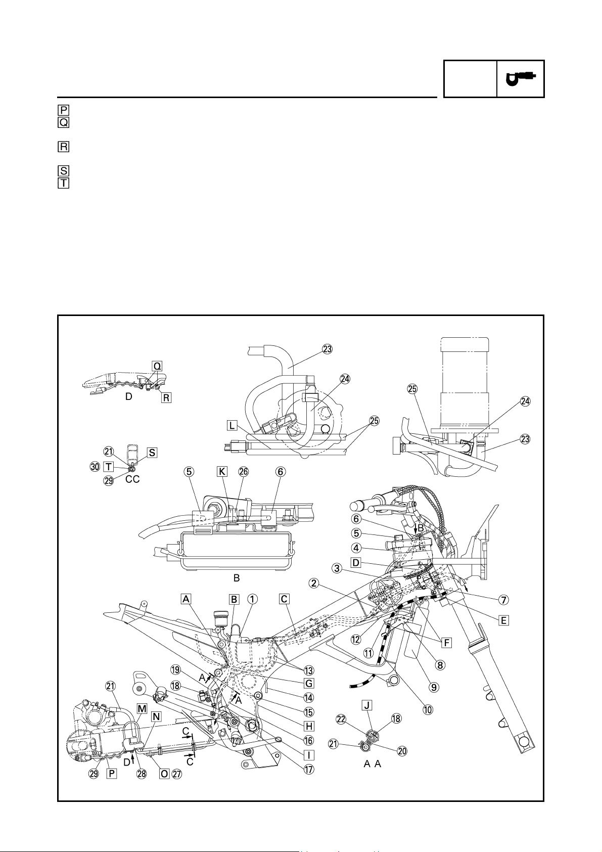
CABLE ROUTING
SPEC
Stay 3
Ignition coil assembly
Neutral switch lead
O
sensor lead
2
Speed sensor lead
Sidestand switch lead
Pickup coil lead
Fuel tank drain hose
Air filter drain hose
Coolant reservoir tank drain
hose
Battery negative lead
Seat lock cable
Immobilizer coupler
Joint coupler
Tail/brake light lead
Rear turn signal light
Rear turn signal light lead
Rectifier/regulator lead
Coolant reservoir tank
Rear shock absorber
Swingarm
Sidestand switch
O
sensor
2
Cylinder identification sensor
lead
Turn signal light relay
Headlight relay
Main relay
Front wheel sensor
ECU
ECU lead
Stay 1
6 poles water proof coupler
Boss
Starter motor lead
Frame
Engine
Oil pipe
12
Page 21

CABLE ROUTING
SPEC
To the headlight.
Route the 6 poles water proof coupler through
inside of the ECU lead, and the 12 poles coupler
through outside of the ECU lead.
Connect the headlight sub-wire harness coupler in
front of ECU and make it not to route above the
ECU lead.
Fasten the wire harness to the stay 1 with a clamp.
Clamp position shall be at the position shown in
the drawing 1. The knot should be faced to the outside of the vehicle.
Insert the terminal (black) of the ignition coil lead
as shown in the drawing.
Pass the cylinder identification sensor lead above
the left radiator hose.
Pass the rectifier/regulator lead above the frame
cross tube.
Route the tail/ brake light lead through the guides
(3 places) of the tail/brake lgiht bracket.
Fasten the tail/brake light lead at outside of the
frame with a clamp. After connecting the tail/ brake
light lead coupler, insert the surplus wiring
between frame, and positioning without routing
above the frame.
Fasten the rectifier/regulator lead with the clamp
installed with the rear fender. The clamp tip should
face the inner side of the vehicle.
13
Page 22

CABLE ROUTING
SPEC
Route the fuel drain hoses (2 hoses), air filter drain
hose, and coolant reservoir tank drain hose trough
the clamp. For the fuel drain hose, the white paint
mark should be under the clamp. The position is
regardless of ranks. Arrange the end of coolant
reservoir tank drain hose, air filter case drain hose
and fuel drain hose from the clamp.
The O
boss seat face to the outside of the vehicle.
Fasten the neutral switch lead, O
speed sensor lead, sidestand switch lead and
rectifier/regulator lead with the clamp as shown in
the drawing. Cut the clamp tip leaving 3 ~ 8 mm
(0.12 ~ 0.31 in) and make if face to the outside of
the vehicle.
sensor lead should not stick out from the
2
sensor lead,
2
Less than 20 mm (0.79 in)
Route the spark plug lead for the right cylinder
below the water pipe and behind the hose for the
air cut-off valve.
Route the front wheel sensor lead inside the vehicle and secure it to the front brake hose with a
clamp.
Pass the front wheel sensor lead through the cable
holder tightened together with the front brake caliper.
Fasten the cylinder identification sensor lead to the
inner side of the frame with a clamp.
Pass the front wheel sensor lead between the front
brake caliper and front brake hose.
14
Page 23
Pass the harness for the relay between ECU and
the main relay.
Fasten the ECU lead with the clamp installed to
the plate of front side hole. Align the positioning
tape and the clamp. Install the clamp to the out
side of plate.
Insert the terminal (white) of the spark plug lead as
shown in the drawing.
Pass the fuel drain hose coolant reservoir tankdrain hose and air filter drain hose behind the battery negative lead.
Route the fuel drain hoses (2 hoses), air filter drain
hose and coolant reservoir tank drain hose
through the guide located behind the swingarm
head pipe. Do not make hoses to cross in the area
between D and E.
CABLE ROUTING
SPEC
15
Page 24
CABLE ROUTING
SPEC
Seat bracket
Front wheel sensor lead
ECU (ABS) sub-wire harness
ECU (ABS)
Radiator fan motor relay
ABS check coupler
Brake hose holder
Stay 2
Radiator
Clutch cable
Thermo wax hose
Coolant reservoir tank hose
Rear brake hose
Starter motor lead
Hydraulic unit drain hose
Rear brake light switch lead
Rear brake light switch
Rear wheel sensor lead
Brake fluid reservoir hose
Clamp
Rear brake hose (OUT)
Rear brake hose (IN)
Fuel tank return hose
Fuel hose
Fuel tank drain hose
Clamp
Clamp
Brake hose holder
Rear wheel sensor lead
Clamp
16
Page 25
CABLE ROUTING
SPEC
The right and left positions for the starter motor
lead and rear wheel sensor lead can be accepted
in random oder.
Pass the brake fluid reservoir hose and the rearbrake light switch lead through the gap between
the rear fender and rear frame and route it behind
the seat bracket.
Clamp the coolant reservoir tank hose and brake
hose.
Clamping position should be behind the protector
and of the coolant reservoir tank hose.
Route the throttle cables and right handlebar
switch lead inside of the brake hose holder.
Route the clutch cable through the guide of brake
hose holder.
Route the clutch cable through the guide of stay 2.
Route the rear brake hose and starter motor lead
over the frame cross tube.
Route the hydraulic unit drain hose behind the
cross tube, front of the oil hose and also front of
the pivot shaft.
Direct the rear brake light switch lead to the front.
Clamp the grommet parts of the rear brake hose
and rear wheel sensor lead.
Clamp the ABS check coupler lead. Either upward
or downward direction of pawl is acceptable.
Pass the fuel hose between the fuel tank drain
hoses
Route by the outside of the brake hose.
Ensure that the leads are not folded.
Point the tip of the clamp downward and cut the
surplus part leaving 0 ~ 5 mm (0 ~ 0.20 in).
17
Page 26
Route inside the brake hose holder.
Attach the clamp so that its opening section faces
in the direction indicated in the drawing.
Clamp the grommet which is attached to the sensor lead.
Make sure to insert it to the deepest point.
Make sure to catch more than 3 notches. Install
the pawl so that it points to the outside of the vehicle.
CABLE ROUTING
SPEC
18
Page 27

CABLE ROUTING
SPEC
Throttle cables
Handlebar switch lead (right)
Front brake hose
Stay
Front wheel sensor lead
Thermo wax hose
Intake vacuum hose
Sub-wire harness (air filter case)
Oil level switch lead
Hydraulic unit lead
Coolant reservoir tank hose
Hydraulic unit assembly
Fail-safe relay
Rear brake light switch lead
Battery
Rectifier/regulator
Rear wheel sensor lead
Starter motor lead
Battery band
Battery positive lead
Lean angle cut-off switch
Atmospheric pressure sensor
Fuse (main)
Starter relay
Rear turn signal light lead (right)
Rear turn signal light (right)
Tail/brake light lead
Tail/brake light
Rear turn signal light lead (left)
19
Page 28
CABLE ROUTING
SPEC
Rear turn signal light (left)
Joint coupler
Immobilizer coupler
Seat lock cable
Fuse box
Battery negative lead
Hydraulic unit motor coupler
Coolant reservoir tank drain hose
Fuel pump lead 2
Fuel pump lead 1
Sub-wire harness (throttle body)
Radiator fan motor lead
Cylinder identification sensor lead
Hose 1
Bracket 1
Air induction system lead
Coolant temperature sensor lead
Cover 2
Main switch lead and immobilizer lead
Left handlebar switch lead
Boot
Frame
Wire harness
Intake vacuum hose (Joint section)
Front brake hose (IN)
Front brake hose (OUT)
Clamp
20
Page 29

CABLE ROUTING
SPEC
Put the cover on the coupler for the immobilizer
lead and wire harness.
Install the projection part of the coupler pointing to
the connector housing 2.
Align the projection part of the connector housing
2 with the hole of the locking bracket.
Attach the boot over the immobilizer coupler.
To the air induction system.
To the ECU (ABS).
To the air filter case.
Route the sub-wire harness (air filter case) and
intake vacuum hose over or side by the brake
hose.
To the oil tank.
Route the starter motor lead and rear wheel sensor
lead under the rear frame attaching boss section.
Route the starter motor lead and rear wheel sensor lead by the right of the battery. The upper and
lower positions of the leads can be accepted in
random order.
Route the battery positive lead under the battery
band. (secure with a band)
Pass the rear turn signal light lead (right) through
the right hole of the fender.
Pass the rear turn signal light leads (right and left)
through the clamp installed to the rear fender.
Adjust the length of the rear turn signal light lead
(left) by folding and then bundle it.
Pass the rear turn signal light lead (left) through
the left hole of the fender.
Pass the rear turn signal light leads (right and left)
between the ribs of the rear fender.
21
Page 30
CABLE ROUTING
SPEC
Pass the seat locking cable through the hole section of the seat bracket of the rear frame. Either
direction of the seat locking cable can be
accepted.
Set the immobilizer coupler and joint coupler
between the ribs of the rear fender.
Route the battery negative lead (black lead) above
the seat locking cable.
Route the battery positive lead (red lead) below
the seat locking cable.
Route the battery positive lead together with the
rear wheel sensor lead and starter motor lead as
shown in the illustration.
Route the battery negative lead above the battery.
Route the rear brake light switch lead below the
battery band. (secure with a band.)
Clamp the coolant reservoir tank hose to the
hydraulic unit bracket.
To the fuel pump.
Fasten the wire harness to the inner side of the
frame with the harness wrapping clamp.
Arrange to route the throttle cable so that its
upper side is the return cable and lower side for
the pulling cable.
To the throttle body.
Route the wire harness, cylinder identification
sensor lead and radiator fan motor lead under
the bracket 1.
Route the cylinder identification sensor lead and
radiator fan motor lead above the radiator hose.
To the radiator.
22
Page 31

CABLE ROUTING
SPEC
Bundle the coolant temperature sensor lead and
air induction system lead with the clamp. Cut the
clamp tip leaving 3 ~ 8 mm (0.12 ~ 0.31 in).
To the headlight.
Secure the wire harness to the holes at the internal left side and right side of the cover 2 with the
harness wrapping clamp.
Bundle the main switch lead, immobilizer lead,
left handlebar switch lead and right handlebar
switch lead with the clamp. Point the tip of the
clamp to the front side and set it between cover
and wire harness. Place the clamp at the right
side of the vehicle from the coupler as shown in
the illustration.
Fasten the cylinder identification sensor lead
and radiator fan motor lead to the frame with the
clamp as shown in the illustration. Point the tip of
the clamp to the downside.
Clamp it pointing the coolant reservoir tank hose
to the outside and the throttle body hose to the
inside. Position the clamp opening at the inside.
After binding a clamp, make sure to insert the
excessive part to the gap with the frame.
Clamp the coolant reservoir tank hose and brake
hose.
23
Page 32

CABLE ROUTING
SPEC
Intake vacuum hose joint
Clip
Intake vacuum hose
Clamp (fuel pump side)
Clamp (injector side)
Air filter case
Air filter drain hose
Fuel pump
Fuel hose
Fuel tank return hose
Hose
Filter
Stay
Throttle body
Hose clamp (carburetor joint lowerside)
Carburetor joint
Hose clamp (carburetor joint upper side)
Connect the intake vacuum hose joint of the air filter system assembly side and the pipe of the throttle body side.
Make sure to match the white paint mark to the
position right overhead.
Insert the hose until its end contacts the component. Point the pawl of the clip downward.
Install the clip so that its pawl is oriented within the
rangeshown in the drawing.
To assemble to the throttle body assembly, it is
allowed to apply the silicon liquid.
24
Page 33

CABLE ROUTING
SPEC
Insert the fuel tank return hose until its end contacts the component.
To assemble to the carburetor joint 1, it is allowed
to apply the engine oil.
Attach the hose clamp in this direction.
This part works as a stopper against drop-off.
Fuel piping connector attachment directions.
1. Insert the connector until the click sound is heard
and check that the connector does not come off.
Care should be taken so that the foreign matter is
not caught. (It is prohibited to wear cotton work
gloves during the operation.)
Always use hands to connect/disconnect the connector without using tools.
2. After the procedure item 1 as above is finished,
insert the clamp of the fuel pump side from the
lower side of the engine and check that the ,
and parts are completely equipped.
3. After the procedure item 1 as above is finished, lay
over the part of the injector side clamp from the
engine left side and insert the part from the
engine upper side while turning.
Check that the and parts are completely
equipped.
25
Page 34
CABLE ROUTING
SPEC
Rear brake hose (OUT)
Rear brake hose (IN)
Bracket 2
Frame
Bracket 1
Coolant reservoir tank
Wire harness assembly
Relay stay
Protector
Oil level sensor coupler
Hydraulic unit coupler
Front brake hose assembly (IN)
Front brake hose assembly (OUT)
Clamp
Drain plug
Hydraulic unit drain hose
Hydraulic unit motor coupler
Hydraulic unit assembly
Clamp (to the coolant reservoir tank hose)
Union bolt
Fail-safe relay
Brake hose holder
Fuel tank mold
26
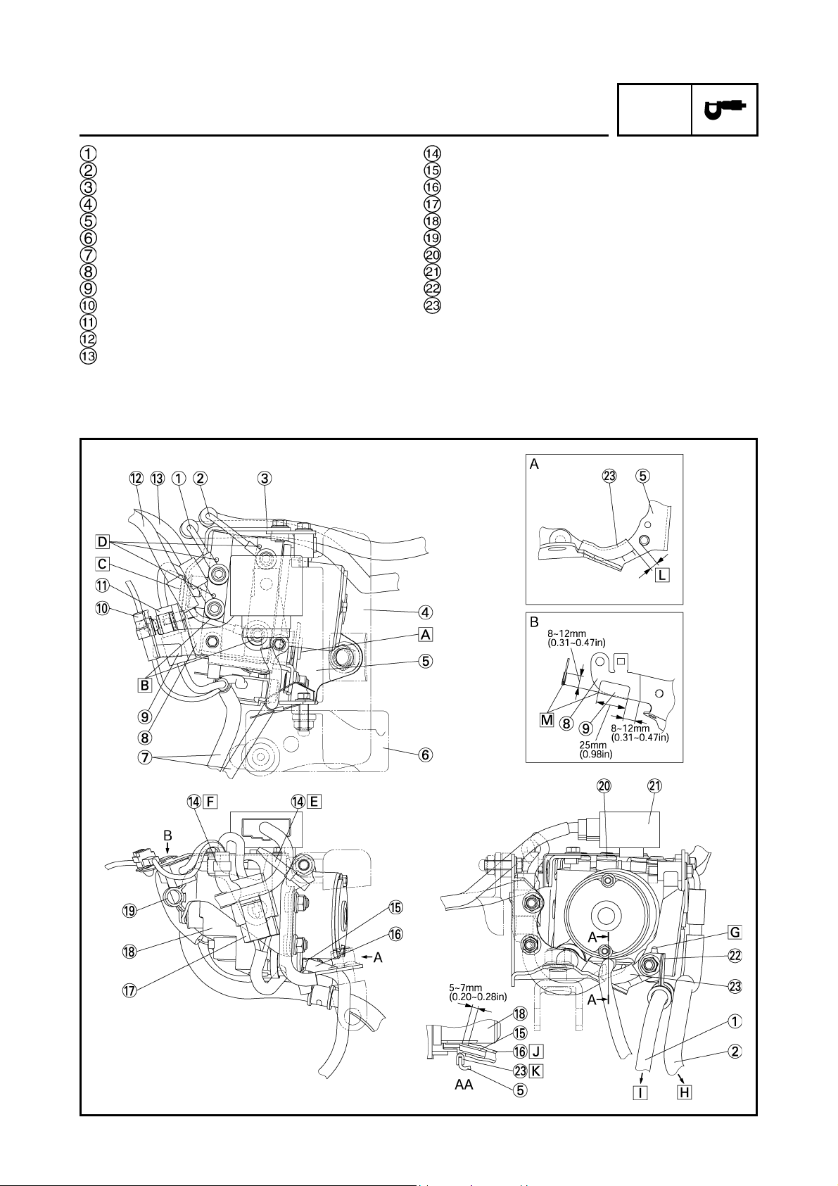
Page 35

CABLE ROUTING
SPEC
Insert the pin of the bracket 1 to the hydraulic unit
assembly.
Press front brake hose (IN) to the front brake hose
assembly (out) and tighten.
Insert the pin of the bracket 2 to the hydraulic unit
assembly.
Press brake hose to the detent pin of the hydraulic
unit assembly and tighten.
Clamp the wire harness assembly (for the fail-safe
relay) to the bracket 1.
Clamp the wire harness assembly. Clamp position
should be at the white taping section of the wire
harness assembly.
Insert brake hose holder projection to the hole.
To the rear brake master cylinder.
To the rear brake caliper.
Insert hydraulic unit drain hose to the deepest
point.
Fit the fuel tank mold in the bracket 1.
Keep approximately 7 ~ 10 mm (0.28 ~ 0.39 in)
away from the bolt position.
Upper and lower excessive parts should be
appressed. Appearance such as containing bubbles is no object.
27
Page 36
SWINGARM AND DRIVE CHAIN
EAS00709
SWINGARM AND DRIVE CHAIN
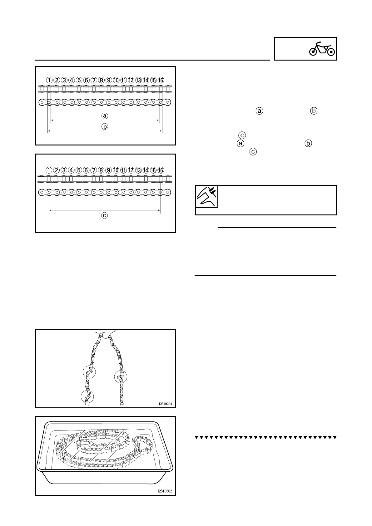
CHECKING THE DRIVE CHAIN
1. Measure:
• Measure the dimension between 15-links
on the inner side and outer side of the
roller and calculate the dimension between
pin centers.
• Dimension between pin centers = (Inner
dimension + Outer dimension )/2
• 15-link section of the drive chain
Out of specification → Replace the drive
chain, front drive sprocket and rear drive
sprocket as a set.
15-link drive chain section limit
(maximum)
239.3 mm (9.42 in)
NOTE:NOTE:
• While measuring the 15-link section, push
down on the drive chain to increase its tension.
• Perform this measurement at two or three different places.
CHAS
2. Check:
• drive chain
Stiffness → Clean and lubricate or replace.
3. Clean:
• drive chain
a. Wipe the drive chain with a clean cloth.
b. Put the drive chain in kerosene and remove
any remaining dirt.
c. Remove the drive chain from the kerosene
and completely dry it.
28
Page 37

SWINGARM AND DRIVE CHAIN
CAUTION:
This motorcycle has a drive chain with
small rubber O-rings between the drive
chain side plates. Never use high-pressure
water or air, steam, gasoline, certain solvents (e.g., benzine), or a coarse brush to
clean the drive chain. High-pressure methods could force dirt or water into the drive
chain’s internals, and solvents will deteriorate the O-rings. A coarse brush can also
damage the O-rings. Therefore, use only
kerosine to clean the drive chain.
CHAS
4. Check:
•O-rings
Damage → Replace the drive chain.
• drive chain rollers
Damage/wear → Replace the drive chain.
• drive chain side plates
Damage/wear → Replace the drive chain.
Cracks → Replace the drive chain and
make sure that the battery breather hose is
properly routed away from the drive chain
and below the swingarm.
5. Lubricate:
• drive chain
Recommended lubricant
Engine oil or chain lubricant
suitable for O-ring chains
6. Check:
• drive sprocket
• rear wheel sprocket
More than 1/4 tooth wear → Replace the
drive chain sprockets as a set.
Bent teeth → Replace the drive chain
sprockets as a set.
Correct
Drive chain roller
Drive chain sprocket
29
Page 38

ANTI-LOCK BRAKE SYSTEM (ABS)
CHAS
ANTI-LOCK BRAKE SYSTEM (ABS)
ABS OUTLINE
Yamaha ABS features
1. The Yamaha ABS (Anti-Lock Brake System) features a dual electronic control system, which acts
on the front and rear brakes independently.
2. The ABS features a compact and lightweight design to help maintain the basic maneuverability of
the motorcycle.
3. The hydraulic unit, which is the main component of the ABS, is centrally located on the motorcycle to increase mass centralization.
ABS layout
ABS warning light
Electronic control unit (ECU)
Fail-safe relay
Hydraulic unit
Rear brake caliper
Rear wheel sensor
Rear disc rotor
Front brake caliper
Front wheel sensor
Front disc rotor
30
Page 39

ANTI-LOCK BRAKE SYSTEM (ABS)
EAS00872
ABS
The operation of the Yamaha ABS brakes is
the same as conventional motorcycles, with a
brake lever for operating the front wheel brake
and a brake pedal for operating the rear wheel
brake.
When wheel lockup is detected during emergency braking, hydraulic control is performed
by the hydraulic system independently.
CHAS
EAS00873
Useful terms
• Wheel speed:
The rotation speed of the front and rear
wheels.
• Chassis speed:
The speed of the chassis.
When the brakes are applied, wheel speed
and chassis speed are reduced. However,
the chassis travels forward by its inertia
even though the wheel speed is reduced.
•Brake force:
The force applied by braking to reduce the
wheel speed.
• Wheel lock:
A condition that occurs when the rotation of
one or both of the wheels has stopped but
the motorcycle continues to travel.
•Side force:
The force on the tires which supports the
motorcycle when cornering.
31
Page 40

ANTI-LOCK BRAKE SYSTEM (ABS)
• Slip ratio:
When the brakes are applied, slipping
occurs between the tires and the road surface. This causes a difference between the
wheel speed and the chassis speed.
Slip ratio is the value that shows the rate of
wheel slippage and is defined by the following formula.
CHAS
Friction force between the
tire and road surface
Side force
Brake force
Less slippery
road surface
Controlling zone
Slip ratio (%)
Slip ratio =
Chassis speed – Wheel speed
Chassis speed
× 100 (%)
0%: There is no slip between the wheel
and the road surface. The chassis speed is
equal to the wheel speed.
100%: The wheel speed is “0”, but the
chassis is moving (i.e., wheel lock).
EAS00874
Brake force and motorcycle stability
When the brake pressure is increased, wheel
speed is reduced. Slip occurs between the tire
and the road surface and brake force is generated. The limit of this brake force is determined
by the friction force between the tire and the
road surface and is closely related to wheel
slippage. Wheel slippage is represented by the
slip ratio.
Therefore, side force is also closely related to
wheel slippage. See figure . If the brakes are
applied while keeping the proper slip ratio, it is
possible to obtain the maximum brake force
without losing much side force.
ABS allows full use of the tire capabilities even
on slippery road surfaces or less slippery road
surfaces. See figure .
Friction force between the
Slippery road surface
tire and road surface
Slip ratio (%)
32
Page 41

Wheel speed
Pressurized
Depressurized
Brake force
ANTI-LOCK BRAKE SYSTEM (ABS)
Motorcycle speed
CHAS
EAS00875
Wheel slip and hydraulic control
The ECU (ABS) calculates the wheel speed of
each wheel according to the rotation signal
received from the front and rear wheel sensors. In addition, the ECU (ABS) calculates the
motorcycle chassis speed and the rate of
speed reduction based on the wheel speed
values.
The difference between the chassis speed and
the wheel speed calculated in the slip ratio formula is equal to the wheel slip. When the
wheel has a tendency to lock, the wheel speed
is suddenly reduced. When the wheel slip and
the wheel speed reduction rate exceed the
preset values, the ECU (ABS) determines that
the wheel has a tendency to lock.
If the slip is large and the wheel has a tendency to lock (point A in the figure), the ECU
(ABS) reduces the brake fluid pressure in the
brake caliper and increases the pressure of the
brake fluid in the brake caliper when the tendency to lock has diminished (point B in the figure).
EAS00876
ABS operation and motorcycle control
If the ABS starts operating, there is a tendency
of the wheel to lock, and the motorcycle is
approaching the limit of control. To make the
rider aware of this condition, the ABS has been
designed to generate a reaction-force pulsating action in the brake lever or brake pedal.
NOTE:NOTE:
When the ABS is activated, a pulsating action
may be felt at the brake lever or brake pedal,
but this does not indicate a malfunction.
33
Page 42

ANTI-LOCK BRAKE SYSTEM (ABS)
CHAS
Friction force between the
tire and road surface
Side force
Brake force
Slip ratio (%)
The higher the cornering force on a tire, the
less traction there is available for braking. This
is true whether the motorcycle is equipped with
an ABS or not. Therefore, sudden braking
while cornering is not recommended. Excessive cornering force, which an ABS cannot prevent, could cause the tire to slip sideways.
WARNING
The braking of the motorcycle, even in the
worst case, is principally executed when
the motorcycle is advancing straight ahead.
During a turn, sudden braking is liable to
cause a loss of traction of the tires. Even in
motorcycles equipped with an ABS, overturning of the motorcycle cannot be prevented if it is braked suddenly.
The ABS functions to prevent the tendency of
the wheel to lock by controlling the brake
hydraulic pressure. But, if there is a tendency
of the wheel to lock on a slippery road surface,
due to engine braking, the ABS may not be
able to prevent the wheel from locking.
WARNING
The ABS controls only the tendency of the
wheel to lock caused by applying the
brakes. The ABS cannot prevent wheel lock
on slippery surfaces, such as ice, when it is
caused by engine braking, even if the ABS
is operating.
34
Page 43

ANTI-LOCK BRAKE SYSTEM (ABS)
EAS00877
CHAS
Electronic ABS features
The Yamaha ABS (Anti-lock Brake System) has been developed with the most advanced electronic
technology.
The ABS control is processed with good response providing various travel conditions for motorcycles.
The ABS also includes a highly developed self-diagnostic function. The ABS detects any problem
conditions and allows normal braking even if the ABS is not operating properly.
When this occurs, the ABS warning light on the meter assembly comes on.
The ABS stores the malfunction codes in the memory of the ECU (ABS) for easy problem identification and troubleshooting.
ABS block diagram
Rear brake master cylinder
Hydraulic unit
Hydraulic pump
ABS motor
Buffer chamber
Hydraulic control valve
Front brake master cylinder
Rear brake caliper
Front brake caliper
ECU (ABS)
Rear wheel sensor
Front wheel sensor
ABS warning light
35
Page 44

ANTI-LOCK BRAKE SYSTEM (ABS)
EAS000878
ABS component functions
• Wheel sensors and sensor rotors
Wheel sensors detect the wheel rotation
speed and transmit the wheel rotation signal to
the ECU (ABS).
Each wheel sensor is composed of a permanent magnet and a coil. The wheel sensors are
installed in the sensor housing for each wheel.
Sensor rotors are pressed in the inner side
of the front and rear wheel hubs and rotate
with the wheels. The sensor rotors have 44
serrations inside and are installed close to the
wheel sensors. As the distance changes
between the top and bottom of the serrations
with the rotation of the wheels, inductive electromotive force is generated in the wheel sensors. Wheel rotation speed is detected based
on the frequency of this alternating voltage.
At high speed
At low speed
Wheel sensor
Sensor rotor
CHAS
• ABS warning light
The ABS warning light comes on to warn the
rider if a malfunction in the ABS occurs.
When the main switch is set to “ON”, the ABS
warning light comes on for 2 seconds to check
if the ABS warning light is disconnected and to
check if the ABS is operating properly, then
goes off.
CAUTION:
If the rear wheel is raced with the motorcycle on the centerstand, the ABS warning
light may flash or come on. If this occurs,
set the main switch to “OFF”, then back to
“ON”. The ABS operation is normal if the
ABS warning light comes on for 2 seconds,
then goes off.
ABS warning light
36
Page 45

ANTI-LOCK BRAKE SYSTEM (ABS)
EAS00879
• Hydraulic unit
The hydraulic unit is composed of a hydraulic control valve (solenoid valve, flow control
valve), a buffer chamber, and a hydraulic pump
for each brake and an ABS motor. The hydraulic unit adjusts the front and rear wheel brake
fluid pressure to control the wheel rotation
speed according to signals transmitted from
the ECU (ABS).
CHAS
To rear brake master cylinder
Hydraulic pump
ABS motor
Buffer chamber
Hydraulic control valve
To front brake master cylinder
To the rear brake caliper
To the ECU (ABS)
To the front brake caliper
37
Page 46

ANTI-LOCK BRAKE SYSTEM (ABS)
• Hydraulic control valve
The hydraulic control valve is composed of
a flow control valve and solenoid valve.
When the ABS is activated, the flow control
valve regulates the flow of brake fluid to
each brake and the solenoid valve
decreases and increases the brake fluid
pressure.
1) When the brakes are operated normally, the
solenoid valve is closed, the spool of
the flow control valve does not move, and
the hydraulic line between the brake master
cylinder and brake caliper is open.
CHAS
2) When the ABS is activated, the solenoid
valve is opened by the power supplied
from the ECU (ABS) signals to decrease
the brake fluid pressure and the spool of
the flow control valve is moved toward the
solenoid valve.
3) When the ECU (ABS) stops transmitting
signals to decrease the brake fluid pressure, the solenoid valve closes and the
brake fluid is pressurized again. Pressurizing the brake fluid again, while the ABS is
activated, limits the flow of the brake fluid
with the movement of the flow control valve
spool and provides a gradual pressure
increase.
Orifice
Solenoid valve
Spool
Flow control valve
38
Page 47

ANTI-LOCK BRAKE SYSTEM (ABS)
• Electronic control unit (ECU)
The ECU (ABS) controls the ABS and is
installed inside the right cowling. To protect the
ECU (ABS) from water damage, it is protected
by a cover .
CHAS
39
Page 48

ANTI-LOCK BRAKE SYSTEM (ABS)
CHAS
As shown in the block diagram below, the ECU (ABS) receives wheel sensor signals from the front
and rear wheels and also receives signals from other monitor circuits. Both a main microcomputer
and a sub microcomputer are installed in the ECU (ABS) to provide mutual monitoring.
Battery
Engine stop switch
Starting circuit cut-off relay
Sidestand switch
Starter relay
Starter motor
Start switch
Front wheel sensor
Rear wheel sensor
Main fuse
Main switch
Generator
Rectifier/regulator
ABS fuse
ABS motor fuse
ABS test coupler
ECU (ABS)
Rear brake light switch
Front brake light switch
Tail/brake light
Meter assembly
ABS warning light
Fail-safe relay
ABS motor relay
Solenoid relay
Hydraulic unit
ABS motor
Front solenoid
Rear solenoid
The necessary actions are confirmed by the motor monitor circuit and control signals are transmitted to the hydraulic unit and fail-safe relay.
40
Page 49

ANTI-LOCK BRAKE SYSTEM (ABS)
• ABS control operation
The ABS control operation performed in the
ECU (ABS) is divided into the following two
parts.
• Hydraulic control
• Self-diagnosis
These operations are performed once every
8/1,000 of a second. When a failure is
detected in the ABS, a malfunction code is
stored in the memory of the ECU (ABS) for
easy problem identification and troubleshooting.
NOTE:NOTE:
Some types of failures are not recorded in the
memory of the ECU (ABS) (e.g., a drop in battery voltage).
Software operation flow
Set the main switch to “ON”.
Initialize
Self-diagnosis (when static)
Self-diagnosis (when riding)
Receive signals
Control operation
Depressurize/pressurize
CHAS
8/1,000 of a second
41
Page 50

ANTI-LOCK BRAKE SYSTEM (ABS)
CHAS
• Fail-safe relay
The fail-safe relay controls the power supply of
the hydraulic unit and is located beside the
hydraulic unit.
Fail-safe relay
Composition and operation
The fail-safe relay is composed of the solenoid relay and ABS motor relay . The solenoid relay
is activated (continuous) by signals transmitted from the ECU (ABS). As a result, the solenoid valve
can be operated.
If a malfunction occurs in the circuit, the solenoid relay is deactivated and it becomes impossible for
the solenoid valve to reduce the hydraulic pressure of the brake fluid and normal braking is
resumed.
The ABS motor relay is also activated by signals transmitted from the ECU (ABS) and operates
simultaneously when the ABS starts to reduce the hydraulic pressure of the brake fluid.
If the solenoid relay is turned off, the motor relay is also deactivated and the motor stops operating if
there is a malfunction.
Solenoid relay
ABS motor relay
Solenoid valve
Electric control unit (ECU)
Pump motor relay coil
Pump motor monitor
ABS warning light
Fail-safe relay coil
Rear solenoid
Front solenoid
42
Power
Fail-safe relay
Hydraulic unit
Page 51

ANTI-LOCK BRAKE SYSTEM (ABS)
CHAS
ABS operation
The ABS hydraulic circuit consists of two systems: the front wheel and rear wheel. The following
describes the front system only.
• Normal braking (ABS not activated)
When the ABS is not activated port D of the solenoid valve is closed because a control signal has
not been transmitted from the ECU (ABS) and port A and port B of the flow control valve are
open. Therefore, when the brake lever is squeezed, the hydraulic pressure in the brake master cylinder increases and the brake fluid is sent to the brake caliper via port A and port B.
At this time, the inlet and outlet check valves of the pump close the lines and brake fluid is not sent.
As a result, the brake master cylinder directly pressurizes the brake caliper during normal braking.
When the brake lever is released, the brake fluid in the brake caliper returns to the brake master cylinder via port A and port B.
43
Brake master cylinder
Brake light switch
ABS motor
Pump
Buffer chamber
Flow control valve
Por t A
Spool
Por t B
Orifice
Por t D
Solenoid valve
Por t C
Brake caliper
ECU (ABS)
ABS warning light
Brake fluid pressure
Time
Repressurizing
Page 52

ANTI-LOCK BRAKE SYSTEM (ABS)
CHAS
• Emergency braking (ABS activated)
1) Depressurized state
When the front wheel is about to lockup, port D of the solenoid valve is opened by the
“depres-surization” signal transmitted from the ECU (ABS). When this occurs, the spool of the
flow control valve compresses the return spring to close port B . Brake fluid that has entered
through port A is restricted by the orifice and the brake fluid is sent to the brake caliper via
port C and port D , and the buffer chamber. As a result, the hydraulic pressure in the brake
caliper is reduced.
The brake fluid stored in the buffer chamber is pumped back to the brake master cylinder by the
fluid pressure pump linked to the pump motor.
44
Brake master cylinder
Brake light switch
ABS motor
Pump
Buffer chamber
Flow control valve
Por t A
Spool
Por t B
Orifice
Por t D
Solenoid valve
Por t C
Brake caliper
ECU (ABS)
ABS warning light
Brake fluid pressure
Time
Repressurizing
Page 53

ANTI-LOCK BRAKE SYSTEM (ABS)
CHAS
2) Pressurized state
Port D is closed by the “pressurization” signal transmitted from the ECU (ABS). Before this
occurs, the spool of the flow control valve has compressed the return spring to close port B .
Brake fluid that has entered through port A is further restricted by the orifice and the brake
fluid is sent to the brake calipers via port A and port C . At this time, the brake is pressurized at a constant speed regardless of the brake fluid pressure level since restriction of port A
changes so that a constant pressure difference is maintained between chamber A and chamber B of the flow control valve.
45
Brake master cylinder
Brake light switch
ABS motor
Pump
Buffer chamber
Flow control valve
Por t A
Spool
Por t B
Orifice
Por t D
Solenoid valve
Por t C
Brake caliper
ECU (ABS)
ABS warning light
Brake fluid pressure
Time
Repressurizing
Chamber A
Chamber B
Page 54

Main switch Main switch
ABS warning
light
ABS warning
light
OFF ON
Goes off
Comes on
Goes off
Comes on for
2 seconds.
Preparation
Comes on
ANTI-LOCK BRAKE SYSTEM (ABS)
EAS00880
Self-diagnosis function
• ABS warning light
The ABS warning light comes on when a
malfunction is detected by the ABS self-diagnosis. It is located in the meter assembly.
• Instances when the ABS warning light
comes on
1) The ABS warning light comes on when the
main switch is set to “ON”.
Goes off
The ABS warning light comes on for 2 seconds while the ABS is performing a selfdiagnosis, then goes off if there are no
problems.
2) The ABS warning light comes on while
riding.
If the ABS warning light comes on while
riding, a malfunction has been detected in
the ABS. The ABS hydraulic control will not
be performed. The ABS will have recourse
to manual braking if this occurs.
3) The ABS warning light flashes while riding.
If the ABS warning light flashes while riding,
there is no problem with the function of the
ABS. However, the ECU (ABS) input has
unstable factors. (For details, refer to
“TROUBLESHOOTING”.)
NOTE:NOTE:
The ABS warning light comes on or flashes if
the motorcycle is ridden with the test coupler
adaptor connected to the test coupler.
CHAS
ABS warning
light
Preparation
46
Page 55

ANTI-LOCK BRAKE SYSTEM (ABS)
4) The ABS warning light flashes and malti-
function code
tion display when a test coupler adaptor
is connected to the 4-pin test coupler for
troubleshooting the ABS.
The 4-pin test coupler can be accessed by
removing the side cowling (right).
When the test coupler adaptor is connected to
the 4-pin test coupler, the ABS warning light
starts flashing and the multifunction display
indicates all the maltifunction codes recorded
in the ECU (ABS).
Test coupler adaptor
90890-03149
NOTE:NOTE:
The ABS warning light comes on or flashes if
the motorcycle is ridden with the test coupler
adaptor connected to the test coupler.
is indicated on the multifunc-
CHAS
47
Page 56

ANTI-LOCK BRAKE SYSTEM (ABS)
Cautions for operation
ABS warning light:
• When the main switch is set to “ON”, the ABS warning light comes on for 2 seconds, then goes
off.
• If the ABS warning light comes on while riding, stop the motorcycle, and then set the main switch
to “OFF”, then set the main switch to “ON”. The ABS operation is normal if the ABS warning light
comes on for 2 seconds, then off.
• If the rear wheel is raced with the motorcycle on the centerstand, the ABS warning light may flash
or come on. If this occurs, set the main switch to “OFF”, then back to “ON”. The ABS operation is
normal if the ABS warning light comes on for 2 seconds, then goes off.
• The ABS operation is normal if the ABS warning light flashes.
• Even if the ABS warning light remains on and does not go off or if it comes on after riding, conventional braking performance of the motorcycle is maintained.
ABS function:
• A brake system in which the hydraulic control has been performed by the ABS alerts a rider that
the wheels had a tendency to lock by generating a reaction-force pulsating action in the brake
lever or brake pedal. When the ABS is activated, the grip between the road surface and tires is
close to the limit. The ABS cannot prevent wheel lock* on slippery surfaces such as ice, when it is
caused by engine braking, even if the ABS is activated.
• The ABS is not designed to shorten the braking distance or improve the cornering performance.
• Depending on the road conditions, the braking distance may be longer compared to that of vehicles not equipped with an ABS. Therefore, ride at a safe speed and keep a safe distance between
yourself and other vehicles.
• The braking of the motorcycle, even in the worst case, is principally executed when the motorcycle is advancing straight ahead. During a turn, sudden braking is liable to cause a loss of traction
of the tires. Even motorcycles equipped with an ABS cannot be prevented from falling over if
braked suddenly.
• The ABS does not work when the main switch is set to “OFF”. The conventional braking function
can be used.
CHAS
* Wheel lock: A condition that occurs when the rotation of one or both of the wheels has stopped
but the motorcycle continues to travel.
48
Page 57

ANTI-LOCK BRAKE SYSTEM (ABS)
EAS00882
ABS COMPONENTS
Front brake hose (front brake master cylinder to
hydraulic unit)
ABS test coupler
ABS warning light
Front brake hose (hydraulic unit to front brake caliper)
Front wheel sensor
Front wheel sensor rotor
Electronic control unit (ECU)
CHAS
Rear brake hose (hydraulic unit to rear brake caliper)
Rear brake hose (rear brake master cylinder to
hydraulic unit)
Hydraulic unit
Rear wheel sensor rotor
Rear wheel sensor
Fuse box
Fail-safe relay
49
Page 58

ANTI-LOCK BRAKE SYSTEM (ABS)
EAS00889
FRONT WHEEL SENSOR AND SENSOR ROTOR
40 Nm (4.0 m•kg, 29 ft•lb)
40 Nm (4.0 m•kg, 29 ft•lb)
72 Nm (7.2 m•kg, 52 ft•lb)
20 Nm (2.0 m•kg, 14 ft•lb)
CHAS
40 Nm (4.0 m•kg, 29 ft•lb)
40 Nm (4.0 m•kg, 29 ft•lb)
18 Nm (1.8 m•kg, 13 ft•lb)
18 Nm (1.8 m•kg, 13 ft•lb)
30 Nm (3.0 m•kg, 22 ft•lb)
Order Job/ Part Q’ty Remarks
Removing the front wheel sensor
and sensor rotor
Remove the parts in the order listed.
NOTE:NOTE:
Place the motorcycle on a suitable stand
so that the front wheel is elevated.
1 Brake caliper (left and right) 2
2 Front wheel sensor 1
3 Wheel axle pinch bolt 1 Loosen.
4 Front wheel axle 1
5 Collar (right) 1
6 Sensor housing 1
7 Brake disc (left and right) 2
8 Front wheel 1
For installation, reverse the removal
procedure.
50
Page 59

ANTI-LOCK BRAKE SYSTEM (ABS)
Maintenance of the front wheel sensor and
sensor rotor
• ABS wheel sensor and sensor rotor
CAUTION:
• Handle the ABS components with care
since they have been accurately adjusted.
Keep them away from dirt and do not subject them to shocks.
• The ABS wheel sensor cannot be disassembled. Do not attempt to disassemble
it. If faulty, replace with a new one.
CHAS
• Removing the front wheel sensor
1. Remove:
• brake hose holder
• front wheel sensor lead holder
• brake caliper
• front wheel sensor
CAUTION:
• Be sure not to contact the sensor electrode to any metal part when removing the
front wheel sensor from the sensor housing.
• Do not operate the brake lever when
removing the brake caliper.
• Checking the front wheel sensor and sensor rotor
1. Check:
• front wheel sensor
Cracks/ bends / distortion → Replace.
Iron powder/ dust → Clean.
51
Page 60

ANTI-LOCK BRAKE SYSTEM (ABS)
2. Measure:
• front wheel sensor resistance
Connect the pocket tester (Ω × 1k) to the
terminals of the front wheel sensor coupler.
Tester positive probe → Terminal
Tester negative probe → Terminal
Regulated resistance
1.2 ~ 1.6 kΩ at 20 °C
Out of specification → Replace.
3. Check:
• front wheel sensor rotor
Cracks/ damage → Replace the front wheel
assembly.
NOTE:NOTE:
The wheel sensor rotor of the motorcycle is
inserted under pressure by a special process
and cannot be replaced as a single unit. To
replace the sensor rotor, replace the wheel
assembly.
CHAS
• Installing the front wheel sensor
1. Install:
• front wheel
NOTE:NOTE:
Align the slot in the sensor housing with the
projection of the front fork before assembly.
CAUTION:
Make sure there are no foreign materials in
the wheel hub. Foreign materials cause
damage to the inner sensor rotor and front
wheel sensor.
52
Page 61

ANTI-LOCK BRAKE SYSTEM (ABS)
2. Install:
• front wheel sensor
• front wheel sensor lead holder
• brake caliper
• brake hose holder
NOTE:NOTE:
When installing the front wheel sensor, check
the wheel sensor lead for twists and the sensor
electrode for foreign materials.
CAUTION:
To route the front wheel sensor lead, refer
to “CABLE ROUTING”.
3. Check:
• front wheel sensor installation
Check if the wheel sensor housing is
installed properly. Refer to “P51 Maintenance of the front wheel sensor and sensor
rotor”.
CHAS
30 Nm (3.0 m•kg, 22 ft•lb)
40 Nm (4.0 m•kg, 29 ft•lb)
53
Page 62

ANTI-LOCK BRAKE SYSTEM (ABS)
EAS00890
REAR WHEEL SENSOR AND SENSOR ROTOR
CHAS
40 Nm (4.0 m•kg, 29 ft•lb)
27 Nm (2.7 m•kg, 20 ft•lb)
30 Nm (3.0 m•kg, 22 ft•lb)
150 Nm (15.0 m•kg, 108 ft•lb)
Order Job/ Part Q’ty Remarks
Removing the rear wheel sensor and
sensor rotor
Remove the parts in the order listed.
NOTE:NOTE:
Place the motorcycle on a suitable stand
so that the rear wheel is elevated.
1 Brake caliper 1
2 Brake caliper bracket bolt 1
3 Lock nut 2
4 Adjusting bolt 2
5 Rear wheel sensor 1
6 Wheel axle nut 1
7 Washer 2
8 Wheel axle 1
9 Adjusting block 2
10 Rear wheel 1
11 Sensor housing 1
For installation, reverse the removal
procedure.
54
Page 63

ANTI-LOCK BRAKE SYSTEM (ABS)
Maintenance of the rear wheel sensor and
sensor rotor
CAUTION:
• Be sure not to contact the sensor electrode to any metal part when removing the
front wheel sensor from the sensor housing.
• Do not operate the brake lever when
removing the brake caliper.
• Removing the rear wheel sensor
1. Disconnect:
• rear wheel sensor
2. Remove:
•clamp
• rear wheel sensor lead holder
CHAS
3. Remove:
• rear wheel sensor
CAUTION:
Be sure not to contact the sensor electrode
to any metal part when removing the rear
wheel sensor from the sensor housing.
• Checking the rear wheel sensor and sensor rotor
Refer to “Checking the front wheel sensor and
sensor rotor”.
55
Page 64

ANTI-LOCK BRAKE SYSTEM (ABS)
• Installing the rear wheel sensor
1. Install:
• rear wheel
NOTE:NOTE:
• Align the slot of the sensor housing
with the projection of the rear brake caliper
bracket , and then assemble them.
• After installation, check that the projection
of the rear brake caliper bracket is inserted
into the projection of the sensor housing.
CAUTION:
Make sure there are no foreign materials in
the wheel hub. Foreign materials cause
damage to the inner sensor rotor and rear
wheel sensor.
CHAS
2. Install:
• rear wheel sensor
30 Nm (3.0 m•kg, 22 ft•lb)
NOTE:NOTE:
When installing the rear wheel sensor, check
the rear wheel sensor lead for twists and the
sensor electrode for foreign materials.
CAUTION:
To route the rear wheel sensor lead, refer to
“CABLE ROUTING”.
3. Connect:
• rear wheel sensor coupler
• rear wheel sensor lead holder
•clamp
CAUTION:
To route the rear wheel sensor lead, refer to
“CABLE ROUTING”.
56
4. Check:
• rear wheel sensor installation
Check if the wheel sensor housing is
installed properly. Refer to “P55 Maintenance of the rear wheel sensor and sensor
rotor”.
Page 65

EAS00891
HYDRAULIC UNIT
ANTI-LOCK BRAKE SYSTEM (ABS)
CHAS
30 Nm (3.0 m•kg, 22 ft•lb)
30 Nm (3.0 m•kg, 22 ft•lb)
16 Nm (1.6 m•kg, 12 ft•lb)
16 Nm (1.6 m•kg, 12 ft•lb)
Order Job/ Part Q’ty Remarks
Removing the hydraulic unit
Remove the parts in the order listed.
Seat Refer to “SEAT” in chapter 3.
(Manual No.: 5PS1-AE1)
Fuel tank Refer to “FUEL TANK” in chapter 3.
(Manual No.: 5PS1-AE1)
ABS motor coupler/Hydraulic unit solenoid coupler
Fail-safe relay/Fail-safe relay coupler 1 / 1
1/1
Refer to “ECU (ABS) AND FAIL-SAFE
RELAY”.
Brake fluid Drain.
1 Union bolt/ copper washers 1/2
2 Front brake hose 1 (front brake master cylinder to hydraulic
unit)
3 Union bolt/ copper washers 1/2
4 Front brake hose 1 (hydraulic unit to front brake caliper)
5 Union bolt/ copper washers 1/2
57
Page 66

ANTI-LOCK BRAKE SYSTEM (ABS)
CHAS
30 Nm (3.0 m•kg, 22 ft•lb)
30 Nm (3.0 m•kg, 22 ft•lb)
16 Nm (1.6 m•kg, 12 ft•lb)
16 Nm (1.6 m•kg, 12 ft•lb)
Order Job/ Part Q’ty Remarks
6 Rear brake hose 1 (rear brake master cylinder to hydraulic
unit)
7 Union bolt/copper washers 1/2
8 Rear brake hose 1 (hydraulic unit to rear brake caliper)
9Nut 2
10 Hydraulic unit 1
11 Hydraulic unit bracket 2 1
For assembly, reverse the disassembly
procedure.
58
Page 67

ANTI-LOCK BRAKE SYSTEM (ABS)
Maintenance of the hydraulic unit
CAUTION:
Do not remove the hydraulic unit to check
the resistance of the solenoid valves and
the ABS motor for continuity.
WARNING
Refill with the same type of brake fluid that
is already in the system. Mixing fluids may
result in a harmful chemical reaction, leading to poor braking performance.
CAUTION:
• Handle the ABS components with care
since they have been accurately adjusted.
Keep them away from dirt and do not subject them to shocks.
• The ABS wheel sensor cannot be disassembled. Do not attempt to disassemble
it. If faulty, replace with a new one.
• Do not set the main switch to “ON” when
removing the hydraulic unit.
• Do not clean with compressed air.
• Do not reuse the brake fluid.
• Brake fluid may damage painted surfaces
and plastic parts. Therefore, always clean
up any spilt brake fluid immediately.
• Do not allow any brake fluid to contact the
couplers. Brake fluid may damage the
couplers and cause bad contacts.
• If the union bolts for the hydraulic unit
have been removed, be sure to tighten
them to the specified torque and bleed the
brake system.
CHAS
59
Page 68

ANTI-LOCK BRAKE SYSTEM (ABS)
• Checking the resistance of the solenoid
valves and ABS motor for continuity
CAUTION:
When check the hydraulic unit solenoid
relay and ABS motor, do not remove the
brake hoses.
1. Measure:.
• resistance of the solenoid valve (front)
Connect a pocket tester (Ω × 1) to the termi-
nals of the solenoid valve (front).
Tester positive probe → Terminal
Tester negative probe → Terminal
Solenoid valve resistance
2.96 ~ 3.20 Ω at 20 °C
Out of specification → Replace the hydraulic unit.
2. Measure:
• resistance of the solenoid valve (rear)
Connect the pocket tester (Ω × 1) to the ter-
minals of solenoid valve (rear).
Tester positive probe → Terminal
Tester negative probe → Terminal
CHAS
Solenoid valve resistance
2.96 ~ 3.20 Ω at 20 °C
Out of specification → Replace the hydraulic unit.
3. Check:
• ABS motor for continuity
Connect the pocket tester (Ω × 1) to the ter-
minals of the ABS motor coupler.
Tester positive probe → Terminal
Tester negative probe → Terminal
60
There is continuity.
No continuity → Replace the hydraulic unit.
Page 69

ANTI-LOCK BRAKE SYSTEM (ABS)
• Removing the hydraulic unit
1. Remove:
• brake hose (from the front brake master
cylinder)
• brake hose (to the front brake caliper)
• brake hose (from the rear brake master
cylinder)
• brake hose (to the rear brake caliper)
NOTE:NOTE:
Do not operate the brake lever and brake pedal
while removing the brake hoses.
CAUTION:
When removing the brake hoses, cover the
area around the hydraulic unit to catch any
spilt brake fluid. Do not allow the brake
fluid to contact other parts.
CHAS
2. Remove:
• hydraulic unit bracket 2
NOTE:NOTE:
Loosen the nuts in the proper sequence.
3. Remove:
• hydraulic unit
NOTE:NOTE:
To avoid brake fluid leakage and to prevent foreign materials from entering the hydraulic unit,
insert a rubber plug or a bolt (M10 × 1.25)
into each union bolt hole.
• Checking the hydraulic unit
1. Check:
• hydraulic unit
Cracks/ damage → Replace the hydraulic
unit.
61
Page 70

ANTI-LOCK BRAKE SYSTEM (ABS)
• Installing the hydraulic unit
Proceed in the reverse order of disassembly.
Pay attention to the following items.
1. Install:
• hydraulic unit bracket 2
NOTE:NOTE:
Tighten the nuts in the proper sequence.
2. Install:
• hydraulic unit
NOTE:NOTE:
Do not allow any foreign materials to enter the
hydraulic unit or the brake hoses when installing the hydraulic unit.
CAUTION:
CHAS
16 Nm (1.6 m•kg, 12 ft•lb)
Do not remove the rubber plugs or bolts
(M10 × 1.25) installed in the union bolt
holes before installing the hydraulic unit.
3. Remove:
• rubber plugs or bolts (M10 × 1.25)
4. Install:
• copper washer
• brake hose (to the rear brake caliper)
• brake hose (from the rear brake master
cylinder)
• brake hose (to the front brake caliper)
• brake hose (from the front brake master
cylinder)
• union bolt
30 Nm (3.0 m•kg, 22 ft•lb)
WARNING
The brake hoses to the front and rear brake
calipers can be distinguished by the rubber
at the end of each hose. Be sure to connect
each brake hose to the correct union bolt
hole.
CAUTION:
To route the front and rear brake hoses,
refer to “CABLE ROUTING”.
62
Page 71

ANTI-LOCK BRAKE SYSTEM (ABS)
5. Fill:
• brake master cylinder reservoirs
Recommended brake fluid
DOT 4
6. Bleed the brake system.
7. Check the operation of the hydraulic unit
according to the brake lever and the brake
pedal response. (Refer to “P68 Hydraulic
unit operation test 1”.)
CAUTION:
Always check the operation of the hydraulic unit according to the brake lever and the
brake pedal response.
8. Delete the malfunction codes. (Refer to
“P120 Deleting the malfunction codes”.)
9. Perform a trial run. (Refer to “P73 Trial
run”.)
CHAS
63
Page 72

ANTI-LOCK BRAKE SYSTEM (ABS)
HYDRAULIC ABS
EAS00892
Bleeding the ABS system
WARNING
Always bleed the brake system when the
brake related parts are removed.
CAUTION:
Bleed the brake system in the following
order.
1st: Front brake caliper
2nd: Rear brake caliper
•Brake lever
• Brake pedal
• Front brake hose (from the front brake
master cylinder)
• Rear brake hose (from the rear brake
master cylinder)
CHAS
64
Page 73
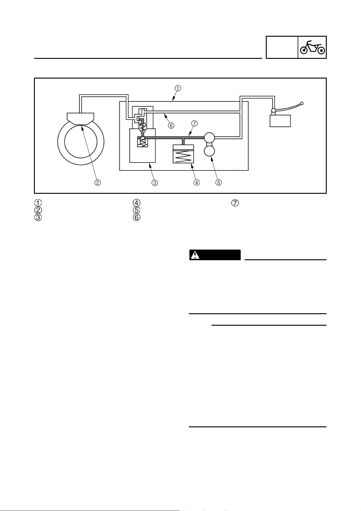
Bleeding instruction
ANTI-LOCK BRAKE SYSTEM (ABS)
CHAS
Hydraulic unit
Brake caliper
Solenoid valve
Buffer chamber
Hydraulic pump
Brake master cylinder pressure
EAS00134
Bleeding the ABS brake
WARNING
Bleed the ABS whenever:
• the system is disassembled.
• a brake hose is loosened, disconnected or
replaced.
• the brake fluid level is very low.
• brake operation is faulty.
NOTE:NOTE:
• Be careful not to spill any brake fluid or allow
the brake master cylinder reservoir or brake
fluid reservoir to overflow.
• When bleeding the ABS, make sure there is
always enough brake fluid before applying the
brake. Ignoring this precaution could allow air
to enter the ABS, considerably lengthening
the bleeding procedure.
• If bleeding is difficult, it may be necessary to
let the brake fluid settle for a few hours.
• Repeat the bleeding procedure when the tiny
bubbles in the hose have disappeared.
Hydraulic pump pressure
65
Page 74

ANTI-LOCK BRAKE SYSTEM (ABS)
1. Remove:
•seat
Refer to “SEAT” in chapter 3.
(Manual No.: 5PS1-AE1)
2. Bleed:
• ABS
a. Fill the brake fluid reservoir to the proper
level with the recommended brake fluid.
b. Install the diaphragm (brake master cylin-
der reservoir or brake fluid reservoir).
c. Connect a clear plastic hose tightly to
the bleed screw .
Front
Rear
d. Place the other end of the hose into a con-
tainer.
e. Slowly apply the brake several times.
f. Fully squeeze the brake lever or fully
depress the brake pedal and hold it in posi-
tion.
g. Loosen the bleed screw.
NOTE:NOTE:
Loosening the bleed screw will release the
pressure and cause the brake lever to contact
the throttle grip or the brake pedal to fully
extend.
CHAS
h. Tighten the bleed screw, and then release
the brake lever or brake pedal.
i. Repeat steps (e) to (h) until all of the air
bubbles have disappeared from the brake
fluid in the plastic hose.
j. Check the operation of the hydraulic unit.
Refer to “P68 Hydraulic unit operation test
1”.
CAUTION:
Make sure that the main switch is set to
“OFF” before checking the operation of the
hydraulic unit.
k. After operating the ABS, repeat steps (e) to
(i), and then fill the primary circuit with the
recommended brake fluid.
66
Page 75

ANTI-LOCK BRAKE SYSTEM (ABS)
l. Tighten the bleed screw to the specified
torque.
Bleed screw
6 Nm (0.6 m•kg, 4.3 ft•lb)
m. Fill the brake fluid reservoir to the proper
level with the recommended brake fluid.
Refer to “CHECKING THE BRAKE FLUID
LEVEL” in chapter 3.
(Manual No.: 5PS1-AE1)
WARNING
After bleeding the ABS, check the brake
operation.
CHAS
• Final check
Checking procedures
1. Check the brake fluid level in the brake
master cylinder reservoirs.
2. Check the wheel sensors for proper installa-
tion.
3. Perform hydraulic unit operation test 1 or 2.
4. Delete the malfunction codes.
5. Perform a trial run.
• Checking the brake fluid level of the brake
master cylinder reservoirs
1. Check:
• brake fluid level
Refer to “CHECKING THE BRAKE FLUID
LEVEL” in chapter 3.
(Manual No.: 5PS1-AE1)
• Checking the wheel sensors for proper
installation
1. Check if the front wheel sensor housing and
the rear wheel sensor housing are installed
correctly. (Refer to “P51 Maintenance of the
front wheel sensor and sensor rotor” and
“P55 Maintenance of the rear wheel sensor
and sensor rotor”.)
67
Page 76

ANTI-LOCK BRAKE SYSTEM (ABS)
2. Check:
• installation of the wheel sensors to the sensor housings (Refer to “P51 Maintenance of
the front wheel sensor and sensor rotor”
and “P55 Maintenance of the rear wheel
sensor and sensor rotor”.)
Wheel sensor
30 Nm (3.0 m•kg, 22 ft•lb)
Hydraulic unit operation test
The reaction-force pulsating action generated
in the brake lever and brake pedal when the
ABS is activated can be tested when the
motorcycle is stopped.
The hydraulic unit operation can be tested by
the following two methods.
• Hydraulic unit operation test 1: this test generates the same reaction-force pulsating
action that is generated in the brake lever
and brake pedal when the ABS is activated.
• Hydraulic unit operation test 2: this test
checks the function of the ABS after the
system was disassembled, adjusted, or serviced.
CHAS
• Hydraulic unit operation test 1
WARNING
Securely support the motorcycle so that
there is no danger of it falling over.
1. Place the motorcycle on the sidestand.
2. Set the main switch to “OFF”.
3. Remove:
•seat
Refer to “SEAT”.
(Manual No.: 5PS1-AE1)
• right side cowling
Refer to “FRONT COWLINGS”.
(Manual No.: 5PS1-AE1)
68
Page 77

ANTI-LOCK BRAKE SYSTEM (ABS)
4. Check:
• battery voltage
Battery voltage
Higher than 12.8 V
Lower than 12.8 V → Charge or replace the
battery.
NOTE:NOTE:
• If the battery voltage is lower than 12.8 V,
charge the battery and perform hydraulic unit
operation test 1.
• If the battery voltage is lower than 10 V, the
ABS warning light comes on and the ABS
does not operate.
CHAS
5. Connect the test coupler adaptor to the
test coupler .
Test coupler adaptor
90890-03149
6. Set the engine stop switch to “ ”.
7. Set the main switch to “ON”.
NOTE:NOTE:
After setting the main switch to “ON”, wait
(approximately 2 seconds) until the ABS warning light goes off.
8. Push the start switch for at least
onds.
4 sec-
CAUTION:
Do not operate the brake lever or the brake
pedal.
69
Page 78

ANTI-LOCK BRAKE SYSTEM (ABS)
9. After releasing the start switch, operate the
brake lever and the brake pedal simultaneously.
NOTE:NOTE:
• A reaction-force pulsating action is generated
in the brake lever 0.5 second after the
brake lever and the brake pedal are operated
simultaneously and continues for approximately 1 second.
• Be sure to continue to operate the brake lever
and brake pedal even after the pulsating
action has stopped.
CHAS
10.After the pulsating action has stopped in
the brake lever, it is generated in the brake
pedal 0.5 second after and continues for
approximately 1 second.
NOTE:NOTE:
Be sure to continue to operate the brake lever
and brake pedal even after the pulsating action
has stopped.
11.After the pulsating action has stopped in
the brake pedal, it is generated in the brake
lever 0.5 second after and continues for
approximately 1 second.
CAUTION:
• Check that the pulsating action is felt in
the brake lever, brake pedal, and again in
the brake lever, in this order.
• If the pulsating action is felt in the brake
pedal before it is felt in the brake lever,
check that the brake hoses are connected
correctly to the hydraulic unit.
• If the pulsating action is hardly felt in
either the brake lever or brake pedal,
check that the brake hoses are connected
correctly to the hydraulic unit.
70
Page 79

ANTI-LOCK BRAKE SYSTEM (ABS)
12.Set the main switch to “OFF”.
13.Remove the test coupler adaptor from the
test coupler.
14.Set the main switch to “ON”.
15.Set the engine stop switch to “ ”.
• Hydraulic unit operation test 2
WARNING
Securely support the motorcycle so that
there is no danger of it falling over.
1. Place the motorcycle on the centerstand.
2. Set the main switch to “OFF”.
3. Remove:
•seat
Refer to “SEAT”.
(Manual No.: 5PS1-AE1)
• right side cowling
Refer to “FRONT COWLINGS”.
(Manual No.: 5PS1-AE1)
4. Check:
• battery voltage
CHAS
Battery voltage
Higher than 12.8 V
Lower than 12.8 V → Charge or replace the
battery.
NOTE:NOTE:
• If the battery voltage is lower than 12.8 V,
charge the battery and perform hydraulic unit
operation test 2.
• If the battery voltage is lower than 10 V, the
ABS warning light comes on and the ABS
does not operate.
5. Connect the test coupler adaptor to the
test coupler .
Test coupler adaptor
90890-03149
71
Page 80

ANTI-LOCK BRAKE SYSTEM (ABS)
6. Set the main switch to “ON” while operating
the brake lever and the brake pedal simultaneously.
CAUTION:
When the main switch is set to “ON”, be
sure to operate both the brake levers and
the brake pedal simultaneously. If only the
brake levers or brake pedal are operated,
set the main switch to “OFF” and start the
procedure again.
CHAS
Main switch
ABS
warning
light
On
2.0
seconds
ON
OFF
3.0
seconds
Flashing
0.5
second
0.5
second
0.5
second
ABS motor
7. Check:
• Hydraulic unit operation
When the main switch is set to “ON”, the
ABS warning light comes on for 2 seconds,
goes off for 3 seconds, then starts flashing.
When the ABS warning light starts flashing,
the brake lever will return to its home
position. The brake pedal will then return
to its home position, then the brake lever
will return to its home position again.
CAUTION:
• Check that the brake lever returns to its
home position before the brake pedal
returns to its home position.
• If the brake pedal returns to its home position before the brake lever does, check
that the brake hoses are connected correctly to the hydraulic unit.
• If either the brake lever or brake pedal
returns to its home position slowly, check
that the brake hoses are connected correctly to the hydraulic unit.
72
• If the operation of the hydraulic unit is normal, delete all of the malfunction codes.
Page 81

ANTI-LOCK BRAKE SYSTEM (ABS)
CHECKING THE RESERVOIR TANK FLUID
LEVEL
1. Check:
• brake fluid level
Keep the reservoir cap horizontal and check
the level.
Less than the low level → Add the brake
fluid more than low level .
Recommended brake fluid
DOT #4
CAUTION:
• Do not mix the brake fluids of different
brands.
• If the brake fluid is attached to the coated
surface, plastics or rubbers, it may cause
the damage. Do not allow it to attach. Wipe
off the attached brake fluid immediately.
CHAS
TRIAL RUN
After all checks and services are completed,
always ensure the motorcycle has no problems
by performing the trial running at a speed of
faster than 10 km/h.
73
Page 82

‘
EAS00729
ELECTRICAL COMPONENTS
Wire harness
Ignition coil
Front brake light switch
Clutch switch
Fail safe relay
Starter relay
Fuse box
Battery
Neutral switch
Sidestand switch
ELECTRICAL COMPONENTS
ELECTRICAL
Rear brake light switch
Oil level switch
Radiator fan motor
ECU (ABS)
Horn
ELEC
74
Page 83
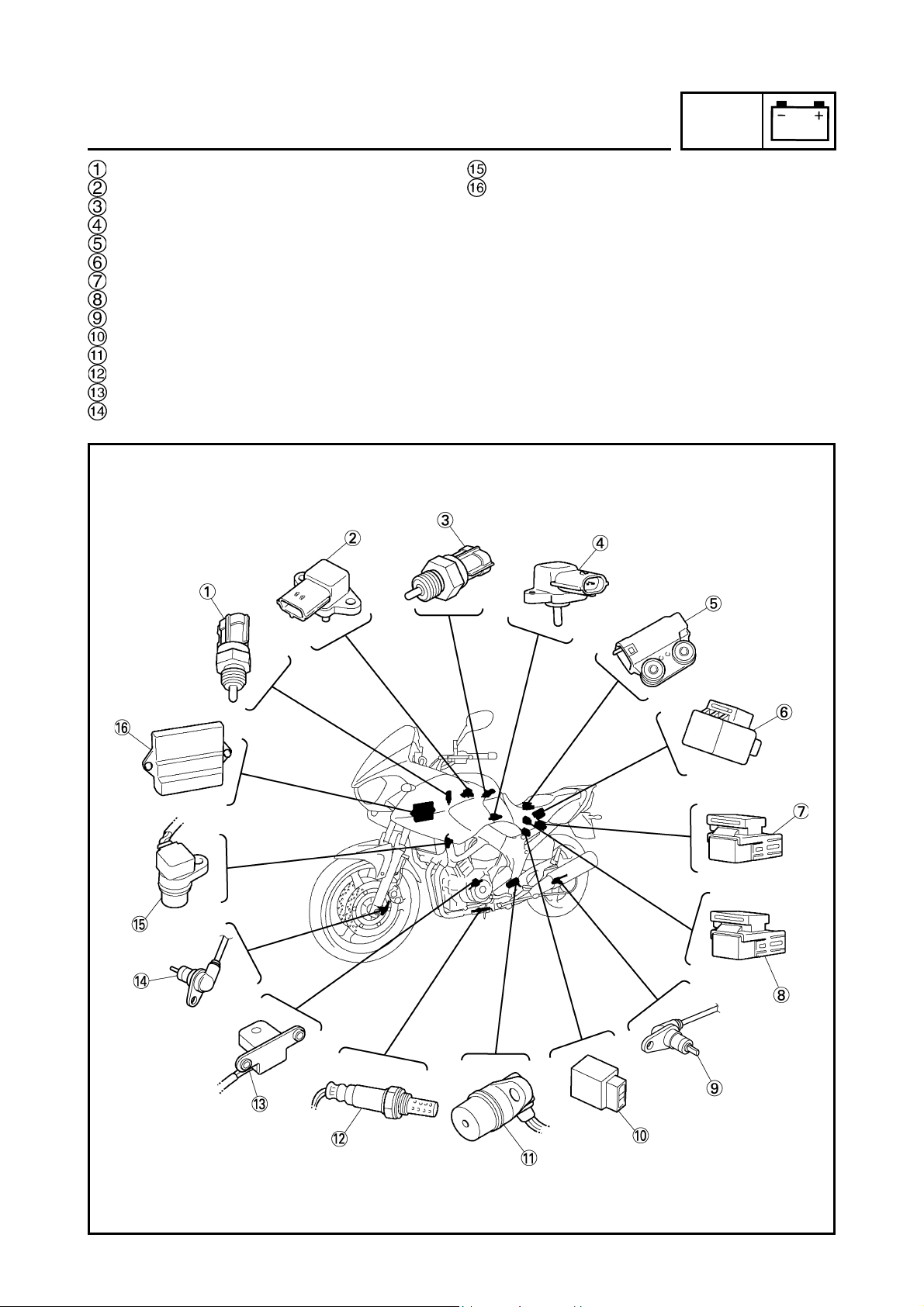
ELECTRICAL COMPONENTS
ELEC
Coolant temperature sensor
Atomospheric pressure sensor
Intake air tempreture sensor
Intake air pressure sensor
Lean angle cut-off switch
Turn signal relay
Fuel injection system relay
Radiator fan motor relay
Rear wheel sensor
Starting circuit cut-off relay
Speed sensor
O
sensor
2
Crankshaft position sensor
Front wheel sensor
Cylinder identification sensor
ECU
75
Page 84

CHECKING THE SWITCHES
EAS00731
ELEC
CHECKING THE SWITCHES
Check each switch for damage or wear, proper connections, and also for continuity between the terminals. Refer to “CHECKING SWITCH CONTINUITY”.
Damage/wear Repair or replace.
Improperly connected Properly connect.
Incorrect continuity reading Replace the switch.
Main switch
Horn switch
Pass switch
Dimmer switch
Hazard switch
Turn signal switch
Clutch switch
Engine stop switch
Start switch
Front brake light switch
76
Neutral switch
Rear brake light switch
Fuses
Sidestand switch
Page 85

ELECTRIC STARTING SYSTEM
EAS00755
ELECTRIC STARTING SYSTEM
CIRCUIT DIAGRAM
R/W
W/B
R/W
W/R
BW
Br/W
P/W
R/WR/W
R/W
A E F HGB
C
D
B
W
W/L
R/W
W/G
W/Y
ABS SUB-WIRE HARNESS 2
W/Y
W/G
W/L
R/W
B
W
WIRE HARNESS
B/W
W/R
BY
W/BP/WL/W
Br/W
ABS SUB-WIRE HARNESS 1
L/W
Br/W
BY
W/BP/W
B/W
WIRE HARNESS
W/R
L
Br
R/W
G/Y
RADIATOR FAN MOTOR
RELAY SUB-WIREHARNESS
G/Y
R/W
L
Br
B/L
Br/B
R/W
Br/W
SUB-WIRE HARNESS 3
Br/W
R/W
B/L
Br/B
WIRE HARNESS WIRE HARNESS
L R/L
G/BR/B
SUB-WIRE HARNESS 1
LR/L
G/BR/B
WIRE HARNESS
P/W
B/L
Y
SUB-WIRE HARNESS 2
Y
B/L
P/W
WIRE HARNESS
Y/L
B/W
W
R/G
HARNESS 1
G/L
W/Y
HEADLIGHT SUB-WIRE
W/Y
G/L
W
R/G
Y/L
B/W
WIRE HARNESS
Ch G L
Br/W
G/R
BY
L/RL/B Dg Lg Br
HEADLIGHT SUB-WIRE HARNESS 2
BY
L/RL/BDgLgBr
G/R
Br/W
ChGL
WIRE HARNESS
W/B
W
W/R
B
P/W
Br/W
39
34
34
33
32
R/B
R/B
O
B/W
GyR
O
G/BR/B
G/Y
Br/B
R/W
L/YB/YL/W
B/WG/WW/B
R/LG/R
P
Y/G
L
LgB/YSbL/Y
R/LW/LR/B
L/G
R/W
L/RL/W
G/R
B/RB/W
L/WBr/R
R/W
R/W
L/W
R/W
R
R
5
Br/W
Br/R
3
Br/L
R
R
4
R
Br/L
W W
GyR
B/W
B/W
Y/B
Br/R
L/R
G/B
R/W
R/L
R/L
R/L
A
B/L
GyY/LY
P/WBr/W
W/Y
Gy/G
R
2
W W
W W
1
R/L
28
27
G/BG/B
A
A
O
GyR
G/BG/B
L/Y
R/L
L/R
R/W
B/Y
L/W
G/W
18
L/Y
G/W
G/W
Gy
L/R
Br/R
14
Lg
R/B
L/W
L/W
13
R
R/G
L/W
R/W
6
8
7
9
R
R
RBWWW
WWW
B
R R
B B
BB
B
Br/R
R
ON
OFF
MAIN
W
W
YB
R/W
W/Y
B/W
B/Y
W/Y
SbB
W/L
W/G
B
W
B/YW/RP/WW/BL/W
W/YB/WW/Y
W/R
Sb
Lg
Br/W
W/R
LgLgSb
W/R
35
Sb B
Lg
R/W
R/W
E
R/W
R/W
Br/R
R/LR/B
Br
30
29
R/L
R/BR/B
R/BR/B
Br/B
Br/R
Br/B
Br/B
E
R/W
R/W
Br/B
Br/R
Br/R
Br/B
26
G/WGyGy
LLYY
B/LB/L
W/B
P
P/W
R/W
Y/G
G/R
Br/W
B
BBA
Y
L
B/L
P/W
L
Y
B/L
L
P/W P/W
19
20
L Y B/L
L
B/L
W/B
B/L
WL/Y
17
R/L
L/G
L/Y
Sb
B/Y
W/L
BB
15
L/G
R/W
12
B
B/W
B/W
BB
B
R/G
B
B/W
B
BBB
B
B
BB
11
R
R
Br/R
Br/L
Br/L
Br/R
Br/L
P
10
ELEC
B
R/W
B/WR/W
40
B/W
W/G
W/L
WW
W/L
RR
WG
W/G
W
B
P/W
W/B
R/W
W/G
W/L
37
Lg
SbB
W/R
B
31
L
B/L
W/Y
Y/B
Y/L
W/Y
G/Y
Gy/G
P
L
B/L
B/L
21
L
P/W
B/L
B/L P L
W/B
B/L
L
L/G B
B
Sb
B
Y/L
B
R/W
G/L
R/G
R/W
R/G
Y/LLg
BB
Y/LG/L
R/W
BB
BB
BB
BB
B
B
Y
L/W
Br/W
B/W
G
B
R/L
36
BR/L
B/WG
W/YL
B/L
B/L
WL/Y
B/L
Gy/G
B/W
B/W
B/W
B/W
Br/W
Br/W
E
Br/W
22
B/L
B/L
E
B/L
B/L
Br/W
B/L
25
WL
Gy/G
B/L
Y/G
L
24
B/L
Y/G
G/R
L
23
B/L
B/L
G/R
16
W/L
FREE
PUSH
58
R/B
R/W
OFF
RUN
57
56
G/Y
R/B
BBr
L/W
R/W
55
R/W
BBr
W/L
G/Y
R/B
R/W
R/Y
76
77
Br/L
Br/L
Br/W
BY
B/W
W/RW/BP/WL/W
38
W/Y
B
W/L
W
R/W
W/G
B/W
B
Y
Br/W
W/R
W/B
P/W
L/W
B/W
W/RW/BP/WL/W
BY
Br/W
B/W
B/W
C
Y/L
Y/L
C
Lg
Lg
D
Lg
Y/L
44
45
Br
43
G
G
D
R/G
R/G
C
Br
Br
D
BrG
54
Br/W
B
BrY Y
G/Y
BrG
78
Br/R
B/Y
W/Y
WB WB
WB
41
42
WWB
W/Y
B/Y
W/YW/L
W/G
R/W
W
B
W/Y
B
W/L
R/W
W/G
B/W
B
Y
Br/W
W/R
W/B
P/W
L/W
W
B
R/W
W/L
W/G
W/Y
W/Y
C
W/Y
B/W
W/Y
4748495051
46
G
R/G
W
W
C
G/L
G/L
C
Br/W
D
Br/W
B/Y
L/Y
L/Y
B/Y
Br/W
Br/W
BrG
L/B
R/Y
Br
60 61 62 63 64
59
R/Y
R/Y
71
Y/BR/Y
R/Y
L/B
L/R
Y
52
R/GBrLgG/LL/R
Br/W
LGG/R
G/R
D
G/R
B/W
W/Y
Y/LW
Y
LL
G/L
G/R
Br/W
D
L
DgYL/B
ChL/YB
Br/W
B/Y
Br
R/Y
B/Y
L/Y
65
Ch
RNL
ON
OFF
YY
HI
LO
B
ON
OFF
B
B/W
ON
OFF
Y/B
L/B
BW
53
BW
B
W W
Dg
B
B
Dg
B
Dg
Br
R/Y
Br/W
B/Y
Dg
D
Dg Y L/B
ChL/Y B
Ch
D
Ch
Y
D
B
66
B/W
L/B
D
YB L/B B
Ch
B
Dg
B
69 70
Ch
B
Ch
Dg
B
B
Dg
Dg Dg
B
Ch
B
B
67 68
Ch
Ch
B
B
L/B L/B
72
BB
B
D
Y
Fuse (main)
Starter relay
YLB
Y L/R B
BB Br Y
73
Br
L/R
L/R L/R
D
Br
79
Br/L
R
BrBrLLB
80
74
Starter motor
L/R
B
Battery
Main switch
B
75
Starting circuit cut-off relay
L/RB
Sidestand switch
Neutral switch
Br Br
F
R/W
F
LL
F
Engine stop switch
R/W R/W
G/YG/Y
81
G/Y
Start switch
L
Br
R/W
Clutch switch
82
G/Y
F
B
L
B
L
Fuse (ignition)
77
Page 86

ELECTRIC STARTING SYSTEM
EAS00756
STARTING CIRCUIT CUT-OFF SYSTEM
OPERATION
If the engine stop switch is set to “ ” and the
main switch is set to “ON” (both switches are
closed), the starter motor can only operate if at
least one of the following conditions is met:
• The transmission is in neutral (the neutral
switch is closed).
• The clutch lever is pulled to the handlebar
(the clutch switch is closed) and the sidestand is up (the sidestand switch is closed).
The starting circuit cut-off relay prevents the
starter motor from operating when neither of
these conditions has been met. In this
instance, the starting circuit cut-off relay is
open so current cannot reach the starter
motor. When at least one of the above conditions has been met the starting circuit cut-off
relay is closed and the engine can be started
by pressing the starter switch.
ELEC
WHEN THE TRANSMISSION IS IN
NEUTRAL
WHEN THE SIDESTAND IS UP AND
THE CLUTCH LEVER IS PULLED
TO THE HANDLEBAR
Battery
Main fuse
Main switch
Ignition fuse
Engine stop switch
Starting circuit cut-off relay
Diode (starting circuit cut-off relay)
Clutch switch
Sidestand switch
Neutral switch
Start switch
Starter relay
Starter motor
78
Page 87

ELECTRIC STARTING SYSTEM
ELEC
EAS00757
TROUBLESHOOTING
The starter motor fails to turn.
Check:
1.main and ignition fuses
2.battery
3.starter motor
4.starting circuit cut-off relay
5.diode (starting circuit cut-off relay)
6.starter relay
7.main switch
8.engine stop switch
9.neutral switch
10.sidestand switch
11.clutch switch
12.start switch
13.wiring connections
(of the entire starting system)
NOTE:NOTE:
• Before troubleshooting, remove the following
part(s):
1) seat
2) fuel tank
3) air filter case
4) side cowlings
• Troubleshoot with the following special
tool(s).
EAS00739
2. Battery
• Check the condition of the battery.
Refer to “CHECKING AND CHARGING
THE BATTERY” in chapter 3. (Manual No.:
5PS1-AE1)
Minimum open-circuit voltage
12.8 V or more at 20°C
• Is the battery OK?
YES
NO
• Clean the battery
terminals.
• Recharge or replace the battery.
EAS00758
3. Starter motor
• Connect the positive battery terminal
and starter motor lead with a jumper
lead .
Pocket tester
90890-03132
EAS00738
1. Main and ignition fuses
• Check the main and ignition fuses for continuity.
Refer to “CHECKING THE FUSES” in chapter 3. (Manual No.: 5PS1-AE1)
• Are the main and ignition fuses OK?
YES
NO
Replace the fuse(s).
WARNINGWARNING
• A wire that is used as a jumper lead
must have at least the same capacity or
more as that of the battery lead, otherwise the jumper lead may burn.
• This check is likely to produce sparks,
therefore make sure nothing flammable
is in the vicinity.
• Does the starter motor turn?
YES
Repair or replace
the starter motor.
NO
79
Page 88

ELECTRIC STARTING SYSTEM
EAS00759
4. Starting circuit cut-off relay
• Disconnect the starting circuit cut-off relay
from the wire harness.
• Connect the pocket tester (Ω × 1) and battery (12 V) to the starting circuit cut-off relay
terminals as shown.
Battery positive terminal →
red/black
Battery negative terminal →
black/ yellow
Tester positive prove → blue/white
Tester negative prove → white/ blue
Tester positive probe →
black/yellow
Tester negative probe →
sky blue
Tester positive probe →
blue/ yellow
Tester negative probe →
sky blue
Tester positive probe →
blue/ yellow
Tester negative probe →
blue/green
Tester positive probe →
sky blue
Tester negative probe →
black/yellow
Tester positive probe →
sky blue
Tester negative probe →
blue/ yellow
ELEC
Continuity
No
continuity
• Does the starting circuit cut-off relay have
continuity between blue/white and black?
YES
NO
Replace the starting
circuit cut-off relay.
EAS00760
5. Starting circuit cut-off relay (diode)
• Disconnect the starting circuit cut-off relay
from the wire harness.
• Connect the pocket tester (Ω × 1) to the
starting circuit cut-off relay terminals as
shown.
• Measure the starting circuit cut-off relay for
continuity as follows.
Tester positive probe →
blue/green
Tester negative probe →
blue/ yellow
NOTE:NOTE:
When you switch the tester’s positive and
negative probes, the readings in the above
chart will be reversed.
• Are the testing readings correct?
YES
NO
80
Replace the starting
circuit cut-off relay.
Page 89

ELECTRIC STARTING SYSTEM
ELEC
EAS00761
6. Starter relay
• Disconnect the starter relay from the coupler.
• Connect the pocket tester (Ω × 1) and battery (12 V) to the starter relay terminals as
shown.
Battery positive terminal →
red/white
Battery negative terminal →
blue/ white
Tester positive probe → red
Tester negative probe → black
EAS00750
8. Engine stop switch
• Check the engine stop switch for continuity.
Refer to “CHECKING THE SWITCHES”.
• Is the engine stop switch OK?
YES
NO
Replace the right
handlebar switch.
EAS00751
9. Neutral switch
• Check the neutral switch for continuity.
Refer to “CHECKING THE SWITCHES”.
• Is the neutral switch OK?
YES
NO
Replace the neutral
switch.
• Does the starter relay have continuity
between red and black?
YES
NO
Replace the starter
relay.
EAS00749
7. Main switch
• Check the main switch for continuity.
Refer to “CHECKING THE SWITCHES”.
• Is the main switch OK?
YES
NO
Replace the main
switch.
EAS00752
10. Sidestand switch
• Check the sidestand switch for continuity.
Refer to “CHECKING THE SWITCHES”.
• Is the sidestand switch OK?
YES
NO
Replace the sidestand switch.
EAS00763
11. Clutch switch
• Check the clutch switch for continuity.
Refer to “CHECKING THE SWITCHES”.
• Is the clutch switch OK?
YES
NO
Replace the clutch
switch.
81
Page 90
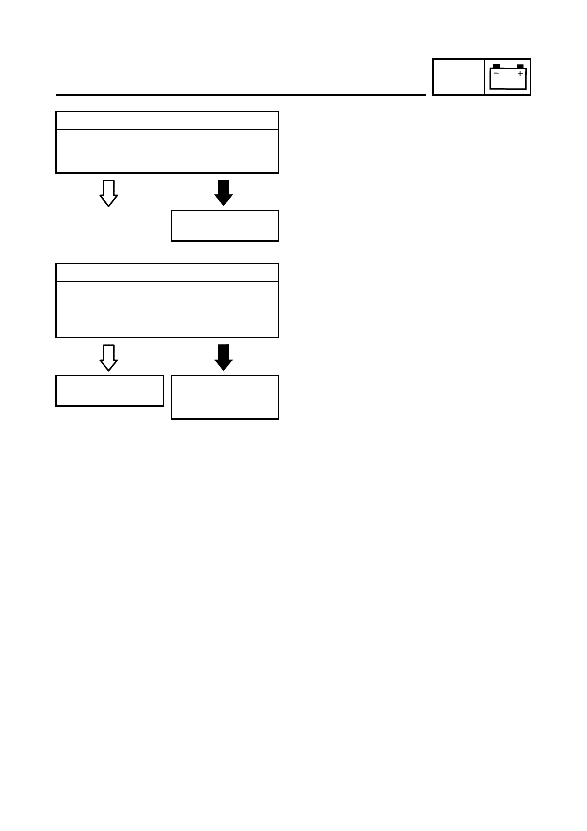
ELECTRIC STARTING SYSTEM
EAS00764
12. Start switch
• Check the start switch for continuity.
Refer to “CHECKING THE SWITCHES”.
• Is the start switch OK?
ELEC
YES
NO
Replace the right
handlebar switch.
EAS00766
13. Wiring
• Check the entire starting system’s wiring.
Refer to “CIRCUIT DIAGRAM”.
• Is the starting system’s wiring properly connected and without defects?
YES
The starting system
circuit is OK.
Properly connect or
repair the starting
NO
system’s wiring.
82
Page 91

EAS00780
SIGNALING SYSTEM
CIRCUIT DIAGRAM
34
32
R/B
O
B/W
B/W
GyR
O
B/W
G/BR/B
Y/B
G/Y
Br/R
Br/B
L/R
R/W
L/YB/YL/W
R/W
B/L
B/WG/WW/B
GyY/LY
R/LG/R
P/WBr/W
P
Y/G
W/Y
L
Gy/G
LgB/YSbL/Y
R/LW/LR/B
L/G
R/W
L/RL/W
G/R
B/RB/W
L/WBr/R
R/W
R/W
L/W
L/W
R/W
6
R/W
7
R
R R
R
R
R
5
R
R
R
R
B
2
RBWWW
W W
W W
W W
1
WWW
A E F HGB
C
D
B
W
W/L
R/W
W/G
W/Y
ABS SUB-WIRE HARNESS 2
W/Y
W/G
W/L
R/W
B
W
WIRE HARNESS
B/W
W/R
BY
W/BP/WL/W
Br/W
ABS SUB-WIRE HARNESS 1
L/W
Br/W
BY
W/BP/W
B/W
WIRE HARNESS
W/R
L
Br
R/W
G/Y
RADIATOR FAN MOTOR
G/Y
R/W
L
Br
B/L
Br/B
R/W
Br/W
SUB-WIRE HARNESS 3
Br/W
R/W
B/L
Br/B
WIRE HARNESS WIRE HARNESS
L R/L
G/BR/B
SUB-WIRE HARNESS 1
LR/L
G/BR/B
WIRE HARNESS
P/W
B/L
Y
SUB-WIRE HARNESS 2
Y
B/L
P/W
WIRE HARNESS
Y/L
B/W
W
R/G
G/L
W/Y
HEADLIGHT SUB-WIRE
W/Y
G/L
W
R/G
Y/L
B/W
WIRE HARNESS
Ch G L
Br/W
G/R
BY
L/RL/B Dg Lg Br
HEADLIGHT SUB-WIRE HARNESS 2
BY
L/RL/BDgLgBr
G/R
Br/W
ChGL
WIRE HARNESS
RELAY SUB-WIREHARNESS
HARNESS 1
3
Br/W
Br/R
4
Br/L
Br/L
Br/R
Lg
R/B
L/W
L/W
R
9
R/W
W/B
R/W
W/R
BW
Br/W
P/W
R/W
W/B
W/R
Br/W
39
R/B
GyR
G/B
R/L
R/L
R/L
A
O
GyR
R/L
L/R
13
B B
R
R/WR/W
W
B
P/W
34
33
R/LR/B
R/L
R/L
28
27
G/BG/B
R/BR/B
A
A
G/BG/B
R/BR/B
L/Y
R/W
B/Y
L/W
G/W
18
L/Y
G/W
G/W
Gy
L/R
R/L
L/G
14
L/Y
Sb
B/Y
W/L
R/W
R/G
8
B
B/W
BB
R
Br/R
P
ON
OFF
MAIN
L/R
Y
R/GBrLgG/LL/R
Br/W
LGG/R
B/W
W/Y
Y/LW
Ch
D
Ch
Y
D
66
L/B
B
Br Br
R/W R/W
G/R
D
G/R
BW
W W
Dg
Dg
D
Dg
Ch
Dg Dg
Ch
L/B L/B
D
Y
YB L/B B
YLB
74
G/Y
L
Br
R/W
ELEC
BW
53
B
Dg
B
B
Dg
B
Ch
B
B
69 70
Ch
B
Dg
B
B
Dg
B
Ch
B
B
67 68
Ch
B
B
72
BB
D
B
LL
F
G/Y
G/YG/Y
F
81
B
82
B
L
B
L
SIGNALING SYSTEM
B
R/W
B/WR/W
40
B/W
W
W/G
W
W/L
WW
W/L
RR
WG
W/G
YB
R/W
W
B
P/W
W/B
W/Y
B/W
B/Y
W/Y
SbB
W/L
W/G
B
W
B/YW/RP/WW/BL/W
W/YB/WW/Y
W/R
Sb
Lg
Br/W
W/R
LgLgSb
SbB
W/R
35
Sb B
Lg
R/W
R/W
E
R/W
R/W
Br/R
Br
30
29
Br/B
Br/R
Br/B
Br/B
E
R/W
R/W
Br/B
Br/R
Br/R
Br/B
Y/B
26
G/WGyGy
LLYY
B/LB/L
W/B
P
P/W
R/W
Y/G
G/R
Br/W
B
BBA
Y
L
B/L
P/W
L
Y
B/L
L
B/L
P/W P/W
19
20
L Y B/L
L
P/W
B/L
L
B/L
W/B
B/L
WL/Y
17
BB
15
L/G
12
B
B/W
BB
Y/LLg
B
R/G
R/W
B
B/W
B
BBB
B
B
BB
11
R
Br/R
Br/L
Br/L
Br/R
Br/L
W/G
R/W
W/L
37
Lg
W/R
B
31
L
B/L
W/Y
Y/L
W/Y
G/Y
Gy/G
P
L
B/L
21
B/L P L
W/B
B/L
L
L/G B
B
Sb
B
Y/L
B
R/W
G/L
R/G
R/W
R/G
BB
Y/LG/L
BB
BB
BB
BB
B
B
Y
L/W
Br/W
B/W
G
B
R/L
36
BR/L
B/WG
W/YL
B/L
B/L
WL/Y
B/L
Gy/G
B/W
B/W
B/W
B/W
Br/W
Br/W
E
Br/W
22
B/L
B/L
E
B/L
B/L
Br/W
B/L
25
WL
Gy/G
B/L
Y/G
L
24
B/L
Y/G
G/R
L
23
B/L
B/L
G/R
16
W/L
FREE
PUSH
58
R/B
R/W
OFF
RUN
57
56
G/Y
R/B
BBr
L/W
R/W
55
R/W
BBr
W/L
G/Y
R/B
R/W
R/Y
76
77
Br/L
Br/L
Br/W
BY
B/W
W/RW/BP/WL/W
38
W/Y
B
W/L
W
R/W
W/G
B/W
B
Y
Br/W
W/R
W/B
P/W
L/W
B/W
W/RW/BP/WL/W
BY
Br/W
B/W
B/W
C
Y/L
Y/L
C
Lg
Lg
D
Lg
Y/L
44
45
Br
43
G
G
D
R/G
R/G
C
Br
Br
D
BrG
54
Br/W
B
BrY Y
G/Y
BrG
78
Br/R
10
B/Y
W/Y
WB WB
WB
41
42
WWB
W/Y
B/Y
W/YW/L
W/G
R/W
W
B
W/Y
B
W/L
R/W
W/G
B/W
B
Y
Br/W
W/R
W/B
P/W
L/W
W
B
R/W
W/L
W/G
W/Y
W/Y
C
W/Y
B/W
W/Y
4748495051
46
G
R/G
W
W
G/L
G/L
C
Br/W
D
Br/W
L/Y
B/Y
Br/W
Br/W
BrG
L/B
R/Y
Br
59
R/Y
R/Y
71
R/Y
Br
79
Br/L
R
52
Y
LL
G/L
G/R
Br/W
D
L
C
Br
DgYL/B
ChL/YB
R/Y
Br/W
B/Y
Br/W
B/Y
Br
R/Y
Dg Y L/B
ChL/Y B
B/Y
L/Y
B/Y
L/Y
65
Ch
RNL
ON
OFF
YY
HI
LO
B
ON
OFF
B
B
B/W
B/W
ON
OFF
60 61 62 63 64
Y/B
L/B
Y/BR/Y
L/B
Y L/R B
BB Br Y
73
Br
L/R
D
80
L/R
L/R L/R
75
L/RB
BrBrLLB
F
R/W
F
83
Page 92

Fuse (main)
Battery
Main switch
Fuse (backup)
Starting circuit cut-off relay
Neutral switch
ECU
Fuel pump
Oil level warning light
Neutral indicator light
Multi-function meter
Engine trouble warning light
Turn signal indicator light
Oil level switch
Turn signal relay
Front brake light switch
Horn switch
Hazard switch
Turn signal switch
Horn
Rear turn signal light (left)
Rear turn signal light (right)
Front turn signal light (left)
Front turn signal light (right)
Rear brake light switch
Tail/brake light
Fuse (hazard)
Fuse (signal)
SIGNALING SYSTEM
ELEC
84
Page 93

SIGNALING SYSTEM
ELEC
EAS00794
TROUBLESHOOTING
• Any of the following fail to light: turn signal light, brake light or an indicator light.
• The horn fails to sound.
Check:
1. main, signaling, hazard light and back up
fuses
2. battery
3. main switch
4. wiring connections
(of the entire signaling system)
NOTE:NOTE:
• Before troubleshooting, remove the following
part(s):
1) fuel tank
2) front cowling
3) air filter case
• Troubleshoot with the following special
tool(s).
Pocket tester
90890-03132
EAS00738
1. Main, signaling system, hazard lighting
and backup fuses
EAS00739
2. Battery
• Check the condition of the battery.
Refer to “CHECKING AND CHARGING
THE BATTERY” in chapter 3. (Manual No.:
5PS1-AE1)
Minimum open-circuit voltage
12.8 V or more at 20°C
• Is the battery OK?
YES
NO
• Clean the battery
terminals.
• Recharge or replace the battery.
EAS00749
3. Main switch
• Check the main switch for continuity.
Refer to “CHECKING THE SWITCHES”.
• Is the main switch OK?
YES
NO
Replace the main
switch.
• Check the main, signaling system, hazard
lighting and backup fuses for continuity.
Refer to “CHECKING THE FUSES” in chapter 3.
• Are the main, signaling system, hazard
lighting and backup fuses OK?
YES
NO
Replace the fuse(s).
EAS00795
4. Wiring
• Check the entire signal system’s wiring.
Refer to “CIRCUIT DIAGRAM”.
• Is the signaling system’s wiring properly
connected and without defects?
YES
Check the condition
of each of the signaling system’s circuits.
Properly connect or
repair the signaling
system’s wiring.
NO
Refer to “CHECKING THE SIGNALING SYSTEM”.
85
Page 94

EAS00796
CHECKING THE SIGNAL SYSTEM
1. The horn fails to sound.
1. Horn switch
• Check the horn switch for continuity.
Refer to “CHECKING THE SWITCHES”.
• Is the horn switch OK?
YES
Replace the left handlebar switch.
2. Voltage
• Connect the pocket tester (DC 20 V) to the
horn connector at the horn terminal as
shown.
NO
SIGNALING SYSTEM
3. Horn
• Disconnect the black connector at the horn
terminal.
• Connect a jumper lead to the horn terminal and ground the jumper lead.
• Set the main switch to “ON”.
• Push the horn switch.
• Does the horn sound?
ELEC
Positive tester probe → black/ white
Negative tester probe → ground
• Set the main switch to “ON”.
• Push the horn switch.
• Measure the voltage (DC 12 V) of black/
white at the horn terminal.
• Is the voltage within specification?
YES
The wiring circuit
from the main switch
to the horn connector is faulty and must
be repaired.
NO
YES
The horn is OK. Replace the horn.
NO
86
Page 95

EAS00797
2. The tail/brake light fails to come on.
SIGNALING SYSTEM
3. Voltage
ELEC
1. Tail/brake light bulb and socket
• Check the tail/ brake light bulb and socket
for continuity.
Refer to “CHECKING THE BULBS AND
BULB SOCKETS” in chapter 3. (Manual
No.: 5PS1-AE1)
• Are the tail/ brake light bulb and socket OK?
YES
Replace the tail/
brake light bulb,
socket or both.
2. Brake light switches
• Check the brake light switches for continuity.
Refer to “CHECKING THE SWITCHES”.
• Is the brake light switch OK?
YES
NO
NO
• Connect the pocket tester (DC 20 V) to the
tail/brake light coupler (wire harness side)
as shown.
Positive tester probe → yellow
Negative tester probe → black
• Set the main switch to “ON”.
• Pull in the brake lever or push down on the
brake pedal.
• Measure the voltage (DC 12 V) of yellow
on the tail/brake light coupler (wire harness
side).
• Is the voltage within specification?
Replace the brake
light switch.
YES
This circuit is OK. The wiring circuit
from the main switch
to the tail/brake light
coupler is faulty and
must be repaired.
NO
87
Page 96

EAS00799
3. The turn signal light, turn signal indicator
light or both fail to blink.
1. Turn signal indicator light bulb and socket
• Check the turn signal light bulb and socket
for continuity.
Refer to “CHECKING THE BULBS AND
BULB SOCKETS” in chapter 3. (Manual
No.: 5PS1-AE1)
• Are the turn signal light bulb and socket
OK?
YES
Replace the turn signal light bulb, socket
or both.
2. Turn signal switch
• Check the turn signal switch for continuity.
Refer to “CHECKING THE SWITCHES”.
• Is the turn signal switch OK?
NO
SIGNALING SYSTEM
• Set the main switch to “ON”.
• Measure the voltage (DC 12 V) on brown/
green at the turn signal relay coupler
(wire harness side).
• Is the voltage within specification?
YES
4. Voltage
• Connect the pocket tester (DC 20 V) to the
turn signal relay coupler (wire harness side)
as shown.
Positive tester probe → brown/ white
Negative tester probe → ground
ELEC
The wiring circuit
from the main switch
to the turn signal
relay coupler is
faulty and must be
repaired.
NO
YES
Replace the left handlebar switch.
3. Voltage
• Connect the pocket tester (DC 20 V) to the
turn signal relay coupler (wire harness side)
as shown.
Positive tester probe → brown/green
Negative tester probe → ground
NO
• Set the main switch to “ON”.
• Set the turn signal switch to “ ” or “ ”.
• Measure the voltage (DC 12 V) on brown/
white at the turn signal relay coupler
(wire harness side).
• Is the voltage within specification?
YES
The turn signal relay
is faulty and must be
replaced.
NO
88
Page 97

5. Voltage
SIGNALING SYSTEM
EAS00800
4. The neutral indicator light fails to come on.
ELEC
• Connect the pocket tester (DC 20 V) to the
turn signal light coupler or meter assembly
coupler (wire harness side) as shown.
Turn signal light
Turn signal indicator light
Left turn signal light
Positive tester probe → chocolate
Negative tester probe → ground
Right turn signal light
Positive tester probe → dark green
Negative tester probe → ground
1. Neutral indicator light bulb and socket
• Check the neutral indicator light bulb and
socket for continuity.
Refer to “CHECKING THE BULBS AND
BULB SOCKETS” in chapter 3. (Manual
No.: 5PS1-AE1)
• Are the neutral indicator light bulb and socket OK?
YES
Replace the neutral
indicator light bulb,
socket or both.
2. Neutral switch
• Check the neutral switch for continuity.
Refer to “CHECKING THE SWITCHES”.
• Is the neutral switch OK?
YES
NO
NO
• Set the main switch to “ON”.
• Set the turn signal switch to “ ” or “ ”.
• Measure the voltage (DC 12 V) of the
brown/white or blue / red at the turn
signal light coupler (wire harness side).
• Is the voltage within specification?
YES
This circuit is OK. The wiring circuit
from the turn signal
switch to the turn
signal light coupler
(meter assembly
coupler) is faulty and
must be repaired.
NO
Replace the neutral
switch.
89
Page 98
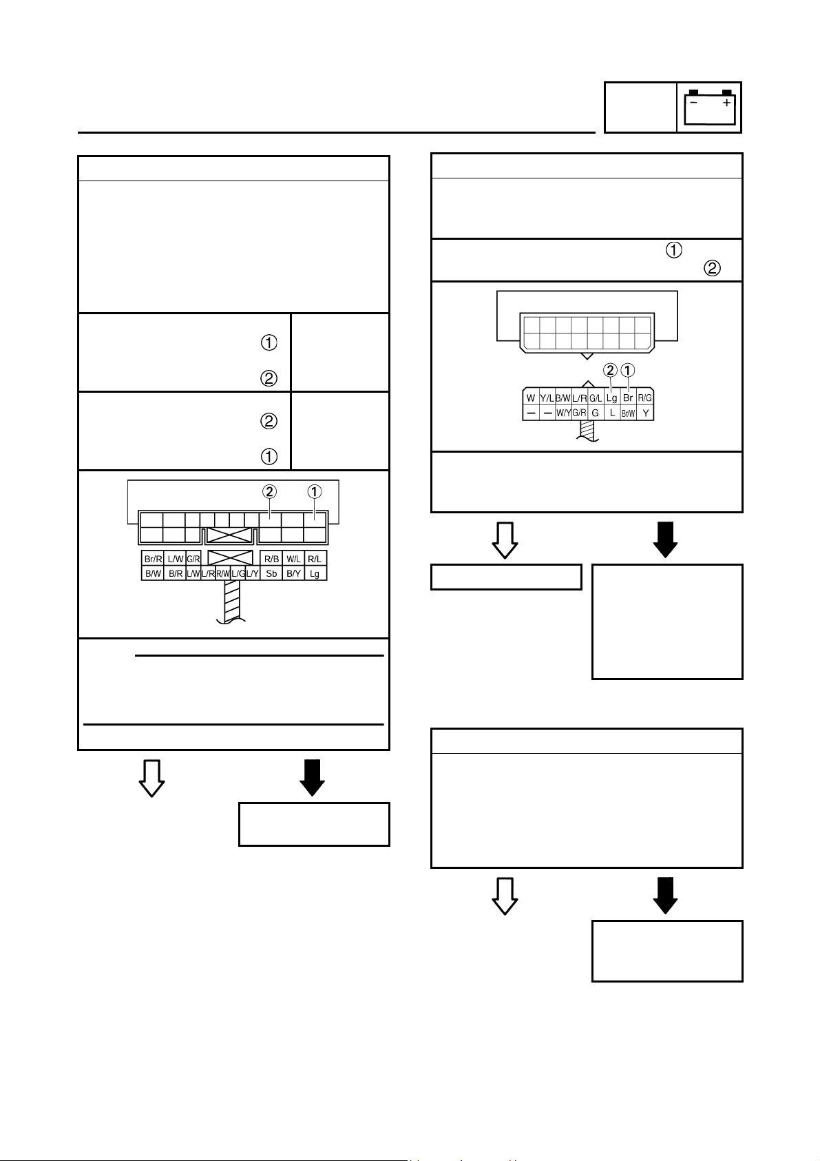
EAS00753
3. Starting circuit cut-off relay (diode)
• Disconnect the starting circuit cut-off relay
from the wire harness.
• Connect the pocket tester (Ω × 1) to the
starting circuit cut-off relay terminals as
shown.
• Check the starting circuit cut-off relay for
continuity.
Tester positive probe →
light green
Tester negative probe →
Continuity
sky blue
Tester positive probe →
sky blue
Tester negative probe →
No
continuity
light green
SIGNALING SYSTEM
ELEC
4. Voltage
• Connect the pocket tester (DC 20 V) to the
meter assembly coupler (wire harness side)
as shown.
Positive tester probe → brown
Negative tester probe → light green
• Set the main switch to “ON”.
• Measure the voltage (DC 12 V).
• Is the voltage within specification?
NOTE:NOTE:
When you switch the positive and negative
tester probes, the readings in the above
chart will be reversed.
• Are the tester readings correct?
YES
NO
Replace the starting
circuit cut-off relay.
YES
NO
This circuit is OK. The wiring circuit
from the main switch
to the meter assembly coupler is faulty
and must be
repaired.
EAS00802
5. The oil level warning light fails to come on.
1. Oil level warning light bulb and socket
• Check the oil level warning light bulb and
socket for continuity.
Refer to “CHECKING THE LEDs” in chapter
8. (Manual No.: 5PS1-AE1)
• Are the oil level warning light bulb and
socket OK?
YES
NO
90
Replace the oil level
warning light bulb,
socket or both.
Page 99

SIGNALING SYSTEM
ELEC
2. Engine oil level switch
• Drain the engine oil and remove the engine
oil level switch from the oil tank.
• Check the engine oil level switch for continuity.
Refer to “CHECKING THE SWITCHES”.
• Is the engine oil level switch OK?
YES
Replace the engine
oil level switch.
3. Voltage
• Connect the pocket tester (DC 20 V) to the
meter assembly coupler (wire harness side)
as shown.
Positive tester probe → brown
Negative tester probe → black/white
NO
4. Voltage
• Connect the pocket tester (DC 20 V) to the
engine oil level switch coupler as shown.
Tester positive probe → white
Tester negative probe → black
• Set the main switch to “ON”.
• Measure the voltage (5 V) of white and
black at the oil level switch coupler.
• Is the voltage within specification?
YES
NO
• Set the main switch to “ON”.
• Measure the voltage (DC 12 V) of brown
and black/ white at the meter assembly
coupler.
• Is the voltage within specification?
YES
The wiring circuit
from the main switch
to the meter assembly coupler is faulty
and must be repaired.
NO
This circuit is OK. The wiring circuit
from the meter
assembly to the oil
level switch coupler
is faulty and must be
repaired.
91
Page 100

EAS00803
6. The fuel level gauge fails to operate.
1. Fuel sender
• Drain the fuel from the fuel tank and remove
the fuel pump assembly from the fuel tank.
• Connect the pocket tester (Ω × 1) to the fuel
sender as shown.
Positive tester probe → green
Negative tester probe → black/white
SIGNALING SYSTEM
• Set the main switch to “ON”.
• Measure the voltage (DC 12 V) of green
and black/white at the meter assembly
coupler.
• Is the voltage within specification?
ELEC
• Measure the fuel sender resistances.
NOTE:NOTE:
Measure the resistances when the float arm
is in contact with the full position and empty
position of the stopper.
Fuel sender resistance
Full position of the float
19 ~ 21 Ω at 20°C
Empty position of the float
139 ~ 141 Ω at 20°C
• Is the fuel sender OK?
YES
Replace the fuel
pump.
NO
YES
The wiring circuit
from the fuel sender
to the meter assembly coupler is faulty
and must be
repaired.
3. Voltage
• Connect the pocket tester (DC 20 V) to the
meter assembly coupler as shown.
Tester positive probe → brown
Tester negative probe → black/ white
NO
2. Voltage
• Connect the pocket tester (DC V 20) to the
meter assembly (wire harness side) as
shown.
Positive tester probe → green
Negative tester probe → black/white
• Set the main switch to “ON”.
• Measure the voltage (12 V) of brown and
black/ white at the meter assembly coupler.
• Is the voltage within specification?
YES
This circuit is OK. Replace the meter
assembly.
92
NO
 Loading...