


Yamaha Star XVS13CB(C), Star, XVS13CB, XVS13CC Owner's Manual
Read this manual carefully before operating this vehicle.
OWNER’S MANUAL
LIT-11626-25-27
XVS13CB(C)
27D-28199-11
DIC183
U27D11E0.book Page 1 Monday, July 11, 2011 11:15 AM
EAU10042
Read this manual carefully before operating this vehicle. This manual should stay with this vehicle if it is sold.
U27D11E0.book Page 1 Monday, July 11, 2011 11:15 AM
INTRODUCTION
Congratulations on your purchase of the Yamaha XVS13CB(C). This model is the result of Yamaha’s vast experience in the
production of fine sporting, touring, and pacesetting racing machines. It represents the high degree of craftsmanship and
reliability that have made Yamaha a leader in these fields.
This manual will give you an understanding of the operation, inspection, and basic maintenance of this motorcycle. If you
have any questions concerning the operation or maintenance of your motorcycle, please consult a Yamaha dealer.
The design and manufacture of this Yamaha motorcycle fully comply with the emissions standards for clean air applicable at
the date of manufacture. Yamaha has met these standards without reducing the performance or economy of operation of the
motorcycle. To maintain these high standards, it is important that you and your Yamaha dealer pay close attention to the
recommended maintenance schedules and operating instructions contained within this manual.
Yamaha continually seeks advancements in product design and quality. Therefore, while this manual contains the most current product information available at the time of printing, there may be minor discrepancies between your motorcycle and this
manual. If there is any question concerning this manual, please consult a Yamaha dealer.
WARNING
Please read this manual and the “YOU AND YOUR MOTORCYCLE: RIDING TIPS” booklet carefully before operating
this motorcycle. Do not attempt to operate this motorcycle until you have attained adequate knowledge of its controls and operating features. Regular inspections and careful maintenance, along with good operating techniques,
will help ensure that you safely enjoy the capabilities and reliability of this motorcycle.
EAU10083
EWA10011
U27D11E0.book Page 1 Monday, July 11, 2011 11:15 AM
IMPORTANT MANUAL INFORMATION
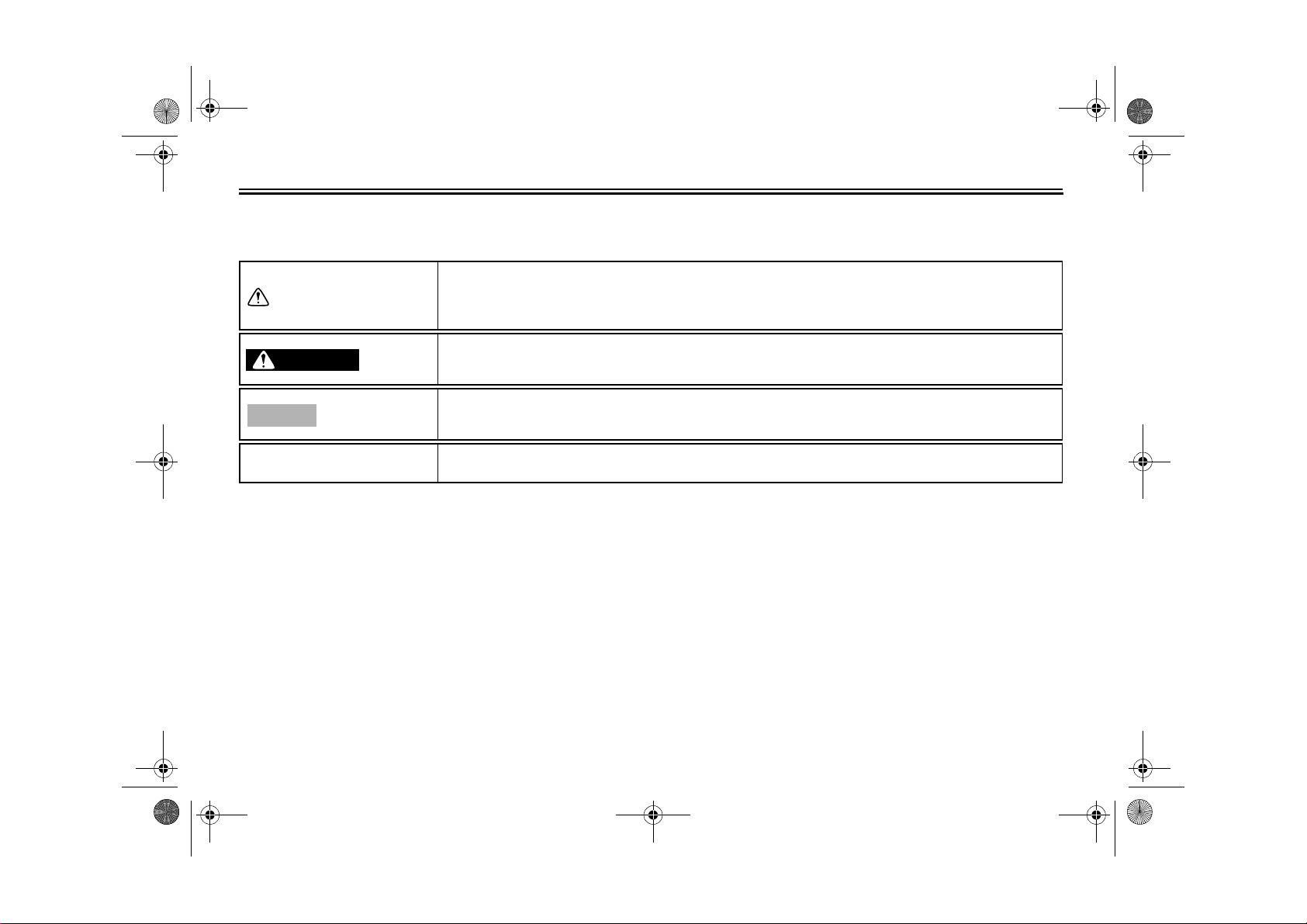
Particularly important information is distinguished in this manual by the following notations:
This is the safety alert symbol. It is used to alert you to potential personal injury
hazards. Obey all safety messages that follow this symbol to avoid possible injury
or death.
EAU10133
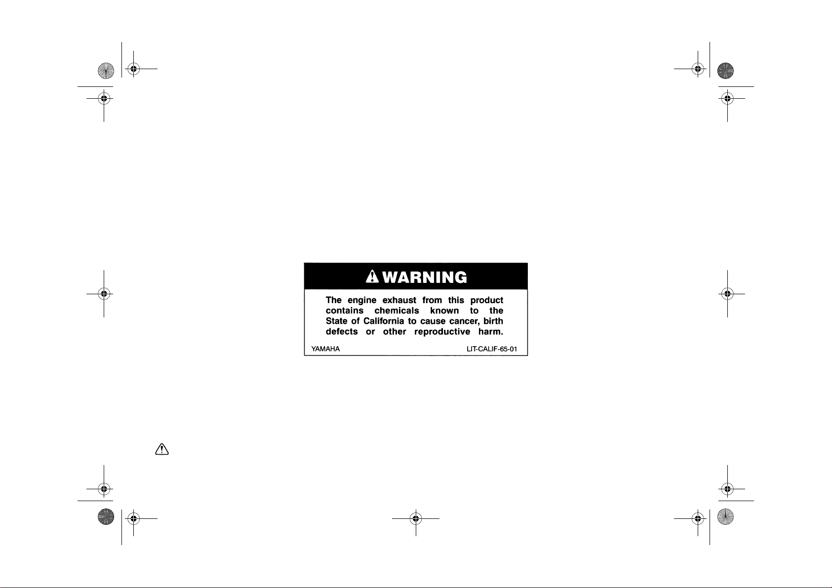
WARNING
NOTICE
TIP
A WARNING indicates a hazardous situation which, if not avoided, could result in
death or serious injury.
A NOTICE indicates special precautions that must be taken to avoid damage to the
vehicle or other property.
A TIP provides key information to make procedures easier or clearer.
*Product and specifications are subject to change without notice.
U27D11E0.book Page 2 Monday, July 11, 2011 11:15 AM
IMPORTANT MANUAL INFORMATION
EAU10193
XVS13CB(C)
OWNER’S MANUAL
©2011 by Yamaha Motor Corporation, U.S.A.
1st edition, June 2011
All rights reserved.
Any reprinting or unauthorized use
without the written permission of
Yamaha Motor Corporation, U.S.A.
is expressly prohibited.
Printed in Japan.
P/N LIT-11626-25-27
U27D11E0.book Page 1 Monday, July 11, 2011 11:15 AM
TABLE OF CONTENTS
LOCATION OF IMPORTANT
LABELS .............................................1-1
SAFETY INFORMATION ..................2-1
DESCRIPTION ..................................3-1
Left view ..........................................3-1
Right view........................................3-2
Controls and instruments.................3-3
INSTRUMENT AND CONTROL
FUNCTIONS .......................................4-1
Main switch/steering lock ................4-1
Indicator lights and warning
lights ............................................4-2
Multi-function meter unit .................4-4
Handlebar switches ........................4-7
Clutch lever .....................................4-8
Shift pedal .......................................4-9
Brake lever .....................................4-9
Brake pedal ....................................4-9
Fuel tank cap ................................4-10
Fuel ...............................................4-10
Fuel tank breather/overflow
hose ..........................................4-12
Catalytic converter ........................4-12
Seat ..............................................4-13
Helmet holder ...............................4-14
Adjusting the shock absorber
assembly ...................................4-14
Sidestand ......................................4-15
Ignition circuit cut-off system ........ 4-16
FOR YOUR SAFETY –
PRE-OPERATION CHECKS .............5-1
OPERATION AND IMPORTANT
RIDING POINTS.................................6-1
Starting the engine .........................6-1
Shifting ...........................................6-2
Engine break-in ..............................6-3
Parking ...........................................6-4
PERIODIC MAINTENANCE AND
ADJUSTMENT ................................... 7-1
Owner’s tool kit ...............................7-2
Periodic maintenance chart for the
emission control system ............. 7-3
General maintenance and
lubrication chart ..........................7-5
Removing and installing the
panel ...........................................7-9
Checking the spark plugs ............... 7-9
Canister (for California only) ........ 7-11
Engine oil and oil filter cartridge ... 7-11
Coolant .........................................7-14
Replacing the air filter element ..... 7-15
Checking the throttle grip free
play ...........................................7-16
Valve clearance ............................7-16
Tires .............................................7-17
Cast wheels .................................. 7-18
Adjusting the clutch lever free
play ........................................... 7-19
Checking the brake lever free
play ........................................... 7-20
Brake light switches ..................... 7-20
Checking the front and rear brake
pads .......................................... 7-21
Checking the brake fluid level ...... 7-21
Changing the brake fluid .............. 7-23
Drive belt slack ............................ 7-23
Checking and lubricating the
cables ....................................... 7-24
Checking and lubricating the
throttle grip and cable ............... 7-24
Checking and lubricating the
brake and shift pedals .............. 7-25
Checking and lubricating the
brake and clutch levers ............ 7-25
Checking and lubricating the
sidestand .................................. 7-26
Lubricating the swingarm
pivots ........................................ 7-26
Lubricating the rear suspension ... 7-27
Checking the front fork ................. 7-27
Checking the steering .................. 7-28
Checking the wheel bearings ....... 7-28
Battery ......................................... 7-28
Replacing the fuses ..................... 7-30
Replacing the headlight bulb ....... 7-31
Tail/brake light ............................. 7-32
U27D11E0.book Page 2 Monday, July 11, 2011 11:15 AM
Replacing a turn signal light
bulb ...........................................7-33
License plate light .........................7-33
Supporting the motorcycle ............7-34
Troubleshooting ............................7-34
Troubleshooting charts .................7-36
MOTORCYCLE CARE AND
STORAGE ..........................................8-1
Matte color caution .........................8-1
Care ................................................8-1
Storage ...........................................8-3
SPECIFICATIONS .............................9-1
CONSUMER INFORMATION...........10-1
Identification numbers ..................10-1
Reporting safety defects ...............10-3
Motorcycle noise regulation ..........10-4
Maintenance record ......................10-5
YAMAHA MOTOR
CORPORATION, U.S.A.
STREET AND ENDURO
MOTORCYCLE LIMITED
WARRANTY .............................10-7
YAMAHA EXTENDED SERVICE
(Y.E.S.) .....................................10-9
TABLE OF CONTENTS
U27D11E0.book Page 1 Monday, July 11, 2011 11:15 AM
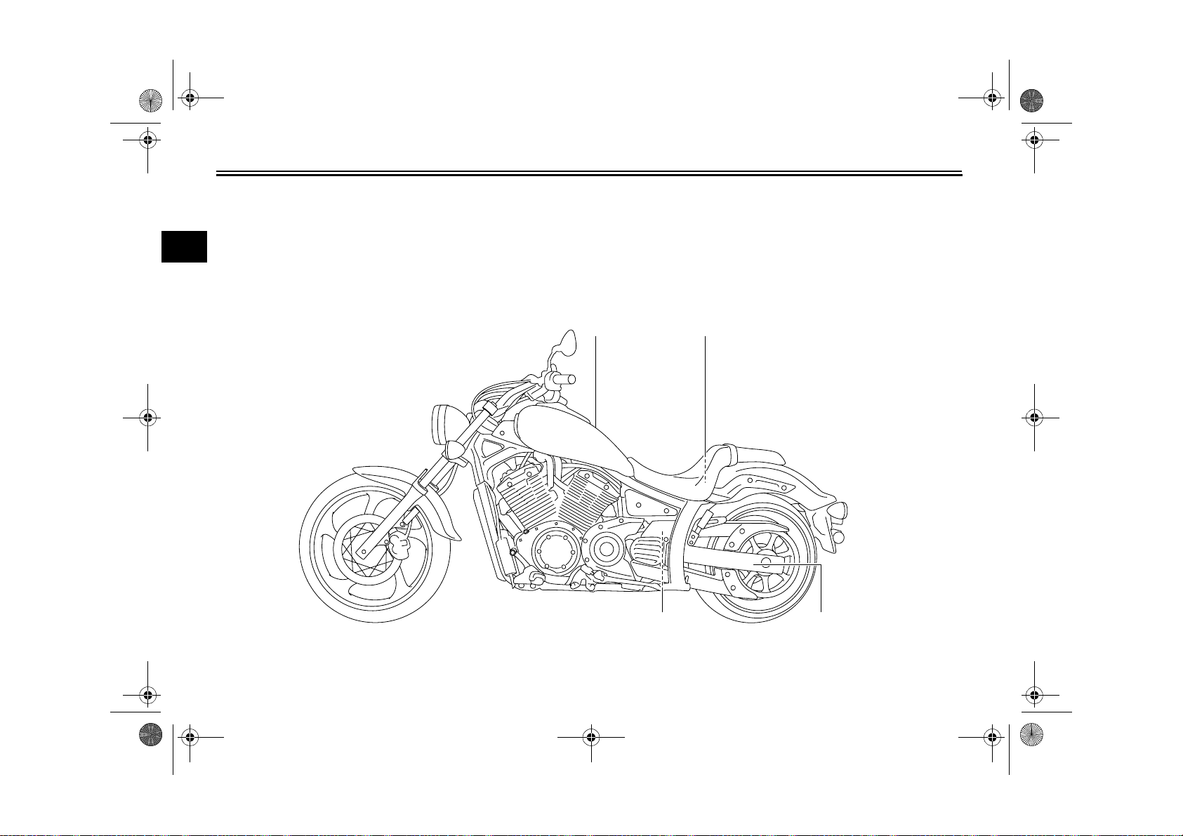
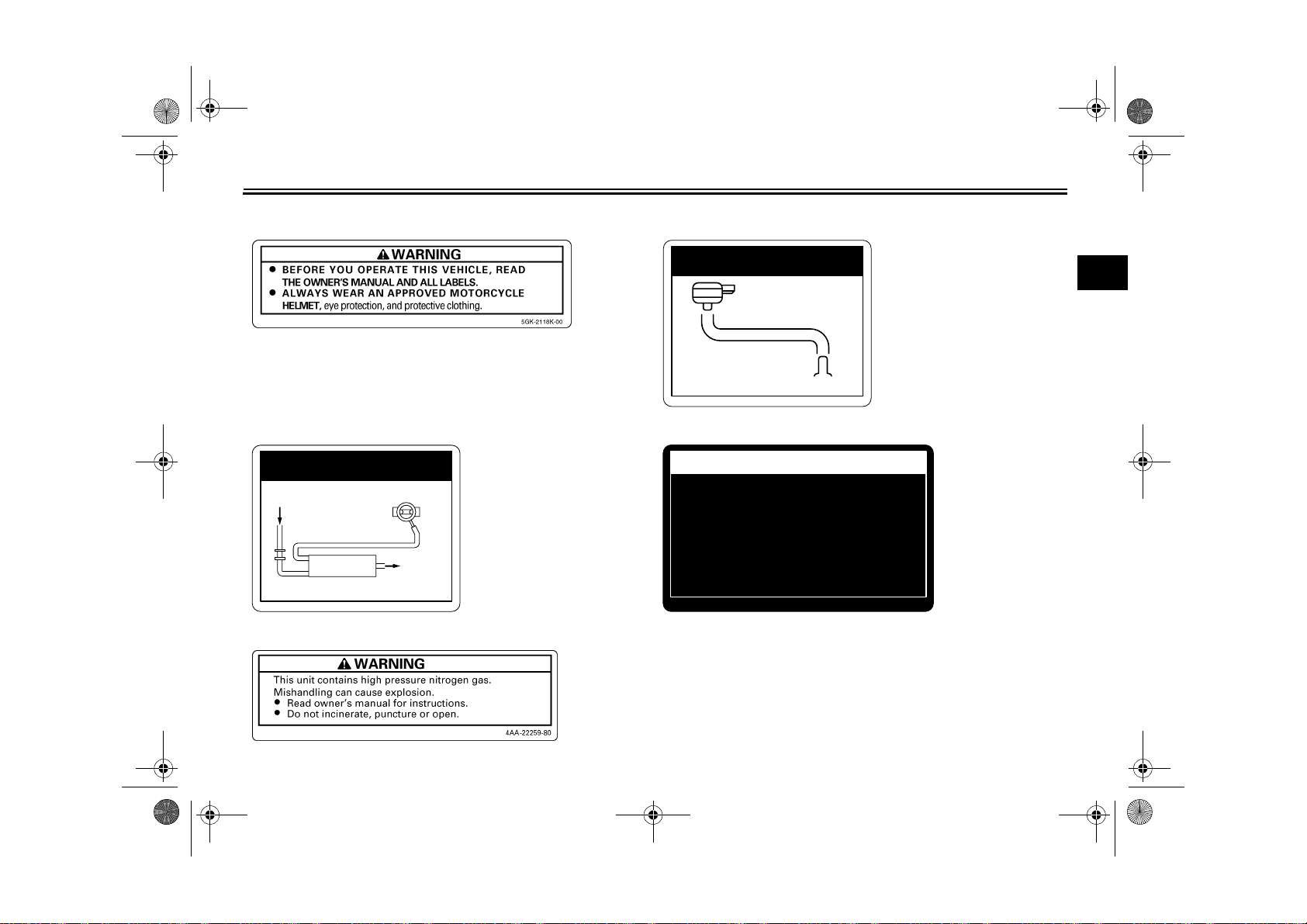
LOCATION OF IMPORTANT LABELS
Read and understand all of the labels on your vehicle. They contain important information for safe and proper operation of
your vehicle. Never remove any labels from your vehicle. If a label becomes difficult to read or comes off, a replacement label
1
is available from your Yamaha dealer.
1 2,3
EAU10384
1-1
5 4
U27D11E0.book Page 2 Monday, July 11, 2011 11:15 AM
LOCATION OF IMPORTANT LABELS
1 2 California only
3 California only
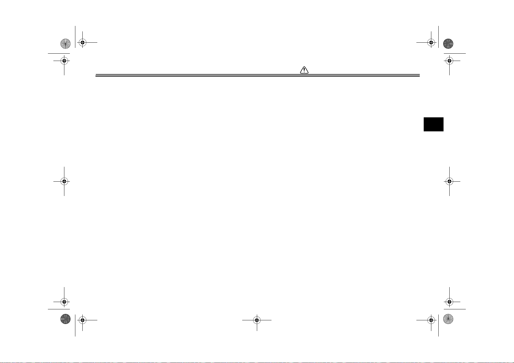
EMISSION HOSE ROUTING
FUEL TANK
THROTTLE BODY
ATMOSPHERE
CANISTER
5RU-21686-00
5
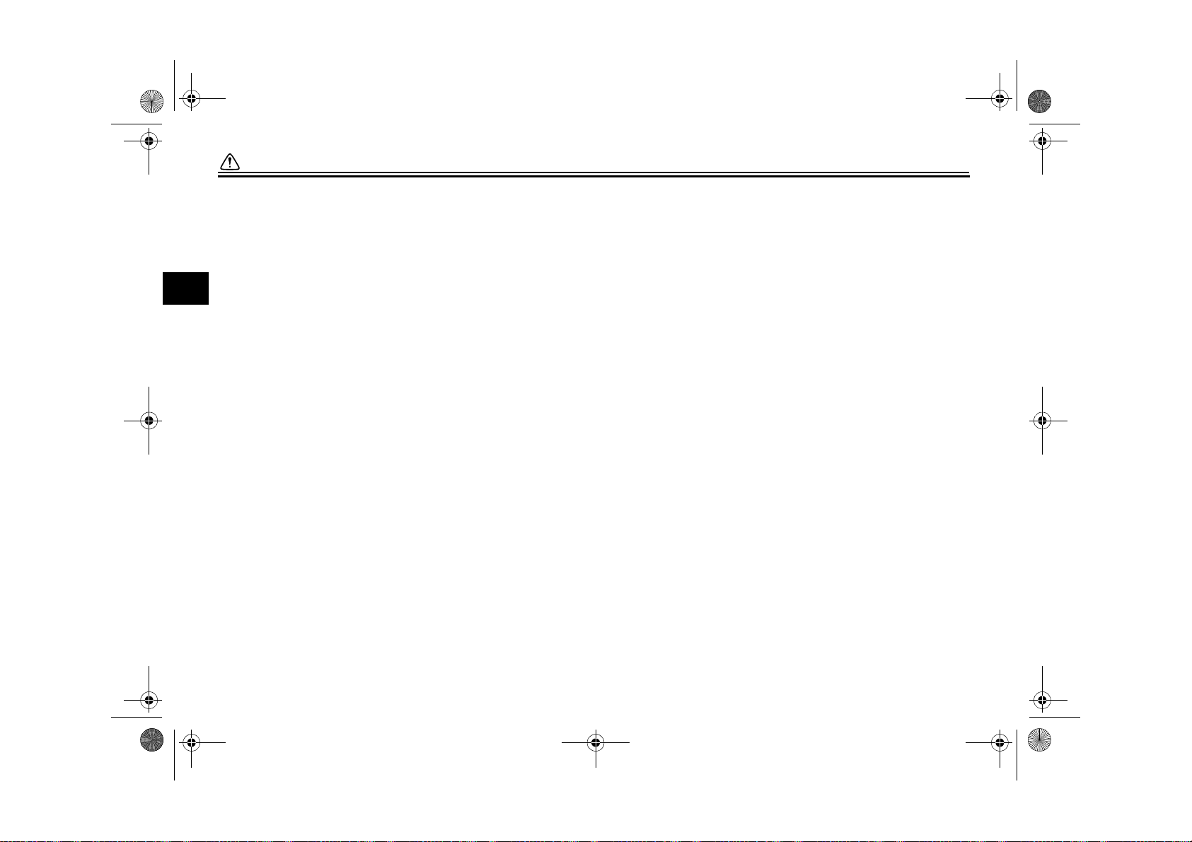
VACUUM HOSE ROUTING
PRESS. SENSOR
INTAKE MANIFOLD
34B-21684-00
4
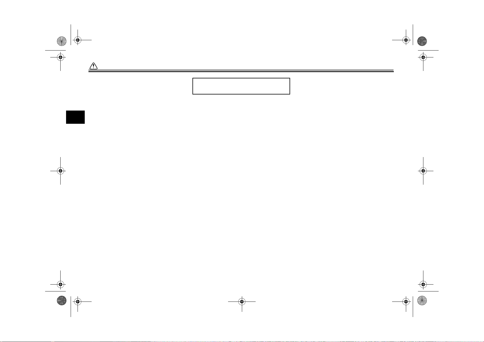
TIRE INFORMATION
Cold tire normal pressure should be set
as follows.
• Up to 90 kg (198 lbs) load
FRONT
REAR
FRONT
REAR
: 250 kPa, (2.50 kgf/cm²), 36 psi
: 280 kPa, (2.80 kgf/cm²), 41 psi
• 90kg (198 lbs) ~ maximum load
: 250 kPa, (2.50 kgf/cm²), 36 psi
: 280 kPa, (2.80 kgf/cm²), 41 psi
1
27D-21668-00
1-2
U27D11E0.book Page 1 Monday, July 11, 2011 11:15 AM
SAFETY INFORMATION
Be a Responsible Owner
As the vehicle’s owner, you are respon-
sible for the safe and proper operation
2
of your motorcycle.
Motorcycles are single-track vehicles.
Their safe use and operation are dependent upon the use of proper riding
techniques as well as the expertise of
the operator. Every operator should
know the following requirements before
riding this motorcycle.
He or she should:
● Obtain thorough instructions from
a competent source on all aspects
of motorcycle operation.
● Observe the warnings and mainte-
nance requirements in this Owner’s Manual.
● Obtain qualified training in safe
and proper riding techniques.
● Obtain professional technical ser-
vice as indicated in this Owner’s
Manual and/or when made necessary by mechanical conditions.
EAU10289
Safe Riding
Perform the pre-operation checks each
time you use the vehicle to make sure it
is in safe operating condition. Failure to
inspect or maintain the vehicle properly
increases the possibility of an accident
or equipment damage. See page 5-1
for a list of pre-operation checks.
● This motorcycle is designed to car-
ry the operator and a passenger.
● The failure of motorists to detect
and recognize motorcycles in traffic is the predominating cause of
automobile/motorcycle accidents.
Many accidents have been caused
by an automobile driver who did
not see the motorcycle. Making
yourself conspicuous appears to
be very effective in reducing the
chance of this type of accident.
Therefore:
• Wear a brightly colored jacket.
• Use extra caution when you are
approaching and passing
through intersections, since intersections are the most likely
places for motorcycle accidents
to occur.
• Ride where other motorists can
see you. Avoid riding in another
motorist’s blind spot.
● Many accidents involve inexperi-
enced operators. In fact, many operators who have been involved in
accidents do not even have a current motorcycle license.
• Make sure that you are qualified
and that you only lend your motorcycle to other qualified operators.
• Know your skills and limits.
Staying within your limits may
help you to avoid an accident.
• We recommend that you practice riding your motorcycle
where there is no traffic until you
have become thoroughly familiar with the motorcycle and all of
its controls.
● Many accidents have been caused
by error of the motorcycle operator. A typical error made by the operator is veering wide on a turn
2-1
U27D11E0.book Page 2 Monday, July 11, 2011 11:15 AM
SAFETY INFORMATION
due to excessive speed or undercornering (insufficient lean angle
for the speed).
• Always obey the speed limit and
never travel faster than warranted by road and traffic conditions.
• Always signal before turning or
changing lanes. Make sure that
other motorists can see you.
● The posture of the operator and
passenger is important for proper
control.
• The operator should keep both
hands on the handlebar and
both feet on the operator footrests during operation to maintain control of the motorcycle.
• The passenger should always
hold onto the operator, the seat
strap or grab bar, if equipped,
with both hands and keep both
feet on the passenger footrests.
Never carry a passenger unless
he or she can firmly place both
feet on the passenger footrests.
● Never ride under the influence of
alcohol or other drugs.
● This motorcycle is designed for on-
road use only. It is not suitable for
off-road use.
Protective Apparel
The majority of fatalities from motorcycle accidents are the result of head injuries. The use of a safety helmet is the
single most critical factor in the prevention or reduction of head injuries.
● Always wear an approved helmet.
● Wear a face shield or goggles.
Wind in your unprotected eyes
could contribute to an impairment
of vision that could delay seeing a
hazard.
● The use of a jacket, heavy boots,
trousers, gloves, etc., is effective in
preventing or reducing abrasions
or lacerations.
● Never wear loose-fitting clothes,
otherwise they could catch on the
control levers, footrests, or wheels
and cause injury or an accident.
● Always wear protective clothing
that covers your legs, ankles, and
feet. The engine or exhaust system become very hot during or after operation and can cause burns.
2-2
● A passenger should also observe
the above precautions.
Avoid Carbon Monoxide Poisoning
All engine exhaust contains carbon
monoxide, a deadly gas. Breathing carbon monoxide can cause headaches,
dizziness, drowsiness, nausea, confusion, and eventually death.
Carbon Monoxide is a colorless, odorless, tasteless gas which may be
present even if you do not see or smell
any engine exhaust. Deadly levels of
carbon monoxide can collect rapidly
and you can quickly be overcome and
unable to save yourself. Also, deadly
levels of carbon monoxide can linger
for hours or days in enclosed or poorly
ventilated areas. If you experience any
symptoms of carbon monoxide poisoning, leave the area immediately, get
fresh air, and SEEK MEDICAL TREATMENT.
● Do not run engine indoors. Even if
you try to ventilate engine exhaust
with fans or open windows and
doors, carbon monoxide can rapidly reach dangerous levels.
2
U27D11E0.book Page 3 Monday, July 11, 2011 11:15 AM
SAFETY INFORMATION
● Do not run engine in poorly venti-
lated or partially enclosed areas
such as barns, garages, or carports.
● Do not run engine outdoors where
2
engine exhaust can be drawn into
a building through openings such
as windows and doors.
Loading
Adding accessories or cargo to your
motorcycle can adversely affect stability and handling if the weight distribution
of the motorcycle is changed. To avoid
the possibility of an accident, use extreme caution when adding cargo or
accessories to your motorcycle. Use
extra care when riding a motorcycle
that has added cargo or accessories.
Here, along with the information about
accessories below, are some general
guidelines to follow if loading cargo to
your motorcycle:
The total weight of the operator, passenger, accessories and cargo must
not exceed the maximum load limit.
Operation of an overloaded vehicle
could cause an accident.
Maximum load:
204 kg (450 lb)
When loading within this weight limit,
keep the following in mind:
● Cargo and accessory weight
should be kept as low and close to
the motorcycle as possible. Securely pack your heaviest items as
close to the center of the vehicle as
possible and make sure to distribute the weight as evenly as possible on both sides of the motorcycle
to minimize imbalance or instability.
● Shifting weights can create a sud-
den imbalance. Make sure that accessories and cargo are securely
attached to the motorcycle before
riding. Check accessory mounts
and cargo restraints frequently.
• Properly adjust the suspension
for your load (suspension-adjustable models only), and
check the condition and pressure of your tires.
• Never attach any large or heavy
items to the handlebar, front
fork, or front fender. These
2-3
items, including such cargo as
sleeping bags, duffel bags, or
tents, can create unstable handling or a slow steering response.
● This vehicle is not designed to
pull a trailer or to be attached to
a sidecar.
Genuine Yamaha Accessories
Choosing accessories for your vehicle
is an important decision. Genuine
Yamaha accessories, which are available only from a Yamaha dealer, have
been designed, tested, and approved
by Yamaha for use on your vehicle.
Many companies with no connection to
Yamaha manufacture parts and accessories or offer other modifications for
Yamaha vehicles. Yamaha is not in a
position to test the products that these
aftermarket companies produce.
Therefore, Yamaha can neither endorse nor recommend the use of accessories not sold by Yamaha or
modifications not specifically recommended by Yamaha, even if sold and
installed by a Yamaha dealer.

U27D11E0.book Page 4 Monday, July 11, 2011 11:15 AM
SAFETY INFORMATION
Aftermarket Parts, Accessories, and
Modifications
While you may find aftermarket products similar in design and quality to
genuine Yamaha accessories, recognize that some aftermarket accessories
or modifications are not suitable because of potential safety hazards to you
or others. Installing aftermarket products or having other modifications performed to your vehicle that change any
of the vehicle’s design or operation
characteristics can put you and others
at greater risk of serious injury or death.
You are responsible for injuries related
to changes in the vehicle.
Keep the following guidelines in mind,
as well as those provided under “Load-
ing” when mounting accessories.
● Never install accessories or carry
cargo that would impair the performance of your motorcycle. Carefully inspect the accessory before
using it to make sure that it does
not in any way reduce ground
clearance or cornering clearance,
limit suspension travel, steering
travel or control operation, or obscure lights or reflectors.
• Accessories fitted to the handlebar or the front fork area can
create instability due to improper
weight distribution or aerodynamic changes. If accessories
are added to the handlebar or
front fork area, they must be as
lightweight as possible and
should be kept to a minimum.
• Bulky or large accessories may
seriously affect the stability of
the motorcycle due to aerodynamic effects. Wind may attempt to lift the motorcycle, or
the motorcycle may become unstable in cross winds. These accessories may also cause
instability when passing or being
passed by large vehicles.
• Certain accessories can displace the operator from his or
her normal riding position. This
improper position limits the freedom of movement of the opera-
tor and may limit control ability,
therefore, such accessories are
not recommended.
● Use caution when adding electri-
cal accessories. If electrical accessories exceed the capacity of the
motorcycle’s electrical system, an
electric failure could result, which
could cause a dangerous loss of
lights or engine power.
Aftermarket Tires and Rims
The tires and rims that came with your
motorcycle were designed to match the
performance capabilities and to provide
the best combination of handling, braking, and comfort. Other tires, rims, sizes, and combinations may not be
appropriate. Refer to page 7-17 for tire
specifications and more information on
replacing your tires.
Transporting the Motorcycle
Be sure to observe following instructions before transporting the motorcycle in another vehicle.
● Remove all loose items from the
motorcycle.
2
2-4
U27D11E0.book Page 5 Monday, July 11, 2011 11:15 AM
SAFETY INFORMATION
● Check that the fuel cock (if
equipped) is in the “OFF” position
and that there are no fuel leaks.
● Point the front wheel straight
ahead on the trailer or in the truck
2
bed, and choke it in a rail to prevent movement.
● Shift the transmission in gear (for
models with a manual transmission).
● Secure the motorcycle with tie-
downs or suitable straps that are
attached to solid parts of the motorcycle, such as the frame or upper front fork triple clamp (and not,
for example, to rubber-mounted
handlebars or turn signals, or parts
that could break). Choose the location for the straps carefully so
the straps will not rub against
painted surfaces during transport.
● The suspension should be com-
pressed somewhat by the tiedowns, if possible, so that the motorcycle will not bounce excessively during transport.
2-5
U27D11E0.book Page 1 Monday, July 11, 2011 11:15 AM
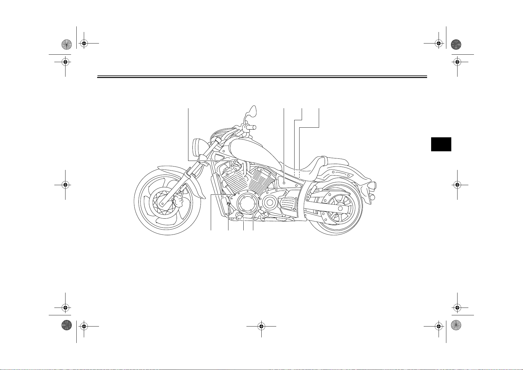
Left view
DESCRIPTION
EAU10410
2 3,4,5 61
3
1. Spark plug (page 7-9)
2. Seat lock (page 4-13)
3. Fuel injection system fuse (page 7-30)
4. Fuse box (page 7-30)
5. Main fuse (page 7-30)
6. Helmet holder (page 4-14)
7. Engine oil level check window (page 7-11)
8. Engine oil drain bolt (page 7-11)
910 78
9. Shift pedal (page 4-9)
10.Engine oil filler cap (page 7-11)
3-1
U27D11E0.book Page 2 Monday, July 11, 2011 11:15 AM
DESCRIPTION
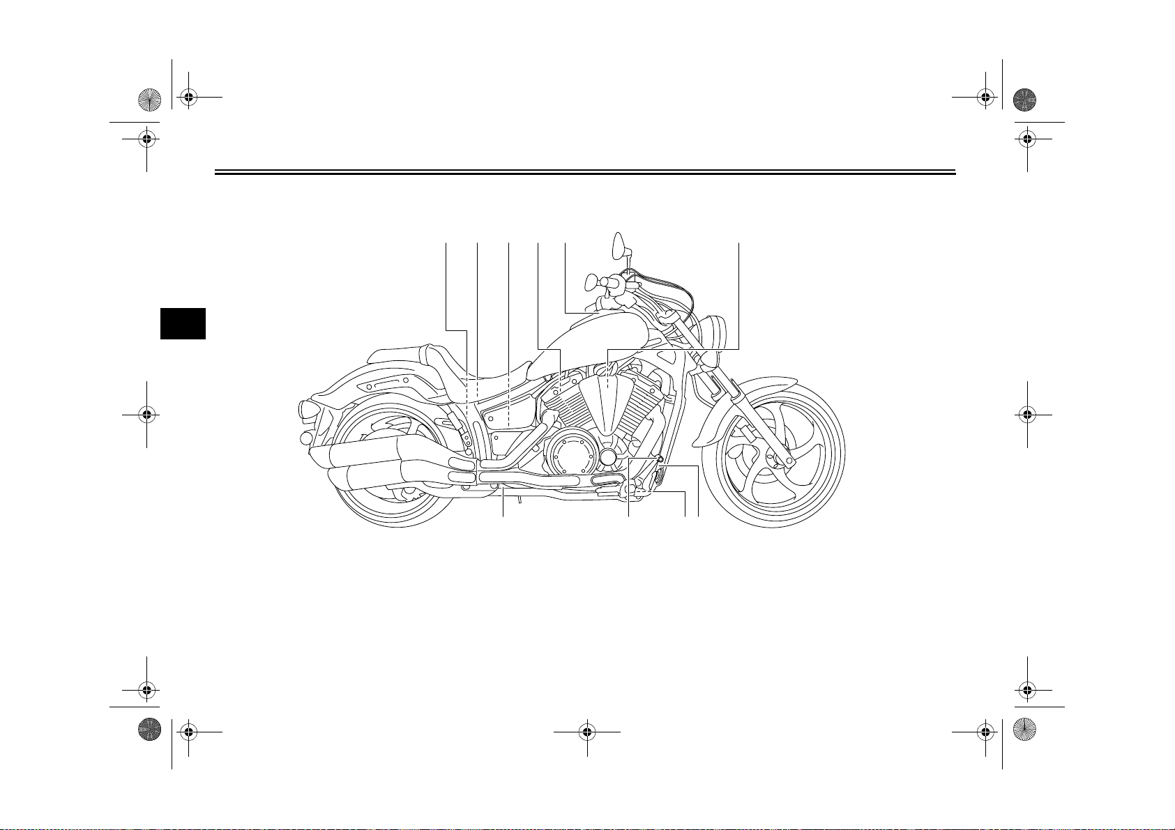
Right view
3
EAU10420
2,3 4 6 751
11 910 8
1. Rear brake fluid reservoir (page 7-21)
2. Owner’s tool kit (page 7-2)
3. Battery (page 7-28)
4. Shock absorber assembly spring preload adjusting ring (page 4-14)
5. Spark plug (page 7-9)
6. Fuel tank cap (page 4-10)
7. Air filter element (page 7-15)
8. Rear brake light switch (page 7-20)
9. Engine oil filter cartridge (page 7-11)
10.Brake pedal (page 4-9)
11.Coolant reservoir (page 7-14)
3-2
U27D11E0.book Page 3 Monday, July 11, 2011 11:15 AM
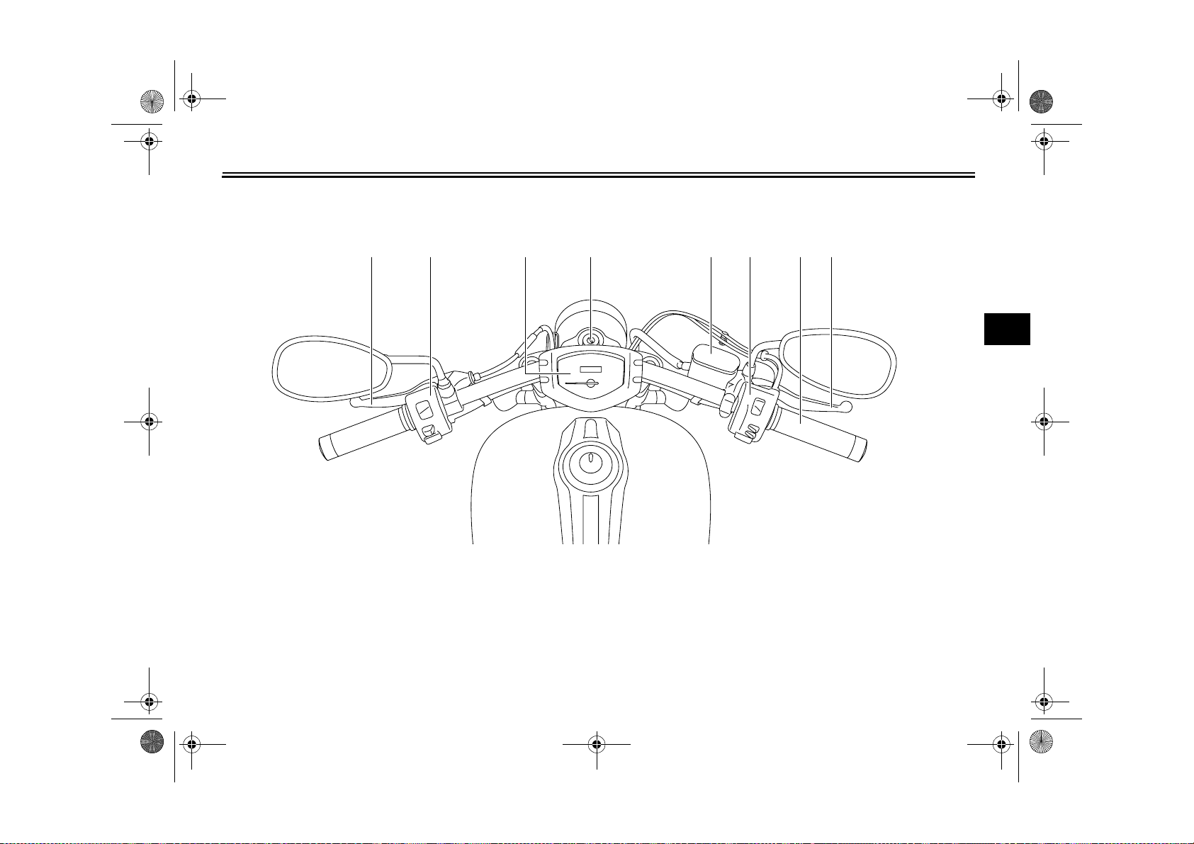
Controls and instruments
1 2 3 4 65 87
DESCRIPTION
EAU10430
3
1. Clutch lever (page 4-8)
2. Left handlebar switches (page 4-7)
3. Multi-function meter unit (page 4-4)
4. Main switch/steering lock (page 4-1)
5. Front brake fluid reservoir (page 7-21)
6. Right handlebar switches (page 4-7)
7. Throttle grip (page 7-16)
8. Brake lever (page 4-9)
3-3
U27D11E0.book Page 1 Monday, July 11, 2011 11:15 AM
INSTRUMENT AND CONTROL FUNCTIONS
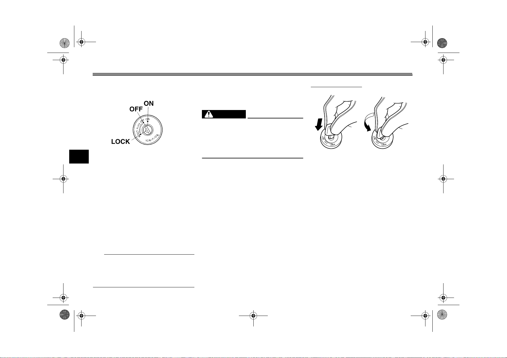
Main switch/steering lock
4
The main switch/steering lock controls
the ignition and lighting systems, and is
used to lock the steering. The various
positions are described below.
ON
All electrical circuits are supplied with
power, and the meter lighting, taillight,
license plate lights and position lights
come on, and the engine can be started. The key cannot be removed.
TIP
The headlight comes on automatically
when the engine is started and stays on
until the key is turned to “OFF”, even if
the engine stalls.
EAU10460
EAU48360
OFF
EAU10661
All electrical systems are off. The key
can be removed.
EWA10061
WARNING
Never turn the key to “OFF” or
“LOCK” while the vehicle is moving.
Otherwise the electrical systems will
be switched off, which may result in
loss of control or an accident.
EAU10683
LOCK
The steering is locked, and all electrical
systems are off. The key can be removed.
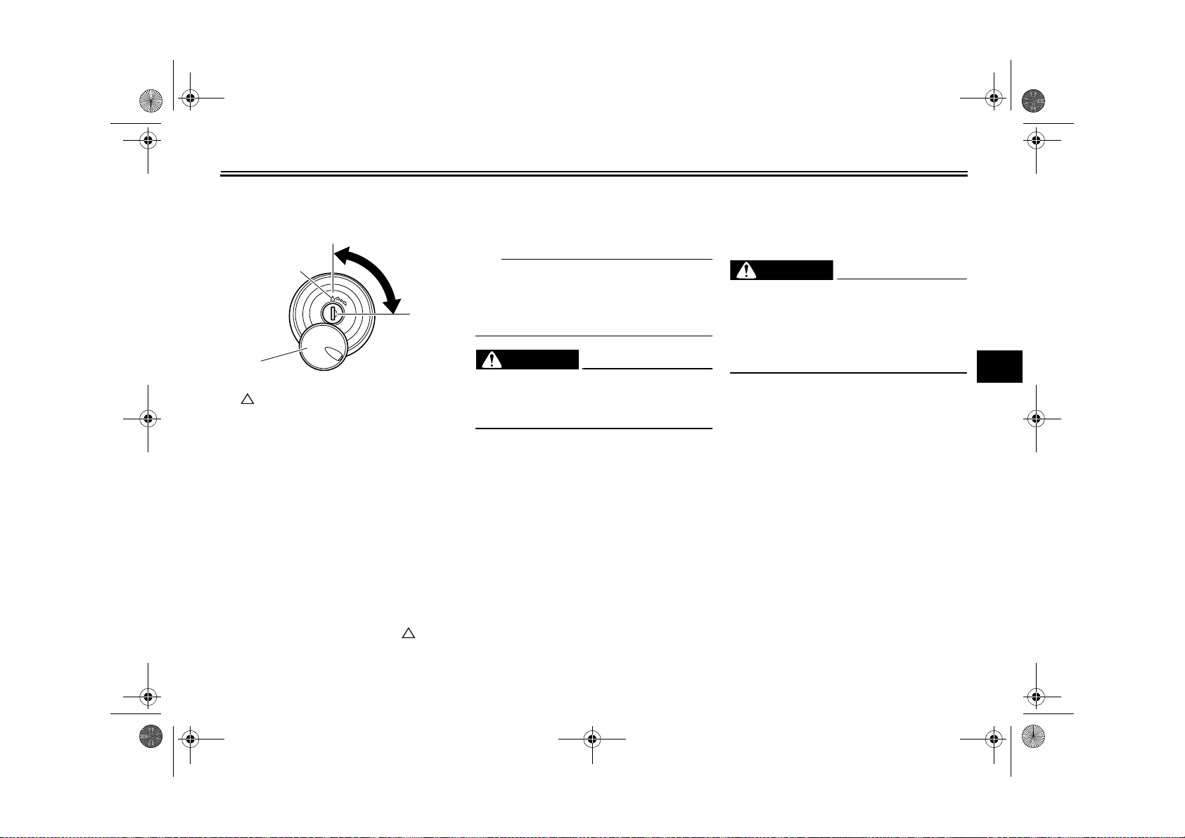
To lock the steering
12
1. Push.
2. Turn.
1. Turn the handlebars all the way to
the left.
2. Push the key in from the “OFF” po-
sition, and then turn it to “LOCK”
while still pushing it.
3. Remove the key.
4-1
U27D11E0.book Page 2 Monday, July 11, 2011 11:15 AM
INSTRUMENT AND CONTROL FUNCTIONS
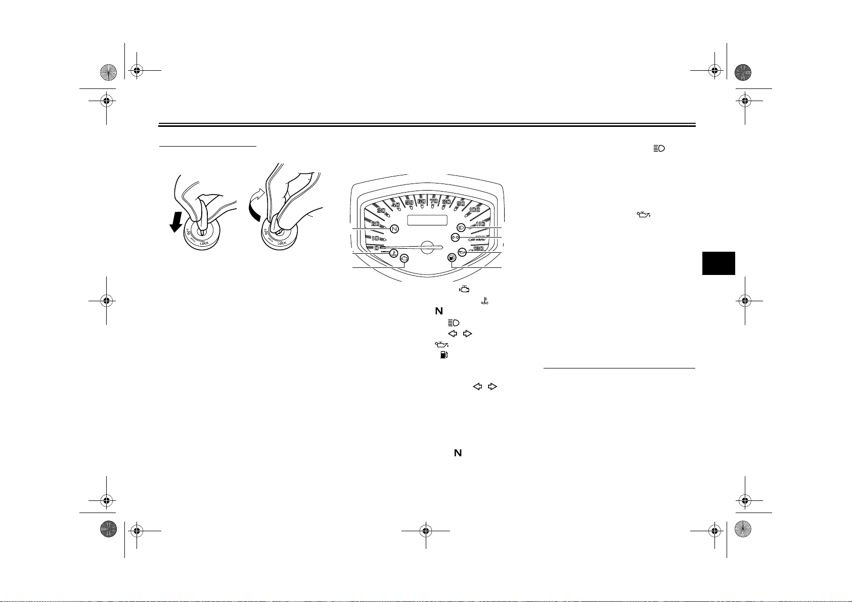
To unlock the steering
12
1. Push.
2. Turn.
Push the key in, and then turn it to
“OFF” while still pushing it.
EAU49391
Indicator lights and warning lights
3
2
1
1. Engine trouble warning light “”
2. Coolant temperature warning light “”
3. Neutral indicator light “”
4. High beam indicator light “”
5. Turn signal indicator light “”
6. Oil level warning light “”
7. Fuel level warning light “”
Turn signal indicator light “”
This indicator light flashes when the
turn signal switch is pushed to the left or
right.
Neutral indicator light “”
This indicator light comes on when the
transmission is in the neutral position.
4
5
6
7
EAU11020
EAU11060
High beam indicator light “”
EAU11080
This indicator light comes on when the
high beam of the headlight is switched
on.
EAU11254
Oil level warning light “”
This warning light comes on if the engine oil level is low.
The electrical circuit of the warning light
can be checked by turning the key to
“ON”. The warning light should come
on for a few seconds, and then go off.
If the warning light does not come on
initially when the key is turned to “ON”,
or if the warning light remains on, have
a Yamaha dealer check the electrical
circuit.
TIP
● Even if the oil level is sufficient, the
warning light may flicker when
riding on a slope or during sudden
acceleration or deceleration, but
this is not a malfunction.
● This model is also equipped with a
self-diagnosis device for the oil
level detection circuit. If a problem
is detected in the oil level detection
4
4-2
U27D11E0.book Page 3 Monday, July 11, 2011 11:15 AM
INSTRUMENT AND CONTROL FUNCTIONS
circuit, the following cycle will be
repeated until the malfunction is
corrected: The oil level warning
light will flash ten times, then go off
for 2.5 seconds. If this occurs,
have a Yamaha dealer check the
vehicle.
Fuel level warning light “”
This warning light comes on when the
4
fuel level has dropped to a very low level. (See page 4-5.) When this occurs,
refuel as soon as possible.
The electrical circuit of the warning light
can be checked by turning the key to
“ON”. The warning light should come
on for a few seconds, and then go off.
If the warning light does not come on
initially when the key is turned to “ON”,
or if the warning light remains on, have
a Yamaha dealer check the electrical
circuit.
TIP
This model is also equipped with a selfdiagnosis device for the fuel level detection circuit. If a problem is detected
in the fuel level detection circuit, the following cycle will be repeated until the
EAU50781
malfunction is corrected: The fuel level
warning light will flash eight times, and
then go off for 3.0 seconds. If this occurs, have a Yamaha dealer check the
vehicle.
EAU11446
Coolant temperature warning
light “”
This warning light comes on if the engine overheats. If this occurs, stop the
engine immediately and allow the engine to cool.
The electrical circuit of the warning light
can be checked by turning the key to
“ON”. The warning light should come
on for a few seconds, and then go off.
If the warning light does not come on
initially when the key is turned to “ON”,
or if the warning light remains on, have
a Yamaha dealer check the electrical
circuit.
ECA10021
NOTICE
Do not continue to operate the engine if it is overheating.
4-3
TIP
● For radiator-fan-equipped vehi-
cles, the radiator fan(s) automatically switch on or off according to
the coolant temperature in the radiator.
● If the engine overheats, see page
7-37 for further instructions.
EAU42774
Engine trouble warning light “”
This warning light comes on if a problem is detected in the electrical circuit
monitoring the engine. If this occurs,
have a Yamaha dealer check the selfdiagnosis system. (See page 4-6 for an
explanation of the self-diagnosis device.)
The electrical circuit of the warning light
can be checked by turning the key to
“ON”. The warning light should come
on for a few seconds, and then go off.
If the warning light does not come on
initially when the key is turned to “ON”,
or if the warning light remains on, have
a Yamaha dealer check the electrical
circuit.
U27D11E0.book Page 4 Monday, July 11, 2011 11:15 AM
INSTRUMENT AND CONTROL FUNCTIONS
EAU50692
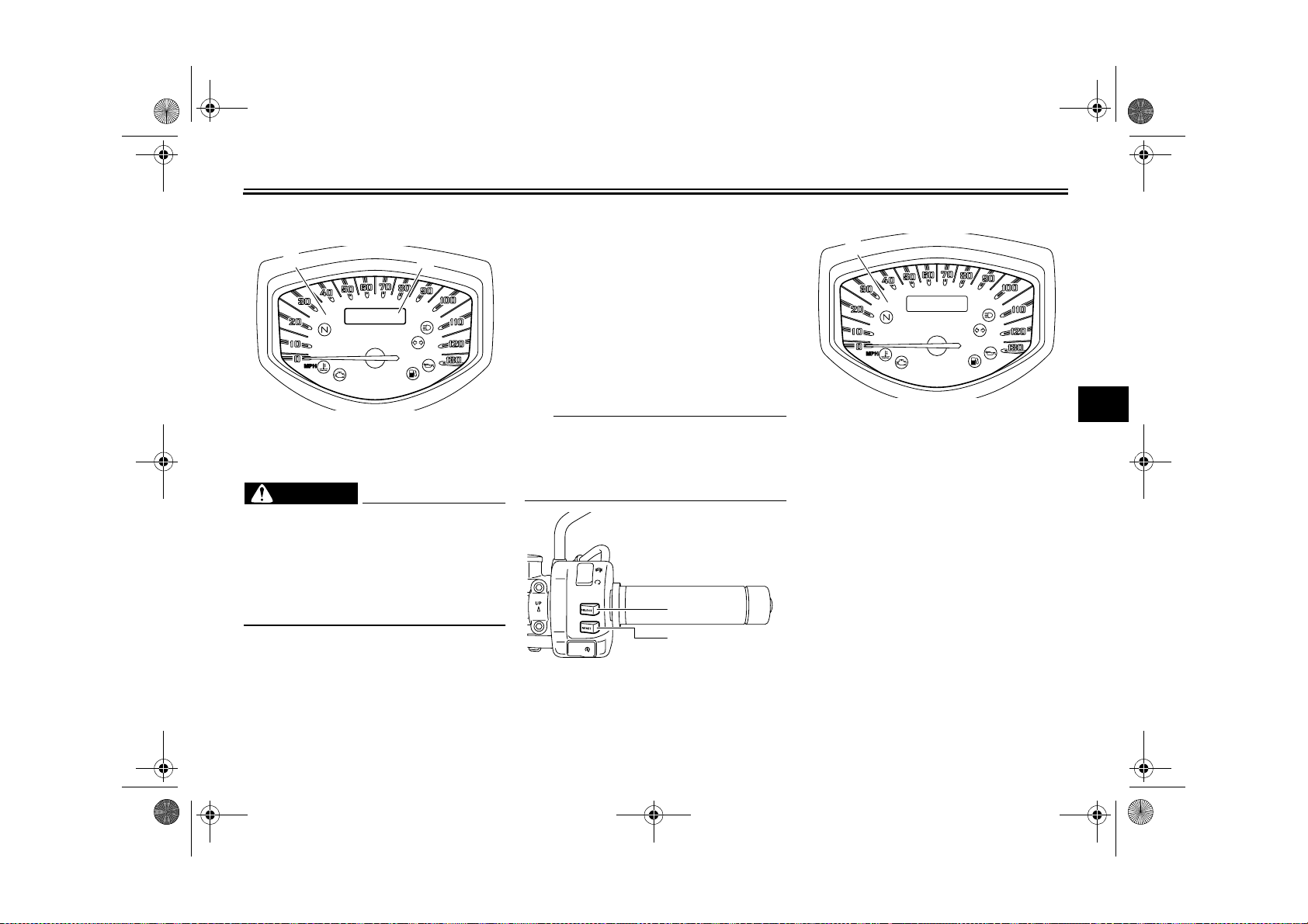
Multi-function meter unit
21
1. Speedometer
2. Odometer/tripmeter/fuel reserve tripmeter/fuel meter/clock
EWA12422
WARNING
Be sure to stop the vehicle before
making any setting changes to the
multi-function meter unit. Changing
settings while riding can distract the
operator and increase the risk of an
accident.
The multi-function meter unit is
equipped with the following:
● a speedometer
● an odometer
● two tripmeters (which show the
distance traveled since they were
last set to zero)
● a fuel reserve tripmeter (which
shows the distance traveled on the
fuel reserve)
● a fuel meter
● a clock
● a self-diagnosis device
● a brightness control mode
TIP
Be sure to turn the key to “ON” before
using the “SELECT” and “RESET”
switches, except for setting the brightness control mode.
1
2
1. “SELECT” switch
2. “RESET” switch
Speedometer
1
1. Speedometer
When the key is turned to “ON”, the
speedometer needle will sweep once
across the speed range and then return
to zero in order to test the electrical circuit.
4
4-4
U27D11E0.book Page 5 Monday, July 11, 2011 11:15 AM
INSTRUMENT AND CONTROL FUNCTIONS
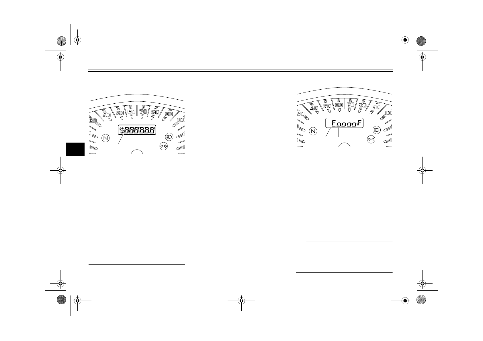
Odometer, tripmeters, fuel reserve
tripmeter, fuel meter and clock
4
1. Odometer/tripmeter/fuel reserve tripmeter/fuel meter/clock
1
Push the “SELECT” switch to change
the display between the odometer
mode “Odo”, the tripmeter modes “Trip
1” and “Trip 2”, the fuel meter mode,
and the clock mode in the following order:
Odo → Trip 1 → Trip 2 → Fuel meter →
Clock → Odo
TIP
Push the “RESET” switch for less than
one second to display the clock for five
seconds, regardless of the currently selected display mode.
If the fuel level warning light comes on
(see page 4-2), the display will automatically change to the fuel reserve
tripmeter mode “Trip F” and start counting the distance traveled from that
point. In that case, push the “SELECT”
switch to change the display between
the various tripmeter, odometer, fuel
meter, and clock modes in the following
order:
Trip F → Trip 1 → Trip 2 → Fuel meter
→ Clock → Odo → Trip F
To reset a tripmeter, select it by pushing the “SELECT” switch, and then
push the “RESET” switch for at least
one second. If you do not reset the fuel
reserve tripmeter manually, it will reset
itself automatically, and the display will
return to the prior mode after refueling
and traveling 5 km (3 mi).
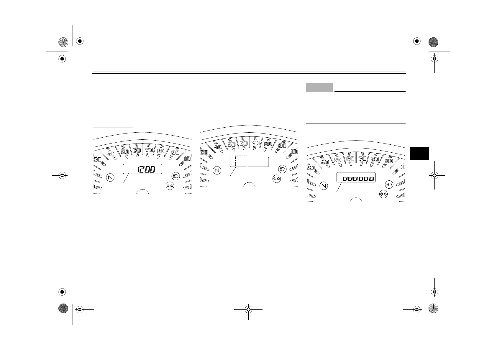
Fuel meter
1 2
1. Fuel meter
2. Segment
The fuel meter indicates the amount of
fuel in the fuel tank. The display segments of the fuel meter disappear towards “E” (Empty) as the fuel level
decreases. When the fuel meter changes from two segments to only one segment, approximately 5.0 L (1.32 US gal,
1.10 Imp.gal) of fuel remains in the fuel
tank. Be sure to refuel as soon as possible.
TIP
If the display is showing another function when this occurs, the display will
automatically change to the fuel meter
mode.
4-5
U27D11E0.book Page 6 Monday, July 11, 2011 11:15 AM
INSTRUMENT AND CONTROL FUNCTIONS
The fuel level warning light comes on
and the display switches to the fuel reserve tripmeter mode “Trip F” when the
fuel level is very low. Refuel as soon as
possible to avoid running out of fuel.
To set the clock
1
1. Clock
1. Push the “SELECT” switch to
change the display to the clock
mode.
2. Push the “SELECT” and “RESET”
switches together for at least three
seconds.
3. When the hour digits start flashing,
push the “SELECT” switch to set
the hours.
4. Push the “RESET” switch, and the
minute digits will start flashing.
5. Push the “SELECT” switch to set
the minutes.
6. Push the “RESET” switch and then
release it to start the clock.
Self-diagnosis device
1
1. Error code display
This model is equipped with a self-diagnosis device for various electrical circuits.
If a problem is detected in any of those
circuits, the engine trouble warning light
will come on and the display will indicate an error code.
If the display indicates any error codes,
note the code number, and then have a
Yamaha dealer check the vehicle.
4-6
ECA11590
NOTICE
If the display indicates an error
code, the vehicle should be checked
as soon as possible in order to avoid
engine damage.
Brightness control mode
4
1
1. Brightness level
This function allows you to adjust the
brightness of the multi-function meter
unit panel to suit the outside lighting
conditions.
To set the brightness
1. Turn the key to “OFF”.
2. Push and hold the “SELECT”
switch.
U27D11E0.book Page 7 Monday, July 11, 2011 11:15 AM
INSTRUMENT AND CONTROL FUNCTIONS
3. Turn the key to “ON”, and then release the “SELECT” switch after
five seconds.
4. Adjust the multi-function meter unit
panel brightness level by pushing
the “SELECT” switch.
5. Push the “RESET” switch.
The display will change to the prior
mode.
4
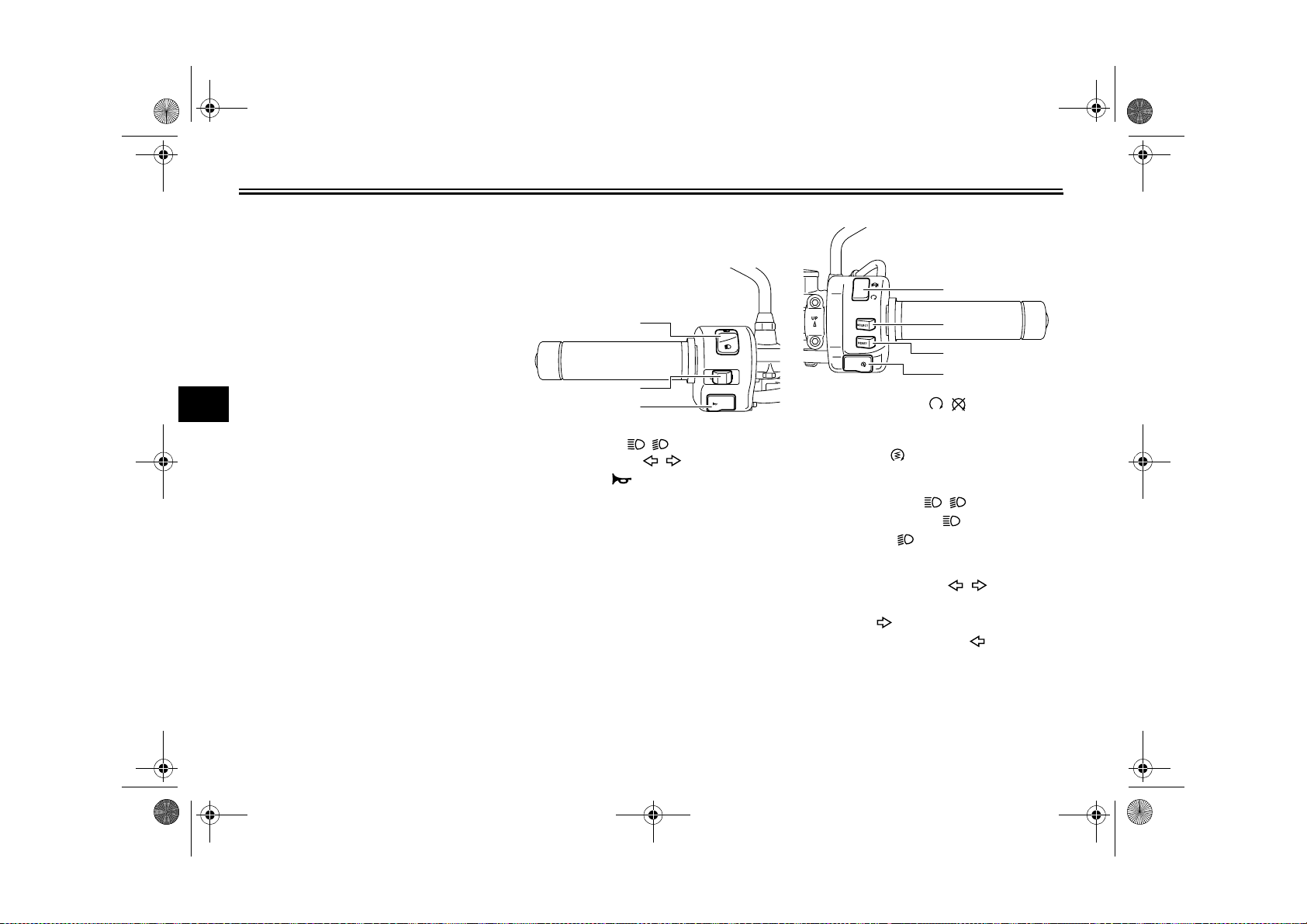
Handlebar switches
Left
1
2
3
1. Dimmer switch “ / ”
2. Turn signal switch “ / ”
3. Horn switch “”
EAU12349
Right
1
2
3
4
1. Engine stop switch “ / ”
2. “SELECT” switch
3. “RESET” switch
4. Start switch “”
EAU12400
Dimmer switch “ / ”
Set this switch to “” for the high
beam and to “” for the low beam.
EAU12430
Turn signal switch “ / ”
To signal a right-hand turn, push this
switch to “”. To signal a left-hand
turn, push this switch to “”. When re-
leased, the switch returns to the center
position.
Since this model is equipped with a
self-canceling system, the turn signal
lights will self-cancel after the vehicle
4-7
U27D11E0.book Page 8 Monday, July 11, 2011 11:15 AM
INSTRUMENT AND CONTROL FUNCTIONS
has traveled both about 150 m (490 ft)
and for approximately 15 seconds.
However, the turn signal lights can also
be canceled manually by pushing the
switch in after it has returned to the center position.
TIP
The self-canceling system only operates when the vehicle is moving, so that
the turn signal lights will not self-cancel
while you are stopped at an intersection.
EAU12500
Horn switch “”
Press this switch to sound the horn.
EAU12660
Engine stop switch “ / ”
Set this switch to “” before starting
the engine. Set this switch to “” to
stop the engine in case of an emergency, such as when the vehicle overturns
or when the throttle cable is stuck.
Start switch “”
EAU12711
Push this switch to crank the engine
with the starter. See page 6-1 for starting instructions prior to starting the engine.
EAU41700
The engine trouble warning light will
come on when the key is turned to “ON”
and the start switch is pushed, but this
does not indicate a malfunction.
EAU44602
“SELECT” switch
This switch is used to perform selections in the odometer and tripmeters, to
set the clock and to set the brightness
control mode of the multi-function
meter unit.
See “Multi-function meter unit” on page
4-4 for detailed information.
EAU42535
“RESET” switch
This switch is used to reset the tripmeters, to set the clock and to set the
brightness control mode of the multifunction meter unit.
See “Multi-function meter unit” on page
4-4 for detailed information.
4-8
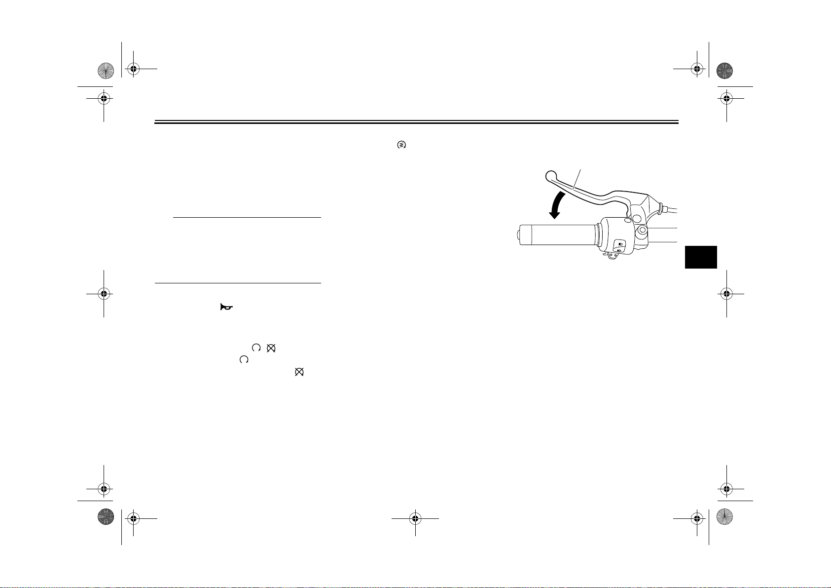
EAU12820
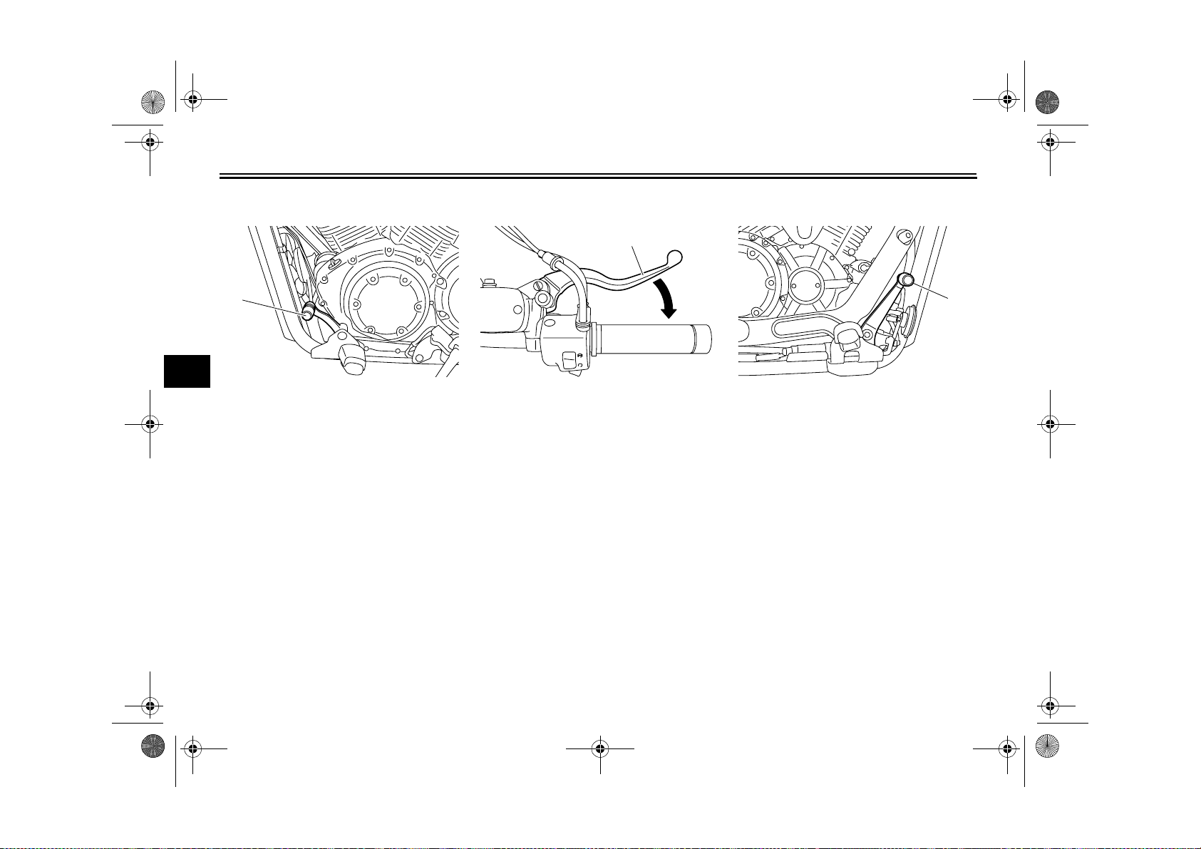
Clutch lever
1
4
1. Clutch lever
The clutch lever is located at the left
handlebar grip. To disengage the
clutch, pull the lever toward the handlebar grip. To engage the clutch, release
the lever. The lever should be pulled
rapidly and released slowly for smooth
clutch operation.
The clutch lever is equipped with a
clutch switch, which is part of the ignition circuit cut-off system. (See page
4-16.)
U27D11E0.book Page 9 Monday, July 11, 2011 11:15 AM
INSTRUMENT AND CONTROL FUNCTIONS
Shift pedal
1
4
1. Shift pedal
The shift pedal is located on the left
side of the motorcycle and is used in
combination with the clutch lever when
shifting the gears of the 5-speed constant-mesh transmission equipped on
this motorcycle.
EAU12871
EAU12890
Brake lever
1
1. Brake lever
The brake lever is located at the right
handlebar grip. To apply the front
brake, pull the lever toward the handlebar grip.
EAU12941
Brake pedal
1
1. Brake pedal
The brake pedal is on the right side of
the motorcycle. To apply the rear
brake, press down on the brake pedal.
4-9
U27D11E0.book Page 10 Monday, July 11, 2011 11:15 AM
INSTRUMENT AND CONTROL FUNCTIONS
EAU13122
Fuel tank cap
3
2
4
1
1. Fuel tank cap lock cover
2. “” mark
3. Lock.
4. Unlock.
To remove the fuel tank cap
Slide the fuel tank cap lock cover open,
insert the key into the lock, and then
turn it 1/4 turn clockwise. The lock will
be released and the fuel tank cap can
be removed.
To install the fuel tank cap
1. Insert the fuel tank cap into the
tank opening with the key inserted
in the lock and with the “” mark
facing forward.
2. Turn the key counterclockwise to
the original position, remove it, and
then close the lock cover.
TIP
The fuel tank cap cannot be installed
unless the key is in the lock. In addition,
the key cannot be removed if the cap is
not properly installed and locked.
EWA10131
WARNING
Make sure that the fuel tank cap is
properly installed before riding.
Leaking fuel is a fire hazard.
EAU13221
Fuel
Make sure there is sufficient gasoline in
the tank.
EWA10881
WARNING
Gasoline and gasoline vapors are
extremely flammable. To avoid fires
and explosions and to reduce the
risk of injury when refueling, follow
these instructions.
1. Before refueling, turn off the engine and be sure that no one is sitting on the vehicle. Never refuel
while smoking, or while in the vicinity of sparks, open flames, or
other sources of ignition such as
the pilot lights of water heaters and
clothes dryers.
2. Do not overfill the fuel tank. When
refueling, be sure to insert the
pump nozzle into the fuel tank filler
hole. Stop filling when the fuel
reaches the bottom of the filler
tube. Because fuel expands when
it heats up, heat from the engine or
the sun can cause fuel to spill out
of the fuel tank.
4
4-10
U27D11E0.book Page 11 Monday, July 11, 2011 11:15 AM
INSTRUMENT AND CONTROL FUNCTIONS
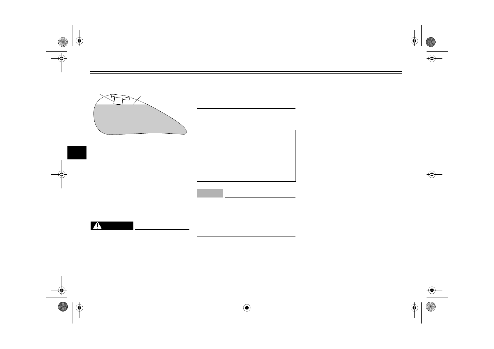
1 2
1. Fuel tank filler tube
4
2. Maximum fuel level
3. Wipe up any spilled fuel immediately. NOTICE: Immediately wipe
off spilled fuel with a clean, dry,
soft cloth, since fuel may deteriorate painted surfaces or plastic
parts.
[ECA10071]
4. Be sure to securely close the fuel
tank cap.
WARNING
Gasoline is poisonous and can
cause injury or death. Handle gasoline with care. Never siphon gasoline by mouth. If you should swallow
some gasoline or inhale a lot of gasoline vapor, or get some gasoline in
your eyes, see your doctor immedi-
EWA15151
ately. If gasoline spills on your skin,
wash with soap and water. If gasoline spills on your clothing, change
your clothes.
EAU50790
Recommended fuel:
Unleaded gasoline only
Fuel tank capacity:
15.0 L (3.96 US gal, 3.30 Imp.gal)
Fuel reserve amount (when only
one segment of the fuel meter remains):
5.0 L (1.32 US gal, 1.10 Imp.gal)
ECA11400
NOTICE
Use only unleaded gasoline. The use
of leaded gasoline will cause severe
damage to internal engine parts,
such as the valves and piston rings,
as well as to the exhaust system.
Your Yamaha engine has been designed to use regular unleaded gasoline with a pump octane number
[(R+M)/2] of 86 or higher, or a research
octane number of 91 or higher. If
knocking (or pinging) occurs, use a
4-11
gasoline of a different brand or premium unleaded fuel. Use of unleaded fuel
will extend spark plug life and reduce
maintenance costs.
Gasohol
There are two types of gasohol: gasohol containing ethanol and that containing methanol. Gasohol containing
ethanol can be used if the ethanol content does not exceed 10% (E10). Gasohol containing methanol is not
recommended by Yamaha because it
can cause damage to the fuel system
or vehicle performance problems.
U27D11E0.book Page 12 Monday, July 11, 2011 11:15 AM
INSTRUMENT AND CONTROL FUNCTIONS
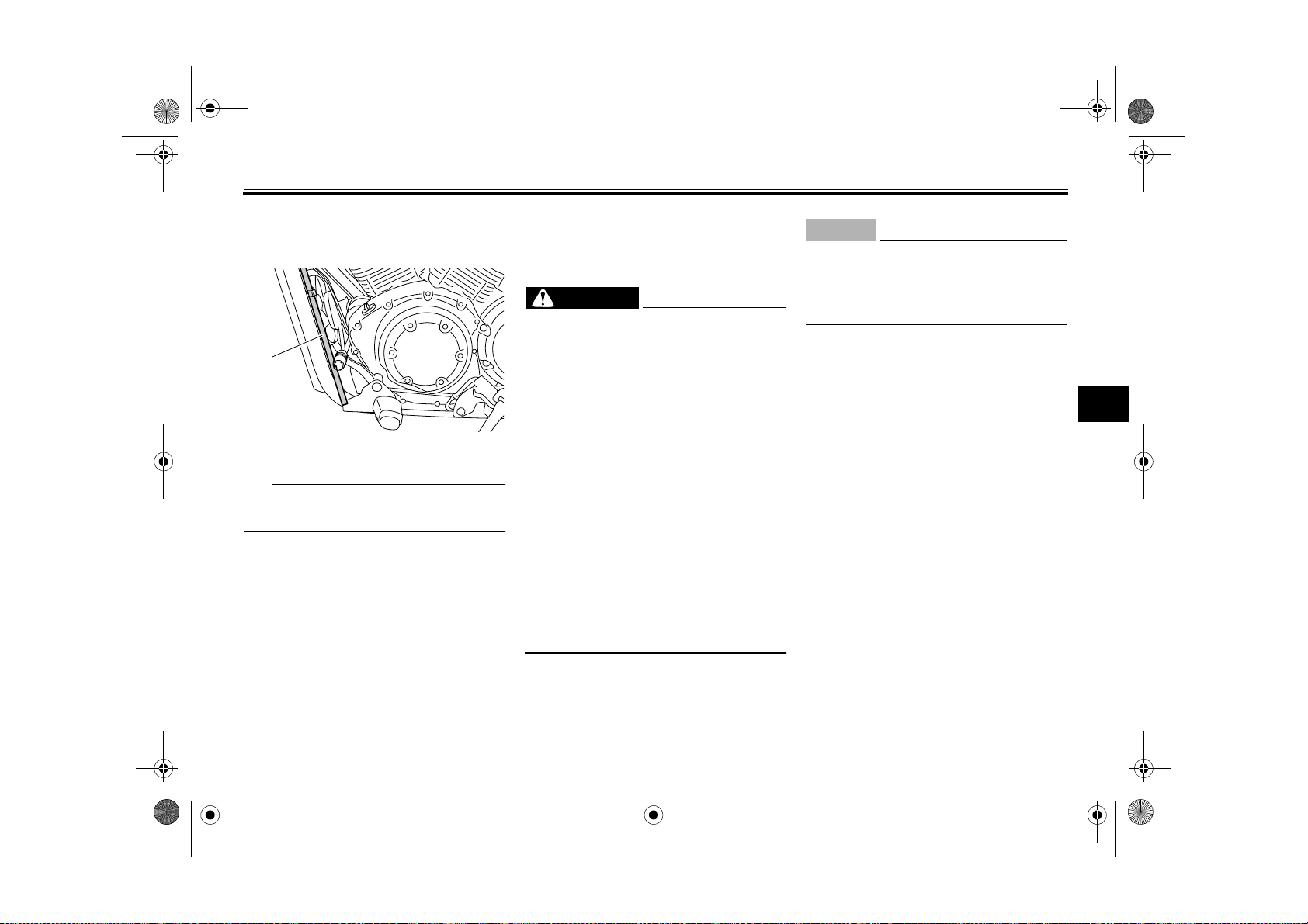
EAU48760
Fuel tank breather/overflow hose
1
1. Fuel tank breather/overflow hose
TIP
For California: See page 7-11 for
breather hose information.
Before operating the motorcycle:
● Check the fuel tank breather/over-
flow hose connection.
● Check the fuel tank breather/over-
flow hose for cracks or damage,
and replace it if damaged.
● Make sure that the end of the fuel
tank breather/overflow hose is not
blocked, and clean it if necessary.
EAU13433
Catalytic converter
This model is equipped with a catalytic
converter in the exhaust system.
EWA10862
WARNING
The exhaust system is hot after operation. To prevent a fire hazard or
burns:
● Do not park the vehicle near
possible fire hazards such as
grass or other materials that
easily burn.
● Park the vehicle in a place
where pedestrians or children
are not likely to touch the hot
exhaust system.
● Make sure that the exhaust sys-
tem has cooled down before doing any maintenance work.
● Do not allow the engine to idle
more than a few minutes. Long
idling can cause a build-up of
heat.
ECA10701
NOTICE
Use only unleaded gasoline. The use
of leaded gasoline will cause unrepairable damage to the catalytic
converter.
4
4-12
U27D11E0.book Page 13 Monday, July 11, 2011 11:15 AM
INSTRUMENT AND CONTROL FUNCTIONS
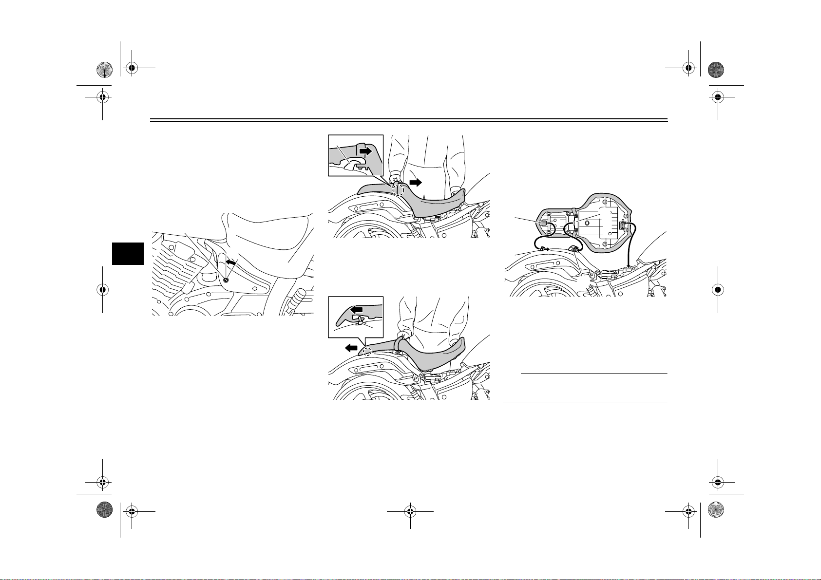
Seat
To remove the seat
1. Insert the key into the seat lock,
turn it counterclockwise, and then
lift the front of the seat up.
1
4
1. Seat lock
2. Unlock.
2. Pull the seat forward as shown to
unhook it from the center seat
holder.
2
EAU50680
1
1. Center seat holder
3. Pull the seat rearward to unhook it
from the rear seat holder, and then
pull it off.
1
1. Rear seat holder
2. Slide the seat rearward to fit the
slot in its bottom over the center
seat holder.
3. Push the front of the seat down to
lock it in place.
1
3
2
4
1. Projection
2. Rear seat holder
3. Slot
4. Center seat holder
4. Remove the key.
TIP
Make sure that the seat is properly secured before riding.
To install the seat
1. Insert the projection on the rear of
the seat into the rear seat holder.
4-13
 Loading...