

Yamaha RXV-800 Service manual
AV RECEIVER
RX-V800/RX-V800RDS/HTR-5280
SERVICE MANUAL
IMPORTANT NOTICE
This manual has been provided for the use of authorized YAMAHA Retailers and their service personnel.
It has been assumed that basic service procedures inherent to the industry, and more specifically YAMAHA Products, are already
known and understood by the users, and have therefore not been restated.
WARNING: Failure to follow appropriate service and safety procedures when servicing this product may result in personal
IMPORTANT: The presentation or sale of this manual to any individual or firm does not constitute authorization, certification or
The data provided is believed to be accurate and applicable to the unit(s) indicated on the cover. The research, engineering, and
service departments of YAMAHA are continually striving to improve YAMAHA products. Modifications are, therefore, inevitable
and specifications are subject to change without notice or obligation to retrofit. Should any discrepancy appear to exist, please
contact the distributor's Service Division.
WARNING: Static discharges can destroy expensive components. Discharge any static electricity your body may have
IMPORTANT: Turn the unit OFF during disassembly and part replacement. Recheck all work before you apply power to the unit.
injury, destruction of expensive components, and failure of the product to perform as specified. For these reasons,
we advise all YAMAHA product owners that any service required should be performed by an authorized
YAMAHA Retailer or the appointed service representative.
recognition of any applicable technical capabilities, or establish a principle-agent relationship of any form.
RX-V800/RX-V800RDS/HTR-5280
accumulated by grounding yourself to the ground buss in the unit (heavy gauge black wires connect to this buss).
■ CONTENTS
TO SERVICE PERSONNEL .......................................... 1
IMPEDANCE SELECTOR ............................................. 1
SPECIFICATIONS.......................................................... 2
REMOTE CONTROL TRANSMITTER .......................... 3
FRONT PANELS............................................................ 4
REAR PANELS .......................................................... 5~6
INTERNAL VIEW ........................................................... 7
DISASSEMBLY PROCEDURES ................................... 8
SELF DIAGNOSIS FUNCTION (DIAG) ................... 9~23
100727
AMP ADJUSTMENT .................................................... 23
DISPLAY DAT A ........................................................... 24
IC DATA ................................................................. 25~31
BLOCK DIAGRAM................................................. 32~35
PRINTED CIRCUIT BOARD .................................. 36~59
PIN CONNECTION DIAGRAM .............................. 60~61
SCHEMATIC DIAGRAM ........................................ 62~68
PARTS LIST........................................................... 69~87
REMOTE CONTROL TRANSMITTER .................. 88~89
P.O.Box 1, Hamamatsu, Japan
RX-V800/RX-V800RDS/HTR-5280
■ TO SERVICE PERSONNEL
1. Critical Components Information
Components having special characteristics are marked s
and must be replaced with parts having specifications equal
to those originally installed.
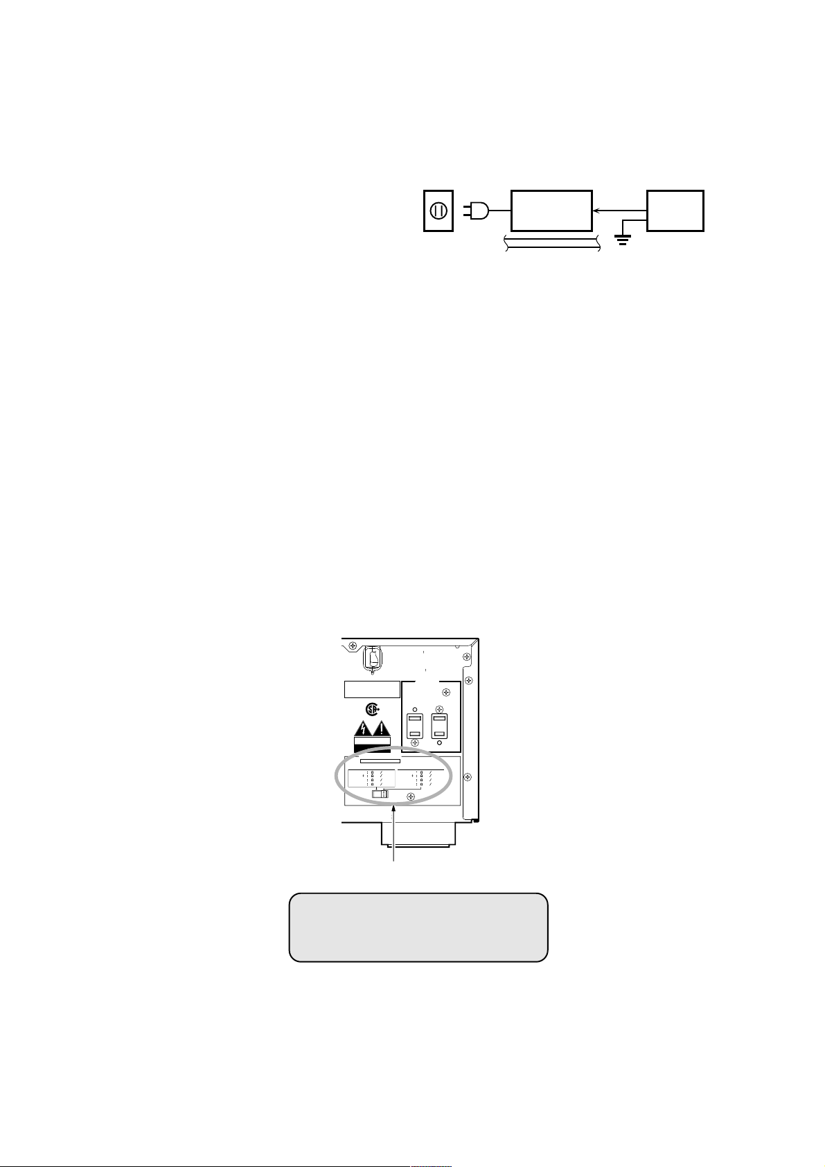
2. Leakage Current Measurement (For 120V Models Only)
When service has been completed, it is imperative to verify
that all exposed conductive surfaces are properly insulated
from supply circuits.
● Meter impedance should be equivalent to 1500 ohm shunted
by 0.15µF.
● Leakage current must not exceed 0.5mA.
● Be sure to test for leakage with the AC plug in both polarities.
WALL
OUTLET
EQUIPMENT
UNDER TEST
INSULATING
TABLE
AC LEAKAGE
TESTER OR
EQUIVALENT
WARNING: CHEMICAL CONTENT NOTICE!
The solder used in the production of this product contains LEAD. In addition, other electrical/electronic and /or plastic
(where applicable) components may also contain traces of chemicals found by the California Health and Welfare Agency
(and possibly other entities) to cause cancer and/or birth defects or other reproductive harm.
DO NOT PLACE SOLDER, ELECTRICAL/ELECTRONIC OR PLASTIC COMPONENTS IN YOUR MOUTH FOR ANY REASON WHATSOEVER!
Avoid prolonged, unprotected contact between solder and your skin! When soldering, do not inhale solder fumes or expose
eyes to solder/flux vapor!
If you come in contact with solder or components located inside the enclosure of this product, wash your hands before
handling food.
■ IMPEDANCE SELECTOR
TO REDUCE THE RISK
WARNING
OF FIRE OR ELECTRIC SHOCK,
DO NOT EXPOSE THIS APPLIANCE
TO RAIN OR MOISTURE.
RISQUE DE CHOC
ATTENTION
ELECTRIQUE NE PAS OUVRIR.
SPEAKER
SPEAKER
SPEAKER
SPEAKER
MAIN A OR B
CENTER
REAR
AC OUTLETS
SWITCHED
I20V 60Hz
I00W MAX. TOTAL
MIN.
8
MIN.
I6
BA
MIN.
8
MIN.
8
SPEAKER
SPEAKER
SPEAKER
SPEAKER
THIS DEVICE COMPLIES WITH PART 15 OF
THE FCC RULES. OPERATIONIS SUBJECT TO
THE CONDITION THAT THIS DEVICE DOES
NOT CAUSE HARMFUL INTERFERENCE.
US
CAUTION
RISK OF ELECTRIC SHOCK
DO NOT OPEN
IMPEDANCE SELECTOR
SET BEFORE POWER ON
MIN.
4
MAIN A OR B
MIN.
8
BA
CENTER
MIN.
6
MIN.
6
REAR
MANUFACTURED UNDER LICENSE FROM DIGITAL THEATER SYSTEMS, INC. US PAT.
NO.5,45I,942 AND OTHER WORLD-WIDE PATENTS ISSUED AND PENDING. "DTS",
"DTS DIGITAL SURROUND", ARE TRADEMARKS OF DIGITALTHEATER SYSTEMS, INC.
COPYRIGHT 1998 DIGITAL THEATER SYATEMS, INC, ALL RIGHTS RESERVED.
IMPEDANCE SELECTOR
WARNING:
Do not change the IMPEDANCE SELECTOR
switch setting while the power to this unit is
on, otherwise this unit may be damaged.
1

■ SPECIFICATIONS
■ Audio Section
Minimum RMS Output Power (Power Amp. Section)
(20 Hz to 20 kHz, 0.04% THD, 8 ohms)
MAIN .......................................................................100W + 100W
CENTER............................................................................... 100W
REAR ......................................................................100W + 100W
Maximum Power (EIAJ)
(1 kHz, 10% THD, 8 ohms)
MAIN .......................................................................140W + 140W
CENTER............................................................................... 140W
REAR ......................................................................140W + 140W
Dynamic Power Per Channel (IHF)
MAIN L/R (8/6/4/2 ohms)
[U model] ........................................................ 135/170/205/245 W
[C, A, B, G, L, R, T models] ........................... 125/160/195/230 W
DIN Standard Output Power Per Channel
(1 kHz, 0.7% THD, 4 ohms)
[G model]............................................................................. 140 W
Dynamic Headroom
8 ohms
[U model] ............................................................................. 1.3 dB
[C model]............................................................................. 1.0 dB
IEC Power
MAIN L/R (1 kHz, 0.04% THD, 8 ohms)
[G model].................................................................105W + 105W
Damping Factor
MAIN L/R (20 Hz to 20 kHz, 8 ohms).......................... 80 or more
Input Sensitivity / Input Impedance
PHONO MM ................................................... 2.5 mV / 47 k-ohms
CD, etc. ......................................................... 150 mV / 47 k-ohms
Maximum Input Signal Level
PHONO MM (1 kHz, 0.1% THD) ...................................... 100 mV
CD, etc. (1 kHz, 0.5% THD, Effect On) ................................ 2.2 V
Output Level / Output Impedance
REC OUT ..................................................... 150 mV / 0.9 k-ohms
PRE OUT .......................................................2.57 V / 1.2 k-ohms
SUB WOOFER [MAIN SP: Small] ...................... 4 V/1.2 k-ohms
Headphone Jack Rated Output / Impedance
1 kHz, 40 mV, 8 ohms ..................................... 0.15 V / 100 ohms
Frequency Response
Power Amp o n l y ( 5 H z t o 1 0 0 k H z ) ................................... 0/-3 dB
CD, etc. to MAIN SP OUT (10 Hz to 100 kHz).................. 0/-3 dB
RIAA Equalization Deviation
PHONO MM (20 Hz to 20 kHz) ....................................0 ± 0.5 dB
Total Harmonic Distortion
(20 Hz to 20 kHz)
PHONO MM, to REC OUT (1V) ..............................0.02% or less
CD, etc. to MAIN SP OUT (50 W / 8 ohms) ............0.04% or less
Signal to Noise Ratio (IHF-A network)
CD, etc. to MAIN SP OUT (Input shorted, Effect Off)
150 mV ....................................................................96 dB or more
200 mV ....................................................................98 dB or more
Residual Noise (IHF-A netwok)
MAIN L/R SP OUT ................................................. 150 µV or less
Channnel Separation
(Vol -30 dB, Effect Off)
PHONO (Input Shorted, 1 kHz) ..............................60 dB or more
PHONO (Input Shorted, 10 kHz) ............................55 dB or more
CD, etc.
(Input 5.1 k-ohms terminated, 1 kHz) .............
(Input 5.1 k-ohms terminated, 10 kHz) ...........
CD, etc.
Tone Control Characteristics
Bass: Boost/Cut ................................................ ±10 dB (50 Hz)
Turnover Frequency ............................................ 350 Hz
Treble: Boost/Cut .............................................. ±10 dB (20 kHz)
Turnover Frequency ........................................... 3.5 kHz
Filter Characteristics
MAIN, Rear SP Small (H.P.F.) ..........................90 Hz, 12 dB/oct.
SUBWOOFER (L.P.F.) ......................................90 Hz, 18 dB/oct.
Bass Extension
60 Hz ...................................................................................... 6 dB
■ Video Section
Video Signal Type
[U, C, R, T models] ..............................................................NTSC
[A, B, G, L, models]................................................................. PAL
Video Sigal Level
............................................................................ 1 Vp-p / 75 ohms
60 dB or more
45 dB or more
RX-V800/RX-V800RDS/HTR-5280
S-Video Sigal Level
Y ......................................................................... 1 Vp-p / 75 ohms
C .................................................................. 0.286 Vp-p / 75 ohms
Component Video Sigal Level
Y ......................................................................... 1 Vp-p / 75 ohms
Cb / Cr ............................................................. 0.7 Vp-p / 75 ohms
Maximum Input Level
.......................................................................................... 1.5 Vp-p
Sigal to Noise Ratio
.................................................................................50 dB or more
Monitor Out Frequency Response
S-Video Signal Level .................................5 Hz to 10 MHz, -3 dB
Component Signal Level.............................. DC to 30 MHz, -3 dB
■ FM Section
Tuning Range
[U, C models] ...................................................87.5 to 107.9 MHz
[R, T, A, B, G, L models].................................. 87.5 to 10 8.0 MHz
50 dB Quieting Sensitivity (IHF)
(100% Mod)
Mono .................................................................. 2.0 µV (17.3 dBf)
Stereo .................................................................. 25 µ V ( 3 9 . 2 d B f)
Usable Sensitivity (IHF)
Mono .................................................................. 1.0 µV (11.2 dBf)
Selectivity
at 400 kHz ............................................................................ 70 dB
Signal to Noise Ratio (IHF)
Mono / Stereo ..........................................................76 dB / 70 dB
Harmonic Distortion
(1 kHz)
Mono/Stereo................................................................. 0.2 / 0.3 %
Stereo Separation
1 kHz .................................................................................... 45 dB
Frequency Response
20 Hz to 15 kHz ..........................................................+0.5 / -2 dB
Antenna Input
......................................................................75 ohms unbalanced
■ AM Section
Tuning Range
[U, C, R, T models] ............................................530 to 1,710 kHz
[A, B, G, L models]............................................. 531 to 1,611 kHz
Usable Sensitivity
........................................................................................ 300 µV/m
Antenna
................................................................................. Loop Antenna
■ General
Power Supply
[U, C models] ......................................................AC 120 V, 60 Hz
[R models] ................................ AC 110/120/220/240 V, 50/60 Hz
[T model] .............................................................AC 220 V, 50 Hz
[A model ] ............................................................AC 240 V, 50 Hz
[B, G, L models] .................................................. AC 230 V, 50 Hz
Power Consumption
[U model] ............................................................................. 260 W
[C model] .............................................................. 300 W / 360 VA
[R, T, A, B, G, L models]..................................................... 300 W
Maximum Power Consumption
(5ch Drive, 10% THD)
[R model] ............................................................................. 585 W
AC Outlets
2 switched outlets
[U, C, R, T G, L models] .................................... 100W max., total
1 switched outlets
[A, B models]............................................................... 100W max.
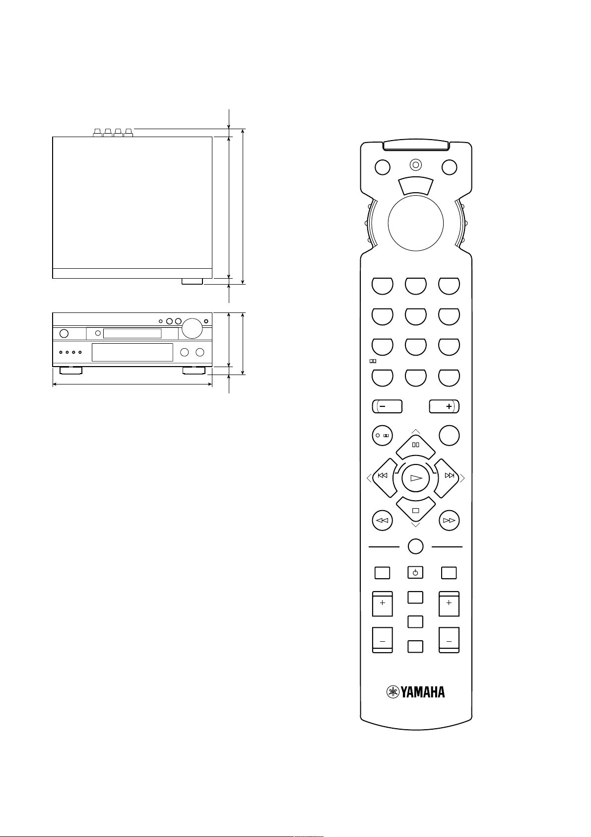
Dimensions (W x H x D)
............................. 435 x 171 x 431.5 mm (17-1/8" x 6-3/4" x 17")
Weight
.................................................................... 15.0 kg (33 lbs. 1 oz.)
Accessories
Remote control transmitter, Manganese batteries, Indoor FM
antenna, AM loop antenna
* Specifications are subject to change without notice.
U .......... U.S.A. model C ...... Canadian model
A .......... Australian model B ...... British model
G .......... European model L....... Singa p o r e model
R .......... General model T....... China model
2
RX-V800/RX-V800RDS/HTR-5280
• DIMENSIONS
Unit : mm (inch)
435 (17-1/8")
21.5
16
150 (5-7/8") 394 (15-1/2")21
(7/8")
(5/8")
(13/16")
431.5 (17")
171 (6-3/4")
■ REMOTE CONTROL
TRANSMITTER
DSP INPUT
T
/
U
P
N
S
D
CHURCH
HALL
CD
1
ROCK
DVD
4
MONO MOVIE
CD-R
7
yy
/DTS SUR.
PHONO
0
CH
VCR REC
/
TEST
TUNER
ENTERTAINMENT
D-TV/LD
1-MOVIE
CBL/SAT
6.1/ES
6CH INPUT
ENTER
INDEX
DISC SKIP
PRESET
D
O
C
2
5
8
E
S
E
T
JAZZ
MD/TAPE
3
TV SPORTS
VCR 1
6
THTR-2
VCR 2/DVR
9
EFFECT
V-AUX
>
10
CH
DISPLAY
A/B
A/B/C/D/E
DIR A DIR B
TITLE
LEVEL
POWER
SELECT
O
N
N
E
S
E
C
R
POWER
AV
STANDBY
TV
INPUT
TV
TV VOL
SLEEP
MUTE
MENU
SET MENU
POWER
I
VOLUME
3
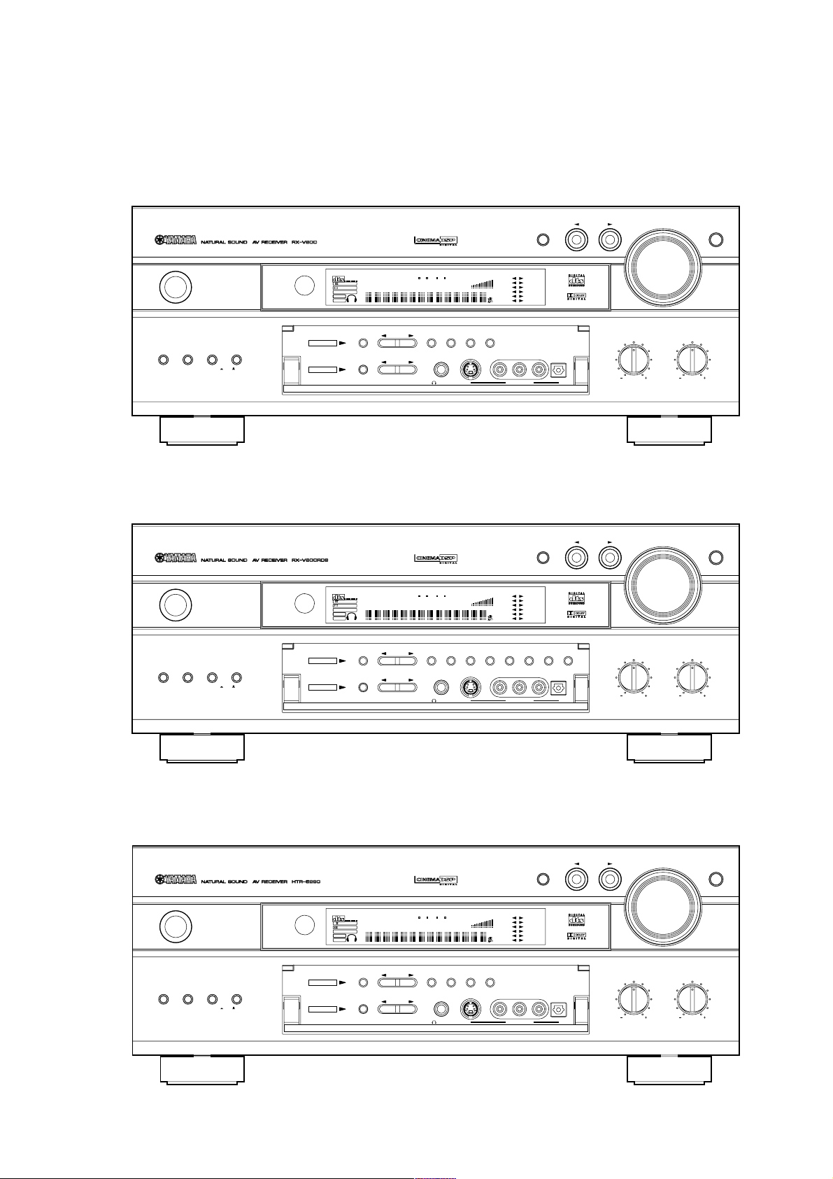
■ FRONT PANELS
RX-V800 (U, C, A, L, R, T models) • U, C and A models → BL (Black model)
• L model → GD (Gold model)
• R and T models → BL (Black model) and GD (Gold model)
RX-V800/RX-V800RDS/HTR-5280
PRESET/
TUNING
PROGRAM
PTY RT CTPS
PTY HOLD
EON
STEREO AUTO
NEWS INFO AFFAIRS SPORT
TUNED
PRESET
/TUNING
EDIT
SILENT
ZONE 2
SLEEPMEMORY
FM/AM
MEMORY
MAN'L/AUTO FMAUTO/MAN'L MONO
VOLUME
CBL/SAT
VCR2/DVR
TUNING
MODE
STANBY
/ON
SPEAKERS
AB
BASS
EXTENSION
PROCESSOR
DIRECT
OFFON
TUNER
VIRTUAL
DTS MOVIE THEATER 12
DOLBY DIGITAL
DIGITAL
PRO LOGIC ENTERTAINMENT
PRO LOGIC
DSP
6.1/ES
SP
PCM
A B
A/B/C/D/E
EFFECT
DSP
RX-V800RDS (B, G models) • B model → BL (Black model)
• G model → BL (Black model), GD (Gold model) and TI (Titan model)
STANBY
VIRTUAL
DTS MOVIE THEATER 12
DOLBY DIGITAL
DIGITAL
PRO LOGIC ENTERTAINMENT
/ON
6.1/ES
PCM
PRO LOGIC
DSP
SP
A B
PTY RT CTPS
PTY HOLD
EON
STEREO AUTO
NEWS INFO AFFAIRS SPORT
TUNED
VOLUME
ZONE 2
SLEEPMEMORY
CBL/SAT
VCR2/DVR
CABLE
D-TV/LD
VCR 1
V-AUX
CABLE
D-TV/LD
VCR 1
V-AUX
VIDEO AUX
INPUT MODE
DVD
MD/TAPE
CD-R
TUNER
CD
PHONO
INPUT MODE
DVD
MD/TAPE
CD-R
TUNER
CD
PHONO
INPUT
OPTICALAUDIOLVIDEOS VIDEOPHONES
R
INPUT
VOLUME
BASS
VOLUME
6CH INPUT
TREBLE
6CH INPUT
SPEAKERS
AB
BASS
EXTENSION
PROCESSOR
DIRECT
OFFON
TUNER
PRESET/
TUNING
PROGRAM
PRESET
/TUNING
EDIT
FM/AM
MAN'L/AUTO FMAUTO/MAN'L MONO
SILENT
A/B/C/D/E
EFFECT
DSP
MEMORY
RDS MODE
TUNING
EON PTY SEEK
/FREQ
MODE
MODE START
OPTICALAUDIO
LVIDEOS VIDEOPHONES
R
VIDEO AUX
HTR-5280 (U, C, A, T models) • U, C and A models → BL (Black model)
• T model → GD (Gold model)
INPUT MODE
STANBY
/ON
SPEAKERS
AB
BASS
EXTENSION
PROCESSOR
DIRECT
OFFON
TUNER
PRESET/
TUNING
PROGRAM
PTY RT CTPS
PTY HOLD
EON
STEREO AUTO
NEWS INFO AFFAIRS SPORT
TUNED
PRESET
/TUNING
EDIT
SILENT
FM/AM
ZONE 2
SLEEPMEMORY
VIRTUAL
DTS MOVIE THEATER 12
DOLBY DIGITAL
DIGITAL
PRO LOGIC ENTERTAINMENT
PRO LOGIC
DSP
6.1/ES
SP
PCM
A B
A/B/C/D/E
EFFECT
DSP
VOLUME
D-TV/LD
CBL/SAT
VCR2/DVR
TUNING
MODE
MEMORY
MAN'L/AUTO FMAUTO/MAN'L MONO
CABLE
DVD
MD/TAPE
CD-R
VCR 1
TUNER
CD
V-AUX
PHONO
OPTICALAUDIOLVIDEOS VIDEOPHONES
R
VIDEO AUX
BASS
INPUT
BASS
VOLUME
TREBLE
6CH INPUT
TREBLE
4
RX-V800/RX-V800RDS/HTR-5280
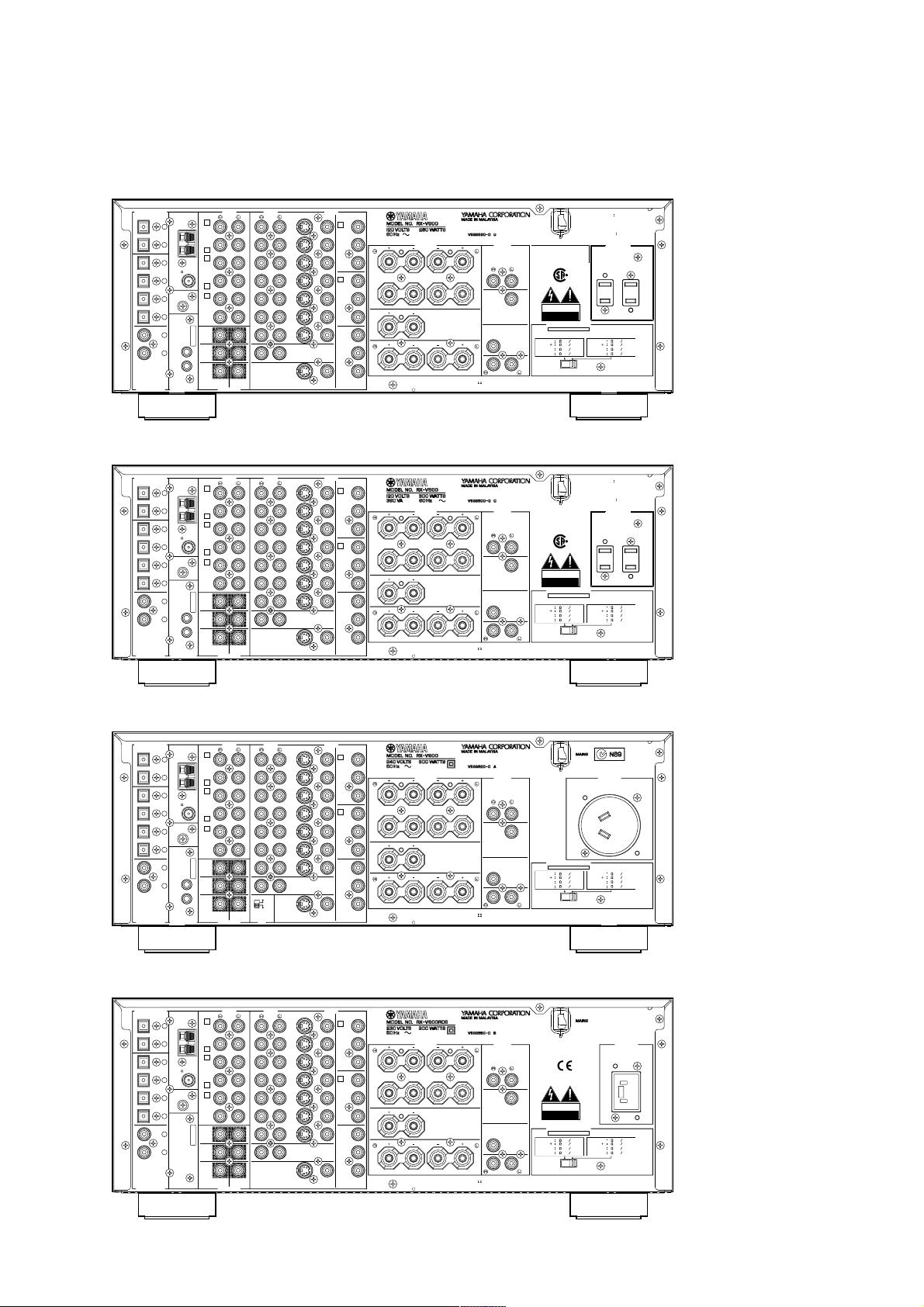
■ REAR PANELS
U model
C model
DIGITAL OUTPUT
DIGITAL OUTPUT
MD/
TAPE
CD-R
CD
CD-R
DVD
D-TV
/LD
CD
CBL
/SAT
MD/
TAPE
CD-R
CD
CD
CD-R
DVD
D-TV
/LD
CD
CBL
/SAT
OPTICAL
OPTICAL
COAXIAL
OPTICAL
OPTICAL
COAXIAL
1
AM
ANT
2
GND
3
FM
4
ANT
GND
5
6
7
IN
8
OUT
REMOTE CONTROL
1
AM
ANT
2
GND
3
FM
4
ANT
GND
5
6
7
IN
8
OUT
REMOTE CONTROL
TUNER
75
TUNER
75
AUDIO
3
IN
(PLAY)
MD/TAPE
OUT
(REC)
4
3
IN
(PLAY)
CD-R
UNBAL.
OUT
(REC)
4
1
CD
PHONO
MAIN
SURROUND
MONITOR
SUB
WOOFER
CENTER
6CH INPUTDIGITAL INPUT
AUDIO
3
IN
(PLAY)
MD/TAPE
OUT
(REC)
4
3
IN
(PLAY)
CD-R
UNBAL.
OUT
(REC)
4
1
CD
PHONO
MAIN
SURROUND
MONITOR
SUB
WOOFER
CENTER
6CH INPUTDIGITAL INPUT
DVD
D-TV
/LD
CBL
/SAT
IN
VDR 1
OUT
IN
VDR 2
/DVR
OUT
ZONE 2 OUT
OUT
DVD
D-TV
/LD
CBL
/SAT
IN
VDR 1
OUT
IN
VDR 2
/DVR
OUT
ZONE 2 OUT
OUT
S VIDEO
S VIDEO VIDEO
S VIDEO
S VIDEO VIDEO
VIDEOAUDIO
VIDEO
COMPONENT
DVD
A
Y
PB/
C
B
PR/
z
A
C
R
D-TV/LD
MAIN
B
Y
zz
B
PB/
C
B
CENTER
PR/
C
R
MONITOR
OUT
Y
PB/
C
B
PR/
C
R
REAR
(SURROUND)
VIDEOAUDIO
VIDEO
COMPONENT
DVD
A
Y
PB/
C
B
PR/
A
C
R
D-TV/LD
MAIN
B
Y
B
PB/
C
B
CENTER
PR/
C
R
MONITOR
OUT
Y
PB/
C
B
PR/
C
R
REAR
(SURROUND)
CLASS 2 WIRING
ATTENTION
CORRECT, SE REPORTER AU MANUEL
z
D'INSTRUCTIONS.
SEE INSTRUCTION
CAUTION
MANUAL FOR CORRECT SETTING.
zz
MANUFACTURED UNDER LICENSE FROM DOLBY LABORATORIES.
"DOLBY "," AC-3 "," PRO LOGIC ", AND THE DOUBLE-D SYMBOL
TRADEMARKS OF DOLBY LABORATORIES. CONFIDENTIAL UNPUBLISHED
C
I992-I997 DOLBY LABORATORIES. ALL RIGHTS RESERVED.
WORKS.
z
zz
CLASS 2 WIRING
ATTENTION
CORRECT, SE REPORTER AU MANUEL
z
D'INSTRUCTIONS.
SEE INSTRUCTION
CAUTION
MANUAL FOR CORRECT SETTING.
zz
MANUFACTURED UNDER LICENSE FROM DOLBY LABORATORIES.
"DOLBY "," AC-3 "," PRO LOGIC ", AND THE DOUBLE-D SYMBOL
TRADEMARKS OF DOLBY LABORATORIES. CONFIDENTIAL UNPUBLISHED
C
I992-I997 DOLBY LABORATORIES. ALL RIGHTS RESERVED.
WORKS.
z
POUR UN REGLAGE
z
POUR UN REGLAGE
CENTER
REAR (SURROUND)
ARE
CENTER
REAR (SURROUND)
ARE
OUTPUTSPEAKERS
THIS DEVICE COMPLIES WITH PART 15 OF
THE FCC RULES. OPERATIONIS SUBJECT TO
THE CONDITION THAT THIS DEVICE DOES
NOT CAUSE HARMFUL INTERFERENCE.
MAIN
US
CAUTION
SUB
WOOFER
RISK OF ELECTRIC SHOCK
DO NOT OPEN
IMPEDANCE SELECTOR
SET BEFORE POWER ON
MIN.
4
MAIN A OR B
MIN.
8
BA
CENTER
MIN.
6
MIN.
6
REAR
MANUFACTURED UNDER LICENSE FROM DIGITAL THEATER SYSTEMS, INC. US PAT.
NO.5,45I,942 AND OTHER WORLD-WIDE PATENTS ISSUED AND PENDING. "DTS",
"DTS DIGITAL SURROUND", ARE TRADEMARKS OF DIGITALTHEATER SYSTEMS, INC.
COPYRIGHT 1998 DIGITAL THEATER SYATEMS, INC, ALL RIGHTS RESERVED.
OUTPUTSPEAKERS
MAIN
CAUTION
SUB
WOOFER
RISK OF ELECTRIC SHOCK
DO NOT OPEN
IMPEDANCE SELECTOR
SET BEFORE POWER ON
SELECTEUR D'IMPEDANCE
MIN.
4
MAIN A OR B
MIN.
8
BA
CENTER
MIN.
6
MIN.
6
REAR
MANUFACTURED UNDER LICENSE FROM DIGITAL THEATER SYSTEMS, INC. US PAT.
NO.5,45I,942 AND OTHER WORLD-WIDE PATENTS ISSUED AND PENDING. "DTS",
"DTS DIGITAL SURROUND", ARE TRADEMARKS OF DIGITALTHEATER SYSTEMS, INC.
COPYRIGHT 1998 DIGITAL THEATER SYATEMS, INC, ALL RIGHTS RESERVED.
WARNING
OF FIRE OR ELECTRIC SHOCK,
DO NOT EXPOSE THIS APPLIANCE
TO RAIN OR MOISTURE.
ATTENTION
ELECTRIQUE NE PAS OUVRIR.
SPEAKER
MAIN A OR B
SPEAKER
CENTER
SPEAKER
SPEAKER
REAR
WARNING
OF FIRE OR ELECTRIC SHOCK,
DO NOT EXPOSE THIS APPLIANCE
TO RAIN OR MOISTURE.
ATTENTION
ELECTRIQUE NE PAS OUVRIR.
SPEAKER
MAIN A OR B
SPEAKER
CENTER
SPEAKER
SPEAKER
REAR
TO REDUCE THE RISK
RISQUE DE CHOC
AC OUTLETS
SWITCHED
I20V 60Hz
I00W MAX. TOTAL
MIN.
8
MIN.
I6
BA
MIN.
8
MIN.
8
TO REDUCE THE RISK
RISQUE DE CHOC
AC OUTLETS
SWITCHED
I20V 60Hz
I00W MAX. TOTAL
0.8A MAX TOTAL
MIN.
8
MIN.
I6
BA
MIN.
8
MIN.
8
SPEAKER
SPEAKER
SPEAKER
SPEAKER
SPEAKER
SPEAKER
SPEAKER
SPEAKER
A model
B model
DIGITAL OUTPUT
DIGITAL OUTPUT
MD/
TAPE
CD-R
CD
CD
CD-R
DVD
D-TV
/LD
CD
CBL
/SAT
MD/
TAPE
CD-R
CD
CD
CD-R
DVD
D-TV
/LD
CD
CBL
/SAT
OPTICAL
OPTICAL
COAXIAL
OPTICAL
OPTICAL
COAXIAL
1
AM
ANT
2
GND
3
FM
4
ANT
GND
5
6
7
IN
8
OUT
REMOTE CONTROL
1
AM
ANT
2
GND
3
FM
4
ANT
GND
5
6
7
8
TUNER
75
TUNER
75
AUDIO
3
IN
(PLAY)
MD/TAPE
OUT
(REC)
4
3
IN
(PLAY)
CD-R
UNBAL.
OUT
(REC)
4
1
CD
PHONO
MAIN
SURROUND
(PLAY)
MD/TAPE
(REC)
(PLAY)
CD-R
UNBAL.
(REC)
CD
PHONO
MAIN
SURROUND
I00KHZ/10KH
Z
MONITOR
50KHZ/9KH
Z
AM
FM
SUB
WOOFER
CENTER
FREQUENCY
6CH INPUTDIGITAL INPUT
STEP
AUDIO
3
IN
OUT
4
3
IN
OUT
4
1
MONITOR
SUB
WOOFER
CENTER
6CH INPUTDIGITAL INPUT
DVD
D-TV
/LD
CBL
/SAT
IN
VDR 1
OUT
IN
VDR 2
/DVR
OUT
ZONE 2 OUT
OUT
DVD
D-TV
/LD
CBL
/SAT
IN
VDR 1
OUT
IN
VDR 2
/DVR
OUT
ZONE 2 OUT
OUT
S VIDEO
S VIDEO
S VIDEO
S VIDEO VIDEO
VIDEOAUDIO
VIDEO
COMPONENT
DVD
A
Y
PB/
C
B
PR/
C
R
D-TV/LD
B
Y
PB/
C
B
PR/
C
R
MONITOR
OUT
Y
PB/
C
B
PR/
C
R
VIDEO
VIDEOAUDIO
VIDEO
COMPONENT
DVD
A
Y
PB/
C
B
PR/
C
R
D-TV/LD
B
Y
PB/
C
B
PR/
C
R
MONITOR
OUT
Y
PB/
C
B
PR/
C
R
SPEAKERS
z
A
MAIN
zz
B
CENTER
REAR
MAIN
CENTER
REAR
(SURROUND)
A
B
(SURROUND)
CLASS 2 WIRING
ATTENTION
CORRECT, SE REPORTER AU MANUEL
z
D'INSTRUCTIONS.
SEE INSTRUCTION
CAUTION
MANUAL FOR CORRECT SETTING.
zz
MANUFACTURED UNDER LICENSE FROM DOLBY LABORATORIES.
"DOLBY "," AC-3 "," PRO LOGIC ", AND THE DOUBLE-D SYMBOL
TRADEMARKS OF DOLBY LABORATORIES. CONFIDENTIAL UNPUBLISHED
C
I992-I997 DOLBY LABORATORIES. ALL RIGHTS RESERVED.
WORKS.
z
zz
CLASS 2 WIRING
ATTENTION
CORRECT, SE REPORTER AU MANUEL
z
D'INSTRUCTIONS.
SEE INSTRUCTION
CAUTION
MANUAL FOR CORRECT SETTING.
zz
MANUFACTURED UNDER LICENSE FROM DOLBY LABORATORIES.
"DOLBY "," AC-3 "," PRO LOGIC ", AND THE DOUBLE-D SYMBOL
TRADEMARKS OF DOLBY LABORATORIES. CONFIDENTIAL UNPUBLISHED
C
I992-I997 DOLBY LABORATORIES. ALL RIGHTS RESERVED.
WORKS.
z
POUR UN REGLAGE
z
POUR UN REGLAGE
CENTER
REAR (SURROUND)
ARE
CENTER
REAR (SURROUND)
ARE
OUTPUT
MAIN
SUB
WOOFER
IMPEDANCE SELECTOR
SET BEFORE POWER ON
MIN.
4
MAIN A OR B
MIN.
8
BA
CENTER
MIN.
6
MIN.
6
REAR
MANUFACTURED UNDER LICENSE FROM DIGITAL THEATER SYSTEMS, INC. US PAT.
NO.5,45I,942 AND OTHER WORLD-WIDE PATENTS ISSUED AND PENDING. "DTS",
"DTS DIGITAL SURROUND", ARE TRADEMARKS OF DIGITALTHEATER SYSTEMS, INC.
COPYRIGHT 1998 DIGITAL THEATER SYATEMS, INC, ALL RIGHTS RESERVED.
OUTPUTSPEAKERS
MAIN
CAUTION
SUB
WOOFER
RISK OF ELECTRIC SHOCK
DO NOT OPEN
IMPEDANCE SELECTOR
SET BEFORE POWER ON
MIN.
4
MAIN A OR B
MIN.
8
BA
CENTER
MIN.
6
MIN.
6
REAR
MANUFACTURED UNDER LICENSE FROM DIGITAL THEATER SYSTEMS, INC. US PAT.
NO.5,45I,942 AND OTHER WORLD-WIDE PATENTS ISSUED AND PENDING. "DTS",
"DTS DIGITAL SURROUND", ARE TRADEMARKS OF DIGITALTHEATER SYSTEMS, INC.
COPYRIGHT 1998 DIGITAL THEATER SYATEMS, INC, ALL RIGHTS RESERVED.
SPEAKER
SPEAKER
SPEAKER
SPEAKER
SPEAKER
SPEAKER
SPEAKER
SPEAKER
MAIN A OR B
CENTER
REAR
MAIN A OR B
CENTER
REAR
AC OUTLET
SWITCHED
I00W MAX.
BA
BA
SPEAKER
MIN.
8
SPEAKER
MIN.
I6
SPEAKER
MIN.
8
SPEAKER
MIN.
8
AC OUTLET
SWITCHED
I00W MAX.
SPEAKER
MIN.
8
SPEAKER
MIN.
I6
SPEAKER
MIN.
8
SPEAKER
MIN.
8
5
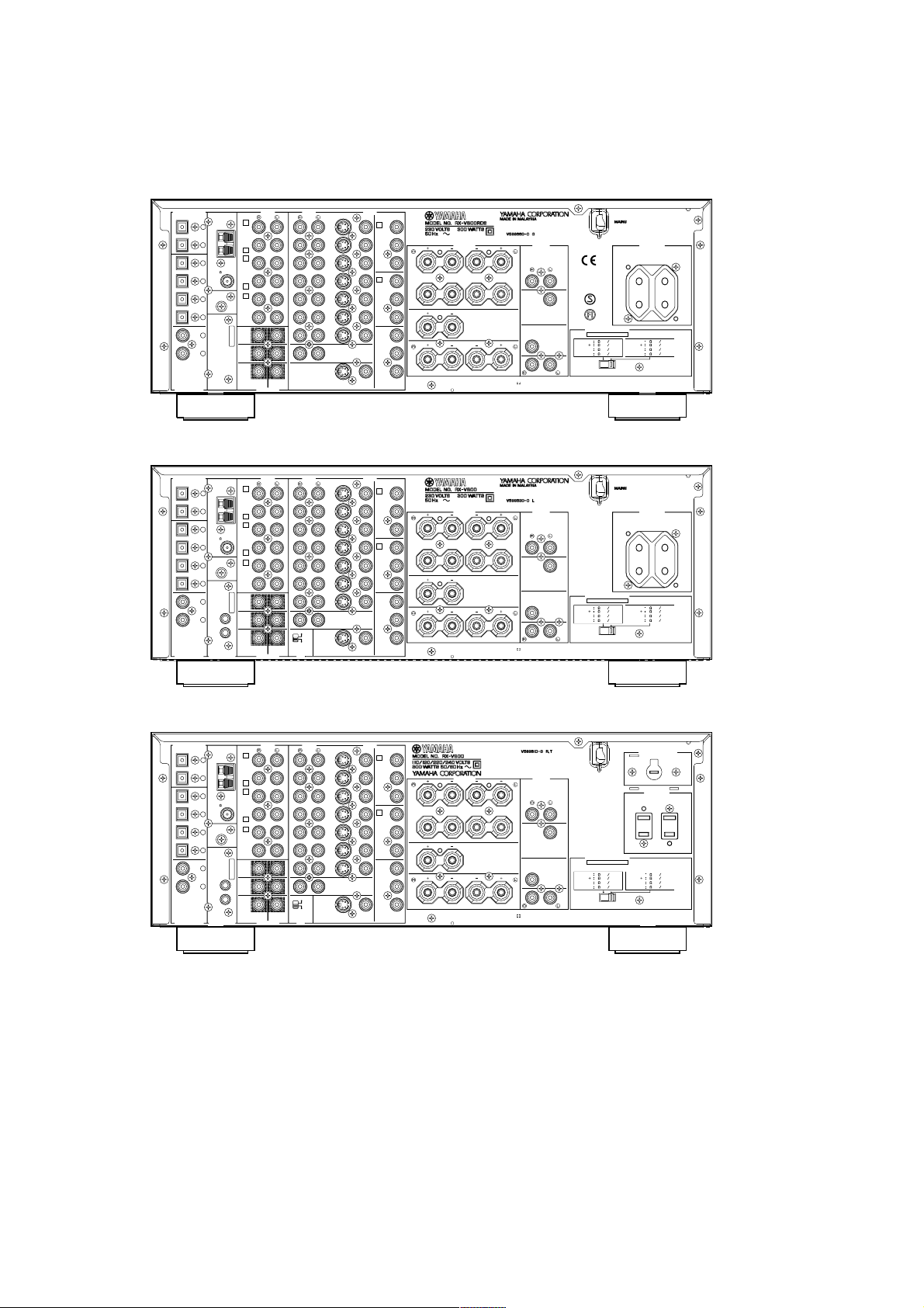
G model
RX-V800/RX-V800RDS/HTR-5280
L model
DIGITAL OUTPUT
DIGITAL OUTPUT
TAPE
CD-R
CD-R
/SAT
TAPE
CD-R
CD-R
/SAT
MD/
CD
CD
DVD
D-TV
/LD
CD
CBL
MD/
CD
CD
DVD
D-TV
/LD
CD
CBL
OPTICAL
OPTICAL
COAXIAL
OPTICAL
OPTICAL
COAXIAL
1
AM
ANT
2
GND
3
75
FM
4
ANT
GND
5
6
7
8
1
AM
ANT
2
GND
3
75
FM
4
ANT
GND
5
6
7
IN
8
OUT
REMOTE CONTROL
OUT
OUT
DVD
D-TV
/LD
CBL
/SAT
IN
VDR 1
OUT
IN
VDR 2
/DVR
OUT
ZONE 2 OUT
DVD
D-TV
/LD
CBL
/SAT
IN
VDR 1
OUT
IN
VDR 2
/DVR
OUT
ZONE 2 OUT
S VIDEO
S VIDEO VIDEO
S VIDEO
S VIDEO
VIDEOAUDIO
VIDEO
COMPONENT
DVD
A
Y
PB/
C
B
PR/
z
A
C
R
D-TV/LD
MAIN
B
Y
zz
B
PB/
C
B
CENTER
PR/
C
R
MONITOR
OUT
Y
PB/
C
B
PR/
C
R
REAR
(SURROUND)
VIDEOAUDIO
VIDEO
COMPONENT
DVD
A
Y
PB/
C
B
PR/
A
C
R
D-TV/LD
MAIN
B
Y
B
PB/
C
B
CENTER
PR/
C
R
MONITOR
OUT
Y
PB/
C
B
PR/
C
R
REAR
VIDEO
(SURROUND)
CLASS 2 WIRING
ATTENTION
CORRECT, SE REPORTER AU MANUEL
z
D'INSTRUCTIONS.
SEE INSTRUCTION
CAUTION
MANUAL FOR CORRECT SETTING.
zz
MANUFACTURED UNDER LICENSE FROM DOLBY LABORATORIES.
"DOLBY "," AC-3 "," PRO LOGIC ", AND THE DOUBLE-D SYMBOL
TRADEMARKS OF DOLBY LABORATORIES. CONFIDENTIAL UNPUBLISHED
C
I992-I997 DOLBY LABORATORIES. ALL RIGHTS RESERVED.
WORKS.
z
zz
CLASS 2 WIRING
ATTENTION
CORRECT, SE REPORTER AU MANUEL
z
D'INSTRUCTIONS.
SEE INSTRUCTION
CAUTION
MANUAL FOR CORRECT SETTING.
zz
MANUFACTURED UNDER LICENSE FROM DOLBY LABORATORIES.
"DOLBY "," AC-3 "," PRO LOGIC ", AND THE DOUBLE-D SYMBOL
TRADEMARKS OF DOLBY LABORATORIES. CONFIDENTIAL UNPUBLISHED
C
I992-I997 DOLBY LABORATORIES. ALL RIGHTS RESERVED.
WORKS.
z
POUR UN REGLAGE
z
POUR UN REGLAGE
CENTER
REAR (SURROUND)
ARE
CENTER
REAR (SURROUND)
ARE
OUTPUTSPEAKERS
MAIN
SUB
WOOFER
IMPEDANCE SELECTOR
SET BEFORE POWER ON
MIN.
4
MAIN A OR B
MIN.
8
BA
CENTER
MIN.
6
MIN.
6
REAR
MANUFACTURED UNDER LICENSE FROM DIGITAL THEATER SYSTEMS, INC. US PAT.
NO.5,45I,942 AND OTHER WORLD-WIDE PATENTS ISSUED AND PENDING. "DTS",
"DTS DIGITAL SURROUND", ARE TRADEMARKS OF DIGITALTHEATER SYSTEMS, INC.
COPYRIGHT 1998 DIGITAL THEATER SYATEMS, INC, ALL RIGHTS RESERVED.
SPEAKER
SPEAKER
SPEAKER
SPEAKER
SPEAKER
SPEAKER
SPEAKER
SPEAKER
I00W MAX. TOTAL
MAIN A OR B
CENTER
REAR
I00W MAX. TOTAL
MAIN A OR B
CENTER
REAR
AC OUTLETS
SWITCHED
8
I6
BA
8
8
AC OUTLETS
SWITCHED
8
I6
BA
8
8
SPEAKER
MIN.
SPEAKER
MIN.
SPEAKER
MIN.
SPEAKER
MIN.
SPEAKER
MIN.
SPEAKER
MIN.
SPEAKER
MIN.
SPEAKER
MIN.
AUDIO
TUNER
3
IN
(PLAY)
MD/TAPE
OUT
(REC)
4
3
IN
(PLAY)
CD-R
UNBAL.
OUT
(REC)
4
1
CD
PHONO
MAIN
SURROUND
MONITOR
SUB
WOOFER
CENTER
6CH INPUTDIGITAL INPUT
AUDIO
TUNER
3
IN
(PLAY)
MD/TAPE
OUT
(REC)
4
3
IN
(PLAY)
CD-R
UNBAL.
OUT
(REC)
4
1
CD
PHONO
MAIN
SURROUND
CENTER
I00KHZ/10KH
Z
MONITOR
50KHZ/9KH
Z
AM
FM
SUB
WOOFER
FREQUENCY
6CH INPUTDIGITAL INPUT
STEP
R, T model
DIGITAL OUTPUT
TAPE
CD-R
CD-R
/SAT
MD/
CD
DVD
D-TV
/LD
CD
CBL
OPTICAL
OPTICAL
COAXIAL
1
AM
ANT
2
GND
3
75
FM
4
ANT
GND
5
6
7
IN
8
OUT
REMOTE CONTROL
OUT
DVD
D-TV
/LD
CBL
/SAT
IN
VDR 1
OUT
IN
VDR 2
/DVR
OUT
ZONE 2 OUT
S VIDEO
S VIDEO
VIDEOAUDIO
VIDEO
COMPONENT
DVD
A
Y
PB/
C
B
PR/
z
A
C
R
D-TV/LD
MAIN
B
Y
zz
B
PB/
C
B
CENTER
PR/
C
R
MONITOR
OUT
Y
PB/
C
B
PR/
C
R
REAR
VIDEO
(SURROUND)
CLASS 2 WIRING
ATTENTION
CORRECT, SE REPORTER AU MANUEL
z
D'INSTRUCTIONS.
SEE INSTRUCTION
CAUTION
MANUAL FOR CORRECT SETTING.
zz
MANUFACTURED UNDER LICENSE FROM DOLBY LABORATORIES.
"DOLBY "," AC-3 "," PRO LOGIC ", AND THE DOUBLE-D SYMBOL
TRADEMARKS OF DOLBY LABORATORIES. CONFIDENTIAL UNPUBLISHED
C
I992-I997 DOLBY LABORATORIES. ALL RIGHTS RESERVED.
WORKS.
z
POUR UN REGLAGE
CENTER
REAR (SURROUND)
ARE
OUTPUTSPEAKERS
MAIN
SUB
WOOFER
IMPEDANCE SELECTOR
SET BEFORE POWER ON
MAIN A OR B
BA
CENTER
REAR
MANUFACTURED UNDER LICENSE FROM DIGITAL THEATER SYSTEMS, INC. US PAT.
NO.5,45I,942 AND OTHER WORLD-WIDE PATENTS ISSUED AND PENDING. "DTS",
"DTS DIGITAL SURROUND", ARE TRADEMARKS OF DIGITALTHEATER SYSTEMS, INC.
COPYRIGHT 1998 DIGITAL THEATER SYATEMS, INC, ALL RIGHTS RESERVED.
VOLTAGE SELECTOR
AC OUTLETS
SWITCHED
I00W MAX. TOTAL
SPEAKER
MIN.
4
SPEAKER
MIN.
8
SPEAKER
MIN.
6
SPEAKER
MIN.
6
MAIN A OR B
CENTER
REAR
SPEAKER
MIN.
8
SPEAKER
MIN.
I6
BA
SPEAKER
MIN.
8
SPEAKER
MIN.
8
AUDIO
TUNER
3
IN
(PLAY)
MD/TAPE
OUT
(REC)
4
3
IN
(PLAY)
CD-R
UNBAL.
OUT
(REC)
4
1
CD
PHONO
MAIN
SURROUND
CENTER
I00KHZ/10KH
Z
MONITOR
50KHZ/9KH
Z
AM
FM
SUB
WOOFER
FREQUENCY
6CH INPUTDIGITAL INPUT
STEP
6

RX-V800/RX-V800RDS/HTR-5280
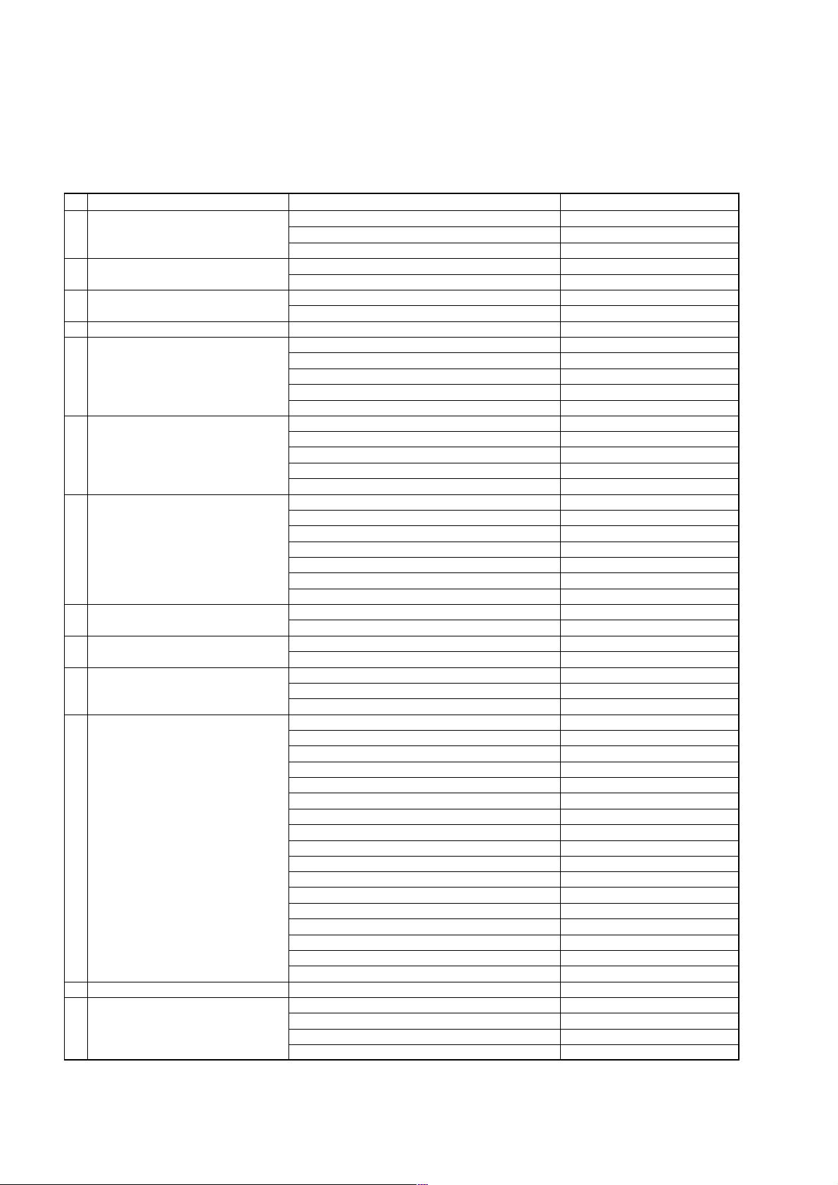
■ INTERNAL VIEW
123 4 5 6 87 9
L A
K
J
I
0
B
1 POWER (3) P.C.B.
2 MAIN (5) P.C.B.
3 MAIN (2) P.C.B.
4 VIDEO (3) P.C.B.
5 VIDEO (2) P.C.B.
6 VIDEO (1) P.C.B.
7 POWER (7) P.C.B.
8 POWER (8) P.C.B.
9 POWER (9) P.C.B.
0 POWER (10) P.C.B.
A DSP P.C.B.
B FUNCTION P.C.B.
C OPERATION (5) P.C.B.
D OPERATION (4) P.C.B.
E MAIN (1) P.C.B.
F POWER (6) P.C.B.
G POWER (5) P.C.B.
H POWER (4) P.C.B.
I POWER (2) P.C.B.
J MAIN (4) P.C.B.
CDEFHG
K MAIN (3) P.C.B.
L POWER (1) P.C.B.
7
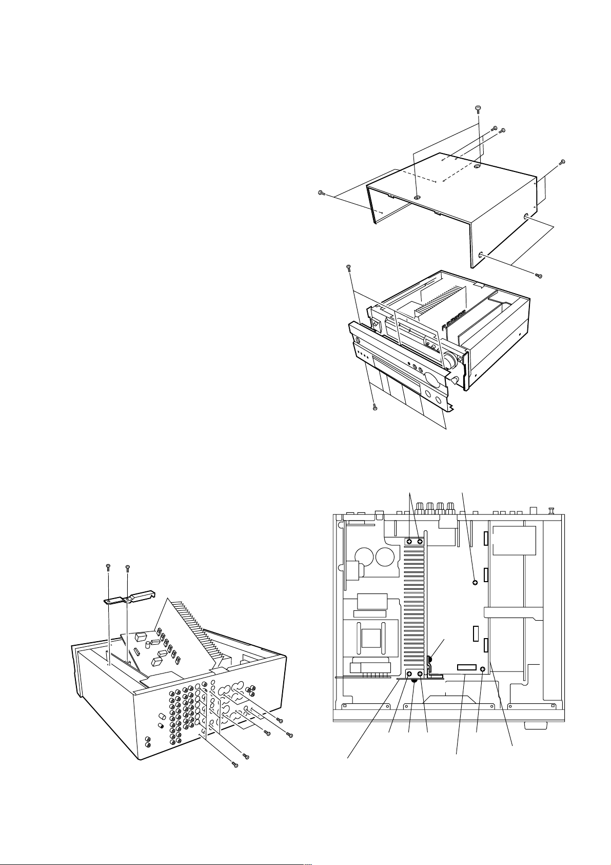
■ DISASSEMBLY PROCEDURES
(Remove parts in the order as numbered.)
Disconnect the power cord from the AC outlet.
RX-V800/RX-V800RDS/HTR-5280
1
3
3
1. Removal of Top Cover
a. Remove 2 screws (1), 4 screws (2) and 5 screws (3)
in Fig. 1.
b. Slide the Top Cover rearward to remove it.
2. Removal of Front Panel
Remove 9 screws (4) in Fig. 1, and the Front Panel
can be removed forward.
3. Removal of MAIN PCB (1)
a. Remove the Top Cover.
b. Remove 2 screws (5 ) in Fig. 3 AND remove the
support metal plate.
c. Disconnect 3 connectors (CB232, CB601, CB602 in
Fig.2) from the VIDEO PCB (1), and disconnect the
connector (CB3) from the MAIN PCB (1) in Fig. 2.
d. Remove 8 screws (6) in Fig. 3, and the VIDEO PCB (1)
and VIDEO PCB (3) can be removed.
e. Disconnect the connector (CB353) from the POWER
PCB (6) in Fig. 2.
f. Remove the plastic rivet 7, and the POWER PCB (6)
can be removed upward from the heat sink.
g. Disconnect the connector (CB1 in Fig. 2) from the MAIN
PCB (1) .
h. Remove 2 screws (8) in Fig. 2, and the support
Transistor can be removed.
i. Remove 6 screws (9) in Fig. 2.
j. Remove 6 screws (0) in Fig. 3.
k. Pull out the MAIN PCB (1) forward as shown in Fig. 3.
At this time, disconnect the flexible flat cable connected
to the MAIN PCB (1) if necessary.
3
2
4
2
4
Fig. 1
99
5
5
Fig. 3
6
6
0
0
0
POWER (6) PCB
8
CB353
799
MAIN (1) PCB
Fig. 2
CB601
CB602
CB3
CB232
CB1
9
VIDEO (1) PCB
8
RX-V800/RX-V800RDS/HTR-5280
■ SELF DIAGNOSIS FUNCTION (DIAG)
There are 13 DIAG menu items each of which has sub-menu items. Listed in the table below are menu items and sub-menu
items.
No. DIAG menu sub-menu Remote control code (key)
1 DSP THROUGH 1. ANALOG BYPAS (ANALOG BYPASS) 7A-90 (PRG 9)
2. DSP 0dB 7A-91 (PRG 10)
3. DSP FULL BIT 7A-92 (PRG 11)
2 HP ROUTE 1. HP 0dB 7A-93 (PRG 12)
2. HP FULL BIT 7A-10 (PRESET+)
3 RAM THROUGH 1. RAM 0dB 7A-11 (PRESET-)
2. MAIN ATT 7A-12 (PAGE)
4 PRO LOGIC 1. YSS928 7A-0C (CD FF)
5 SPEAKERS SET 1. MAIN:SML 0dB (MAIN:SMALL 0dB) 7A-88 (PRG 1)
2. MAIN:LRG -10dB (MAIN:LARGE -10dB) 7A-89 (PRG 2)
3. CENTER:NONE 7A-8A (PRG 3)
4. LFE/B:MAIN (LFE/BASS:MAIN) 7A-8B (PRG 4)
5. Front Mix:5ch 7A-8C (PRG 5)
6 DISPLAY CHECK 1. VFD CHECK (initial screen) 7A-8F (PRG 8)
2. VFD DISP OFF (All segments OFF) –
3. VFD DISP ALL (All segments ON 100%) –
4. VFD DIMMER (All segments ON 50%) –
5. CHECKED PATTERN (ON in lattice) –
7 MANUAL TEST 1. ALL 7A-00 (TP PLAY)
2. MAIN L 7A-01 (TP RW)
3. CENTER 7A-02 (TP FW)
4. MAIN R 7A-03 (TP STOP)
5. REAR R 7A-04 (TP PAUSE)
6. REAR L 7A-06 (TP A/B)
7. LFE 7A-09 (CD STOP)
8 RS-232C 1. TxRx DATA (unused) –
2. HARD FLOW (unused) –
9 PRESET 1.
10 AD DATA CHECK 1. REC-OUT (unused) –
11 IF STATUS 1. IST (internal status) –
12 DSP RAM CHECK Bus Check 7A-0A (CD SKIP+)
13 VERSION/CHECK SUM/PORT 1. VER. (Version information) 7A-0D (CD REW)
PRESET INHIBIT (memory initialization inhibited)
2. PRESET RESERVED (memory initialized) 7A-57 (SLEEP)
2. K0/K1 (panel key) –
3. DC/PS (protection) 7A-0B (CD SKIP-)
2. CS1 (channel status 1) –
3. CS2 (channel status 2) –
4. CS3 (channel status 3) –
5. CS4 (channel status 4) –
6. CS5 (channel status 5) –
7. BI1 (BSI-DD 1) –
8. BI2 (BSI-DD 2) –
9. BI3 (BSI-DD 3) –
10. BI4 (BSI-DD 4) –
11. BS1 (BSI-DTS 1) –
12. BS2 (BSI-DTS 2) –
13. BS3 (BSI-DTS 3) –
14. BS4 (BSI-DTS 4) –
15. YS1 (YSS-928-1) –
16. YS2 (YSS-928-2) –
17. YS3 (YSS-928-3) –
2. A/P (Checksum ALL/PROG) –
3. 2/M (Checksum 232C/MAKER) –
4. PORT (Port check) –
–
9
• Starting DIAG
ł
ł
ł
ł
Press the “STANDBY/ON key while pressing those two keys indicated in the
figure on the right.
RX-V800/RX-V800RDS/HTR-5280
• Starting DIAG in the protection cancel mode
If the protection function works and causes hindrance to trouble diagnosis, cancel
the protection function as described below, and it will be possible to enter the
DIAG mode. (The protection function other than the excess current detect
function will be cancelled.)
Press the “STANDBY/ON key while pressing those two keys indicated in the
figure on the right. At this time, keep pressing those two keys for 3 seconds or
longer.
In this mode, the “ZONE2” segment of the FL display of the main unit flashes to indicate that the mode is DIAG mode with the
protection functions cancelled.
Keys of main unit (in sealing panel)
A/B/C/D/E
Turn on the power while
pressing these keys.
PRESET/
TUNING
CAUTION!
Note that during the DIAG mode with protection functions cancelled, even when a danger is encountered, protection
functions do not work. Therefore, operating the equipment in this mode may cause danger to it. Use special care for this
point when using this mode.
• Canceling DIAG
[1] Before canceling DIAG, execute setting for PRESET of DIAG menu No.9 (Memory initialization inhibited or Memory
initialized).
* In order to keep the user memory stored, be sure to select PRESET INHI (Memory initialization inhibited).
[2] Turn off the power by pressing the “STANDBY/ON” key of the main unit or the “STANDBY” key of the remote controller.
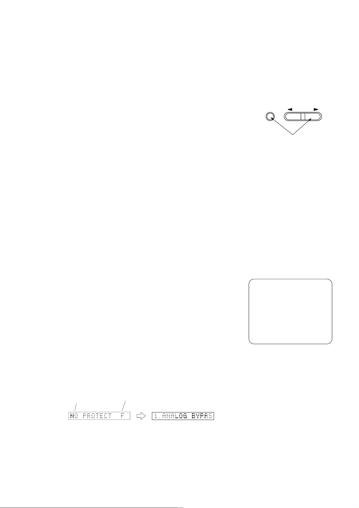
• Display provided when DIAG started
When the monitor is connected, DIAGNOSTIC MENU appears on its screen as
shown in the figure. (It remains on display until DIAG is cancelled.)
The FL display of the main unit displays the protection function history data and the version (1 alphabet) and the DIAG menu
(sub-menu (ANALOG BYPASS) of DIAG menu No.1 DSP THROUGH) a few seconds later.
When there is no history of protection function:
Opening message DIAG menu display
When there is no history
of protection function
Version (1 alphabet)
After a few seconds
y
łı
øı
œı
ßı
ı
ı
ı
10
RX-V800/RX-V800RDS/HTR-5280
PROGRAM
PRESET/
TUNING
DIAG menu selection
SUB-MENU selection
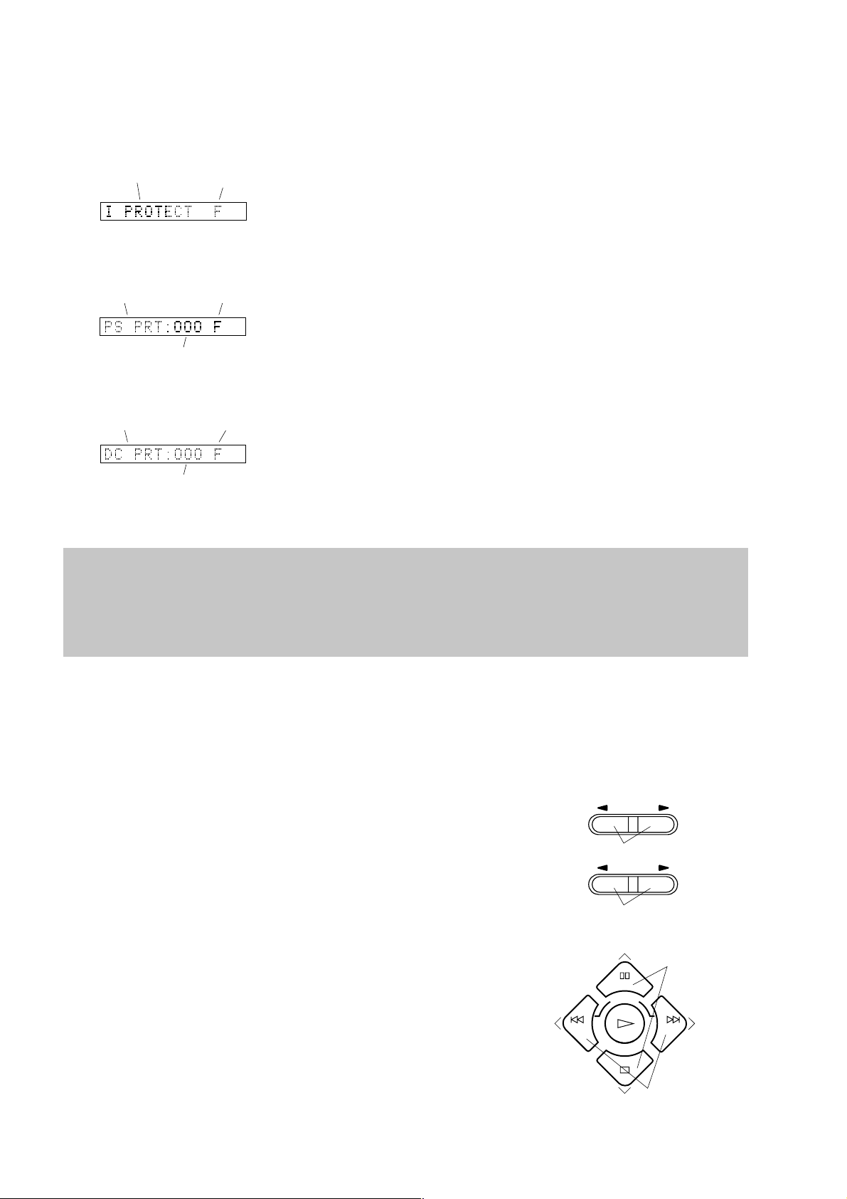
When there is a history of protection function:
When there is a history of
protection function against
excess current
When there is a history of
protection function against
abnormal voltage in the
power supply section
Voltage display in %
Version
(1 alphabet)
Version
(1 alphabet)
Cause: An excessive current flowed to the power amplifier.
Supplementary information: As current of the power transistor is detected, the
abnormal channel can be identified by checking the current detect transistor.
Turning on the power without correcting the abnormality will cause the protection
function to work immediately and the power supply will soon be shut off.
Cause: The voltage in the power supply section is abnormal.
Supplementary information: The abnormal voltage is displayed in % based on
5V as 100%.
Turning on the power without correcting the abnormality will cause the protection
function to work 1 second later and the power supply will be shut off.
When there is a history of
protection function against
abnormal DC output
Version
(1 alphabet)
Cause: DC output of the power amplifier is abnormal.
Supplementary information: The abnormal voltage is displayed in % based on
5V as 100%.
Turning on the power without correcting the abnormality will cause the protection
function to work 3 seconds later and the power supply will be shut off.
Voltage display in %
* Besides above possible causes for abnormality, a cause may lie in disconnected connector, around CPU, etc.
* For the protection voltage value, refer to DIAG menu No.10 described later.
• History of protection function
When the protection function has worked, its history is stored in memory with a backup. Even if no abnormality is noted
while servicing the unit, an abnormality which has occurred previously can be defined as long as the backup data has
been stored.
The history of the protection function is cleared when DIAG is cancelled by selecting RESERVED (Memory initialized) of
DIAG menu No.9 or when the backup data is erased.
• Display during menu operation
During the DIAG operation, the menu list described in the section of the startup screen appears on the superimposed screen
and the function at work is indicated on the FL indicator. The contents displayed during the function operation are described
in the later section on details of functions.
• Operation procedure of DIAG menu and SUB-MENU
There are No.1 to No.13 MENU items, each of which has some SUB-MENU
items.
DIAG menu selection
Main unit: Select the menu using • (Forward) and ¶ (Reverse) keys of
PRESET/TUNIG located in the sealing panel.
Remote control unit: Select the menu using ▲ (Forward) and ▼ (Reverse)keys.
SUB-MENU selection
Main unit: Select the sub-menu using • (Forward) and ¶ (Reverse) keys of
PROGRAM located in the sealing panel.
Remote control unit: Select the sub-menu using • (Forward) and 
(Reverse)keys.
* Only the remote control keys indicated in the MENU List can be used to select
a sub-menu directly.
11
Use these keys for
DIAG menu selection.
E
S
D
E
O
T
C
DIR A DIR B
O
SELECT
N
S
N
E
E
C
R
Use these keys for
SUB-MENU selection.

RX-V800/RX-V800RDS/HTR-5280
• Functions in DIAG mode
In addition to the DIAG menu items, functions as listed below are available.
• Input selection, 6CH input
• REC OUT (ZONE2) switching
• Center/Rear/Sub-woofer level adjustment
• Muting
• Speaker relay A/B
• Power on/off
• Master volume
It is possible to set to the following volume values directly by transmitting remote control codes during the DIAG operation
only.
Volume value (dB) Remove control Remote control
0 7A-E0 PAGE A
-20 7A-E1 PAGE B
-30 7A-E2 PAGE C
MUTE 7A-E3 PAGE D
code key
* Functions related to the tuner and the set menu are not available.
* It is possible to confirm Menu No.11 IF STATUS while keeping the signal process (operation status) of each DIAG menu
by using the input mode key of the main unit.
• Initial settings used to start DIAG
Following initial settings are used when starting DIAG.
When DIAG is canceled, these settings are restored to those before starting DIAG.
• Master volume: -40dB
• Input, ZONE2 input: DVD (6CH INPUT OFF)
• Center/Rear/Sub-woofer level: 0dB
• Audio mute: OFF
• Speaker relay A/B: ON
• Speaker setting: LARGE / BASS OUT = BOTH
• DIAG menu: DSP through (analog bypass)
12
RX-V800/RX-V800RDS/HTR-5280
• Details of DIAG menu
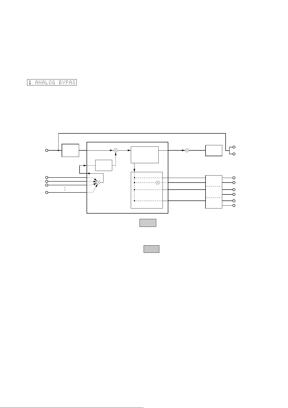
1. DSP THROUGH
There are 3 sub-menu items (ANALOG BYPAS, DSP 0dB, DSP FULL BIT).
ANALOG BYPASS [Remote control code: 7A-90 (PRG9)]
• The input mode is fixed to use the analog (A/D) system.
• The L/R signal is output through the analog bypass without using the DSP
block.
• C/SWF, FL/FR, RL/RR signals are output through DSP (see the signal path in
the figure below) without using the external DRAM. (Head margin included)
Head margin:
Center: -6dBFS, Rear Center: -3dBFS, FL/FR: -6dBFS, RL/RR: -12dBFS,
SWFR: Add L/R signal at -20dBFS.
ANALOG
DIGITAL
CODEC
(A/D)
AK4527
Main DSP
(Decoder)
INTERNAL
DIR
AC3D3 YSS928
L/R
L/R
L/R
L/R
L/R
Sub DSP
4M DRAM
SDOxx represents a terminal name of AC3D3.
The shaded square (
) means that the element indicated in it does not
operate.
L/R SDOA0
SDOB1
SDOB2
SDOB3
D/A
AK4393
CODEC
(D/A)
AK4527
L
R
C
SWFR
FL
FR
RL
RR
13
 Loading...