

Yamaha RXV-771 Service Manual

AV RECEIVER
RX-V771
SERVICE MANUAL
When the DIGITAL P.C.B. or IC83 on DIGITAL P.C.B. is replaced, the network function of this unit will not operate
Note:
properly without additional setting.
In such a case, report the serial number of this unit to the following e-mail address.
Yamaha Corporation will reply providing the setting procedure to make the network function of this unit operate
properly.
DIGITALP.C.B. または DIGITALP.C.B. の IC83 を交換すると本機のネットワーク機能が正常に動作しなくなり、正常
注意:
動作のための追加設定が必要になります。
そのような場合には本機のシリアルナンバーを下記の E メールアドレスへご連絡ください。
折り返し、ネットワーク機能が正常に動作するための追加設定方法をご連絡します。
E-mail: ycav-ysiss@gmx.yamaha.com
This manual has been provided for the use of authorized YAMAHA Retailers and their service personnel.
It has been assumed that basic service procedures inherent to the industry, and more specifi cally YAMAHA Products, are already known
and understood by the users, and have therefore not been restated.
WARNING:
IMPORTANT:
The data provided is believed to be accurate and applicable to the unit(s) indicated on the cover. The research, engineering, and service
departments of YAMAHA are continually striving to improve YAMAHA products. Modifications are, therefore, inevitable and
specifi cations are subject to change without notice or obligation to retrofi t. Should any discrepancy appear to exist, please contact the
distributor's Service Division.
WARNING:
IMPORTANT:
Failure to follow appropriate service and safety procedures when servicing this product may result in personal injury,
destruction of expensive components, and failure of the product to perform as specifi ed. For these reasons, we advise
all YAMAHA product owners that any service required should be performed by an authorized YAMAHA Retailer or
the appointed service representative.
The presentation or sale of this manual to any individual or fi rm does not constitute authorization, certifi cation or
recognition of any applicable technical capabilities, or establish a principle-agent relationship of any form.
Static discharges can destroy expensive components. Discharge any static electricity your body may have
accumulated by grounding yourself to the ground buss in the unit (heavy gauge black wires connect to this buss).
Turn the unit OFF during disassembly and part replacement. Recheck all work before you apply power to the unit.
■ CONTENTS
TO SERVICE PERSONNEL ............................................2
FRONT PANEL ...............................................................3
REAR PANELS ...........................................................3–5
REMOTE CONTROL PANELS .......................................6
SPECIFICATIONS /
INTERNAL VIEW .......................................................... 13
SERVICE PRECAUTIONS /
DISASSEMBLY PROCEDURES /
UPDATING FIRMWARE /
ファームウェアのアップデート
SELF-DIAGNOSTIC FUNCTION /
ダイアグ(自己診断機能)
参考仕様
...................................7–12
サービス時の注意事項
分解手順
............................ 17–18
..................................... 19–61
........... 14–16
.....13
IMPORTANT NOTICE
POWER AMPLIFIER ADJUSTMENT /
パワーアンプ調整
DISPLAY DATA .......................................................63–64
IC DATA ...................................................................65–77
PIN CONNECTION DIAGRAMS .............................78–80
BLOCK DIAGRAMS ................................................81–85
PRINTED CIRCUIT BOARDS ...............................86–105
SCHEMATIC DIAGRAMS ................................... 107–121
REPLACEMENT PARTS LIST ............................ 123–143
REMOTE CONTROL ........................................... 144–146
CONFIGURING THE SYSTEM SETTINGS .................147
システム設定を変更する
.......................................................62
............................................. 148
RX-V771
101215
Copyright © 2011 All rights reserved.
This manual is copyrighted by YAMAHA and may not be copied or
redistributed either in print or electronically without permission.
P.O.Box 1, Hamamatsu, Japan
'11.06

RX-V771
■ TO SERVICE PERSONNEL
1. Critical Components Information
Components having special characteristics are marked ⚠ and
must be replaced with parts having specifications equal to those
originally installed.
2. Leakage Current Measurement (For 120V Models Only)
When service has been completed, it is imperative to verify
that all exposed conductive surfaces are properly insulated
from supply circuits.
• Meter impedance should be equivalent to 1500 ohms shunted
by 0.15 μF.
WALL
OUTLET
• Leakage current must not exceed 0.5mA.
• Be sure to test for leakage with the AC plug in both polarities.
EQUIPMENT
UNDER TEST
INSULATING
TABLE
AC LEAKAGE
TESTER OR
EQUIVALENT
WARNING: CHEMICAL CONTENT NOTICE!
This product contains chemicals known to the State of California to cause cancer, or birth defects or other reproductive
harm.
DO NOT PLACE SOLDER, ELECTRICAL/ELECTRONIC OR PLASTIC COMPONENTS IN YOUR MOUTH FOR ANY REASON
WHATSOEVER!
Avoid prolonged, unprotected contact between solder and your skin! When soldering, do not inhale solder fumes or
expose eyes to solder/flux vapor!
If you come in contact with solder or components located inside the enclosure of this product, wash your hands before
handling food.
RX-V771
About lead free solder /
無鉛ハンダについて
All of the P.C.B.s installed in this unit and solder joints are
soldered using the lead free solder.
Among some types of lead free solder currently available,
it is recommended to use one of the following types for
the repair work.
• Sn + Ag + Cu (tin + silver + copper)
• Sn + Cu (tin + copper)
• Sn + Zn + Bi (tin + zinc + bismuth)
Caution:
As the melting point temperature of the lead free solder
is about 30°C to 40°C (50°F to 70°F) higher than that of
the lead solder, be sure to use a soldering iron suitable
to each solder.
本機に搭載されているすべての基板およびハンダ付けに
よる接合部は無鉛ハンダでハンダ付けされています。
無鉛ハンダにはいくつかの種類がありますが、修理時に
は下記のような無鉛ハンダの使用を推奨します。
Sn+Ag+Cu(錫+銀+銅)
Sn+Cu(錫 + 銅)
Sn+Zn+Bi(錫 + 亜鉛 + ビスマス)
注意:
無鉛ハンダの融点温度は通常の鉛入りハンダに比べ 30 〜
40℃程度高くなっていますので、それぞれのハンダに合っ
たハンダごてをご使用ください。
2
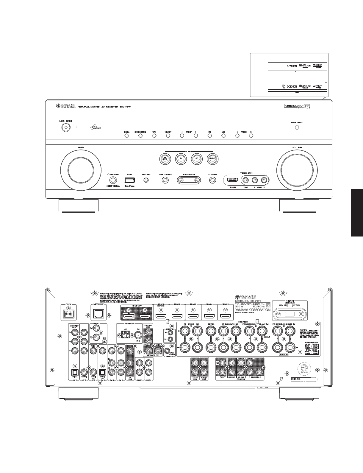
■ FRONT PANEL
R, T, K, A, B, G, F, L, H, J models
RX-V771
R, T, K, A, B, G, F, L, H models
J model
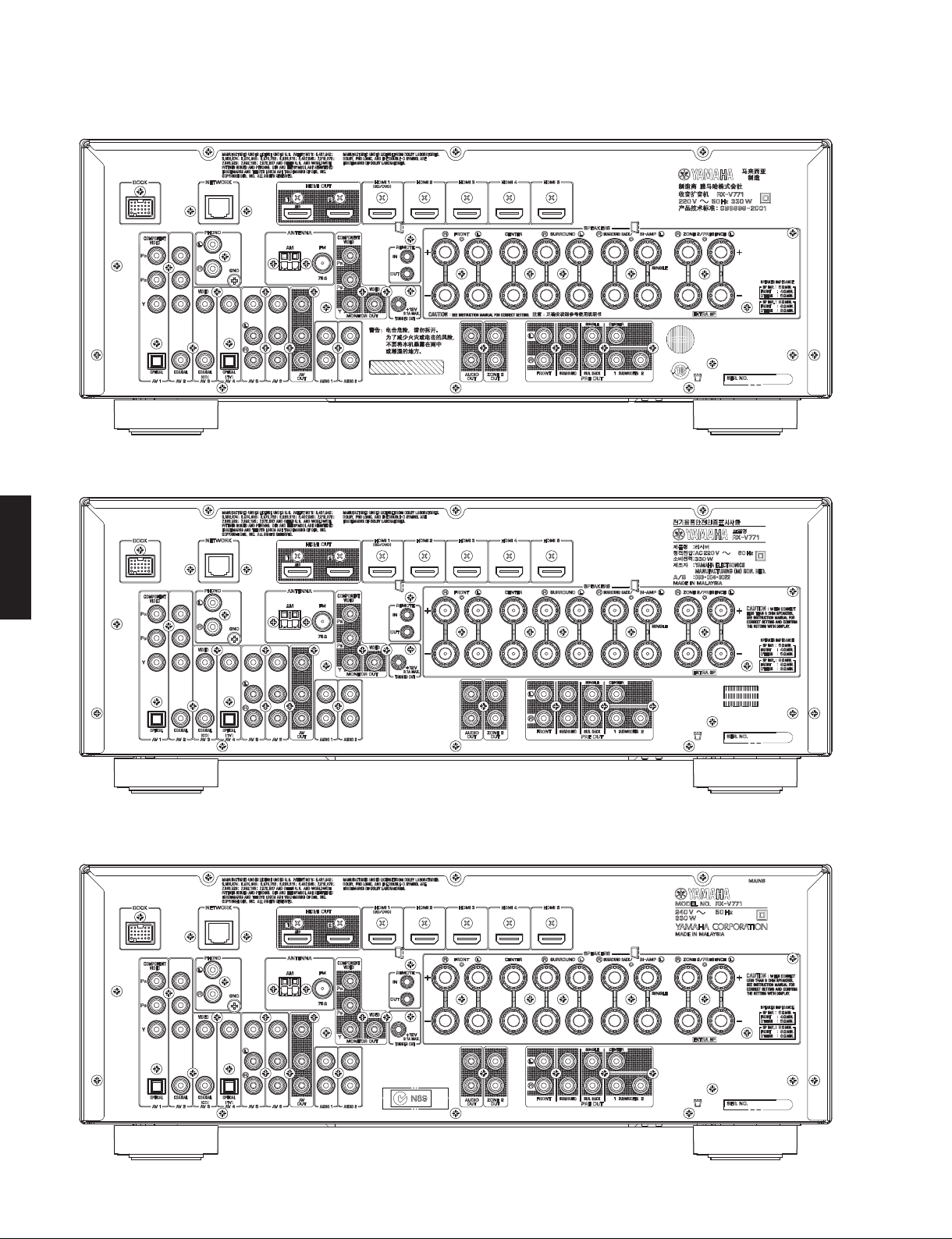
■ REAR PANELS
R model
RX-V771
3
RX-V771
T model
K model
RX-V771
A model
4
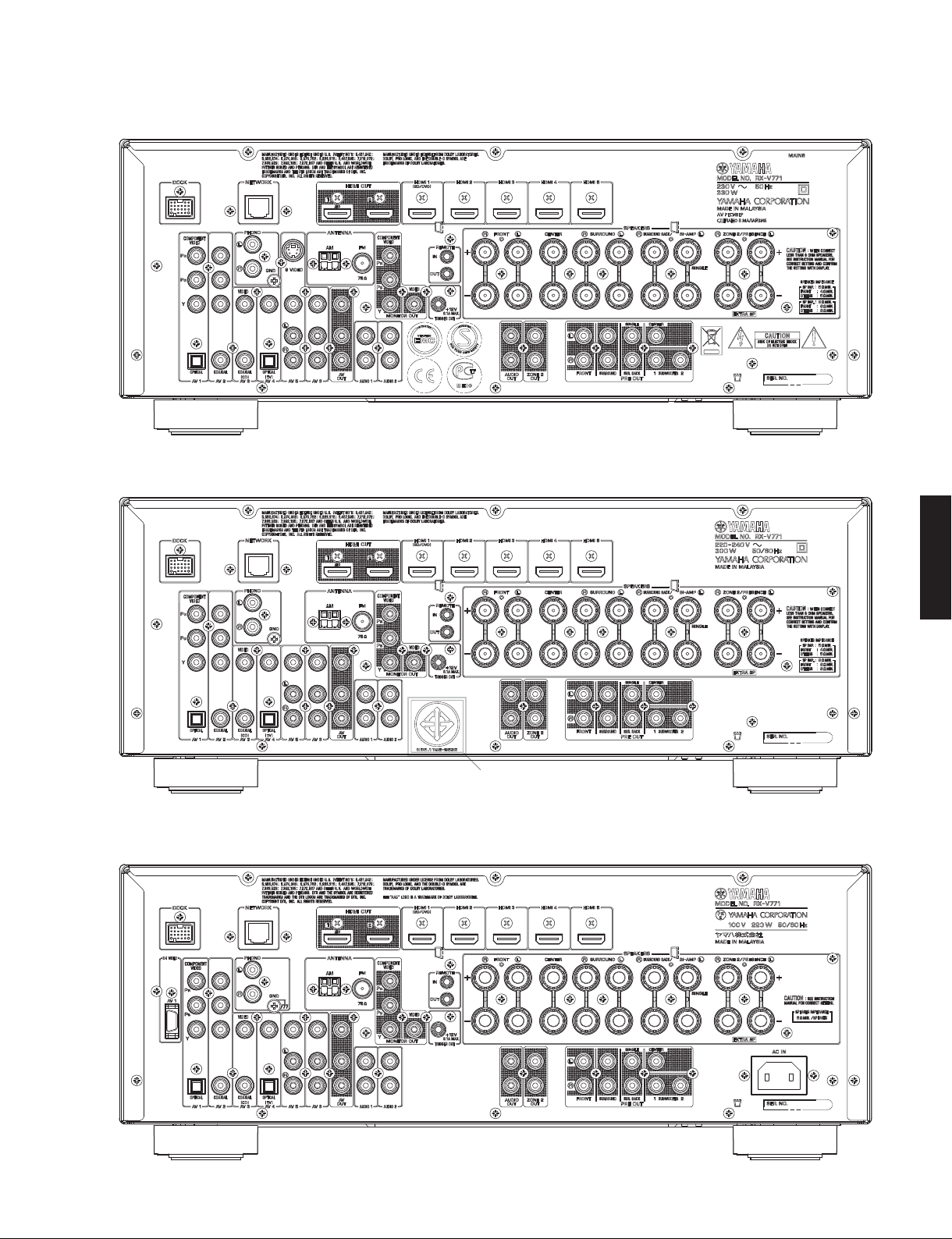
B, G, F models
L, H models
RX-V771
J model
RX-V771
H model
5
RX-V771
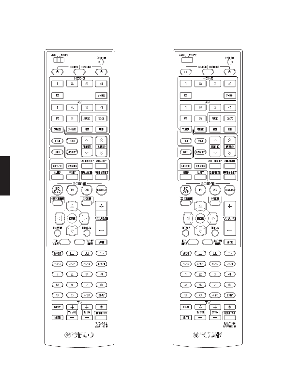
■ REMOTE CONTROL PANELS
RAV442
(R, A, L, H, J models)
RAV443
(T, K, B, G, F models)
RX-V771
6

RX-V771
■ SPECIFICATIONS /
■ Audio Section /
Rated Output Power (Power Amp. Section) /
定格出力(パワーアンプ部)
(1 kHz, 0.9 % THD)
– 1 channel driven –
R, T, K, A, B, G, F, L, H models (8 ohms)
FRONT L/R ................................................................ 130 W/ch
CENTER .......................................................................... 130 W
SURROUND L/R ........................................................ 130 W/ch
SURROUND BACK L/R .............................................130 W/ch
B, G, F models (4 ohms)
FRONT L/R ................................................................ 160 W/ch
J model (6 ohms)
FRONT L/R ................................................................ 130 W/ch
CENTER .......................................................................... 130 W
SURROUND L/R ........................................................ 130 W/ch
SURROUND BACK L/R .............................................130 W/ch
– 2 channel driven simultaneously –
R, T, K, A, B, G, F, L, H models (8 ohms)
FRONT L/R .......................................................110 W + 110 W
CENTER .......................................................................... 110 W
SURROUND L/R ...............................................110 W + 110 W
SURROUND BACK L/R ....................................110 W + 110 W
J model (6 ohms)
FRONT L/R .......................................................110 W + 110 W
(20 Hz to 20 kHz, 0.09 % THD)
– 2 channel driven simultaneously –
R, T, K, A, B, G, F, L, H models (8 ohms)
FRONT L/R ...........................................................95 W + 95 W
J model (6 ohms)
FRONT L/R ...........................................................95 W + 95 W
Maximum Effective Output Power /
(1 channel driven / 1 kHz, 10 % THD) [R, T, L, H, J models]
R, T, L, H models (8 ohms)
FRONT L/R ...................................................................... 160 W/ch
CENTER ............................................................................... 160 W
SURROUND L/R .............................................................. 160 W/ch
SURROUND BACK L/R ................................................... 160 W/ch
J model (6 ohms)
FRONT L/R ...................................................................... 160 W/ch
CENTER ............................................................................... 160 W
SURROUND L/R .............................................................. 160 W/ch
SURROUND BACK L/R ................................................... 160 W/ch
Dynamic Power Per Channel /
FRONT L/R (1 channel driven)
R, T, K, A, B, G, F, L, H models
(8 / 6 / 4 / 2 ohms) .................................. 140 / 180 / 210 / 250 W
J model
(6 / 4 / 2 ohms) ................................................ 150 / 180 / 220 W
Damping Factor /
FRONT L/R to SPEAKER-A ............................................100 or more
Input Sensitivity/Input Impedance /
(1 kHz, 100 W/8 ohms)
PHONO (MM) .................................................... 3.5 mV / 47 k-ohms
AV5 etc. ............................................................ 200 mV / 47 k-ohms
Maximum Input Signal /
PHONO (MM) (0.1 % THD) ..................................................... 60 mV
AV5 etc. (Effect ON) (0.5 % THD) ......................................... 230 mV
オーディオ部
ダイナミックパワー
ダンピングファクタ
最大許容入力
参考仕様
実用最大出力
(20 Hz to 20 kHz, 8 ohms)
入力感度/入力インピーダンス
(1 kHz)
(JEITA)
(IHF)
Output Level/Output Impedance /
REC OUT ......................................................... 200 mV / 1.2 k-ohms
SUBWOOFER (2 channel stereo and FRONT SP: small)
.............................................................................. 1 V / 1.2 k-ohms
R, T, K, A, B, G, F, L, H models
ZONE2 OUT .................................................. 200 mV / 1.2 k-ohms
Headphone Jack Rated Output/Output Impedance /
ヘッドホン出力/出力インピーダンス
AV5 etc. input (1 kHz, 50 mV, 8 ohms) .............. 100 mV / 560 ohms
Frequency Response /
AV5 etc., FRONT (10 Hz to 100 kHz) ...................................0 / -3 dB
RIAA Equalization Deviation /
PHONO (MM) ................................................................... 0 ±0.5 dB
Total Harmonic Distortion /
PHONO (MM) to REC OUT (1 V) ................................0.02 % or less
AV5 etc. (PURE DIRECT) to FRONT SP OUT (50 W)
R, T, K, A, B, G, F, L, H models (8 ohms) .................0.06 % or less
J model (6 ohms) .....................................................0.06 % or less
Signal to Noise Ratio /
PHONO (MM) to REC OUT
R, T, K, A, B, G, F, L, H models (Input shorted 5 mV)
............................................................................. 81 dB or more
J model (Input shorted 2.5 mV)
.................................................................................80 % or less
AV5, etc. (PURE DIRECT) to SP OUT (Input shorted 250 mV)
.............................................................................. 100 dB or more
Residual Noise /
FRONT L/R to SP OUT ................................................150 μV or less
Channel Separation /
PHONO (Input shorted)
...................................................... 60 dB or more / 55 dB or more
AV5, etc. (Input 5.1 k-ohms shorted)
...................................................... 60 dB or more / 45 dB or more
Volume Control /
......................................... MUTE / -80 dB to +16.5 dB / 0.5 dB step
Tone Control Characteristics /
Bass
Boost/Cut ........................................ ±6 dB / 0.5 dB step, at 50 Hz
Turnover frequency .............................................................350 Hz
Treble
Boost/Cut .......................................±6 dB / 0.5 dB step, at 20 kHz
Turnover frequency ............................................................ 3.5 kHz
Filter Characteristics /
FRONT, CENTER, SURROUND, SURROUND BACK small (H.P.F.)
....................fc=40/60/80/90/100/110/120/160/200 Hz, 12 dB/oct.
SUBWOOFER small (L.P.F.)
....................fc=40/60/80/90/100/110/120/160/200 Hz, 24 dB/oct.
Optical Jack, Coaxial Jack Support Fs /
Optical 端子、Coaxial 端子対応 Fs
............................................................................... 32 kHz to 96 kHz
再生周波数帯域
信号対雑音比
残留ノイズ
チャンネルセパレーション
可変範囲/ステップ
フィルタ特性
出力電圧/出力インピーダンス
RIAA 偏差
全高調波歪率
(IHF-A Network)
トーンコントロール特性
(20 Hz to 20 kHz)
(IHF-A network)
(1 kHz / 10 kHz)
RX-V771
7

RX-V771
RX-V771
■ Video Section /
Video Signal Type /
Monitor out (Wall paper) /
R, J models ...........................................................................NTSC
T, K, A, B, G, F, L, H models .....................................................PAL
Video conversion /
.......................................................................................NTSC/PAL
Composite Video Signal Level /
............................................................................... 1 Vp-p / 75 ohms
S-Video Signal Level [B, G, F models]
Y .............................................................................1 Vp-p / 75 ohms
C .....................................................................0.286 Vp-p / 75 ohms
Component Video Signal Level /
Y .............................................................................1 Vp-p / 75 ohms
Pb/Pr ...................................................................0.7 Vp-p / 75 ohms
D4 Video Signal /
Y .............................................................................1 Vp-p / 75 ohms
Pb/Pr ...................................................................0.7 Vp-p / 75 ohms
Video Maximum Input Level /
(VIDEO Conversion Off
............................................................................... 1.5 Vp-p or more
Video Signal to Noise Ratio /
................................................................................... 50 dB or more
Monitor Out Frequency Response /
(VIDEO Conversion Off
Component video signal level /
....................................................................5 Hz to 60 MHz, -3 dB
D4 video signal /
.....................................................................5 Hz to 60 MHz, -3 dB
■ FM Section /
Tuning Range /
R, L, H models .................87.5 to 108.0 MHz / 87.50 to 108.00 MHz
T, K, A, B, G, F models ....................................87.50 to 108.00 MHz
J model ..................................................................76.0 to 90.0 MHz
50 dB Quieting Sensitivity /
(1 kHz, 100 % MOD.)
Mono ......................................................................... 3 μV (20.8 dBf)
Signal to Noise Ratio /
Mono ........................................................................................72 dB
Stereo ......................................................................................70 dB
Harmonic Distortion / 歪率 (1 kHz)
Mono ........................................................................................ 0.3 %
Stereo ...................................................................................... 0.5 %
Antenna Input /
....................................................................... 75 ohms unbalanced
■ AM Section /
Tuning Range /
R, L, H models .........................530 to 1,710 kHz / 531 to 1,611 kHz
T, K, A, B, G, F, J models ....................................... 531 to 1,611 kHz
Antenna /
..................................................................................... Loop antenna
FM部
受信周波数範囲
アンテナ入力
AM部
受信周波数範囲
アンテナ
ビデオ部
ビデオ信号方式
モニターアウト(壁紙)
ビデオコンバージョン
コンポジットビデオ信号
コンポーネントビデオ信号
D4 ビデオ信号
)
)
D4 ビデオ信号
信号対雑音比
[J model]
ビデオ最大許容入力
ビデオ信号対雑音比
コンポーネントビデオ信号
[J model]
50dBSN 感度
モニター出力周波数帯域
(IHF)
(IHF)
■ General /
Power Supply /
R model .......................................AC 110–120/220–240 V, 50/60 Hz
T model ................................................................... AC 220 V, 50 Hz
K model .................................................................. AC 220 V, 60 Hz
A model .................................................................. AC 240 V, 50 Hz
B, G, F models ........................................................ AC 230 V, 50 Hz
L, H models ............................................... AC 220–240 V, 50/60 Hz
J model .............................................................. AC 100 V, 50/60 Hz
Power Consumption /
R, L, H models ........................................................................ 300 W
T, K, A, B, G, F models ........................................................... 330 W
J model ................................................................................... 220 W
Standby Power Consumption (reference data) /
待機時消費電力(参考値)
HDMI control: OFF / Standby through: OFF
...................................................................................0.1 W or less
HDMI control: ON / Standby through: ON
INPUT: HDMI1(HDMI no signal)
Network standby: ON
................................................................................ 2.0 W (typical)
Maximum Power Consumption
R, L, H models ......................................................................... 590 W
Dimensions (W x H x D) /
...................... 435 x 171 x 367.5 mm (17-1/8" x 6-12/16" x 14-8/16")
Weight / 質量
........................................................................... 11.22 kg (24.7 lbs.)
Finish /
T, J models .........................................................................Gold color
R, T, K, A, B, G, F, L, J models ........................................ Black color
R, K, B, G, F, L, H models ............................................ Titanium color
Accessories /
Remote control ..............................................................................x 1
Batteries (R03, AAA, UM-4) ..........................................................x 2
FM antenna (1.4 m) ......................................................................x 1
AM antenna (1.0 m) ......................................................................x 1
YPAO microphone (6.0 m) ............................................................x 1
VIDEO AUX input cover ................................................................x 1
Power cable (2 m) (J model) ........................................................x 1
* Specifications are subject to change without notice.
※ 参考仕様および外観は、製品の改良のため予告なく変更すること
があります。
R .....................General model
T..................... Chinese model
K ...................... Korean model
A .................Australian model
B .......................British model
総合
電源電圧
............................................................................. 2.0 W (typical)
仕上げ
付属品
消費電力
寸法(幅 × 高さ × 奥行き)
G ..................European model
F..................... Russian model
L..................Singapore model
H ...........................Thai model
J .................. Japanese model
8
RX-V771
Manufactured under license from Dolby Laboratories. Dolby, Pro Logic and
the double-D symbol are trademarks of Dolby Laboratories.
ドルビーラボラトリーズからの実施権に基づき製造されています。「ドルビー」、
「PROLOGIC」、「SurroundEX」およびダブル D 記号
ズの商標です。
DTS and the Symbol are registered trademarks, & DTS-HD, DTS-HD Master
Audio, and the DTS logos are trademarks of DTS, Inc.
Prod uct includes software. © DTS, Inc. All Rights Reserved.
DTSおよび記号は DTS 社の登録商標です。また、DTS-HD、DTS-HDMaster
Audio、および DTS ロゴは DTS 社の商標です。製品にはソフトウェアを含みます。
著作権 DTS 社。不許複製。
“iPod” is a trademark of Apple Inc., registered in the U.S. and other countries.
“iPhone” is a trademark of Apple Inc.
iPod は、米国および他の国々で登録された AppleInc. の商標または登録商標で
す。iPhone は、AppleInc. の商標または登録商標です。
MPEG Layer-3 audio coding technology licensed from Fraunhofer IIS and
Thomson.
MPEGLayer3 音声圧縮技術は FraunhoferIIS および Thomson によってライセン
ス供与されています。
、ドルビーラボラトリー
AAC ロゴマーク はドルビーラボラトリーズの商標です。
Windows XP, Windows Vista, Windows 7, Windows Media Audio, Windows
Media Connect and Windows Media Player are either registered
trademarks or trademarks of Microsoft corporation in the United States
and/or other countries.
WindowsXP、WindowsVista、Windows7、WindowsMediaAudio、
WindowsMediaConnect、WindowsMediaplayer は、米国 Microsoft
Corporation の米国およびその他の国における登録商標、または商標です。
• DIMENSIONS /
Top view
72
(2-7/8")
寸法図
ø 60
22
RX-V771
(7/8")
This receiver supports network connections.
本機はネットワーク接続に対応しています。
Bluetooth is a registered trademark of the Bluetooth SIG and is used by
Yamaha in accordance with a license agreement.
Bluetooth は、BluetoothSIG の登録商標でありヤマハはライセンスに基づき使
用しています。
“HDMI,” the “HDMI” logo and “High-Definition Multimedia Interface” are
trademarks, or registered trademarks of HDMI Licensing LLC.
HDMI、HDMI ロゴ、および High-DefinitionMultimediaInterface は、HDMI
Licensing,LLC の商標または登録商標です。
“x.v.Color” is a trademark of Sony Corporation.
「x.v.Color」は、ソニー株式会社の商標です。
“SILENT CINEMA” is a trademark of Yamaha Corporation.
「サイレントシネマ™ SILENTCINEMA ™」はヤマハ株式会社の登録商標です。
193 (7-5/8")
50
59
(2")
(2-1/4")
Front view
335 (13-1/4")
435 (17-1/8")
367 (14-1/2")
324 (12-3/4")
21
(7/8")
150 (5-7/8")
171 (6-3/4")
21
(7/8")
Unit: mm (inch)
単位:mm(インチ)
9
RX-V771
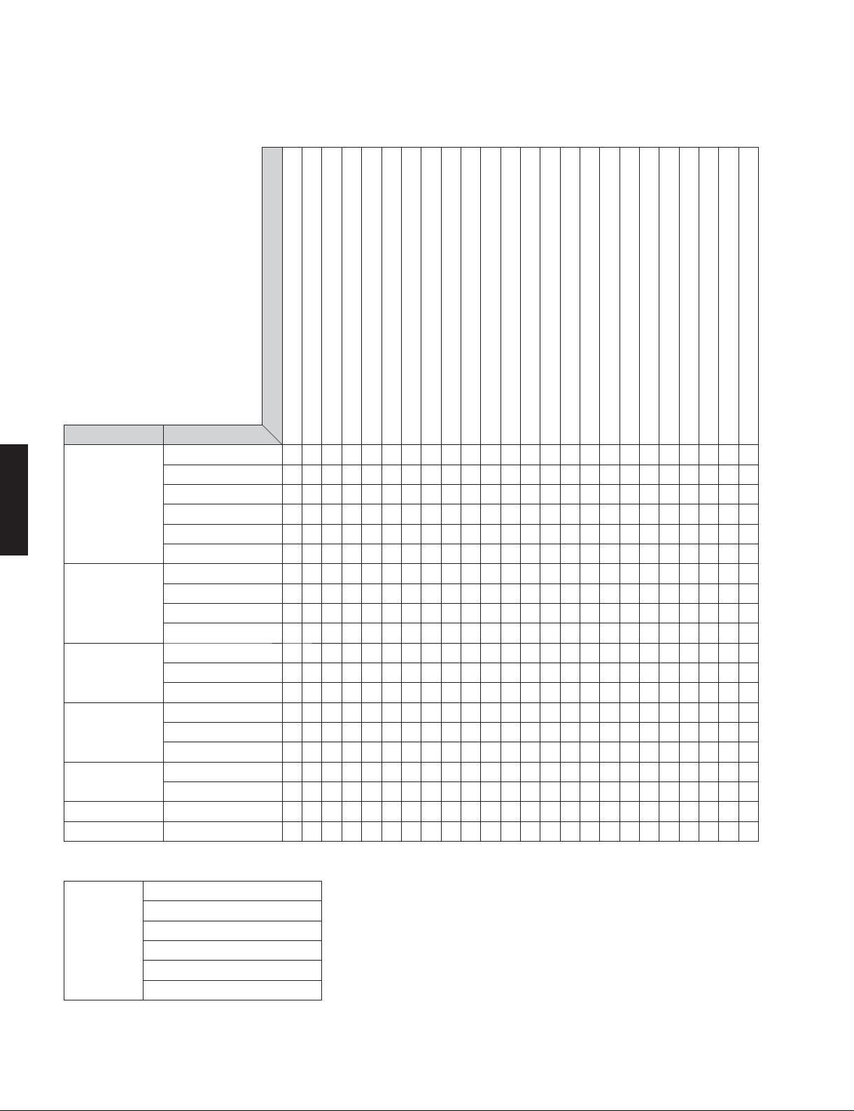
• SELECT MENU
Sound field parameters
Parameter
RX-V771
Category Program
MOVIE THEATER Standard
Spectacle
Sci-Fi
Adventure
Drama
Mono Movie
ENTERTAINMENT Sports
Action Game
Roleplaying Game
Music Video
CLASSICAL Hall in Munich
Hall in Vienna
Chamber
LIVE/CLUB Cellar Club
The Roxy Theatre
The Bottom Line
STEREO 2ch Stereo
7ch Stereo
SUR. DECODE
STRAIGHT
Decode Type (*1)
DSP Level: -6 to +3 dB, [0]
Initial Delay: 1 to 99 ms
Room Size: 0.1 to 2.0
Liveness: 0 to 10
Surround Initial Delay: 1 to 49 ms
Surround Room Size: 0.1 to 2.0
Surround Liveness: 0 to 10
Center Level: 0 to 100 %, [100 %]
Surround L Level: 0 to 100 %, [100 %]
Surround R Level: 0 to 100 %, [100 %]
Surround Back Level: 0 to 100 %, [100 %]
Surround Back Initial Delay: 1 to 49 ms
Surround Back Room Size: 0.1 to 2.0
Surround Back Liveness: 0 to 10
Surround Back L Level: 0 to 100 %, [7.1CH: 35 %, 6.1CH: 50 %]
Surround Back R Level: 0 to 100 %, [7.1CH: 35 %, 6.1CH: 50 %]
Front Presence L Level: 0 to 100 % [100 %]
Front Presence R Level: 0 to 100 % [100 %]
Reverb Time: 1.0 to 5.0 s
Reverb Delay: 0 to 250 ms
Reverb Level: 0 to 100 %
Direct: Auto / Off, [Auto]
●● ●●● ●●● ●
●●●● ●● ●● ●
●●●● ●● ●● ●
●●●● ●● ●● ●
●●●● ●● ●● ●
●●●● ●●● ●
●●● ●● ●● ●
●●● ●● ●● ●
●●● ●● ●● ●
●●● ●● ●● ●
●●●● ●
●●●● ●
●● ● ●●● ●
●●●● ●
●●●● ●●● ●
●●●● ●
●●
●●●● ●●●● ●
● ●
Reset
*1 Surround Decoder
Decode Type
10
Dolby Pro Logic
Dolby PL IIx Movie / Dolby PL II Movie
Dolby PL IIx Music / Dolby PL II Music
Dolby PL IIx Game / Dolby PL II Game
Neo:6 Cinema
Neo:6 Music
RX-V771
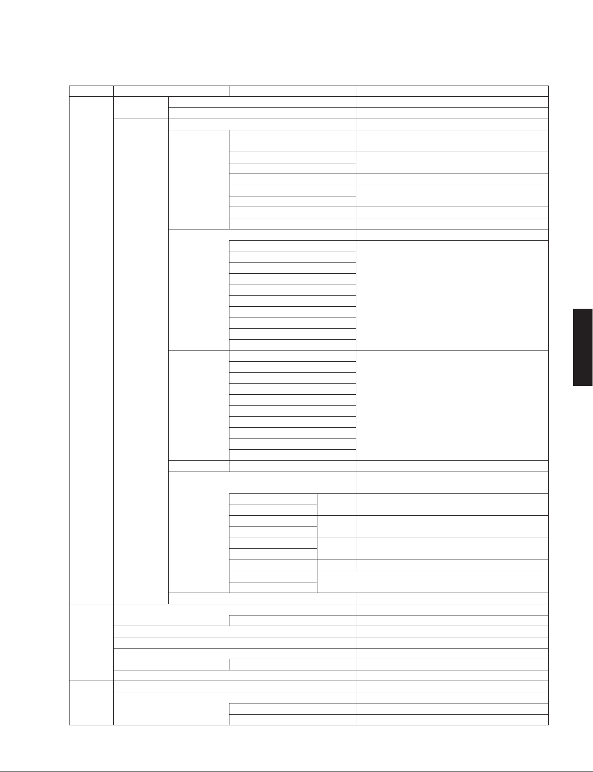
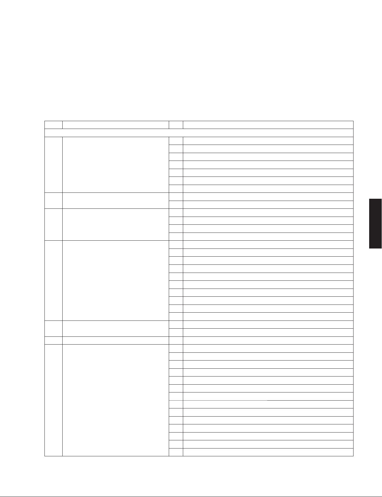
• SET MENU TABLE /
MAIN MENU SUB-MENU PARAMETER VALUE [INITIAL VALUE]
Speaker Auto Measure Optimizes the speaker configuration automatically using YPAO.
SetupResult Not Available
Manual Power Amp Assign [Basic] / 7ch +1ZONE / 5ch BI-AMP
Sound Setup Lipsync [Auto] / Manual
Dynamic Range [Maximum] / Standard / Minimum/Auto
Max. Volume -30.0 to +16.5 dB (Maximum volume), [+16.5 dB], 5.0 dB step
Initial Volume [Off] / On
Adaptive DSP Level Off / [On]
Video Setup Analog to Analog Conversion Off / [On]
Processing [Off] / On
セットメニュー
Configuration Front Large / [Small]
* When “Subwoofer” is set to “None”, “Front” is disabled.
Center
Surround
Surround Back Large x1 / Large x2 / Small x1 / [Small x2] / None
Front Presence
Subwoofer
Extra Bass [Off] / On
Bass Cross Over 40 / 60 / [80] / 90 / 100 / 110 / 120 / 160 / 200 Hz
Distance Meter / Feet
Front L
Front R
Center
Surround L
Surround R 0.30 to 24.00 m, [3.00 m], 0.05 m step
Surround Back L 1.0 to 80.0 ft, [10.0 ft], 0.2 ft step
Surround Back R
Front Presence L
Front Presence R
Subwoofer
Level Front L
Front R
Center
Surround L
Surround R -10.0 to +10.0 dB, [0.0 dB], 0.5 dB step
Surround Back L
Surround Back R
Front Presence L
Front Presence R
Subwoofer
Parametric EQ PEQ Select Manual / YPAO : Flat / YPAO : Front / YPAO : Natural / [Through]
PEQ Data Copy Flat > Manual / Front > Manual / Natural > Manual
Front L Band / Gain▶ Band: #1 to #7
Front R
Center Freq. / Gain▶ Frequency: 31.3 Hz to 16.0 kHz, [62.5 Hz]
Surround L
Surround R Q / Gain
Surround Back L
Surround Back R Clear OK / CANCEL * Select “ENTER”
Front Presence L
Front Presence R * When “PEQ Select” is set to “Manual”, this section is disabled.
Test Tone [Off] / On
Select “Manual” 0 to 250 ms, [0 ms], 1 ms step
Select “On” Mute, -80 to +16.5 dB, [0.0 dB], 0.5 dB step
Resolution Through / [Auto] / 576p / 720p / 1080i / 1080p * Select “ENTER”
Aspect [Through] / 16:9 Normal
Large / [Small] / None
[Use] / None
* Select “ENTER”
Gain: -20.0 to +6.0 dB, [0.0 dB], 0.5 dB step
▲
Gain: -20.0 to +6.0 dB, [0.0 dB], 0.5 dB step
▲
Q: 0.500 to 10.080, [1.000]
▶
Gain: -20.0 to +6.0 dB, [0.0 dB], 0.5 dB step
▲
RX-V771
11
RX-V771
RX-V771
12
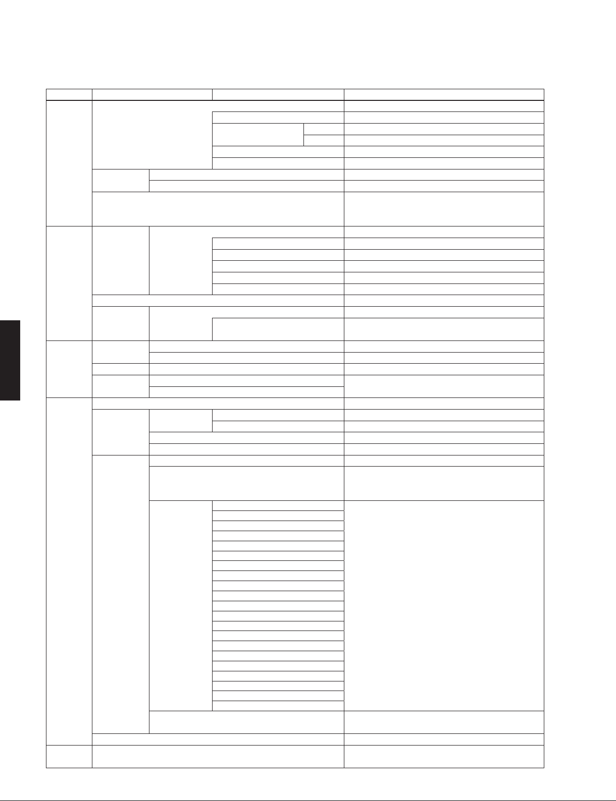
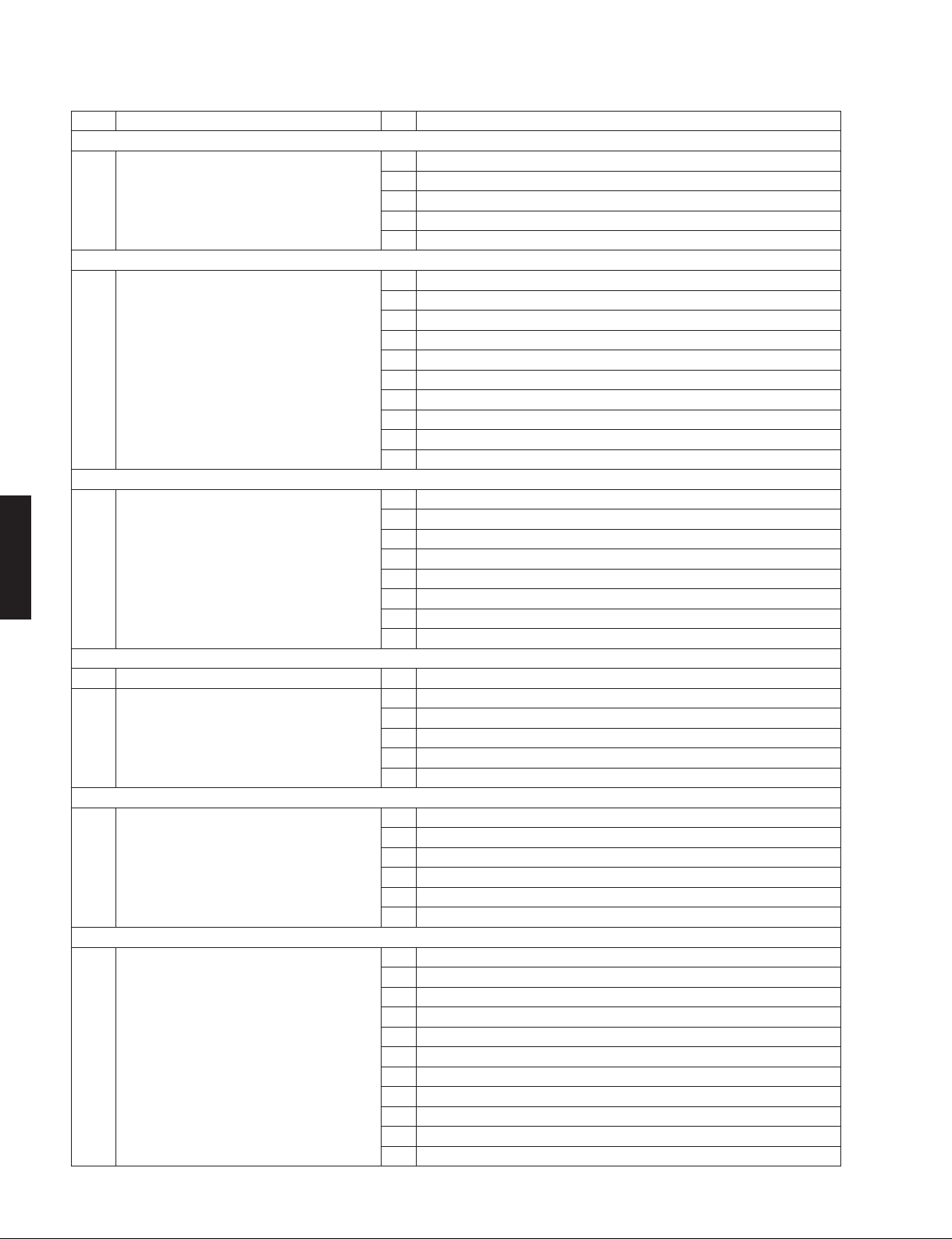
MAIN MENU SUB-MENU PARAMETER VALUE [INITIAL VALUE]
HDMI Setup HDMI Control [Off] / On
Control Select [OUT1 (TV1)] / OUT2 (TV2)
TV Audio Input TV1 AV1 / AV2 / AV3 / [AV4] / AV5 / AV6 / AUDIO1 / AUDIO2
TV2 [AV1] / AV2 / AV3 / AV4 / AV5 / AV6 / AUDIO1 / AUDIO2
ARC (Audio Return Channel) Off / [On]
Standby Sync Off / On / [Auto]
Audio Output Amp Off / [On]
HDMI OUT1 (TV1), HDMI OUT2 (TV2), [Off] / On
Standby Through [Off] / On
* When HDMI Control is set to “On”, “Standby Through” is
disabled.
Network IP Address DHCP [Off] / On
Setup IP Address xxx.xxx.xxx. x
Subnet Mask xxx.xxx.xxx. x
Default Gateway xxx.xxx.xxx. x
DNS Server (P) Primary x. x. x. x
DNS Server (P) Secondary x. x. x. x
Network Standby [Off] / On
MAC Address Mode [Off] / On
Filter Address Setup MAC Address 1 to 10
xx : xx : xx : xx : xx : xx
Multi Zone Zone2 Set Max. Volume -30.0 to +16.5 dB (Maximum volume), [+16.5 dB], 5.0dB step
Setup Initial Volume [Off] / On
Party Mode Set Zone2 Disable / [Enable]
Zone Rename Main Input is possible to 9 characters
Zone2
Function Auto Power Down Off / 4 Hours / [8 Hours] / 12 Hours
Setup Display Set Front Panel Display Dimmer -4 to 0, [0]
Scroll [Continue] / Once
Short Message [On] / Off
Wall Paper Picture1 / Picture2 / Picture3 / Gray
Trigger Outpu
Memory Guard [Off] / On
Language
Setup
t Trigger Mode [Power] / Source / Manual
Target Zone Main / Zone2 / [All]
* When “Trigger Mode” is set to “Power”, “Target Zone” is
disabled.
Target Source HDMI1
Manual Low / [High]
HDMI2
HDMI3
HDMI4
HDMI5
AV1
AV2
AV3
AV4
AV5 Low / [High]
AV6
V-A UX
AUDIO1
AUDIO2
PHONO
TUNER
Napster
PC
NET RADIO
USB
DOCK
* When “Trigger Mode” is set to “Source”, “Target Source” is
disabled.
* When “Trigger Mode” is set to “Manual”, “Manual” is disabled.
English (English),
Deutsch (German), Español (Spanish), РУccкий (Russian)
日本語
(Japanese), Français (French),
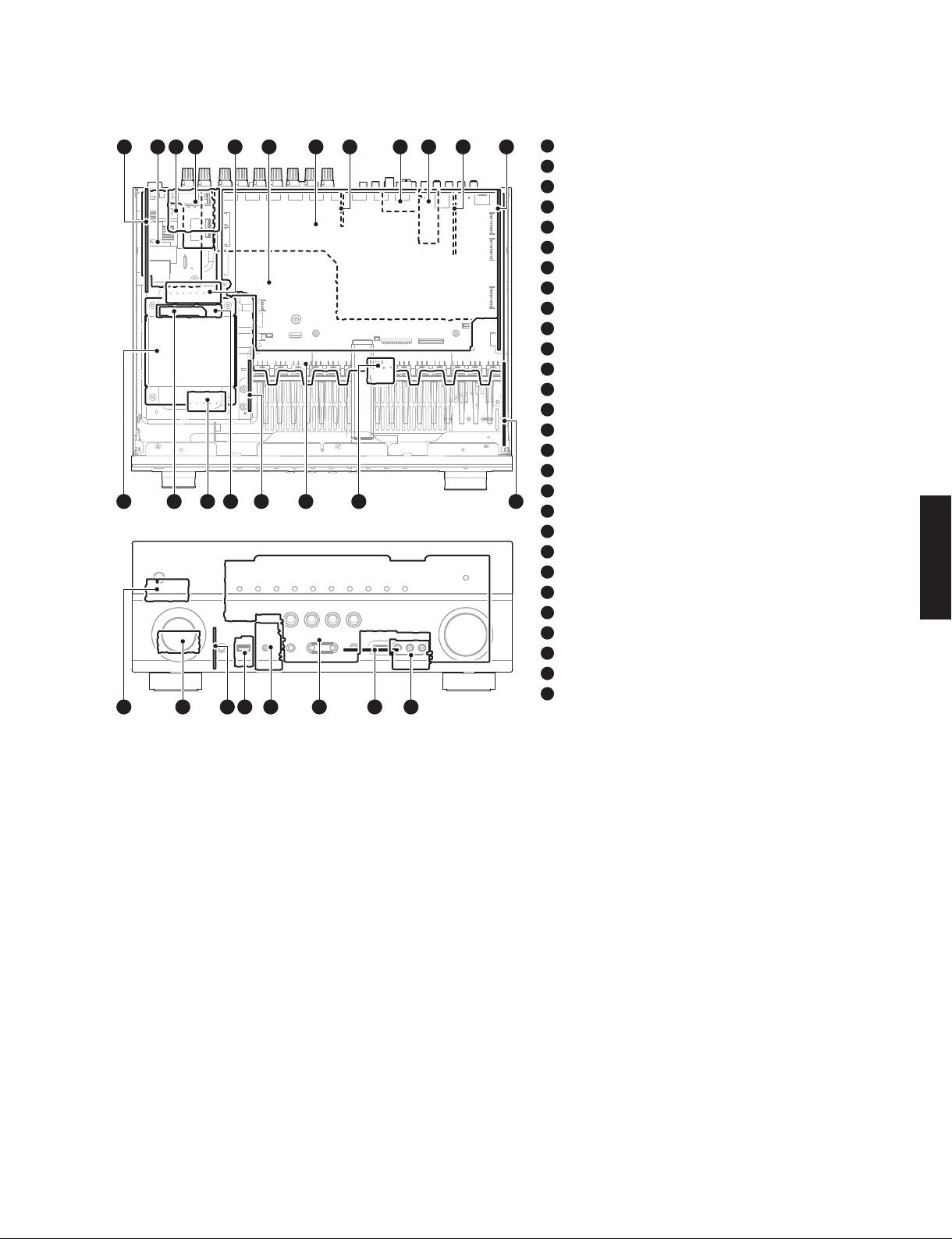
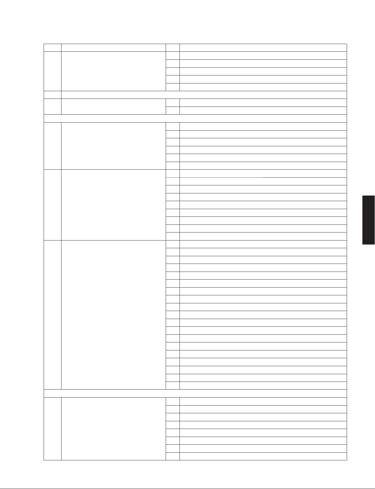
■ INTERNAL VIEW
Top view
18
19
5243679
1617
1518
10
11 1 2
Front view
21 23
22 262524 27 28
1
VIDEO (2) P.C.B.
2
VIDEO (3) P.C.B.
3
VIDEO (8) P.C.B. (R model)
4
OPERATION (8) P.C.B.
5
MAIN (2) P.C.B.
6
DIGITAL (1) P.C.B.
7
VIDEO (1) P.C.B.
8
VIDEO (4) P.C.B.
9
AM/FM TUNER
10
VIDEO (5) P.C.B. (B, G, F models)
11
VIDEO (10) P.C.B.
12
OPERATION (2) P.C.B.
13
OPERATION (7) P.C.B.
14
OPERATION (10) P.C.B.
15
MAIN (1) P.C.B.
16
MAIN (6) P.C.B.
17
VIDEO (9) P.C.B. (R model)
18
131420
VIDEO (7) P.C.B.
19
VIDEO (6) P.C.B. (T, K, A, B, G, F, L, H, J models)
20
POWER TRANSFORMER
21
OPERATION (5) P.C.B.
22
OPERATION (6) P.C.B.
23
OPERATION (3) P.C.B.
24
OPERATION (11) P.C.B.
25
OPERATION (4) P.C.B.
26
OPERATION (1) P.C.B.
27
DIGITAL (2) P.C.B.
28
OPERATION (12) P.C.B.
RX-V771
RX-V771
■ SERVICE PRECAUTIONS /
サービス時の注意事項
Safety measures
• Some internal parts in this product contain high voltages
and are dangerous.
Be sure to take safety measures during servicing, such
as wearing insulating gloves.
• Note that the capacitors indicated below are dangerous
even after the power is turned off because an electric
charge remains and a high voltage continues to exist
there.
Before starting any repair work, connect a discharging
resistor (5 k-ohms/10 W) to the terminals of each
capacitor indicated below to discharge electricity.
The time required for discharging is about 30 seconds
per each.
C1076, C1082–1086 on MAIN (1) P.C.B.
C3706 on VIDEO (2) P.C.B.
For details, refer to “PRINTED CIRCUIT BOARDS”.
安全対策
・ この製品の内部には高電圧部分があり危険です。修理
の際は、絶縁性の手袋を使用するなどの安全対策を
行ってください。
・ 下記のコンデンサには電源を OFF にした後も電荷が残
り、高電圧が維持されており危険です。
修理作業前に放電用抵抗(5k Ω /10W)を下記の各コ
ンデンサの端子間に接続して放電してください。
放電所用時間は各々約 30 秒間です。
MAIN(1)P.C.B. の C1076、C1082 〜 1086
VIDEO(2)P.C.B. の C3706
詳しくは “PRINTEDCIRCUITBOARDS” を参照してくだ
さい。
13

RX-V771
RX-V771
■ DISASSEMBLY PROCEDURES /
(Remove parts in the order as numbered.)
Disconnect the power cable from the AC outlet.
1. Removal of Top Cover
a. Remove 4 screws (①), screw (②) and 5 screws (③).
(Fig. 1)
b. Slide the top cover rearward to remove it. (Fig. 1)
2. Removal of Front Panel Unit and Sub-Chassis Unit
a. Remove knob (VOLUME) and knob (INPUT). (Fig. 1)
b. Remove 6 screws (④) and then remove the front
panel unit. (Fig. 1)
c. Remove 2 push rivets and then remove the side plate
(L) and side plate (R). (Fig. 1)
d. Remove CB10, CB458, CB471, CB902 and CB951.
(Fig. 1)
e. Remove 2 screws (⑤) and then remove the sub-
chassis unit. (Fig. 1)
Top cover
トップ カバ ー
分解手順
(番号順に部品を外してください。)
AC 電源コンセントから、電源コードを抜いてください。
1.トップカバーの外し方
a. ①のネジ 4 本、②のネジ 1 本、③のネジ 5 本を外し
ます。(Fig.1)
b. トップカバーの後部を持ち上げ、外します。(Fig.1)
2. フロントパネルユニットと
サブシャーシユニットの外し方
a. ノブ(VOLUME)とノブ(INPUT)を外します。(Fig.1)
b. ④のネジ 6本を外し、フロントパネルユニットを前方
に外します。(Fig.1)
c. プッシュリベット 2 個を外し、サイドプレート(L)、
サイドプレート(R)を外します。(Fig.1)
d. CB10、CB458、CB471、CB902、CB951 を外します。
(Fig.1)
e. ⑤のネジ 2 本を外し、サブシャーシユニットを外しま
す。(Fig.1)
②
③
Push rivet
プッシュリベット
Knob (INPUT)
ノブ(INPUT)
Knob (VOLUME)
ノブ(VOLUME)
Side plate (L)
サイドプレート(L)
④
⑤
④
①
OPERATION (3) P.C.B.
CB471
CB951
⑤
Sub-chassis unit
サブシャーシユニット
Front panel unit
フロントパネル ユニット
CB10
①
CB81
CB902
DIGITAL (1) P.C.B.
CB458
OPERATION (2) P.C.B.
Push rivet
プッシュリベット
Side plate (R)
サイドプレート(R)
14
Fig. 1
RX-V771
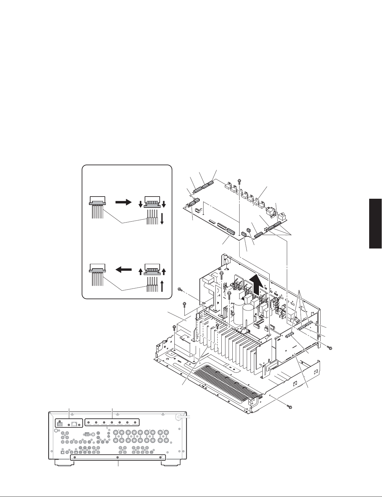
3. Removal of DIGITAL (1) P.C.B.
a. Remove 3 screws (⑥) and 7 screws (⑦). (Fig. 3)
b. Remove 3 screws. (⑧). (Fig. 2)
c. Remove CB21, CB82, CB87 and CB947. (Fig. 2)
d. Unlock and remove CB83, CB85 and CB948. (Fig. 2)
e. Remove the DIGITAL (1) P.C.B. which is connected
directly to the OPERATION (2) P.C.B. with board-toboard connectors. (Fig. 2)
4. Removal of AMP Unit and Power Transformer
a. Remove screw (⑨), 2 screws (⑩), 5 screws (⑪)and
4 screws(⑫). (Fig. 2)
b. Remove 3 screws (⑬). (Fig. 3)
c. Remove the amp unittogether with the power
transformer. (Fig. 2)
Remove CB83, CB85, CB948
CB83、CB85、CB948 の外し方
Connected
接続
Cable / ケーブル
Connect CB83, CB85, CB948
CB83、CB85、CB948 の取り付け方
Connected
接続
Unlock the connector
①
コネ クター ロック解 除
Remove the cable
②
ケーブルを外す
①①
②
Lock the connector
①
コネ クター ロック
Insert the cable
②
ケーブルを差し込む
CB87
CB947
CB948
3. DIGITAL(1)P.C.B. の外し方
a. ⑥のネジ 3 本、⑦のネジ 7 本を外します。(Fig.3)
b. ⑧のネジ 3 本を外します。(Fig.2)
c. CB21、CB82、CB87、CB947 を外します。(Fig.2)
d. ロックを外し、CB83、CB85、CB948 を外します。(Fig.2)
e. DIGITAL(1)P.C.B. を外します。ただし、DIGITAL(1)
P.C.B. は OPERATION(2)P.C.B. に基板対基板コネクター
で直接接続されています。(Fig.2)
4. アンプユニットと電源トランスの外し方
a. ⑨のネジ1本、⑩のネジ 2 本、⑪のネジ 5 本、⑫の
ネジ 4 本を外します。(Fig.2)
b. ⑬のネジ 3 本を外します。(Fig.3)
c. アンプユニットと電源トランスを一緒に取り外しま
す。(Fig.2)
CB23 (B, G, F models)
CB21
CB85
⑧
DIGITAL (1) P.C.B.
CB917
CB918
CB920
Board-to-board connectors
基板対基板コネクター
CB82
CB83
RX-V771
Cable / ケーブル
⑥ ⑦
①①
②
Power transformer
電源トランス
アンプ ユ ニット
⑪
⑫
AMP unit
Rear view
⑪
⑫
Fig. 2
⑩
⑨
Board-to-board connectors
基板対基板コネクター
CB459
CB460
CB461
OPERATION (2) P.C.B.
⑧
⑪
⑬
Fig. 3
15
RX-V771
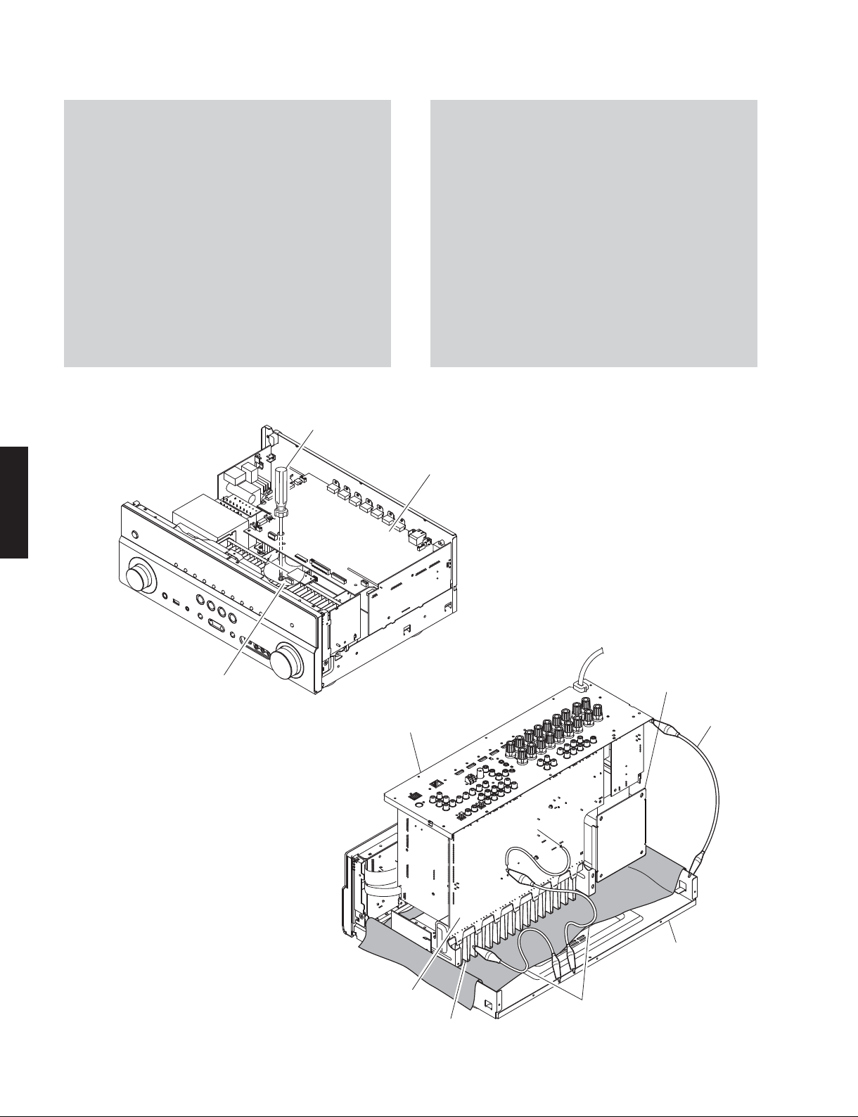
When checking the P.C.B.s:
• Follow the procedure below to place the P.C.B.s (with
rear panel) and power transformer upright. (Fig. 5)
a. Remove the top cover. (Fig. 1)
b. Remove screw (⑨), 2 screws (⑩), 5 screws (⑪)
and 4 screws (⑫). (Fig. 2)
c. Remove 3 screws (⑬). (Fig. 3)
• Connect the heatsink, rear panel and G101 on MAIN
(1) P.C.B. to the chassis with a ground lead or the
like. (Fig. 5)
• Reconnect all cables (connectors) that have been
disconnected.
• When connecting the flexible flat cable, be careful
with polarity.
Screwdriver
プラスドライバー
P.C.B. をチェックする場合には:
・ リアパネルと一緒に P.C.B. と電源トランスを立ち上
げて置きます。(Fig.5)
a. トップカバーを取り外します。(Fig.1)
b. ⑨のネジ1本、⑩のネジ 2 本、⑪のネジ 5 本、
⑫のネジ 4 本を外します。(Fig.2)
c. ⑬のネジ 3 本を外します。(Fig.3)
・ ヒートシンク、リアパネル、MAIN(1)P.C.B. の
G101 のアースをリード線等でシャーシに接続してく
ださい。(Fig.5)
・ 外したケーブル(コネクター)をすべて接続します。
・ フラットケーブルを接続する際、極性に注意してく
ださい。
DIGITAL (1) P.C.B.
RX-V771
MAIN (1) P.C.B.
⑨
Fig. 4
Rear panel
リアパ ネ ル
Power transformer
電源トランス
Ground lead
アース 線
G101
16
MAIN (1) P.C.B.
ヒートシンク
Heatsink
Chassis
シャーシ
Ground lead
アース 線
Fig. 5

RX-V771
■ UPDATING FIRMWARE /
When the following parts are replaced, the firmware must
be updated to the latest version.
DIGITAL P.C.B.
FPGA Flash ROM: IC82 on DIGITAL P.C.B.
NETWORK Flash ROM: IC904 on DIGITAL P.C.B.
DSP(TI) Flash ROM: IC923 on DIGITAL P.C.B.
ファームウェアのアップデート
● Confirmation of firmware version and checksum
Before and after updating the firmware, check the
firmware version and checksum by using the selfdiagnostic function menu.
Start up the self-diagnostic function and select “S4.
ROM VERSION/CHECKSUM” menu.
Using the sub-menu, have the firmware version and
checksum displayed, and note them down.
(See “SELF-DIAGNOSTIC FUNCTION”)
* When the firmware version is different from
written one after updating, perform the updating
procedure again from the beginning.
下記の部品を交換した場合、ファームウェアを最新バー
ジョンにアップデートする必要があります。
DIGITALP.C.B.
FPGA フラッシュ ROM: DIGITALP.C.B. の IC82
NETWORK フラッシュ ROM:DIGITALP.C.B. の IC904
DSP(TI)フラッシュ ROM: DIGITALP.C.B. の IC923
●
ファームウェアのバージョンとチェックサムの確認
ファームウェアのアップデートの前後に、ファーム
ウェアのバージョンとチェックサムをダイアグで確
認します。
ダイアグを起動し、“S4.ROM VERSION/CHECKSUM”
メニューを選択します。
サブメニューでファームウェアのバージョンと
チェックサムを表示し、それらを書きとめます。
(「ダイアグ」参照)
※ アップデート後、ファームウェアのバージョンが
書き込まれたものと異なる場合、アップデートの
操作を最初からやり直してください。
RX-V771
● Initializing the back-up IC (EEPROM: IC83 on DIGITAL (1) P.C.B.)
After updating the firmware, the back-up IC MUST
be initialized by the following procedure to have
proper memorization of the set up information
(soundfield parameters, system memory and tuner
presetting, etc.).
Start up the self-diagnostic function and select “S3.
FACTORY PRESET” menu. (See “SELF-DIAGNOSTIC
FUNCTION”)
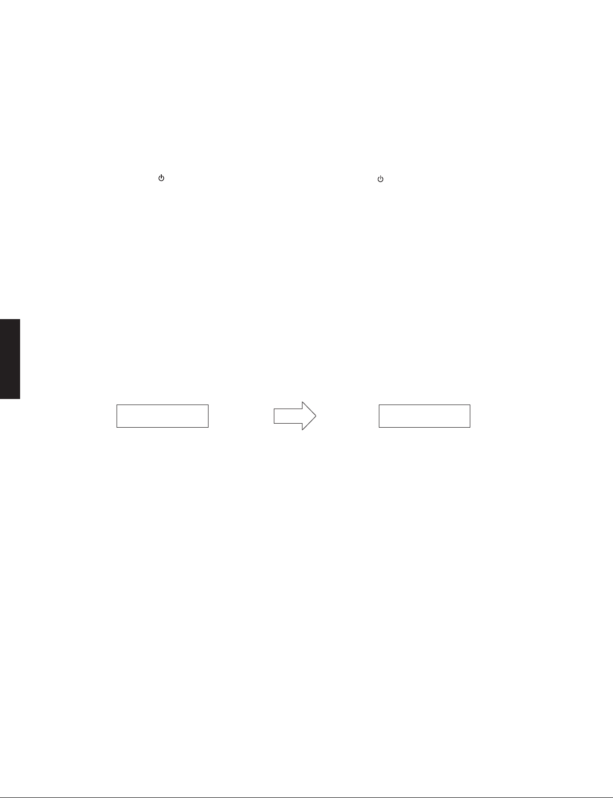
Select “PRESET RSRV”, press the “MAIN ZONE
key to turn off the power once and turn on the power
again. Then the back-up IC is initialized.
● Required Tools
• USB storage device
• Firmware
RX-V771: RXV771-xxxx.bin
● Preparation
1. Download the latest firmware from the specified
download source to the folder of the PC.
2. Copy the latest firmware from the PC to the root
folder of the USB storage device.
Note) When the latest firmware is copied to a sub-
folder of the USB storage device, the update
will not proceed.
● バックアップ IC の初期化
(EEPROM:DIGITAL(1)P.C.B. の IC83)
ファームウェアのアップデート後、設定情報(音
場プログラムのパラメーターやシステムメモリー、
チューナープリセット等)を正常に記憶するために、
下記の方法でバックアップ IC を初期化する必要が
あります。
本機のダイアグを起動し、“S3.FACTORYPRESET” メ
ニューを選択します。
(「ダイアグ」参照)
”
“PRESETRSRV” を選択し、“MAINZONE
して電源を一度きってから、もう一度電源を入れる
とバックアップ IC が初期化されます。
” キーを押
● 必要なツール
・ USB フラッシュメモリー
・ ファームウェア
RX-V771:RXV771-xxxx.bin
● 準備
1. 指定のダウンロード先から、最新のファームウェ
アを PC のフォルダへダウンロードしてください。
2. PC から USB フラッシュメモリーのルートフォル
ダへ最新のファームウェアをコピーします。
注意)最新のファームウェアをサブフォルダにコピー
した場合、書き込みはできません。
17
RX-V771
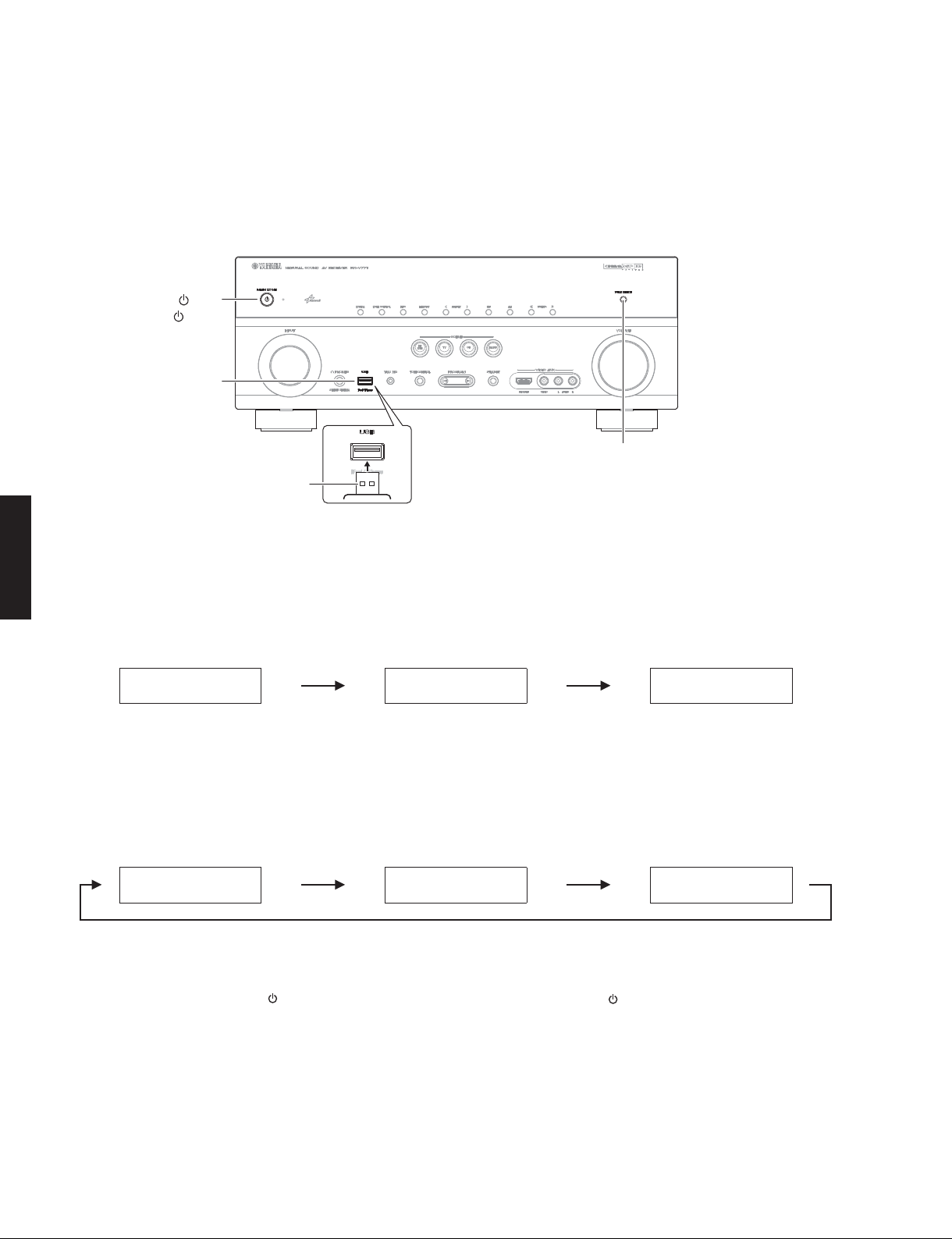
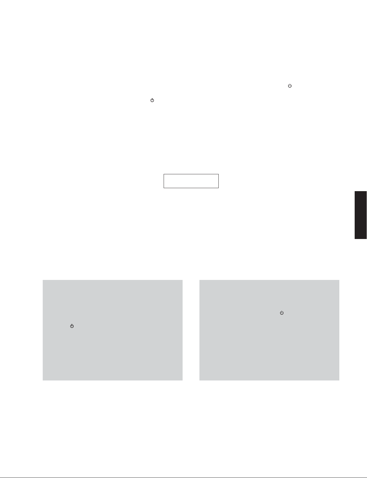
● Operation Procedures
1. Insert the USB storage device to the USB port.
(Fig. 1)
2. While pressing the “PURE DIRECT” key, connect
the power cable to the AC outlet. (Fig. 1)
"MAIN ZONE " key
"MAINZONE" キー
USB port
USB ポート
USB storage device
USB フラッシュメモリー
● 操作手順
1. USB ポートに USB フラッシュメモリーを差し込み
ます。(Fig.1)
2. “PUREDIRECT” キーを押しながら、電源コードを
AC コンセントに接続します。(Fig.1)
"PURE DIRECT" key
"PUREDIRECT" キー
Fig. 1
RX-V771
3. The USB UPDATE mode is activated and “USB
UPDATE” is displayed. Writing of the firmware
starts automatically. (Fig. 2)
Writing is started. /
USBUPDATE
書き込み開始
VERIFYING...
4. When writing of the firmware is completed,
“Update Success”, “Please...” and “Power Off!”
are displayed repeatedly. (Fig. 3)
Writing is completed. /
UpdateSuccess
5. Press the “MAIN ZONE
書き込み完了
Please...
” key to turn off the
power. (Fig. 1)
Fig. 2
Fig. 2
3. USBUPDATE モードが起動し、“USB UPDATE” が
表示されて、ファームウェアの書き込みが自動的
に開始されます。(Fig.2)
Writing being executed. /
書き込み中
Sx-x:xx%
4. ファームウェアの書き込み完了後、“Update
Success”、“Please...”、“PowerOff!” が繰り返し表
示されます。(Fig.3)
PowerOff!
5. “MAINZONE
” キーを押して電源を切ります。
(Fig.1)
18
6. Remove the USB storage device from the USB
port. (Fig. 1)
7. Start up the self-diagnostic function and check
that the firmware version and checksum are
the same as written ones. (See “Confirmation of
firmware version and checksum”)
6. USB ポートから USB フラッシュメモリーを抜きま
す。(Fig.1)
7. ダイアグを起動し、ファームウェアのバージョン
とチェックサムが、書き込まれたものと同じであ
ることを確認します。(“ファームウェアのバージョ
ンとチェックサムの確認” 参照)
RX-V771
■ SELF-DIAGNOSTIC FUNCTION /
This unit has self-diagnostic functions that are intended
for inspection, measurement and location of faulty point.
There are 25 main menu items, each of which has submenu items.
Listed in the table below are main menu items and submenu items.
Note that not all menu items listed will apply to the models
ダイアグ(自己診断機能)
本機には、検査、測定、不良個所の発見を目的にしたダ
イアグ(自己診断機能)があります。
ダイアグには 25 個のメインメニューがあり、そのそれぞ
れにサブメニューがあります。
下表はダイアグメニュー一覧です。
下表の全ダイアグメニュー項目が、このサービスマニュ
アル記載のモデルに適用されるとは限りません。
covered in this service manual.
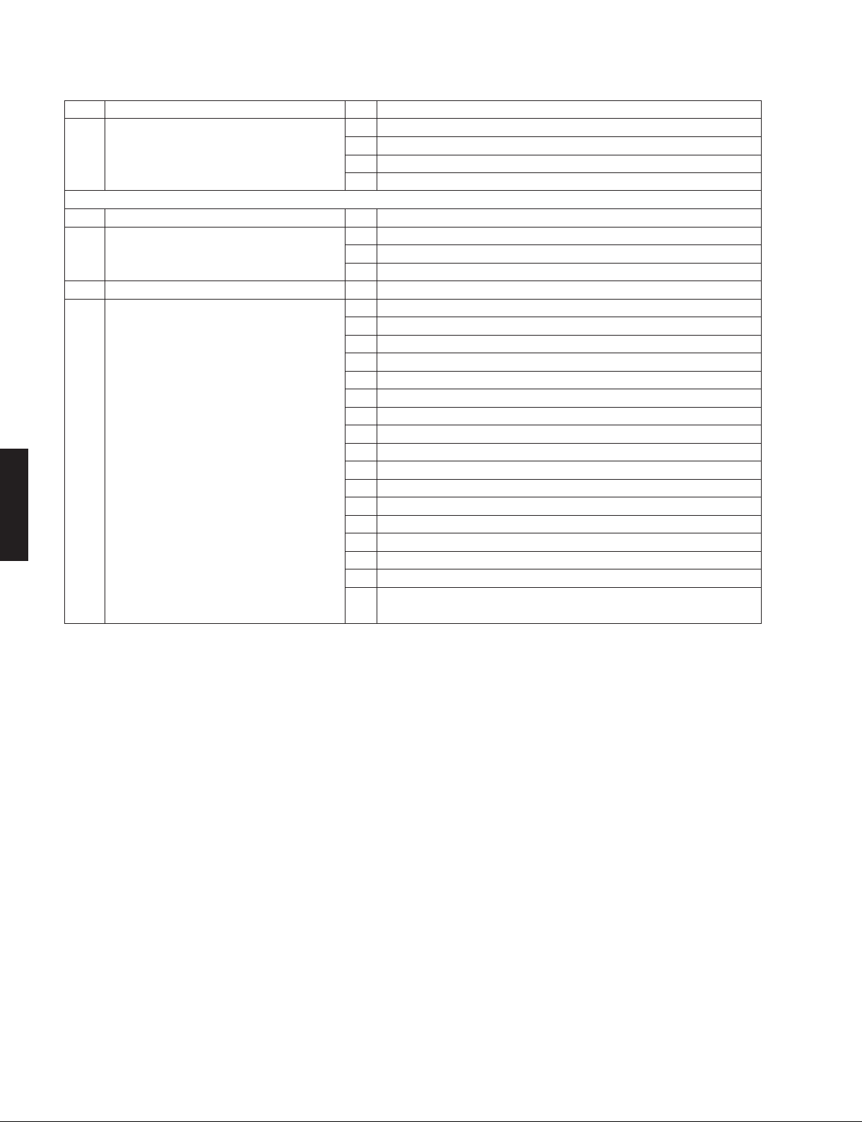
No. Main menu No. Sub-menu
A: Audio system
A1 DSP AUDIO 1 DSP MARGIN
2 DSP NON MARGIN
3 INVALID ITEM
(Not for service /
4 DSP FULL CENTER
5 DSP FULL SURROUND
6 DSP FULL SURROUND BACK
7 DSP FULL SUBWOOFER
A2 DIRECT AUDIO 1 ANALOG DIRECT VH
2 ANALOG DIRECT VL
A3 HDMI AUDIO 1 HDMI AUTO
2 INVALID ITEM
(Not for service /
3 ARC1
4 INVALID ITEM
(Not for service /
A4 SPEAKERS SET 1 BI-AMP
2 ZONE/TONE=MAX
3 ZONE/TONE=MIN
4 INVALID ITEM
5 INVALID ITEM
(Not for service /
(Not for service /
6 D-PARTY MODE
7 FULL MUTE
8 INVALID ITEM
9 INVALID ITEM
10 INVALID ITEM
(Not for service /
(Not for service /
(Not for service /
A5 MULTI CHANNEL INPUT 1 8 CHANNEL INPUT 8 ohms
(Not for service /
サービスでは使用しません
)
2 8 CHANNEL INPUT 6 ohms
A6 MIC CHECK 1 MIC ROUTE CHECK
A7 MANUAL TEST 1 TEST ALL
2 TEST FRONT L
3 TEST CENTER
4 TEST FRONT R
5 TEST SURROUND R
6 TEST SURROUND BACK R
7 TEST SURROUND BACK L
8 TEST SURROUND L
9 TEST FRONT PRESENCE L
10 TEST FRONT PRESENCE R
11 INVALID ITEM
12 INVALID ITEM
(Not for service /
(Not for service /
13 TEST LFE 1
14 INVALID ITEM
(Not for service /
サービスでは使用しません
サービスでは使用しません
サービスでは使用しません
サービスでは使用しません
サービスでは使用しません
サービスでは使用しません
サービスでは使用しません
サービスでは使用しません
サービスでは使用しません
サービスでは使用しません
サービスでは使用しません
)
RX-V771
)
)
)
)
)
)
)
)
)
)
19
RX-V771
RX-V771
No. Main menu No. Sub-menu
D: Display system
D1 FL CHECK 1 FL CHECK
2 ALL SEGMENT OFF
3 ALL SEGMENT ON
4 CHECK PATTERN 1
5 CHECK PATTERN 2
Z: Zone system
Z1 ZONE TEST 1 AV1
2AV2
3AV3
4AV4
5AV5
6AV6
(Not for service /
(Not for service /
(Not for service /
(Not for service /
(Not for service /
(Not for service /
7 AUDIO1
8 AUDIO2
9 V-AUX
10 PHONO
R: Radio and satellite broadcasting system
R1 SIRIUS (U model) 1 SIRIUS
(Not for service /
サービスでは使用しません
)
2SR
3 SSP
4 MAC
5 ADP
6 PRDID
7 SEQID
8 POWER OFF
U: Universal system
U1 iPod 1 DOCK CHECK
U2 USB 1 BF TEST 1kHz
2 BF TEST 20Hz
3 BF TEST 20kHz
(Not for service /
(Not for service /
4 USB FRONT 1 TRACK
5 USB FRONT 2 TRACK
N: Network system
N1 NETWORK 1 IP ADDRESS CHECK
2 MAC ADDRESS CHECK
3 LINE NOISE 10
4 LINE NOISE 100
(Not for service /
(Not for service /
5 EXT TEST
6 MAC ADDRESS
C: Communication system
C1 DIGITAL PCB CHECK 1 ALL
2 BUS FLASH ROM
3 BUS FPGA
4 I2C
5 FPGA RAM
6 BUS DIR
7 BUS DSP1
8 EEPROM
9 INVALID ITEM
(Not for service /
10 LINK CHECK
11 PHY TEST
サービスでは使用しません
サービスでは使用しません
サービスでは使用しません
サービスでは使用しません
サービスでは使用しません
サービスでは使用しません
サービスでは使用しません
サービスでは使用しません
サービスでは使用しません
サービスでは使用しません
サービスでは使用しません
)
)
)
)
)
)
)
)
)
)
)
20
No. Main menu No. Sub-menu
C1 DIGITAL PCB CHECK 12 I2C EEPROM
13 BUS RAM
14 SYNC SERIAL
15 CLOCK GENERATION
16 APL ID CHECK
C2 INVALID ITEM
(Not for service /
サービスでは使用しません
)
C3 HDMI INFORMATION 1 HDMI MODEL NAME
2 HDMI ID
V: Video system
V1 ANALOG VIDEO CHECK
1 ANALOG BYPASS
2 DIGITAL BYPASS
3 INVALID ITEM
(Not for service /
4 MUTE CHECK
5 TEST PATTERN
6 VIDEO IN
V2 DIGITAL VIDEO CHECK 1 LOOPBACK TEST 1
2 LOOPBACK TEST 2
3 INVALID ITEM
(Not for service /
4 HDMI REPEAT
5 DIGITAL CVBS
6 DIGITAL Y/C (B, G, F models)
7 DIGITAL COMPONENT
8 DIGITAL COMPONENT SC
9 GUI-VIDEO OUT
V3 TEST PATTERN 1 480i
2 480p
3 720p 60Hz
4 1080i 60Hz
5 1080p 60Hz
6 576i
7 576p
8 720p 50Hz
9 1080i 50Hz
10 1080p 50Hz
11 1080p 24bit
12 1080p 24bit 3D/FP
13 720p 60Hz 3D/FP
14 720p 50Hz 3D/FP
15 1080i 60Hz 3D/SS
16 1080i 50Hz 3D/SS
17 720p 60Hz 3D/TB
18 720p 50Hz 3D/TB
19 1080p 24bit 3D/TB
P: Power and protection system
P1 SYSTEM MONITOR 1 DC
2 PS1/PS2
3TM
4 INVALID ITEM
(Not for service /
5 OUTPUT LEVEL
6 LIMITER CONTROL
7 L3 (J model)
8 KEY1/KEY2
RX-V771
サービスでは使用しません
サービスでは使用しません
サービスでは使用しません
)
)
RX-V771
)
21
RX-V771
RX-V771
No. Main menu No. Sub-menu
P2 PROTECTION HISTORY 1 HISTORY 1
2 HISTORY 2
3 HISTORY 3
4 HISTORY 4
S: System and version system
S1 FIRMWARE UPDATE 1 F/W UPDATE
(Not for service /
S2 SET INFORMATION 1 MODEL
2 DESTINATION
3 DEBUG
(Not for service /
S3 FACTORY PRESET 1 PRESET INH/RSRV
S4 ROM VERSION/CHECKSUM 1 SYSTEM VERSION
2 MICROPROCESSOR VERSION
3 MICROPROCESSOR CHECKSUM
4 FLASH ROM VERSION
5 FLASH ROM CHECKSUM
6 BF VERSION
7 BF CHECKSUM
8 DSP1 VERSION
9 DSP1 CHECKSUM
10 INVALID ITEM
11 INVALID ITEM
(Not for service /
(Not for service /
12 GUI VERSION
13 FPGA GUI VERSION
14 FPGA IP VERSION
15 SIRIUS VERSION (U model)
16 INVALID ITEM
(Not for service /
(Not for service /
17 HD RADIO VERSION (U model)
(Not for service /
サービスでは使用しません
サービスでは使用しません
サービスでは使用しません
サービスでは使用しません
サービスでは使用しません
サービスでは使用しません
サービスでは使用しません
)
)
)
)
)
)
)
22

RX-V771
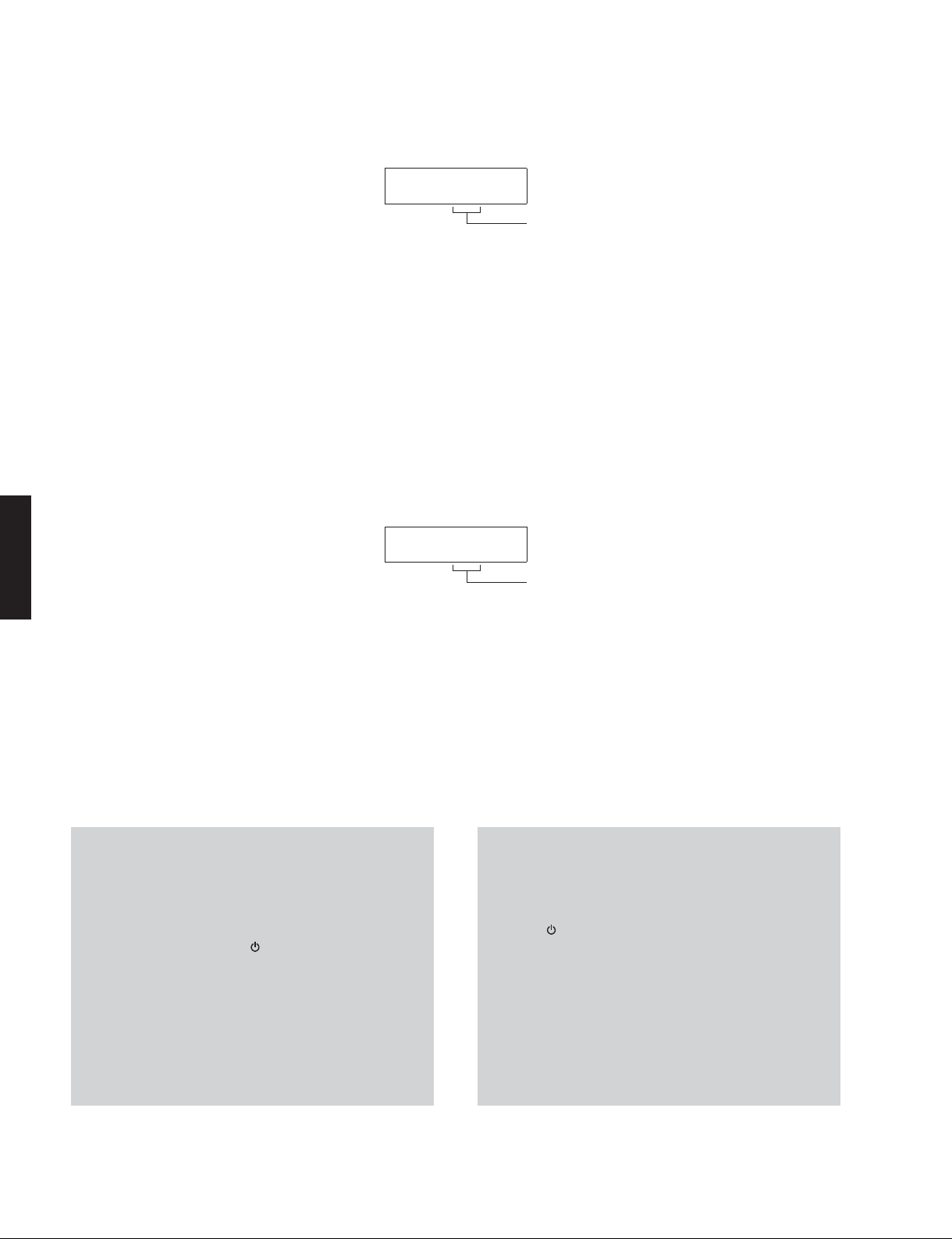
● Starting Self-Diagnostic Function
While pressing the “TONE CONTROL” and “INFO” keys,
press the “MAIN ZONE
The self-diagnostic function mode is activated.
” key to turn on the power.
Keys of this unit /
● ダイアグの起動
“TONECONTROL” と “INFO” キーを押しながら “MAIN
ZONE
ダイアグが起動します。
” キーを押して電源を入れます。
本機キー
While pressing these keys, turn on the power.
これらのキーを押しながら、電源を入れます。
RX-V771
● Starting Self-Diagnostic Function in the protection cancel mode
If the protection function works and causes hindrance to
trouble shoot, cancel the protection function as described
below, and it will be possible to enter the self-diagnostic
function mode. (The protection functions other than the
excess current detect function will be disabled.)
While pressing the “TONE CONTROL” and “INFO” keys,
press the “MAIN ZONE
keep pressing those 2 keys for 3 seconds or longer.
The self-diagnostic function mode is activated with the
protection functions disabled.
In this mode, the “SLEEP” segment of the FL display flashes
to indicate that the mode is self-diagnostic function mode
with the protection functions disabled.
CAUTION!
Using this product with the protection function disabled
may cause further damage to this unit. Use special care
for this point when using this mode.
” key to turn on the power and
●プロテクション解除モードでの起動
プロテクションが動作することにより、故障箇所の診断
に支障をきたすような場合は、次の方法によりプロテク
ションを解除した状態でダイアグモードに入ることがで
きます。(過電流検出以外のプロテクション動作を解除す
る)
“TONECONTROL” と “INFO” キーを押しながら “MAIN
ZONE
上押し続けます。
プロテクション解除モードでダイアグが起動します。
このモードでは FL の “SLEEP” セグメントが点滅し、プロ
テクションを解除した状態でのダイアグモードであるこ
とを知らせます。
注意!
プロテクションを解除した状態でのダイアグモードは、
危険な状態でもプロテクションが作動しないため、動作
させると、本機を破壊することがあります。このモード
を使用する場合は十分注意してください。
” キーを押して電源を入れ、2 つのキーを 3 秒以
23
RX-V771
● Canceling Self-Diagnostic Function
1. Before canceling self-diagnostic function, execute
setting for “S3. FACTORY PRESET” menu. (Memory
initialization inhibited or Memory initialized).
* In order to keep the user memory preserved, be
sure to select PRESET INHIBIT (Memory initialization
inhibited).
2. Press the “MAIN ZONE
” key to turn off the power.
● Display provided when Self-Diagnostic Function started
The display is as described below depending on the
situation the last time the power to this unit is turned off.
1. When the power is turned off by usual operation:
“NO PROTECT” is displayed. “A1-1. DSP MARGIN”
menu is displayed in a few seconds.
● ダイアグの解除
1. ダイアグを解除する前に、“S3.FACTORYPRESET” メ
ニュー(メモリーの初期化禁止/またはメモリーの
初期化)の設定をします。
※ ユーザーメモリーを保持したい場合は、必ず
PRESETINHIBIT(メモリー初期化禁止)を選択し
てください。
2. “MAINZONE
” キーを押して電源を切ります。
● ダイアグ起動時の表示
最後に本機の電源が切れたときの状況により、下記のよ
うに表示されます。
1. 通常の操作で電源を切った場合:
“NOPROTECT” が表示されます。数秒後、“A1-1DSP
MARGIN” メニューが表示されます。
RX-V771
Opening message /
NOPROTECT
オープニング表示
After a few seconds /
Main menu display /
数秒後
メインメニュー表示
A1-1
DSPMARGIN
24
RX-V771
2. When the protection function worked to turn
off the power:
The data of protection function which worked at the
moment is displayed. Then “A1-1. DSP MARGIN” menu
is displayed in a few seconds.
Note: At that time if you reactivate the self-diagnostic
function after turning off the power once
by pressing the “MAIN ZONE
PROTECT” will be displayed because that
situation is equal to “1. When the power is
turned off by usual operation:” described above.
However the protection function history is stored
in a back-up IC with a backup. For details, refer
to “P2 PROTECTION HISTORY” menu.
2-1. When there is a history of protection function
due to excess current.
Cause: An excessive current flowed through the power
amplifier.
Supplementary information: As over current of the
power amplifier is detected, check condition of each
power transistor.
Turning on the power without correcting the abnormality
will cause the protection function to work immediately and
the power supply will instantly be shut off.
” key, “NO
IPROTECT
2. プロテクションが働いて電源が切れた場合:
そのときに働いたプロテクションの情報が表示され
ます。数秒後、“A1-1 DSPMARGIN” メニューが表示
されます。
注) このときに “MAIN ZONE
たん電源を切った後にダイアグを再起動する
と、前述の「1.通常の操作で電源を切った場合」
に相当するので、“NOPROTECT” が表示されま
す。
ただし、プロテクションの履歴はメモリーに
バックアップして記憶されます。詳細は、“P2
PROTECTIONHISTORY” メニューを参照してく
ださい。
2-1. 過電流によるプロテクション履歴がある場合
原因:パワーアンプに過電流が流れた。
補足:パワーアンプの過電流を検出していますので、各
パワートランジスタの状態を確認してください。
異常状態のまま電源を入れると、瞬時にプロテクション
が働き、すぐに電源が切れます。
” キーを押していっ
RX-V771
Notes)
• Applying the power to this unit without correcting
the abnormality can be dangerous and cause
additional circuit damage. To avoid this, if “I
PROTECT” protection function works 1 time,
the power will not turn on even when the “MAIN
ZONE
power again, start up the self-diagnostic function.
• The output transistors in each amplifier channel
should be checked for damage before applying
power to this unit.
• Amplifier current should be monitored by
measuring DC voltage across the emitter resistors
for each channel.
” key is pressed. In order to turn on the
注意!
・ 異常状態のまま本機の電源を入れると、危険な状態
になり、さらに回路が損傷を受ける原因になります。
それを避けるために、「IPROTECT」が1回働いた場
合、それ以降 “MAINZONE
が入らなくなります。再度電源を入れる場合、ダイ
アグを起動してください。
・ 本機の電源をいれる前に、各パワーアンプの出力ト
ランジスタに損傷がないかチェックしてください。
・ パワーアンプの電流は、各チャンネルのエミッター
の抵抗器間 DC 電圧を測定することによりモニター
してください。
” キーを押しても電源
25
RX-V771
RX-V771
2-2. When the protection function worked due to
abnormal DC output.
DCPRT:xxxH
Cause: DC output of the power amplifier is abnormal.
Supplementary information: The protection function
worked due to a DC voltage appearing at the speaker
terminal. A cause could be a defect in the amplifier.
Turning on the power without correcting the abnormality
will cause the protection function to work in 5 seconds
and the power supply will be shut off.
2-3. When the protection function worked due to
abnormal voltage in the power supply section.
PSPRT:xxxL
2-2. DC出力異常によりプロテクションが働いた場合
AD conversion value when the protection function is working
プロテクションが働いたときの電圧の A/D 変換値
原因:パワーアンプのDC 出力が異常。
補足:アンプの故障でスピーカー端子に直流電圧が掛か
るなどが原因で、プロテクションが働いたことを
示します。
異常状態のまま電源を入れると、5 秒後にプロテクション
が働き、電源が切れます。
2-3. 電源部の電圧異常によりプロテクションが働い
た場合
AD conversion value when the protection function is working
プロテクションが働いたときの電圧の A/D 変換値
Cause: The voltage in the power supply section is
abnormal.
Supplementary information: The protection function
worked due to a defect or overload in the power supply.
Turning on the power without correcting the abnormality
will cause the protection function to work in 1 seconds
and the power supply will be shut off.
Notes)
• Applying the power to this unit without correcting
the abnormality can be dangerous and cause
additional circuit damage. To avoid this, if “PS”
and “DC” protection function works 3 times
consecutively, the power will not turn on even
when the “MAIN ZONE
to turn on the power again, start up the selfdiagnostic function.
• The output transistors in each amplifier channel
should be checked for damage before applying
power to this unit.
• Amplifier current should be monitored by
measuring DC voltage across the emitter resistors
for each channel.
” key is pressed. In order
原因:電源部の電圧が異常。
補足:電源電圧による原因で、プロテクションが働いた
ことを示します。
異常状態のまま電源を入れると、1 秒後にプロテクション
が働き、電源が切れます。
注意!
・ 異常状態のまま本機の電源を入れると、危険な状態
になり、さらに回路が損傷を受ける原因になりま
す。それを避けるために、「DC」、「PS」プロテクショ
ンが連続して 3 回目働いた場合、それ以降 “MAIN
ZONE
再度電源を入れる場合、ダイアグを起動してくださ
い。
・ 本機の電源をいれる前に、各パワーアンプの出力ト
ランジスタに損傷がないかチェックしてください。
・ パワーアンプの電流は、各チャンネルのエミッター
の抵抗器間 DC 電圧を測定することによりモニター
してください。
” キーを押しても電源が入らなくなります。
26

RX-V771
2-4. When the protection function worked due to
excessive heatsink temperature.
TMP1PRT:xxxL
Cause: The temperature of the heatsink is excessive.
Supplementary information: The protection function
worked due to the temperature limit being exceeded.
Causes could be poor ventilation or a defect related to
the thermal sensor.
Turning on the power without correcting the abnormality
will cause the protection function to work in 1 seconds
and the power supply will be shut off.
● History of protection function
When the protection function has worked, its history
is stored in memory with a backup.
Even if no abnormality is noted while servicing the
unit, an abnormality which has occurred previously
can be defined as long as the backup data has been
stored.
For details, refer to “P2 PROTECTION HISTORY”
menu.
2-4. ヒートシンクの異常温度によりプロテクション
が働いた場合
AD conversion value when the protection function is working
プロテクションが働いたときの電圧の A/D 変換値
原因:ヒートシンクの温度が異常。
補足:温度制限を越えた原因で、プロテクションが働い
たことを示します。
異常状態のまま電源を入れると、1 秒後にプロテクション
が働き、電源が切れます。
RX-V771
● プロテクションの履歴
プロテクションが働いた場合、その履歴をバックアッ
プして記憶しています。
修理のときに異常が認められなくても、バックアッ
プが残っていれば、お客様のところで起きた異常を
区別できます。
詳細は、“P2PROTECTION HISTORY” メニューを参照
してください。
27
RX-V771
RX-V771
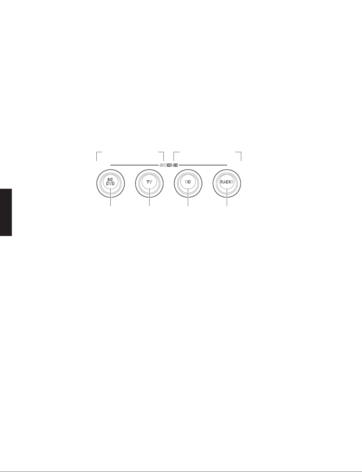
● Operation procedure of Main menu and Sub-menu
There are 25 main menu items, each of which has submenu items.
Main menu selection
Select the main menu using “SCENE TV” (forward) and
“SCENE BD/DVD” (reverse) keys.
Sub-menu selection
Select the sub-menu using “SCENE RADIO” (forward) and
“SCENE CD” (reverse) keys.
Keys of this unit /
Main menu selection
メインメニューの選 択
Reverse
逆送り
Forward
順送り
● メインメニューとサブメニューの操作
ダイアグには 25 個のメインメニューがあり、そのそれぞ
れにサブメニューがあります。
メインメニューの選択
“SCENETV”(順送り)、“SCENEBD/DVD”(逆送り)キー
で選択します。
サブメニューの選択
“SCENERADIO”(順送り)、“SCENECD”(逆送り)キーで
選択します。
本機キー
Sub-menu selection
サブメニュー の選 択
Reverse
逆送り
Forward
順送り
● Functions in Self-Diagnostic Function mode
In addition to the self-diagnostic function menu items,
functions as listed below are available.
• Power ON/OFF
• Master volume
• Muting
• Input selection
• Zone control
* Functions related to the tuner and the set menu are
not available.
● Initial settings when Self-Diagnostic Function started
The following initial settings are used when starting selfdiagnostic function.
When self-diagnostic function is canceled, these settings
are restored to those before starting self-diagnostic
function.
• Master volume: -20 dB / Zone volume: +2.5dB
• Input: HDMI1 / Zone input: AUDIO1
• Main menu: A1-1. DSP MARGIN
• Speaker setting: LARGE, Bass out to SWFR
(All channels)
• HDMI Control: Off
• Zone 2: On
28
● ダイアグ中の機能
ダイアグメニューの他に、以下の機能が動作します。
・ 電源 オン/オフ
・ マスターボリューム
・ ミューティング
・ インプットセレクト
・ ZONE コントロール
※ チューナー関連、セットメニュー関連は機能しません。
● ダイアグ開始時の初期設定
ダイアグ開始時に以下のような設定になります。
ダイアグ解除時にはダイアグ開始前の状態に戻ります。
・ マスターボリューム: -20dB
・ インプット: HDMI1 / ZONE インプット:
AUDIO1
・ メインメニュー: A1-1.DSPMARGIN
・ スピーカー設定: LARGE、BassouttoSWFR
(すべてのチャンネル)
・ HDMI コントロール: OFF

RX-V771
● Details of Self-Diagnostic Function menu
A1. DSP AUDIO
This menu is used to check audio signal route via
DSP.
A1-1. DSP MARGIN
The audio signal is output including the head
margin via DSP.
* When input source is stereo, signal is
assigned as below.
Front L: Front L, Center, Surround L,
Surround Back L
Front R: Front R, Surround R, Surround
Back R
Front L +10 dB: Subwoofer
A1-1
DSPMARGIN
● ダイアグメニュー詳細
A1.DSPAUDIO
DSP を経由するオーディオ信号経路をチェックしま
す。
A1-1. DSPMARGIN
音声信号が DSP を経由してヘッドマージンを
含んで出力されます。
※2ch 信号入力時、以下のように信号が振り
分けられて出力されます。
FrontL: FrontL、Center、SurroundL、
SurroundBackL
FrontR: FrontR、SurroundR、 Surround
BackR
FrontL+10dB:Subwoofer
RX-V771
A1-2. DSP NON MARGIN
The SUBWOOFER signal is output including
the head margin via DSP.
The audio signal other than SUBWOOFER is
output without including the head margin via
DSP.
A1-3. INVALID ITEM
Not for service.
A1-4. DSP FULL CENTER
The audio signal is output to only CENTER
channel in digital full bit without including the
head margin.
A1-2. DSPNONMARGIN
サブウーファーの音声信号が DSP を経由して
ヘッドマージンを含んで出力されます。
サブウーファー以外の音声信号は DSP を経由
してヘッドマージンを含まず出力されます。
A1-2
DSPNONMARGIN
A1-3. INVALIDITEM
サービスでは使用しません
A1-3
INVALIDITEM
A1-4. DSPFULLCENTER
音声信号がヘッドマージンを含まず、デジタ
ルフルビットで CENTER チャンネルのみへ出
力されます。
A1-4
DSPFULLC
29
RX-V771
RX-V771
A1-5. DSP FULL SURROUND
The audio signal is output to only SURROUND
L/R channels in digital full bit without including
the head margin.
A1-6. DSP FULL SURROUND BACK
The audio signal is output to only SURROUND
BACK L/R channels in digital full bit without
including the head margin.
A1-7. DSP FULL SUBWOOFER
The audio signal is output to only SUBWOOFER
channels in digital full bit without including the
head margin.
A1-5. DSPFULLSURROUND
音声信号がヘッドマージンを含まず、デジタ
ルフルビットで SURROUND L/R チャンネルの
みへ出力されます。
A1-5
DSPFULLSUR
A1-6.DSPFULLSURROUNDBACK
音声信号がヘッドマージンを含まず、デジタ
ルフルビットで SURROUNDBACKL/R チャン
ネルのみへ出力されます。
A1-6
DSPFULLSB
A1-7.DSPFULLSUBWOOFER
音声信号がヘッドマージンを含まず、デジタ
ルフルビットで SUBWOOFER チャンネルのみ
へ出力されます。
A2. DIRECT AUDIO
This menu is used to check audio signal route of
DIRECT mode.
A2-1. DIRECT VH
The analog input audio signal is output to
FRONT L/R in PURE DIRECT mode.
VH: Voltage High, RY101 on MAIN P.C.B.: Off
INPUT: AV5 ANALOG
SPEAKER OUT: 1 kHz, SUBWOOFER OUTPUT: 50 Hz
A1-7
DSPFULLSW
A2.DIRECTAUDIO
DIRECT モードのオーディオ信号経路をチェックしま
す。
A2-1. DIRECTVH
アナログ入力の音声信号が PUREDIRECT で
FRONTL/R へ出力されます。
VH:VoltageHigh、
MAINP.C.B. の RY101:Off
A2-1
DIRECT:VH
SPEAKER OUTPUT
Input level Volume
Both ch, -20 dBm +6.5 dB +13.0 dBm - ∞ - ∞ - ∞ - ∞ - ∞
FRONT L/R CENTER
SURROUND
L/R
SURROUND
BACK L/R
PRESENCE/
ZONE2
30
SUBWOOFER
OUTPUT
 Loading...