

Page 1

Receiver
U
OWNER’S MANUAL
Page 2
IMPORTANT SAFETY INSTRUCTIONS
IMPORTANT SAFETY INSTRUCTIONS
CAUTION
RISK OF ELECTRIC SHOCK
DO NOT OPEN
CAUTION: TO REDUCE THE RISK OF
ELECTRIC SHOCK, DO NOT REMOVE
COVER (OR BACK). NO USER-SERVICEABLE
PARTS INSIDE. REFER SERVICING TO
QUALIFIED SERVICE PERSONNEL.
• Explanation of Graphical Symbols
The lightning flash with arrowhead symbol, within
an equilateral triangle, is intended to alert you to the
presence of uninsulated “dangerous voltage” within
the product’s enclosure that may be of sufficient
magnitude to constitute a risk of electric shock to
persons.
The exclamation point within an equilateral triangle
is intended to alert you to the presence of important
operating and maintenance (servicing) instructions
in the literature accompanying the appliance.
IMPORTANT
Please record the serial number of this unit in the space
below.
MODEL:
Serial No.:
The serial number is located on the rear of the unit. Retain
this Owner’s Manual in a safe place for future reference.
1 Read these instructions.
2 Keep these instructions.
3 Heed all warnings.
4 Follow all instructions.
5 Do not use this apparatus near water.
6 Clean only with dry cloth.
7 Do not block any ventilation openings. Install in
accordance with the manufacturer’s instructions.
8 Do not install near any heat sources such as radiators,
heat registers, stoves, or other apparatus (including
amplifiers) that produce heat.
9 Do not defeat the safety purpose of the polarized or
grounding-type plug. A polarized plug has two blades
with one wider than the other. A grounding type plug has
two blades and a third grounding prong. The wide blade
or the third prong are provided for your safety. If the
provided plug does not fit into your outlet, consult an
electrician for replacement of the obsolete outlet.
10 Protect the power cord from being walked on or pinched
particularly at plugs, convenience receptacles, and the
point where they exit from the apparatus.
11 Only use attachments/accessories specified by the
manufacturer.
12 Use only with the cart, stand, tripod,
bracket, or table specified by the
manufacturer, or sold with the apparatus.
When a cart is used, use caution when
moving the cart/apparatus combination to
avoid injury from tip-over.
13 Unplug this apparatus during lightning storms or when
unused for long periods of time.
14 Refer all servicing to qualified service personnel.
Servicing is required when the apparatus has been
damaged in any way, such as power-supply cord or plug
is damaged, liquid has been spilled or objects have fallen
into the apparatus, the apparatus has been exposed to rain
or moisture, does not operate normally, or has been
dropped.
We Want You Listening For A Lifetime
Yamaha and the Electronic Industries Association’s Consumer Electronics Group want you to get the most out of your
equipment by playing it at a safe level. One that lets the sound come through loud and clear without annoying blaring or
distortion – and, most importantly, without affecting your sensitive hearing. Since hearing damage from loud sounds is
often undetectable until it is too late, Yamaha and the Electronic Industries Association’s Consumer Electronics Group
recommend you to avoid prolonged exposure from excessive volume levels.
i En
Page 3

FCC INFORMATION (for US customers)
1 IMPORTANT NOTICE: DO NOT MODIFY THIS
UNIT!
This product, when installed as indicated in the
instructions contained in this manual, meets FCC
requirements. Modifications not expressly approved by
Yamaha may void your authority, granted by the FCC,
to use the product.
2 IMPORTANT:
accessories and/or another product use only high quality
shielded cables. Cable/s supplied with this product MUST
be used. Follow all installation instructions. Failure to
follow instructions could void your FCC authorization to
use this product in the USA.
When connecting this product to
3 NOTE: This product has been tested and found to comply
with the requirements listed in FCC Regulations, Part 15
for Class “B” digital devices. Compliance with these
requirements provides a reasonable level of assurance that
your use of this product in a residential environment will
not result in harmful interference with other electronic
devices.
This equipment generates/uses radio frequencies and,
if not installed and used according to the instructions
found in the users manual, may cause interference
harmful to the operation of other electronic devices.
IMPORTANT SAFETY INSTRUCTIONS
Compliance with FCC regulations does not guarantee
that interference will not occur in all installations. If
this product is found to be the source of interference,
which can be determined by turning the unit “OFF”
and “ON”, please try to eliminate the problem by using
one of the following measures:
Relocate either this product or the device that is being
affected by the interference.
Utilize power outlets that are on different branch
(circuit breaker or fuse) circuits or install AC line
filter/s.
In the case of radio or TV interference, relocate/
reorient the antenna. If the antenna lead-in is 300 ohm
ribbon lead, change the lead-in to coaxial type cable.
If these corrective measures do not produce
satisfactory results, please contact the local retailer
authorized to distribute this type of product. If you can
not locate the appropriate retailer, please contact
Yamaha Electronics Corp., USA 6660 Orangethorpe
Ave., Buena Park, CA 90620.
The above statements apply ONLY to those products
distributed by Yamaha Corporation of America or its
subsidiaries.
ii En
Page 4
CAUTION: READ THIS BEFORE OPERATING YOUR UNIT.
CAUTION: READ THIS BEFORE OPERATING YOUR UNIT.
1 To assure the finest performance, please read this manual
carefully. Keep it in a safe place for future reference.
2 Install this sound system in a well ventilated, cool, dry,
clean place - away from direct sunlight, heat sources,
vibration, dust, moisture, and/or cold. For proper
ventilation, allow the following minimum clearances
around this unit.
Top: 30 cm (11-3/4 in)
Rear: 20 cm (7-7/8 in)
Sides: 20 cm (7-7/8 in)
3 Locate this unit away from other electrical appliances,
motors, or transformers to avoid humming sounds.
4 Do not expose this unit to sudden temperature changes
from cold to hot, and do not locate this unit in an
environment with high humidity (i.e. a room with a
humidifier) to prevent condensation inside this unit,
which may cause an electrical shock, fire, damage to this
unit, and/or personal injury.
5 Avoid installing this unit where foreign object may fall
onto this unit and/or this unit may be exposed to liquid
dripping or splashing. On the top of this unit, do not
place:
– Other components, as they may cause damage and/or
discoloration on the surface of this unit.
– Burning objects (i.e. candles), as they may cause fire,
damage to this unit, and/or personal injury.
– Containers with liquid in them, as they may fall and
liquid may cause electrical shock to the user and/or
damage to this unit.
6 Do not cover this unit with a newspaper, tablecloth,
curtain, etc. in order not to obstruct heat radiation. If the
temperature inside this unit rises, it may cause fire,
damage to this unit, and/or personal injury.
7 Do not plug in this unit to a wall outlet until all
connections are complete.
8 Do not operate this unit upside-down. It may overheat,
possibly causing damage.
9 Do not use force on switches, knobs and/or cords.
10 When disconnecting the power cable from the wall outlet,
grasp the plug; do not pull the cable.
11 Do not clean this unit with chemical solvents; this might
damage the finish. Use a clean, dry cloth.
12 Only voltage specified on this unit must be used. Using
this unit with a higher voltage than specified is dangerous
and may cause fire, damage to this unit, and/or personal
injury. Yamaha will not be held responsible for any
damage resulting from use of this unit with a voltage
other than specified.
13 To prevent damage by lightning, keep the power cable
and outdoor antennas disconnected from a wall outlet or
this unit during a lightning storm.
14 Do not attempt to modify or fix this unit. Contact
qualified Yamaha service personnel when any service is
needed. The cabinet should never be opened for any
reasons.
15 When not planning to use this unit for long periods of
time (i.e. vacation), disconnect the AC power plug from
the wall outlet.
16 Be sure to read the “TROUBLESHOOTING” section on
common operating errors before concluding that this unit
is faulty.
17 Before moving this unit, press A to set this unit to the
standby mode, and disconnect the AC power plug from
the wall outlet.
18 Condensation will form when the surrounding
temperature changes suddenly. Disconnect the power
cable from the outlet, then leave this unit alone.
19 When using this unit for a long time, this unit may
become warm. Turn the power off, then leave this unit
alone for cooling.
20 Install this unit near the AC outlet and where the AC
power plug can be reached easily.
21 The batteries shall not be exposed to excessive heat such
as sunshine, fire or the like.
22 Excessive sound pressure from earphones and
headphones can cause hearing loss.
As long as this unit is connected to the AC wall outlet, it is not
disconnected from the AC power source even if you set this unit to
standby mode by A. In this state, this unit is designed to consume a
very small quantity of power.
WARNING
TO REDUCE THE RISK OF FIRE OR ELECTRIC SHOCK, DO
NOT EXPOSE THIS UNIT TO RAIN OR MOISTURE.
CAUTION
Danger of explosion if battery is incorrectly replaced.
Replace only with the same or equivalent type.
This label is required to be attached to a product of which
the temperature of the top cover may be hot during
operation.
iii En
Page 5

CONTENTS
INTRODUCTION
USEFUL FEATURES ............................................ 2
SUPPLIED ACCESSORIES ................................. 3
CONTROLS AND FUNCTIONS ......................... 4
Front panel ................................................................. 4
Front panel display .................................................... 6
Rear panel .................................................................. 7
Remote control........................................................... 8
Zone 2 remote control (R-S700 only) ...................... 10
Using the remote controls ........................................ 11
PREPARATION
CONNECTIONS .................................................. 12
Connecting speakers and source components..........12
Connecting the FM and AM antennas ..................... 14
Using COUPLER jacks (R-S700 only) ................... 15
Connecting power cable .......................................... 15
BASIC OPERATION
PLAYING AND RECORDING .......................... 16
Playing a source....................................................... 16
Adjusting the tonal quality....................................... 17
Recording a source .................................................. 19
Using the sleep timer ............................................... 19
FM/AM TUNING ................................................. 20
Automatic tuning ..................................................... 20
Manual tuning .......................................................... 21
Automatic station preset (FM stations only) ........... 22
Manual station preset ............................................... 23
Recalling a preset station ......................................... 24
Clearing a preset station........................................... 24
Clearing all preset stations....................................... 25
LISTENING TO SIRIUS Satellite Radio™....... 26
Connecting the SiriusConnect™ tuner .................... 27
Activating SIRIUS Satellite Radio™
subscription ......................................................... 27
SIRIUS Satellite Radio™ operations ...................... 28
Registering and recalling SIRIUS
Satellite Radio™ channels .................................. 30
Setting the Parental Lock......................................... 32
Displaying the SIRIUS Satellite Radio™
information .......................................................... 34
PLAYING BACK TUNES
FROM YOUR iPhone/iPod/
Bluetooth™ COMPONENT ............................ 35
Using a Universal Dock for iPod ............................. 36
Using a Wireless System for iPod ........................... 37
Using a Bluetooth Wireless Audio Receiver........... 38
ADVANCED OPERATION
SETTING THE OPTION MENU
FOR EACH INPUT SOURCE.........................40
Option menu items................................................... 40
ADVANCED SETUP ............................................43
Changing the ADVANCED SETUP
menu parameters.................................................. 43
Switching the remote control ID ............................. 44
ZONE 2 ..................................................................45
Connecting Zone 2 components .............................. 45
Controlling Zone 2................................................... 46
REMOTE CONTROL FEATURES ...................47
Controlling this unit, a TV, or other components .... 47
Configuring the remote control ............................... 49
ADDITIONAL INFORMATION
TROUBLESHOOTING .......................................50
SPECIFICATIONS...............................................57
PREPARATIONINTRODUCTION
OPERATION
BASIC
OPERATION
ADVANCED
INFORMATION
ADDITIONAL
1 En
Page 6
USEFUL FEATURES
This unit allows you to:
USEFUL FEATURES
Improve sound quality by using the CD Direct Amp*1 and Pure
Direct functions
Play back music from your iPhone/iPod*2 or Bluetooth
component
Play back video content from your iPhone/iPod
Listen to SIRIUS Satellite Radio channels
*2
*1 *2
*3
Listen to FM and AM radio stations
Boost bass sounds by connecting a subwoofer
Connect an external device*1 such as a graphic equalizer or a
surround-sound processor
Use this unit’s remote control to operate other components such
as a CD player, BD/DVD player or TV
Save power by using the automatic power down function
Use this unit to listen to another input source in two different
rooms
*1
R-S700 only
*2
Optional Yamaha product required
*3
Optional SiriusConnect tuner required
➡
➡
➡
➡
➡
➡
➡
➡
➡
➡
p. 17
p. 35
p. 36
p. 26
p. 20
p. 12
p. 15
p. 47
p. 43
p. 45
SIRIUS, XM and all related marks and logos are trademarks of Sirius XM Radio Inc. and its subsidiaries. All rights
reserved. Service not available in Alaska and Hawaii.
iPhone, iPod
iPhone, iPod, iPod classic, iPod nano and iPod touch are trademarks of Apple Inc., registered in the U.S. and other
countries.
Bluetooth™
Bluetooth is a registered trademark of the Bluetooth SIG and is used by Yamaha in accordance with a license agreement.
• y indicates a tip for your operation.
• This manual is the owner’s manual for both the R-S700 and the R-S500. Model names are given where the details of functions are
unique to each model. Generally, illustrations of the R-S700 are used for explanations.
• Some operations can be performed by using either the buttons on the front panel of this unit or those on the remote controls. In case
the button names differ between this unit and the remote controls, the names of the buttons on the remote controls are given in
parentheses.
• In case the buttons on the remote control and the Zone 2 remote control have certain functions in common, the illustrations of the
buttons on the remote control are used for explanation throughout the manual.
• This manual is printed prior to production. Design and specifications are subject to change in part as a result of improvements, etc. In
case of differences between the manual and the product, the product has priority.
2 En
Page 7
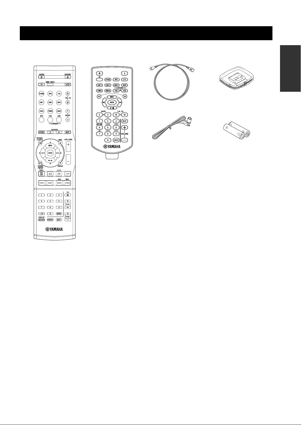
SUPPLIED ACCESSORIES
SUPPLIED ACCESSORIES
Please check that you received all of the following parts.
Remote control
Zone 2 remote control
(R-S700 only)
Power cable
(R-S700 only)
Indoor FM antenna
INTRODUCTION
AM loop antenna
Batteries (x2)
(AAA, R03, UM-4)
■ Notes on remote controls and batteries
• Do not spill water or other liquids on the remote control.
• Do not drop the remote control.
• Do not leave or store the remote control in the following conditions:
– places of high humidity, such as near a bath
– places of high temperatures, such as near a heater or stove
– places of extremely low temperatures
– dusty places
• Use AAA, R03, UM-4 batteries for the remote control.
• Use a CR2025 battery for the Zone 2 remote control (R-S700 only).
• Insert batteries according to the polarity markings (+ and -).
• Change all batteries if you notice the operation range of the remote control narrows.
• If the batteries run out, immediately remove them from the remote control to prevent an explosion or acid leak.
• If you find leaking batteries, discard the batteries immediately, taking care not to touch the leaked material. If the leaked material
comes into contact with your skin or gets into your eyes or mouth, rinse it away immediately and consult a doctor. Clean the battery
compartment thoroughly before installing new batteries.
• Do not use old batteries together with new ones. This may shorten the life of the new batteries or cause old batteries to leak.
• Do not use different types of batteries (such as alkaline and manganese batteries) together. Batteries that look the same may have a
different specification.
• Before inserting new batteries, wipe the battery compartment clean.
• Dispose of batteries according to your regional regulations.
3 En
Page 8
CONTROLS AND FUNCTIONS
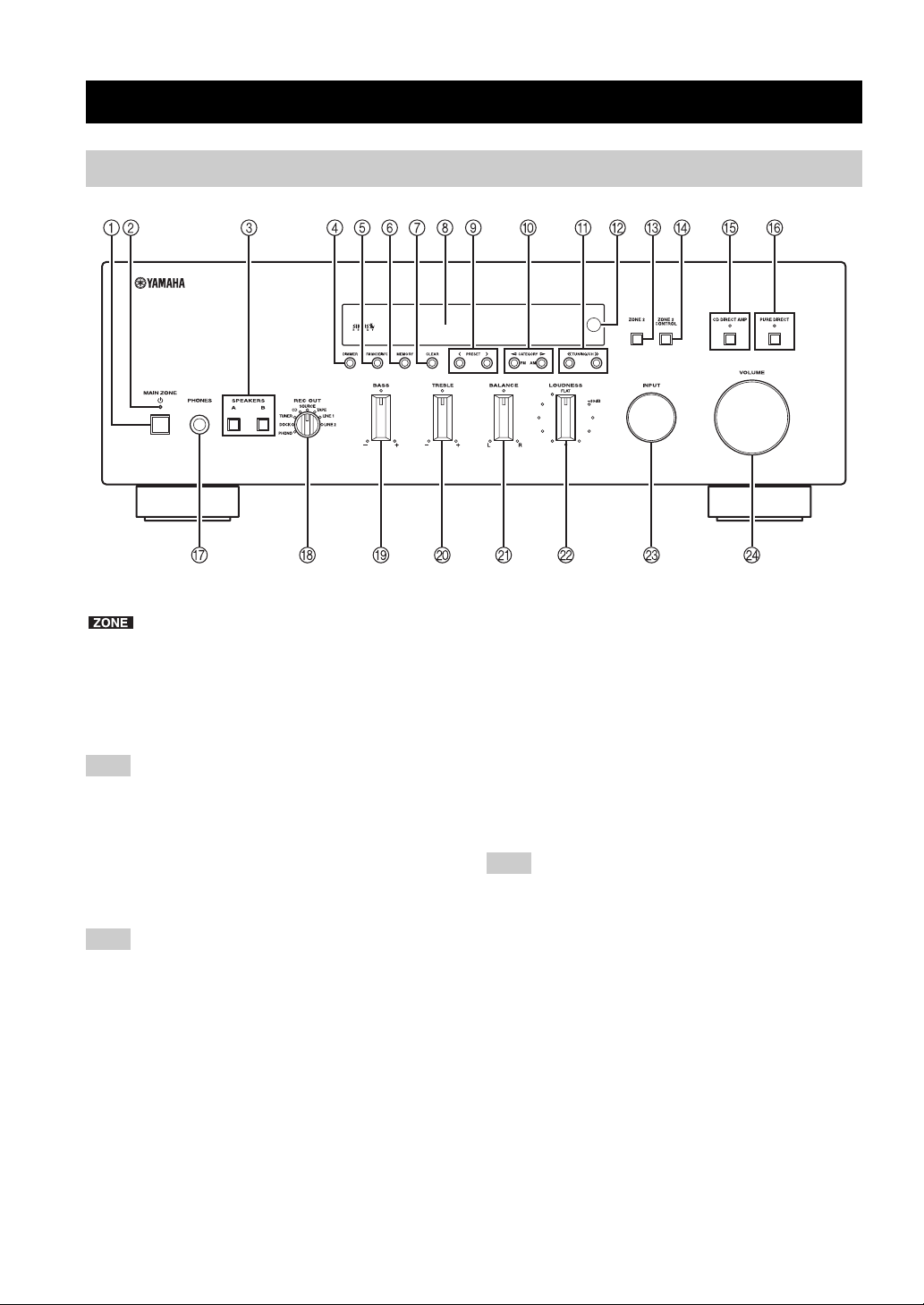
Front panel
CONTROLS AND FUNCTIONS
(R-S700)
y
indicates buttons and controls that can also be used to
control Zone 2. For more information about Zone 2, see pages 45
and 46.
1 MAIN ZONE A
Turns on this unit’s Main Zone unit or sets the Main Zone
to standby mode (see page 16).
Note
In standby mode, this unit consumes a small amount of power to
receive infrared signals from the remote control.
2 MAIN ZONE indicator
Lights up as follows:
Brightly lit: Power is on
Dimly lit: Standby mode
Note
The MAIN ZONE indicator is brightly lit while an iPhone/iPod is
charging.
3 SPEAKERS A/B
Turns on or off the speaker set connected to the
SPEAKERS A and/or SPEAKERS B terminals on the rear
panel each time the corresponding button is pressed (see
page 16).
4 DIMMER
Changes the brightness level of the front panel display.
Choose brightness from 3 levels by pressing this button
repeatedly.
y
This setting is retained even if you turn off this unit.
5 FM MODE/INFO
Changes the FM radio wave reception mode (stereo or
monaural) when TUNER is selected as the input source
(see page 21).
Changes the SIRIUS Satellite Radio information
displayed on the front panel display when SIRIUS is
selected as the input source (see page 34).
Changes the playback information displayed about the
song playing on the iPhone/iPod when DOCK is selected
as the input source (see page 36).
Note
Playback information can only be displayed for an iPhone/iPod
that is connected using a Universal Dock for iPod.
6 MEMORY
Stores the current FM/AM station as a preset when
TUNER is selected as the input source (see page 23).
Stores the current SIRIUS channel as a preset when
SIRIUS is selected as the input source (see page 30).
7 CLEAR
Clears the current FM/AM preset station when TUNER is
selected as the input source (see page 24).
Clears the current SIRIUS preset channel when SIRIUS is
selected as the input source (see page 32).
8 Front panel display
Shows information about the operational status of this
unit.
4 En
Page 9

CONTROLS AND FUNCTIONS
9 PRESET j / i
Selects a preset FM/AM station when TUNER is selected
as the input source (see page 24).
Selects a preset SIRIUS channel when SIRIUS is selected
as the input source (see page 31).
0 FM/CATEGORY l, AM/CATEGORY h
Sets the FM/AM tuner band to FM or AM when TUNER
is selected as the input source (see page 20).
Selects a channel category when SIRIUS is selected as the
input source (see page 29).
A TUNING/CH jj / ii
Selects the tuning frequency when TUNER is selected as
the input source (see page 20).
Searches for a SIRIUS channel when SIRIUS is selected
as the input source (see page 29).
B Remote control sensor
Receives infrared signals from the remote control.
Note
Switch the remote control ID between ID1 and ID2 when using
multiple Yamaha receivers or amplifiers (see page 44).
C ZONE 2
Turns on Zone 2 or sets ZONE 2 to standby mode. When
Zone 2 is turned on, signals are output to the ZONE 2
OUT jacks (see page 45).
D ZONE 2 CONTROL
Allows buttons and controls on the front panel to be used
to control Zone 2. For more information about controlling
Zone 2, see page 46.
E CD DIRECT AMP and indicator (R-S700 only)
Allows you to listen to a CD source in the purest possible
sound (see page 17). The indicator lights up and the front
panel display turns off when this function is turned on.
H REC OUT selector
Selects a source for recording to a CD recorder or to a tape
deck independently of the INPUT selector setting,
allowing you to record the selected source while listening
to another source (see page 19).
I BASS control
Increases or decreases the low frequency response. The
center position produces a flat response (see page 18).
J TREBLE control
Increases or decreases the high frequency response. The
center position produces a flat response (see page 18).
K BALANCE control
Adjusts the sound output balance of the left and right
speakers to compensate for sound imbalances caused by
speaker locations or listening room conditions (see page
18).
L LOUDNESS control
Retains a full tonal range at any volume level to
compensate for the human ears’ loss of sensitivity to high
and low-frequency ranges at a low volume level (see page
18).
M INPUT selector
Selects the input source you want to listen to.
N VOLUME control ( R-S700 only)
Increases or decreases the sound output level.
Note
This does not affect the output level of the REC jacks.
INTRODUCTION
Notes
• If both the CD DIRECT AMP and the PURE DIRECT are
turned on, only the CD DIRECT AMP will function.
• Zone 2 cannot be used while this function is turned on.
F PURE DIRECT and indicator
Allows you to listen to a source in the purest possible
sound (see page 17). The indicator above it lights up and
the front panel display turns off when this function is
turned on.
Note
Zone 2 cannot be used while this function is turned on.
G PHONES jack
Outputs audio to your headphones for private listening.
Note
Press SPEAKER A/B so that the SP A/B indicators turn off
before you connect your headphones to the PHONES jack.
5 En
Page 10
CONTROLS AND FUNCTIONS
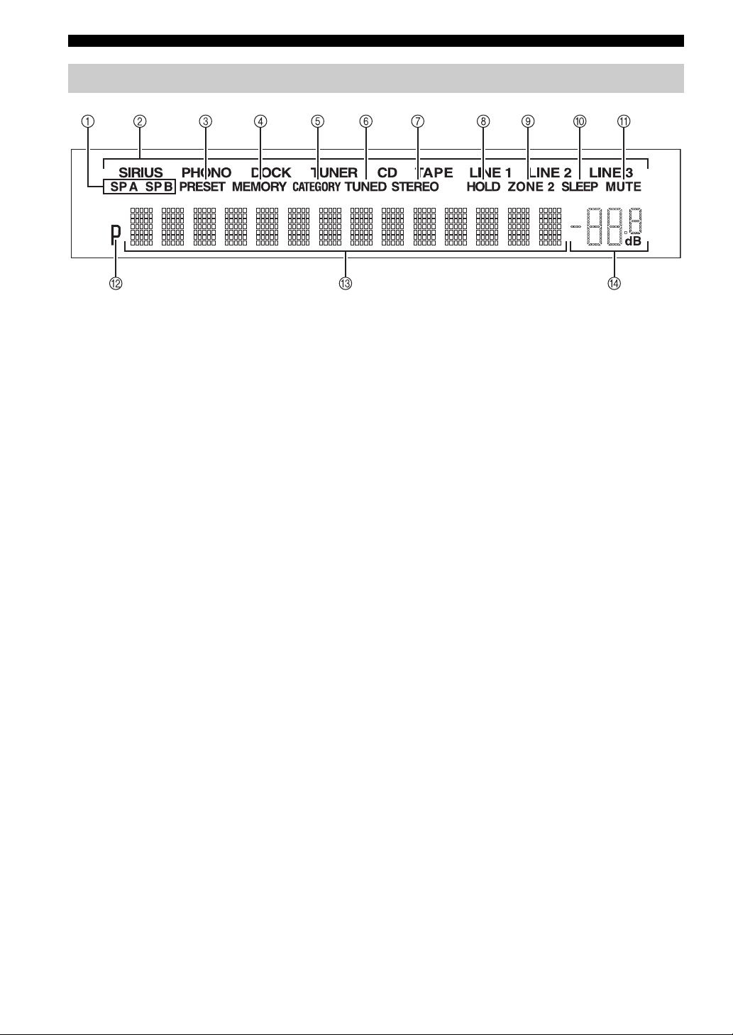
Front panel display
1 SP (SPEAKERS) A/B indicators
Light up according to the set of speakers selected.
Both indicators light up when both sets of speakers are
selected.
2 Input source indicators
Light up brightly to indicate the input source that is
currently selected.
3 PRESET indicator
Lights up when you recall a preset radio station or SIRIUS
channel. Blinks while the automatic station preset feature
is scanning for FM stations to register as presets.
4 MEMORY indicator
Lights up or blinks when an FM/AM station or SIRIUS
channel is being stored as a preset.
5 CATEGORY indicator
Lights up when searching for a SIRIUS channel by
category.
6 TUNED indicator
Lights up when this unit is tuned in to an FM or AM
station.
7 STEREO indicator
Lights up when this unit is receiving a strong signal for an
FM stereo broadcast.
8 HOLD indicator
Blinks when the hold function is used to display the artist
name, song title, etc. while listening to a SIRIUS channel.
B P indicator
Lights up when a preset number is selected. Blinks while
you are registering a preset radio station or SIRIUS
channel.
C Multi-information display
Shows information when adjusting or changing settings.
D Volume indicator
Displays the current volume level.
9 ZONE 2 indicator
Lights up when Zone 2 is turned on.
0 SLEEP indicator
Lights up when the sleep timer is turned on.
A MUTE indicator
Blinks while the MUTE function is turned on.
6 En
Page 11
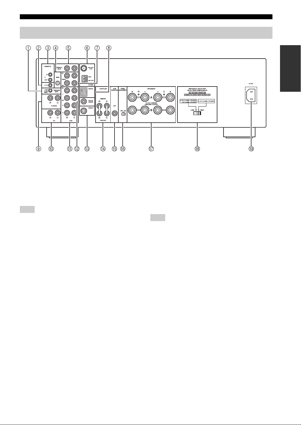
Rear panel
(R-S700)
CONTROLS AND FUNCTIONS
CONTROLS AND FUNCTIONS
INTRODUCTION
1 TRIGGER OUT jack (R-S700 only)
When this unit is turned on or when a certain input source
is selected, this unit can send a 12 V/100 mA direct
electric current via the TRIGGER OUT jack that can be
used to control an external component. The current is sent
according to the “Trigger out” setting in the Option menu
(see page 40).
Note
Do not connect a component that requires more than 100 mA of
electric current, otherwise the component may not perform
consistently or properly due to insufficient power.
2 REMOTE 2 IN jack (R-S700 only)
Used to receive remote control signals (see page 45).
3 REMOTE 1 IN/OUT jacks
Used to send and receive remote control signals (see page
45).
4 GND terminal
Used to connect a turntable (see page 12).
5 ZONE 2 OUT jacks
Used to connect a Zone 2 component (see page 45).
6 Antenna terminals
Used to connect FM and AM antennas (see page 14).
7 TAPE jacks
Used to connect a tape deck (see page 12).
8 DOCK jack
Used to connect an optional Yamaha Universal Dock for
iPod (such as the YDS-12), Wireless System for iPod
(YID-W10), or Bluetooth Wireless Audio Receiver
(YBA-10) (see page 35).
9 PHONO jacks
Used to connect a turntable (see page 12).
0 CD jacks
Used to connect a CD player (see page 12).
A LINE 1-3 jacks
Used to connect audio components (see page 12).
B iPod VIDEO output jack (R-S700 only)
Used to send iPhone/iPod video content to a video
monitor, such as a TV (see page 35).
Note
Video content output is possible only when an iPhone/iPod is
connected this unit using a Universal Dock for iPod (such as the
YDS-12).
C SIRIUS jack
Used to connect SiriusConnect tuner (sold separately) (see
page 27).
D COUPLER jacks (R-S700 only)
Used to connect an external unit (see page 15).
E SUBWOOFER OUT jack
Used to connect a subwoofer with built-in amplifier (see
page 12).
F POWER MANAGEMENT switch
Used to enable or disable the automatic power down
function. When this function is enabled, this unit’s Main
zone and Zone 2 automatically enters standby mode if this
unit is not operated for a certain amount of time (3 settings
are available; see page 43).
G SPEAKERS terminals
Used to connect speakers (see page 12).
H IMPEDANCE SELECTOR switch
Used to select the impedance setting (see page 13).
I AC IN (R-S700 only)
Used to plug in the supplied power cable (see page 15).
7 En
Page 12
CONTROLS AND FUNCTIONS
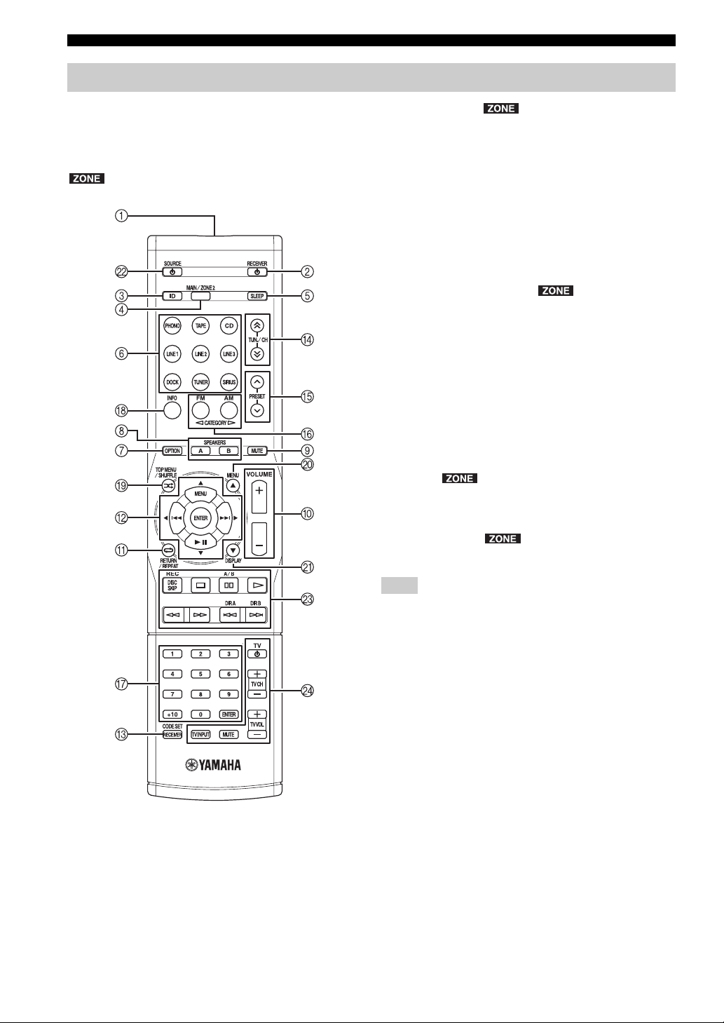
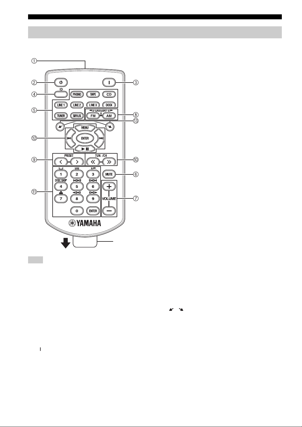
Remote control
This section describes the function of each button on the
remote control used to control this unit or other
components made by Yamaha or other manufacturers.
y
indicates buttons that can also be used to control Zone 2.
For more information about Zone 2, see pages 45 and 46.
2 RECEIVER A
Turns this unit on, or sets it to standby mode.
3 ID
Changes the remote control ID (see page 44).
4 MAIN/ZONE 2
Switches the zone to be operated by the remote control
between the Main Zone and Zone 2 (see page 46).
5 SLEEP
Sets the sleep timer (see page 19).
6 Input selector buttons
Selects the input source and changes the control area (see
page 47).
7 OPTION
Turns the OPTION menu on and off (see page 40).
8 SPEAKERS A/B
Turns on and off the set of speakers connected to the
SPEAKERS A and/or SPEAKERS B terminals on the rear
panel of this unit when the corresponding button is
pressed.
9 MUTE
Mutes the sound output. Press again to restore the sound
output to the previous volume level.
■ Common controls
The following buttons can be used no matter which input
source is selected.
1 Infrared signal transmitter
Sends infrared signals.
0 VOLUME +/– ( R-S700 only)
Increases or decreases the sound output level.
Note
This does not affect the output level of the REC jacks.
A RETURN
Returns to the previous menu or ends the menu display
when using the Option menu (see page 40).
B B / C / D / E / ENTER
Selects and confirms items in the Option menu (see page
40).
C CODE SET/RECEIVER
Used to program the remote control so that it can control
your other external components (see page 49).
After using the remote control to control one of your
components, this button is used to switch the remote
control to receiver mode so that remote control commands
will be sent to this unit (see page 48).
8 En
Page 13

CONTROLS AND FUNCTIONS
■ SIRIUS and FM/AM controls
The following buttons can be used when SIRIUS or
TUNER is selected as the input source.
D TUN./CH H / I
Selects the tuning frequency when TUNER is selected as
the input source (see page 20).
Searches for a SIRIUS channel when SIRIUS is selected
as the input source (see page 29).
E PRESET F / G
Selects a preset FM/AM station when TUNER is selected
as the input source (see page 24).
Select a preset SIRIUS channel when SIRIUS is selected
as the input source (see page 31).
F FM/CATEGORY l, AM/CATEGORY h
Sets the FM/AM tuner band to FM or AM when TUNER
is selected as the input source (see page 20).
Selects a channel category when SIRIUS is selected as the
input source (see page 29).
G Numeric buttons, ENTER
Specifies the frequency or the preset number of the FM/
AM station when TUNER is selected as the input source
(see page 21).
Specifies the channel number or preset number of the
SIRIUS channel when SIRIUS is selected as the input
source (see page 30).
H INFO
Changes the SIRIUS Satellite Radio information
displayed on the front panel display when SIRIUS is
selected as the input source (see page 34).
■ External component controls
The following buttons can be used to control external
audio/video components when CD, TAPE, PHONO,
LINE1, LINE2, or LINE3 is selected as the input source.
For more information, see page 47.
A RETURN
B B / C / D / E / ENTER
G Numeric buttons, ENTER
I TOP MENU
J MENU
K DISPLAY
L SOURCE A
M External component control buttons
N TV control buttons
INTRODUCTION
■ iPod controls
The following buttons can be used when DOCK is
selected as the input source for listening to an iPhone/
iPod. For more information, see page 35.
A REPEAT
B MENU/ Ee / b / a / ENTER
H INFO
I SHUFFLE
J B
K C
9 En
Page 14
CONTROLS AND FUNCTIONS
Zone 2 remote control (R-S700 only)
This section describes the function of each button on the
Zone 2 remote control, which is used to control Zone 2.
Insulation sheet
Note
The Zone 2 remote control comes with a battery already installed.
Before using the Zone 2 remote control for the very first time,
pull out the insulation sheet, as shown.
■ Common controls for Zone 2
The following buttons can be used no matter which input
source is selected for Zone 2.
1 Infrared signal transmitter
Sends infrared signals.
2 A (Zone 2 standby)
Sets Zone 2 to standby mode.
6 MUTE
Mutes the sound output to Zone 2. Press again to restore
the sound output to the previous volume level.
7 VOLUME +/–
Increases or decreases the sound output level of Zone 2.
■ SIRIUS and FM/AM controls
The following buttons can be used when SIRIUS or
TUNER is selected as the input source for Zone 2.
8 FM/CATEGORY l, AM/CATEGORY h
Sets the FM/AM tuner band to FM or AM when TUNER
is selected as the input source (see page 20).
Selects a channel category when SIRIUS is selected as the
input source (see page 29).
9 PRESET j / i
Selects a preset FM/AM station when TUNER is selected
as the input source (see page 24).
Selects a preset SIRIUS channel when SIRIUS is selected
as the input source (see page 31).
0 TUN./CH jj / ii
Selects the tuning frequency when TUNER is selected as
the input source (see page 20).
Searches for a SIRIUS channel when SIRIUS is selected
as the input source (see page 29).
A Numeric buttons, ENTER
Specifies the frequency or the preset number of the FM/
AM station when TUNER is selected as the input source
(see page 21).
Specifies the channel number or preset number of the
SIRIUS channel when SIRIUS is selected as the input
source (see page 30).
■ iPod controls
The following buttons can be used when DOCK is
selected as the input source for Zone 2, for listening to an
iPhone/iPod. For more information, see page 35.
B MENU/ Ee / b / a / ENTER
C /
3 (Zone 2 on)
Turns on Zone 2.
4 ID
Changes the Zone 2 remote control ID (see page 44).
5 Zone 2 input selector buttons
Selects the desired input source for Zone 2.
10 En
Page 15
CONTROLS AND FUNCTIONS
■ Yamaha CD player controls
The following buttons can be used to control a Yamaha
CD player when CD is selected as the input source for
Zone 2.
A Yamaha CD player control buttons
• s Stops playback
• e Pauses playback
• p Starts playback
• DISC SKIP Skips to the next disc in a CD changer
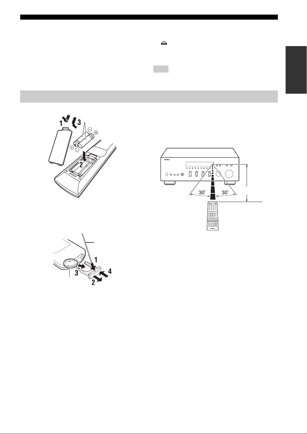
Using the remote controls
■ Installing batteries
AAA, R03, UM-4 batteries
• b Skips backward
• a Skips forward
• Ejects the disc
• w Rewinds playback
• f Fast-forwards playback
Note
Not all Yamaha CD players can be controlled by the Zone 2
remote control.
■ Operation range
The remote controls transmit a directional infrared beam.
Be sure to aim the remote controls directly at the remote
control sensor on the front panel of this unit or on the
infrared signal receiver in Zone 2 during operation.
Approximately
6 m (20 ft)
INTRODUCTION
■ Replacing the battery in the Zone 2
remote control
Change the battery when the operation range of the Zone 2
remote control decreases.
Straight pin
CR2025 battery
Remote control or Zone 2
remote control
11 En
Page 16
CONNECTIONS
CONNECTIONS
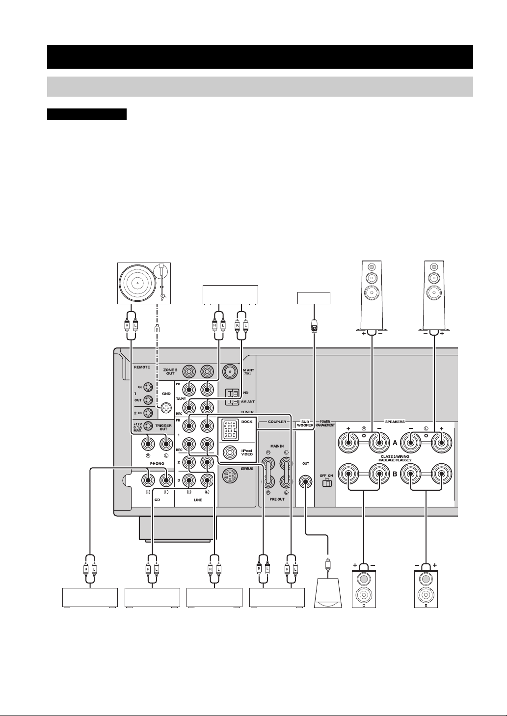
Connecting speakers and source components
CAUTION
• Do not connect this unit or other components to the main power until all connections between components are
complete.
• All connections must be correct: L (left) to L, R (right) to R, “+” to “+” and “–” to “–”. If the connections are faulty,
no sound will be heard from the speakers, and if the polarity of the speaker connections is incorrect, the sound will be
unnatural and lack bass. Refer to the owner’s manual for each of your components.
• Use RCA cables for audio components (except for speaker connections and DOCK jack connections).
• The IMPEDANCE SELECTOR must be set to the appropriate position before connecting speakers. See page 13 for
details.
• Do not let bare speaker wires touch each other or any metal part of this unit. This could damage this unit and/or the
speakers.
Audio
out
Turntable
GND
Audio
out
Tape deck
For information about
other components that
can be connected to
this unit, see page 35.
Audio
in
Speakers A
Audio
out
CD player
Audio
out
VCR, etc.
Audio
out
DVD player,
etc.
Audio
in
CD recorder,
etc.
Audio
out
Subwoofer
Speakers B
y
• The PHONO jacks are designed for connecting a turntable with an MM cartridge.
• Connect your turntable to the GND terminal to reduce noise in the signal. However, for some turntables, you may hear less noise
without the GND connection.
12 En
Page 17
CONNECTIONS
■ IMPEDANCE SELECTOR switch
CAUTION
Do not change the IMPEDANCE SELECTOR switch
while the power of this unit is turned on, as doing so may
damage the unit.
If the unit fails to turn on, the IMPEDANCE SELECTOR
switch may not be fully slid to either position. If this is the
case, remove the power cable and slide the switch all the
way to either position.
Select the switch position (LOW or HIGH) according to
the impedance of the speakers in your system.
Switch
position
HIGH
LOW
• If you use one set (A or B), the impedance of
each speaker must be 6
or 8
• If you make bi-wire connections, the
impedance of each speaker must be 6
higher (R-S700) or 8
See page 13 for Bi-wire connection.
• If you use one set (A or B), the impedance of
each speaker must be 4
• If you use two sets (A and B) simultaneously,
the impedance of each speaker must be 8
higher.
• If you make bi-wire connections, the
impedance of each speaker must be 4
higher. See page 13 for Bi-wire connection.
Impedance level
Ω or higher (R-S700)
Ω or higher (R-S500).
Ω or
Ω or higher (R-S500).
Ω or higher.
Ω or
Ω or
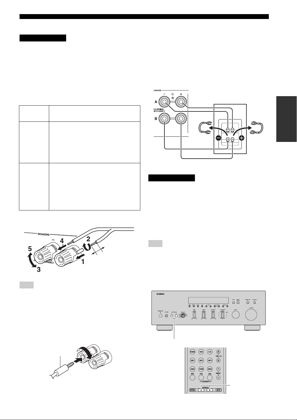
■ Connecting speaker cables
Remove
approximately
10 mm (3/8 in)
of insulation
from the end of
each speaker
cable.
Note
When inserting speaker cables into the speaker terminals, insert
only the bare speaker wire. If insulated cable is inserted, the
connection may be poor and sound may not be heard.
■ Bi-wire connection
Bi-wire connection separates the woofer from the
combined midrange and tweeter section. A bi-wire
compatible speaker has four binding post terminals. These
two sets of terminals allow the speaker to be split into two
independent sections. With these connections, the mid and
high frequency drivers are connected to one set of
terminals and the low frequency driver to another set of
terminals.
This unit
Speaker
Connect the other speaker to the other set of terminals in
the same way.
CAUTION
When making bi-wire connections, set the IMPEDANCE
SELECTOR switch to HIGH or LOW depending on the
impedance of your speakers:
6 Ω or higher: HIGH (R-S700)
8 Ω or higher: HIGH (R-S500)
4 Ω or higher: LOW
See page 13 for more information about the
IMPEDANCE SELECTOR switch.
Note
When making bi-wire connections, remove the shorting bridges
or cables on the speaker.
y
To use the bi-wire connections, press SPEAKERS A and
SPEAKERS B on the front panel or on the remote control so that
both SP A and B light up on the front panel display.
PREPARATION
■ Connecting via banana plug
Tighten the knob and then insert the banana plug into the
end of the corresponding terminal.
Banana plug
SPEAKERS A/B
SPEAKERS A/B
13 En
Page 18
CONNECTIONS
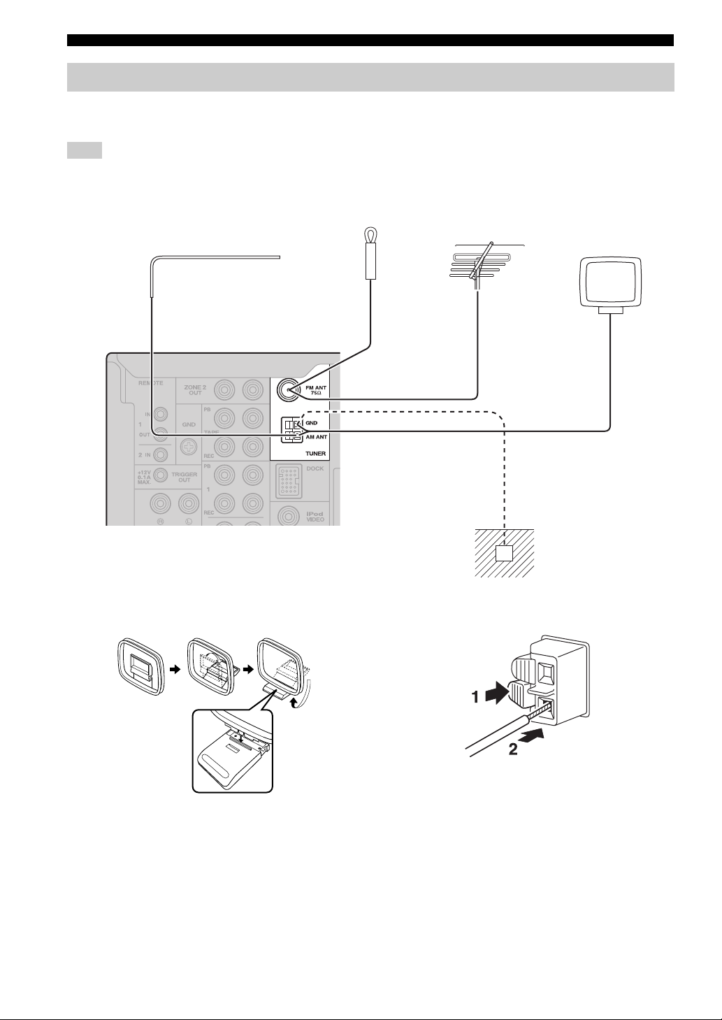
Connecting the FM and AM antennas
Indoor antennas for receiving FM and AM broadcasts are included with this unit. In general, these antennas should
provide sufficient signal strength. Connect each antenna correctly to the designated terminals.
Note
If you experience poor reception quality, install an outdoor antenna. Consult the nearest authorized Yamaha dealer or service center
about outdoor antennas.
Indoor FM antenna
(included)
Outdoor FM antenna
Outdoor AM antenna
Use 5 to 10 m of vinylcovered wire extended
outdoors from a window.
AM loop antenna
(included)
• The AM loop antenna
should always be connected,
even if an outdoor AM
antenna is connected to this
unit.
• The AM loop antenna
should be placed away from
this unit.
Ground (GND terminal)
For maximum safety and minimum interference, connect
the antenna GND terminal to a good earth ground. A
good earth ground is a metal stake driven into moist earth.
■ Assembling the supplied AM loop
antenna
■ Connecting the wire of the AM loop
antenna
14 En
Page 19
CONNECTIONS
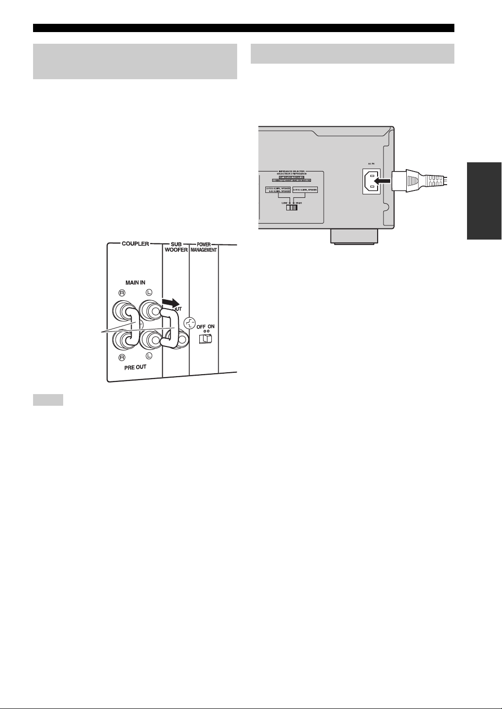
Using COUPLER jacks (R-S700 only)
Removing the jumper pins from the PRE OUT/MAIN IN
jacks enables this unit to operate separately as a control
amplifier or a power amplifier. These jacks are used to
connect a signal-processing system such as a graphic
equalizer or a surround-sound processor to this unit. If an
external unit is connected to these jacks, the VOLUME
control of this unit can be used to adjust the overall sound
output level.
To connect an external unit, first remove the jumper pins
from the PRE OUT/MAIN IN jacks and then connect the
input jacks of that external unit to the PRE OUT jacks or
its output jacks to the MAIN IN jacks. For details, refer to
the owner’s manual included with the external unit to be
connected.
Jumper pins
Connecting power cable
Plug the power cable into the AC IN on the rear panel of
this unit (R-S700 only).
Plug the power cable into the AC wall outlet after all other
connections are complete.
PREPARATION
Power cable
(R-S700 only)
Notes
• If you do not use the COUPLER jacks, never remove the
jumper pins from these jacks. If removed, no sound will be
output from this unit.
• Before installing or removing the jumper pins, be sure to
disconnect the power cable of the unit. Leaving the power cable
connected could cause noise to be emitted from the speakers or
damage the unit.
• When you use this unit as a power amplifier, connect the output
jacks of the external control amplifier, etc. to the MAIN IN
jacks of this unit. In this case, the controls of this unit will not
function except the PHONES jack and the SPEAKERS A/B
buttons. Use the controls on the external control amplifier to
make volume adjustments, etc.
15 En
Page 20
PLAYING AND RECORDING
PLAYING AND RECORDING
CAUTION
Extreme caution should be exercised when you play back CDs encoded in DTS.
If you play back a CD encoded in DTS on a CD player that does not support DTS, only noise will be heard, and this noise
may damage your speakers. Check whether your CD player supports CDs encoded in DTS. Also, check the sound output
level of your CD player before you play back a CD encoded in DTS.
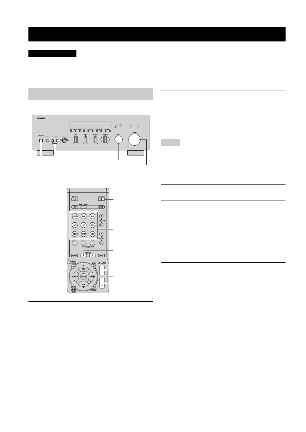
Playing a source
SPEAKERS A/B INPUT selector
MAIN ZONE A
VOLUME
RECEIVER A
Input selector
buttons
SPEAKERS A/B
3 Press SPEAKERS A and/or SPEAKERS B on
the front panel or on the remote control to
select speakers A and/or speakers B.
When speaker set A or speaker set B are turned on,
SP A or SP B is displayed on the front panel display
accordingly (see page 6).
Notes
• When one set of speakers is connected using bi-wire
connections, or when using two sets of speakers simultaneously
(A and B), make sure SP A and SP B are displayed on the front
panel display.
• When listening with headphones, turn off the speakers.
4 Play the source.
5 Rotate the VOLUME control on the front
panel (or press VOLUME +/– on the remote
control) to adjust the sound output level.
y
You can adjust the tonal quality by using the BASS, TREBLE,
BALANCE and LOUDNESS controls, the CD DIRECT AMP
switch (R-S700 only), or the PURE DIRECT switch on the front
panel (see page 17).
VOLUME +/–
1 Press MAIN ZONE A on the front panel (or
RECEIVER A on the remote control) to turn
on this unit.
2 Rotate the INPUT selector on the front panel
(or press one of the input selector buttons on
the remote control) to select the input source
you want to listen to.
16 En
6 Press MAIN ZONE A on the front panel again
(or RECEIVER A on the remote control) to
finish using this unit and set it to standby
mode.
Page 21
Adjusting the tonal quality
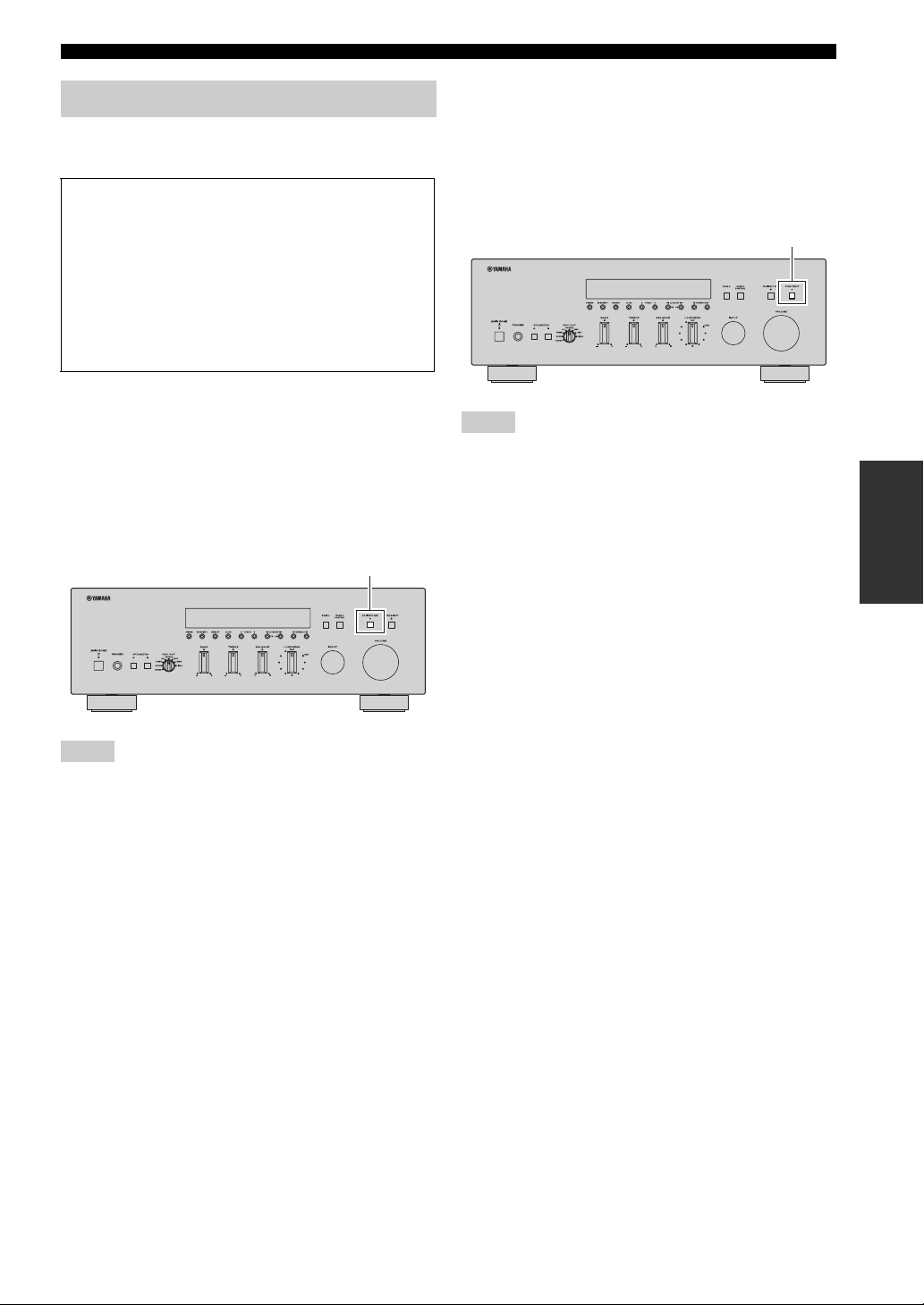
■ Using the CD DIRECT AMP switch
(R-S700 only)
CD Direct Amp feature
Generates a normal phase and reverse phase signal for
both the left and right channels from the input signal
and uses the four electronic volumes to send a
balanced signal to the amplifying circuit. This feature
provides clearer sound as a result of:
• improved signal-to-noise ratio
• external noise canceling
• reduced distortion
Routes input signals from your CD player directly to the
specially built-in amplifier for the CD player. As a result,
the input signals bypass the INPUT selector and the
BASS, TREBLE, BALANCE and LOUDNESS controls
and then sent to the power amplifier, thus eliminating any
alterations to the CD signals and creating the purest
possible sound. The CD DIRECT AMP indicator lights up
and the front panel display turns off after a few seconds.
CD DIRECT AMP switch
PLAYING AND RECORDING
■ Using the PURE DIRECT switch
Routes input signals from your audio sources so that the
input signals bypass the BASS, TREBLE, BALANCE and
LOUDNESS controls, thus eliminating any alterations to
the audio signals and creating the purest possible sound.
The PURE DIRECT indicator lights up and the front panel
display turns off after a few seconds.
PURE DIRECT switch
Notes
• Zone 2 cannot be used while the PURE DIRECT feature is
turned on.
• The BASS, TREBLE, BALANCE, and LOUDNESS controls
do not function while the PURE DIRECT feature is turned on.
• This setting is retained even if you turn off this unit.
OPERATION
BASIC
Notes
• If both the CD DIRECT AMP and the PURE DIRECT switches
are turned on, only the CD DIRECT AMP switch will function.
• Zone 2 cannot be used while the CD DIRECT AMP feature is
turned on.
• The INPUT selector and the BASS, TREBLE, BALANCE, and
LOUDNESS controls do not function while the CD DIRECT
AMP feature is turned on.
• A CD player must be connected to the CD jacks in order to use
the CD DIRECT AMP feature.
• This setting is retained even if you turn off this unit.
17 En
Page 22
PLAYING AND RECORDING
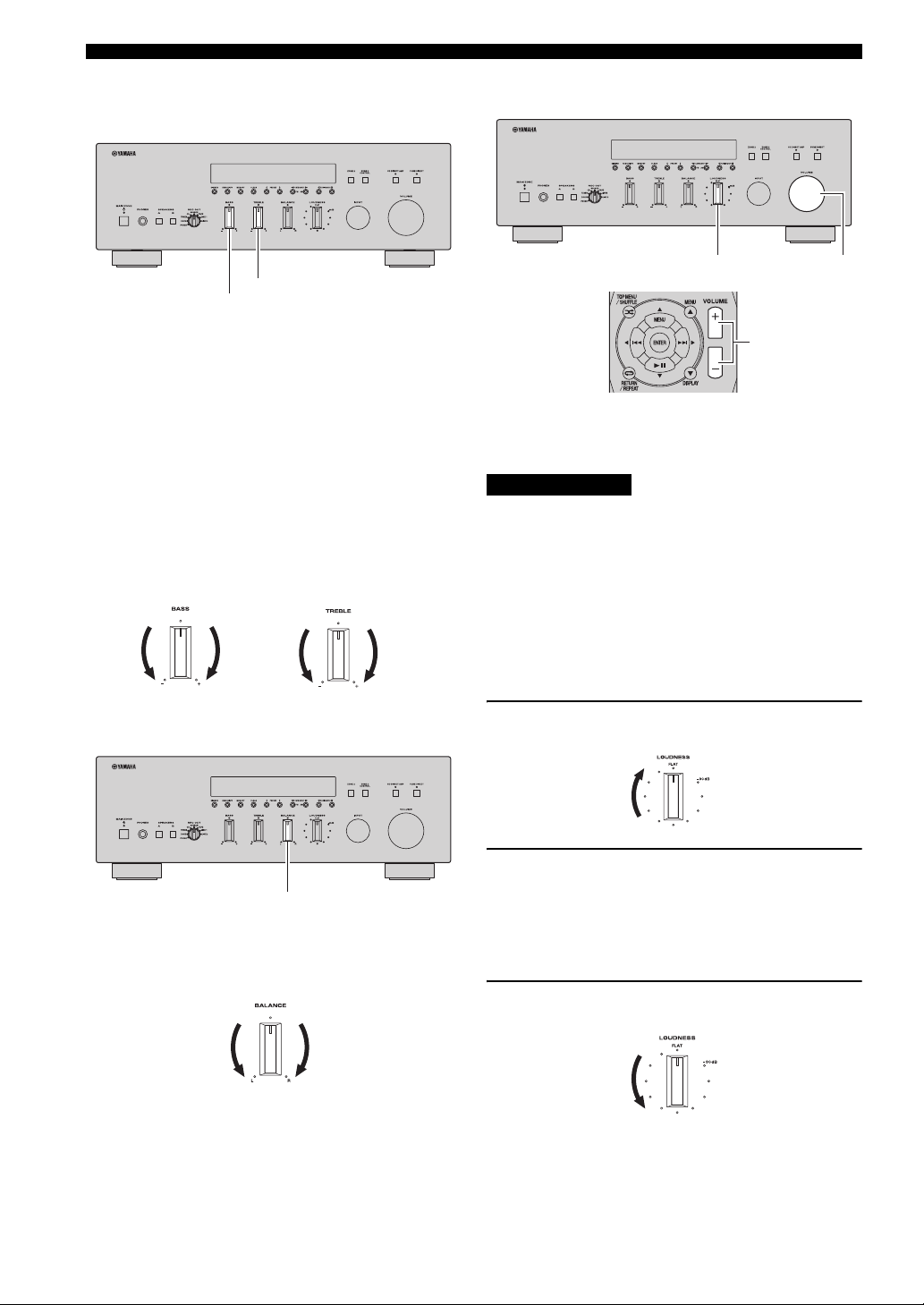
■ Adjusting the BASS and TREBLE
controls
TREBLE
BASS
The BASS and TREBLE controls adjust high and low
frequency response.
The center position produces a flat response.
BASS
When you feel there is not enough bass (low frequency
sound), rotate clockwise to boost. When you feel there is
too much bass, rotate counterclockwise to suppress.
Control range: –10 dB to +10 dB (20 Hz)
TREBLE
When you feel there is not enough treble (high frequency
sound), rotate clockwise to boost. When you feel there is
too much treble, rotate counterclockwise to suppress.
Control range: –10 dB to +10 dB (20 kHz)
■ Adjusting the LOUDNESS control
LOUDNESS VOLUME
VOLUME +/–
Retain a full tonal range at any volume level, thus
compensating for the human ears’ loss of sensitivity to
high and low-frequency ranges at low volume.
CAUTION
If the CD DIRECT AMP switch (R-S700 only) or the
PURE DIRECT switch is turned on with the LOUDNESS
control set at a certain level, the input signals bypass the
LOUDNESS control, resulting in a sudden increase in the
sound output level. To prevent your ears or the speakers
from being damaged, be sure to press the CD DIRECT
AMP switch (R-S700 only) or the PURE DIRECT switch
after lowering the sound output level or after checking that
the LOUDNESS control is properly set.
■ Adjusting the BALANCE control
BALANCE
The BALANCE control adjusts the sound output balance
of the left and right speakers to compensate for sound
imbalance caused by speaker locations or listening room
conditions.
1 Set the LOUDNESS control to the FLAT
position.
2 Rotate the VOLUME control on the front
panel (or press VOLUME +/– on the remote
control) to set the sound output level to the
loudest listening level that you would listen
to.
3 Rotate the LOUDNESS control until the
desired volume is obtained.
y
After setting the LOUDNESS control, enjoy listening to music at
your preferred volume level. If the effect of the LOUDNESS
control setting is too strong or weak, readjust the LOUDNESS
control.
18 En
Page 23

PLAYING AND RECORDING
Recording a source
Notes
• Audio signals are not output to the TAPE REC or LINE 1 REC
output jacks when TAPE or LINE 1 is selected with the REC
OUT selector.
Audio signals are output to both the TAPE REC and the LINE 1
REC output jacks if when PHONO, DOCK, TUNER, CD,
SOURCE or LINE 2 is selected with the REC OUT selector.
• This unit must be turned on in order to record.
• The VOLUME, BASS, TREBLE, BALANCE and
LOUDNESS controls and the CD DIRECT AMP switch (RS700 only) and the PURE DIRECT switch have no effect on the
source being recorded.
• Check the copyright laws in your country before recording from
records, CDs, radio, etc. Recording copyright-protected
material may infringe on copyright laws.
INPUT selectorREC OUT selector
Using the sleep timer
Use this feature to automatically set this unit to standby
mode after a certain amount of time. The sleep timer is
useful when you are going to sleep while this unit is
playing or recording a source.
MAIN ZONE A
RECEIVER A
SLEEP
OPERATION
BASIC
1 Rotate the REC OUT selector on the front
panel to select the source you want to
record.
When SOURCE is selected, the current input source
is output.
Note
SIRIUS Satellite Radio broadcasts cannot be recorded.
2 Play the source and begin recording using
the recording device connected to the REC
jacks (TAPE and/or LINE 1) on the rear panel.
See page 12.
Notes
• The sleep timer can only be set with the remote control.
• The sleep timer automatically turns off Zone 2. However, Zone
2 components are not turned off.
1 Press SLEEP repeatedly to set the amount of
time before this unit is set to standby mode.
Each time you press SLEEP, the front panel display
changes as shown below.
The SLEEP indicator blinks while setting the amount
of time for the sleep timer.
If the sleep timer is set, the SLEEP indicator on the
front panel display lights up.
y
• To disable the sleep timer, select “Sleep Off”.
• The sleep timer setting can also be canceled by pressing
RECEIVER
the front panel) to set this unit to standby mode.
A on the remote control (or MAIN ZONE A on
19 En
Page 24

FM/AM TUNING
FM/AM TUNING
There are 2 tuning methods; automatic and manual. Select either method according to your preference and the strength of
station signals.
Automatic tuning
Automatic tuning is effective when station signals are
strong and there is no interference.
INPUT selector
TUNING/CH jj / ii
FM, AM
TUN./CH H / I
TUNER
FM, AM
3 Press and hold TUNING/CH jj / ii on the
front panel (or TUN./CH H / I on the remote
control) for more than 1 second to begin
automatic tuning.
Press ii (or H) to tune in to a higher frequency.
Press jj (or I) to tune in to a lower frequency.
Notes
• When you tune in to a station, the frequency of the station is
displayed on the front panel display.
• If the tuning search does not stop at the desired station because
the station signals are weak, try using the manual tuning
method.
■ Auto Mute feature
When listening to an FM radio station, the output will
automatically be muted when the radio signal is weak if
the station was tuned in to by:
• using the automatic tuning feature
• recalling a preset that was registered using the
automatic preset registration feature
If you want to listen to a station that has a weak signal,
tune in to the station manually.
1 Rotate the INPUT selector on the front panel
(or press TUNER on the remote control) to
select TUNER as the input source.
2 Press FM or AM on the front panel (or FM or
AM on the remote control) to select the
reception band (FM or AM).
FM or AM is displayed on the front panel display.
20 En
Page 25

FM/AM TUNING
Manual tuning
Manual tuning is effective when station signals are weak.
INPUT selector
TUNING/CH jj / ii
FM, AM
TUN./CH H / I
TUNER
FM, AM
Numeric
buttons
4 To tune in by direct frequency tuning, press
the numeric buttons on the remote control to
enter the frequency of the station.
Enter only integers. For example, if you want to set
the frequency to 88.9 MHz, enter “889”.
Notes
• When you press the numeric buttons on the remote control
during preset tuning, a preset number is selected. Set the tuning
mode to frequency tuning mode using TUNING/CH jj / ii on
the front panel (or TUN./CH H / I on the remote control)
before pressing the numeric buttons.
• “WRONG STATION!” is displayed on the front panel display if
you enter a frequency that is out of receivable range. Make sure
that the entered frequency is correct.
BASIC OPERATION
■ Improving FM reception
If the signal from the station is weak and the sound quality
is not good, set the FM band reception mode to monaural
mode to improve reception.
OPERATION
BASIC
1 Rotate the INPUT selector on the front panel
(or press TUNER on the remote control) to
select TUNER as the input source.
2 Press FM or AM on the front panel (or FM or
AM on the remote control) to select the
reception band (FM or AM).
FM or AM is displayed on the front panel display.
3 Press TUNING/CH jj / ii on the front panel
(or TUN./CH H / I on the remote control) to
manually tune in to the desired station.
Note
When you tune in to a station, the frequency of the received
station is shown in the front panel display.
FM MODE/INFO
1 Press FM MODE/INFO on the front panel
repeatedly to select “STEREO” (automatic
stereo mode) or “MONO” (monaural mode)
when this unit is tuned in to an FM radio
station.
• When MONO is selected, FM broadcasts will be
heard in monaural sound.
• When STEREO is selected and an FM station with
a stereo broadcast is tuned in, the broadcast will be
heard in stereo.
Note
The STEREO indicator on the front panel lights up while
listening to a station in stereo.
y
The FM band reception mode (monaural or stereo) can also be
changed by selecting FM Mode in the Option menu (see page 40).
21 En
Page 26

FM/AM TUNING
Automatic station preset (FM stations only)
You can use the automatic station preset function to
automatically register FM stations as presets. This
function enables this unit to automatically tune in to FM
stations that have a strong signal and store up to 40 of
those stations in order. You can then easily recall any
preset station by selecting its preset number.
Notes
• If a station is registered to a preset number that already has a
station registered to it, the previously registered station is
overwritten.
• If the station you want to store is weak in signal strength, try
using the manual preset tuning method.
y
FM stations registered as presets using the automatic preset
registration feature will be heard in stereo.
FM
PRESET j / i
INPUT selector
TUNER
PRESET F / G
3 Press OPTION on the remote control.
The Option menu for TUNER is displayed (see page
40).
4 Press B / C on the remote control to select
“Auto Preset”, and then press ENTER.
This unit starts scanning the FM band about 5
seconds later from the lowest frequency upwards.
y
• Before scanning begins, you can specify the first preset number
to be used by pressing PRESET j / i on the front panel (or
PRESET F/G or B/C on the remote control).
• To cancel scanning, press FM or AM on the front panel (or FM
or AM or RETURN on the remote control).
Preset number Frequency
When presets are registered, information is displayed
on the front panel display as shown in the illustration
above.
When scanning is complete, “FINISH” is displayed
and then the display returns to the Option menu.
To return the display to the original state, press
OPTION or RETURN on the remote control.
OPTION
B / C
ENTER
RETURN
FM
1 Rotate the INPUT selector on the front panel
(or press TUNER on the remote control) to
select TUNER as the input sourse.
2 Press FM on the front panel (or FM on the
remote control) to select FM as the reception
band.
FM is displayed on the front panel display.
22 En
Page 27

FM/AM TUNING
Manual station preset
You can manually register up to 40 FM/AM stations
(40 total). You can then easily recall any preset station by
selecting its preset number.
PRESET j / i
MEMORY
PRESET F / G
3 Press PRESET j / i on the front panel (or
PRESET F / G on the remote control) to
select the preset number to which the station
will be registered.
When you select a preset number to which no station
is registered, “EMPTY” is displayed. When you
select a preset number to which a station has already
been registered, the frequency of the station is
displayed.
Preset number
y
You can also select a preset number using the numeric buttons on
the remote control.
4 Press MEMORY on the front panel.
When registration is complete, the display returns to
the original state.
y
To cancel registration, RETURN on the remote control or do not
perform any operations for about 30 seconds.
OPERATION
BASIC
RETURN
Numeric
buttons
1 Tune in to the desired FM/AM station.
See pages 20 and 21 for tuning instructions.
2 Press MEMORY on the front panel.
“MANUAL PRESET” is displayed briefly on the
front panel display, and then the preset number to
which the station will be registered is displayed.
y
By holding down MEMORY on the front panel for more than
2 seconds, you can skip the following steps and automatically
register the selected station to an empty preset number (i.e., the
preset number following the last preset number used).
23 En
Page 28

FM/AM TUNING
Recalling a preset station
You can recall preset stations that were registered using
automatic station preset or manual station preset.
PRESET j / i
PRESET F / G
1 Press PRESET j / i on the front panel (or
PRESET F / G on the remote control) to
select a preset number.
y
• Preset numbers to which no stations are registered are skipped.
• “NO PRESETS” is displayed if no stations are registered.
• You can directly select a preset number by pressing the numeric
buttons on the remote control while recalling a preset station.
“EMPTY” is displayed on the display if you enter a preset
number to which no station is registered. “WRONG NUM.” is
displayed if you enter an invalid number.
• When you press the numeric buttons on the remote control
during normal tuning, a frequency is entered. Set the tuning
mode to preset tuning mode using PRESET j / i on the front
panel (or PRESET F / G on the remote control) before
pressing numeric buttons.
Clearing a preset station
Follow the steps below to clear a preset station.
CLEAR
RETURN
1 Select the desired preset station number.
See “Recalling a preset station” on page 24.
2 Press CLEAR on the front panel.
The selected preset number flashes on the front panel
display.
y
To cancel clearing the preset station, press RETURN on the
remote control or leave this unit without any operations for about
30 seconds.
24 En
3 Press CLEAR on the front panel to confirm.
“PXX: CLEARED” (XX indicates the preset
number) is displayed on the front panel display, and
then the display returns to its original state.
Page 29

FM/AM TUNING
Clearing all preset stations
Follow the steps below to clear all preset stations.
INPUT selector
TUNER
OPTION
B / C / D / E
ENTER
RETURN
4 Press D / E on the remote control to select
“YES”, and then press ENTER.
y
To cancel without clearing the presets, select “NO”.
When all presets have been cleared, “PRESET
CLEARED” is displayed, and then the display returns
to the Option menu.
5 To exit the Option menu, press OPTION or
RETURN on the remote control.
OPERATION
BASIC
1 Rotate the INPUT selector on the front panel
(or press TUNER on the remote control) to
select TUNER as the input sourse.
2 Press OPTION on the remote control.
The Option menu for TUNER is displayed (see
page 40).
3 Press B / C on the remote control to select
“Clr All Preset”, and then press ENTER.
y
To cancel the operation and return to the Option menu, press
RETURN on the remote control.
25 En
Page 30

LISTENING TO SIRIUS SATELLITE RADIO™
LISTENING TO SIRIUS Satellite Radio™
Listening to Satellite Radio
To listen to Satellite Radio, you’ll need to connect a SIRIUS Satellite Radio tuner (sold separately) to your Sirius-Ready
receiver. SIRIUS Satellite Radio is available to residents of the US (except Alaska and Hawaii) and Canada.
Satellite Radio delivers a variety of commercial-free music from categories ranging from Pop, Rock, Country, R&B,
Dance, Jazz, Classical and many more plus coverage of all the top professional and college sports including play by play
games from select leagues and teams. Additional programming includes expert sports talk, uncensored entertainment,
comedy, family programming, local traffic and weather and news from your most trusted sources.
Once you’ve purchased a SIRIUS tuner you’ll need to activate it and subscribe to begin enjoying the service. Easy to
follow installation and setup instructions are provided with the SIRIUS tuner. There are a variety of programming
packages available, including the option of adding “The Best of XM” programming to the SIRIUS service. The “Best of
XM” service is not available to SIRIUS Canada subscribers at this time. Please check with SIRIUS Canada for any
updates using the numbers and web address below.
Family friendly packages are also available to restrict channels featuring content that may be inappropriate for children.
To subscribe to SIRIUS, U.S. and Canadian customers can call 1-888-539-SIRI (1-888-539-7474) or visit sirius.com
(US) or siriuscanada.ca (Canada).
SIRIUS Radio Legal
SIRIUS and all related marks and logos are trademarks of Sirius XM Radio Inc. and its subsidiaries. All other marks
and logos are the property of their respective owners. All rights reserved. SIRIUS subscription sold separately. Taxes
and a one-time activation fee may apply. SIRIUS tuner required (sold separately) to receive the SIRIUS service. All
programming and fees subject to change. It is prohibited to copy, decompile, disassemble, reverse engineer, hack,
manipulate or otherwise make available any technology or software incorporated in receivers compatible with the
SIRIUS Satellite Radio System. Service not available in Alaska or Hawaii.
26 En
Page 31

LISTENING TO SIRIUS Satellite Radio™
Connecting the SiriusConnect™ tuner
Connect the SiriusConnect tuner (sold separately) to the
SIRIUS jack on the rear panel of this unit. For details, see
the instruction manuals provided with the SiriusConnect
tuner.
SiriusConnect Tuner and the
antenna (sold separately)
To the AC wall outlet
y
• To ensure optimal reception of SIRIUS Satellite Radio signals,
the antenna of the SiriusConnect tuner must be placed at or near
a window with no obstacles in the path to the sky. You can
mount it indoors or outdoors. The orientation of the antenna for
the best reception differs depending on the area. Refer to the
instruction manuals provided with the SiriusConnect tuner for
information about antenna installation.
• Use the “Antenna” information on the front panel display (see
page 34) to check the antenna reception level and adjust the
orientation of the antenna.
• You need to connect the SiriusConnect tuner to the AC wall
outlet.
Activating SIRIUS Satellite Radio™ subscription
Before using the SIRIUS Satellite Radio feature, you need
to activate your SIRIUS Satellite Radio subscription. To
activate the subscription you need the Sirius ID which is
uniquely assigned to the SiriusConnect tuner. A Sirius ID
is 12-digit number which is indicated on the package of
the SiriusConnect tuner and on the label of the
SiriusConnect tuner. The Sirius ID is also displayed on the
front panel display when you tune in to the SIRIUS
Satellite Radio channel “0”.
■ Displaying the Sirius ID of your
SiriusConnect tuner
OPERATION
BASIC
INPUT selector
SIRIUS
Notes
• If “CHECK SR TUNER” or “ANTENNA ERROR” is
displayed on the front panel display, the SiriusConnect tuner or
antenna is not connected correctly. In such cases, check the
connection of the SiriusConnect tuner and the antenna.
• If “NOT SUPPORTED” is displayed on the front panel display,
this unit does not support the connected SiriusConnect tuner.
0
ENTER
27 En
Page 32

LISTENING TO SIRIUS Satellite Radio™
1 Rotate the INPUT selector on the front panel
(or press SIRIUS on the remote control) to
select SIRIUS as the input source.
2 Press 0 on the remote control and then
ENTER to display the Sirius ID of your
SiriusConnect tuner.
“000 Sirius ID” and “xxxxxxxxxxxx” is displayed
alternately on the front panel display.
(“xxxxxxxxxxxx” indicates the 12-digit Sirius ID of
your SiriusConnect tuner.)
Write the Sirius ID below.
ID:________________________________________
3 Contact SIRIUS Satellite Radio to activate
your subscription.
SIRIUS Satellite Radio online information
Contact for activation
URL: https://activate.siriusradio.com/
Phone: 1-888-539-SIRIUS (1-888-539-7474)
y
Status messages are displayed on the front panel display during
the activation. For details, see “SIRIUS Satellite Radio™” on
page 53. Once the activation is finished, “SUB UPDATED”
appears.
SIRIUS Satellite Radio™ operations
INPUT selectorFM MODE/INFO
SIRIUS
INFO
1 Rotate the INPUT selector on the front panel
(or press SIRIUS on the remote control) to
select SIRIUS as the input source.
The SIRIUS indicator lights up on the front panel
display and the SIRIUS Satellite Radio information
(such as channel number, channel name, category,
artist name, or song title) for the currently selected
channel is displayed on the front panel display.
28 En
Channel number Channel name
y
• When you select SIRIUS as the input source, this unit
automatically recalls the previously selected channel.
• You can change the SIRIUS Satellite Radio information that is
displayed by pressing FM MODE/INFO on the front panel (or
INFO on the remote control) (see page 34).
Notes
• If you have not activated your subscription yet, you can only
select “184” or “000”.
• If a status message or an error message is displayed on the front
panel display, see “SIRIUS Satellite Radio™” (see page 53).
Page 33

2 Search for a channel by using one of the
SIRIUS Satellite Radio search modes.
• All channel search mode
Selects a channel from a list of all channels (see
page 29).
• Category search mode
Selects a channel by category (see page 29).
• Direct number access mode
Selects a channel directly by channel number (see
page 30).
• Preset search mode
Selects a channel from the preset channels (see
page 31).
You can register channels as presets and then easily
recall any preset channel by selecting its preset
number.
y
• You can display SIRIUS Satellite Radio information on the
front panel display (see page 34).
• If you tune in to a channel that you do not subscribe to, “CALL
888-539-SIRIUS TO SUBSCRIBE” scrolls across the front
panel display, and then “CALL SIRIUS” is displayed.
• You can register SIRIUS Satellite Radio channels as presets
(see page 30).
LISTENING TO SIRIUS Satellite Radio™
y
• You can search for a channel quickly by holding down
TUNING/CH jj / ii on the front panel (or TUN./CH H / I on
the remote control).
• You can skip to channels in the previous or next category by
pressing CATEGORY l / h on the front panel (or
CATEGORY l / h on the remote control).
■ Category search mode
TUNING/CH jj / ii
CATEGORY l / h
OPERATION
BASIC
TUN./CH H / I
■ All channel search mode
TUNING/CH jj / ii
CATEGORY l / h
TUN./CH H / I
CATEGORY l / h
1 Press TUNING/CH jj / ii on the front panel
(or TUN./CH H / I on the remote control)
repeatedly to search for a channel from a list
of all channels.
CATEGORY l / h
1 Press CATEGORY l / h on the front panel
(or CATEGORY l / h on the remote control)
to select a channel category.
The CATEGORY indicator lights up in the front
panel display when selecting a category. When you
select a category, the first channel in the category is
selected.
Category name
y
You can search for a channel category quickly by pressing and
holding CATEGORY l / h on the front panel (or CATEGORY
l / h on the front panel).
Note
If no operations are performed for 10 seconds, the search mode
returns to the all channel search mode.
29 En
Page 34

LISTENING TO SIRIUS Satellite Radio™
2 While the CATEGORY indicator on the front
panel display is lit, press TUNING/CH jj / ii
on the front panel (or TUN./CH H / I on the
remote control) repeatedly to search for a
channel within the selected channel
category.
y
• You can search for a channel quickly by pressing and holding
TUNING/CH jj / ii on the front panel (or TUN./CH H / I on
the remote control).
• In the category search mode, you can only search for a channel
within the selected channel category.
Note
This unit skips the following channels in all channel search mode
or category search mode. This is not a malfunction.
• channels that are locked (see page 32)
• channels that are not currently in service
• channels that you do not subscribe to
■ Direct number access mode
Numeric
buttons,
ENTER
Registering and recalling SIRIUS Satellite Radio™ channels
Up to 40 SIRIUS Satellite Radio channels can be
registered as preset channels.
■ Registering preset channels
PRESET j / i
MEMORY
PRESET F / G
1 Press the numeric buttons on the remote
control to enter the desired three-digit
channel number.
For example, to enter the number 123, press the
numeric buttons “1,” “2” and then “3”.
y
• To entering a one-digit or two-digit channel number, enter the
number using the numeric buttons and then press ENTER on
the remote control to confirm your entry.
• This unit automatically accepts your entry if you do not press
ENTER on the remote control within a few seconds after
entering the number.
• If the selected channel is locked, “PIN:___” is displayed on the
front panel display. Enter the 4-digit Parental Lock code
number by using the numeric buttons or press ENTER on the
remote control to cancel (see page 32).
• If the selected channel is not available, an advisory message
may be displayed. For details, refer to “SIRIUS Satellite
Radio™” (see page 53).
• If this unit is in preset search mode, a preset number is selected
instead of a channel number when you press the numeric
buttons on the remote control. To switch to direct number
access mode, press TUNING/CH jj / ii on the front panel (or
TUN./CH H / I on the remote control).
RETURN
Numeric
buttons
1 Search for a channel to be registered.
For details on searching channels, refer to the
following pages.
• All channel search mode (see page 29)
• Category search mode (see page 29)
• Direct number access mode (see page 30)
30 En
Page 35

2 Press MEMORY on the front panel.
The indicator on the front panel display changes as
follows.
Currently registered channel number
(or “---” if empty)
LISTENING TO SIRIUS Satellite Radio™
■ Recalling a preset channel (Preset
Search mode)
You can recall preset channels by specifying their preset
numbers.
Preset number to which new
channel number is registered
Channel number to be
registered
y
• By holding down MEMORY on the front panel for more than
2 seconds, you can skip the following steps and automatically
register the selected channel to an empty preset number (i.e., the
preset number following the last preset number used).
• To cancel registration, press RETURN on the remote control or
do not perform any operations for about 30 seconds.
3 Press PRESET j / i on the front panel (or
PRESET F / G on the remote control) to
select preset number.
y
• You can also select a preset number using the numeric buttons
on the remote control.
• If you select a preset number that is being used (i.e., if the
currently registered channel number is displayed next to the
preset number), the current preset will be overwritten.
4 Press MEMORY on the front panel.
PRESET j / i
PRESET F / G
1 Press PRESET j / i on the front panel (or
PRESET F / G on the remote control)
repeatedly to change the preset number
(1 to 40).
OPERATION
BASIC
31 En
Page 36

LISTENING TO SIRIUS Satellite Radio™
■ Clearing a preset channel
Follow the steps below to clear a preset channel one at a
time.
Setting the Parental Lock
You can use the Parental Lock feature to limit access to
certain SIRIUS Satellite channels. This unit automatically
skips the locked channels when this unit is in the all
channel search mode or category search mode and you
search for a channel by pressing TUNING/CH jj / ii on
the front panel (or TUN./CH H / I on the remote
control).
CLEAR
RETURN
1 Select the desired preset.
See “Recalling a preset channel (Preset Search
mode)” on page 31.
2 Press CLEAR on the front panel.
The selected preset number flashes on the front panel
display.
■ Setting the code number and locking/
unlocking channels
Use this feature to set the Parental Lock code number
(PIN) and select the channels to be locked or unlocked.
OPTION
D / E / B / C
ENTER
RETURN
Numeric
buttons
1 Press OPTION on the remote control.
The Option menu for SIRIUS is displayed.
y
To cancel clearing the preset channel, press RETURN on the
remote control or leave this unit without any operations for
about 30 seconds.
3 Press CLEAR on the front panel to confirm.
“PXX: CLEARED” (XX indicates the preset
number) is displayed on the front panel display, and
then the display returns to its original state.
32 En
2 Press B / C on the remote control to select
“Parental Lock”, and then press ENTER.
Page 37

LISTENING TO SIRIUS Satellite Radio™
3 Use D / E (to select a digit to edit) and B / C
(to select a number) on the remote control to
enter the 4-digit code number.
• If you are entering a code number for the first time,
enter the desired code number.
• If you have entered a code number before, enter the
same code number.
The entered code number is needed for tuning in the
channel or unlocking the channel. Write it down below.
Code number: ________________________________
y
You can also enter the code number using the numeric buttons on
the remote control.
4 Press ENTER on the remote control.
y
If the code number was entered for the first time, a confirmation
message is displayed. Press ENTER again to confirm the code
number.
The SIRIUS channel number and channel name are
displayed on the front panel display.
Notes
• If a code number is already registered and you enter a different
number, “WRONG” is displayed and the display returns to step
3. Enter the correct code number.
• If you forget the Parental lock code or want to change it, reset it
using “SR PIN” (see page 43).
6 Press ENTER on the remote control to lock
or unlock the selected channel.
• If the selected channel is locked, the channel
number and “LOCKED” are displayed on the front
panel display.
• If the selected channel is unlocked, the front panel
display changes from “LOCKED” to the channel
name.
7 Repeat steps 5 and 6 to lock or unlock other
channels as desired.
8 Press OPTION once or press RETURN
repeatedly on the remote control to exit the
“Parental Lock”.
• If the last channel you selected was locked, the unit
tunes in to “184 Weather/Emergency” or “000
SIRIUS ID”.
• If the last channel you selected was unlocked, the
unit tunes in to that channel.
■ Tuning in to the locked channels
Tune in to the channel using direct number access mode
(see page 30) or preset search mode (see page 31). When
you tune in to a locked channel “LOCKED” is displayed
on the front panel display, followed by the following
message. Enter the Parental lock code set previously by
using the numeric buttons on the remote control. To cancel
this operation, press ENTER on the remote control.
OPERATION
BASIC
5 Search for a channel to be locked or
unlocked.
For details on searching channels, refer to the
following pages.
• All channel search mode (see page 29)
• Category search mode (see page 29)
Note
When searching for a channel, the sound of the selected channel
can be heard even if the channel is locked.
Numeric
buttons,
ENTER
Note
If the number you entered does not match the code number,
“WRONG” is displayed on the front panel display and this unit
tunes in to the previously selected channel.
33 En
Page 38

LISTENING TO SIRIUS Satellite Radio™
Displaying the SIRIUS Satellite Radio™ information
Use this feature to display the SIRIUS Satellite Radio
information on the front panel display.
Note
If a status message or an error message is displayed on the front
panel display, see “SIRIUS Satellite Radio™” on page 53.
FM MODE/INFO
INFO
ENTER
1 Press FM MODE/INFO on the front panel (or
INFO on the remote control) repeatedly to
switch between the following SIRIUS Satellite
Radio information display modes.
CHANNEL
Channel number, channel name
CATEGORY
Channel category
ARTIST/SONG
Artist name, song title
v
COMPOSER
Composer name
ANTENNA
Antenna reception level
Back to “CHANNEL”
Display example (ANTENNA)
y
• If the SIRIUS Satellite Radio information contains a character
that cannot be recognized by this unit, the character will be
displayed as a space.
• When the antenna of the SiriusConnect tuner cannot receive the
signals, “ACQUIRING” is displayed on the front panel display.
• When an information is unavailable, “––––” is displayed.
• To hold or release the displayed information, press ENTER on
the remote control. While it is held, the “HOLD” indicator
flashes on the front panel display.
34 En
Page 39

PLAYING BACK TUNES FROM YOUR IPHONE/IPOD/BLUETOOTH™ COMPONENT
PLAYING BACK TUNES FROM YOUR iPhone/iPod/
Bluetooth™ COMPONENT
Once you have connected an optional Yamaha Universal Dock for iPod (such as the YDS-12), Wireless System for iPod
(YID-W10), or Bluetooth Wireless Audio Receiver (YBA-10) to the DOCK jack on the rear panel of this unit, you can
enjoy playback of your iPhone/iPod or Bluetooth component using the remote control supplied with this unit.
(R-S700)
Model
(As of July 2010)
This unit can play back
Operated by
Supported iPhone/iPod
(As of July 2010)
Remarks
Such as the
YDS-12
Video in
Universal Dock for iPod Wireless System for iPod
• YDS-12
• YDS-11
• YDS-10
Audio and video Only audio Only audio
• Remote control
• Zone 2 Remote control
(R-S700 only)
• iPhone/iPod connected to the
dock
•iPod touch
•iPod (4th Gen/
5th Gen/
classic)
• iPod nano
• Only the R-S700 supports video
output.
• The YDS-10 does not support
video playback.
• iPhone/iPod charging also
supported.
• The YDS-10/YDS-11 does not
support iPhone connection.
•iPod mini
•iPhone
•iPhone 3G
•iPhone 3GS
YID-W10 YBA-10
• iPhone/iPod connected to the
YID-W10 transmitter
• Remote control
• Zone 2 Remote control
(R-S700 only)
• iPod touch
•iPod (5th Gen/
classic)
• iPod nano
iPhone/iPod charging also
supported.
TV
•iPhone
•iPhone 3G
•iPhone 3GS
YID-W10 YBA-10
Bluetooth Wireless Audio
Bluetooth components
Position the connected
device as far as possible
from the unit.
Receiver
OPERATION
BASIC
CAUTION
To prevent accidents, unplug the power cable of this unit before connecting a Universal Dock for iPod, a Wireless
System for iPod or a Bluetooth Wireless Audio Receiver.
Note
If the iPhone connected to the YID-W10 receives a call while this unit is in standby mode, the unit turns on automatically and the
ringtone is heard through this unit. If you do not want this unit to turn on when a call is received, set the iPhone to silent mode.
35 En
Page 40

PLAYING BACK TUNES FROM YOUR iPhone/iPod/Bluetooth™ COMPONENT
Using a Universal Dock for iPod
■ Controlling your iPhone/iPod
After setting your iPhone/iPod in your dock, rotate the INPUT selector on the front panel (or press DOCK on the remote
control) to select DOCK as the input source to play your iPhone/iPod.
DOCK
INFO
/
B
MENU/ Ee / b / a
ENTER
C
DOCK
MENU/ Ee / b / a
ENTER
While viewing the information displayed on your iPhone/iPod, use the following remote control buttons to operate
(playback, pause, skip, etc.) your iPhone/iPod.
Remote control
MENU MENU
ENTER ENTER
Zone 2 remote control
(R-S700 only)
B
C
Ee Ee
aa
bb
*
*
INFO*
Displays the menu.
• If an item is selected: Confirms the item and displays the next screen.
• If a song is selected: Plays the selected song.
Scroll up.
Scroll down.
• If a song is playing: Pauses the song.
• If a song is paused: Plays the song.
• If a song is playing or paused: Skips to the beginning of the next song.
• If pressed and held: Searches forward.
• If a song is playing or paused: Skips to the beginning of the current song.
• Pressing repeatedly skips one song backwards with each press.
• If pressed and held: Searches backward.
Switches between shuffle modes (Off → Songs → Albums → Off).
Switches between repeat modes (Off → One → All → Off).
Switches between items displayed on the front panel display of this unit (Song
number and elapsed time → Songs → Artists → Albums → Song number and
elapsed time).
Operation
Notes
• “*” indicates buttons that can be used to control the Main zone only.
• Some shuffle modes and repeat modes may not be available depending on the model or the software version of your iPhone/iPod.
y
When this unit is turned on or is in standby mode, your iPhone/iPod can be charged automatically if it is connected to a Universal Dock
for iPod. The MAIN ZONE indicator remains brightly lit when an iPhone/iPod is being charged.
■ Playing videos from your iPhone/iPod (R-S700 only)
If a video monitor, such as a TV, is connected to this unit’s iPod VIDEO jack using a composite video cable, you can use
the video monitor to watch videos stored on or streamed from your iPhone/iPod.
Note
iPhone/iPod operation screens are not displayed on the video monitor.
36 En
Page 41

PLAYING BACK TUNES FROM YOUR iPhone/iPod/Bluetooth™ COMPONENT
Using a Wireless System for iPod
By connecting a Wireless System for iPod to this unit, you
can play songs on your iPhone/iPod and listen to them
using a wireless connection.
y
You can use the remote control to control the iPhone/iPod. For
more information, see page 36.
Note
When playing an iPhone/iPod using a Wireless System for iPod,
playback information is not displayed on the front panel display.
YID-W10
transmitter
■ Establishing a wireless connection
Once the iPhone/iPod is connected to the YID-W10
transmitter and playback begins, it takes about 5 seconds
for audio to be heard. During this time the wireless
connection between the YID-W10 transmitter and
receiver is established.
The status of the wireless connection between the
YID-W10 transmitter and receiver is indicated by the
respective indicator.
Status of
Connection
No connection Off Off
Confirming
connection
Connected Green, lit Blue, lit
YID-W10
transmitter
indicator
Green, flashing Blue, flashing
YID-W10 receiver
YID-W10
receiver
indicator
■ Controlling this unit with your iPhone/
iPod
• When playback begins on an iPhone/iPod that is
connected to a YID-W10 transmitter, and if the
YID-W10 transmitter is within range of the YID-W10
receiver, this unit performs as follows:
– If this unit is already turned on when playback
begins: The input source switches to DOCK.
– If this unit is in standby mode when playback
begins: This unit turns on and the input source
switches to DOCK.
• In the following situations, the wireless connection
between the transmitter and receiver is disconnected.
After 30 seconds this unit automatically enters standby
mode.
– The iPhone/iPod is not operated for about 30–120
seconds after the playback is paused.
– The sleep timer of the iPhone/iPod is activated.
– The iPhone/iPod is disconnected from the
YID-W10 transmitter.
– The iPhone/iPod battery level decreases to a level
where it cannot provide enough power to the
YID-W10 transmitter.
– The YID-W10 transmitter is moved outside of the
wireless communication range of the YID-W10
receiver.
– Communication between the YID-W10 transmitter
and receiver becomes disrupted due to interference
from other wireless LAN devices, cordless
telephones, microwave ovens, etc.
y
These features can be disabled by setting “Interlock” to “OFF” in
the Option menu (see page 42).
• Adjusting the volume on the iPhone/iPod also adjusts
the volume of this unit. The iPhone/iPod can increase
the volume to up to 0 dB (or the value set for the
“MaxVol” setting in the Option menu). To further
increase the volume, adjust the volume using this unit’s
VOLUME control or the remote control.
y
• When this unit is turned on or is in standby mode, your iPhone/
iPod can be charged automatically if the YID-W10 transmitter
connected to your iPhone/iPod is stationed in the YID-W10
receiver. The MAIN ZONE indicator remains brightly lit when
an iPhone/iPod is being charged.
• Refer to the operating instructions of the YID-W10 for more
information.
OPERATION
BASIC
Note
When the iPhone/iPod is used in Zone 2, these features are not
available.
37 En
Page 42

PLAYING BACK TUNES FROM YOUR iPhone/iPod/Bluetooth™ COMPONENT
Using a Bluetooth Wireless Audio Receiver
Note
This unit supports A2DP (Advanced Audio Distribution Profile)
and AVRCP (Audio and Video Remote Control Profile) of the
Bluetooth profile.
■ Pairing Bluetooth™ components
MEMORY
DOCK
OPTION
INPUT selector
4 Press B / C on the remote control to select
“Pairing”, and then press ENTER.
“Searching...” is displayed and pairing begins.
y
To cancel pairing, press RETURN on the remote control.
5 Make sure the Bluetooth component
recognizes the Bluetooth Wireless Audio
Receiver.
When the component is recognized, it will be
displayed in the Bluetooth component list, for
example as “YBA-10 YAMAHA”.
6 Select the Bluetooth Wireless Audio
Receiver from the Bluetooth component list,
and enter a pass key “0000” using the
Bluetooth component.
When pairing is complete, “Completed” is displayed
on the front panel display.
To exit the Option menu, press OPTION on the
remote control.
B / C
ENTER
RETURN
Be sure to pair the Bluetooth Wireless Audio Receiver and
the Bluetooth component when connecting for the first
time or when settings have been deleted.
Refer to the operating instructions of your Bluetooth
component as necessary when carrying out pairing.
Note
The Bluetooth Wireless Audio Receiver can be paired with up to
eight Bluetooth components. When the ninth device is paired, the
pairing settings for the device which has not been used for the
longest period of time will be deleted.
1 Rotate the INPUT selector on the front panel
(or press DOCK on the remote control) to
select DOCK as the input source.
2 Turn on the Bluetooth component you want
to pair and set it to pairing mode.
3 Press OPTION on the remote control.
The Option menu for DOCK displayed (see page 40).
y
When the input source is set to DOCK, you can also begin pairing
by pressing and holding MEMORY on the front panel (or
ENTER on the remote control).
38 En
Page 43

PLAYING BACK TUNES FROM YOUR iPhone/iPod/Bluetooth™ COMPONENT
■ Playing back BluetoothTM components
3 Press B / C on the remote control to select
“Connect”, and then press ENTER.
When wireless connection is complete, “Connected”
is displayed on the front panel display.
To exit the Option menu, press OPTION on the
remote control.
MEMORY
DOCK
OPTION
B / C
ENTER
INPUT selector
When pairing is complete, carry out the following
procedure to achieve a wireless connection between this
unit and the Bluetooth component.
When the wireless connection is complete, you can enjoy
playback from Bluetooth components.
Note
Depending on the Bluetooth component, a wireless connection is
established automatically or when the Bluetooth component is
operated. In these cases, it is not necessary to carry out the
following procedure.
1 Rotate the INPUT selector on the front panel
(or press DOCK on the remote control) to
select DOCK as the input source.
Note
“Not found” is displayed if there is a connection error. Check that
the following conditions have been satisfied, and try to establish a
wireless connection again.
• Both this unit and the Bluetooth component are paired.
• The Bluetooth component is switched on.
• The Bluetooth component is within 32 feet/10 meters of the
Bluetooth wireless audio receiver.
4 Operate the Bluetooth component for
playback.
While the Bluetooth component is playing,
“BLUETOOTH” is displayed on the front panel
display.
Note
To disconnect a wireless connection, repeat these steps and select
“Disconnect” in step 3.
y
When the input source is set to DOCK, you can also establish a
wireless connection by pressing MEMORY on the front panel (or
ENTER on the remote control).
OPERATION
BASIC
2 Press OPTION on the remote control.
The Option menu for DOCK displayed (see page 40).
39 En
Page 44

SETTING THE OPTION MENU FOR EACH INPUT SOURCE
SETTING THE OPTION MENU FOR EACH INPUT SOURCE
The Option menu allows you to configure various settings for each input source and recall those settings automatically
when an input source is selected. Also, you can view the signal information for certain input sources.
The procedure for setting the Option menu items is described below.
5 To exit the Option menu, press OPTION on
the remote control.
To return to the previous menu, press RETURN on
the remote control.
Note
INPUT selector
If B / C / D / E on the remote control or other buttons do not
work after closing the Option menu, rotate the INPUT selector on
the front panel (or press one of the input selector buttons on the
remote control) to select the current input source again.
Input selector
buttons
OPTION
B / C / D / E
ENTER
RETURN
1 Rotate the INPUT selector on the front panel
(or press one of the input selector buttons on
the remote control) to select the desired
input source.
2 Press OPTION on the remote control.
Note
If the input source is changed while the Option menu is displayed,
the front panel display exits the Option menu and the display for
the selected input source is displayed.
3 Press B / C on the remote control to select
the desired menu item, and then press
ENTER.
Option menu items
The following menu items are provided for each input
source.
Input source Menu items
PHONO, CD, TAPE 1,
LINE 1-3
TUNER
SIRIUS
DOCK (iPhone/iPod)
DOCK (Bluetooth)
Notes
*1
“Zone2 Volume” and “Trigger Out” are available on the R-S700
only.
*2
“Interlock” is displayed in the Option menu only when using a
Wireless System for iPod.
Volume, Zone2 Volume*1, Trigger
*1
Out
Volume, Zone2 Volume*1, Trigger
Out*1, FM Mode, Auto Preset, Clr
All Preset
Volume, Zone2 Volume*1, Trigger
Out*1, Parental Lock
Volume, Zone2 Volume*1, Trigger
Out*1, Interlock
Volume, Zone2 Volume*1, Trigger
Out*1, Connect, Disconnect, Pairing
*2
4 Press B / C / D / E on the remote control to
change the settings.
y
For certain menu items, you must press ENTER to save the new
setting.
40 En
Page 45

SETTING THE OPTION MENU FOR EACH INPUT SOURCE
Details of the menu items are as follows. The
configuration will be reflected to the input source
currently selected.
y
The default settings are marked with “*”.
Volu me
Submenus: MaxVol, IniVol
Adjustable range
(MaxVol): –30.0dB to +15.0dB, +16.5dB* (5.0 dB step)
Adjustable range
(IniVol): Off*, Mute, –89.5dB to +16.5dB (0.5 dB step)
Sets items for volumes.
MaxVol (Maximum volume)
Sets the maximum volume level so that the volume will not
be accidentally increased above a certain level. For
example, you can adjust the volume between –89.5 dB and
–5.0 dB (or Mute) when you set this parameter to “–5.0dB”.
The volume can be increased to the maximum level when
this parameter is set to +16.5 dB (default).
IniVol (Initial volume)
Sets the volume at the time this unit is turned on. When
this parameter is set to “Off”, the volume level used when
this unit was set to standby is applied.
Note
If “MaxVol” is set to a value lower than the “IniVol” setting, the
setting for “MaxVol” overrides the “IniVol” setting. For
example, if you set “MaxVol” to “–30.0dB” and “IniVol” to
“0.0dB”, the volume is automatically set to “–30.0dB” the next
time this unit is turned on.
Zone2 Volume (R-S700 only)
Submenus: MaxVol, IniVol
Adjustable range
(MaxVol): –30.0dB to +15.0dB, +16.5dB* (5.0 dB step)
Adjustable range
(IniVol): Off*, Mute, –89.5dB to +16.5dB (0.5 dB step)
Sets the maximum volume level and initial volume level
of Zone 2.
MaxVol (Maximum volume)
Sets the maximum volume level for Zone 2. Refer to
“MaxVol (Maximum volume)” above.
IniVol (Initial volume)
Sets the volume at the time Zone 2 is turned on. Refer to
“IniVol (Initial volume)” above.
y
The “ZONE 2” indicator on the front panel display flashes when
the Zone2 volume is adjusted.
Note
If “MaxVol” is set to a value lower than the “IniVol” setting, the
setting for “MaxVol” overrides the “IniVol” setting. For
example, if you set “MaxVol” to “–30.0dB” and “IniVol” to
“0.0dB”, the volume is automatically set to “–30.0dB” the next
time this unit is turned on.
Trigger Out (R-S700 only)
Submenu: Mode
Choices: Power*, Source, Manual
Use this feature to select the functions of the TRIGGER
OUT jack of this unit.
Power
Select this setting to send the voltage signals while the
selected zone is turned on.
Source
Select this setting to send the voltage signals while the
input source is selected.
Manual
Select this setting to send the voltage signals manually.
Note
The settings that are available depend on the mode (Power,
Source, or Manual) that is selected.
Power: Zone
Source: Zone and Output level for each input source
Manual: Manual test
Zone
Choices: All*, Main, Zone 2
Select the zone to apply the setting you selected in
“Mode”.
All
The “Mode” setting is applied to the Main zone and
Zone 2.
Main
The “Mode” setting is applied to the Main zone only.
Zone 2
The “Mode” setting is applied to Zone 2 only.
OPERATION
ADVANCED
41 En
Page 46

SETTING THE OPTION MENU FOR EACH INPUT SOURCE
Output level for each input source
Choices: High*, Low
Select the function of the TRIGGER OUT jack when
the corresponding input source is selected.
High
Send the voltage signals when you select the input
source you set in “Source”.
Low
Stop sending the voltage signals when you select the
input source you set in “Source”.
Manual test (Manual)
Choices: High*, Low
Confirm that the component connected to the
TRIGGER OUT jack operates when voltage signals
are sent to the component. This setting is available
only when “Mode” is set to “Manual”.
High
Send the voltage signals.
Low
Stop sending the voltage signals.
FM Mode
Choices: STEREO*, MONO
Sets the FM broadcast receiving mode.
“FM Mode” is displayed in the Option menu only when
TUNER is selected as the input source.
STEREO Receives in automatic stereo mode by priority.
MONO Receives in monaural mode. You can get a
better reception in monaural mode.
Interlock
Choices: ON*, OFF
When an iPhone/iPod is connected to this unit wirelessly
using a Wireless System for iPod, the iPhone/iPod can be
used to turn this unit on, set it to standby mode or select
DOCK as the input source.
“Interlock” is displayed in the Option menu only when
using a Wireless System for iPod and DOCK is selected as
the input source.
ON This unit responds to certain iPhone/iPod
operations.
OFF Disables this feature.
Connect/Disconnect
Connects to or disconnects from a Bluetooth component
(see page 39).
“Connect/Disconnect” is displayed in the Option menu
only when DOCK (Bluetooth) is selected as the input
source.
Pairing
Pairs the Bluetooth Wireless Audio Receiver and a
Bluetooth component (see page 38).
“Pairing” is displayed in the Option menu only when
DOCK (Bluetooth) is selected as the input source.
Auto Preset
Automatically detects FM radio stations and registers
them as preset stations (see page 22).
“Auto Preset” is displayed in the Option menu only when
TUNER is selected as the input source.
Clr All Preset
Clears all preset stations (see page 25).
“Clr All Preset” is displayed in the Option menu only
when TUNER is selected as the input source.
Parental Lock
Sets the Parental Lock (see page 32).
“Parental Lock” is displayed in the Option menu only
when SIRIUS is selected as the input source.
42 En
Page 47

ADVANCED SETUP
■ ADVANCED SETUP menu parameters
Change the initial settings to reflect the needs of your
listening environment.
y
The default settings are marked with “*”.
REMOTE ID
Choices: ID1, ID2*
Changes the remote control ID of this unit.
• Select ID1 to operate this unit using an alternative
code.
• Select ID2 to operate this unit using the default code.
Note
The remote control’s ID (see page 44) must be set to the same ID
as this unit.
SR PIN (SIRIUS Personal Identification Number)
Choices: CANCEL*, RESET
Resets the Parental Lock code used to lock/unlock
SIRIUS satellite radio channels.
ADVANCED SETUP
Changing the ADVANCED SETUP menu parameters
The ADVANCED SETUP menu is displayed in the front
panel display.
y
• Audio output is muted while setting parameters in the
ADVANCED SETUP menu.
• While setting parameters in the ADVANCED SETUP menu,
most controls on the front panel are disabled; only MAIN
ZONE A, the INPUT selector and FM MODE/INFO are
operational.
APD (Automatic Power Down) TIMER
Choices: 4H (4 hours), 8H* (8 hours), 12H (12 hours)
When the POWER MANAGEMENT switch on the rear
panel of this unit (see page 7) is set to ON, this unit’s Main
zone and Zone 2 automatically enters standby mode if this
unit is not operated for the specified amount of time.
Note
When the POWER MANAGEMENT switch is set to OFF, “APD
TIMER -OFF” is displayed.
INITIALIZE
Choices: NO*, YES
Resets all parameters to their factory presets.
• Select NO to cancel without resetting all parameters to
their factory presets.
• Select YES to reset all parameters to their factory
presets.
Note
If “YES” is selected the parameters are reset the next time you
turn on the power of this unit.
MAIN ZONE A FM MODE/INFO INPUT selector
1 Press and hold FM MODE/INFO on the front
panel, and then press MAIN ZONE A.
This unit turns on, and the ADVANCED SETUP
menu is displayed on the front panel display.
2 Rotate the INPUT selector on the front panel
to select the parameter you want to change.
See “ADVANCED SETUP menu parameters” on
page 43 for a complete list of available parameters.
3 Press FM MODE/INFO on the front panel
repeatedly to change the selected parameter
setting.
To change other settings, repeat steps 2 and 3.
4 Press MAIN ZONE A to set this unit to
standby mode to confirm your setting.
Note
The settings you made take effect the next time you turn on this
unit.
OPERATION
ADVANCED
43 En
Page 48
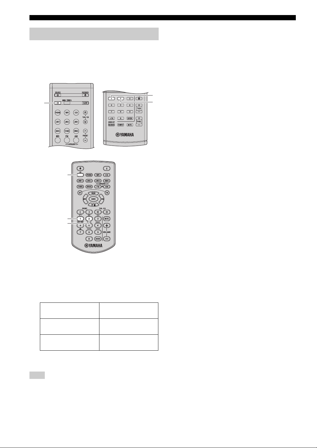
ADVANCED SETUP
Switching the remote control ID
When using multiple Yamaha receivers or amplifiers with
the same default code setting, you may unintentionally
operate those components simultaneously. In this case, set
one of the alternative codes for this unit to operate this
unit separately.
ID
ID
1
2
1
2
• Switching to ID1
Press and hold the ID button and the numeric button
“1” on the remote control together for about 3 seconds.
• Switching to ID2
Press and hold the ID button and the numeric button
“2” on the remote control together for about 3 seconds.
Remote control ID*
(this unit’s setting)
ID1
ID2
(default setting)
*
When you change the remote control ID, you must
change the remote control ID of this unit (see page 43).
Function
To operate this unit using
an alternative code.
To operate this unit using
the default code.
Note
If the remote control batteries are weak or removed, the remote
control ID will switch to the default setting (ID2). In this case,
replace the batteries and set the remote control ID again.
44 En
Page 49

ZONE 2
ZONE 2
Connecting Zone 2 components
This unit allows you to configure a multi-room audio system. The Zone 2 feature enables you to set this unit to reproduce
separate input sources in the main room and in Zone 2 (the second room) simultaneously. You can control this unit from
the second room using the supplied remote control.
The R-S700 can also be operated using the supplied Zone 2 remote control.
You need the following additional equipment to use the multi-room system of this unit:
• An infrared signal receiver for the second room.
• An infrared emitter for the main room. This emitter transmits the infrared signals sent by the remote control in Zone 2
to the components in the main room.
• An amplifier and speakers for the second room.
y
Some Yamaha models are able to connect directly to the REMOTE OUT jack on the rear panel of this unit. If you own one of these
products, you may not need to use an infrared emitter. Up to six Yamaha components can be connected as shown below.
REMOTE
Infrared signal
receiver
IN
This unit
REMOTE
IN
Yamaha component
REMOTE
OUT
IN
Yamaha component
REMOTE
OUTOUT
■ Multi-room configuration and connections
The following illustration shows an example of a multi-room system configuration and connections.
Amplifier
CD changer
(or other components)
Infrared emitter
Main room (Main Zone)
y
Since there are many possible ways to connect and use this unit in a multi-room configuration, we recommend that you consult with
your nearest authorized Yamaha dealer or service center for the Zone 2 connections that best meet your requirements.
This unit
Zone 2
Remote control
(R-S700 only)
Second room (Zone 2)
Infrared signal
receiver
OPERATION
ADVANCED
Note
If you want to adjust the Zone 2 volume level by using the amplifier in the second room, we recommend setting the Zone 2 volume level
to or near 2.5 dB.
45 En
Page 50

ZONE 2
Controlling Zone 2
■ Using the remote control
Use the supplied remote control, Zone 2 remote control
(R-S700 only) or front panel to control the input source or
adjust the sound output level of Zone 2 independently of
the listening conditions in the main room.
*
Sound output level can be adjusted on the R-S700 only.
Note
When using the R-S500, follow the procedure described in
“Using the remote control” and “Using the front panel”.
■ Using the Zone 2 remote control (R-S700
only)
(Zone 2 on)
1
2
MAIN/
ZONE 2
1 Change the zone that is operated by the
remote control.
• To control the Main zone
Press and hold the MAIN/ZONE 2 button and the
numeric button 1 on the remote control together for
about 3 seconds.
• To control Zone 2
Press and hold the MAIN/ZONE 2 button and the
numeric button 2 on the remote control together for
about 3 seconds.
2 Use the remote control as desired.
For information about the buttons that can be used to
control Zone 2, see “Remote control” on page 8.
Buttons that can be used to control Zone 2 are
indicated by “ ” on page 8.
1 Press (Zone 2 on) on the Zone 2 remote
control to turn on Zone 2.
2 Use the Zone 2 remote control as desired.
For information about each of the buttons on the
Zone 2 remote control, see “Zone 2 remote control
(R-S700 only)” on page 10.
■ Using the front panel
ZONE 2 CONTROL
ZONE 2
1 Press ZONE 2 on the front panel to turn on
Zone 2.
2 Press ZONE 2 CONTROL on the front panel
to control Zone 2.
The ZONE 2 indicator on the front panel display
blinks for about 10 seconds. During this time, you
can control Zone 2 from the front panel.
For information about the buttons and controls that
can be used to control Zone 2, see “Front panel” on
page 4. Buttons and controls that can be used to
control Zone 2 are indicated by “ ” on page 4.
46 En
Page 51

REMOTE CONTROL FEATURES
REMOTE CONTROL FEATURES
The remote control can be used to control not only this unit, but also seven other audio-visual components (TV, DVD
player, VCR, etc.) made by Yamaha and other manufacturers. To control other components with this unit’s remote
control, you must first configure the remote control to control each component (see page 49).
Controlling this unit, a TV, or other components
■ Controlling this unit
*1
OPTION
*2
*1
These buttons always control this unit.
*2
These buttons control this unit only when OPTION is pressed.
■ Controlling a TV
To use this unit’s remote control to control your TV,
determine the remote control code that corresponds to
your TV and assign that code to the TV A button or to
another input selector button on the remote control. For
details about assigning remote control codes, see page 49.
*1
TV A
*2
OPERATION
ADVANCED
*1
These buttons control your TV if your TV’s remote control
code has been assigned to an input selector button.
*2
These buttons (described below) control your TV if your TV’s
remote control code has been assigned to the TV A button or to
an input selector button.
TV control button Function
TV A
TV CH +/– Changes the TV’s channel.
TV VOL +/– Adjusts the TV’s volume.
TV INPUT
MUTE
Turns the TV on and off.
Changes the TV’s input source.
Mutes the TV’s audio output.
47 En
Page 52

REMOTE CONTROL FEATURES
Notes
• When using only one TV: Assign the TV’s remote control code
to the TV A button. The TV control buttons always control your
TV, regardless of the selected input source.
• To use other buttons (*1, above) to control your TV: Assign the
TV’s remote control code to the TV A button, and also to an
input selector button. The TV control buttons always control
your TV, regardless of the selected input source. You can use
the other buttons to operate the TV by first pressing the input
selector button to which the TV is assigned.
• To control more than one TV: Assign one TV to the TV A
button and the other TVs to other input selector buttons. You
can control the other TVs assigned by first pressing the input
selector button to which a TV is assigned. You can use the TV
control buttons to control the first TV whenever an input
selector button with no TV assigned to it is selected.
■ Controlling other components
To use this unit’s remote control to control other
components (DVD player, VCR, etc.), determine the
remote control code that corresponds to the component
and assign that code to the desired input selector button on
the remote control. For details about assigning remote
control codes, see page 49.
To switch the input source and control the corresponding
component, press the input selector button on the remote
control, and then press the desired control button.
y
If you are unable to operate this unit after using the remote
control to operate an external component, press RECEIVER and
then try operating the remote control again.
The following table is an example of the component
features that may be controlled using this remote control.
Note that some features of the corresponding component
may not be supported, and that some buttons may not
correctly control the selected component.
Remote control Feature (example)
[1] SOURCE A Power
[2] TOP MENU Title
[3] B Up
C Down
D Left
E Right
ENTER Enter
[4] RETURN Return
[5] DISC SKIP/REC Disc skip (player)
p Play
w Search backward
f Search forward
e /A/B
b /DIR A
a /DIR B
s Stop
[6] 1-9, 0, +10 Numeric buttons
[7] MENU Menu
[8] DISPLAY Display
[9] ENTER Title/Index
Rec (recorder)
Pause (player, recorder)
Deck A/B (tape deck)
Skip backward (player, recorder)
Direction A (tape deck)
Skip forward (player, recorder)
Direction B (tape deck)
[1]
[2]
[3]
[4]
[5]
[6]
Input selector
buttons
[7]
[8]
[9]
RECEIVER
48 En
Page 53

Configuring the remote control
To use this unit’s remote control to control other
components (TV, DVD player, VCR, etc.), determine the
remote control code that corresponds to the component
and assign that code to the desired input selector button on
the remote control. Remote control codes are listed in the
“LIST OF REMOTE CONTROL CODES” at the end of
this manual.
REMOTE CONTROL FEATURES
■ Assigning remote control codes
1 Refer to the “LIST OF REMOTE CONTROL
CODES” at the end of this manual and
determine the remote control code that
corresponds to each of your components.
Components are listed by category (TV, VCR, DVD
player, etc.) and manufacturer.
2 Press and hold CODE SET on the remote
control for more than 3 seconds.
Input selector
buttons
OPTION
TV A
Numeric
buttons
CODE SET
■ Default remote control configuration
The remote control is configured at the factory as shown
below.
Button
CD CD player Yamaha 5082
TAPE TAPE deck Yamaha 5087
PHONO — — —
LINE 1 CD recorder Yamaha 5083
LINE 2 DVD player Yamaha 2082
Component
category
Manufacturer
Default
code
3 Press an input selector button on the remote
control to select the input source you want to
configure.
You can also press TV A to configure the TV control
buttons (see page 47).
4 Use the numeric buttons on the remote
control to enter the four-digit remote control
code corresponding to the component you
want to assign.
When the component has been assigned, “OK” is
displayed on the front panel display. If an error
occurs, “NG” is displayed.
Notes
• If the manufacturer of your component has more than one
remote control code, assign each code one at a time until you
find the code that successfully controls your component.
• You can only assign one remote control code to each input
selector button.
■ Resetting the remote control
Use this procedure to reset the remote control codes
assigned to each input selector to the factory default (see
“Default remote control configuration” above).
Note
This procedure will be cancelled if you do not press any buttons
for 1 minute. If the procedure is cancelled, repeat from step 1 if
necessary.
OPERATION
ADVANCED
LINE 3
TV A ———
Blu-ray disc
player
Yamaha 2064
Note
If you cannot operate a Yamaha component when the remote
control is configured using the remote control code listed above,
refer to the “LIST OF REMOTE CONTROL CODES” at the end
of manual and try assigning a different Yamaha remote control
code.
1 Press and hold CODE SET on the remote
control for more than 3 seconds.
2 Press OPTION on the remote control.
3 Use the numeric buttons on the remote
control to enter “9981”.
The remote control code assigned to each input
selector button will be reset to its factory default
code.
49 En
Page 54

TROUBLESHOOTING
TROUBLESHOOTING
Refer to the chart below if this unit does not function properly. If the problem you are experiencing is not listed below or
if the instructions below do not help, set this unit to standby mode, disconnect the power cable, and contact the nearest
authorized Yamaha dealer or service center.
■ General
Problem Cause Remedy
This unit fails to turn
on.
No sound Incorrect input or output cable
The sound suddenly
goes off.
Only the speaker on
one side can be
heard.
There is a lack of bass
and no ambience.
The power cable is not connected or the
plug is not completely inserted.
The impedance setting is incorrect. Set the impedance to match your speakers.
The protection circuitry has been activated
because of a short circuit, etc.
The IMPEDANCE SELECTOR switch on
the rear panel is not set to either end.
This unit has been exposed to a strong
external electric shock (such as lightning
or strong static electricity).
connections.
No appropriate input source has been
selected.
The SPEAKERS A/B switches are not set
properly.
Speaker connections are not secure. Secure the connections.
Output has been muted. Turn off the mute.
The MaxVol or IniVol setting is set too
low.
The component corresponding to the
selected input source is turned off or is not
playing.
The protection circuitry has been activated
because of a short circuit, etc.
This unit has become too hot. Make sure the openings on the top panel are not
The automatic power down function has
turned this unit off.
Incorrect cable connections. Connect the cables properly. If the problem persists,
Incorrect setting for the BALANCE
control.
The + and – wires are connected in
reverse at the amplifier or the speakers.
Connect the power cable firmly.
Check that the speaker wires are not touching each
other and then turn the power of this unit back on.
Set the IMPEDANCE SELECTOR switch to either
end when the power of this unit is turned off.
Set this unit to standby mode, disconnect the power
cable, plug it back in after 30 seconds, then use it
normally.
Connect the cables properly. If the problem persists,
the cables may be defective.
Select an appropriate input source with the INPUT
selector on the front panel (or one of the input
selector buttons on the remote control).
Turn on the corresponding SPEAKERS A or
SPEAKERS B.
Set the setting to a higher value.
Turn the component on and make sure it is playing.
Check that the IMPEDANCE SELECTOR switch is
set to the correct position.
Check that the speaker wires are not touching each
other and then turn the power of this unit back on.
blocked.
Change the automatic power down setting (“APD
TIMER” in the Advanced Setup menu) to a longer
setting, or disable the automatic power down function
by setting the POWER MANAGEMENT switch on
the rear panel to OFF.
the cables may be defective.
Set the BALANCE control to the appropriate
position.
Connect the speaker wires to the correct + and –
phase.
See
page
—
13
12
13
—
12
16
16
12
8
40
—
13
12
—
43
12
18
12
50 En
Page 55

TROUBLESHOOTING
Problem Cause Remedy
A “humming” sound
can be heard.
The volume level is
low while playing a
record.
The volume level
cannot be increased,
or the sound is
distorted.
The sound is
degraded when
listening with the
headphones
connected to the CD
player or the tape
deck connected to
this unit.
The sound level is
low.
The input source
cannot be changed
although the INPUT
selector is rotated.
Using the BASS,
TREBLE, BALANCE
and LOUDNESS
controls does not
affect the tonal
quality.
Incorrect cable connections. Connect the audio plugs firmly. If the problem
No connection from the turntable to the
GND terminal.
The record is being played on a turntable
with an MC cartridge.
The component connected to the TAPE
REC or LINE 1 REC output jacks of this
unit is turned off.
The power of this unit is turned off, or this
unit is set to standby mode.
The loudness control function is
operating.
The CD DIRECT AMP switch is turned
on (R-S700 only).
The CD DIRECT AMP (R-S700 only) or
the PURE DIRECT switch is turned on.
persists, the cables may be defective.
Make the GND connection between the turntable and
this unit.
The turntable should be connected to this unit through
the MC head amplifier.
Turn on the power of the component.
Turn on the power of this unit.
Turn down the volume, set the LOUDNESS control
to the FLAT position, and then adjust the volume
again.
Turn off the CD DIRECT AMP switch.
The CD DIRECT AMP or the PURE DIRECT switch
must be turned off to use those controls.
See
page
12
12
—
—
16
18
17
17
51 En
INFORMATION
ADDITIONAL
Page 56

TROUBLESHOOTING
■ Tuner
Problem Cause Remedy
FM stereo
reception is
noisy.
There is
distortion, and
clear reception
cannot be
FM
obtained even
with a good FM
antenna.
The desired
station cannot
be tuned in
with the
automatic
tuning method.
NO PRESETS
is displayed.
FM/
WRONG
AM
STATION is
displayed.
The desired
station cannot
be tuned in
with the
automatic
tuning method.
Automatic
station preset
AM
does not work.
There are
continuous
crackling and
hissing noises.
There are
buzzing and
whining noises.
The particular characteristics of the FM
stereo broadcasts being received may
cause this problem when the transmitter is
too far away or the antenna input is poor.
There is multipath interference. Adjust the antenna position to eliminate the multipath
The signal is too weak. Try using a high-quality directional FM antenna.
No preset stations are registered. Register stations you want to listen to as preset
An invalid FM/AM frequency has been
input.
The signal is weak or the antenna
connections are loose.
Automatic station preset is not available
for AM stations.
The noises may result from lightning,
fluorescent lamps, motors, thermostats or
other electrical equipment.
A TV set is being used nearby. Move this unit away from the TV set.
Check the antenna connections.
Try using a high-quality directional FM antenna.
Switch to monaural mode.
interference.
Try using the manual tuning method.
stations before operation.
Input a frequency that can be received.
Tighten the AM loop antenna connections and orient
it for the best reception.
Try using the manual tuning method.
Use manual station preset.
Try using an outdoor antenna and a ground wire.
This will help somewhat, but it is difficult to
eliminate all noise.
See
page
14
21
—
14
21
22
21
—
21
23
—
—
52 En
Page 57

■ SIRIUS Satellite Radio
TM
The following messages may be displayed on the front panel display in certain situations.
TROUBLESHOOTING
Message Status/Cause Remedy
ANTENNA ERROR The antenna is not connected to the
SIRIUS LOADING This unit is communicating with the
CHECK SR TUNER The SiriusConnect tuner is not connected
NOT SUPPORTED This unit does not support the connected
ACQUIRING The signal is too weak. Adjust the orientation of the antenna of the
UPDATING The SiriusConnect tuner is updating the
F/W UPDATING The SiriusConnect tuner is updating the
CALL SIRIUS
(CALL 888-539SIRIUS TO
SUBSCRIBE)
SUB UPDATED The subscription information is updated.
INVALID The selected channel is currently out of
NOT AVAILABLE The operation you made is not available.
SiriusConnect tuner properly.
SiriusConnect tuner.
to the SIRIUS jack of this unit correctly.
The SiriusConnect tuner is not connected
to the AC wall outlet.
SIRIUS Satellite Radio tuner.
channel list.
The period of the subscription is end. Contact SIRIUS Satellite Radio to renew the
firmware.
The selected channel is not subscribed. Contact SIRIUS Satellite Radio to subscribe the
service.
Check the connection of the antenna and
SiriusConnect tuner.
The message disappears normally within several tens
of seconds.
Check the connection of the SiriusConnect tuner and
this unit.
Connect the power cable of the SiriusConnect tuner
to the AC wall outlet.
Connect the SiriusConnect tuner that this unit
supports,
SiriusConnect tuner. Check the antenna reception
level from the Antenna information on the front
panel display.
Wait until the updating is complete.
subscription.
Wait until the updating is complete.
selected channel.
URL: https://activate.siriusradio.com/
Phone: 1-888-539-SIRIUS (1-888-539-7474)
Select another channel.
Select another channel.
See
page
27
—
27
—
—
34
—
—
—
—
28
—
28
—
INFORMATION
ADDITIONAL
53 En
Page 58

TROUBLESHOOTING
■ iPhone/iPod
The following messages may be displayed on the front panel display in certain situations.
Message Status/Cause Remedy
Connect error There is a problem with the signal path
from your iPhone/iPod to the unit.
Unknown iPod The iPhone/iPod being used is not
supported by the unit.
Connected Your iPhone/iPod is properly placed in
the Universal Dock for iPod.
Your iPhone/iPod is properly placed in
the Wireless System for iPod and
connected with this unit via wireless
transmission.
Disconnected Your iPhone/iPod is removed from the
Universal Dock for iPod.
Your iPhone/iPod is disconnected with
this unit via wireless transmission.
The wireless connection is poor. Place the YID-W10 receiver as far away from this
Turn off the unit and reconnect the Universal Dock
for iPod to the DOCK jack of the unit.
Remove your iPhone/iPod from the Universal Dock
for iPod and then place it back in the dock.
Connect an iPhone/iPod supported by the unit.
unit as possible.
Problem Cause Remedy
When using the
Universal Dock for
iPod:
Your iPhone/iPod is
not being charged
even though it is
connected to the
Universal Dock for
iPod.
When using the
Wireless System for
iPod:
Your iPhone/iPod is
not being charged
even though the YIDW10 transmitter
connected to your
iPhone/iPod is
stationed in the YIDW10 receiver.
The iPhone/iPod is not connected
securely.
The YID-W10 transmitter is not stationed
securely in the YID-W10 receiver.
Connect the iPhone/iPod securely to the Universal
Dock for iPod.
Station the YID-W10 transmitter connected to your
iPhone/iPod securely in the YID-W10 receiver.
See
page
35
35
35
—
37
—
—
35
See
page
—
—
54 En
Page 59

■ Bluetooth™
The following messages may be displayed on the front panel display in certain situations.
TROUBLESHOOTING
Message Status/Cause Remedy
Searching... The Bluetooth Wireless Audio Receiver
and the Bluetooth component are in the
process of pairing.
The Bluetooth Wireless Audio Receiver
and the Bluetooth component are in the
process of establishing a connection.
Completed The pairing is completed.
Canceled The pairing is canceled.
Connected The connection between the Bluetooth
Wireless Audio Receiver and the
Bluetooth component is established.
Disconnected The Bluetooth component is
disconnected from the Bluetooth Wireless
Audio Receiver.
Not found The Bluetooth component is not found. During pairing:
– pairing must be performed on the Bluetooth
component and this unit simultaneously. Check if
the Bluetooth component is in pairing mode.
During connecting:
– check if the Bluetooth component is turned on.
– check if the Bluetooth component is within 10 m
(32 feet) of the Bluetooth Wireless Audio
Receiver.
Pairing may not have been achieved. Try pairing again.
See
page
—
—
—
—
—
—
—
38
55 En
INFORMATION
ADDITIONAL
Page 60

TROUBLESHOOTING
■ Remote control
Problem Cause Remedy
The remote control
does not work nor
function properly.
Wrong distance or angle. The remote control will function within a maximum
Direct sunlight or lighting (from an
inverter type of fluorescent lamp, etc.) is
striking the remote control sensor of this
unit.
The batteries are weak. Replace all batteries.
The remote control ID and this unit’s ID
do not match.
The remote control code was not correctly
set.
Even if the remote control code is
correctly set, there are some models that
do not respond to the remote control.
You did not press the input selector button
corresponding to the component you are
trying to control.
The remote control is not set to the correct
zone.
If the remote control batteries are weak or
removed, the remote control ID and zone
will switch to the default settings (ID2 and
Main zone).
range of 6 m (20 ft) and no more than 30 degrees offaxis from the front panel.
Reposition this unit.
Switch the remote control ID or this unit’s ID.
Try setting another code of the same manufacturer
using “LIST OF REMOTE CONTROL CODES” at
the end of this manual.
Use the supplied remote control for the components.
Press the input selector button corresponding to the
component you are trying to control, and then press
the desired remote control button(s).
Set the remote control to the correct zone, the Main
zone or Zone 2, and then operate the remote control.
Replace all batteries, and then set the remote control
ID and zone again.
See
page
11
—
11
44
49
—
—
46
44, 46
56 En
Page 61

SPECIFICATIONS
SPECIFICATIONS
AUDIO SECTION
• Minimum RMS output power
[R-S700]
(8 Ω, 20 Hz to 20 kHz, 0.019% THD) .............. 100 W + 100 W
(6 Ω, 20 Hz to 20 kHz, 0.03% THD) ................ 120 W + 120 W
[R-S500]
(8 Ω, 20 Hz to 20 kHz, 0.04% THD) .................... 75 W + 75 W
• Dynamic power per channel (IHF)
(8/6/4/2 Ω)
[R-S700] ..................................................... 140/170/220/290 W
[R-S500] ..................................................... 105/125/150/178 W
• Maximum power per channel [Europe model only]
(1 kHz, 0.7% THD, 4 Ω)
[R-S700] .......................................................................... 160 W
[R-S500] .......................................................................... 105 W
• IEC power [Europe model only]
[R-S700] (1 kHz, 0.019% THD, 8 Ω) ................................ 115 W
[R-S500] (1 kHz, 0.04% THD, 8 Ω) .................................... 84 W
• Power band width
[R-S700] (0.06% THD, 50 W, 8 Ω) .................... 10 Hz to 50 kHz
[R-S500] (0.06% THD, 37.5 W, 8 Ω) ................. 10 Hz to 50 kHz
• Damping factor (SPEAKERS A)
1 kHz, 8 Ω
[R-S700] ................................................................. 240 or more
[R-S500] ................................................................. 150 or more
• Maximum effective output power (JEITA)
[Asia (R-S500 only) and Central/South America models only]
[R-S700] (1 kHz, 10% THD, 8/6 Ω) ........................ 145/170 W
[R-S500] (1 kHz, 10% THD, 8 Ω) .................................. 115 W
• Input sensitivity/Input impedance
PHONO (MM) ....................................................... 3.5 mV/47 kΩ
CD, etc. ................................................................. 200 mV/47 kΩ
[R-S700] MAIN IN .................................................... 1.0 V/47 kΩ
• Maximum input signal
PHONO (MM) (1 kHz, 0.003% THD) ................. 60 mV or more
CD, etc. (1 kHz, 0.5% THD) .................................. 2.2 V or more
• Output level/Output impedance
CD, etc. (Input 1 kHz, 200 mV)
REC .................................................................. 200 mV/1.0 kΩ
CD, etc. (Input 1 kHz, 200 mV, 8 Ω)
PHONES ............................................................ 410 mV/470 Ω
• Frequency response
CD, etc. (20 Hz to 20 kHz) ........................................... 0 ± 0.5 dB
[R-S700] CD, etc., PURE DIRECT on/MAIN IN
(10 Hz to 100 kHz) .................................................... 0 ± 1.0 dB
[R-S500] CD, etc., PURE DIRECT on
(10 Hz to 100 kHz) .................................................... 0 ± 1.0 dB
• RIAA equalization deviation
PHONO (MM) ................................................................. ± 0.5 dB
• Total harmonic distortion
PHONO (MM) to REC
(20 Hz to 20 kHz, 3 V) .......................................... 0.025% or less
[R-S700]
CD, etc. to PRE OUT
(20 Hz to 20 kHz, 1 V) ....................................... 0.005% or less
CD, etc. to SPEAKERS
(20 Hz to 20 kHz, 50 W, 8 Ω) ............................. 0.015% or less
[R-S500]
CD, etc. to SPEAKERS
(20 Hz to 20 kHz, 37.5 W, 8 Ω) .......................... 0.015% or less
• Signal to noise ratio (IHF-A network)
PHONO (MM) (5 mV input shorted) .................... 87 dB or more
CD, etc., PURE DIRECT on
(200 mV input shorted) ..................................... 100 dB or more
[R-S700] CD, CD DIRECT AMP on
(200 mV input shorted) ..................................... 107 dB or more
• Residual noise (IHF-A network) ........................................... 30 µV
• Channel separation
CD, etc. (5.1 kΩ input shorted, 1/10 kHz) ........ 65/50 dB or more
• Tone control characteristics
BASS
Boost/Cut (50 Hz) ......................................................... ± 10 dB
Turnover Frequency ........................................................ 350 Hz
TREBLE
Boost/Cut (20 kHz) ....................................................... ± 10 dB
Turnover Frequency ....................................................... 3.5 kHz
• Continuous loudness control
Attenuation (1 kHz) ............................................................ –30 dB
• Gain tracking error (0 to –99 dB) ............................... 0.5 dB or less
FM SECTION
• Tuning range
[U.S.A. and Canada models] ........................... 87.5 to 107.9 MHz
[Asia (R-S500 only) and Central/South America models]
................................................. 87.5/87.50 to 107.9/108.00 MHz
[Europe, Russia and Australia models] ....... 87.50 to 108.00 MHz
• 50 dB quieting sensitivity (IHF, 1 kHz, 100% MOD.)
Mono ................................................................ 3.0 µV (20.8 dBf)
• Signal to noise ratio (IHF)
Mono/Stereo .............................................................. 74 dB/70 dB
• Harmonic distortion (1 kHz)
Mono/Stereo ................................................................ 0.3%/0.3%
AM SECTION
• Tuning range
[U.S.A. and Canada models] .............................. 530 to 1710 kHz
[Asia (R-S500 only) and Central/South America models]
.......................................................... 530/531 to 1710/1611 kHz
[Europe, Russia and Australia models] ............... 531 to 1611 kHz
GENERAL
• Power supply
[U.S.A. and Canada models] .............................. AC 120 V, 60 Hz
[Central/South America models]
............................................... AC 110-120/220-240 V, 50/60 Hz
[Australia model] ............................................... AC 240 V, 50 Hz
[Europe and Russia models] ............................... AC 230 V, 50 Hz
[Asia model (R-S500 only)]................... AC 220-240 V, 50/60 Hz
• Power consumption
[R-S700]
[U.S.A. and Canada models] .............................. 270 W, 370 VA
[Other models] ................................................................ 270 W
[R-S500]
[Asia model] .................................................................... 170 W
[Other models] ................................................................ 190 W
• Standby power consumption ....................................... 0.5 W or less
• YID-W10 standby power consumption
(YID-W10 connect) ................................................. 1.2 W or less
• iPod charge power consumption
[R-S700] .................................................................... 40 W or less
[R-S500] .................................................................... 35 W or less
• Maximum power consumption [Central/South America models
only]
[R-S700] (6 Ω , 1 kHz, 10% THD) ..................................... 570 W
[R-S500] (8 Ω , 1 kHz, 10% THD) .................................... 380 W
• Dimensions (W x H x D) ................................ 435 × 151 × 387 mm
(17-1/8" × 6" × 15-1/4")
•Weight
[R-S700] ............................................................ 11.2 kg (24.7 lbs)
[R-S500] ............................................................ 10.2 kg (22.5 lbs)
* Specifications are subject to change without notice.
INFORMATION
ADDITIONAL
57 En
Page 62

LIST OF REMOTE CONTROL CODES
TV
A.R. Systems 0320
Acme 0342
Acura 0323, 0343
ADC 0337
Admiral 0054, 0178, 0336,
0337, 0339, 0346,
0347
Advent 0158
Adventura 0057
Adyson 0277, 0282, 0342
Agashi 0277, 0282
Agazi 0337
Aiko 0277, 0282, 0320,
0323, 0342, 0343
Aim 0320
Aiwa 0078, 0379
Akai 0050, 0055, 0109,
0159, 0181, 0277,
0282, 0320, 0323,
0340, 0343, 0349,
0350
Akiba 0320, 0340
Akura 0320, 0323, 0337,
0340
Alaron 0277
Alba 0161, 0277, 0320,
0323, 0340, 0342,
0343, 0344, 0349,
0351, 0372, 0382
Albatron 0140
Alcyon 0171
Alleron 0059
Allorgan 0282
Allstar 0320, 0350
America Action 0179
AMOi 0276
Amplivision 0161, 0282, 0321,
0342
Amstrad 0320, 0323, 0337,
0340, 0343
Amtron 0058
Anam 0179, 0343
Anam National 0052, 0058
Anglo 0323, 0343
Anitech 0171, 0320, 0323,
0337, 0343
Ansonic 0161, 0168, 0320,
0323, 0341, 0343
AOC 0008, 0026, 0050,
0053
Apex 0039, 0111, 0217
Arcam 0277, 0282
Arcam Delta 0342
Aristona 0320, 0349, 0350
Arthur Martin 0321
ASA 0339, 0347
Asberg 0171, 0320, 0350
Astra 0343
Asuka 0277, 0282, 0337,
0340, 0342
Atlantic 0277, 0320, 0342,
0349, 0350
Atori 0323, 0343
Auchan 0321
Audiosonic 0161, 0282, 0320,
0340, 0342, 0343,
0349, 0350
AudioTon 0161, 0282, 0342
Audiovox 0058, 0179, 0194
Ausind 0171
Autovox 0171, 0282, 0337,
Aventura 0051
Awa 0277, 0282
Axion 0156
Baird 0282
Bang & Olufsen 0180, 0339
Basic Line 0282, 0320, 0323,
Bastide 0282, 0342
Baur 0320, 0349
Bazin 0282
Beko 0161, 0269, 0294,
Belcor 0008
Bell & Howell 0019, 0054
Benq 0097, 0242, 0361
Beon 0320, 0349, 0350
Best 0161
Bestar 0161, 0320, 0350
Binatone 0282, 0342
Blue Sky 0320, 0340
Blue Star 0348
Boots 0282, 0342
BPL 0320, 0348
Bradford 0058, 0179
Brandt 0322, 0345
Brillian 0182
Brinkmann 0320
Brionvega 0320, 0339, 0349,
Britannia 0277, 0282, 0342
Brockwood 0008
Broksonic 0109, 0179
Bruns 0339
BTC 0340
Bush 0269, 0282, 0283,
Candle 0008, 0026, 0050,
Capsonic 0337
Carena 0320
Carnivale 0050
Carrefour 0344
Carver 0010
Cascade 0320, 0323, 0343
Casio 0367
Cathay 0320, 0349, 0350
CCE 0183, 0282
Celebrity 0055, 0107
Celera 0039
Centurion 0320, 0349, 0350
Century 0339
CGE 0161, 0171
Changhong 0039
Chimei 0273
Cimline 0323, 0343
Citizen 0007, 0008, 0026,
City 0323, 0343
Clarion 0179
Clarivox 0349
Clatronic 0161, 0171, 0282,
CMS 0277
CMS Hightec 0282
0339, 0342
0340, 0343, 0350
0302, 0311, 0320,
0328, 0351
0350
0304, 0320, 0323,
0328, 0332, 0340,
0343, 0344, 0346,
0348, 0349, 0350,
0372, 0382, 0463,
0470, 0472
0057
0050, 0058
0320, 0323, 0337,
0340, 0342, 0343,
0350, 0351
Coby 0197
Colortyme 0008, 0026
Commercial Solutions
0021
Concerto 0008, 0026
Concorde 0323, 0343
Condor 0161, 0277, 0320,
0323, 0342, 0350,
0351
Contec 0179, 0277, 0323,
0342, 0343, 0344
Contec/Cony 0012, 0058
Continental Edison
0345
Cosmel 0323, 0343
Craig 0058, 0179
Crosley 0010, 0037, 0171,
0339
Crown 0058, 0161, 0171,
0179, 0320, 0323,
0343, 0349, 0350,
0351
CS Electronics 0277, 0340, 0342
CTC Clatronic 0341
CTX 0205
Curtis Mathes 0007, 0008, 0010,
0019, 0021, 0026,
0049, 0050, 0178
CXC 0058, 0179
Cybertron 0340
Cytron 0152
Daewoo 0007, 0008, 0026,
0037, 0053, 0167,
0266, 0275, 0277,
0282, 0315, 0320,
0323, 0331, 0335,
0342, 0343, 0350,
0381, 0465
Dainichi 0277, 0340
Dansai 0277, 0282, 0320,
0337, 0349, 0350
Dantax 0161, 0349
Dawa 0320
Daytron 0007, 0008, 0026,
0323, 0343
De Graaf 0346
Decca 0282, 0320, 0342,
0349, 0350
Dell 0145, 0245
Denver 0358, 0362
Desmet 0320, 0349, 0350
Diamant 0320
Diamond 0277
DiamondVision 0135, 0143
Dimensia 0049
Disney 0219
Dixi 0282, 0320, 0323,
0343, 0349, 0350
Dream Vision 0461, 0498
DTS 0323, 0343
Dual 0282, 0320, 0342
Dual-Tec 0342, 0343
Dumont 0008, 0030, 0062,
0282, 0339, 0341,
0342
Durabrand 0031, 0051, 0179,
0215
Dux 0349
Dwin 0178
Dynatron 0320, 0349, 0350
Dynex 0228, 0231
Elbe 0161, 0168, 0282,
0320
Elcit 0339
Electa 0348
ELECTRO TECH
Electroband 0055, 0107
Electrograph 0176
Electrohome 0008, 0026, 0052,
Element 0230
Elin 0277, 0320, 0323,
Elite 0320, 0340, 0350
Elman 0341
Elta 0277, 0323, 0343
Emerson 0000, 0007, 0008,
Emprex 0154
Envision 0008, 0026, 0050
Epson 0155, 0206, 0359
Erres 0320, 0349, 0350
ESA 0051
ESC 0282
Etron 0343
Eurofeel 0282
Euro-Feel 0337
Euroline 0349
Euroman 0161, 0277, 0282
Euromann 0320, 0337, 0342,
Europhon 0277, 0282, 0320,
Expert 0321
Exquisit 0320
Fenner 0323, 0343
Ferguson 0322, 0345, 0349
Fidelity 0277, 0320, 0342,
Filsai 0282
Finlandia 0346
Finlux 0171, 0282, 0320,
FIRST LINE 0342, 0343, 0350
Firstline 0277, 0282, 0320,
Fisher 0019, 0161, 0282,
Flint 0320, 0350
Formenti 0171, 0277, 0336,
Formenti/Phoenix
Fortress 0336, 0339
Fraba 0161, 0320
Friac 0161
Frontech 0282, 0323, 0337,
Fujitsu 0059, 0069, 0074,
Fujitsu General 0282
Fujitsu Siemens 0504, 0505, 0507,
Funai 0051, 0058, 0059,
Futuretech 0058, 0179
Galaxi 0320, 0351
Galaxis 0161, 0320
Gateway 0176, 0177, 0241
GBC 0323, 0343, 0344
0343
0055
0342, 0349, 0350
0012, 0013, 0019,
0026, 0031, 0037,
0051, 0058, 0059,
0161, 0179, 0320,
0339
0350
0341, 0342, 0350
0346
0339, 0341, 0342,
0349, 0350
0323
0339, 0342, 0344,
0351
0339, 0342, 0349
0277
0343, 0346, 0347
0075, 0282
0510, 0511
0112, 0113, 0115,
0118, 0119, 0179,
0337
i
Page 63

GE 0008, 0021, 0023,
0026, 0027, 0031,
0034, 0049, 0052,
0056, 0209
Geant Casino 0321
GEC 0282, 0320, 0342,
0347, 0349, 0350
Geloso 0323, 0343, 0346
General Technic0323, 0343
Genexxa 0320, 0340, 0347,
0350
GFM 0128, 0227
Giant 0282
Gibralter 0008, 0030, 0050,
0062
GoldHand 0277
Goldline 0320
GoldStar 0007, 0008, 0012,
0026, 0031, 0050,
0053, 0161, 0277,
0282, 0320, 0323,
0342, 0343, 0346,
0349, 0350
Goodmans 0246, 0272, 0282,
0320, 0323, 0337,
0343, 0344, 0349,
0350, 0462, 0473,
0477
Gorenje 0161, 0351
GPM 0340
GPX 0129
Gradiente 0240
Graetz 0347
Granada 0171, 0282, 0320,
0321, 0342, 0344,
0346, 0349, 0350
Grandin 0340, 0343, 0348,
0349
Gronic 0282
Grundig 0160, 0161, 0171,
0310, 0320
Grunpy 0058, 0059, 0179
Haier 0157, 0233
Halifax 0277, 0282, 0337,
0342
Hallmark 0008, 0026, 0031
Hampton 0277, 0282, 0342
Hanseatic 0161, 0168, 0282,
0320, 0323, 0342,
0343, 0344, 0349,
0350
Hantarex 0320, 0323, 0343
Hantor 0320
Harman/Kardon 0010
Harvard 0058, 0179
Harwood 0320, 0323
Havermy 0178
HCM 0282, 0320, 0323,
0337, 0342, 0343,
0348
Hema 0282, 0323
Hewlett Packard0192
Higashi 0277
HiLine 0320
Hinari 0320, 0323, 0340,
0343, 0344, 0349,
0350
Hisawa 0321, 0340, 0348
Hisense 0247
Hitachi 0008, 0012, 0026,
0066, 0084, 0092,
0093, 0120, 0172,
0173, 0255, 0270,
0271, 0282, 0320,
0335, 0338, 0342,
0344, 0346, 0347,
0365, 0382, 0448,
0456, 0467
Hornyphon 0320, 0350
Hoshai 0340
Huanyu 0277, 0342
Hygashi 0277, 0282, 0342
Hyper 0277, 0282, 0323,
0342, 0343
Hypson 0282, 0320, 0321,
0337, 0342, 0348,
0349, 0350
Hyundai 0141
Iberia 0320
ICE 0277, 0282, 0320,
0323, 0337, 0340,
0342, 0343, 0350
ICeS 0277
Ilo 0148, 0153
IMA 0058
Imperial 0161, 0171, 0320,
0347, 0350, 0351
Indiana 0320, 0349, 0350
Infinity 0010
InFocus 0250, 0327, 0363,
0479, 0508
Ingelen 0347
Ingersol 0323, 0343
Initial 0153
Inno Hit 0171, 0282, 0320,
0323, 0340, 0342,
0343, 0349, 0350
Innovation 0337, 0343
Insignia 0131, 0228, 0236,
0238
Inteq 0030
Interactive 0161
Interbuy 0323, 0343
Interfunk 0161, 0320, 0339,
0347, 0349, 0350
International 0277
Intervision 0161, 0282, 0320,
0337, 0341, 0342
Irradio 0171, 0320, 0323,
0340, 0343, 0349,
0350
Isukai 0320, 0340
ITC 0282, 0342
ITS 0277, 0320, 0340,
0348, 0350
ITT 0343, 0347
ITV 0320, 0343, 0349
Janeil 0057
JBL 0010
JC Penney 0007, 0008, 0026,
0027, 0049, 0053,
0056
JCB 0055, 0107
Jensen 0008, 0026
JVC 0012, 0014, 0015,
0056, 0064, 0065,
0067, 0169, 0174,
0297, 0314, 0344,
0350, 0375
Kaisui 0277, 0282, 0320,
0323, 0340, 0342,
0343, 0348
Kamosonic 0342
Kamp 0277, 0342
Kapsch 0347
Karcher 0161, 0320, 0342,
Kawasho 0008, 0026, 0055,
KEC 0179
Kendo 0161, 0320, 0341,
Kenwood 0008, 0026, 0050
KIC 0282
Kingsley 0277, 0342
KLH 0039
Kloss Novabeam
Kneissel 0161, 0168, 0320
Kolster 0320, 0350
Konka 0340
Korpel 0320, 0349, 0350
Korting 0161, 0339
Kosmos 0320
Koyoda 0343
KTV 0007, 0050, 0058,
Kyoto 0277, 0282
Lasat 0161
Lenco 0323, 0343
Lenoir 0323, 0342, 0343
Leyco 0320, 0337, 0349,
LG 0031, 0053, 0066,
LG/GoldStar 0164
Liesenk 0349
Liesenkotter 0320
Life 0337, 0343
Lifetec 0320, 0323, 0337,
Lloyds 0323
Loewe 0161, 0168, 0265,
Loewe Opta 0339, 0349, 0350
Logik 0054
Luma 0320, 0323, 0346,
Lumatron 0282, 0320, 0346,
Lux May 0350
Luxman 0008, 0026
Luxor 0282, 0342, 0346
LXI 0010, 0019, 0021,
M Electronic 0342, 0343, 0345,
MAG 0096
Magnadyne 0339, 0341, 0349
Magnafon 0171, 0277, 0341,
Magnavox 0008, 0009, 0010,
Magnum 0337, 0343
Majestic 0054
Mandor 0337
0343, 0349
0277
0346
0057, 0058
0179, 0183, 0282,
0342
0350
0116, 0117, 0140,
0161, 0164, 0175,
0195, 0269, 0277,
0282, 0300, 0309,
0317, 0320, 0323,
0328, 0342, 0343,
0346, 0349, 0350,
0366, 0368, 0377,
0466, 0471, 0478
0343
0320, 0330, 0352
0349
0349, 0350
0026, 0027, 0031,
0049, 0111
0347, 0349, 0350
0342
0013, 0026, 0032,
0033, 0048, 0050,
0128, 0211, 0212,
0224, 0226, 0239
Manesth 0282, 0320, 0337,
0342, 0349, 0350
Marantz 0008, 0010, 0026,
0050, 0204, 0320,
0349, 0350
Marelli 0339
Mark 0277, 0282, 0320,
0323, 0349, 0350
Masuda 0282
Matsui 0282, 0320, 0323,
0342, 0343, 0344,
0346, 0349, 0350,
0455
Matsushita 0017
Maxent 0147, 0176
Mediator 0320, 0349, 0350
Medion 0320, 0337, 0343
Megapower 0140
Megatron 0026, 0031
MElectronic 0277, 0282, 0320,
0323
Melvox 0321
Memorex 0019, 0026, 0031,
0053, 0054, 0137,
0215, 0323, 0343
Memphis 0323, 0343
Mercury 0320, 0323
Metz 0339
MGA 0008, 0026, 0031,
0050, 0053
Micromaxx 0337, 0343
Microstar 0337, 0343
Midland 0007, 0021, 0023,
0027, 0030, 0056,
0062
Minerva 0171
Minoka 0320, 0350
Mintek 0153
Mitsubishi 0008, 0026, 0031,
0053, 0066, 0084,
0093, 0098, 0150,
0178, 0289, 0320,
0339, 0344, 0350,
0376
Mivar 0161, 0168, 0171,
0277, 0282, 0342
Monivision 0140
Montgomery Ward
0054
Motion 0171
Motorola 0052, 0178
MTC 0008, 0026, 0050,
0053, 0161, 0277
Multi System 0349
Multitech 0058, 0161, 0179,
0183, 0277, 0282,
0320, 0323, 0341,
0342, 0343, 0344,
0346, 0349
Murphy 0277, 0342
NAD 0026, 0031, 0111
Naonis 0346
NEC 0008, 0026, 0050,
0052, 0053, 0072,
0103, 0282, 0344
Neckermann 0161, 0282, 0320,
0339, 0342, 0346,
0349, 0350, 0351
NEI 0320, 0349, 0350
Net-TV 0176
Neufunk 0320, 0323
New Tech 0343, 0350
New World 0340
NewTech 0282, 0320, 0323
Nicamagic 0277, 0342
ii
Page 64

Nikkai 0277, 0282, 0320,
0323, 0337, 0340,
0342, 0349, 0350
Nikko 0026, 0031, 0050
Nobliko 0171, 0277, 0341,
0342
Nokia 0347
Norcent 0201
Nordic 0282
Nordmende 0339, 0345, 0347,
0350
Nordvision 0349
Novatronic 0320
Oceanic 0321, 0347
Okano 0161, 0320, 0351
Olevia 0102, 0199, 0200,
0207, 0222
ONCEAS 0342
Onwa 0058, 0179
Opera 0320
Oppo 0130
Optimus 0017, 0019
Optoma 0144
Optonica 0178
Orbit 0320, 0350
Orion 0043, 0146, 0283,
0320, 0323, 0328,
0343, 0349, 0350
Orline 0320
Osaki 0282, 0320, 0337,
0340, 0342
Oso 0340
Otto Versand 0282, 0320, 0336,
0342, 0344, 0348,
0349, 0350
Pael 0277, 0342
Palladium 0161, 0282, 0320,
0342, 0351
Palsonic 0282
Panama 0277, 0282, 0320,
0323, 0337, 0342,
0343
Panasonic 0016, 0017, 0020,
0022, 0023, 0035,
0052, 0056, 0084,
0085, 0133, 0163,
0193, 0284, 0286,
0290, 0292, 0320,
0325, 0347, 0356
Panavision 0320
Pathe Cinema 0161, 0168, 0277,
0321, 0342
Pausa 0323, 0343
Penney 0021, 0023, 0031,
0050, 0111
Perdio 0277, 0320
Perfekt 0320
Philco 0008, 0009, 0010,
0012, 0026, 0050,
0052, 0053, 0161,
0171, 0320, 0339
Philharmonic 0282, 0342
Philips 0008, 0009, 0010,
Philips Magnavox
Phoenix 0161, 0277, 0320,
Phonola 0277, 0320, 0339,
Pilot 0007, 0008, 0050
Pioneer 0008, 0026, 0094,
Plantron 0320, 0323, 0337,
Playsonic 0282
Polaroid 0039, 0142, 0202,
Poppy 0323, 0343
Portland 0007, 0008, 0026,
Prandoni-Prince 0171, 0346
Precision 0282, 0342
Prima 0157, 0243, 0323,
Princeton 0140
Prism 0023, 0056
Profex 0323, 0343
Profi-Tronic 0320, 0350
Proline 0320, 0350
Proscan 0021, 0027, 0049
Prosonic 0161, 0277, 0282,
Protech 0282, 0337, 0341,
Proton 0008, 0012, 0026,
Protron 0196
PROVIEW 0096, 0246
Provision 0320, 0349
Pulsar 0008, 0030, 0062
Pye 0256, 0320, 0349,
Pymi 0323, 0343
Quandra Vision 0321
Quasar 0017, 0023, 0052,
Quelle 0282, 0320, 0337,
Questa 0344
Radialva 0320
RadioShack 0019, 0021, 0031,
RadioShack/Realistic
Radiola 0282, 0320, 0349,
Radiomarelli 0320, 0339
0011, 0012, 0032,
0048, 0049, 0052,
0122, 0128, 0134,
0186, 0187, 0213,
0221, 0224, 0226,
0239, 0256, 0257,
0259, 0261, 0263,
0267, 0280, 0281,
0287, 0296, 0299,
0301, 0303, 0305,
0313, 0319, 0320,
0324, 0333, 0339,
0342, 0349, 0350,
0353, 0357, 0360,
0380, 0383, 0452,
0459, 0460
0011, 0032, 0033
0339, 0349, 0350
0349, 0350
0095, 0161, 0320,
0345, 0347, 0349,
0350, 0458
0350
0234
0053
0343, 0347
0320, 0342, 0349
0342, 0343, 0349,
0350
0031
0350, 0378
0056
0342, 0349, 0350
0050, 0179, 0320
0007, 0008, 0012,
0026, 0049, 0058
0350
Radiotone 0161, 0320, 0323,
0350
Rank 0344
RCA 0008, 0021, 0024,
0025, 0026, 0027,
0042, 0049, 0052,
0053, 0063, 0136,
0225
Realistic 0019, 0031, 0050,
0179
Recor 0320
Redstar 0320
Reflex 0320
Revox 0161, 0320, 0349,
0350
Rex 0337, 0346, 0347
RFT 0161, 0168, 0339
Rhapsody 0277
R-Line 0320, 0349, 0350
Roadstar 0323, 0337, 0340,
0343
Robotron 0339
Rowa 0277, 0282
Royal Lux 0161
RTF 0339
Runco 0030, 0050, 0062
Saba 0298, 0322, 0339,
0345, 0347
Saisho 0282, 0323, 0337,
0342, 0343
Salora 0346, 0347
Sambers 0171, 0341
Sampo 0007, 0008, 0026,
0050, 0176
Samsung 0004, 0005, 0006,
0007, 0008, 0012,
0026, 0031, 0036,
0050, 0053, 0076,
0077, 0079, 0114,
0124, 0125, 0126,
0127, 0139, 0161,
0183, 0185, 0190,
0191, 0258, 0264,
0277, 0282, 0320,
0323, 0334, 0337,
0342, 0343, 0349,
0350, 0351, 0373,
0453, 0468
Sandra 0277, 0282, 0342
Sansui 0043, 0109, 0320,
0350
Sanyo 0008, 0019, 0068,
0070, 0071, 0099,
0161, 0168, 0223,
0237, 0277, 0282,
0288, 0295, 0323,
0342, 0344, 0369,
0469
SBR 0320, 0349
Sceptre 0235, 0244
Schaub Lorenz 0347
Schneider 0282, 0316, 0318,
0320, 0333, 0340,
0342, 0349, 0350,
0382
Scotch 0026, 0031
Scott 0008, 0012, 0026,
0031, 0058, 0059,
0149, 0179
Sears 0008, 0010, 0019,
0021, 0026, 0027,
0031, 0049, 0051,
0059, 0111
SEG 0277, 0282, 0320,
0323, 0337, 0341,
0342, 0344, 0349,
0382
SEI 0320
SEI-Sinudyne 0339, 0341, 0347
Seleco 0344, 0346, 0347
Sencora 0323, 0343
Sentra 0323
Serino 0277
Sharp 0000, 0001, 0002,
0003, 0007, 0008,
0012, 0026, 0060,
0088, 0089, 0091,
0138, 0165, 0170,
0178, 0198, 0229,
0262, 0278, 0279,
0291, 0308, 0312,
0336, 0344, 0354,
0370, 0449, 0450,
0451, 0464, 0474,
0476
Sheng Chia 0178
Shogun 0008
Siarem 0320, 0339, 0341
Sierra 0320, 0350
Siesta 0161
Signature 0054
Silva 0277
Silver 0344
Singer 0321, 0339, 0341
Sinudyne 0320, 0339, 0341,
0349
Skantic 0347
Solavox 0347
Sonitron 0161, 0282
Sonoko 0282, 0320, 0323,
0337, 0342, 0343,
0349, 0350
Sonolor 0321, 0347
Sontec 0161, 0320, 0349,
0350
Sony 0038, 0044, 0045,
0047, 0055, 0104,
0105, 0107, 0110,
0123, 0184, 0220,
0248, 0249, 0251,
0252, 0254, 0326,
0343, 0344, 0371,
0374, 0457, 0475
Sound & Vision 0340, 0341
Soundesign 0008, 0026, 0031,
0058, 0059, 0179
Soundwave 0320, 0349, 0350
Squareview 0051
SSS 0008, 0058, 0179
Standard 0282, 0320, 0323,
0340, 0342, 0343,
0350
Starlite 0058, 0179, 0320,
0323, 0349
Stenway 0348
Stern 0346, 0347
Strato 0320, 0323
Stylandia 0282
Sunkai 0343
Sunstar 0320, 0323
Sunwood 0320, 0323, 0343,
0350
Superla 0277, 0282, 0342
Superscan 0013, 0178
SuperTech 0277, 0320, 0323
Supra 0323, 0343
Supre-Macy 0057
Supreme 0055, 0107
iii
Page 65

Susumu 0340
Sutron 0323, 0343
SVA 0151
Sydney 0277, 0282, 0342
Sylvania 0008, 0009, 0010,
0011, 0013, 0026,
0048, 0050, 0051,
0128, 0227, 0253
Symphonic 0051, 0058, 0062,
0128, 0179, 0215
Syntax 0199
Syntax-Brillian 0199
Sysline 0349
Sytong 0277
Tandy 0178, 0282, 0336,
0340, 0342, 0347
Tashiko 0277, 0282, 0342,
0344, 0346
Tatung 0052, 0177, 0282,
0320, 0342, 0349,
0350
TCM 0337, 0343
Teac 0282, 0320
Tec 0282, 0323, 0342,
0343
Technics 0017, 0023, 0056
TechniSat 0274, 0496, 0497,
0499
Techwood 0008, 0023, 0026,
0056
TEDELEX 0282
Teknika 0007, 0008, 0010,
0012, 0026, 0053,
0054, 0058, 0059,
0179
Teleavia 0345
Telecor 0282, 0320
Telefunken 0320, 0322, 0345,
0350
Telegazi 0320
Telemeister 0320
Telesonic 0320
Telestar 0320
Teletech 0320, 0323, 0343,
0349
Teleton 0282, 0342
Televideon 0277
Televiso 0321
Tensai 0282, 0320, 0323,
0340, 0343, 0350
Tesmet 0350
Tevion 0337, 0343
Texet 0277, 0282, 0323,
0342
Thomson 0162, 0188, 0189,
0285, 0320, 0322,
0342, 0345, 0350
Thorn 0320, 0349
TMK 0008, 0026, 0031
TNCi 0030
Tokai 0282, 0320, 0350
Tokyo 0277, 0342
Tomashi 0348
Toshiba 0018, 0019, 0040,
0041, 0046, 0073,
0100, 0103, 0108,
0109, 0111, 0121,
0132, 0166, 0208,
0210, 0214, 0217,
0260, 0268, 0282,
0283, 0293, 0304,
0306, 0307, 0329,
0344, 0355, 0454
Totevision 0007
Towada 0282, 0347
Trakton 0282
Trans Continens 0282, 0320
Transtec 0277
Trident 0282
Triumph 0320
Uher 0161, 0171, 0320,
0347, 0350
Ultravox 0277, 0320, 0339,
0341, 0342
Unic Line 0320
United 0349
Universum 0161, 0171, 0282,
0320, 0337, 0349,
0350, 0351
Univox 0320
Vector Research 0050
Vestel 0282, 0320, 0346,
0347, 0349, 0350,
0351
Vexa 0320, 0323, 0343,
0349
Victor 0015, 0344, 0350
VIDEOLOGIC 0277
Videologique 0277, 0282, 0340,
0342
VideoSystem 0320, 0350
Videotechnic 0277, 0282
Vidikron 0010
Vidtech 0008, 0026, 0031,
0053
Viewsonic 0176, 0203, 0232,
0364
Viking 0057
Viore 0148
Visiola 0277, 0342
Vision 0282, 0320, 0350
Vizio 0008, 0177, 0218,
0242, 0500, 0501,
0502, 0503, 0506
Vortec 0320, 0349, 0350
Voxson 0171, 0320, 0339,
0346, 0347, 0350
Waltham 0282, 0320, 0342
Wards 0008, 0009, 0010,
0026, 0031, 0048,
0049, 0050, 0053,
0054, 0059
Watson 0320, 0349, 0350
Watt Radio 0277, 0341, 0342
Waycon 0111
Wega 0320, 0339, 0344
Wegavox 0323
Weltblick 0282, 0320, 0349,
0350
Westinghouse 0107, 0216, 0220
White Westinghouse
0037, 0090, 0277,
0320, 0341, 0342,
0349
Wincom 0101, 0106
Xrypton 0320
Yamaha 0008, 0026, 0050,
0053, 0080, 0081,
0082, 0083, 0086,
0087
Yamishi 0282, 0320
Yokan 0320
Yoko 0161, 0277, 0282,
0320, 0323, 0337,
0340, 0342, 0343,
0349, 0350
Yorx 0340
Zanussi 0282, 0346
Zenith 0008, 0028, 0029,
0030, 0031, 0054,
0061, 0062
VCR
ABS 1016
Adventura 1069
Adyson 1008
Aiwa 1024, 1026, 1027,
Akai 1021, 1027
Akiba 1008, 1029
Akura 1008, 1027, 1029
Alba 1008, 1009, 1024,
Alienware 1016
Ambassador 1030
American High 1068
Amstrad 1008, 1009, 1026
Anitech 1008, 1029
Apex 1088
ASA 1028, 1031
Asha 1070
Asuka 1008, 1026, 1028,
Audio Dynamics
Audiosonic 1009
Audiovox 1071
Baird 1009, 1025, 1026,
Bang & Olufsen 1017
Basic Line 1008, 1009, 1024,
Baur 1028
Beaumark 1070
Bell & Howell 1065
Bestar 1009, 1025, 1030
Black Panther Line
Blaupunkt 1028
Bondstec 1008, 1030
Broksonic 1100
Bush 1008, 1009, 1024,
Calix 1071
Candle 1070, 1071
Canon 1068
Cathay 1009
Catron 1030
CGE 1026, 1027
Cimline 1008, 1024, 1029
CineVision 1104
Citizen 1070, 1071
Clatronic 1008, 1030
Colortyme 1064
Condor 1009, 1025, 1030
Craig 1070, 1071
Crown 1008, 1009, 1025,
Curtis Mathes 1064, 1068, 1070
Cybernex 1070
CyberPower 1016
Daewoo 1009, 1025, 1030,
Dansai 1008, 1009, 1029
Dantax 1024
Daytron 1009, 1025
DBX 1064
De Graaf 1028
Decca 1026, 1027, 1028
Dell 1016
Denko 1008
DiamondVision 1096
1069
1025, 1029, 1030
1029, 1031
1064
1027
1025, 1029, 1030
1009, 1025
1025, 1029, 1049,
1051, 1063, 1217
1029, 1030
1038, 1069, 1223
DigiFusion 1014
DIRECTV 1019, 1105, 1110,
Dish Network 1018
Dishpro 1018
Dual 1009, 1027, 1028
Dumont 1026, 1028
Durabrand 1114
Dynatech 1069
Echostar 1018
Elbe 1009
Elcatech 1008
Electrohome 1071
Electrophonic 1071
Elsay 1008
Elta 1008, 1009, 1029
Emerson 1008, 1020, 1068,
ESC 1009, 1025
Etzuko 1008, 1029
Expressvu 1018
Ferguson 1027
Fidelity 1008, 1026
Finlandia 1028
Finlux 1026, 1027, 1028
Firstline 1008, 1024, 1029,
Fisher 1065
Flint 1024
Formenti/Phoenix
Frontech 1030
Fuji 1068
Fujitsu 1026
Funai 1026, 1069
Galaxy 1026
Garrard 1069
Gateway 1016
GBC 1029, 1030
GE 1068, 1070
GEC 1028
Geloso 1029
General 1030
General Technic1024
GOI 1018
GoldHand 1008, 1029
Goldstar 1026, 1031, 1064,
Goodmans 1008, 1009, 1025,
Gradiente 1069
Graetz 1027
Granada 1028
Grandin 1008, 1009, 1025,
Grundig 1028, 1029
Hanseatic 1009, 1028, 1031
Harley Davidson
Harman/Kardon 1064
Harwood 1008
HCM 1008, 1029
Headquarter 1065
Hewlett Packard 1016
Hinari 1008, 1009, 1024,
Hisawa 1024
Hitachi 1011, 1026, 1027,
HNS 1110
Howard Computers
HP 1016
HTS 1018
1111, 1113, 1116,
1122
1069, 1071
1031
1028
1071
1026, 1029, 1030,
1031
1026, 1029, 1030,
1031
1069
1029
1028, 1046, 1062
1016
iv
Page 66

Hughes 1111, 1113, 1122
Hughes Network Systems
Humax 1012, 1110, 1113
Hush 1016
Hypson 1008, 1009, 1024,
iBUYPOWER 1016
Impego 1030
Imperial 1026
Inno Hit 1008, 1009, 1025,
Innovation 1024
Instant Replay 1068
Interbuy 1008, 1031
Interfunk 1028
Intervision 1009, 1026
Irradio 1008, 1029, 1031
ITT 1027
ITV 1009, 1025, 1031
JC Penney 1064, 1065, 1068,
JCL 1068
JVC 1007, 1018, 1027,
Kaisui 1008, 1029
Karcher 1028
Kendo 1008, 1024, 1025,
Kenwood 1027, 1064, 1065
Kodak 1068, 1071
Korpel 1008, 1029
Kyoto 1008
Lenco 1025
Leyco 1008, 1029
LG 1010, 1026, 1031,
Lifetec 1024
Linksys 1016
Lloyd’s 1069
Loewe Opta 1028, 1031
Logik 1008, 1029
Lumatron 1009, 1025
Luxor 1008
LXI 1071
M Electronic 1026
Magnavox 1020, 1068, 1114,
Magnin 1071
Manesth 1008, 1029
Marantz 1028, 1064, 1065,
Mark 1009
Marta 1071
Matsui 1024, 1031
Matsushita 1068
Media Center PC
Mediator 1028
Medion 1024
MEI 1068
Memorex 1023, 1026, 1031,
Memphis 1008, 1029
MGN Technology
Micromaxx 1024
Microsoft 1016
Microstar 1024
1110, 1116
1029
1028, 1029, 1030
1070, 1071
1039, 1064, 1065,
1066, 1067, 1078,
1089, 1092, 1093,
1094, 1095, 1113,
1208, 1209, 1212,
1213, 1215, 1218
1030
1047, 1054, 1056,
1071, 1103, 1221
1126
1068
1016
1065, 1068, 1069,
1070, 1071, 1098,
1114
1070
Migros 1026
Mind 1016
Mitsubishi 1026, 1028, 1079
Motorola 1068
MTC 1070
Multitech 1008, 1026, 1028,
Murphy 1026
NEC 1027, 1064, 1065
Neckermann 1027, 1028
NEI 1028
Nesco 1008, 1029
Nikkai 1008, 1009, 1030
Nikko 1071
Niveus Media 1016
Noblex 1070
Nokia 1009, 1027
Nordmende 1027
Northgate 1016
Oceanic 1026, 1027
Okano 1008, 1009, 1024
Olympus 1068
Optimus 1071
Orion 1023, 1024, 1051,
Orson 1026
Osaki 1008, 1026, 1029,
Otto Versand 1028
Palladium 1008, 1027, 1029,
Panasonic 1000, 1022, 1044,
Pathe Marconi 1027
Perdio 1026
Philco 1008, 1068
Philips 1006, 1013, 1028,
Philips Magnavox
Phonola 1028
Pilot 1071
Pioneer 1028, 1036
Polaroid 1088, 1099
Portland 1009, 1025, 1030
Prinz 1026
Profex 1029
Proline 1026
Proscan 1019
Prosonic 1009, 1024
Pulsar 1114
Pye 1028, 1102
Quarter 1065
Quartz 1065
Quasar 1068
Quelle 1026, 1028
Radialva 1008
RadioShack 1071
RadioShack/Realistic
Radiola 1028
Radix 1071
Randex 1071
RCA 1019, 1068, 1070,
1029, 1030, 1069,
1070
1115, 1217
1031
1031
1055, 1068, 1072,
1085, 1090, 1091,
1120, 1121, 1214
1035, 1040, 1045,
1046, 1050, 1058,
1059, 1061, 1068,
1076, 1101, 1110,
1113, 1116, 1117,
1122, 1126, 1210,
1211
1076
1065, 1068, 1069,
1070, 1071
1075, 1110, 1113,
1122, 1125
Realistic 1065, 1068, 1069,
1070, 1071
ReplayTV 1022, 1123
Rex 1027
RFT 1008, 1028, 1030
Ricavision 1016
Roadstar 1008, 1009, 1025,
1029, 1031
Royal 1008
Runco 1114
Saba 1027
Saisho 1024, 1029
Samsung 1002, 1034, 1041,
1043, 1057, 1060,
1070, 1084, 1110,
1116, 1122, 1124,
1220, 1222
Samurai 1008, 1030
Sanky 1114
Sansui 1023, 1027, 1106,
1115
Sanyo 1032, 1065, 1070
Saville 1009
SBR 1028
Schaub Lorenz 1026, 1027
Schneider 1008, 1009, 1024,
1025, 1026, 1028,
1029, 1030, 1031
Sears 1065, 1068, 1071
SEG 1008, 1009, 1029
SEI-Sinudyne 1028
Seleco 1027
Sentra 1008, 1030
Sentron 1008, 1029
Sharp 1003, 1033, 1077,
1107, 1127, 1219
Shintom 1008, 1029
Shivaki 1031
Shogun 1070
Siemens 1031
Silva 1031
Silver 1009
Singer 1068
Sinudyne 1028
Solavox 1030
Sonic Blue 1022, 1123
Sonneclair 1008
Sonoko 1009, 1025
Sontec 1031
Sony 1001, 1016, 1048,
1053, 1073, 1074,
1080, 1081, 1082,
1083, 1108, 1118,
1216
Stack 1016
Stack 9 1016
Standard 1009, 1025
Stern 1009
STS 1068
Sunkai 1024
Sunstar 1026
Suntronic 1026
Sunwood 1008, 1029
Superscan 1020
Sylvania 1020, 1068, 1069,
1102, 1126
Symphonic 1008, 1069, 1126
Systemax 1016
Tagar Systems 1016
Taisho 1024
Tandberg 1009
Tandy 1065
Tashiko 1026, 1071
Tatung 1026, 1027, 1028
TCM 1015, 1024, 1042
Teac 1009, 1069
Tec 1008, 1009, 1030
Technics 1068
Teknika 1068, 1069, 1071
Teleavia 1027
Telefunken 1027
Teletech 1008, 1009
Tenosal 1008, 1029
Tensai 1008, 1026, 1029,
Tevion 1024
Thomson 1005, 1027
Thorn 1027
Tivo 1108, 1110, 1111,
TMK 1070
Tokai 1008, 1029, 1031
Tonsai 1029
Toshiba 1004, 1016, 1027,
Totevision 1070, 1071
Touch 1016
Towada 1008, 1029
Towika 1008, 1029
TVA 1030
Uher 1031
UltimateTV 1019
Ultravox 1009
Unitech 1070
United Quick Star
Universum 1026, 1028, 1031
Vector Research 1064
Video Concepts 1064
Videon 1024
Videosonic 1070
Viewsonic 1016
Voodoo 1016
Wards 1068, 1069, 1070,
Weltblick 1031
XR-1000 1068, 1069
Yamaha 1064, 1065
Yamishi 1008, 1029
Yokan 1008, 1029
Yoko 1008, 1029, 1030,
Zenith 1114
ZT Group 1016
1031
1113, 1117, 1118,
1119, 1122
1028, 1037, 1049,
1052, 1086, 1087,
1097, 1109, 1112,
1194
1009, 1025
1071
1031
DVD player
4Kus 2051
Accurian 2142
Advent 2155, 2251
AEG 2362
Airis 2364
Aiwa 2322
Akai 2145, 2177, 2179,
Akura 2356
Alba 2064, 2165, 2186,
Alco 2149
Alize 2361
Allegro 2133
Amitech 2362
Amphion MediaWorks
AMW 2195, 2363
2248
2337, 2346
2195
v
Page 67

Apex 2030, 2124, 2125,
Apple 2241
Arrgo 2138
Asono 2364
Aspire 2152, 2222
Astar 2240
ATACOM 2364
Audiovox 2061, 2149
Avious 2367
Awa 2363
Axion 2249
Bang & Olufsen 2128
Baze 2367
BBK 2364
Bellagio 2363
Best Buy 2359
Blaupunkt 2131
Blue Parade 2157
Boghe 2382
Brainwave 2362
Brandt 2148, 2188
Broksonic 2145, 2146
Bush 2064, 2110, 2170,
California Audio Labs
Cambridge Audio
CAT 2352, 2353
CAVS 2192
Centrum 2353
CGV 2354, 2362
Changhong 2140
Cinetec 2363
CineVision 2133, 2237
Clatronic 2358, 2367
Coby 2031, 2046, 2360
Conia 2383
Continental Edison
Crown 2362
C-Tech 2355
Curtis Mathes 2139
CVG 2377
CyberHome 2022, 2098, 2138,
Cytron 2244
Daenyx 2363
Daewoo 2001, 2133, 2276,
Daewoo International
Dalton 2357
Dansai 2362, 2381
Daytek 2184, 2195, 2363
Dayton 2363
DEC 2358
Decca 2362
Denon 2059, 2151, 2193,
Denver 2356, 2358, 2360,
Denzel 2380
Desay 2205
Diamond 2354, 2355
DiamondVision 2225, 2232
Disney 2010, 2028
DK Digital 2339
Dmtech 2176
Dual 2380
Durabrand 2136
DVX 2355
2126, 2127, 2130,
2131
2268, 2290, 2346,
2358, 2367, 2383
2151
2354
2363
2187, 2336
2298, 2330, 2362,
2363, 2377
2363
2332
2370
Easy Home 2359
Eclipse 2354
E-Dem 2364
Electrohome 2362
Elin 2362
Elta 2341, 2361, 2362
Emerson 2129, 2137, 2150
Enterprise 2129
Enzer 2380
Epson 2247
ESA 2137
Finlux 2354, 2362, 2367
Fintec 2377
Fisher 2134
Funai 2137
Gateway 2051
GE 2029, 2131, 2156
Gericom 2351
GFM 2226
Giec 2382
Global Solutions2355
Global Sphere 2355
Go Video 2133, 2213
Goodmans 2165, 2280, 2291,
2358, 2371, 2376,
2382
GPX 2227
Gradiente 2151
Graetz 2380
Greenhill 2131
Grundig 2349
Grunkel 2362, 2366
GVG 2377
H&B 2358
H_her 2364
Haaz 2354, 2355
Haier 2254
Harman/Kardon 2047, 2135
HiMAX 2359
Hitachi 2062, 2090, 2115,
2274, 2282, 2316,
2359, 2380
Hiteker 2130
Home Tech Industries
2364
Hyundai 2366
Ilo 2245
Initial 2131, 2245
Innovation 2182
Insignia 2002, 2137, 2253
Integra 2157
Irradio 2053
iSymphony 2246
JBL 2135
JVC 2020, 2096, 2097,
2099, 2100, 2101,
2102, 2103, 2106,
2107, 2160, 2257,
2260, 2262, 2263,
2321, 2324, 2326,
2327, 2343, 2464,
2465, 2468, 2469,
2471
Jwin 2198
Kansai 2360
Kawasaki 2149
Kennex 2362
Kenwood 2041, 2151, 2348
KeyPlug 2362
Kiiro 2362
Kingavon 2358
Kiss 2380
KLH 2131, 2149
Koda 2358
Koss 2013, 2148, 2158
KXD 2359
Landel 2143
Lasonic 2132
Lawson 2355
Lecson 2381
Lenco 2358, 2362, 2367
Lenoxx 2136, 2153
LG 2002, 2033, 2038,
2057, 2129, 2133,
2189, 2191, 2223,
2238, 2270, 2288,
2335, 2373, 2375
Life 2182
Lifetec 2182
Limit 2355
Liquid Video 2158
Liteon 2043, 2051, 2142
Loewe 2320
LogicLab 2355
Magnavox 2025, 2050, 2137,
2150, 2159, 2224,
2230, 2358
Magnex 2367
Majestic 2360
Marantz 2328
Marquant 2362
Matsui 2148, 2378
McIntosh 2199
Mecotek 2362
Medion 2182
Memorex 2028, 2145, 2234
MiCO 2354, 2382
Micromaxx 2182
Microsoft 2156
Microstar 2182
Minoka 2362
Minowa 2367
Mintek 2131, 2245
Mitsubishi 2003
Mizuda 2358, 2359
Monyka 2380
Mustek 2186
Mx Onda 2354
Mystral 2366
Naiko 2362
Nesa 2131
Neufunk 2380
Nevir 2362
Next Base 2143
Nexxtech 2243
NU-TEC 2383
Onkyo 2159, 2368
Oopla 2051
Oppo 2196, 2255
Optim 2381
Optimus 2180
Orava 2358
Orbit 2363
Orion 2073, 2110
Oritron 2148, 2158
P&B 2358
Pacific 2355
Panasonic 2011, 2024, 2034,
2042, 2058, 2062,
2066, 2067, 2093,
2116, 2117, 2118,
2119, 2120, 2121,
2122, 2123, 2151,
2159, 2164, 2166,
2167, 2172, 2173,
2175, 2209, 2214,
2275, 2277, 2278,
2281, 2282, 2283,
2301, 2374, 2470
Parasound 2197
peeKTON 2364
Philips 2008, 2012, 2025,
2044, 2050, 2051,
2053, 2060, 2072,
2108, 2111, 2147,
2159, 2163, 2169,
2174, 2181, 2185,
2230, 2261, 2266,
2267, 2286, 2287,
2289, 2295, 2300,
2302, 2317, 2328,
2338, 2342, 2350,
2467
Phonotrend 2367
Pioneer 2016, 2017, 2018,
2019, 2035, 2092,
2094, 2095, 2109,
2157, 2180, 2190,
2212, 2269, 2272,
2299, 2304, 2305,
2306, 2307, 2308,
2309, 2310, 2311,
2344, 2345, 2347,
2379
Pointer 2362
Polaroid 2125, 2215, 2235
Portland 2362
Powerpoint 2363
Prima 2252
Proceed 2130
Proscan 2156
Prosonic 2360, 2377
Protron 2202
Provision 2358
Pye 2144
Qwestar 2148
Raite 2380
RCA 2021, 2029, 2104,
2105, 2131, 2149,
2156, 2157, 2229
RedStar 2356, 2360, 2362
Regent 2153
Reoc 2355
Rimax 2361
Rio 2133
Roadstar 2331, 2358
Ronin 2363
Rotel 2203
Rowa 2154, 2383
Rownsonic 2353
Saba 2148, 2188
Sabaki 2355
Saivod 2362
Sampo 2141
Samsung 2000, 2045, 2077,
2112, 2113, 2114,
2115, 2151, 2200,
2216, 2219, 2228,
2264, 2265, 2271,
2279, 2294, 2303,
2329, 2365
Sansui 2073, 2145, 2354,
2355, 2362
Sanyo 2134, 2145, 2217,
2292
ScanMagic 2186
Schaub Lorenz 2362
Schneider 2176
Scientific Labs 2355
Scott 2161, 2357
Seeltech 2364
SEG 2162, 2355, 2363,
2380
vi
Page 68

Sharp 2006, 2040, 2088,
Shinsonic 2245
Sigmatek 2359, 2364
Silva 2356
Singer 2354, 2355
Skymaster 2325, 2355
Skyworth 2356
Slim Art 2362
SM Electronic 2355
Sonic Blue 2133
Sontech 2366
Sony 2004, 2005, 2007,
Soundmaster 2355
Soundmax 2355
Spectra 2363
Spectroniq 2201
Standard 2355
Star Cluster 2355
Starmedia 2358, 2364
Sungale 2204
Sunkai 2362
Superscan 2150
Supervision 2355
Sylvania 2012, 2137, 2150,
Symphonic 2108, 2230
Synn 2355
T.D.E. Systems 2366
Tatung 2001, 2362
TCM 2182, 2297
Teac 2149, 2333, 2355,
Tec 2356
Technics 2151
Technika 2362, 2367
Telefunken 2353
Tensai 2362
Tevion 2182, 2355, 2357
Theta Digital 2157
Thomson 2183, 2188, 2334,
Tokai 2356, 2380
Top Suxess 2364
Toshiba 2032, 2036, 2037,
TRANScontinents
Transonic 2367
Trio 2362
Trutech 2242
TruVision 2359
TSM 2364
Umax 2361
United 2367
Urban Concepts 2159
US Logic 2245
2091, 2182, 2194,
2220, 2221, 2231,
2236, 2293, 2340
2009, 2014, 2015,
2023, 2026, 2027,
2052, 2068, 2069,
2070, 2071, 2074,
2075, 2084, 2085,
2087, 2168, 2171,
2208, 2210, 2211,
2258, 2273, 2284,
2285, 2312, 2313,
2314, 2315, 2318,
2319, 2466
2178, 2230, 2239
2383
2372
2039, 2048, 2049,
2054, 2055, 2072,
2073, 2076, 2078,
2079, 2086, 2145,
2159, 2218, 2233,
2256, 2259, 2296,
2369
2363, 2367
Venturer 2149
Viewmaster 2364
Vocopro 2206
VocoStar 2207
Waitec 2364
Welltech 2382
Westinghouse 2063, 2250
Wharfedale 2354, 2355
Woxter 2361, 2364
Xbox 2156, 2183
Xlogic 2355, 2362
XMS 2362
Xoro 2382
Yamada 2051, 2361, 2363
Yamaha 2056, 2064, 2065,
2080, 2081, 2082,
2083, 2089, 2118,
2151, 2323
Yamakawa 2363, 2380
Yukai 2186
Zenith 2002, 2129, 2133,
2159, 2223
Blu-ray disc player
LG 2033
Panasonic 2011, 2209, 2214
Pioneer 2212
Samsung 2045, 2113
Sharp 2194, 2220, 2221
Sony 2075
Yamaha 2064, 2474
DVR
Bush 2110
Hitachi 2090
Panasonic 2066, 2067, 2093,
2116, 2117, 2119,
2120, 2122, 2123
Philips 2108, 2111
Pioneer 2016, 2017, 2018,
2019, 2092, 2094,
2095, 2109
RCA 2105
Samsung 2113, 2219
Sharp 2088, 2091
Sony 2084, 2085, 2087
Tos hi ba 2 08 6
Yamaha 2089, 2118
DVD recorder
Aspire 2222
Astar 2240
Broksonic 2146
Go Video 2213
Hitachi 2062
Insignia 2002
Irradio 2053
JVC 2100, 2101, 2106,
2107
LG 2033, 2057, 2223,
2238
Liteon 2043
Panasonic 2011, 2034, 2058,
2062, 2116, 2117,
2119, 2120, 2121,
2123
Philips 2008, 2044, 2050,
2051, 2147
Pioneer 2017, 2035
Pye 2144
Samsung 2000, 2112, 2216
Sansui 2073
Sanyo 2217
Sony 2004, 2005, 2007,
Sylvania 2239
Toshiba 2032, 2036, 2037,
Yamaha 2056
2052, 2068, 2069,
2074, 2208, 2210,
2211
2039, 2049, 2054,
2055, 2076
Cable TV
ABC 3002, 3003, 3017,
ADB 3020
Adelphia 3081
Alcatel 3016
Americast 3124
Amstrad 3022, 3098
Antronix 3065, 3070
Archer 3070
Arcon 3098
AT&T 3095
Axis 3098
Bell South 3124
Cable Vision 3092
Cabletenna 3065
Cabletime 3104
Cableview 3087
Clearmaster 3127
ClearMax 3127
Clyde Cablevision
Colour Voice 3068
Comcast 3084, 3088, 3117
Comcrypt 3107
Comtronics 3069
Contec 3074
Coolmax 3127
COX 3084
Cryptovision 3110
Director 3084
Eastern 3075
Everquest 3123
Fidelity 3098
Filmnet 3107
Filmnet Cablecrypt
Filmnet Comcrypt
Finlux 3097
Focus 3126
Foxtel 3022
France Telecom 3100, 3101
Freebox 3023
GC Electronics 3070
GE 3066, 3093
GEC 3105
Gemini 3072, 3123
General Instrument
Goldstar 3120
Gooding 3099
Grundig 3098, 3099
Hamlin 3073, 3078
Hirschmann 3097
Hitachi 3066
HomeChoice 3106
Humax 3021, 3080, 3083
ITT Nokia 3097
Jasco 3123
3066, 3067, 3086,
3093, 3119, 3122
3105
3111
3111
3017, 3025, 3066,
3084, 3090, 3096,
3117
Jerrold 3017, 3018, 3025,
JVC 3099
Kabel Deutschland
Macab 3101
Magnavox 3079
Maspro 3099
Matsui 3099
MegaCable 3117
Memorex 3076, 3122
Minerva 3099
Mnet 3107
Motorola 3025, 3026, 3084,
Movie Time 3077, 3109
Mr Zapp 3101
Multichoice 3107
Multitech 3127
NEC 3064
NET Brazil 3085
Nokia 3097
Noos 3101
NSC 3077
Oak 3074
Pace 3006, 3089, 3121
Palladium 3099
Panasonic 3112, 3118, 3122
Paragon 3122
Philips 3068, 3071, 3079,
Pioneer 3001, 3006, 3094,
Popular Mechanics
Proscan 3066, 3093
Pulsar 3122
PVP Stereo Visual Matrix
Quasar 3122
RadioShack 3123, 3127
RCA 3030, 3031, 3087,
Realistic 3070
Recoton 3126
Regal 3078
Regency 3075
Rembrandt 3066
Runco 3122
Sagem 3101
Samsung 3069, 3089, 3114,
SAT 3098
Scientific Atlanta
Signal 3072, 3123
Signature 3066
Sony 3092, 3125
Sprucer 3118
Standard Component
Starcom 3017, 3072, 3119,
Stargate 3072, 3123
Starquest 3072, 3123
Supercable 3090
Supermax 3127
3066, 3072, 3084,
3090, 3096, 3119,
3123
3024, 3027, 3121
3088, 3090, 3095,
3117
3099, 3100, 3101,
3103
3098, 3114, 3116,
3120
3126
3018
3118
3120
3000, 3001, 3002,
3003, 3006, 3028,
3029, 3081, 3086,
3089, 3094, 3095,
3108
3115
3123
vii
Page 69

Tele+1 3107, 3111
Telepiu 3107
Thomson 3082, 3091
TIME WARNER
Tocom 3067
Torx 3017
Toshiba 3122
Tristar 3127
Tudi 3102
Tusa 3072, 3123
TV86 3077
Unika 3065, 3070
United Cable 3018, 3119
Universal 3065, 3070
Universum 3097, 3099
V2 3127
Videoway 3019
View Star 3074, 3077, 3079
Viewmaster 3127
Vision 3127
Visiopass 3097, 3100, 3101
Vortex View 3127
Wittenberg 3098
Zenith 3113, 3122, 3124
Zentek 3126
3084
Satellite TV
AB Sat 4216, 4217
AccessHD 4104
ADB 4220
AGS 4216
Akai 4053, 4055
Alba 4001, 4004, 4006,
Aldes 4005, 4007, 4010
Allsat 4048, 4053, 4055
Allsonic 4005, 4008, 4024
Alltech 4217
Alpha 4053
Alpha Digital 4104
Alphastar 4077
Amitronica 4217
Amstrad 4011, 4035, 4217,
Anglo 4217
Ankaro 4005, 4008, 4024,
Anttron 4001, 4004
Apollo 4001
Armstrong 4011, 4053
Artec 4100
Asat 4053, 4055
ASLF 4217
Astacom 4216
Astra 4009, 4011, 4054,
Astro 4004, 4008, 4010,
AudioTon 4004, 4048
Aurora 4222
Austar 4222
Axiel 4216
Axis 4008, 4009, 4024,
Best 4008, 4024
Blaupunkt 4015
Blue Sky 4217
Boca 4011, 4054, 4059,
Boston 4216
Brain Wave 4013
Broadcast 4012
Broco 4217
4007, 4062, 4217
4218
4217
4217, 4219
4015, 4024, 4213,
4218, 4219
4050
4217
BSkyB 4035, 4041
BT 4216
Bubu Sat 4217
Bush 4006, 4045
Cambridge 4218
Canal Satellite 4213
Canal+ 4213
CaptiveWorks 4099
Channel Master 4007, 4110
Chaparral 4075
CHEROKEE 4216
Chess 4212, 4217
CityCom 4006, 4215, 4219
Clatronic 4013
CNT 4010
Comag 4080, 4081, 4082,
Commlink 4005
Comtech 4050
Condor 4008, 4024, 4219
Connexions 4014, 4024
Conrad 4024, 4215, 4218,
Conrad Electronic
Contec 4050
Coolsat 4096
Cosat 4048
Coship 4109
Crown 4011
Daeryung 4014
Daewoo 4057, 4217
DDC 4007
Delega 4007
Dew 4050
Diamond 4051
Digiality 4219
Digital Stream 4105
DIRECTV 4056, 4064, 4067,
Discoverer 4212
Discovery 4216
Diseqc 4216
Dish Network 4018, 4065, 4089,
Dishpro 4018, 4117
Distrisat 4053
Ditristrad 4048
DNT 4014, 4053, 4055
Drake 4072
DStv 4222
Dune 4024
Echostar 4014, 4018, 4065,
Einhell 4001, 4005, 4011,
Elap 4216, 4217
Elekta 4010
Elsat 4217
Elta 4001, 4008, 4024,
Emanon 4001
Emme Esse 4008, 4024
Engel 4217
Ep Sat 4006
EURIEULT 4031
Eurodec 4052
4083, 4086
4219
4217, 4219
4068, 4070, 4071,
4074, 4107, 4116,
4119, 4121, 4122,
4123, 4127, 4192,
4193, 4194, 4195,
4196, 4197, 4198,
4199, 4200, 4201,
4202, 4203, 4206,
4207, 4221
4092, 4094, 4095,
4117
4089, 4117, 4217
4217, 4218
4048, 4053, 4055
Europa 4053, 4218, 4219
Europhon 4219
Eurosat 4011
Eurosky 4024, 4011, 4008,
4215, 4218, 4219
Eurostar 4011, 4215, 4219
Eutelsat 4217
Exator 4001, 4004
Expressvu 4117
Fenner 4024, 4212, 4217
Ferguson 4006, 4052, 4214
Fidelity 4218
Finlandia 4006
Finlux 4006
FinnSat 4050, 4052
Flair Mate 4217
Foxtel 4222
Freecom 4001, 4049, 4218
FTEmaximal 4024, 4217
Fuba 4024, 4001, 4008,
4014, 4015, 4055,
4215
Galaxis 4024, 4005, 4008,
4009, 4050, 4048,
4215, 4222
GE 4093, 4066, 4111,
4197
General Instrument
4073, 4019
GMI 4011
GOI 4117
Goldbox 4213
GoldStar 4049
Goodmans 4029, 4002, 4006
Goodmind 4111
Grandin 4031
Grothusen 4001, 4049
Grundig 4006, 4004, 4015,
4035, 4211, 4218,
4222
Hänsel & Gretel 4219
Hantor 4001, 4013
Hanuri 4010
Hauppauge 4044
Heliocom 4219
Helium 4219
Hinari 4007
Hirschmann 4024, 4015, 4210,
4218, 4219, 4216
Hisawa 4013
Hisense 4016
Hitachi 4114, 4006, 4199,
4203
Homecast 4087, 4084, 4085
Houston 4048
HTS 4117
Hughes 4064, 4068, 4194,
4192, 4196, 4202
Hughes Network Systems
4071
Humax 4097, 4025, 4030,
4060
Huth 4005, 4011, 4012,
4013, 4050, 4048,
4219, 4223
Hypson 4031
Ilo 4016
Imex 4031
Innovation 4008
Insignia 4107
Intertronic 4011
Intervision 4048, 4219
ITT Nokia 4006
Jerrold 4019
Johansson 4013
JOK 4216
JSR 4048
JVC 4089, 4065, 4117,
Kamm 4217
Kathrein 4015, 4055, 4053,
Kathrein Eurostar
Klap 4216
Konig 4219
Kosmos 4049
KR 4004
Kreiselmeyer 4015
K-SAT 4217
Kyostar 4001
L&S Electronic 4024
Lasat 4024, 4010, 4008,
Lasonic 4108
Lenco 4024, 4001, 4049,
Leng 4013
Lennox 4048
Lenson 4218
Lexus 4053
LG 4103, 4107, 4049
Lifesat 4024, 4008, 4212,
Lifetec 4008
Lorenzen 4219
Lorraine 4049
Lupus 4024, 4008
Luxor 4218
Lyonnaise 4052
Macab 4052
Magnavox 4127, 4101
Manata 4031, 4216, 4217
Manhattan 4006, 4010, 4048,
Marantz 4055
Mascom 4010
Maspro 4006, 4217
Matsui 4216
Max 4219
Mediabox 4213
Mediamarkt 4011
Mediasat 4009, 4213, 4218
Medion 4024, 4008, 4217
Medison 4217
Mega 4055, 4053
Memorex 4127
Metronic 4031, 4028, 4001,
Metz 4015
Micro electronic
Micro Technology
MicroGem 4106
Micromaxx 4024, 4008
Microstar 4008
Microtec 4217
Minerva 4015
Mitsubishi 4006, 4015, 4202
Mitsumi 4054
Morgan’s 4011, 4054, 4055,
Motorola 4090, 4091, 4088,
Multichoice 4222
Multitec 4212
Muratto 4049
Mysat 4217
Navex 4013
4029
4063, 4034, 4042,
4215, 4216, 4217
4215
4054, 4215, 4212,
4219
4215, 4219, 4217
4217
4216
4004, 4005, 4010,
4217
4218, 4219, 4217
4217
4053, 4217
4019
viii
Page 70

Neuhaus 4009, 4048, 4218,
4219, 4217
Neusat 4217
Next Level 4019
NextWave 4223
Nikko 4011, 4217
Nokia 4006, 4040
Nordmende 4001, 4006, 4007,
4010, 4052
Nova 4222
Novis 4013
Oceanic 4051
Octagon 4001, 4004, 4050
Okano 4011
Optex 4048
Optus 4213, 4222, 4223
Orbitech 4001, 4212, 4213,
4218
OSat 4004
Otto Versand 4015
Pace 4006, 4015, 4035,
4043, 4047, 4216
Pacific 4051
Packsat 4216
Palcom 4007
Palladium 4011, 4218
Palsat 4212, 4218
Panasat 4222
Panasonic 4121, 4126, 4124,
4006, 4035, 4036,
4221, 4198
Panda 4006, 4219
Pansat 4125
Patriot 4216
Paysat 4127
PCT 4110
Philco 4101
Philips 4071, 4068, 4127,
4006, 4055, 4053,
4061, 4033, 4213,
4216, 4196, 4202,
4203, 4201, 4206
Phoenix 4050
Phonotrend 4006, 4005, 4048
Pioneer 4046, 4213
Polsat 4052
Predki 4013
Premiere 4048, 4213
Priesner 4011
Primestar 4076
Profile 4216
Promax 4006
Prosat 4007, 4005
Proscan 4093, 4066, 4122,
4197
Protek 4051
Proton 4016
Provision 4010
Quadral 4024, 4007, 4005,
4008, 4216
Quelle 4015, 4215, 4219
Quiero 4052
RadioShack 4019
Radiola 4055, 4053
Radix 4014, 4037
Rainbow 4004
RCA 4093, 4066, 4112,
4113, 4118, 4119,
4116, 4122, 4197,
4207
Realistic 4078
Redpoint 4009
Redstar 4024, 4008
RFT 4005, 4055, 4053
Roadstar 4217
Roch 4031
Rover 4024, 4217
Saba 4010, 4215, 4219,
4216
Sabre 4006
Sagem 4023, 4052
Sakura 4050
Samsung 4064, 4071, 4069,
4123, 4120, 4003,
4000, 4001, 4032,
4196, 4200
SAT 4007, 4218
Sat Cruiser 4223
Sat Partner 4001, 4004, 4010,
4013, 4049, 4218
Sat Team 4217
Satcom 4012, 4219
Satec 4217
Satelco 4024
Satford 4012
Satmaster 4012
Satplus 4212
Schneider 4008, 4212, 4216
Schwaiger 4051, 4212, 4219
SCS 4215
Seemann 4011, 4009, 4014
SEG 4024, 4001, 4008,
4013
Seleco 4048
Servi Sat 4031, 4217
Siemens 4015
Silva 4049
Skantin 4217
Skardin 4009
Skinsat 4218
SKR 4217
Skymaster 4017, 4022, 4005,
4212, 4217
Skymax 4055, 4053
SkySat 4212, 4218, 4219,
4217
Skyvision 4048
SM Electronic 4212, 4217
Smart 4215, 4217
Sony 4067, 4070, 4213
SR 4011, 4054
Star Choice 4019
Starland 4217
Starring 4013
Start Trak 4001
Strong 4024, 4001, 4004,
4008, 4049, 4222
STS 4115
STVI 4031
Sumida 4011
Sunny Sound 4024
Sunsat 4217
Sunstar 4024, 4011, 4054
Supermax 4223
Tandberg 4052
Tandy 4004
Tantec 4006
TCM 4008
Techniland 4012
TechniSat 4021, 4026, 4027,
4014, 4053, 4038,
4039, 4212, 4213,
4218
Technology 4222
Technosat 4223
Technowelt 4219
Teco 4011, 4054
Telanor 4007
Telasat 4215, 4219
Telecom 4217
Telefunken 4017, 4001, 4216
Teleka 4004, 4011, 4014,
4218, 4219
Telemaster 4010
Telesat 4219
Telestar 4212, 4213, 4218
Televes 4006, 4218
Telewire 4048
Tempo 4223
Tevion 4008, 4217
Thomson 4020, 4006, 4052,
4058, 4208, 4215,
4213, 4219, 4216,
4217
Thorens 4051
Thorn 4006
Tivax 4104
Tivo 4196
Tokai 4053
Tonna 4006, 4012, 4048,
4218, 4217
Toshiba 4194, 4202, 4203
Triad 4049
Triasat 4218
Triax 4015, 4215, 4218,
4217
Turnsat 4217
Tvonics 4214
Twinner 4031, 4217
UEC 4222
Uher 4212
UltimateTV 4070
Uniden 4079, 4127
Unisat 4011, 4050, 4053
Unitor 4013
Universum 4015, 4215, 4219
US Digital 4016
Variosat 4015
Vega 4024
Ventana 4055, 4053
Viewsat 4098
Visiosat 4013, 4048, 4216,
4217
Voom 4019
Vortec 4001
Welltech 4212
WeTeKom 4212, 4218
Wevasat 4006
Wewa 4006
Winersat 4013
Wisi 4006, 4014, 4015,
4218, 4219
Woorisat 4010
Worldsat 4216
Xrypton 4024
XSat 4217
Zehnder 4024, 4010, 4008,
4209, 4215
Zenith 4102, 4107, 4195
Zodiac 4004
CD player
Yamaha 5082, 5095
CD recorder
Yamaha 5083
MD recorder
Yamaha 5080, 5081, 5086
Tape deck
Yamaha 5084, 5087
LD player
Yamaha 2080
ix
Page 71

© 2010 Yamaha Corporation
Printed in Malaysia
WV17360
 Loading...