

Page 1

Receiver
UA
OWNER’S MANUAL
Page 2
IMPORTANT SAFETY INSTRUCTIONS
IMPORTANT SAFETY INSTRUCTIONS
CAUTION
RISK OF ELECTRIC SHOCK
DO NOT OPEN
CAUTION: TO REDUCE THE RISK OF
ELECTRIC SHOCK, DO NOT REMOVE
COVER (OR BACK). NO USER-SERVICEABLE
PARTS INSIDE. REFER SERVICING TO
QUALIFIED SERVICE PERSONNEL.
• Explanation of Graphical Symbols
The lightning flash with arrowhead symbol, within
an equilateral triangle, is intended to alert you to the
presence of uninsulated “dangerous voltage” within
the product’s enclosure that may be of sufficient
magnitude to constitute a risk of electric shock to
persons.
The exclamation point within an equilateral triangle
is intended to alert you to the presence of important
operating and maintenance (servicing) instructions
in the literature accompanying the appliance.
IMPORTANT
Please record the serial number of this unit in the space
below.
MODEL:
Serial No.:
The serial number is located on the rear of the unit. Retain
this Owner’s Manual in a safe place for future reference.
1 Read these instructions.
2 Keep these instructions.
3 Heed all warnings.
4 Follow all instructions.
5 Do not use this apparatus near water.
6 Clean only with dry cloth.
7 Do not block any ventilation openings. Install in
accordance with the manufacturer’s instructions.
8 Do not install near any heat sources such as radiators,
heat registers, stoves, or other apparatus (including
amplifiers) that produce heat.
9 Do not defeat the safety purpose of the polarized or
grounding-type plug. A polarized plug has two blades
with one wider than the other. A grounding type plug has
two blades and a third grounding prong. The wide blade
or the third prong are provided for your safety. If the
provided plug does not fit into your outlet, consult an
electrician for replacement of the obsolete outlet.
10 Protect the power cord from being walked on or pinched
particularly at plugs, convenience receptacles, and the
point where they exit from the apparatus.
11 Only use attachments/accessories specified by the
manufacturer.
12 Use only with the cart, stand, tripod,
bracket, or table specified by the
manufacturer, or sold with the apparatus.
When a cart is used, use caution when
moving the cart/apparatus combination to
avoid injury from tip-over.
13 Unplug this apparatus during lightning storms or when
unused for long periods of time.
14 Refer all servicing to qualified service personnel.
Servicing is required when the apparatus has been
damaged in any way, such as power-supply cord or plug
is damaged, liquid has been spilled or objects have fallen
into the apparatus, the apparatus has been exposed to rain
or moisture, does not operate normally, or has been
dropped.
We Want You Listening For A Lifetime
Yamaha and the Electronic Industries Association’s Consumer Electronics Group want you to get the most out of your
equipment by playing it at a safe level. One that lets the sound come through loud and clear without annoying blaring or
distortion – and, most importantly, without affecting your sensitive hearing. Since hearing damage from loud sounds is
often undetectable until it is too late, Yamaha and the Electronic Industries Association’s Consumer Electronics Group
recommend you to avoid prolonged exposure from excessive volume levels.
i En
Page 3

FCC INFORMATION (for US customers)
1 IMPORTANT NOTICE: DO NOT MODIFY THIS
UNIT!
This product, when installed as indicated in the
instructions contained in this manual, meets FCC
requirements. Modifications not expressly approved by
Yamaha may void your authority, granted by the FCC,
to use the product.
2 IMPORTANT:
accessories and/or another product use only high quality
shielded cables. Cable/s supplied with this product MUST
be used. Follow all installation instructions. Failure to
follow instructions could void your FCC authorization to
use this product in the USA.
When connecting this product to
3 NOTE: This product has been tested and found to comply
with the requirements listed in FCC Regulations, Part 15
for Class “B” digital devices. Compliance with these
requirements provides a reasonable level of assurance that
your use of this product in a residential environment will
not result in harmful interference with other electronic
devices.
This equipment generates/uses radio frequencies and,
if not installed and used according to the instructions
found in the users manual, may cause interference
harmful to the operation of other electronic devices.
IMPORTANT SAFETY INSTRUCTIONS
Compliance with FCC regulations does not guarantee
that interference will not occur in all installations. If
this product is found to be the source of interference,
which can be determined by turning the unit “OFF”
and “ON”, please try to eliminate the problem by using
one of the following measures:
Relocate either this product or the device that is being
affected by the interference.
Utilize power outlets that are on different branch
(circuit breaker or fuse) circuits or install AC line
filter/s.
In the case of radio or TV interference, relocate/
reorient the antenna. If the antenna lead-in is 300 ohm
ribbon lead, change the lead-in to coaxial type cable.
If these corrective measures do not produce
satisfactory results, please contact the local retailer
authorized to distribute this type of product. If you can
not locate the appropriate retailer, please contact
Yamaha Electronics Corp., USA 6660 Orangethorpe
Ave., Buena Park, CA 90620.
The above statements apply ONLY to those products
distributed by Yamaha Corporation of America or its
subsidiaries.
ii En
Page 4

CAUTION: READ THIS BEFORE OPERATING YOUR UNIT.
CAUTION: READ THIS BEFORE OPERATING YOUR UNIT.
1 To assure the finest performance, please read this manual
carefully. Keep it in a safe place for future reference.
2 Install this sound system in a well ventilated, cool, dry,
clean place - away from direct sunlight, heat sources,
vibration, dust, moisture, and/or cold. For proper
ventilation, allow the following minimum clearances
around this unit.
Top: 30 cm (11-3/4 in)
Rear: 20 cm (7-7/8 in)
Sides: 20 cm (7-7/8 in)
3 Locate this unit away from other electrical appliances,
motors, or transformers to avoid humming sounds.
4 Do not expose this unit to sudden temperature changes
from cold to hot, and do not locate this unit in an
environment with high humidity (i.e. a room with a
humidifier) to prevent condensation inside this unit,
which may cause an electrical shock, fire, damage to this
unit, and/or personal injury.
5 Avoid installing this unit where foreign object may fall
onto this unit and/or this unit may be exposed to liquid
dripping or splashing. On the top of this unit, do not
place:
– Other components, as they may cause damage and/or
discoloration on the surface of this unit.
– Burning objects (i.e. candles), as they may cause fire,
damage to this unit, and/or personal injury.
– Containers with liquid in them, as they may fall and
liquid may cause electrical shock to the user and/or
damage to this unit.
6 Do not cover this unit with a newspaper, tablecloth,
curtain, etc. in order not to obstruct heat radiation. If the
temperature inside this unit rises, it may cause fire,
damage to this unit, and/or personal injury.
7 Do not plug in this unit to a wall outlet until all
connections are complete.
8 Do not operate this unit upside-down. It may overheat,
possibly causing damage.
9 Do not use force on switches, knobs and/or cords.
10 When disconnecting the power cable from the wall outlet,
grasp the plug; do not pull the cable.
11 Do not clean this unit with chemical solvents; this might
damage the finish. Use a clean, dry cloth.
12 Only voltage specified on this unit must be used. Using
this unit with a higher voltage than specified is dangerous
and may cause fire, damage to this unit, and/or personal
injury. Yamaha will not be held responsible for any
damage resulting from use of this unit with a voltage
other than specified.
13 To prevent damage by lightning, keep the power cable
and outdoor antennas disconnected from a wall outlet or
this unit during a lightning storm.
14 Do not attempt to modify or fix this unit. Contact
qualified Yamaha service personnel when any service is
needed. The cabinet should never be opened for any
reasons.
15 When not planning to use this unit for long periods of
time (i.e. vacation), disconnect the AC power plug from
the wall outlet.
16 Be sure to read the “TROUBLESHOOTING” section on
common operating errors before concluding that this unit
is faulty.
17 Before moving this unit, press A to turn off this unit, and
then disconnect the AC power plug from the wall outlet.
18 Condensation will form when the surrounding
temperature changes suddenly. Disconnect the power
cable from the outlet, then leave this unit alone.
19 When using this unit for a long time, this unit may
become warm. Turn the power off, then leave this unit
alone for cooling.
20 Install this unit near the AC outlet and where the AC
power plug can be reached easily.
21 The batteries shall not be exposed to excessive heat such
as sunshine, fire or the like.
22 Excessive sound pressure from earphones and
headphones can cause hearing loss.
As long as this unit is connected to the AC wall outlet, it is not
disconnected from the AC power source even if you turn off this
unit by A or set it to the standby mode by A button on the remote
control. In this state, this unit is designed to consume a very small
quantity of power.
WARNING
TO REDUCE THE RISK OF FIRE OR ELECTRIC SHOCK, DO
NOT EXPOSE THIS UNIT TO RAIN OR MOISTURE.
iii En
Page 5

CONTENTS
INTRODUCTION
USEFUL FEATURES ............................................ 2
SUPPLIED ACCESSORIES ................................. 3
CONTROLS AND FUNCTIONS ......................... 4
Front panel ................................................................. 4
Front panel display .................................................... 6
Rear panel .................................................................. 7
Remote control........................................................... 8
Using the remote control ........................................... 9
PREPARATION
CONNECTIONS .................................................. 10
Connecting speakers and source components..........10
Connecting the FM and AM antennas ..................... 12
Connecting an infrared signal receiver or
Yamaha component to the
REMOTE IN/OUT jacks ..................................... 13
Connecting power cable .......................................... 13
BASIC OPERATION
PLAYING AND RECORDING .......................... 14
Playing a source....................................................... 14
Adjusting the tonal quality....................................... 15
Recording a source .................................................. 17
Using the sleep timer ............................................... 17
FM/AM TUNING ................................................. 18
Automatic tuning ..................................................... 18
Manual tuning .......................................................... 19
Automatic station preset (FM stations only) ........... 20
Manual station preset ............................................... 21
Recalling a preset station ......................................... 22
Clearing a preset station........................................... 22
Clearing all preset stations....................................... 23
PLAYING BACK TUNES
FROM YOUR iPhone/iPod/
Bluetooth™ COMPONENT ............................ 24
Using a Universal Dock for iPod ............................. 25
Using a Wireless System for iPod ........................... 26
Using a Bluetooth Wireless Audio Receiver........... 27
ADVANCED OPERATION
SETTING THE OPTION MENU
FOR EACH INPUT SOURCE......................... 29
Option menu items................................................... 29
ADVANCED SETUP ............................................31
Changing the ADVANCED SETUP
menu parameters.................................................. 31
ADDITIONAL INFORMATION
TROUBLESHOOTING ....................................... 32
SPECIFICATIONS ............................................... 37
PREPARATIONINTRODUCTION
OPERATION
BASIC
OPERATION
ADVANCED
INFORMATION
ADDITIONAL
1 En
Page 6

USEFUL FEATURES
This unit allows you to:
USEFUL FEATURES
Improve sound quality by using the Pure Direct function
Play back music from your iPhone/iPod* or Bluetooth component
*
Listen to FM and AM radio stations
Boost bass sounds by connecting a subwoofer
Use this unit’s remote control to operate a Yamaha CD player
Save power by using the automatic power down function
Control this unit and a Yamaha component via the REMOTE
IN/OUT jacks
*
Optional Yamaha product required
iPhone, iPod
iPhone, iPod, iPod classic, iPod nano and iPod touch are trademarks of Apple Inc., registered in the U.S. and other
countries.
Bluetooth™
Bluetooth is a registered trademark of the Bluetooth SIG and is used by Yamaha in accordance with a license agreement.
• y indicates a tip for your operation.
• Some operations can be performed by using either the buttons on the front panel of this unit or those on the remote controls. In case
the button names differ between this unit and the remote controls, the names of the buttons on the remote controls are given in
parentheses.
• This manual is printed prior to production. Design and specifications are subject to change in part as a result of improvements, etc. In
case of differences between the manual and the product, the product has priority.
➡
➡
➡
➡
➡
➡
➡
p. 15
p. 24
p. 18
p. 10
p. 8
p. 31
p. 13
2 En
Page 7
SUPPLIED ACCESSORIES
SUPPLIED ACCESSORIES
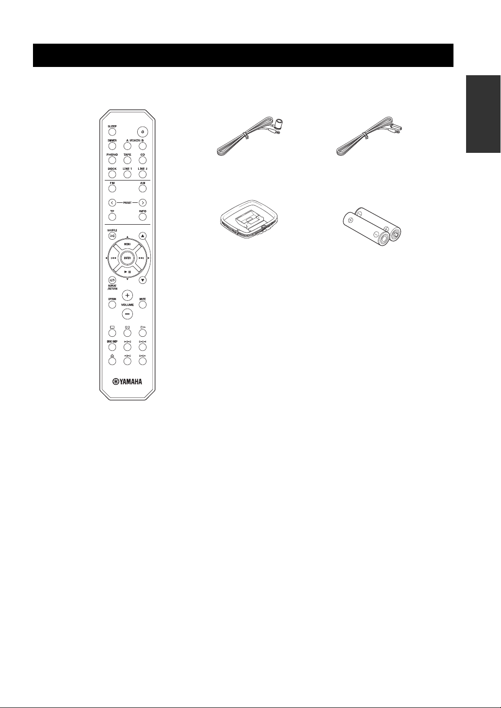
Please check that you received all of the following parts.
Remote control
Indoor FM antenna
AM loop antenna Batteries (x2)
(U.S.A. model)
INTRODUCTION
Indoor FM antenna
(Australia model)
(AA, R6, UM-3)
■ Notes on remote control and batteries
• Do not spill water or other liquids on the remote control.
• Do not drop the remote control.
• Do not leave or store the remote control in the following conditions:
– places of high humidity, such as near a bath
– places of high temperatures, such as near a heater or stove
– places of extremely low temperatures
– dusty places
• Use AA, R6, UM-3 batteries for the remote control.
• Insert batteries according to the polarity markings (+ and -).
• Change all batteries if you notice the operation range of the remote control narrows.
• If the batteries run out, immediately remove them from the remote control to prevent an explosion or acid leak.
• If you find leaking batteries, discard the batteries immediately, taking care not to touch the leaked material. If the leaked material
comes into contact with your skin or gets into your eyes or mouth, rinse it away immediately and consult a doctor. Clean the battery
compartment thoroughly before installing new batteries.
• Do not use old batteries together with new ones. This may shorten the life of the new batteries or cause old batteries to leak.
• Do not use different types of batteries (such as alkaline and manganese batteries) together. Batteries that look the same may have a
different specification.
• Before inserting new batteries, wipe the battery compartment clean.
• Dispose of batteries according to your regional regulations.
3 En
Page 8
CONTROLS AND FUNCTIONS
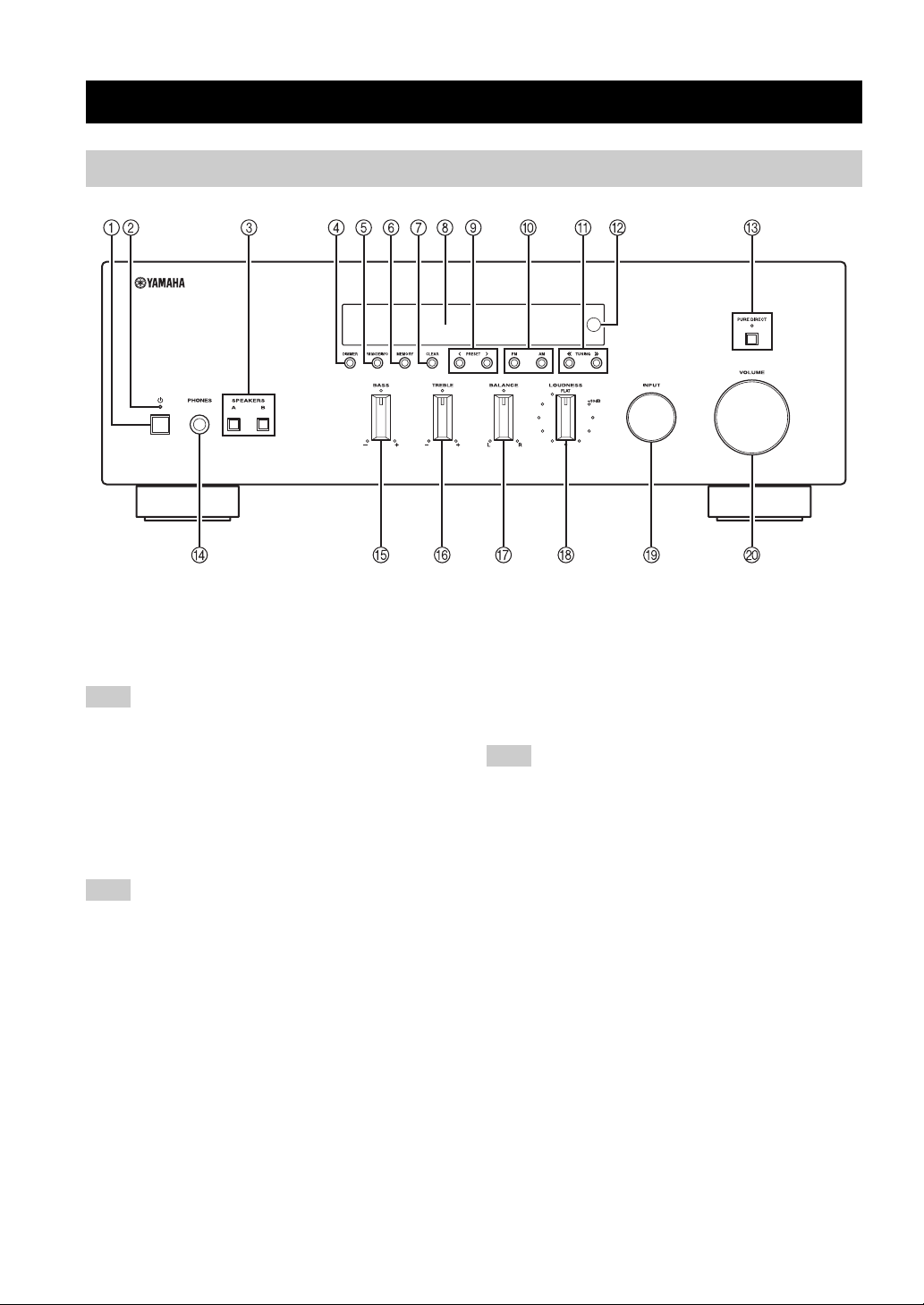
Front panel
CONTROLS AND FUNCTIONS
1 A (power)
Turns on and off the power of this unit (see page 14).
On position: Pushed inward
Off position: Released outward
Note
This unit consumes a small amount of power even when turned
off or when in standby mode.
2 Power indicator
Lights up as follows:
Brightly lit: Power is on
Dimly lit: Standby mode
Off: Power is off
Note
If an iPhone/iPod is charged while this unit is in standby mode,
the power indicator lights up brightly.
3 SPEAKERS A/B
Turns on or off the speaker set connected to the
SPEAKERS A and/or SPEAKERS B terminals on the rear
panel each time the corresponding button is pressed (see
page 14).
4 DIMMER
Changes the brightness level of the front panel display.
Choose brightness from 3 levels by pressing this button
repeatedly.
y
This setting is retained even if you turn off this unit.
5 FM MODE/INFO
Changes the FM radio wave reception mode (stereo or
monaural) when TUNER is selected as the input source
(see page 19).
Changes the playback information displayed about the
song playing on the iPhone/iPod when DOCK is selected
as the input source (see page 25).
Note
Playback information can only be displayed for an iPhone/iPod
that is connected using a Universal Dock for iPod.
6 MEMORY
Stores the current FM/AM station as a preset when
TUNER is selected as the input source (see page 21).
7 CLEAR
Clears the current FM/AM preset station when TUNER is
selected as the input source (see page 22).
8 Front panel display
Shows information about the operational status of this
unit.
9 PRESET j / i
Selects a preset FM/AM station when TUNER is selected
as the input source (see page 22).
0 FM, AM
Sets the FM/AM tuner band to FM or AM when TUNER
is selected as the input source (see page 18).
4 En
Page 9

A TUNING jj / ii
Selects the tuning frequency when TUNER is selected as
the input source (see page 18).
B Remote control sensor
Receives infrared signals from the remote control.
C PURE DIRECT and indicator
Allows you to listen to a source in the purest possible
sound (see page 15). The indicator above it lights up and
the front panel display turns off when this function is
turned on.
D PHONES jack
Outputs audio to your headphones for private listening.
Note
Press SPEAKER A/B so that the SP A/B indicators turn off
before you connect your headphones to the PHONES jack.
E BASS control
Increases or decreases the low frequency response. The
center position produces a flat response (see page 15).
F TREBLE control
Increases or decreases the high frequency response. The
center position produces a flat response (see page 15).
G BALANCE control
Adjusts the sound output balance of the left and right
speakers to compensate for sound imbalances caused by
speaker locations or listening room conditions (see page
15).
CONTROLS AND FUNCTIONS
INTRODUCTION
H LOUDNESS control
Retains a full tonal range at any volume level to
compensate for the human ears’ loss of sensitivity to high
and low-frequency ranges at a low volume level (see page
16).
I INPUT selector
Selects the input source you want to listen to.
J VOLUME control
Increases or decreases the sound output level.
Note
This does not affect the output level of the REC jacks.
5 En
Page 10

CONTROLS AND FUNCTIONS
Front panel display
1 SP (SPEAKERS) A/B indicators
Light up according to the set of speakers selected.
Both indicators light up when both sets of speakers are
selected.
2 Input source indicators
Light up brightly to indicate the input source that is
currently selected.
3 PRESET indicator
Lights up when you recall a preset radio station. Blinks
while the automatic station preset feature is scanning for
FM stations to register as presets.
4 MEMORY indicator
Lights up or blinks when an FM/AM station is being
stored as a preset.
5 TUNED indicator
Lights up when this unit is tuned in to an FM or AM
station.
6 STEREO indicator
Lights up when this unit is receiving a strong signal for an
FM stereo broadcast.
7 SLEEP indicator
Lights up when the sleep timer is turned on.
8 MUTE indicator
Blinks while the MUTE function is turned on.
9 P indicator
Lights up when a preset number is selected. Blinks while
you are registering a preset radio station.
0 Multi-information display
Shows information when adjusting or changing settings.
A Volume indicator
Displays the current volume level.
6 En
Page 11
Rear panel
CONTROLS AND FUNCTIONS
CONTROLS AND FUNCTIONS
INTRODUCTION
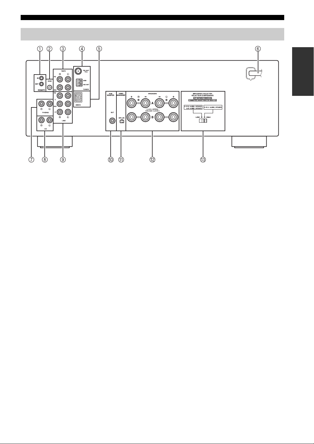
1 REMOTE IN/OUT jacks
Used to send and receive remote control signals (see page
13).
2 GND terminal
Used to connect a turntable (see page 10).
3 TAPE jacks
Used to connect a tape deck (see page 10).
4 Antenna terminals
Used to connect FM and AM antennas (see page 12).
5 DOCK jack
Used to connect an optional Yamaha Universal Dock for
iPod (such as the YDS-12), Wireless System for iPod
(YID-W10), or Bluetooth Wireless Audio Receiver
(YBA-10) (see page 24).
6 Power cable
For connecting this unit to an AC wall outlet (see page
13).
7 PHONO jacks
Used to connect a turntable (see page 10).
8 CD jacks
Used to connect a CD player (see page 10).
9 LINE 1-2 jacks
Used to connect audio components (see page 10).
A POWER MANAGEMENT switch
Used to enable or disable the automatic power down
function. When this function is enabled, this unit
automatically enters standby mode if it is not operated for
a certain amount of time (3 settings are available; see page
31).
B SPEAKERS terminals
Used to connect speakers (see page 10).
C IMPEDANCE SELECTOR switch
Used to select the impedance setting (see page 11).
0 SUBWOOFER OUT jack
Used to connect a subwoofer with built-in amplifier (see
page 10).
7 En
Page 12
CONTROLS AND FUNCTIONS
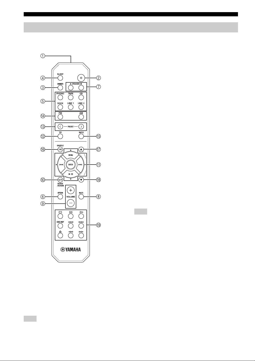
Remote control
This section describes the function of each button on the
remote control used to control this unit or a Yamaha CD
player.
3 DIMMER
Changes the brightness level of the front panel display.
Choose brightness from 3 levels by pressing this button
repeatedly.
y
This setting is retained even if you turn off this unit.
4 SLEEP
Sets the sleep timer (see page 17).
5 Input selector buttons
Select the input source you want to listen to.
y
• The input source names correspond to the names of the
connection jacks on the rear panel.
• To select TUNER as the input source using the remote control,
press FM or AM.
6 OPTION
Turns the OPTION menu on and off (see page 29).
7 SPEAKERS A/B
Turns on and off the set of speakers connected to the
SPEAKERS A and/or SPEAKERS B terminals on the rear
panel of this unit when the corresponding button is
pressed.
8 MUTE
Mutes the sound output. Press again to restore the sound
output to the previous volume level.
9 VOLUME +/–
Increases or decreases the sound output level.
■ Common controls
The following buttons can be used no matter which input
source is selected.
1 Infrared signal transmitter
Sends infrared signals.
2 A (power)
Turns this unit on, or sets it to standby mode.
Note
This button functions only when the A (power) button on the
front panel is in the on position.
8 En
Note
This does not affect the output level of the REC jacks.
0 RETURN
Returns to the previous menu or ends the menu display
when using the Option menu (see page 29).
A B / C / D / E / ENTER
Selects and confirms items in the Option menu (see page
29).
B TP
This button can be used for the Europe model only.
Page 13
CONTROLS AND FUNCTIONS
■ FM/AM controls
The following buttons can be used when TUNER is
selected as the input source.
C PRESET j / i
Selects a preset FM/AM station when TUNER is selected
as the input source (see page 22).
D FM, AM
Selects TUNER as the input source and sets the FM/AM
tuner band to FM or AM (see page 18).
■ iPod controls
The following buttons can be used when DOCK is
selected as the input source for listening to an iPhone/
iPod. For more information, see page 24.
0 REPEAT
A MENU/ Ee / b / a / ENTER
E INFO
F SHUFFLE
G B
H C
■ Yamaha CD player controls
The following buttons can be used to control a Yamaha
CD player when CD is selected as the input source.
I Yamaha CD player control buttons
• s Stops playback
• e Pauses playback
• p Starts playback
• DISC SKIP Skips to the next disc in a CD changer
• b Skips backward
• a Skips forward
• Ejects the disc
• w Rewinds playback
• f Fast-forwards playback
Note
Even when using a Yamaha CD player, certain components and
features may not be available. Refer to your component’s owner’s
manual for more information.
INTRODUCTION
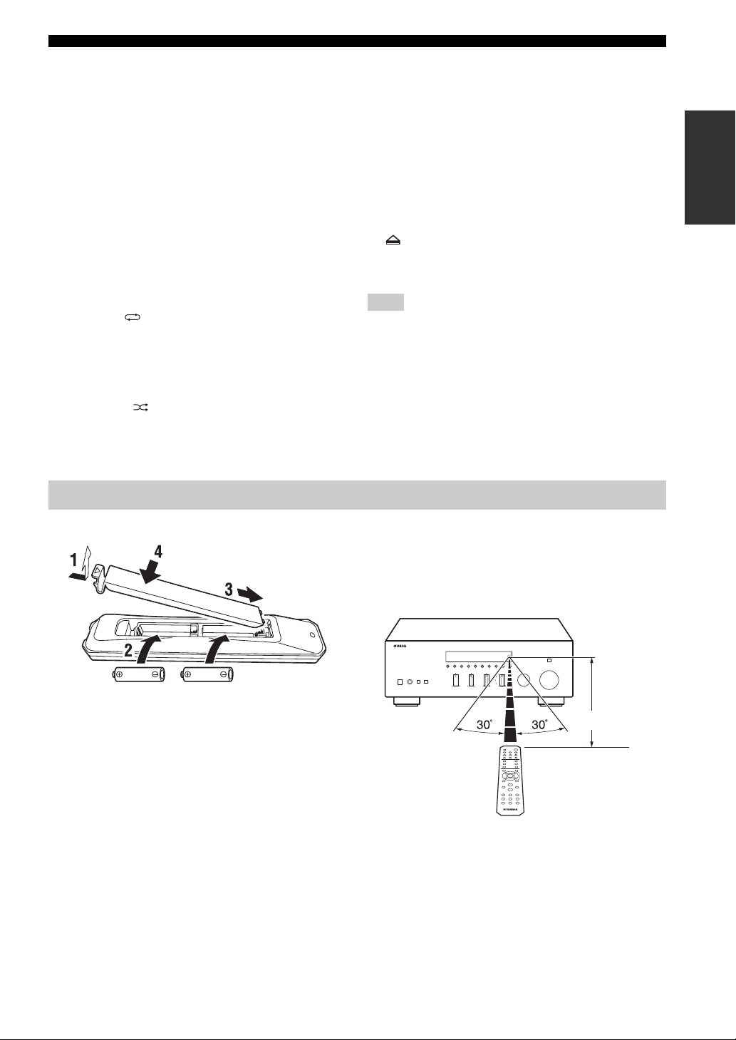
Using the remote control
■ Installing batteries ■ Operation range
The remote control transmits a directional infrared beam.
Be sure to aim the remote control directly at the remote
control sensor on the front panel of this unit during
operation.
AA, R6, UM-3 batteries
Approximately
6 m (20 ft)
Remote control
9 En
Page 14

CONNECTIONS
CONNECTIONS
Connecting speakers and source components
CAUTION
• Do not connect this unit or other components to the main power until all connections between components are
complete.
• All connections must be correct: L (left) to L, R (right) to R, “+” to “+” and “–” to “–”. If the connections are faulty,
no sound will be heard from the speakers, and if the polarity of the speaker connections is incorrect, the sound will be
unnatural and lack bass. Refer to the owner’s manual for each of your components.
• Use RCA cables for audio components (except for speaker connections and DOCK jack connections).
• The IMPEDANCE SELECTOR must be set to the appropriate position before connecting speakers. See page 11 for
details.
• Do not let bare speaker wires touch each other or any metal part of this unit. This could damage this unit and/or the
speakers.
Audio
out
Turntable
GND
Audio
out
Tape deck
For information about
other components that
can be connected to
this unit, see page 24.
Audio
in
Speakers A
Audio
out
CD player
Audio
out
DVD player,
etc.
Audio
in
CD recorder,
etc.
Audio
out
Subwoofer
Speakers B
y
• The PHONO jacks are designed for connecting a turntable with an MM cartridge.
• Connect your turntable to the GND terminal to reduce noise in the signal. However, for some turntables, you may hear less noise
without the GND connection.
10 En
Page 15

CONNECTIONS
■ IMPEDANCE SELECTOR switch
CAUTION
Do not change the IMPEDANCE SELECTOR switch
while the power of this unit is turned on, as doing so may
damage the unit.
If the unit fails to turn on, the IMPEDANCE SELECTOR
switch may not be fully slid to either position. If this is the
case, remove the power cable and slide the switch all the
way to either position.
Select the switch position (LOW or HIGH) according to
the impedance of the speakers in your system.
Switch
position
HIGH
LOW
• If you use one set (A or B), the impedance of
each speaker must be 8
• If you use two sets (A and B) simultaneously,
the impedance of each speaker must be 16
or higher. (Except for U.S.A. model)
• If you make bi-wire connections, the
impedance of each speaker must be 8
higher. See page 11 for Bi-wire connection.
• If you use one set (A or B), the impedance of
each speaker must be 4
• If you use two sets (A and B) simultaneously,
the impedance of each speaker must be 8
higher.
• If you make bi-wire connections, the
impedance of each speaker must be 4
higher. See page 11 for Bi-wire connection.
Impedance level
Ω or higher.
Ω
Ω or
Ω or higher.
Ω or
Ω or
■ Connecting speaker cables
■ Bi-wire connection
Bi-wire connection separates the woofer from the
combined midrange and tweeter section. A bi-wire
compatible speaker has four binding post terminals. These
two sets of terminals allow the speaker to be split into two
independent sections. With these connections, the mid and
high frequency drivers are connected to one set of
terminals and the low frequency driver to another set of
terminals.
This unit
Speaker
Connect the other speaker to the other set of terminals in
the same way.
CAUTION
When making bi-wire connections, set the IMPEDANCE
SELECTOR switch to HIGH or LOW depending on the
impedance of your speakers:
8 Ω or higher: HIGH
4 Ω or higher: LOW
See page 11 for more information about the
IMPEDANCE SELECTOR switch.
PREPARATION
Remove
approximately
10 mm (3/8 in)
of insulation
from the end of
each speaker
cable.
Note
When inserting speaker cables into the speaker terminals, insert
only the bare speaker wire. If insulated cable is inserted, the
connection may be poor and sound may not be heard.
■ Connecting via banana plug
Tighten the knob and then insert the banana plug into the
end of the corresponding terminal.
Banana plug
Note
When making bi-wire connections, remove the shorting bridges
or cables on the speaker.
y
To use the bi-wire connections, press SPEAKERS A and
SPEAKERS B on the front panel or on the remote control so that
both SP A and B light up on the front panel display.
SPEAKERS A/B
SPEAKERS A/B
11 En
Page 16

CONNECTIONS
Connecting the FM and AM antennas
Indoor antennas for receiving FM and AM broadcasts are included with this unit. In general, these antennas should
provide sufficient signal strength. Connect each antenna correctly to the designated terminals.
Note
If you experience poor reception quality, install an outdoor antenna. Consult the nearest authorized Yamaha dealer or service center
about outdoor antennas.
Outdoor AM antenna
Use 5 to 10 m of vinylcovered wire extended
outdoors from a window.
Indoor FM
antenna
(included)
Outdoor FM antenna
AM loop antenna
(included)
• The AM loop antenna
should always be connected,
even if an outdoor AM
antenna is connected to this
unit.
• The AM loop antenna
should be placed away from
this unit.
Ground (GND terminal)
For maximum safety and minimum interference, connect
the antenna GND terminal to a good earth ground. A
good earth ground is a metal stake driven into moist earth.
■ Assembling the supplied AM loop
antenna
■ Connecting the wire of the AM loop
antenna
12 En
Page 17

CONNECTIONS
Connecting an infrared signal receiver or Yamaha component to the REMOTE IN/OUT jacks
An infrared signal receiver can be connected to the
REMOTE IN jack using a monaural 3.5 mm mini plug
cable as follows. In addition, Yamaha components that are
capable of transmitting and receiving remote control
signals can be connected to the REMOTE IN and
REMOTE OUT jacks.
Remote
control out
Infrared signal
receiver or Yamaha
component
Yamaha component
(CD or DVD player, etc.)
Remote
control in
Connecting power cable
Plug the power cable into the AC wall outlet after all other
connections are complete.
To the wall
outlet with the
power cable
PREPARATION
• By connecting the remote control output jack of an
infrared signal receiver to the REMOTE IN jack, you
can control this unit using the remote control even if
this unit is placed in a rack or other location where the
remote control signals cannot reach.
• By connecting the remote control input jack of another
Yamaha component to the REMOTE OUT jack, you
can control the component using the remote control of
this unit or the Yamaha component.
y
Up to six Yamaha components can be connected in series using
the remote control input and output jacks.
13 En
Page 18

PLAYING AND RECORDING
PLAYING AND RECORDING
CAUTION
Extreme caution should be exercised when you play back CDs encoded in DTS.
If you play back a CD encoded in DTS on a CD player that does not support DTS, only noise will be heard, and this noise
may damage your speakers. Check whether your CD player supports CDs encoded in DTS. Also, check the sound output
level of your CD player before you play back a CD encoded in DTS.
Playing a source
SPEAKERS A/B INPUT selector
A (power)
VOLUME
A (power)
SPEAKERS A/B
Input selector
buttons
FM, AM
VOLUME +/–
3 Press SPEAKERS A and/or SPEAKERS B on
the front panel or on the remote control to
select speakers A and/or speakers B.
When speaker set A or speaker set B are turned on,
SP A or SP B is displayed on the front panel display
accordingly (see page 6).
Notes
• When one set of speakers is connected using bi-wire
connections, or when using two sets of speakers simultaneously
(A and B), make sure SP A and SP B are displayed on the front
panel display.
• When listening with headphones, turn off the speakers.
4 Play the source.
5 Rotate the VOLUME control on the front
panel (or press VOLUME +/– on the remote
control) to adjust the sound output level.
y
You can adjust the tonal quality by using the BASS, TREBLE,
BALANCE and LOUDNESS controls, or the PURE DIRECT
switch on the front panel (see page 15).
6 When finished listening, press A (power) on
the front panel outward to turn off this unit.
y
If A (power) on the remote control is pressed while the A (power)
button on the front panel is in the on position, this unit enters
standby mode. Press A (power) again to turn this unit on.
1 Press A (power) on the front panel inward to
turn on this unit.
2 Rotate the INPUT selector on the front panel
(or press one of the input selector buttons or
FM or AM on the remote control) to select the
input source you want to listen to.
14 En
Page 19

Adjusting the tonal quality
■ Using the PURE DIRECT switch
Routes input signals from your audio sources so that the
input signals bypass the BASS, TREBLE, BALANCE and
LOUDNESS controls, thus eliminating any alterations to
the audio signals and creating the purest possible sound.
The PURE DIRECT indicator lights up and the front panel
display turns off after a few seconds.
PURE DIRECT switch
Notes
• The BASS, TREBLE, BALANCE, and LOUDNESS controls
do not function while the PURE DIRECT feature is turned on.
• This setting is retained even if you turn off this unit.
PLAYING AND RECORDING
■ Adjusting the BASS and TREBLE
controls
TREBLE
BASS
The BASS and TREBLE controls adjust high and low
frequency response.
The center position produces a flat response.
BASS
When you feel there is not enough bass (low frequency
sound), rotate clockwise to boost. When you feel there is
too much bass, rotate counterclockwise to suppress.
Control range: –10 dB to +10 dB (20 Hz)
TREBLE
When you feel there is not enough treble (high frequency
sound), rotate clockwise to boost. When you feel there is
too much treble, rotate counterclockwise to suppress.
Control range: –10 dB to +10 dB (20 kHz)
OPERATION
BASIC
■ Adjusting the BALANCE control
BALANCE
The BALANCE control adjusts the sound output balance
of the left and right speakers to compensate for sound
imbalance caused by speaker locations or listening room
conditions.
15 En
Page 20

PLAYING AND RECORDING
■ Adjusting the LOUDNESS control
LOUDNESS VOLUME
VOLUME +/–
3 Rotate the LOUDNESS control until the
desired volume is obtained.
y
After setting the LOUDNESS control, enjoy listening to music at
your preferred volume level. If the effect of the LOUDNESS
control setting is too strong or weak, readjust the LOUDNESS
control.
Retain a full tonal range at any volume level, thus
compensating for the human ears’ loss of sensitivity to
high and low-frequency ranges at low volume.
CAUTION
If the PURE DIRECT switch is turned on with the
LOUDNESS control set at a certain level, the input signals
bypass the LOUDNESS control, resulting in a sudden
increase in the sound output level. To prevent your ears or
the speakers from being damaged, be sure to press the
PURE DIRECT switch after lowering the sound output
level or after checking that the LOUDNESS control is
properly set.
1 Set the LOUDNESS control to the FLAT
position.
2 Rotate the VOLUME control on the front
panel (or press VOLUME +/– on the remote
control) to set the sound output level to the
loudest listening level that you would listen
to.
16 En
Page 21

PLAYING AND RECORDING
Recording a source
Notes
• The audio from the current input source is output to the TAPE
REC and LINE 1 REC jacks. When TAPE is selected, audio is
output to the LINE 1 REC jacks only. When LINE 1 is selected,
audio is output to the TAPE REC jacks only.
• This unit must be turned on in order to record.
• The VOLUME, BASS, TREBLE, BALANCE and
LOUDNESS controls and the PURE DIRECT switch have no
effect on the source being recorded.
• Check the copyright laws in your country before recording from
records, CDs, radio, etc. Recording copyright-protected
material may infringe on copyright laws.
INPUT selector
Using the sleep timer
Use this feature to automatically set this unit to standby
mode after a certain amount of time. The sleep timer is
useful when you are going to sleep while this unit is
playing or recording a source.
A (power)
SLEEP
Note
The sleep timer can only be set with the remote control.
A (power)
OPERATION
BASIC
Input selector
buttons
FM, AM
1 Rotate the INPUT selector on the front panel
(or press one of the input selector buttons or
FM or AM on the remote control) to select the
source you want to record.
2 Play the source and begin recording using
the recording device connected to the REC
jacks (TAPE and/or LINE 1) on the rear panel.
See page 10.
1 Press SLEEP repeatedly to set the amount of
time before this unit is set to standby mode.
Each time you press SLEEP, the front panel display
changes as shown below.
The SLEEP indicator blinks while setting the amount
of time for the sleep timer.
If the sleep timer is set, the SLEEP indicator on the
front panel display lights up.
y
To cancel the sleep timer, do one of the following:
• Select “Sleep Off”.
• Press A (power) on the remote control to set this unit to standby
mode.
• Press A (power) on the front panel to turn off this unit.
17 En
Page 22

FM/AM TUNING
FM/AM TUNING
There are 2 tuning methods; automatic and manual. Select either method according to your preference and the strength of
station signals.
Automatic tuning
Automatic tuning is effective when station signals are
strong and there is no interference.
INPUT selector
TUNING jj / ii
FM, AM
FM, AM
3 Press and hold TUNING jj / ii on the front
panel for more than 1 second to begin
automatic tuning.
Press ii to tune in to a higher frequency.
Press jj to tune in to a lower frequency.
Notes
• When you tune in to a station, the frequency of the station is
displayed on the front panel display.
• If the tuning search does not stop at the desired station because
the station signals are weak, try using the manual tuning
method.
■ Auto Mute feature
When listening to an FM radio station, the output will
automatically be muted when the radio signal is weak if
the station was tuned in to by:
• using the automatic tuning feature
• recalling a preset that was registered using the
automatic preset registration feature
If you want to listen to a station that has a weak signal,
tune in to the station manually.
1 Rotate the INPUT selector on the front panel
(or press FM or AM on the remote control) to
select TUNER as the input source.
Note
If you press FM or AM on the remote control to select TUNER as
the input source, the corresponding band is also selected,
therefore you may skip step 2.
2 Press FM or AM on the front panel (or FM or
AM on the remote control) to select the
reception band (FM or AM).
FM or AM is displayed on the front panel display.
18 En
Page 23

Manual tuning
Manual tuning is effective when station signals are weak.
FM/AM TUNING
■ Improving FM reception
If the signal from the station is weak and the sound quality
is not good, set the FM band reception mode to monaural
mode to improve reception.
INPUT selector
TUNING jj / ii
FM, AM
FM, AM
1 Rotate the INPUT selector on the front panel
(or press FM or AM on the remote control) to
select TUNER as the input source.
Note
If you press FM or AM on the remote control to select TUNER as
the input source, the corresponding band is also selected,
therefore you may skip step 2.
FM MODE/INFO
1 Press FM MODE/INFO on the front panel
repeatedly to select “STEREO” (automatic
stereo mode) or “MONO” (monaural mode)
when this unit is tuned in to an FM radio
station.
• When MONO is selected, FM broadcasts will be
heard in monaural sound.
• When STEREO is selected and an FM station with
a stereo broadcast is tuned in, the broadcast will be
heard in stereo.
Note
The STEREO indicator on the front panel lights up while
listening to a station in stereo.
y
The FM band reception mode (monaural or stereo) can also be
changed by selecting FM Mode in the Option menu (see page 29).
OPERATION
BASIC
2 Press FM or AM on the front panel (or FM or
AM on the remote control) to select the
reception band (FM or AM).
FM or AM is displayed on the front panel display.
3 Press TUNING jj / ii on the front panel to
manually tune in to the desired station.
Note
When you tune in to a station, the frequency of the received
station is shown in the front panel display.
19 En
Page 24

FM/AM TUNING
Automatic station preset (FM stations only)
You can use the automatic station preset function to
automatically register FM stations as presets. This
function enables this unit to automatically tune in to FM
stations that have a strong signal and store up to 40 of
those stations in order. You can then easily recall any
preset station by selecting its preset number.
Notes
• If a station is registered to a preset number that already has a
station registered to it, the previously registered station is
overwritten.
• If the station you want to store is weak in signal strength, try
using the manual preset tuning method.
y
FM stations registered as presets using the automatic preset
registration feature will be heard in stereo.
2 Press FM on the front panel (or FM on the
remote control) to select FM as the reception
band.
FM is displayed on the front panel display.
3 Press OPTION on the remote control.
The Option menu for TUNER is displayed (see page
29).
4 Press B / C on the remote control to select
“Auto Preset”, and then press ENTER.
This unit starts scanning the FM band about 5
seconds later from the lowest frequency upwards.
y
• Before scanning begins, you can specify the first preset number
to be used by pressing PRESET j / i on the front panel (or
PRESET j / i or B/C on the remote control).
• To cancel scanning, press FM or AM on the front panel (or FM
or AM or RETURN on the remote control).
FM
PRESET j / i
B / C
ENTER
RETURN
OPTION
INPUT selector
FM
PRESET j / i
1 Rotate the INPUT selector on the front panel
(or press FM on the remote control) to select
TUNER as the input source.
Note
If you press FM on the remote control to select TUNER as the
input source, the corresponding band is also selected, therefore
you may skip step 2.
Preset number Frequency
(Australia model)
When presets are registered, information is displayed
on the front panel display as shown in the illustration
above.
When scanning is complete, “FINISH” is displayed
and then the display returns to the Option menu.
To return the display to the original state, press
OPTION or RETURN on the remote control.
20 En
Page 25

FM/AM TUNING
Manual station preset
You can manually register up to 40 FM/AM stations (40
total). You can then easily recall any preset station by
selecting its preset number.
PRESET j / i
MEMORY
PRESET j / i
RETURN
1 Tune in to the desired FM/AM station.
See pages 18 and 19 for tuning instructions.
2 Press MEMORY on the front panel.
“MANUAL PRESET” is displayed briefly on the
front panel display, and then the preset number to
which the station will be registered is displayed.
y
By holding down MEMORY on the front panel for more than 2
seconds, you can skip the following steps and automatically
register the selected station to an empty preset number (i.e., the
preset number following the last preset number used).
3 Press PRESET j / i on the front panel (or
PRESET j / i on the remote control) to select
the preset number to which the station will
be registered.
When you select a preset number to which no station
is registered, “EMPTY” is displayed. When you
select a preset number to which a station has already
been registered, the frequency of the station is
displayed.
OPERATION
BASIC
Preset number
4 Press MEMORY on the front panel.
When registration is complete, the display returns to
the original state.
y
To cancel registration, RETURN on the remote control or do not
perform any operations for about 30 seconds.
21 En
Page 26

FM/AM TUNING
Recalling a preset station
You can recall preset stations that were registered using
automatic station preset or manual station preset.
PRESET j / i
PRESET j / i
Clearing a preset station
Follow the steps below to clear a preset station.
CLEAR
RETURN
1 Select the desired preset station number.
See “Recalling a preset station” on page 22.
1 Press PRESET j / i on the front panel (or
PRESET j / i on the remote control) to select
a preset number.
y
• Preset numbers to which no stations are registered are skipped.
• “NO PRESETS” is displayed if no stations are registered.
2 Press CLEAR on the front panel.
The selected preset number flashes on the front panel
display.
(Australia model)
y
To cancel clearing the preset station, press RETURN on the
remote control or leave this unit without any operations for about
30 seconds.
3 Press CLEAR on the front panel to confirm.
“PXX: CLEARED” (XX indicates the preset
number) is displayed on the front panel display, and
then the display returns to its original state.
22 En
Page 27

FM/AM TUNING
Clearing all preset stations
Follow the steps below to clear all preset stations.
INPUT selector
FM, AM
B / C / D / E
ENTER
RETURN
4 Press D / E on the remote control to select
“YES”, and then press ENTER.
y
To cancel without clearing the presets, select “NO”.
When all presets have been cleared, “PRESET
CLEARED” is displayed, and then the display returns
to the Option menu.
5 To exit the Option menu, press OPTION or
RETURN on the remote control.
OPERATION
BASIC
OPTION
1 Rotate the INPUT selector on the front panel
(or press FM or AM on the remote control) to
select TUNER as the input source.
2 Press OPTION on the remote control.
The Option menu for TUNER is displayed (see
page 29).
3 Press B / C on the remote control to select
“Clr All Preset”, and then press ENTER.
y
To cancel the operation and return to the Option menu, press
RETURN on the remote control.
23 En
Page 28

PLAYING BACK TUNES FROM YOUR IPHONE/IPOD/BLUETOOTH™ COMPONENT
PLAYING BACK TUNES FROM YOUR iPhone/iPod/
Bluetooth™ COMPONENT
Once you have connected an optional Yamaha Universal Dock for iPod (such as the YDS-12), Wireless System for iPod
(YID-W10), or Bluetooth Wireless Audio Receiver (YBA-10) to the DOCK jack on the rear panel of this unit, you can
enjoy playback of your iPhone/iPod or Bluetooth component using the remote control supplied with this unit.
Model
(As of July 2010)
Operated by
Supported iPhone/iPod
(As of July 2010)
Remarks
Such as the
YDS-12
Universal Dock for iPod Wireless System for iPod
•YDS-12
•YDS-11
•YDS-10
• Remote control
• iPhone/iPod connected to the
dock
• iPod touch
•iPod (4th Gen/
5th Gen/
classic)
• iPod nano
• iPhone/iPod charging also
supported.
• The YDS-10/YDS-11 does not
support iPhone connection.
•iPod mini
•iPhone
•iPhone 3G
•iPhone 3GS
YID-W10 YBA-10
• iPhone/iPod connected to the
YID-W10 transmitter
• Remote control
•iPod touch
•iPod (5th Gen/
classic)
• iPod nano
iPhone/iPod charging also
supported.
• iPhone
• iPhone 3G
• iPhone 3GS
YID-W10 YBA-10
Position the connected
device as far as possible
from the unit.
Bluetooth Wireless Audio
Bluetooth components
Receiver
CAUTION
To prevent accidents, unplug the power cable of this unit before connecting a Universal Dock for iPod, a Wireless
System for iPod or a Bluetooth Wireless Audio Receiver.
Note
If the iPhone connected to the YID-W10 receives a call while this unit is in standby mode, the unit turns on automatically and the
ringtone is heard through this unit. If you do not want this unit to turn on when a call is received, set the iPhone to silent mode.
24 En
Page 29

PLAYING BACK TUNES FROM YOUR iPhone/iPod/Bluetooth™ COMPONENT
Using a Universal Dock for iPod
■ Controlling your iPhone/iPod
After setting your iPhone/iPod in your dock, rotate the INPUT selector on the front panel (or press DOCK on the remote
control) to select DOCK as the input source to play your iPhone/iPod.
DOCK
INFO
B
MENU/ Ee / b / a
ENTER
OPERATION
BASIC
C
While viewing the information displayed on your iPhone/iPod, use the following remote control buttons to operate
(playback, pause, skip, etc.) your iPhone/iPod.
Remote control Operation
MENU
ENTER
B
C
Ee
a
b
INFO
Displays the menu.
• If an item is selected: Confirms the item and displays the next screen.
• If a song is selected: Plays the selected song.
Scroll up.
Scroll down.
• If a song is playing: Pauses the song.
• If a song is paused: Plays the song.
• If a song is playing or paused: Skips to the beginning of the next song.
• If pressed and held: Searches forward.
• If a song is playing or paused: Skips to the beginning of the current song.
• Pressing repeatedly skips one song backwards with each press.
• If pressed and held: Searches backward.
Switches between shuffle modes (Off → Songs → Albums → Off).
Switches between repeat modes (Off → One → All → Off).
Switches between items displayed on the front panel display of this unit (Song number and elapsed
time → Songs → Artists → Albums → Song number and elapsed time).
Note
Some shuffle modes and repeat modes may not be available depending on the model or the software version of your iPhone/iPod.
y
When this unit is turned on or is in standby mode, your iPhone/iPod can be charged automatically if it is connected to a Universal Dock
for iPod. If an iPhone/iPod is charged while this unit is in standby mode, the power indicator lights up brightly.
25 En
Page 30

PLAYING BACK TUNES FROM YOUR iPhone/iPod/Bluetooth™ COMPONENT
■ Controlling this unit with your iPhone/
Using a Wireless System for iPod
By connecting a Wireless System for iPod to this unit, you
can play songs on your iPhone/iPod and listen to them
using a wireless connection.
y
You can use the remote control to control the iPhone/iPod. For
more information, see page 25.
Note
When playing an iPhone/iPod using a Wireless System for iPod,
playback information is not displayed on the front panel display.
YID-W10
transmitter
■ Establishing a wireless connection
Once the iPhone/iPod is connected to the YID-W10
transmitter and playback begins, it takes about 5 seconds
for audio to be heard. During this time the wireless
connection between the YID-W10 transmitter and
receiver is established.
The status of the wireless connection between the YIDW10 transmitter and receiver is indicated by the
respective indicator.
Status of
Connection
No connection Off Off
Confirming
connection
Connected Green, lit Blue, lit
YID-W10
transmitter
indicator
Green, flashing Blue, flashing
YID-W10 receiver
YID-W10
receiver
indicator
iPod
• When playback begins on an iPhone/iPod that is
connected to a YID-W10 transmitter, and if the YIDW10 transmitter is within range of the YID-W10
receiver, this unit performs as follows:
– If this unit is already turned on when playback
– If this unit is in standby mode when playback
• In the following situations, the wireless connection
between the transmitter and receiver is disconnected.
After 30 seconds this unit automatically enters standby
mode.
– The iPhone/iPod is not operated for about 30–120
– The sleep timer of the iPhone/iPod is activated.
– The iPhone/iPod is disconnected from the YID-
– The iPhone/iPod battery level decreases to a level
– The YID-W10 transmitter is moved outside of the
– Communication between the YID-W10 transmitter
y
These features can be disabled by setting “Interlock” to “OFF” in
the Option menu (see page 30).
• Adjusting the volume on the iPhone/iPod also adjusts
the volume of this unit. The iPhone/iPod can increase
the volume to up to 0 dB (or the value set for the
“MaxVol” setting in the Option menu). To further
increase the volume, adjust the volume using this unit’s
VOLUME control or the remote control.
y
• When this unit is turned on or is in standby mode, your iPhone/
iPod can be charged automatically if the YID-W10 transmitter
connected to your iPhone/iPod is stationed in the YID-W10
receiver. If an iPhone/iPod is charged while this unit is in
standby mode, the power indicator lights up brightly.
• Refer to the operating instructions of the YID-W10 for more
information.
begins: The input source switches to DOCK.
begins: This unit turns on and the input source
switches to DOCK.
seconds after the playback is paused.
W10 transmitter.
where it cannot provide enough power to the YIDW10 transmitter.
wireless communication range of the YID-W10
receiver.
and receiver becomes disrupted due to interference
from other wireless LAN devices, cordless
telephones, microwave ovens, etc.
26 En
Page 31

PLAYING BACK TUNES FROM YOUR iPhone/iPod/Bluetooth™ COMPONENT
Using a Bluetooth Wireless Audio Receiver
Note
This unit supports A2DP (Advanced Audio Distribution Profile)
and AVRCP (Audio and Video Remote Control Profile) of the
Bluetooth profile.
■ Pairing Bluetooth™ components
MEMORY
DOCK
INPUT selector
1 Rotate the INPUT selector on the front panel
(or press DOCK on the remote control) to
select DOCK as the input source.
2 Turn on the Bluetooth component you want
to pair and set it to pairing mode.
3 Press OPTION on the remote control.
The Option menu for DOCK displayed (see page 29).
4 Press B / C on the remote control to select
“Pairing”, and then press ENTER.
“Searching...” is displayed and pairing begins.
y
To cancel pairing, press RETURN on the remote control.
5 Make sure the Bluetooth component
recognizes the Bluetooth Wireless Audio
Receiver.
When the component is recognized, it will be
displayed in the Bluetooth component list, for
example as “YBA-10 YAMAHA”.
OPERATION
BASIC
B / C
ENTER
RETURN
OPTION
Be sure to pair the Bluetooth Wireless Audio Receiver and
the Bluetooth component when connecting for the first
time or when settings have been deleted.
Refer to the operating instructions of your Bluetooth
component as necessary when carrying out pairing.
Note
The Bluetooth Wireless Audio Receiver can be paired with up to
eight Bluetooth components. When the ninth device is paired, the
pairing settings for the device which has not been used for the
longest period of time will be deleted.
6 Select the Bluetooth Wireless Audio
Receiver from the Bluetooth component list,
and enter a pass key “0000” using the
Bluetooth component.
When pairing is complete, “Completed” is displayed
on the front panel display.
To exit the Option menu, press OPTION on the
remote control.
y
When the input source is set to DOCK, you can also begin pairing
by pressing and holding MEMORY on the front panel (or
ENTER on the remote control).
27 En
Page 32

PLAYING BACK TUNES FROM YOUR iPhone/iPod/Bluetooth™ COMPONENT
■ Playing back BluetoothTM components
3 Press B / C on the remote control to select
“Connect”, and then press ENTER.
When wireless connection is complete, “Connected”
is displayed on the front panel display.
To exit the Option menu, press OPTION on the
remote control.
MEMORY
DOCK
B / C
ENTER
OPTION
INPUT selector
When pairing is complete, carry out the following
procedure to achieve a wireless connection between this
unit and the Bluetooth component.
When the wireless connection is complete, you can enjoy
playback from Bluetooth components.
Note
“Not found” is displayed if there is a connection error. Check that
the following conditions have been satisfied, and try to establish a
wireless connection again.
• Both this unit and the Bluetooth component are paired.
• The Bluetooth component is switched on.
• The Bluetooth component is within 32 feet/10 meters of the
Bluetooth wireless audio receiver.
4 Operate the Bluetooth component for
playback.
While the Bluetooth component is playing,
“BLUETOOTH” is displayed on the front panel
display.
Note
To disconnect a wireless connection, repeat these steps and select
“Disconnect” in step 3.
y
When the input source is set to DOCK, you can also establish a
wireless connection by pressing MEMORY on the front panel (or
ENTER on the remote control).
Note
Depending on the Bluetooth component, a wireless connection is
established automatically or when the Bluetooth component is
operated. In these cases, it is not necessary to carry out the
following procedure.
1 Rotate the INPUT selector on the front panel
(or press DOCK on the remote control) to
select DOCK as the input source.
2 Press OPTION on the remote control.
The Option menu for DOCK displayed (see page 29).
28 En
Page 33

SETTING THE OPTION MENU FOR EACH INPUT SOURCE
SETTING THE OPTION MENU FOR EACH INPUT SOURCE
The Option menu allows you to configure various settings for each input source and recall those settings automatically
when an input source is selected. Also, you can view the signal information for certain input sources.
The procedure for setting the Option menu items is described below.
3 Press B / C on the remote control to select
the desired menu item, and then press
ENTER.
4 Press B / C / D / E on the remote control to
change the settings.
INPUT selector
Input selector
buttons
FM, AM
y
For certain menu items, you must press ENTER to save the new
setting.
5 To exit the Option menu, press OPTION on
the remote control.
To return to the previous menu, press RETURN on
the remote control.
Note
If B / C / D / E on the remote control or other buttons do not
work after closing the Option menu, rotate the INPUT selector on
the front panel (or press one of the input selector buttons or FM or
AM on the remote control) to select the current input source
again.
OPERATION
ADVANCED
B / C / D / E
ENTER
RETURN
OPTION
1 Rotate the INPUT selector on the front panel
(or press one of the input selector buttons or
FM or AM on the remote control) to select the
desired input source.
2 Press OPTION on the remote control.
Note
If the input source is changed while the Option menu is displayed,
the front panel display exits the Option menu and the display for
the selected input source is displayed.
Option menu items
The following menu items are provided for each input
source.
Input source Menu items
PHONO, CD, TAPE 1,
LINE 1-2
TUNER (FM/AM) Volume, FM Mode, Auto Preset, Clr
DOCK (iPhone/iPod) Volume, Interlock*
DOCK (Bluetooth)
Note
*
“Interlock” is displayed in the Option menu only when using a
Wireless System for iPod.
Vo l u m e
All Preset
Volume, Connect, Disconnect,
Pairing
29 En
Page 34

SETTING THE OPTION MENU FOR EACH INPUT SOURCE
Details of the menu items are as follows. The
configuration will be reflected to the input source
currently selected.
y
The default settings are marked with “*”.
Vol um e
Submenus: MaxVol, IniVol
Adjustable range
(MaxVol):
Adjustable range
(IniVol): Off*, Mute, –89.5dB to +16.5dB (0.5 dB step)
.
–30.0dB to +15.0dB, +16.5dB* (5.0 dB step)
Sets items for volumes.
MaxVol (Maximum volume)
Sets the maximum volume level so that the volume will not
be accidentally increased above a certain level. For
example, you can adjust the volume between –89.5 dB and
–5.0 dB (or Mute) when you set this parameter to “–5.0dB”.
The volume can be increased to the maximum level when
this parameter is set to +16.5 dB (default).
IniVol (Initial volume)
Sets the volume at the time this unit is turned on. When
this parameter is set to “Off”, the volume level used when
this unit was set to standby is applied.
Note
If “MaxVol” is set to a value lower than the “IniVol” setting, the
setting for “MaxVol” overrides the “IniVol” setting. For
example, if you set “MaxVol” to “–30.0dB” and “IniVol” to
“0.0dB”, the volume is automatically set to “–30.0dB” the next
time this unit is turned on.
FM Mode
Choices: STEREO*, MONO
Sets the FM broadcast receiving mode.
“FM Mode” is displayed in the Option menu only when
TUNER is selected as the input source.
STEREO Receives in automatic stereo mode by priority.
MONO Receives in monaural mode. You can get a
better reception in monaural mode.
Interlock
Choices: ON*, OFF
When an iPhone/iPod is connected to this unit wirelessly
using a Wireless System for iPod, the iPhone/iPod can be
used to turn this unit on, set it to standby mode or select
DOCK as the input source.
“Interlock” is displayed in the Option menu only when
using a Wireless System for iPod and DOCK is selected as
the input source.
ON This unit responds to certain iPhone/iPod
operations.
OFF Disables this feature.
Connect/Disconnect
Connects to or disconnects from a Bluetooth component
(see page 28).
“Connect/Disconnect” is displayed in the Option menu
only when DOCK (Bluetooth) is selected as the input
source.
Pairing
Pairs the Bluetooth Wireless Audio Receiver and a
Bluetooth component (see page 27).
“Pairing” is displayed in the Option menu only when
DOCK (Bluetooth) is selected as the input source.
Auto Preset
Automatically detects FM radio stations and registers
them as preset stations (see page 20).
“Auto Preset” is displayed in the Option menu only when
TUNER is selected as the input source.
Clr All Preset
Clears all preset stations (see page 23).
“Clr All Preset” is displayed in the Option menu only
when TUNER is selected as the input source.
30 En
Page 35

ADVANCED SETUP
■ ADVANCED SETUP menu parameters
Change the initial settings to reflect the needs of your
listening environment.
y
The default settings are marked with “*”.
APD (Automatic Power Down) TIMER
Choices: 4H (4 hours), 8H* (8 hours), 12H (12 hours)
When the POWER MANAGEMENT switch on the rear
panel of this unit (see page 7) is set to ON, this unit
automatically enters standby mode if it is not operated for
the specified amount of time.
Note
When the POWER MANAGEMENT switch is set to OFF, “APD
TIMER -OFF” is displayed.
INITIALIZE
Choices: NO*, YES
Resets all parameters to their factory presets.
• Select NO to cancel without resetting all parameters to
their factory presets.
• Select YES to reset all parameters to their factory
presets.
Note
If “YES” is selected the parameters are reset the next time you
turn on the power of this unit.
ADVANCED SETUP
Changing the ADVANCED SETUP menu parameters
The ADVANCED SETUP menu is displayed in the front
panel display.
y
• Audio output is muted while setting parameters in the
ADVANCED SETUP menu.
• While setting parameters in the ADVANCED SETUP menu,
most controls on the front panel are disabled; only A (power),
the INPUT selector and FM MODE/INFO are operational.
A (power) FM MODE/INFO INPUT selector
1 Press and hold FM MODE/INFO on the front
panel, and then press A (power) inward.
This unit turns on, and the ADVANCED SETUP
menu is displayed on the front panel display.
OPERATION
ADVANCED
2 Rotate the INPUT selector on the front panel
to select the parameter you want to change.
See “ADVANCED SETUP menu parameters” on
page 31 for a complete list of available parameters.
3 Press FM MODE/INFO on the front panel
repeatedly to change the selected parameter
setting.
To change other settings, repeat steps 2 and 3.
4 Press A (power) on the front panel outward
to turn off this unit to confirm your setting.
Note
The settings you made take effect the next time you turn on this
unit.
31 En
Page 36

TROUBLESHOOTING
TROUBLESHOOTING
Refer to the chart below if this unit does not function properly. If the problem you are experiencing is not listed below or
if the instructions below do not help, turn off this unit, disconnect the power cable, and contact the nearest authorized
Yamaha dealer or service center.
■ General
Problem Cause Remedy
This unit fails to turn
on.
No sound Incorrect input or output cable
The sound suddenly
goes off.
Only the speaker on
one side can be
heard.
There is a lack of bass
and no ambience.
The power cable is not connected or the
plug is not completely inserted.
The impedance setting is incorrect. Set the impedance to match your speakers.
The protection circuitry has been activated
because of a short circuit, etc.
The IMPEDANCE SELECTOR switch on
the rear panel is not set to either end.
This unit has been exposed to a strong
external electric shock (such as lightning
or strong static electricity).
connections.
No appropriate input source has been
selected.
The SPEAKERS A/B switches are not set
properly.
Speaker connections are not secure. Secure the connections.
Output has been muted. Turn off the mute.
The MaxVol or IniVol setting is set too
low.
The component corresponding to the
selected input source is turned off or is not
playing.
The protection circuitry has been activated
because of a short circuit, etc.
This unit has become too hot. Make sure the openings on the top panel are not
The automatic power down function has
turned this unit off.
Incorrect cable connections. Connect the cables properly. If the problem persists,
Incorrect setting for the BALANCE
control.
The + and – wires are connected in
reverse at the amplifier or the speakers.
Connect the power cable firmly.
Check that the speaker wires are not touching each
other and then turn the power of this unit back on.
Set the IMPEDANCE SELECTOR switch to either
end when the power of this unit is turned off.
Turn off this unit, disconnect the power cable, plug it
back in after 30 seconds, then use it normally.
Connect the cables properly. If the problem persists,
the cables may be defective.
Select an appropriate input source with the INPUT
selector on the front panel (or one of the input
selector buttons or FM or AM on the remote control).
Turn on the corresponding SPEAKERS A or
SPEAKERS B.
Set the setting to a higher value.
Turn the component on and make sure it is playing.
Check that the IMPEDANCE SELECTOR switch is
set to the correct position.
Check that the speaker wires are not touching each
other and then turn the power of this unit back on.
blocked.
Change the automatic power down setting (“APD
TIMER” in the Advanced Setup menu) to a longer
setting, or disable the automatic power down function
by setting the POWER MANAGEMENT switch on
the rear panel to OFF.
the cables may be defective.
Set the BALANCE control to the appropriate
position.
Connect the speaker wires to the correct + and –
phase.
See
page
—
11
10
11
—
10
14
14
10
8
29
—
11
10
—
31
10
15
10
32 En
Page 37

TROUBLESHOOTING
Problem Cause Remedy
A “humming” sound
can be heard.
The volume level is
low while playing a
record.
The volume level
cannot be increased,
or the sound is
distorted.
The sound is
degraded when
listening with the
headphones
connected to the CD
player or the tape
deck connected to
this unit.
The sound level is
low.
Using the BASS,
TREBLE, BALANCE
and LOUDNESS
controls does not
affect the tonal
quality.
Incorrect cable connections. Connect the audio plugs firmly. If the problem
No connection from the turntable to the
GND terminal.
The record is being played on a turntable
with an MC cartridge.
The component connected to the TAPE
REC or LINE 1 REC output jacks of this
unit is turned off.
The power of this unit is turned off, or this
unit is set to standby mode.
The loudness control function is
operating.
The PURE DIRECT switch is turned on. The PURE DIRECT switch must be turned off to use
persists, the cables may be defective.
Make the GND connection between the turntable and
this unit.
The turntable should be connected to this unit through
the MC head amplifier.
Turn on the power of the component.
Turn on the power of this unit.
Turn down the volume, set the LOUDNESS control
to the FLAT position, and then adjust the volume
again.
those controls.
See
page
10
10
—
—
14
16
15
33 En
INFORMATION
ADDITIONAL
Page 38

TROUBLESHOOTING
■ Tuner
Problem Cause Remedy
FM stereo
reception is
noisy.
There is
distortion, and
clear reception
cannot be
FM
obtained even
with a good FM
antenna.
The desired
station cannot
be tuned in
with the
automatic
tuning method.
FM/AMNO PRESETS
is displayed.
The desired
station cannot
be tuned in
with the
automatic
tuning method.
Automatic
station preset
AM
does not work.
There are
continuous
crackling and
hissing noises.
There are
buzzing and
whining noises.
The particular characteristics of the FM
stereo broadcasts being received may
cause this problem when the transmitter is
too far away or the antenna input is poor.
There is multipath interference. Adjust the antenna position to eliminate the multipath
The signal is too weak. Try using a high-quality directional FM antenna.
No preset stations are registered. Register stations you want to listen to as preset
The signal is weak or the antenna
connections are loose.
Automatic station preset is not available
for AM stations.
The noises may result from lightning,
fluorescent lamps, motors, thermostats or
other electrical equipment.
A TV set is being used nearby. Move this unit away from the TV set.
Check the antenna connections.
Try using a high-quality directional FM antenna.
Switch to monaural mode.
interference.
Try using the manual tuning method.
stations before operation.
Tighten the AM loop antenna connections and orient
it for the best reception.
Try using the manual tuning method.
Use manual station preset.
Try using an outdoor antenna and a earth ground.
This will help somewhat, but it is difficult to
eliminate all noise.
See
page
12
19
—
12
19
20
—
19
21
—
—
34 En
Page 39

■ iPhone/iPod
The following messages may be displayed on the front panel display in certain situations.
TROUBLESHOOTING
Message Status/Cause Remedy
Connect error There is a problem with the signal path
from your iPhone/iPod to the unit.
Unknown iPod The iPhone/iPod being used is not
supported by the unit.
Connected Your iPhone/iPod is properly placed in
the Universal Dock for iPod.
Your iPhone/iPod is properly placed in
the Wireless System for iPod and
connected with this unit via wireless
transmission.
Disconnected Your iPhone/iPod is removed from the
Universal Dock for iPod.
Your iPhone/iPod is disconnected with
this unit via wireless transmission.
The wireless connection is poor. Place the YID-W10 receiver as far away from this
Turn off the unit and reconnect the Universal Dock
for iPod to the DOCK jack of the unit.
Remove your iPhone/iPod from the Universal Dock
for iPod and then place it back in the dock.
Connect an iPhone/iPod supported by the unit.
unit as possible.
Problem Cause Remedy
When using the
Universal Dock for
iPod:
Your iPhone/iPod is
not being charged
even though it is
connected to the
Universal Dock for
iPod.
When using the
Wireless System for
iPod:
Your iPhone/iPod is
not being charged
even though the YIDW10 transmitter
connected to your
iPhone/iPod is
stationed in the YIDW10 receiver.
This unit is not turned on. Turn on this unit or set it to standby mode.
The iPhone/iPod is not connected
securely.
This unit is not turned on. Turn on this unit or set it to standby mode.
The YID-W10 transmitter is not stationed
securely in the YID-W10 receiver.
Connect the iPhone/iPod securely to the Universal
Dock for iPod.
Station the YID-W10 transmitter connected to your
iPhone/iPod securely in the YID-W10 receiver.
See
page
24
24
24
—
26
—
—
24
See
page
4, 8
—
4, 8
—
INFORMATION
ADDITIONAL
35 En
Page 40

TROUBLESHOOTING
■ Bluetooth™
The following messages may be displayed on the front panel display in certain situations.
Message Status/Cause Remedy
Searching... The Bluetooth Wireless Audio Receiver
and the Bluetooth component are in the
process of pairing.
The Bluetooth Wireless Audio Receiver
and the Bluetooth component are in the
process of establishing a connection.
Completed The pairing is completed.
Canceled The pairing is canceled.
Connected The connection between the Bluetooth
Wireless Audio Receiver and the
Bluetooth component is established.
Disconnected The Bluetooth component is
disconnected from the Bluetooth Wireless
Audio Receiver.
Not found The Bluetooth component is not found. During pairing:
– pairing must be performed on the Bluetooth
component and this unit simultaneously. Check if
the Bluetooth component is in pairing mode.
During connecting:
– check if the Bluetooth component is turned on.
– check if the Bluetooth component is within 10 m
(32 feet) of the Bluetooth Wireless Audio
Receiver.
Pairing may not have been achieved. Try pairing again.
See
page
—
—
—
—
—
—
—
27
■ Remote control
Problem Cause Remedy
The remote control
does not work nor
function properly.
Wrong distance or angle. The remote control will function within a maximum
Direct sunlight or lighting (from an
inverter type of fluorescent lamp, etc.) is
striking the remote control sensor of this
unit.
The batteries are weak. Replace all batteries.
range of 6 m (20 ft) and no more than 30 degrees offaxis from the front panel.
Reposition this unit.
See
page
9
—
9
36 En
Page 41

SPECIFICATIONS
SPECIFICATIONS
AUDIO SECTION
• Minimum RMS output power
(8 Ω, 20 Hz to 20 kHz, 0.04% THD) ....................... 50 W + 50 W
• Dynamic power per channel (IHF)
(8/6/4/2 Ω) ........................................................... 70/77/89/100 W
• Maximum power per channel [Europe model only]
(1 kHz, 0.7% THD, 4 Ω) ...................................................... 55 W
• IEC power [Europe model only]
(1 kHz, 0.04% THD, 8 Ω) .................................................... 52 W
• Power band width
(0.06% THD, 25 W, 8 Ω) .................................... 10 Hz to 50 kHz
• Damping factor (SPEAKERS A)
1 kHz, 8 Ω .................................................................. 150 or more
• Maximum effective output power (JEITA)
[Asia and Central/South America models only]
(1 kHz, 10% THD, 8 Ω) ....................................................... 85 W
• Input sensitivity/Input impedance
PHONO (MM) ....................................................... 3.5 mV/47 kΩ
CD, etc. ................................................................. 200 mV/47 kΩ
• Maximum input signal
PHONO (MM) (1 kHz, 0.003% THD) ................. 60 mV or more
CD, etc. (1 kHz, 0.5% THD) .................................. 2.2 V or more
• Output level/Output impedance
CD, etc. (Input 1 kHz, 200 mV)
REC .................................................................. 200 mV/1.0 kΩ
CD, etc. (Input 1 kHz, 200 mV, 8 Ω)
PHONES ............................................................ 340 mV/470 Ω
• Frequency response
CD, etc. (20 Hz to 20 kHz) ........................................... 0 ± 0.5 dB
CD, etc., PURE DIRECT on (10 Hz to 100 kHz) ........ 0 ± 1.0 dB
• RIAA equalization deviation
PHONO (MM) ................................................................. ± 0.5 dB
• Total harmonic distortion
PHONO (MM) to REC
(20 Hz to 20 kHz, 3 V) .......................................... 0.025% or less
CD, etc. to SPEAKERS
(20 Hz to 20 kHz, 25 W, 8 Ω) ................................ 0.015% or less
• Signal to noise ratio (IHF-A network)
PHONO (MM) (5 mV input shorted) .................... 87 dB or more
CD, etc., PURE DIRECT on
(200 mV input shorted) ........................................ 100 dB or more
• Residual noise (IHF-A network) ........................................... 30 µV
• Channel separation
CD, etc. (5.1 kΩ input shorted, 1/10 kHz) ........ 65/50 dB or more
• Tone control characteristics
BASS
Boost/Cut (50 Hz) .......................................................... ± 10 dB
Turnover Frequency ........................................................ 350 Hz
TREBLE
Boost/Cut (20 kHz) ........................................................ ± 10 dB
Turnover Frequency ....................................................... 3.5 kHz
• Continuous loudness control
Attenuation (1 kHz) ........................................................... –30 dB
• Gain tracking error (0 to –99 dB) ............................... 0.5 dB or less
• Harmonic distortion (1 kHz)
Mono/Stereo ................................................................ 0.3%/0.3%
AM SECTION
• Tuning range
[U.S.A. and Canada models] .............................. 530 to 1710 kHz
[Asia and Central/South America models]
.......................................................... 530/531 to 1710/1611 kHz
[Europe, Russia and Australia models] .............. 531 to 1611 kHz
GENERAL
• Power supply
[U.S.A. and Canada models] .............................. AC 120 V, 60 Hz
[Central/South America models]
............................................... AC 110-120/220-240 V, 50/60 Hz
[Australia model] ............................................... AC 240 V, 50 Hz
[Europe and Russia model] ................................ AC 230 V, 50 Hz
[Asia model] .......................................... AC 220-240 V, 50/60 Hz
• Power consumption ............................................................... 150 W
• Standby power consumption ....................................... 0.5 W or less
• YID-W10 standby power consumption
(YID-W10 connect) ................................................. 1.2 W or less
• iPod charge power consumption .................................. 30 W or less
• Maximum power consumption
[Central/South America models only]
(8 Ω , 1 kHz, 10% THD) .................................................... 280 W
• Dimensions (W × H × D) ................................ 435 × 151 × 387 mm
(17-1/8" × 6" × 15-1/4")
• Weight .................................................................... 8.8 kg (19.4 lbs)
* Specifications are subject to change without notice.
INFORMATION
ADDITIONAL
FM SECTION
• Tuning range
[U.S.A. and Canada models] .......................... 87.5 to 107.9 MHz
[Asia and Central/South America models]
................................................ 87.5/87.50 to 107.9/108.00 MHz
[Europe, Russia and Australia models] ...... 87.50 to 108.00 MHz
• 50 dB quieting sensitivity (IHF, 1 kHz, 100% MOD.)
Mono ................................................................. 3.0 µV (20.8 dBf)
• Signal to noise ratio (IHF)
Mono/Stereo ............................................................. 74 dB/70 dB
37 En
Page 42

© 2010 Yamaha Corporation
Printed in Malaysia
WV17400
 Loading...