

Page 1
YAMAHA
Recoding Mixer
Table de Mixage d’Enregistrement
Airfnahmemischpult
Operating Manual
Mode d’Emploi
Bedienungsanleitung
Page 2

CONTENTS
CAUTION (PREPARED IN ACCORDANCE WITH UL STANDARD 1270)..................................2
THE CONTROLS AND THEIR FUNCTIONS
PRECAUTIONS.....................................................................................................................................3
REAR-PANEL CONNECTIONS..........................................................................................................7
APPLICTION EXAMPLES................................................................................................................ 9
SPECIFICATIONS........................................................................................................................... 11
BLOCK DIAGRAM........................................................................................................................... 13
LEVEL DIAGRAM.............................................................................................................................. 14
TABLE DES MATIERES
PRECAUTIONS A PRENDRE ....................................................................................................... 16
LES COMMANDES ET LEURS FONCTIONS
CONNEXIONS DU PANNEAU ARRIERE ...................................................................................... 21
EXEMPLES D’UTILISATION ......................................................................................................... 23
CARACTERISTIQUES ................................................................................................................ 25
SCHEMA SIMPLIFIE .................................................................................................................... 27
DIAGRAMME DE NIVEAU ............................................................................................................ 28
INHALTSVERZEICHNIS
...................................................................................
......
.......................................................................... 17
3
VORSICHTSMASSNAHMEN ........................................................................................................ 30
BEDIENUNGSELEMENTE UND FUNKTIONEN ........................................................................... 31
RÜCKSEITIGE ANSCHLÜSSE .................................................................................................... 35
ANWENDUNGSBEISPIELE ......................................................................................................... 37
TECHNISCHE DATEN ................................................................................................................ 39
BLOCKSCHALTBILD .................................................................................................................. 41
PEGELDIAGRAMM .................................................................................................................... 42
Page 3
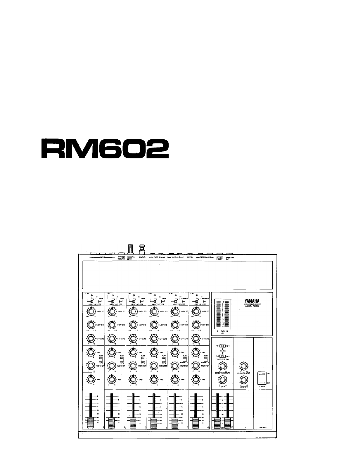
Thank you for choosing the Yamaha RM602 Recording Mixer. The RM602 is a
compact 6-in/2-out mixing console offering top-quality sound and a comprehensive
range of control features. The RM602 has been specifically designed to provide op
timum performance in a small sound recording system. To, take full advantage of
the outstanding performance and flexibility provided by this mixer, we urge you
to read this operation manual thoroughly.
I
Explanation of Graphical Symbols
CAUTION
RISK OF ELECTRIC SHOCK
DO NOT OPEN
CAUTION: TO REDUCE THE RISK OF
ELECTRIC SHOCK. DO NOT REMOVE
COVER (OR BACK). NO USER-SERVICEABLE
PARTS INSIDE. REFER SERVICING TO
QUALIFIED SERVICE PERSONNEL.
CAUTION (PREPARED IN ACCORDANCE WITH UL STANDARD 1270)
1. Read Instructions —All the safety and operating instructions should
be read before the appliance is operated.
2. Retain Instructions —The safety and operating instructions should
be retained for future reference.
3. Heed Warnings—All warnings on the appliance and in the operating
instructions should be adhered to.
4. Follow Instructions —All operating and use instructions should be
followed.
Water and Moisture —The appliance should not be used near water
—for example, near a bathtub, washbowl, kitchen sink, laundry
tub, in a wet basement, or near a swimming pool, etc.
6. Carts and Stands—The appliance should be used only with a cart
or stand that is recommended by the manufacturer.
7. Wall or Ceiling Mounting—The appliance should be mounted to
a wall or ceilling only as recommended by the manufacturer.
8. Ventilation—The appliance should be situated so that its location
or position does not interfere with its proper ventilation. For
example, the appliance should not be situated on a bed, sofa,
rug, or similar surface that may block the ventilation openings; or,
placed in a built-in installation, such as a bookcase or cabinet that
may impede the flow of air through the ventilation openings.
9. Heat—The appliance should be situated away from heat sources
such as radiators, heat registers, stoves, or other appliances
(including amplifiers) that produce heat.
The lightning flash with arrowhead
symbol, within an equilateral triangle,
Is Intended to alert you to the presence
of uninsulated "dangerous voltage"
within the product's enclosure that
may be of sufficient magnitude to
constitute a risk of electric shock to
persons.
The exclamation point within an
equilateral triangle is intended to alert
you to the presence of important
operating and maintenance (servicing)
instructions in the literature accom
panying the appliance.
10. Power Sources —The appliance should be connected to a power
supply only of the type described in the operating instructions or
as marked on the appliance.
11. Power-Cord Protection —Power-supply cords should be routed so
that they are not likely to be walked on or pinched by items
placed upon or against them, paying particular attention to cords
at plugs, convenience receptacles, and the point where they exit
from the appliance.
12. Cleaning—The appliance should be cleaned only as recommended
by the manufacturer.
13. Nonuse Periods—The power cord of the appliance should be
unplugged from the outlet when left unused for a long period
of time.
14. Object and Liquid Entry —Care should be taken so that objects
do not fall into and liquids are 'not spilled into the inside of the
appliance.
15. Damage Requiring Service —The appliance should be serviced by
qualified service personnel when:
A. The power-supply cord or the plug has been damaged; or
B. Objects have fallen, or liquid has been spilled into the
appliance; or
C. The appliance has been exposed to rain; or
D. The appliance does not appear to operate normally or exhibits
a marked change in performance; or
E. The appliance has been dropped, or the enclosure damaged.
16.
Servicing—The user should not attempt to service the appliance
beyond that described in the operating instructions. All other
servicing should be referred to qualified service personnel.
Page 4
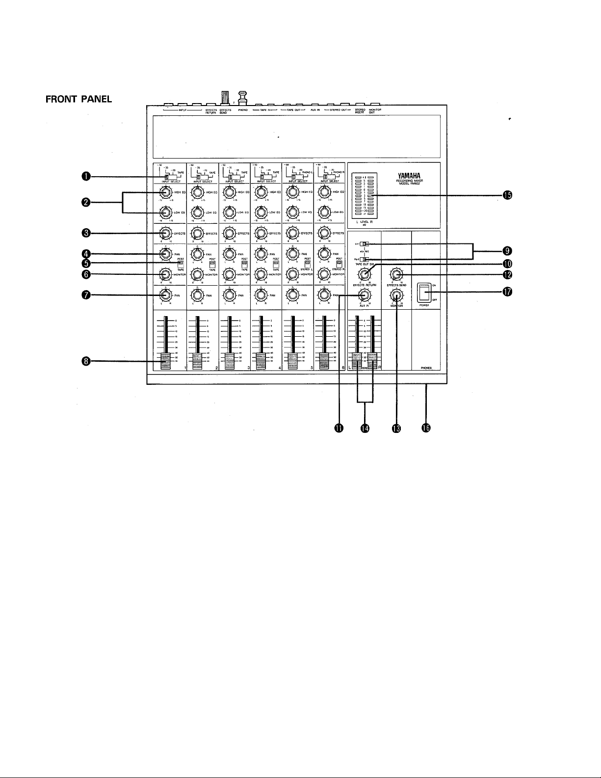
THE CONTROLS AND THEIR FUNCTIONS
INPUT SECTION
1. INPUT SELECTOR
This four-position input selector sets the input sensitivity
of the six channel inputs to -50, -35 or -20 dB. Note
also that the fourth position on channels 1 —4 is labelled
"TAPE", while the same position on channels 5 and 6
are labelled "PHONO L" and "PHONO R". When the
TAPE position on inputs 1—4 is selected, the corre
sponding TAPE IN input (see rear panel) is selected as
input rather than the channel INPUT. When the PHONO
position on inputs 5 and/or 6 is selected, the correspon
Be sure to turn down all faders when making input/
output connections.
Do not expose the RM602 to direct sunlight or other
sources of heat such as radiators, etc.
Irreparable damage may result from opening the
RM602 cabinet or attempting to alter the internal
circuitry.
ding phono input channel (PHONO L or PHONO R) is
selected.
The -50/-35/-20 dB sensitivity positions on the input
selector allow you to match the input sensitivity of each
input channel to match the source —e.g. microphone,
electronic music instruments or line level sources. This
allows you to use just about any source on any input
channel without overloading the mixer's electronics. Most
microphones —especially dynamic types —will work best
with the -50 dB input setting. Some high-output con
denser and electret mics may require the -35 dB setting.
PRECAUTIONS
Avoid dropping your RM602 or subjecting it to any
type of shock, as impaired performance may result.
Do not attempt to clean the RM602 with benzine or
other solvents, as these may cause discoloration or
deformation of the cabinet. Clean the unit with a soft,
dry cloth.
Page 5
I
The -35 dB setting is most ideal for direct input from
electric guitars and basses. The -20 dB setting is the
"line level" setting, accepting output from most line-level
sources: some synthesizers and electronic keyboards, and
most standard audio sources (tape players, etc.).
The TAPE position on the first four input channels lets
you switch from the INPUT sources to the outputs from
a 4-channel multitrack recorder without having to repatch
cables. This is particularly handy when you want to
remix the recorded material on 4-track tape down to
standard stereo format.
The PHONO L and PHONO R positions on the channel
5 and 6 selectors direct the output from the RM602's
built-in phono equalizer amplifier (see rear panel) to
channels 5 and 6, subject to all the controls available
on those channels.
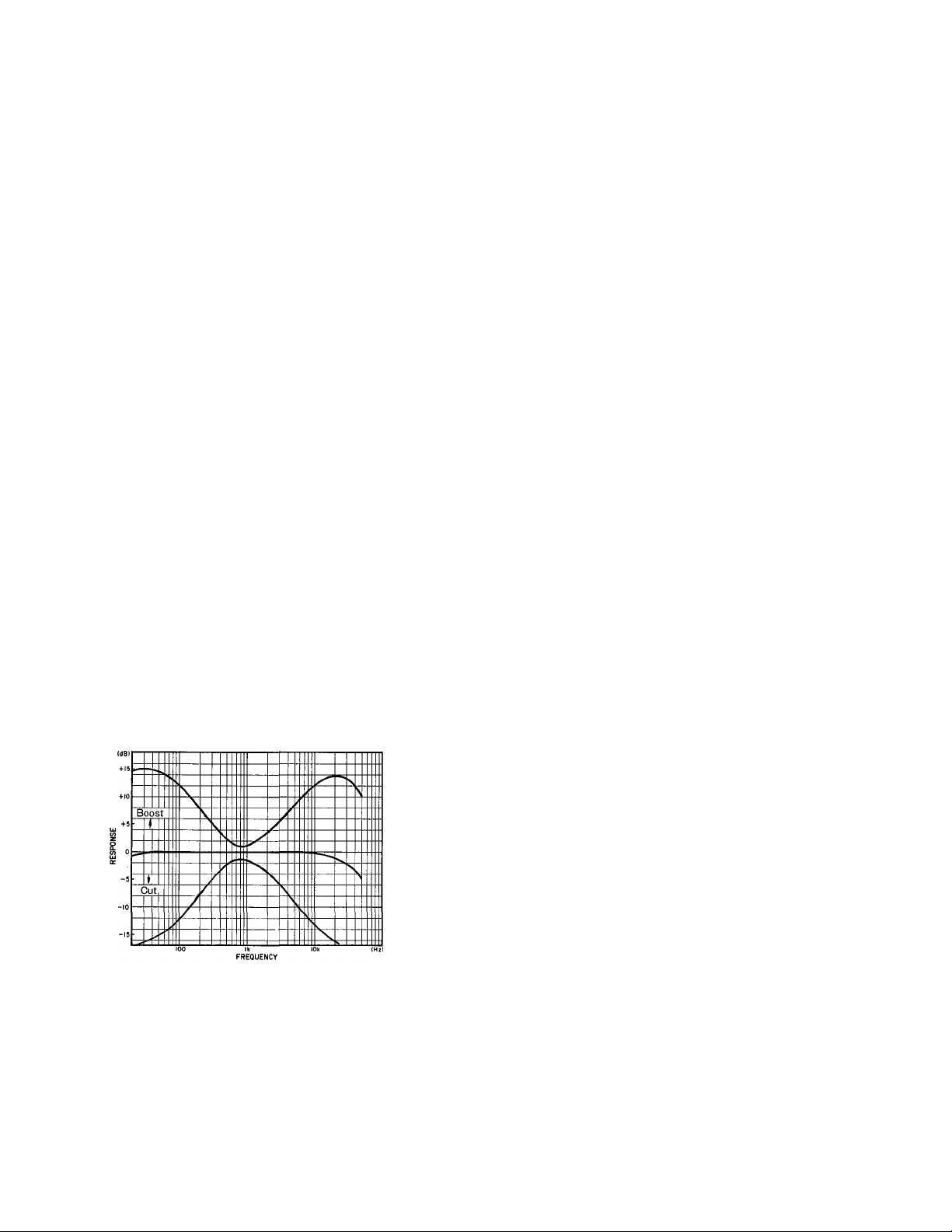
2. HIGH AND LOW EQ
The HIGH EQ and LOW EQ controls provide some tonal
control over the sound of each input channel. The HIGH
control provides plus or minus 15 dB of boost or cut in
the frequency range above 10 kHz ("shelving" EQ), while
the LOW control permits boosting or cutting frequencies
below 100 Hz by the same amount.
HIGH EQ is valuable for emphasising the high frequen
cies of certain instruments—cymbals, for example —and
for reducing hiss and noise on channels in which the
source has no essential frequencies in the range above
10 kHz.
LOW EQ can be boosted to make a bass sound bassier,
or cut to minimize rumble or microphone proximity
effects.
The signal sent to the effects buss is "post EQ/fader",
meaning that it is taken from a point after the equalizer
and channel fader circuitry.
4. MONITOR PAN CONTROL
One of the more attractive features of the RM602 is
its independent stereo monitor buss which makes it
possible to monitor a completely indepedent stereo mix
of the input channel or tape signals. The monitor PAN
control determines the placement of that channel's sig
nal in the stereo monitor sound field. Turning the pan
control fully to the left sends the signal only to the left
monitor buss—meaning that you hear the signal ony
from the left monitor speaker. Conversely, turning the
control all the way to the right sends the signal to the
right monitor buss only. Pan control positions in be
tween extreme left and right send a corresponding
amount of the signal to both busses, causing the
signal to appear in the corresponding position in the
stereo sound field.
MONITOR POST/TAPE SELECTOR
(CHANNELS 1-4)
MONITOR POST/STEREO L OR STEREO R
SELECTOR (CHANNELS 5 & 6)
On channels 1 through 4 this selector determines
whether the channel input source (POST) or the cor
responding tape input signal is sent to the monitor buss.
On channels 5 and 6 the choice is between the channel
input source or the left (CH 5) or right (CH 6) stereo
mixing buss signals. The fact that the channel signal
position is marked "POST" indicates that the channel
signal is derived from a point after the equalization and
fader stages.
3. EFFECTS SEND LEVEL
This control determines the amount of that channel's
signal which is sent to the internal effects mixing buss.
This effects buss feeds the rear-panel EFFECTS SEND
jack—via the master effects send level control (see
MASTER SECTION)—which normally feeds an external
echo or reverberation device. Having independent effects
send controls on each input channel means that the
amount of effect applied to the signal from each,
channel can be set independently.
6. MONITOR LEVEL
This control determines the amount of that channel's
signal (or the selected tape or stereo buss signal) which
is fed to the stereo monitor mixing buss via the monitor
PAN control discussed above. Independent monitor level
controls on each channels permit a monitor mix to be
set up independently from the input channel faders.
Page 6
7. PAN
This control has the same effect as the monitor PAN
control, discussed above, except that the channel signal
is panned across the main program buss which feeds
the mixer's main stereo outputs.
Panning is one of the mor^ "conventional" functions
that a stereo mixer performs, permitting acoustic place
ment of each instrument or group of instruments at any
desired location in the stereo sound field. I.e., the sound
of a particular instrument can appear to come from the
left speaker, right speaker, or anywhere in between. This
positioning of the signal from each input channel is per
formed using "pan pots". The position of the pan pots
relates directly to the acoustic position of the respective
channel's signal; pan pot fully clockwise means that the
sound comes from the right channel speaker, fully coun
terclockwise means that the sound comes from the left
channel speaker, and at intermediate pan pot settings
the sound appears to be located at the appropriate point
between the left and right speakers.
The pan pots can also be used to create the effect of
"floating" an instrument from one side of the stereo
sound stage to the other.
Generally, you'll use the pan pots to create the desired
acoustic image.
8. INPUT FADER
The input faders are what provide the actual "mixing"
function in a mixer. They permit individual adjustment of
the levels of the six input sources so you can achieve
just the right overall balance between instruments,
vocals, or whatever you are mixing.
These are the controls that you'll be using the most, and
how they are used can make the difference between
excellent and mediocre sound. Maximum signal-to-noise
ratio and minumum distortion, and therefore the best
sound, is generally obtained with fader settings between
about 1/3 and 3/4 of the fader scale. Fader settings that
are too high or too low should be avoided by increasing
or decreasing the level of the source whenever possible.
Most electronic keyboards and electric guitars have an
output level control, and microphone output level can be
adjusted by changing the distance of the microphone
from the sound source.
MASTER SECTION
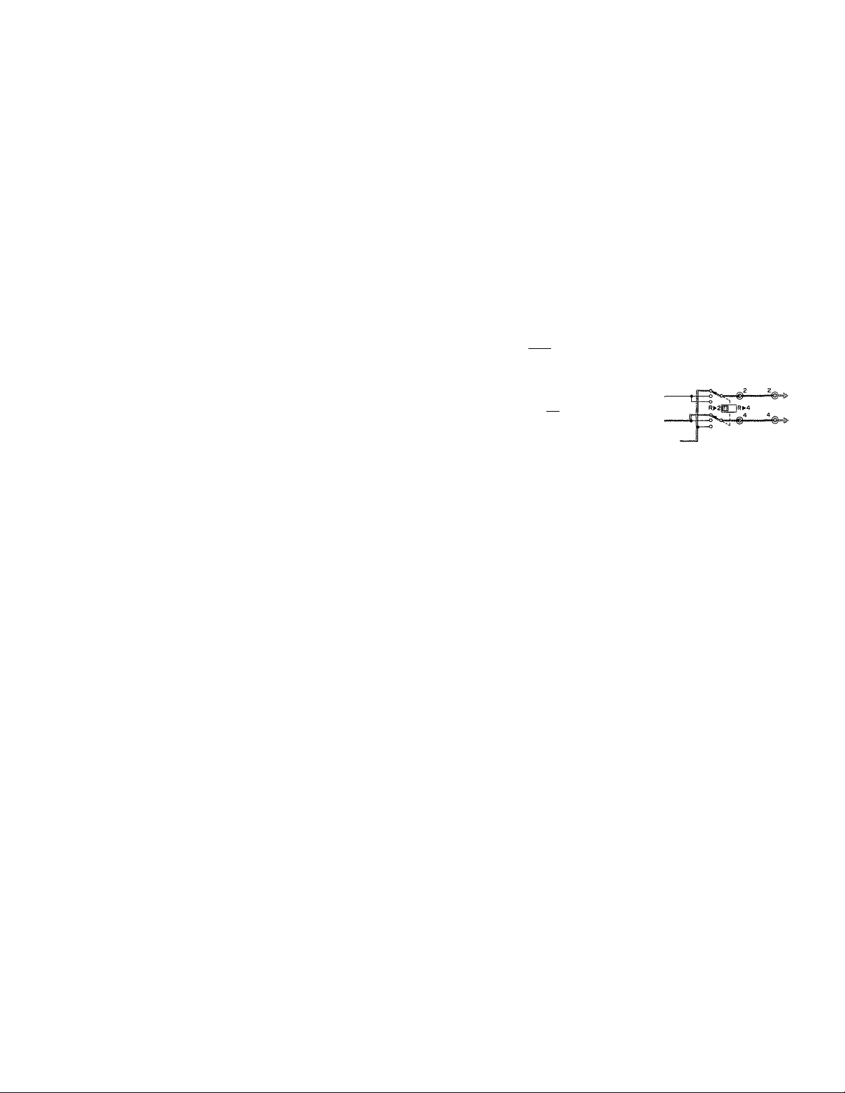
9. TAPE OUT SWITCHES
Rather than always having input channels 1 through 4
feed the corresponding TAPE OUT jacks, these switches
make it possible to send the left stereo buss signal to
either the TAPE OUT 1 or 3 jacks, and the right stereo
buss signal to either the TAPE OUT 2 or 4 jacks. This
makes it possible to reconfigure the system to mix the
input channels down to stereo on the recorder con
nected to the TAPE OUT jacks.
STEREO L Signal-
CH1 Signal-«“^
L»irÉ~li-»3
R»2l ED lR>-4
STEREO R Signal-
STEREO L Signal-
CHI Signal———
CH2 Signal'
CH4 Signal'
STEREO R Signal'
TAPE OUT LINE IN
-_@L_
10. EFFECTS RETURN
The output from the effects device you use (normally
echo or reverberation, fed by the EFFECTS SEND jack)
is returned to the EFFECTS RETURN jack and fed to
the stereo mixing buss via the EFFECTS RETURN con
trol. In other words, this control determines how much
of the externally processed signal is mixed back into the
main stereo program.
11. AUX IN
The RM602 has a pair of AUX IN terminals that make it
possible to mix an extra stereo signal in with the sources
present at the six input channels. The AUX IN control
adjusts the level of the AUX IN signal in relation to the
rest of the program. What you connect to the AUX IN
terminals depends entirely on your specific application,
but here are just a few examples:
1. You could connect the outputs from a stereo cassette
deck to the AUX IN terminals and play back a tape
of your favorite band. Then you can mix in your own
instrument and play along —a great way to practice.
2. With the same setup as in number 1, above, the
cassette tape can be supplying background music
while you mix in a narration and/or sound effects
for your audio/visual show and record the mixed
program on a second tape recorder.
3. Another possible use for this feature is as extra inputs
if the six main input channels are all in use. An elec
tronic keyboard or other line-level source could be
connected to the AUX IN terminals with a phone-to-
RCA pin plug adaptor and mixed in with the, rest of
the program using the AUX control. Of course you
don't get any tone control or panning capability, but
if you need the extra inputs, they're available.
Page 7

12. EFFECTS SEND MASTER LEVEL
This controls sets the overall level of the effects mix—
set up by the EFFECTS control on each input channel —
fed to the EFFECTS SEND jack. Normally, this control .
will be set to provide the optimum input level for the
effects device you are using. .
13. MONITOR MASTER LEVEL
This control determines the overall level of the monitor
mix —set up by the MONITOR level and PAN controls
on each input channel—fed to the stereo MONITOR
OUT jacks and the PHONES jack. Use the master
MONITOR control to set a comfortable headphone
listening level.
14. MASTER RADERS
These controls independently set the overall output level
from the left and right stereo busses. These signals ap
pear at the STEREO L OUT and STEREO R OUT jacks.
15. STEREO PEAK LEVEL METER
In the input fader section we discussed the importance
of proper fader setting in order to achieve the best pos
sible sound quality. The RM602's LED peak meters are
a tremendous aid in setting optimum fader levels.
Two meters are provided - one each for the left and
right stereo output channels. Each meter consists of 13
LED segments that light in sequence to show the peak
signal level for the respective channel. Meter display
range is from -20 dB to -t-8 dB. Levels below 0 dB
are displayed in green, 0, -t-1 and -1-3 dB levels are
displayed in orange, while -t-5 and -1-8 dB levels are
displayed in red. Watching the meters you can easily see
when signal levels are high enough to present a danger
of overload distortion — signals that light the red LEDs
are likely to cause distortion. On the other hand, if the
meters almost never reach the 0 dB level, then the over
all program level is too low. Once the optimum program
level has been set, peaks in the program will cause the
orange LEDs to flicker occasionally, and most of the
green LEDs will stay lit most of the time. This applies
mainly to the average music program. Some types of
program will have a completely different effect on the
meters, requiring appropriate level adjustment. In general,
though, it is a good idea to avoid a lot of peaks in the
red region. Also remember that when only one instru
ment is playing the level might look quite low on the
meters, but when instruments connected to all six
inputs start to play their individual levels can add up
to overload distortion. So check the meters when the
entire program is playing.
16. HEADPHONE JACK
This is a convenient feature in that it lets you directly
plug in any standard pair of stereo headphones'for
monitoring without the need for an external amplifier.
17. POWER SWITCH
This is the power switch. When the power is turned
ON, the lowest position on the level meter ("oo") will
light up.
Page 8
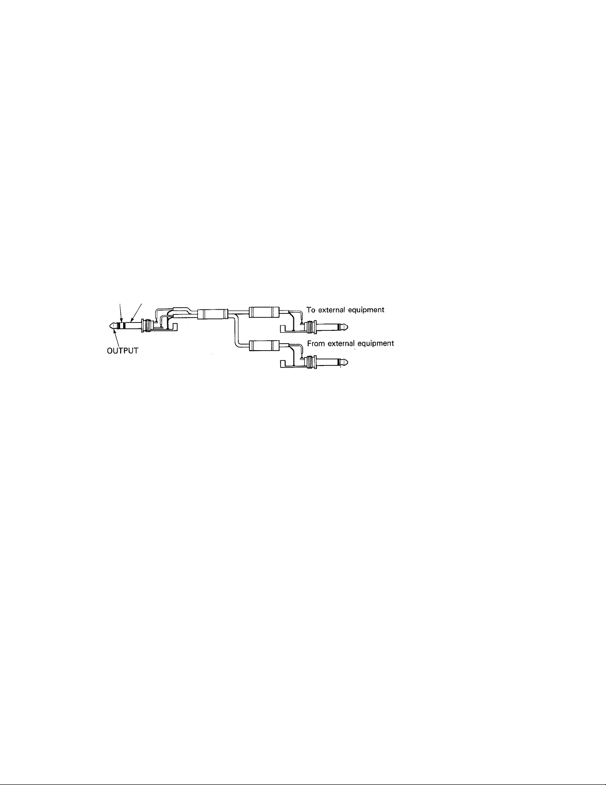
REAR-PANEL CONNECTIONS
REAR PANEL
1. CHANNEL INPUTS
These jacks are the main inputs to the RM602's six input
channels. They accept both line-level and microphone
input depending on the setting of the respective input
selector switch. Standard 1/4" phone jacks insure com
patibility with just about any electronic instrument or
microphone.
2. EFFECTS SEND AND RETURN
The output from the EFFECTS SEND jack is fed to
the input of an external signal processing device such
as delay or reverb (The Yamaha 015СЮ is a superb
digital delay unit, while the R1000 offers high-quality
reverb effects).
The output from the external signal processing device
is then fed back to the EFFECTS RETURN jack from
which it is mixed with the main stereo program via the
EFFECTS RETURN level control. When the EFFECTS
RETURN signal is received in stereo, input to both the
EFFECTS RETURN L and R terminals; when received in
mono, input to the L terminal.
3. PHONE EQ AMP INPUTS AND GND TERMINAL
The RM602 has a built-in phono equalizer amplifier
which makes it possible to directly connect the stereo
outputs from a conventional turntable (record player) to
these inputs, permitting the phono signal to be used
alone or mixed with other inputs. The left and right
phono channels feed input channels 5 and 6 when the
channel 5 and 6 input selectors are set to PHONO L
and PHONO R, respectively.
Be sure to connect the ground wire from the phone
player to the GND terminal. When the turntable is not
connected, insert a short plug into the PHONO terminal.
4. TAPE INPUTS AND OUTPUTS
Four inputs and outputs are provided for direct connec
tion to a 4-channel multitrack tape deck —such as the
Yamaha MT44D or MT44. The outputs from the tape
deck connect to the RM602 TAPE IN jacks, and the
tape deck inputs connect to the RM602 TAPE OUT
jacks. The tape inputs are selected for mixdown or
monitoring by setting the appropriate channel input
selectors (channels 1—4) to TAPE. Input channels 1
through 4 feed the respective TAPE OUT jacks.
These specialized inputs and outputs mean that the tape
deck can stay connected all the time —unlike many more
expensive mixers with which you have to keep patching
and repatching cables whenever you need to change
from line to tape input.
5. AUXILIARY INPUTS
Any line-level stereo (or mono if necessary) signal can
be added to the main program by these terminals. This
is a great place to connect the outputs from a stereo
cassette deck, for example.
6. STEREO OUTPUTS
These are the main outputs from the RM602. They
carry the stereo program set up at the input channels
and AUX inputs. Both standard 1/4" phone jack and
RCA pin jack output terminals are provided.
Page 9
I
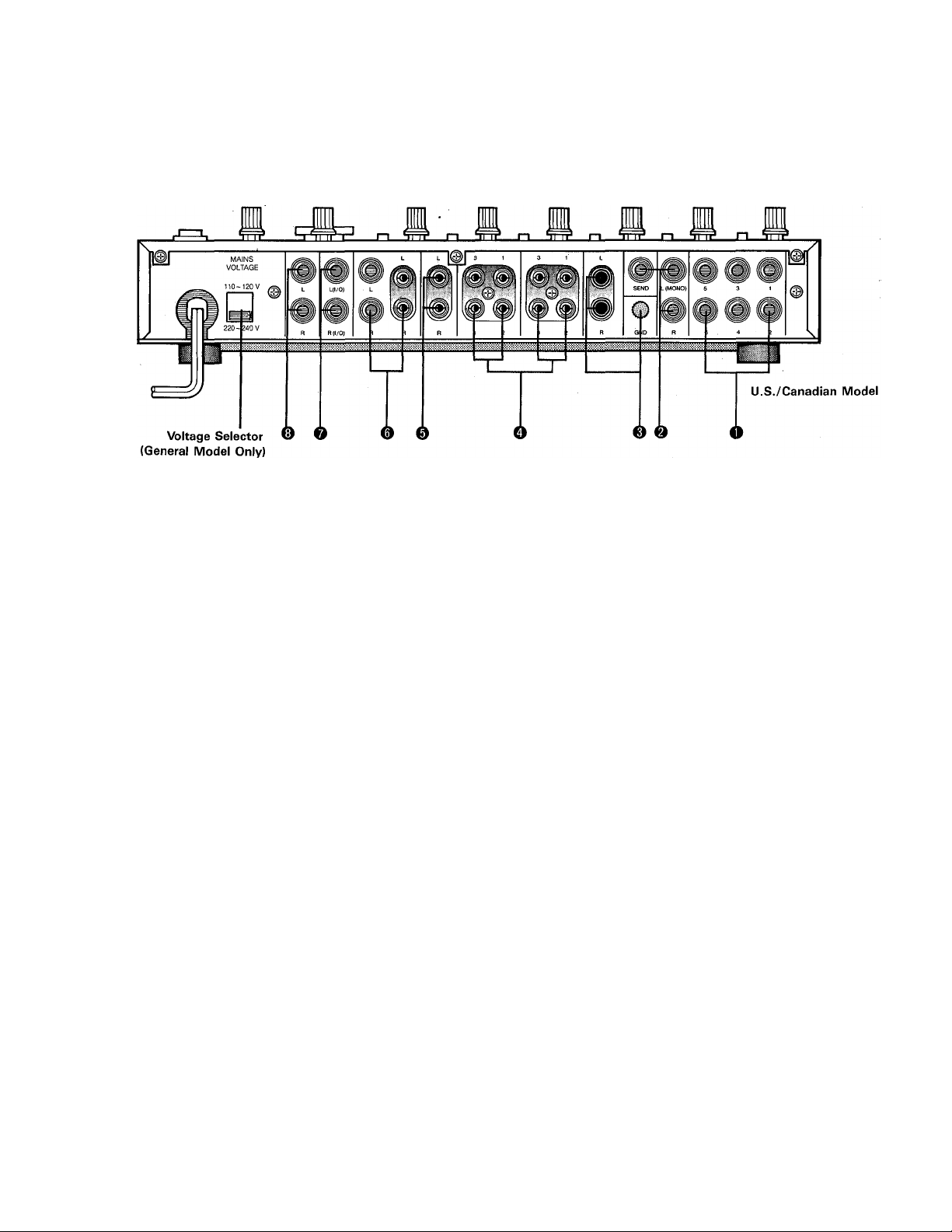
7. STEREO INSERT
This is a TRS (Tip Ring Sleeve) type phone jack, incor
porating both the insert send and receive lines. The
STEREO L and STEREO R INSERT points make it
possible to patch external signal processing equipment
independently into the left an^ right stereo busses,
preceding the master stereo faders. This is an ideal place
for insertion of graphic equalizers, Yamaha GQ1031 for
example, for precise response tailoring of the overall
stereo program. The TRS jacks are wired as shown in
the following diagram.
INPUT GND
8. MONITOR OUTPUTS
These are the line outputs from the stereo monitor buss.
They can be fed to a stereo power amplifier and monitor
speaker system, or directly to a pair of powered monitor
speakers such as the Yamaha MS10.
8
Page 10
APPLICATION EXAMPLES
1. Check out your original arrangements or make topquality demo tapes with an RM602 and a 4-channel
multitrack recorder (and you can play all the instru
ments youselfl).
. The ideal companion 4-track multitrack cassette
recorder for the RM602 is the Yamaha MT44D. Both
the RM602 and MT44D can be conveniently housed
in the RB35B rack, which also features a handly builtin patch bay.
2. The RM602 makes a great on-stage keyboard mixer.
You can control the balance and sound of your
keyboard setup before sending your signal to the
sound reinforcement mixer.
I
SYSTEM EXAMPLES: RECORDING SYSTEM
Performen's monitor
Compressor/limiter
3. The RM602 provides extensive mixing flexibility for
superb sound at band practice or mini-concerts.
4. If you're a "videophile," you need a good'multifunction mixing system for post-production work like
adding background music, narration or sound effects.
The RM602 is ideal.
Page 11

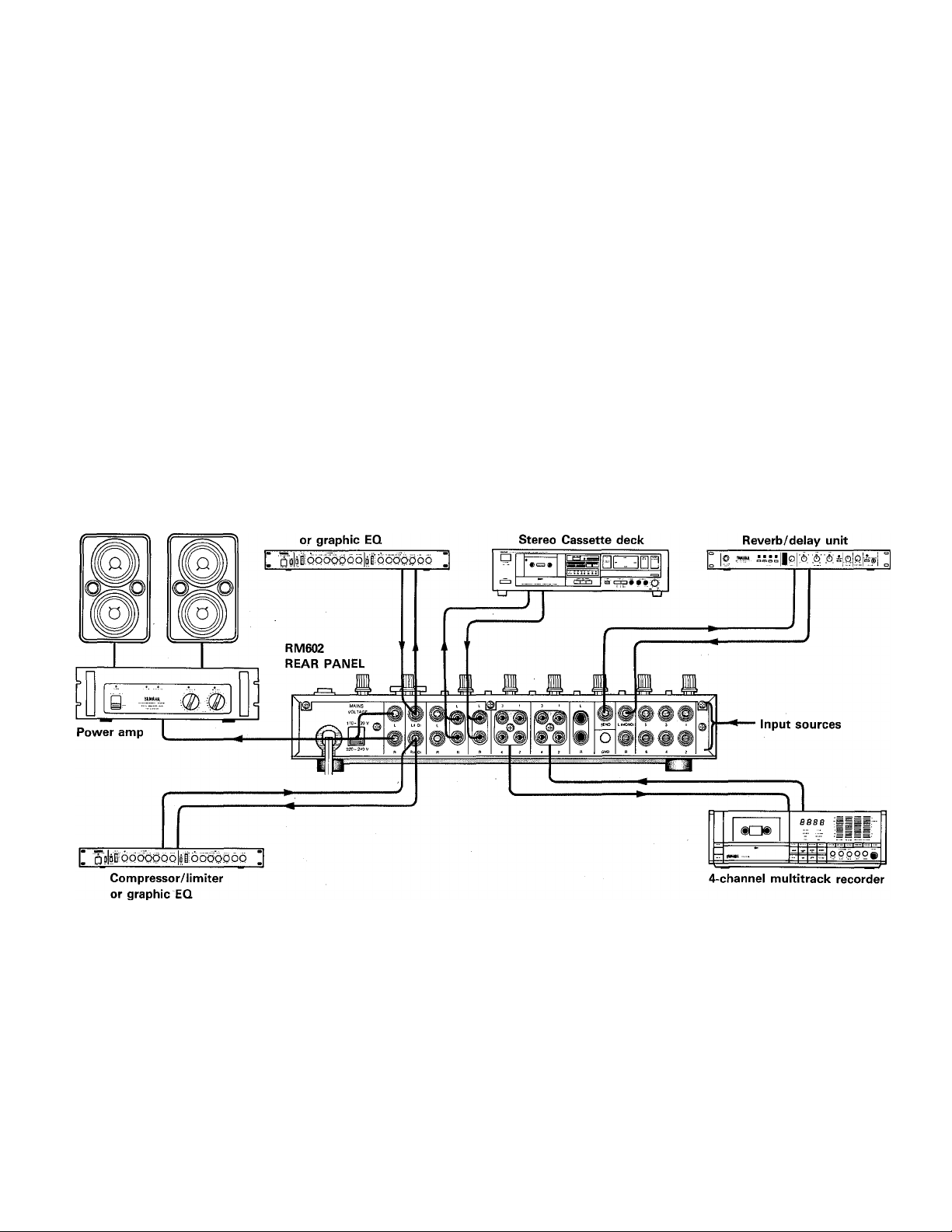
■ A MULTITRACK RECORDING SYSTEM
WHAT YOU NEED
Basically, all you need for a simple multitrack recording
setup are your instruments, a couple of good mics (if
you're going to be recording voice or acoustic in
struments), a 4-channel multitrack recorder such as the
Yamaha MT44D, an RM602 and a pair of headphones.
With this simple system you can create surprisingly com
plex recordings with your band, or by yourself. And
although the term "4-track recorder" seems to imply
that you can only record 4 individual parts, you can ac
tually record up to ten individual parts using a technique
known as "ping-ponging" (for details on this and many
other recording techniques, refer to the Yamaha Multi
track Guidebook). There's no better way to brush up
your compositions, arrangements and playing technique,
and then show it all off in the form of a high-quality
demo tape. To make a demo tape you'll need a regular
stereo cassette deck to "mix down" to from the original
4-track master tape.
MORE INSTRUMENTS FOR MORE CREATIVE
VERSATILITY
Once you get set up and rolling with your multitrack
system, you'll discover that the more instruments you
have available the better. This allows you to create more
diverse tonal textures and interesting combinations of
sounds (can you imagine 10 tracks of guitar? Interesting
at first but it would soon get pretty tiresome). One in
strument that is not so limited in terms of the sounds it
produces is the synthesizer. With carefully planned syn
thesizer "patches" that produce a diverse, but carefully
matched, range of voices, you could create a complete
composition that would not be in the least bit tiresome.
Yamaha offers an extensive line of synthesizers that are
ideal for the purpose —all the way from the tiny CS01-II
monophonic synthesizer right up to the professibnally
acclaimed DX-series Digital Programmable Algorithm
synthesizers.
Rhythm is another problem that most multitrack record
ists encounter sooner or later. Unless you're a drummer,
it's probably impractical to buy or borrow a complete
set of drums for your "studio." Once again, Yamaha
comes to the rescue with the exciting new RX-series
digital rhythm programmers. These are drum machines
that not only sound like the real thing (the drum sounds
are digitally recorded), but offer extensive programming
versatility as well as MIDI (Music Instrument Digital
Interface) compatibility.
EXTRA MONITORING CAPABILITY
With a little experience your recordings should start to
sound quite professional, and you'll probably find you
need a bit more monitoring versatility than a pair of
headphones provides. At this point you should check
out the Yamaha Producer Series MS10 Monitor Speaker.
This compact speaker features a high-quality built-in 20
watt power amplifier, and has volume, bass and treble
controls on the front panel.
Of course, if you want to go ail the way you can use a
high-quality stereo power amplifier and monitor speakers
— Yamaha offers an outstanding selection.
MORE TO COME
The Yamaha lineup of products specifically designed for
the small recording studio is expanding. More and more
products that will help you make professional-quality
recordings will become available in the near future.
10
Page 12

SPECIFICATIONS
Frequency Response
(@10 k-ohms. Rated Level)
Total Harmonic Distortion Less than 0.05%
(20 Hz ~ 10 kHz, 10 k-ohms, -MO dB)
Noise Level*
(20 Hz ~ 20 kHz, Input Shorted, INPUT SELECT
"-50”)
Equivalent Input Noise
Residual Noise (STEREO OUT EFFECTS SEND)
STEREO OUT - 89 dB
(MASTER Fader: nominal All CH Faders: minimum)
MONITOR OUT - 79 dB
(MONITOR Volume: nominal. All CH MONITOR
Volumes: minimum)
EFFECTS SEND
(EFFECTS SEND Volume: nominal. All CH
EFFECTS Volume: minimum)
Maximum Output Levei
(lOk-ohms, THD 0.2%, 20 Hz ~ 20 kHz)
Maximum Voitage Gain
CH INPUT to STEREO OUT
CH INPUT to MONITOR OUT
CH INPUT to EFFECTS SEND
CH INPUT to TAPE OUT
CH INPUT to ST INSERT OUT
TAPE IN to STEREO OUT
TAPE IN to MONITOR OUT
AUX IN to STEREO OUT
EFFECTS RETURN to STEREO OUT
ST INSERT IN to STEREO OUT
Crosstalk (1 kHz)
Input CH to Input CH
Input CH to Output CH
Equalizer Characteristics
HIGH-EO (10 kHz Shelving)
LOW-EQ (100 Hz Shelving)
Power Requirements
(UL, U.S.A.)
(General)
Power Consumpsion
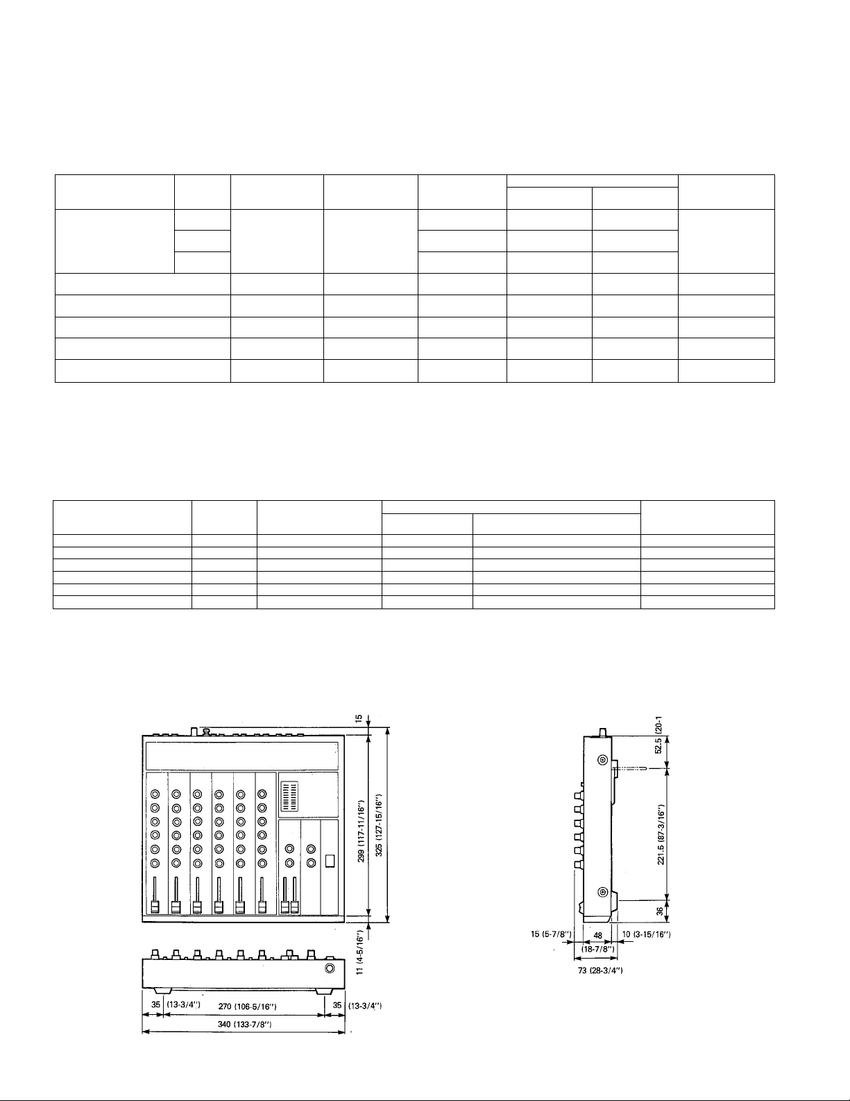
Dimensions (W X H x D)
Weight
Specifications subject to change without notice.
* Measured with a -6 dB/octave LPF 12.7 kHz.
20 Hz ~ 20 kHz
(-M, -2 dB)
•
-122 dB
-101 dB
- 89 dB
-M7.5 dB
52 dB
68 dB
58 dB
46 dB
46 dB
12 dB
22 dB
16 dB
16 dB
6 dB
- 60 dB
- 60 dB
± 15 dB
± 15 dB
AC120 V, 60 Hz
AC110, 120, 220, 240 V
50/60 Hz
15 W
340 X 73 X 325 mm
(13-3/8" X 2-7/8" X 12-3/4")
3.2 kg (7 lbs. 1 oz.)
OdB = 0.775 V r.m.s.
11
Page 13
INPUTS
INPUT
TERMINALS
CH INPUT
CH1-CH6
TAPE IN CH1~CH4
PHONO IN CHS, CH6
AUX IN (L, R)
EFFECTS RETURN (L, R)
ST INSERT IN (L, R)
OUTPUTS
OUTPUT TERMINALS
STEREO OUT (L, R)
MONITITOR OUT (L, R)
EFFECTS SEND
TAPE OUT (1-4)
ST INSERT OUT (L, R)
PHONES
INPUT
SELECT
-50 dB
-35 dB 20 k-ohms
-20 dB
OUTPUT
IMPEDANCE
330 ohms 10 k-ohms LINES
330 ohms
330 ohms 10 k-ohms LINES
330 ohms
330 ohms 10 k-ohms LINES
100 ohms
INPUT
IMPEDANCE
10 k-ohms TAPE DECK
47 k-ohms
10 k-ohms 600 ohms LINES
10 k-ohms 600 ohms LINES
10 k-ohms 600 ohms LINES
LOAD
IMPEDANCE
10 k-ohms LINES
10 k-ohms LINES
8 ohms PHONES
SOURCE
IMPEDANCE'
50-250 ohms
MIC or
600 ohms LINES
TURNTABLE
RATED LEVEL
SENSITIVITY*
(MAXIMUM GAIN)
-62 dB
(0.62 mV)
-47 dB
(3.5 mV)
-32 dB
(19.5 mV)
-22 dB
(61.5 mV)
-62 dB
(0.62 mV)
-26 dB
(38.8 mV)
-26 dB
(38.8 mV)
-16 dB
(123 mV)
-10 dB (245 mV) + 17.5 dB (5.81 V)
0 dB (775 mV) + 17.5 dB (5.81 V)
-10 dB (245 mV)
-10 dB (245 mV) + 17.5 dB (5.81 V)
-10 dB (245 mV) + 17.5 dB (5.81 V)
-22 dB (61.6 mV)
NOMINAL LEVEL
-50 dB
(2.5 mV)
-35 dB
(13.8 mV)
-20 dB
(77.5 mV)
-10 dB
(245 mV)
-50 dB
(2.5 mV)
-20 dB
(77.5 mV)
-20 dB
(77.5 mV)
-10 dB
(245 mV)
OUTPUT LEVEL
MAX. NON
CLIPPING LEVEL
+ 17.5 dB (5.81 V) PHONE JACK
- 4.5 dB (462 mV)
INPUT LEVEL
MAX. NON
CLIPPING LEVEL
-22.5 dB
(58.1 mV)
-7.5 dB
(327 mV)
-I-7.5 dB
(1.84 V)
■H7.5 dB
(5.81 V)
-22.5 dB
(58.1 mV)
+ 20.0 dB
(7.75 V)
•f20.0 dB
(7.75 V)
+ 20.0 dB
(7.75 V)
CONNECTOR
PHONE JACK & PIN JACK
PHONE JACK
PIN JACK
PHONE JACK (TRS)
STEREO PHONE JACK
CONNECTOR
PHONE JACK
PIN JACK
PIN JACK
PIN JACK
PHONE JACK
PHONE JACK
(TRS)
DIMENSIONS
* Sensitivity is the towest ievei that wiii produce an output of -10 dB.
Ail inputs and outputs are unbalanced.
Unit: mm (Inch)
0 dB = 0.775 Vr.m.s.
12
Page 14
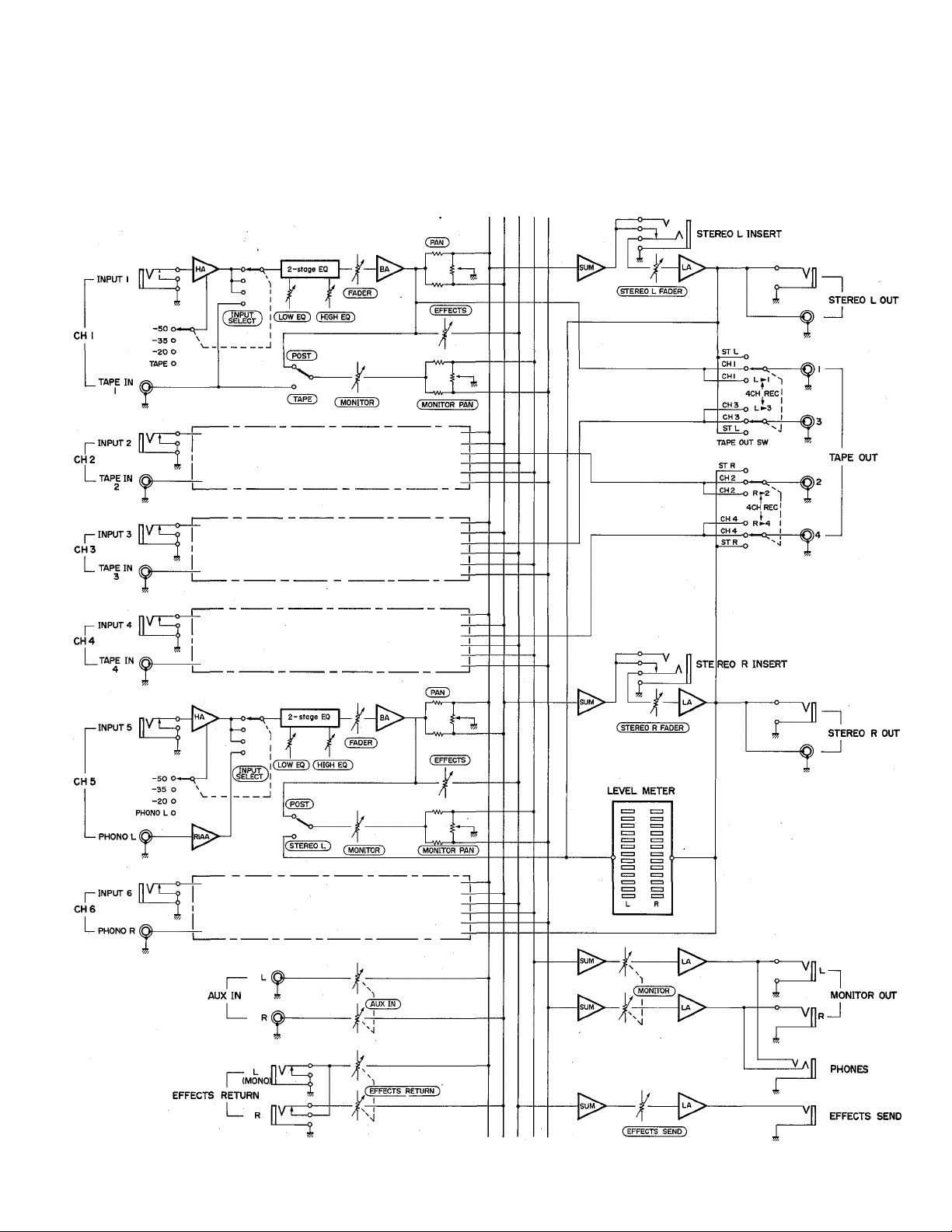
BLOCK DIAGRAM
|-MIX BUSSES-I
ID uj b p F
(T (t UJ P C
ID UJ U. Z z
Pf.li.0 0
b M ID s s
13
Page 15

LEVEL DIAGRAM
2-stage EQ
■INPUT
■V
FADER
ISUM'^
-------
o-
T~Va|| stereo
I
INSERT
CH K4
■TAPE IN(^
CH5,6
INPUT
PHONO @
-SOO"*—
-350 \
-200
TAPE O
V
-50 CM
-35 0
-20 0
PHONO O
------------
. j
INPUT
SELECT
INPUT
SELECT
AUX IN O-
EFFECTS RETURN
TAPE MONITOR
2-stoge^
POST
STEREO MONITOR
^ MONITOR PAN
MONITOR PAN
EFFECTS
RETURN
EFFECTS
-------------------
PAN
c:
EFFECTS
-
—
—
STEREO FADER
LEVEL METER
EFFECTS
SEND
-0—0
TAPE OUT SW
------------
ZI
STEREO OUT
O TAPE OUT
MONITOR OUT
zi
PHONES
vn effects
SEND
14
Page 16

15
Page 17

Nous vous remercions d’avoir choisi la table de mixage RM602 YAMAHA.
Le RM602 est une tablé de mixage compacte à 6 entrées/2 sorties offrant
un son de première qualité et une vaste gamme de commandes. Le
RM602 a été spécialement concu afin de fournir des performances
optimales dans un petit système d’enregistrement. Pour profiter au
maximum des performances exceptionnelles et de la souplesse
opérationelle de cette table de mixage nous vous demandons de lire
attentivement ce mode d’emploi.
PRECAUTIONS A PRENDRE
Assurez-vous de ramenez à zéro tous les
atténuateurs quand vous faites les connexions des
entrées et des sorties.
Assurez-vous que le RM602 est hors d’atteinte des
rayons directs du soleii ou à l’écart de sources de
chaleur (radiateurs, etc.).
Des dommages irréparables pourraient résulter de
l’ouverture du coffret ou d’une altération des circuits
internes.
Evitez de faire tomber ou de faire subir tout genre
de choc au RM602 car des performances altérées
pourraient en résulter.
N’utillsez pas de benzine ou autres diluants pour
nettoyer le RM602 car cela pourrait entraîner la
décoloration ou la déformation du coffret. Nettoyez
cet appareil avec un chiffon doux et sec.
16
Page 18

LES COMMANDES ET LEURS FONCTIONS
1. SELECTEUR D’ENTREE
Ce sélecteur d’entrée à quatre positions règle la
sensibilité d’entrée des six canaux d’entrée à -50, -35
ou - 20 dB. Notez aussi que la quatrième position des
canaux 1 - 4 est marquée “TAPE” (bande), alors que la
même position sur les canaux 5 à 6 est marquée
“PHONO L” (GAUCHE) et “PHONO R” (DROIT). Quand
la position TAPE des canaux 1-4 est sélectionnée,
l’entrée TAPE IN correspondante (voir panneau arrière)
est sélectionnée en tant qu’entrée plutôt que le canal
INPUT (entrée). Quand la position PHONO des entrées
5 et/ou 6 est sélectionnée, le canal d’entrée PHONO
correspondant (PHONO GAUCHE“L” ou PHONO DROIT
“R”) est sélectionné.
Les positions de sensibilité -50/-35/-20 dB sur le
sélecteur d’entrée vous permettent d’adapter la
sensibilité d’entrée des canaux à la source, comme par
exemple avec un microphone, avec des instruments de
musique électroniques ou avec des sources à niveau
ligne. Cela vous permet d’utiliser à peu près n’importe
quelle source avec n’importe quel canal d’entrée sans
surchager la table de mixage électronique. La plupart
des microphones, et spécialement ceux de type
électrodynamique, donnent de meilleures performances
quand le sélecteur d’entrée est réglé sur -50 dB.
Certains microphones à condensateur de niveau élevé
et certains microphones à electret peuvent demander
un réglage de -35 dB. Le réglage de -35 dB est idéal
pour des entrées directes de guitares électriques et de
basses. Le réglage -20 dB est le réglage de “niveau
ligne”, acceptant des sorties de la plupart des sources
de niveau lignes: certains synthétiseurs et claviers
électroniques, ainsi que la plupart des sources audio
normalisées (magnétophones, etc.).
La position TAPE des quatre premiers canaux d’entrée
vous permet de passer des sources d’entrée aux sorties
d’un enregistreur multipiste à 4canaux sans avoir à
reconnecter les câbles. Cela est particulièrement utile
quand vous désirez remixer l’enregistrement d’une bande
4 pistes sur une bande stéréo standard.
Les positions PHONO L et PHONO R des sélecteurs des
canaux 5 et 6 dirigent la sortie de l’amplificateur égaliseur
phono incorporé RM602 (voir panneau arrière) vers les
canaux 5 et 6; toutes les commandes de ces canaux
seront alors utilisables.
17
Page 19

2. EGALISEURS AIGU ET GRAVE (HIGH & LOW EQ)
Les commandes HIGH EQ et LOW EQ fournissent un
contrôle de tonalité sur chaque canal d’entrée. La
commande HIGH (AIGU) fournit une accentuation ou
une réduction de plus ou moins 15 dB dans la bande dé
fréquence au dessus de 10 kHz (en pente), tandis que la
commande LOW (GRAVE) permet une accentuation ou
une réduction de même amplitude des fréquences en
dessous de 100 kHz.
L’égaliseur aigu (HIGH EQ) est précieux lorsque vous
désirez accentuer les hautes fréquences de certains
instruments (comme par exemple des cymbales), ou
lorsque vous désirez réduire le souffle et le bruit de
canaux qui n’ont pas de fréquences essentielles dans la
bande au dessus de 10 kHz.
L’égalisation grave (LOW EQ) peut être accentuée pour
rendre les basses plus graves, ou réduite pour minimiser
les ronflement à basse fréquence ou les effets de
proximité d’un microphone.
indépendants. La commande panoramique de contrôle
détermine la position du signal de ce canal dans le
champ sonore du circuit de contrôle stéréo. Bn tournant
la commande panoramique complètement vers la
gauche, on envoie le signal seulement au circuit commun
de contrôle de gauche—cela signifie que vous entendrez
le signal provenant seulement du haut-parleur de
contrôle de gauche. Réciproquement, en tournant la
commande complètement vers la droite, on envoie le
signal au circuit commun de contrôle de droite
seulement. En positionnant cette commande entre
l’extrême gauche et l’extrême droite, on envoie une
quantité de signal correspondante à chacun des circuits
communs, permettant ainsi au signal d’apparaître à
remplacement correspondant du champ sonore stéréo.
5. SELECTEUR DE CONTROLE POST/BANDE
(CANAUX 1—4)
SELECTEUR DE CONTRÔLE POST/STEREO
GAUCHE (L) OU STEREO DROITE (R) (CANAUX 5
&6)
Sur les canaux 1 à 4, ce sélecteur détermine si la source
d’entrée du canal (POST) ou si le signal d’entrée de
bande correspondant est envoyé au circuit commun de
contrôle.
Sur les canaux 5 et 6, le choix est entre la source d’entrée
du canal ou les signaux du circuit commun de mélange
stéréo gauche (canal 5) ou droit (canal 6). Le fait que la
position du signal du canal est identifiée par “POST”
signifie que le signal du canal est dérivé à partir d’un
point qui se situe après les étages de l’égaliseur et de
l’atténuateur.
3. NIVEAU DE DEPART D’EFFETS (EFFECTS SEND
LEVEL)
Cette commande détermine la quantité de signal de ce
canal envoyée au circuit commun interne d’effets de
mixage. Ce circuit commun d’effets alimente le jack de
départ d’effets (EFFECTS SEND)—par la commande
principale de départ d’effets (voir la section principale)—
qui alimente normalement un dispositif d’écho ou de
réverbération. Disposer de commandes de départ d’effets
indépendantes surchaque canal d’entrée signifie que le
niveau d’effets appliqué au signai de chaque canal peut
est réglable indépendamment.
Le signal envoyé au circuit commun d’effets est “après
egaliseur/atténuateur”, cela signifie que le signal est
pris à partir d’un point qui se situe après l’égaliseur et le
circuit de l’atténuateur.
4. COMMANDE PANORAMIQUE DE CONTRÔLE
(MONITOR PAN CONTROL)
Une des caractéristiques les plus intéressante du
RM602 est son circuit commun de contrôle stéréo
indépendant qui permet d’écouter un mélange stéréo
des signaux du canal d’entrée ou de bande complètement
6. NIVEAU DE CONTRÔLE
Cette commande détermine la quantité de signal de ce
canal (ou du signal de bande ou du circuit commun
stéréo sélectionné) qui alimente le circuit commun de
mélange de contrôle stéréo par la commande
panoramique de contrôle dont nous avons parlé plus
haut. Des commandes de niveau de contrôle
indépendantes sur chaque canal permettent au mélange
de contrôle d’être composé indépendamment des
atténuateurs de canal d’entrée.
18
Page 20

7. COMMANDE PANORAMIQUE (PAN)
Cette commande a le mêmë effet que la commande
panoramique de contrôle dont nous avons parlé plus
haut, sauf que le signal du canal est affecté au circuit
commun de programme principal qui aiimente ies sorties
principaies stéréo du méiangeur.
La fonction panoramique est une des fonctions ies plus
“banales” qu’une table de mixage stéréo peut exécuter,
permettant ia iocaiisation acoustique de chaque
instrument ou groupe d’instruments à n’importe quel
emplacement désiré dans le champ sonore stéréo. Le
son d’un instrument donné peut sembler provenir du
haut-parieur de gauche, du haut-parieur de droite ou de
n’importe quel endroit situé entre ces deux haut-parieurs.
Ce régiage du signai de chaque canai d’entrée s’effectue
en utilisant des “potentiomètres panoramiques”. La
position de ces potentiomètres panoramiques se
rapporte directement à ia position accoustique du signai
du canai respectif: ie potentiomètrè panoramique tourné
compiètement dans ie sens des aiguilies d’une montre
produira un son provenant du haut-parleur du canal
droit, ie bouton tourné complètement dans le sens
contraire des aiguiiles d’une montre produira un son
provenant du haut-parieur du canai gauche, le bouton
réglé sur une position intermédiaire produira un son
iocaiisé en conséquence, c’est à dire en un point situé
entre les haut-parleurs de gauche et de droite.
Les potentiomètres panoramique peuvent aussi être
utilisés pour créer un effet de “giissement” d’un
instrument de musique d’un côté de ia “scène” sonore
stéréo à i’autre.
Généraiement, vous utiiiserez ies boutons panoramiques
pour créer i’image accoustique désirée.
8. ATTENUATEUR D’ENTREE (INPUT FADER)
Les atténuateurs d’entrée sont les éléments qui
fournissent ia fonction effective de mixage sur une tabie
de mixage, ils permettent des réglages individuels de
niveaux des six sources d’entrée afin de vous donner ia
possibiiité d’obtenir ie juste équilibre générai entre ies
instruments, ies voix ou tout autre source sonore que
vous mixez.
Ce sont ies commandes que vous utiiiserez ie plus, et la
façon dont vous les utiliserez pourra faire ia différence
entre un exceiient son et un son médiocre. Le meiiieur
rapport signai sur bruit, le minimum de distorsion et ia
meilleure qualité sonore sont généralement obtenus en
réglant approximativement ies atténuateurs entre 1/3
et 3/4 de l’écheiie d’atténuation. Les réglages
d’atténuation trop haut ou trop bas doivent être évités
en accroissant ou en réduisant le niveau de ia source à
chaque fois que ceia est possible.
La plupart des claviers éiectroniques et dés guitares
éiectriques ont une commande de niveau de sortie, et ie
niveau de sortie du microphone peut être régié en ,
jouant sur ia distance qui ie sépare de ia source sonore.
SECTION PRINCIPALE
9. COMMUTATEURS DE SORTIE DE BANDE (TAPE
OUT)
Plutôt que de toujours avoir ies canaux d’entrée 1 à 4
alimentant ies prises de sortie de bande (TAPE OUT),
ces commutateurs vous permettent d’envoyer ie signal
du circuit commun stéréo de gauche aux prises TAPE
OUT 1 ou 3, et le signal du circuit commun stéréo de
droite aux prises TAPE OUT 2 ou 4. Cela vous permet de
recomposer le système pour mixer les canaux d’entrée
en stéréo sur le magnétophone connecté aux prises
TAPE OUT.
STEREO L Signal
STEREO R Signal-
-------
TAPE OUT UNE IN
L»l|~niL»3
RP-21 Ò 1RK4
STEREO L Signal
CHI Signal
STEREO R Signal
TAPE OUT LINE IN
-------------
%>-
10. RETOUR D’EFFETS
La sortie du dispositif d’effets que vous utilisez
(normalement écho ou réverbération, alimenté par le
jack de départ d’effets (EFFECTS SEND)) est renvoyée
au jack de retour d’effets (EFFECTS RETURN) et
alimente le circuit commun de mixage stéréo par la
commande de retour d’effets. En d’autres mots, cette
commande détermine la quantité du signal traité
extérieurement qui est remixé dans le programme
stéréo principal.
11. ENTREE AUXILLIAIRE (AUX IN)
Le RM602 a une paire de bornes d’entrée auxiliaire
(AUX IN) qui permettent de mixer un signal stéréo
supplémentaire avec les sources présentes aux six
canaux d’entrée. La commande AUX IN règle le niveau
du signal AUX IN en relation avec le reste du programme.
Ce que vous connectez aux bornes AUX IN dépend
entièrement de votre utilisation spécifique, mais voici
tout de même quelques exemples;
1. Vous pourriez connecter les sorties d’un
magnétocassette aux bornes AUX IN et reproduire
une bande de votre groupe préféré. Ensuite vous
pouvez mixer votre propre instrument avec et jouez
en suivant la musique; c’est une manière formidable
de s’entraîner.
2. En utilisant la même connexion que dans l’exemple
ci-dessus, le magnétocassette peut fournir une
musique de fond pendant que vous mixez avec cette
musique de fond des commentaires et/ou des effets
spéciaux pour votre spectacle audio-visuel et
enregistrer le programme mixé sur un second
magnétophone.
19
Page 21

3. Une autre possibilité d’utilisation de ce dispositif est
de se servir de ces entrées auxiliares en tant
qu’entrées supplémentaires si les six canaux d’entrée
principaux sont utilisés. Un clavier électronique ou
une autre source de niveau ligne peuvent être
connectés aux bornes AUX IN avec un adaptateur
intermédiaire jack-broches RCA et mixés avec le
reste du programme en utilisant la commande AUX.
Vous n’avez, bien sûr, aucune commande de tonalité
ou de possibilité panoramique, mais si vous le désirez
les entrées supplémentaires sont disponibles.
12. NIVEAU PRINCIPAL DE DEPART D’EFFETS
(EFFECTS SEND MASTER LEVEL)
Ces commandes règlent le niveau général du mélange
d’effets—déterminé par la commande d’effets de chaque
canal d’entrée—alimentant le jack de départ d’effets.
Normalement, cette commande sera réglée de manière
à fournir le niveau optimum d’entrée au dispositif d’effets
que vous utilisez.
13. NIVEAU PRINCIPAL DE CONTRÔLE (MONITOR
MASTER LEVEL)
Cette commande détermine le niveau général du
mélange de contrôle—réglé par le niveau de contrôle et
par les commandes panoramique de chaque canal
d’entrée—alimentant les jacks de sortie de contrôle
(MONITOR OUT) et le jackcasque(PHONES). Utilisez la
commande de contrôle principale pour obtenir un niveau
d’écoute au casque agréable.
atteignant 0 dB, cela signifie que votre niveau de
programme général est trop bas. Une fois le niveau
optimal de programme réglé, les crêtes de ce programme
doivent faire clignoter occasionnellement des diodes
oranges, et maintenir la majorité des diodes vertes
allumés la plupart du temps. Cela s’applique surtout aux
programmes musicaux ordinaires.
Certains types de programmes auront un effet
complètement différent sur les indicateurs, nécessitant
des réglages appropriés. En général il est recommandé
d’éviter un nombre trop important de crêtes dans la
partie rouge de ces indicateurs. Rappelez-vous aussi
que quand il n’y a qu’un seul instrument qui joue le
niveau peut paraître bas sur les indicateurs, mais quand
les instruments connectés aux six entrées commencent
à jouer ensemble, les niveaux de chaque instrument
peuvent s’additioner et créer une distorsion. Il vous faut
donc vérifier les indicateurs quand l’ensemble du
programme est joué.
16. JACK CASQUE (HEADPHONE)
Ceci est un dispositif pratique qui vous permet de
connecter un casque stéréo normalisé pourcontrôler le
son sans avoir besoin d’un amplificateur externe.
17. COMMUTATEUR D’ALIMENTATION (POWER)
Ceci est le commutateur d’alimentation. Quand
l’alimentation est en circuit (ON), la position la plus
basse de l’indicateur de niveau (“oo”) s’allumera.
14. ATTENUATEURS PRINCIPAUX (MASTER
FADE RS)
Ces commandes règlent indépendamment le niveau de
sortie général des circuits communs gauche et droit.
Ces signaux arrivent aux prises de sortie stéréo gauche
et droite (STEREO L OUT et STEREO R OUT).
15. INDICATEURS DE NIVEAU DE CRETE STEREO
(STEREO PEAK LEVEL METER)
Dans la partie atténuateur d’entrée de ce manuel, nous
avons parlé de l’Importance d’un réglage correct des
atténuateurs en vue d’obtenir la meilleure qualité sonore
possible. Les indicateurs de niveau de crêtes à diodes
du RM602 sont d’une aide très précieuse pour un
réglage optimum des niveaux des atténuateurs.
Deux indicateurs sont fournis—un pour le canal de
sortie de gauche et un pour le canal de sortie de droite.
Chaque indicateur est constitué de 13 segments qui
s’allument en séquence pourdonner le niveau du signal
de crête du canal correspondant. La plage d’affichage
des indicateurs est de -20 dB à -1-8 dB. Les niveaux
inférieurs 0 dB sont affichés en vert, les niveaux 0, -M et
-1-3 dB en orange, et les niveaux -t-5 et -1-8 dB en rouge.
En regardant ces indicateurs vous pouvez facilement,
vous rendre compte quand les niveaux du signal sont
trop élevés pour présenter un danger de distorsion—les
signaux qui allument les diodes rouges ont beaucoup
de chance de créer une distorsion. D’un autre côté, si les
indicateurs n’indiquent presque jamais un niveau
20
Page 22

CONNEXIONS DU PANNEAU ARRIERE
PANNEAU ARRIERE
Sélecteur de tension O O
(modèle général seulement)
Modèle U.S.A/Canada
1. ENTREES DE CANAUX
Ces jacks sont les entrées principales des six canaux
d’entrée du RM602. Ils acceptent à la fois les entrées à
niveau ligne et les entrées microphone, selon le réglage
du commutateur d’entrée respectif. Les jacks
téléphoniques 1/4 pouce normalisés assurent une
compatibilité avec pratiquement tous les genres
d’instruments électroniques et de microphones.
2. DEPART ET RETOUR D’EFFETS (EFFECTS SEND
AND RETURN)
La sortie du jack de départ d’effets (EFFECTS SEND) est
connectée à l’entrée d’un dispositif de traitement du
signal extérieur comme par exemple une unité de retard
ou de réverbération (Le DI 500 Yamaha est une splendide
unité de retard numérique, tandis que le RI 000 offre des
effets de réverbération de haute qualité).
La sortie du dispositif de traitement du signal extérieur
est alors renvoyée au jack de retour d’effets (EFFECTS
RETURN) à partir duquel le mélange se fait avec le
programme stéréo principal par la corn mande de niveau
de retour d’effets (EFFECTS RETURN). Quand le signal
de retour d’effets (EFFECTS RETURN) est reçu en
stéréo, il est reçu par les bornes d’entrée gauche (L) et
droite (R) du retour d’effets (EFFECTS RETURN); quand
le signal est reçu en mono, il est reçu par la borne
d’entrée L (gauche).
3. ENTREES DE L’AMPLIFICATEUR EGALISEUR
PHONO ET BORNE DE PRISE DETERRE (PHONO
EQ AMP INPUTS AND GND TERMINAL)
Le RM602 comporte un amplificateur égaliseur phono
incorporé qui donne la possibilité de connecter
directement les sorties stéréo d’une table de lecture
conventionelle à ces entrées; cela permet d’utiliser le
signal de la table de lecture tout seul ou mixé avec les
autres entrées. Les canaux gauche et droit de la table
de lecture sont connectés aux canaux d’entrée 5 et 6
quand les sélecteurs d’entrée des canaux 5 et 6 sont
réglés respectivement sur PHONO L (GAUCHE) et
PHONO R (DROIT).
Assurez-vous de connecter le câble de prise de terre de
la table de lecture à la borne de prise de terre. Quand la
table de lecture n’est pas connectée à la borne de prise
de terre, insérez une prise de court-circuit dans la borne
PHONO.
4. ENTREES ET SORTIES BANDE (TAPE INPUTS
AND OUTPUTS)
Quatre entrées et sorties sont prévues pour une
connexion directe avec un magnétophone multipiste à
4 canaux—comme par exemple le MT44D ou MT44
Yamaha. Connectez les sorties du magnétophone aux
prises TAPE IN du RM602 et les entrées du
magnétophone aux prises TAPE OUT du RM602. Les
entrées du magnétophone sont sélectionnées en vue
du mixage ou du contrôle en réglant les sélecteurs
d’entrée des canaux correspondants (canaux 1 —4) sur
TAPE. Les canaux d’entrée de 1 à 4 alimentent les
prises TAPE OUT respectives.
Ces entrées et sorties spécifiques permettent au
magnétophone de rester branché en permanence—à la
différence de beaucoup d’autres tables de mixage
coûteuses avec lesquelles vous avez besoin de
connecter et reconnecter les câbles à chaque fois que
vous effectuez un changement d’une entrée ligne à une
magnétophone.
21
Page 23

5. ENTREES AUXILLIAIRES (AUX INPUTS)
N’importe quel signal de niveau lignestéréo(ou mono si
nécessaire) peut être ajouté au programme principal
grace à ces bornes. Ces bornes sont parfaites pour
connecter, par d’exemple, les sorties d’un magnétophone
stéréo.
6. SORTIES STEREO (STEREO OUTPUTS)
Ces sorties sont les sortiës principales du RM602. Elles
délivrent l’ensemble du programme stéréo déterminé
sur les canaux d’entrée et les entrées AUX. Les bornes
de sortie sont équipées de jacks téléphoniques 1/4
pouce normalisé et de prises à broche RCA.
I
7. INSERTION STEREO (STEREO INSERT)
Ceci est un jack téléphonique de type TRS, incorporant
les lignes de départ et de retour d’insertion. L'es points
d’insertion (INSERT) STEREO L (GAUCHE) et STEREO
R (DROIT) permettent d’insérer le signal externe d’un
équipement de traitement indépendamment dans les
circuits communs stéréo gauche et droit, avant les
atténuateurs stéréo principaux. C’est l’endroit idéal
pour insérer un égaliseur graphique, par exemple le
GQ1031 Yamaha, pour une réponse très précise de
l’ensemble du programme stéréo. Les jacks TRS sont
câblés comme indiqué ci-dessous.
8. SORTIES DE CONTRÔLE (MONITOR OUTPUTS)
Ce sont les sortie de lignes d’un circuit commun
moniteur stéréo. Ces sorties peuvent être connectées à
un amplificateur stéréo et à un système de hautparleurs de contrôle, ou directement à une paire de
haut-parleurs de contrôle, comme par exemple les
MS10 Yamaha.
Entrée Masse
22
Page 24

EXEMPLES D’UT!LISATION
1. Vérifiez un arrangement musicai originai ou faites
des bandes de démonstration de première quaiité
avec le RM602 et un enregistreur muitipiste à 4
canaux (et vous pouvez jouer tous ies instruments
vous-même).
Le magnétocassette muitipisteà4 pistes compagnon
idéal du RM602 est le MT44D Yamaha. Le RM602 et
le MT44D peuvent tout deux être avantageusement
placés dans le châssis RB35B, qui comporte une
baie de répartition incorporée.
2. Le RM602 constitue une tabie de mixage pour
ciaviers éiectroniques de première quaiité pour ies
concerts.
Vous pouvez contrôler l’équilibre et le son de votre
clavier avant d’envoyer ie signai au méiangeur de
sonorisation.
EXEMPLES: SYSTEME D’ENREGISTREMENT
Enceintes de contrôle
des interprètes Compresseur/limiteur
3. Le RM602 offre une grande flexibiiité de mixage pour
des répétitions ou de petits concerts.
4. Si vous êtes un “vidéophile” vous avez Besoin d’un
bon système de mixage à fonctions multiples pour le
travail de post-production, comme, par exempie,
l’addition d’un fond sonore, de commentaires ou
d’effets spéciaux.
Là encore, le RM602 est idéal.
23
Page 25

SYSTEME D’ENREGISTREMENT MULTIPISTE
DE QUOI AVEZ VOUS BESOIN?
A la base, tout ce dont vous avez besoin pour un
enregistrement multipistes se résume à: vos instruments'
de musique, une paire de bpns microphones (si vous
enregistrez des parties vocaies ou des instruments
acoustiques), un enregistreur muitipiste à 4 canaux
comme ie MT44D Yamaha, un RM602 et un casque.
Avec ce système très simpie vous pouvez créer des
enregistrements d’une compiexité surprenante avec votre
groupe ou tout seui. Le terme “magnétophone 4 pistes”
sembie impiiquer que vous ne pouvez enregistrer que 4
parties distinctes, aiors qu’en fait vous pouvez en
enregistrer jusqu’à 10 parties en vous servant de la
technique connue sous ie nom de “ping-ponging”
(enregistrement combiné en changeant de piste). (Pour
des détaiis à ce sujet et à propos d’autres techniques
d’enregistrement, référez vous au guide muitipiste
Yamaha). Il n’y a pas de meilleur moyen de “polir” vos
compositions, vos arrangements musicaux, votre
technique instrumentale, et d’obtenir des bandes de
démonstration de haute qualité. Pour faire des bandes
de démonstration vous aurez besoin d’une platine
magnétocassette stéréo normale pour “réduire” en stéréo
les 4 pistes de la bande “mère”.
PLUS D’INSTRUMENTS POUR UNE PLUS GRANDE
SOUPLESSE DE CREATION
Une fois que vous aurez pris l’habitude de votre système
multipistes, vous vous rendrez compte que plus vous
avez d’instruments disponibles, et plus vous aurez de
possibilités de création. Cela vous permet de créer plus
de diversité dans la texture musicale et aussi
d’intéressantes combinaisons sonore (pouvez-vous
imaginer 10 pistes de guitare? Intéressant en premier
lieu mais cela risquerait de devenir un peu fatiguant à la
longue). Un instrument sans limites dans ce sens est le
synthétiseur. Avec une partie musicale soigneusement
préparée, le synthétiseur pouvant produire des timbres
très variés et très riches, vous pourrez créer ainsi une
complète composition musicale qui sera loin d’être
ennuyeuse.
Yamaha offre une gamme très diversifiée de synthétiseurs
I
idéaux pour ce genre de besoin—cette gamme va du
petit synthétiseur monophonique CS01-II jusqu’au
synthétiseur professionnel numérique à programmation
algorithmique de la gamme DX.
La section rythmique est un autre problème que la
plupart des personnes enregistrant en multipistes
rencontrent tôt ou tard. A moins que vous ne soyez un
batteur, il est pratiquement impossible d’acheter ou
d’emprunter une batterie pour votre “studio
d’enregistrement”. Une fois de plus, Yamaha est là pour
vous offrir la solution: les programmeurs de rythme
numériques de la nouvelle gamme RX.
Ce sont des machines à rythmes qui ne se contentent
pas d’avoir la même sonorité que les vrais instruments (le
son est enregistré numériquement), mais offrent une
programmation très diversifiée ainsi que la compatibilité
MIDI (Music Instrument Digital Interface).
DES POSSIBILITES SUPPLEMENTAIRES DE
CONTROLE
Avec un peu d’expérience vos enregistrements
prendrons un aspect professionel, et vous vous rendrez
certainement compte que vous avez besoin d’autres
moyens de contrôle que le casque fourni. A ce moment-
là, vous devriez essayer les haut-parleurs de contrôle de
la gamme producteur Yamaha MSI 0 pour sentir la
différence. Ces haut-parleurs compacts ont pour
caractéristiques un amplificateur incorporé de 20 W et
des commandes pour le volume, grave et l’aigu en
façade.
Bien sûr, si vous voulez aller jusqu’au bout vous pouvez
utiliser un amplificateur stéréo de haute qualité et des
haut-parleurs de contrôle.
Yamaha vous offre un choix exceptionnel.
ENCORE PLUS A VENIR
La gamme des produits Yamaha spécialement conçue
pour les petits studios d’enregistrement est en pleine
expansion. De plus en plus de produits, qui vous aideront
à faire des enregistrements de qualité professionelle,
seront disponibles dans un futur proche.
24
Page 26

CARACTERISTIQUES
Réponse en fréquence
(a 10 k-ohms, niveau nominal)
Distortion harmonique totaie
(20 Hz—10 kHz, 10 k-ohms, -MO dB)
Niveau de bruit*
(20 Hz—20 kHz, entrée en court circuit, séiecteur
d’entrée (INPUT SELECT) “-50”).
Bruit d’entrée équivalent -122 dB
Bruit résiduel (départ d’effets spéciaux/sortie stéréo)
(STEREO OUT EFFECTS SEND)
Sortie stéréo (STEREO OUT)
(Atténuateur principal: nominal. Tous les
atténuateurs de canaux: minimum)
Sortie de contrôle (MONITOR OUT)
(Volume de contrôle: nominal. Volumes de tous
les contrôles de canaux: minimum)
Départ d’effets (EFFECTS SEND)
(Volume départ d’effets: nominal. Volume des
effets de tous les canaux: minimum)
Niveau de sortie maximum
(10 k-ohms, DHT 0,2%, 20 Hz-20 kHz)
Gain de tension maximum
Entrée canal à sortie stéréo 52 dB
Entrée canal à sortie de contrôle 68
Entrée canal à départ d’effets 58 dB
Entrée canal à sortie bande 46
Entrée canal à sortie insertion stéréo 46 dB
Entrée bande à sortie stéréo 12 dB
Entrée bande à sortie de contrôle 22
Entrée AUX à sortie stéréo 16
Retour d’effets à sortie stéréo 16 dB
Entrée insertion stéréo à sortie stéréo
Diaphonie (1 kHz)
Canal d’entrée à canal d’entrée
Canal d’entrée à canal de sortie
20 Hz—20 kHz
(-M, -2 dB)
moins de 0,05%
-F 17,,5 dB
-101
- 89
- 79
- 89
- 60
- 60
dB
dB
dB
dB
dB
dB
dB
dB
dB
6
dB
dB
Caractéristiques de l’égaliseur
Egaliseur aigu (10 kHz en pente)
Egaliseur grave (100 Hz en pente)
Alimentation
(UL, U.S.A)
(Général)
Consommation
Dimensions (L X H X P)
Poids
± 15 dB
± 15 dB
CA 120 V, 60 Hz
CA 110 V, 120, 220, 240 V
50/60 Hz
15 W
340 X 73 X 325 mm
3,2 kg
Caractéristiques modifiabies saris préavis.
*Mesuré avec un fiitre passe-bas - 6 dB/octave 12,7 kHz.
0 dB = 0,775 V efficace
25
Page 27

ENTREES
I
Prises
d’entrée
CH INPUT
CH1 -CH6
TAPE IN CH1 - CH4
PHONO IN CH5,CH6
AUX IN (L, R)
EFFECTS RETURN (L, R) 10 k-ohms Lignes 600 ohms
ST INSERT IN (L, R)
Sélecteur
d’entrée
- 50 dB
- 35 dB 20 k-ohms
- 20 dB
Impédance
d’entrée
10 k-ohms
47 k-ohms
10 k-ohms Lignes 600 ohms
10 k-ohms
Impédance de
la source
Microphone
50 - 250 ohms
ou lignes 600 ohms
Platine
magnétophone
Table de lecture
Lignes 600 ohms
■SORTIES
Bornes de sortie
Sortie stéréo (G, D) 330 ohms Lignes 10 k-ohms
Sortie de contrôle (G, D) 330 ohms Lignes 10 k-ohms
Départ d’effets 330 ohms Lignes 10 k-ohms
Sortie magnétocassette (1 - 4) 330 ohms Lignes 10 k-ohms
Sortie insertion stéréo (G, D) 330 ohms
Casque 100 ohms
Impédance
de sortie
Impédance
de charge
Lignes 10 k-ohms - 10 dB (245 mV) + 17,5 dB(5,8 V)
Casque 8 ohms
Sensibiiité
(Gain maximum)
- 62 dB
(0,62 mV)
- 47 dB
(3,5 mV)
- 32 dB
(19,5 mV)
- 22 dB
(61,5 mV)
- 62 dB
(0,62 mV)
- 26 dB
(38,8 mV)
- 26 dB
(38,8 mV)
- 16 dB
(123 mV)
Niveau nominai
- 10 dB (245 mV) + 17,5 dB(5,8 V)
0 dB (775 mV) + 17,5 dB(5,8 V)
- 10 dB (245 mV)
- 10 dB (245 mV) + 17,5 dB(5,8 V) Prise à broches
- 22 dB (61,6 mV)
Niveau nominal
- 50 dB
(2,5 mV)
- 35 dB
(13,8 mV)
- 20 dB
(77,5 mV)
- 10 dB
(245 mV)
- 50 dB
(2,5 mV)
- 20 dB
(77,5 mV)
- 20 dB
(77,5 mV)
- 10 dB
(245 mV)
Niveau de sortie
Niveau max sans
écrêtage.
+ 17,5 dB (5,8 V)
- 4.5 dB (462 mV) Jack téléphonique stéréo
Niveau d’entrée
Niveau max.
sans écrêtage
- 22.5 dB
(58,1 mV)
-7,5 dB
(327 mV)
+ 7,5 dB
(1,84 V)
-l-17,5 dB
(5,81 V)
-22,5 dB
(58,1 mV)
+20,0 dB
(7,75 V)
+20,0 dB
(7,75 V)
+20,0 dB
(7,75 V)
Connecteur
Jack téiéphonique et prise à broches
Jack téléphonique
Jack téléphonique
Jack téléphonique (TRS)
*La sensibilité est le niveau le plus bas produisant une sortie de — 10 dB.
Toutes les e ntrées e t les sorties sont asymétriques.
Connecteur
Jack téléphonique
Prise à broches
Prise à broches
Prise à broches
Jack téléphonique
Jack téléphonique
(TRS)
0 dB = 0,775 V efficace
DIMENSIONS
Unité de mesure: mm (pouces)
26
Page 28

SCHEMA SIMPLIFIE
27
Page 29

DIAGRAMME DE NIVEAU
I
28
Page 30

29
Page 31

Vielen Dank, daß Sie sich für den Kauf des Yamaha RM602 AufnahmeMischpults entschlossen haben. Das RM602 ist eine kompakte
Mischkonsole mit 6 Eingängen und 2 Ausgängen und bietet ausgezeichnete
Klangqualität zusammen mit einer Vielzahl an Funktionen. Das RM602 ist
speziell für den Einsatz in Mini-Studios vorgesehen. Damit Sie die volle
Leistungsfähigkeit des Geräts durch Einsatz aller möglichen Funktionen
auch voll ausschöpfen können, sollten Sie sich diese Bedienungsanleitung
gut durchlesen, um mit dem Gerät vertraut zu werden.
I
VORSICHTSMASSNAHMEN
Beim Vornehmen von Ein- bzw. Ausgangsan
schlüssen müssen alle Überblendregler auf kleinste
Einstellung gestellt sein.
Das RM602 darf weder direkter Sonneneinstrahlung
ausgesetzt, noch in der Nähe von Wärmequellen wie
z.B. Heizkörpern aufgestellt werden.
Durch Entfernen von Gehäuseabdeckungen oder
Eingriffe in die Schaltwege im Geräteinnern kann
das RM602 irreparabel beschädigt werden.
30
Es muß darauf geachtet werden, daß das Geräte
weder stürzen kann, noch anderen Arten starker
Schläge ausgesetzt wird, da dies zu einer
Beschädigung des Geräts führen kann.
Das RM602 darf unter keinen Umständen mit Benzin
oder anderen Lösungsmitteln gereinigt werden, da
dies zu Entfärbung oder Beschädigung des
Gehäuses führt.
Page 32

BEDIENUNGSELEMENTE UND FUNKTIONEN
EINGANGSTEIL
1. EINGANGSWÄHLER (INPUT SELECT)
Dieser Eingangswähler mit vier Positionen dient der
Einstellung der Eingangsempfindlichkeit auf -50, -35
oder -20 dB. Die vierte Position ist bei den Kanälen 1
bis 4 mit “TAPE” (Tonband) gekennzeichnet, während
die Kanäle 5 und 6 mit der Einstellung “PHONO L” bzw.
“PHONO R” versehen sind. Wenn bei den Eingängen 1
bis 4 auf TAPE gestellt ist, wird der entsprechende
Tonband-Eingang (TAPE IN, siehe Geräterückwand)
angewählt und nicht der eigentliche Kanaleingang. Mit
der Einstellung PHONO bei den Eingängen 5 und 6 wird
der entsprechende PHONO-Eingangskanal (L bzw. R)
angewählt.
Über die Empfindlichkeits-Einstellungen -50/-35/-20
dB läßj sich die Eingangsempfindlichkeit der einzelnen
Eingangskanäle auf die Tonquelle abstimmen—z.B.
Mikrofon, elektronische Musikinstrumente oder Line-
Eingangsquellen. Hierdurch wird der Anschluß fast
jeder erdenklichen Eingangsquelle an jeden
Eingangskanal ermöglicht, ohne daß die Gefahr besteht,
die Elektronik des Mischpults zu überlasten. Die meisten
Mikrofone—insbesondere dynamische—lassen sich
am besten in der Einstellung -50 dB einsetzen. Für
einige hochpegelige Kondensator- und ElektretMikrofone mag die Einstellung auf -35 dB erforderlich
sein. -35 dB ist ideal für direkte Eingänge von
elektrischen Gitarren und Baßgitarren. Die Position
-20 dB ist die Normalpegel-Einstellung und eignet sich
fürdie meisten Line-Eingangsquellen: einige Synthesizer
und elektronische Keyboards, sowie die meisten
normalen Audio-Quellen (Tonband/Cassettengeräte
usw.).
Die Position TAPE (Tonband) der ersten vier Kanäle
ermöglicht die sofortige Umschaltung von den Eingängen
(INPUT 1 bis 4) zu den Ausgängen eines 4-Spur-
Mehrkanalrekorders ohne umständliches Umstöpseln
von Anschlußkabeln. Dies ist besonders dann hilfreich,
wenn 4-spurig aufgezeichnetes Material zu normalem
Stereoformat heruntergemischt werden soll.
Die Positionen PHONO L und PHONO R der
Eingangswähler 5 und 6 leiten die Ausgänge vom
eingebauten Phono-Entzerrerverstärker (siehe
Geräterückseite) zu Kanälen 5 und 6, wobei volle
Steuerung der Signale mit den Reglern des jeweiligen
Kanals gewährleistet ist.
31
Page 33

2. Entzerret^Regler (HIGH EQ und LOW EQ)
Die Entzerrer-Regler (HIGH EQ und LOW EQ)
ermöglichen eine gewisse Klangregelung des Tons für
die einzelnen Eingangskanäle. Der Regler HIGH EQ
sorgt hierbei für eine Verstärkung bzw. Verminderung
um 15 dB im Frequenzbereich oberhalb 10 kHz, während
der Regler LOW EQ eine Verstärkung bzw. Verminderung
um denselben Wert unterhalb 100 Hz ermöglicht.
Mit dem Regler HIGH EQ lassen sich die höheren
Frequenzlagen bestimmter Musikinstrumente—z.B.
Becken—hervorheben, während man bei
Eingangsquellen ohne Frequenzgehalt oberhalb von
10 kHz Bandrauschen vermindern kann.
Mit dem Regler LOW EQ lassen sich Bässe betonen,
bzw. Rumpeln oder Mikrofoneinflüsse auf ein
Mindestmaß herabsetzen.
zwischen diesen beiden Extremen haben also zur Folge,
daß eine der jeweiligen Einstellung entsprechende
Signalmenge zu beiden Kontrollbussen geschickt wird,
wodurch derTon in der betreffenden Position innerhalb
des Stereo-Schallfelds erscheint.
5. SIGNAL-ABHÖRWÄHLER (POST/TAPE für Kanäle
1 bis 4; POST/STEREO L bzw. STEREO R für
Kanäle 5 und 6)
Bei Kanälen 1 bis 4 bestimmt dieser Wahlschalter, ob
die Kanal-Eingangsquelle (POST) oder das dazugehörige
Tonband-Signal (TAPE) zum Kontrollbus geschickt wird.
Bei Kanälen 5 und 6 wird zwischen der Eingangsquelle
und dem linken (Kanal 5) bzw. rechten (Kanal 6) Stereo-
Mischbussignal gewählt. Die Einstellung auf Kanal-
Eingangssignal ist mit POST (nach) gekennzeichnet,
was bedeutet, daß das Signal von einem Punkt hinter
den Entzerrer- und Überblendstufen abgenommen wird.
6. KONTROLLPEGELREGLER (MONITOR)
Mitdiesem Reglerwird die Menge des Signals(bzw.des
gewählten Tonband- oder Stereobus-Signals) bestimmt,
die überden oben bereits behandelten Kontroll-
Panoramaregler zum Stereo-Kontroll-Mischbus
geschickt wird. Da es für jeden Kanal einen Kontroll-
pegelregler gibt, lassen sich unabhängig von den
Eingangskanal-Überblendreglern Kontrollzusammen-
mischungen erstellen.
3. EFFEKTE-PEGELREGLER (EFFECTS)
Mit diesem Regler wird die Signalmenge bestimmt, die
vom jeweiligen Kanal zum internen Misch-Effektebus
geschickt wird. Dieser Effektebus wiederum gibt sein
Signal über den Effekte-Ausgangspegelregler (siehe
HAUPTTEIL) an die rückseitige Effekte-Ausgangsbuchse
(EFFECTS SEND) ab, wo normalerweise ein externes
Echo- bzw. Nachhallgerät angeschlossen ist. Da jeder
Kanal mit einem eigenen Effekte-Regler ausgerüstet
ist, kann unabhängig bestimmt werden, wie stark die
einzelnen Signale von den Effekten beeinflußt werden
sollen.
Das zum Effektebus geschickte Signal ist “post EQ/
FADER”, d.h. es wird von einem Punkt des Signalwegs
abgenommen, der hinter der Entzerrer- bzw.
Überblendschaltung liegt.
4. KONTROLL-PANORAMAREGLER (PAN)
Eines der attraktiveren Merkmale des RM602 sind die
separaten Stereo-Kontrollbusse, mit denen es möglich
ist, die jeweiligen Stereo-Zuweisungen der einzelnen
Eingangskanäle oder Tonbandsignale individuell
abzuhören. Der Panoramaregler bestimmt hierbei die
Zuweisung der Signale im Stereo-Schallfeld. Durch
Drehen des Reglers ganz nach links wirddasSignal nur
zum linken Kontrollbus geschickt, also nur vom linken
Kontrollautsprecher zu hören sein. Wird der Regler
ganz nach rechts gedreht, gelangt das Signal nur zum
rechten Kontrollbus. Einstellungen des Panoramareglers
7. PANORAMAREGLER (PAN)
Dieser Regler funktioniert wie der KontrollPanoramaregler, nur wird hier das Signal des Kanals
über den Hauptbus panoramiert, der wiederum die
Haupt-Stereoausgänge des Mischpults mit Signalen
versorgt.
Die Panoramierung ist eine der “herkömmlichen”
Funktionen einer Stereo-Mischvorrichtung und
ermöglicht die akustische Plazierung der einzelnen
Instrumente bzw. Instrumentgruppen an einer beliebigen
Position des Stereo-Schallfelds. Das heißt, derTon
eines bestimmten Instruments kann innerhalb des
Schallfelds so verlagert werden, daß er vom linken
Lautsprecher, rechten Lautsprecher, odereiner
beliebigen Stelle dazwischen zu kommen scheint. Die
Positionierung dervon den einzelnen Eingangskanälen
kommenden Signale wird mit sogenannten “Pan Pots”
(Panoramareglern) durchgeführt. Die Position der Pan
Pots bezieht sich hierbei direkt auf die akustische
Plazierung des dazugehörigen Kanals: Pan Pot ganz
nach rechts bedeutet, daß derTon vom rechten
Lautsprecher kommt; ganz nach links bedeutet, daß er
vom linken Lautsprecher kommt, und bei Pan Pot
Einstellungen dazwischen scheint der Ton von einem
Punkt zwischen den Lautsprechern zu kommen, der in
etwa mit der Einstellung übereinstimmt.
Die Pan Pots können auch verwendet werden, um
Instrumente von einer Seite des Schallfelds zur anderen
“gleiten” zu lassen.
Die Pan Pots werden also hauptsächlich gebraucht, um
das gewünschte Klangbild zusammenzustellen.
32
Page 34

8. EINGANGS-ÜBERBLENDREGLER
Mit den Eingangs-Überblendreglern wird der eigentliche
“Mischvorgang” durchgeführt. Die Regier ermöglichen
die individuelle Einstellung der Pegel aller sechs
Eingangsquellen und erlauben die exakte Einmischung
der Gesamtbalance zwischen Instrumentstimmen,
Singstimmen und beliebigen anderen Tonqueiien.
Es sind diese Regler, die wohl am meisten gebraucht
werden, deren Einsatz die meiste Erfahrung veriangt
und deren Einstellung meist erst den Unterschied
zwischen gutem Sound und Tonsalat macht. Optimale
Werte für Rauschabstand und Verzerrung werden meist
bei Einstellungen zwischen 1/3 und 3/4 der Über
blendskala erhalten. Zu hohe oder zu geringe
Einstellungen sollten durch Anheben bzw. Absenken
des Quellenpegels nach Möglichkeit vermieden werden.
Die meisten elektronischen Keyboards und elektrischen
Gitarren sind hierfür mit einem Ausgangspegelregler
versehen. Der Mikrofonpegel kann durch Verkürzen
bzw. Verlängern des Abstands zum Mikrofon verändert
werden.
HAUPTTEIL
9. TONBANDAUSGANG-SCHALTER (TAPE OUT SW)
Anstatt immer Kanäle 1 bis 4 ihren dazugehörigen
Tonbandausgang (TAPE OUT) mit Signalen versorgen
zu lassen, kann man mit Hilfe dieser Schalter das linke
Stereobus-Signal zum Tonbandausgang 1 oder3 (TAPE
OUT 1 oder 3) bzw. das rechte Stereobus-Signal zum
Tonbandausgang 2 oder 4 (TAPE OUT 2 oder 4) leiten.
Hierdurch wird das Zusammenmischen aller
Systemsignale zu Stereo und die Aufzeichnung des
Stereosignals auf einen an TAPE OUT angeschlossenen
Rekorder ermöglicht.
STEREO L Signal
c : .lyi.ji
--------
TAPE OUT
L»l|~à~lL»3
LINE IN
STEREO L Signal
CH1 Signal'
TAPE OUT LINE IN
R»2rÉ~]R»4
STEREO R Signal-
STEREO R Signal'
10. EFFEKTE-EINGANGSREGLER
(EFFECTS RETURN)
Der Ausgang des verwendeten Effektegeräts
(normalerweise Echo-oder Nachhallgerät mit
Signalversorgung über den Effekte-Ausgang) wird in
die Effekte-Eingangsbuchse (EFFECTS RETURN)
geleitet und von dort über den Effekte-Eingangsregler
(EFFECTS RETURN) zum Stereo-Mischbus geschickt.
Mit diesem Regler wird also bestimmt, wieviel des
extern verarbeiteten Signals wieder in das StereoHauptsignal eingemischt wird.
11. REGLER FÜR ZUSATZGERÄTEEINGANG (AUX
IN)
Das RM602 ist mit einem Paar Eingangsbuchsen für
Zusatzgeräte (AUX IN) versehen, die es ermöglichen,
zusätzlich zu den 6 vorhandenen Eingangskanälen
eine weitere Eingangsquelle zuzumischen. Der AUX IN
Regler bestimmt hierbei den Pegel der Quelle im
Verhältnis zum Rest des Programms. Was Sie an die
AUX IN Buchsen anschließen, ist beliebig und hängt
völlig von individuellen Gesichtspunkten ab. Hier einige
Beispiele:
1. Sie können zum Beispiel die Ausgänge eines Stereo-
Cassettendecks anschließen und eine Cassette Ihrer
Lieblingsgruppe wiedergeben. Sie können danach
Ihr eigenes Instrument dazumischen und mitspielen.
Eine großartige Möglichkeit zu üben.
2. Mit dem in 1. gegebenen Anschluß kann die Cassette
für Hintergrundmusik sorgen, während Sie
kommentieren, erzählen oder Klangeffekte für
Audio/Video-Vorführungen dazumischen. Das Ganze
läßt sich dann auf ein zweites Cassettendeck
aufzeichnen.
33
Page 35

3. Eine andere Möglichkeit ergibt sich, wenn aiie sechs
Eingänge belegt sind und ein weiterer Anschiuß
erforderiich ist. in diesem Fail läßt sich z.B. ein
Keyboard odereine normale Eingangsquelle überein
Klinkenstecker-zu-Cinchstecker-Adapterkabel an die
AUX IN Buchsen anschließen, und überden AUX IN
Regler mit dem Rest der Eingangsquellen mischen.
Natüriich ist hierbei keine Kiang- oder
Panoramaregeiung möglich, der Anschluß wäre ja
auch nur eine Notlösung.
12. EFFEKTEAUSGANG-HAUPTREGLER
(EFFECTS SEND)
Mit diesem Regler wird der Gesamtpegei des Effekte-
Mischsignais—zusammengesteilt über die Effekteregler
der einzelnen Kanäle—bestimmt, und zu den EffekteAusgangsbuchsen geschickt. Normaierweise wird
dieser Regler verwendet, um den Ausgangspegel
optimal auf das verwendete Effektegerät einzujustieren.
13. KONTROLL-HAUPTPEGELREGLER (MONITOR)
Mit diesem Regler läßt sich der Gesamtpegei des
Kontroil-Mischsignals—zusammengesteilt über die
Kontroil- (MONiTOR) und Panoramaregler (PAN) der
einzelnen Kanäle—für die Abgabe an den KontrollAusgang (MONiTOR) bzw. Kopfhörerausgang(PHONES)
einregeln. Verwenden Sie den Kontroil-Hauptpegelregler
für die Einstellung der optimalen Kopfhörer-
Mithörlautstärke.
Es gibt jeweils einen Zähler für den linken und rechten
Kanal. Jeder Zähler besteht aus 13 LED-Abstufungen,
deren Aufleuchten den Spitzenpegel des jeweiligen
Kanais angibt. Die Zähleranzeigen decken jeweiis den
Bereich von —20 dB bis -1-8 dB ab. Pegel unterhalb 0 dB
werden durch grüne LEDs bezeichnet, Pegei 0, -H und
-1-3 dB durch orangefarbene, und Pegei -1-5 und -1-8 dB
durch rote. Wenn man die Spitzenzähler bei den
Einsteilungen im Auge behält, läßt sich ieicht feststeiien,
weiche Signalpegei hoch genug sind, um Verzerrungen
zu verursachen. Signaie, bei denen die roten LEDs
aufieuchten, führen in den meisten Fäiien zu
Verzerrungen. Wenn die Signalpegel jedoch andererseits
nie die 0 dB Grenze überschreiten, so ist der
Gesamtsignalpegei zu gering. Normaierweise sind die
Pegei dann optimai eingesteilt, wenn die orangefarbenen
LEDs von Zeit zu Zeit aufflackern und fast alle grünen
LEDs fortlaufend leuchten. Diese Faustregel ist jedoch
nur bei durchschnittiichen Musikprogrammen
anwendbar. Bei einigen Arten von Musik werden die
Spitzenzähier ein vöiiig anderes Bild zeigen, wobei
wiederum andere Einsteiiungen erforderiich werden. Es
ist auf jeden Fall zu empfehlen, zu viele Spitzen im roten
Bereich zu vermeiden. Außerdem giit, daß die einzelnen
Instrumente jeweils gute Spitzen aufweisen mögen, ihr
zusammengemischter Gesamtpegel jedoch so hoch
sein kann, daß Verzerrungen vorliegen. Es empfiehlt sich
also immer, den Gesamtpegel auf den Spitzenzählern zu
überwachen.
I
14. HAUPT-ÜBERBLENDREGLER
Mit diesen Reglern wird der Gesamtausgangspegei des
vom linken bzw. rechten Stereobus kommenden Signais
eingestellt. Die Signaie werden an den StereoAusgangsbuchsen (STEREO L OUT und STEREO R
OUT) abgegeben.
15. STEREO-SPITZENZAHLER
im Abschnitt überdie Eingangs-Überbiendregierwurde
bereits erwähnt, wie wichtig die richtige Einsteiiung der
Überbiendregierfür guten Ton ist. DieLED-Spitzenzähler
des RM602 sind eine große Hilfe bei der Einsteilung der
optimalen Überblendpegel.
16. KOPFHÖRERBUCHSE (PHONES)
An diese Buchse läßt sich ein normalerStereo-Kopfhörer
anschiießen, wodurch die Notwendigkeit eines
zusätzlichen Verstärkers zur Tonüberwachung entfällt.
17. NETZSCHALTER (POWER)
Zum Ein- und Ausschalten des RM-602. Bei Einschalten
des Geräts leuchtet die niedrigste LED ( “oo”) des
Spitzenzählers auf.
34
Page 36

RÜCKSEITIGE ANSCHLÜSSE
RÜCKSEITE
1. KANALEINGÄNGE (INPUT)
Diese Buchsen sind die Haupteingänge zu den 6
Eingangskanäien des RM602. Hier können, abhängig
von der Einstellung der Eingangswähler, sowohl Line-
Eingangsquellen als auch Mikrofone angeschlossen
werden. An die 1/4 Zoll Klinkenbuchsen iassen sich
praktisch alie elektronischen Musikinstrumente bzw.
Mikrofone anschiießen.
2. EFFEKTE-AUS- UND EINGANGSBUCHSEN
(EFFECTS SEND und RETURN)
Der Signaiausgang wird von der EffekteAusgangsbuchse (EFFECTS SEND) zum Eingang eines
externen Signaiprozessors wie Verzögerer (z.B. Yamaha
Digitai-Verzögerer Dl 500) oder Nachhallgerät (z.B.
Yamaha Nachhallgerät RI 000) geschickt.
Der Ausgang des externen Signaiprozessors wird
danach über die Effekte-Eingangsbuchse (EFFECTS
RETURN) wieder in den RM602 geführt, von wo aus das
Signai überden Effekte-Eingangspegelregler(EFFECTS
RETURN) in das Haupt-Stereosignal gemischt wird.
Wenn das Effekte-Eingangssignai Stereo ist, müssen
beide Buchsen (EFFECTS RETURN L und R) beiegt
werden, wenn es Mono ist,erfoigtderAnschiuß überdie
Buchse L.
3. PHONO-EINGÄNGE MIT ERDUNGSKLEMME
(GND)
Der RM602 ist mit einem eingebauten PhonoEntzerrerverstärker versehen, der direkten Anschluß
eines herkömmlichen Plattenspieiers ermögiicht.
Hierbei kann das Phono-Signal allein verarbeitet oder
mit anderen Eingängen gemischt werden.
Bei Einsteliung der Eingangswähier (Kanal 5 und 6) auf
PHONO L bzw. PHONO R, wird das linke (L) und rechte
(R) Phono-Signai zum entsprechenden Eingangskanai
(5 bzw. 6) gesendet.
Es darf nicht vergessen werden, das Erdungskabei des
Piattenspieiers an die ERDUNGSKLEMME (GND)
anzuschiießen. Wenn kein Piattenspieierangeschiossen
ist, sollte man die PHONO-Buchsen mit einem
Blindstecker verschiießen.
4. TONBAND-EIN- UND AUSGÄNGE (TAPE IN und
TAPE OUT)
Für direkten Anschiuß an ein 4-Kanai-MehrspurTonbandgerät (z.B. Yamaha MT44D oder MT44) sind
vier Ein- und Ausgänge vorgesehen. Hierbei müssen die
Ausgänge des Tonbandgeräts an die Tonband-Eingänge
(TAPE IN) des RM602 und die Eingänge an die TonbandAusgänge (TAPE OUT) des RM602 angeschiossen
werden. Die Tonbandeingänge werden zum Mischen
oder Überwachen durch Einsteliung des entsprechenden
Eingangswähiers der einzeinen Kanäie (1 bis 4) auf
TAPE angewählt. Die Eingangskanäie 1 bis 4 versorgen
die zugehörigen Tonband-Ausgangsbuchsen (TAPE
OUT).
Diese speziellen Ein- und Ausgänge ermögiichen, daß
das Tonbandgerät die ganze Zeit über angeschiossen
bieiben kann, und kein umständiiches Umstöpsein für
Ein- und Ausgänge erforderiich ist—wie es bei manchen
teureren Geräten immer noch gang und gäbe ist.
35
Page 37

5. ZUSÄTZLICHE EINGANGSBUCHSEN (AUX IN)
Über Anschluß an diese Buchsen lassen sich beliebige
zusätzliche Eingangsquellen zum zusammengemischten
Signal hinzufügen. Für Anschluß an diese Buchsen
eignet sich zum Beispiel sehr gut ein Cassettendeck.
6. STEREO-AUSGÄNGE (STEREO OUT)
Dies sind die Haupt-Ausgangsbuchsen des RM602 und
liefern das über sämtliche Eingänge und die
Zusatzbuchsen zusammengemischte Stereo-Signal. Als
Buchsen stehen sowohl Cinch-Steckerbuohse als auch
Klinkenbuchsen zur Verfügung.
7. STEREO-EINSCHUBBUCHSEN (STEREO
INSERT)
Dies sind TRS-Klinkenbuchsen, bei denen sowohl Ein
ais auch Ausgang über eine Buchsenverbindung
geschickt wird. Über diese Buchsen (STEREO L
STEREO R INSERT) wird ermöglicht, externe
Signalprozessoren vor den Haupt-Überblendstufen
separat in den linken oder rechten Stereobus
hineinzuschalten. Dies ist der ideale Ort für die
Zwischenschaltung von grafischen Entzerrern, z.B.
Yamaha GQ1031, für präzisen Frequenzgangzuschnitt
des gesamten Stereosignals. Die TRS-Klinkenbuchsen
sind wie in der folgenden Abbildung gezeigt verdrahtet.
8. KONTROLLAUSGÄNGE (MONITOR OUT)
Dies sind die Line-Ausgänge vom Stereo-Kontrollbus.
Das von diesen Buchsen kommende Signal kann über
einen Verstärker mit angeschlossenen
Kontrollautsprechern, oder direkt über die AktivKontrollautsprecher Yamaha MS10 abgehört werden.
und
I
EINGANG ERDE
36
Page 38

ANWENDUNGSBEISPIELE
1. Stellen Sie Ihre eigene Anlage zusammen und
machen Sie erstklassige Demp-Cassetten mit dem
RM602 und einem 4-Kanai-Mehrspur-Rekorder (Sie
können alle Instrumente selbst spielen!).
Der ideale 4-Kanal-Mehrspur-Cassettenrekorder für
das RM602 ist der Yamaha MT44D. Beide Geräte
können am besten zusammen in derStudio-Konsoie
RB35B untergebracht werden, das ebenfalls mit
einem ieicht zugänglichen Anschlußfeid versehen
ist.
ANLAGENBEISPIEL: AUFNAHME-SYSTEM
Kontrollautsprecher
Kompressor/Begrenzer
2. Das RM602 eignet sich hervorragend ais On-Stage
Keyboard-Mischgerät. Hierbei können Baiance und
Ton der Keyboard-Zusammensteilung geregeit
werden, bevor das Signai zum Tonverstärkungs-
Mischpuit geschickt wird.
3. Das RM602 iiefertaile notwendigen Mischfunktionen
und mehr, für Proben und Mini-Auftritte.
4. Für “Videonarren” ist ein gutes Mischsystem
uneriäßiich, z.B. für Hintergrundmusik, Kommentare,
Erzähiung und Klangeffekte. Auch hier läßt sich das
RM602 ideal einsetzen.
37
Page 39

MEHRSPUR-AUFNAHMESYSTEM
WAS MAN BRAUCHT
Was man grundsätzlich für eine einfache Anlage für
Mehrspur-Aufnahmen braucht, sind Instrumente, ein
gutes Mikrofon (für die Aufnahme von Gesang bzw.
akustischen Instrumenten), einen 4-Kanal-Mehrspur-
Rekorder wie z.B. den Yamaha MT44D, einen RM602
und Kopfhörer. Mit dieser einfachen Anlage lassen sich
bereits erstaunlich komplexe Aufnahmen mit Ihrer Band,
oderauch alleine, machen. Und obwohl die Bezeichnung
“4-Spur-Rekorder” eigentlich andeutet, daß man nur 4
individuelle Parts aufzeichnen kann, lassen sich bei
Anwendung einer besonderen Technik, bekannt als
“Ping-Pong-Aufzeichnung” (Einzelheiten hierzu und Tips
für viele andere Aufnahmemethoden finden Sie im
Yamaha Multitrack-Leitfaden) bis zu 10 einzelne Parts
aufzeichnen. Es gibt keinen besseren Weg,
Kompositionen, Arrangements und Spieltechnik zu
verbessern, und das Ganze dann zum Vorweisen auf
eine Demo-Cassette aufzuzeichnen. Zur Erstellung
einer Demo-Cassette wird noch ein normales StereoCassettendeck gebraucht, auf das die 4 Originalspuren
des Rekorders zusammengemischt werden.
JE GRÖSSER DIE ZAHL DER INSTRUMENTE,
DESTO VIELSEITIGER IST DIE ANLAGE
Wenn Sie Ihr Mehrspursystem einmal aufgebaut und
sich mit der Anlage vertraut gemacht haben, werden Sie
bemerken, daß der Einzatz vieler Instrumente von Vorteil
ist. Hierdurch wird die Erzeugung wesentlich
charakteristischerer Tonstrukturen und interessanter
Klangkombinationen ermöglicht (können Sie sich 10
Spuren nur mit Gitarre vorstellen? Das mag ja am
Anfang recht interessant sein, würde nach einer Weile
jedoch recht langweilig wirken). Ein Instrument, dessen
Ton- und Klangerzeugung nicht so begrenzt ist, ist der
Synthesizer. Mit sorgfältig arrangierten
“Synthesizerschnitten”, die zusammen einen vielfältigen,
jedoch sauber aufeinander abgestimmten
Stimmenbereich erzeugen, könnte man ohne weiteres
eine vollständige, interessante Komposition gestalten.
Yamaha bietet ein umfassendes Programm vdn
Synthesizern an, die für solche Zwecke ideal sind—vom
winzigen Monophon-Synthesizer CS01-II bis zu den
meist professionell eingesetzten digital programmier
baren Algorithmus-Synthesizern der DX-Serie.
Rhythmus ist ein anderes Problem, das sich bei den
meisten Mehrspur-Aufnahmefans früher oder später
bemerkbar macht. Nur wenn Sie Schlagzeuger sind,
wird es sich wohl lohnen, fürs “Studio” ein komplettes
Schlagzeug zu kaufen oder zu leihen. Auch hier gibt es
eine Yamaha-Lösung: die neuen digitalen Rhythmus-
Programmierer. Dies sind Rhythmusmaschinen, die
nicht nur wie ein echtes Schlagzeug klingen (die
Schlagzeug-Töne werden digital aufgezeichnet),
sondern auch programmierbar und MIDI-kompatibel
sind (MIDI = Music Instrument Digital Interface).
SYSTEMAUSBAU FÜR BESSERE
TONÜBERWACHUNG
Wenn Sie ein wenig Erfahrung gesammelt haben,
werden sich Ihre Aufnahmen schon recht professionell
anhören, weshalb Sie wohl bald aus den Kopfhörern
“herauswachsen” werden. Echte Kontrollautsprecher
bieten sich hier als Lösung an, z.B. der Yamaha MS10
der Producer-Serie. Diese kompakte Lautsprecherbox
besitzt eine eingebaute 20 Watt Endstufe, und auf der
Frontplatte Lautstärke- Tiefen- und Höhenregler.
Und wenn das immer noch nicht ausreicht, können Sie
sich auch eine qualitativ hochwertige Stereo-Endstufe
und Kontrollautsprecherzulegen—Yamaha bietet auch
hier große Auswahl.
UND NOCH VIELES IN VORBEREITUNG
Das spezielle Yamaha-Angebot für kleine
Aufnahmestudios wächst laufend. Eine Vielzahl an
neuen Produkten und Neuentwicklungen für Super-
Sound aus Ihrem “Studio” werden bald auf dem Markt
erhältlich sein.
I
38
Page 40

TECHNISCHE DATEN
Frequenzgang
(bei 10 kOhm, Nennpegel)
Klirrgrad
(20 Hz bis 20 kHz, 10 kOhm, +10 dB)
Rauschpegel*
(20 Hz bis20 kHz, Eingang kurzgeschl., INPUTSELECT
“-50”)
Äquivalentes Eingangsrauschen
Eigenrauschen (STEREO OUT EFFECTS SEND)
STEREO OUT
(MASTER-Überblendregler: nominell, alle Kanal-
Überbl.-Regler: min.)
MONITOR OUT
(MONITOR-Lautstärke: nominell, alle KanalMONITOR-Lautst.: min.)
EFFECTS SEND
EFFECTS SEND-Lautst.: nominell, alle KanalEFFECTS-Lautst.: min.)
Max. Ausgangspegel
(10 kOhm, 0,2% Klirrgr., 20 Hz bis 20 kHz)
Max. Spannungsverstärkung
Kanal INPUT zu STEREO OUT
Kanal INPUT zu MONITOR OUT
Kanal INPUT zu EFFECTS SEND
Kanal INPUT zu TAPE OUT
Kanal INPUT zu ST INSERT OUT
TAPE IN zu STEREO OUT
TAPE IN zu MONITOR OUT
AUX IN zu STEREO OUT
EFFECTS RETURN zu STEREO OUT
ST INSERT IN zu STEREO OUT
Übersprechen (1 kHz)
Eingangskanal zu Eingangskanal
Eingangskanal zu Ausgangskanal
Entzerrereigenschaften
HIGH EQ (oberhalb 10 kHz)
LOW EQ (unterhalb 100 Hz)
Stromversorgung
(UL, USA)
(Allgemein)
Leistungsaufnahme
Maße (BXHXT)
Gewicht
20 Hz bis 20 kHz
(-M, -2 dB)
geringer als 0,05%
-122 dB
-101 dB
. - 89 dB
- 79 dB
- 89 dB
+ 17,5 dB
52 dB
68 DB
58 dB
46 dB
46 dB
12 dB
22 dB
16 dB
16 dB
6 dB
- 60 dB
- 60 dB
± 15 dB
± 15 dB
120 V Netzstrom, 60 Hz
110, 120, 220, 240 V Netzstrom,
50/60 Hz
15 W
340 X 73 X 325 mm
3,2 Kg
Änderungen der technischen Daten Vorbehalten.
* Gemessen mit -6 dB/Oktave LPF 12,7 kHz.
0 dB = 0.775 V Effektivwert.
39
Page 41

EINGÄNGE
EINGÄNGE EINGANGSWÄHLER
- 50 dB
CH INPUT
CH1 -CH6
TAPE IN CHI -CH4 10 kOhm
PHONO IN CH5,CH6 47 kOhm
AUX IN (L, R) 10 kOhm
EFFECTS RETURN (L, R) 10 kOhm
ST INSERT IN (L, R)
- 35 dB 20 kOhm
- 20 dB
EINGANGSIMPEDANZ
10 kOhm
AUSGÄNGE
AUSGÄNGE
STEREO OUT (L, R)
MONITOR OUT (L, R)
EFFECTS SEND
TAPE OUT (1 - 4) 330 Ohm
ST INSERT OUT (L, R)
PHONES
AUSGANGSIMPEDANZ
330 Ohm
330 Ohm
330 Ohm
330 Ohm
100 Ohm
QUELLENIMPEDANZ
50-250 Ohm
Mikrofon oder 600
Ohm LINE-EIngänge
Cassettendeck
Plattenspieler
600 Ohm
LINE-Eingänge
600 Ohm
LINE-Eingänge
600 Ohm
LINE-Eingänge
LASTIMPEDANZ
10 kOhm LINE-Ausgänge
10 kOhm LINE-Ausgänge
10 kOhm LINE-Ausgänge
10 kOhm LINE-Ausgänge
10 kOhm LINE-Ausgänge
8 Ohm Kopfhörer
EMPFINDLICHKEIT*
(MAX. VERSTÄRKUNG)
- 62 dB
(0,62 mV)
- 47 dB
(3,5 mV)
- 32 dB
(19,5 mV)
- 22 dB
(61,5 mV)
- 62 dB
(0,62 mV)
- 26 dB
(38,8 mV)
- 26 dB
(38,8 mV)
- 16dB
(123 mV)
AUSGANGSPEGEL
NENN PEG EL
- 10 dB (245 mV)
0 dB (775 mV)
- 10 dB (245 mV) + 17,5 dB (5,8 V)
- 10 dB (245 mV)
- 10 dB (245 mV)
- 22 dB (61,6 mV)
NENNPEGEL
- 50 dB
(2,5 mV)
- 35 dB
(13,8 mV)
- 20 dB
(77,5 mV)
- 10 dB
(245 mV)
- 50 dB
(2,5 mV)
- 20 dB
(77,5 mV)
- 20 dB
(77,5 mV)
- 10 dB
(245 mV)
MAX. PEGEL OHNE
SIGNALBESCHNEIDUNG
+ 17,5 dB (5,8 V)
+ 17,5 dB (5,8 V)
+ 17,5 dB (5,8 V)
+ 17,5 dB (5,8 V)
- 4,5 dB (462 mV)
EINGANGSPEGEL
MAX. PEGEL OHNE
SIGNALBESCHNEIDUNG ANSCHLUSS
- 22,5 dB
(58,1 mV)
-7,5 dB
(327 mV)
+ 7,5 dB
(1,84 V)
-H 7,5 dB
(5,81 V)
-22,5 dB
(58,1 mV)
-1-20,0 dB
(7,75 V)
-1-20,0 dB
(7,75 V)
+20,0 dB
(7,75 V)
ANSCHLUSS
KLINKENSTECKER-BUCHSE &
CINCH-BUCHSE
KLINKENSTECKER-BUCHSE
KLINKENSTECKER-BUCHSE.
CINCH-BUCHSE
KLINKENSTECKER-BUCHSE (TRS)
STEREO-KLINKENSTECKER-BUCHSE
*Empfindlichkeit ist der n iedrigste Pegel, der eine Abgabe von - 10 dB erbringt.
Aiie Ein- und Ausgänge sind unsymmetrisch.
KLINKENSTECKER
BUCHSE
CINCH-BUCHSE
CINCH-BUCHSE
CINCH-BUCHSE
KLINKENSTECKER
BUCHSE
KLINKENSTECKER
BUCHSE (TRS)
0 dB = 0,775 V Effektivw ert
I
MASSE
Maßeinheit: mm (Zoll)
40
Page 42

BLCX^KSCHALTBILD
rMIX BUSSES
sse^i
cr q: uj 5 E
I ¡il t I g
M CO UJ S S
41
Page 43

PEGELDIAGRAMM
I
42
Page 44

SINCE 1887
s YAMAHA
NIPPON GAKKI CO., LTD. HAMAMATSU. JAPAN
SERVICE
The RM602 are supported by Yamaha's worldwide network of
factory trained and qualified dealer service personnel. In the
event of a problem, contact your nearest Yamaha dealer.
SERVICE
Le RM602 bénéficie du réseau mondial Yamaha de techniciens
d'entretien spécialisés et formés en usine des revendeurs.
Dans l'éventualité d'un problème, adressez-vous au revendeur
Yamaha le plus proche.
KUNDENDIENST
Yamaha's weltweit verbreitete fabrikgeschulte und qualifizierte
Verkaufs-Kundendienstpersonal ist mit dem RM602 bestens
vertraut. Im Falle eines Problems treten Sie mit Ihrer nächsten
Yamaha-Zweigstelle in Verbindung.
I 0 M D - 1 1 6 M I 8 5 7 2 . 5
in Japan
 Loading...