

Page 1
MOBILE MINI KEYBOARD
Data List
EN
Contents
reface CS
MIDI Data Format..................... 2
MIDI Data Table........................ 4
MIDI Implementation Chart..... 5
reface DX
MIDI Data Format..................... 6
MIDI Data Table........................ 8
MIDI Implementation Chart... 10
reface CP
MIDI Data Format................... 11
MIDI Data Table...................... 13
MIDI Implementation Chart... 14
reface YC
MIDI Data Format................... 15
MIDI Data Table...................... 17
MIDI Implementation Chart... 19
Page 2

reface CS
MIDI Data Format
reface CS
(1) Coverage
The specifications described herein specify transmission and reception of MIDI data of the reface CS.
(2) Compliance
The specifications described herein comply to the following standards:
• MIDI 1.0
(3) TRANSMIT/RECEIVE DATA
(3-1) CHANNEL VOICE MESSAGES
(3-1-1) NOTE OFF
STATUS 1000nnnn(8nH) n = 0 - 15 CHANNEL NUMBER
NOTE No. 0kkkkkkk k = 0 (C-2) - 127 (G8)
VELOCITY 0vvvvvvv v: ignored
Receive only
(3-1-2) NOTE ON/OFF
STATUS 1001nnnn(9nH) n = 0 - 15 CHANNEL NUMBER
NOTE NUMBER 0kkkkkkk k = 0 (C-2) - 127 (G8)
VELOCITY NOTE ON 0vvvvvvv(v≠0)
NOTE OFF 0vvvvvvv(v=0)
(3-1-3) CONTROL CHANGE
STATUS 1011nnnn(BnH) n = 0 - 15 CHANNEL NUMBER
CONTROL NUMBER 0ccccccc
CONTROL VALUE 0vvvvvvv
*TRANSMITTED CONTROL NUMBER
c = 11 EXPRESSION ; v = 0 - 127
c = 64 SUSTAIN SWITCH ; v = 0 - 127 *1
*1 When Sustain is set to “FC4/5,” operating the foot switch transmits only values of 0 (off) or 127 (on).
*RECEIVED CONTROL NUMBER
c = 1 MODULATION ; v = 0 - 127
c = 7 VOLUME ; v = 0 - 127
c = 11 EXPRESSION ; v = 0 - 127
c = 64 SUSTAIN SWITCH ; v = 0 - 127
When MIDI Control Mode is turned on, Control Change numbers are assigned in order that voice parameter
changes made using controllers on the front panel can be controlled via MIDI.
See the following Control Change Table.
(3-1-4) PITCH BEND CHANGE
STATUS 1110nnnn(EnH) n = 0 - 15 CHANNEL NUMBER
LSB 0vvvvvvv PITCH BEND CHANGE LSB
MSB 0vvvvvvv PITCH BEND CHANGE MSB
(3-2) CHANNEL MODE MESSAGES
STATUS 1011nnnn(BnH) n = 0 - 15 CHANNEL NUMBER
CONTROL NUMBER 0ccccccc c = CONTROL NUMBER
CONTROL VALUE 0vvvvvvv v = DATA VALUE
(3-2-1) ALL SOUND OFF (CONTROL NUMBER = 78H , DATA VALUE = 0)
All the sounds currently played including the channel messages such as note-on and hold-on in a certain channel are muted when receiving this message.
(3-2-2) RESET ALL CONTROLLERS (CONTROL NUMBER = 79H , DATA VALUE = 0)
Resets the values set for the following controllers.
PITCH BEND CHANGE 0 (center)
MODULATION 0 (minimum)
EXPRESSION 127 (maximum)
SUSTAIN SWITCH 0 (off)
(3-2-3) ALL NOTE OFF (CONTROL NUMBER = 7BH , DATA VALUE = 0)
All the notes currently set to on in c ertain channel(s) are muted when receiving this messag e.
However, if Sustain is on, notes will continue sounding un til these are turned off.
(3-2-4) OMNI MODE OFF (CONTROL NUMBER = 7CH , DATA VALUE = 0)
Performs the same function as when rece iving ALL NOTES OFF.
Sets RECEIVE CHANNEL to channel 1.
(3-2-5) OMNI MODE ON (CONTROL NUMBER = 7DH , DATA VALUE = 0)
Performs the same function as when rece iving ALL NOTES OFF.
Sets RECEIVE CHANNEL to all.
(3-2-6) MONO (CONTROL NUMBER = 7EH , DATA VALUE = 0..16)
Performs the same function as when receiving ALL SOUNDS OFF.
Sets PORTAMENTO to mono with portamento time 0.
(3-2-7) POLY (CONTROL NUMBER = 7FH , DATA VALUE = 0)
Performs the same function as when receiving ALL SOUNDS OFF.
Sets PORTAMENTO to poly.
(3-3) SYSTEM REAL TIME MESSAGES
(3-3-1) ACTIVE SENSING
STATUS 11111110(FEH)
Transmitted at every 200 msec.
Once this code is received, the instrument starts sensing.
When no status nor data is received for over approximately 350 ms, M IDI receiving buffer will be cleared, and
the sounds currently played is forcibly turned off.
(3-3-2) TIMING CLOCK
STATUS 11111000(F8H)
When received via MIDI IN or USB-MIDI IN, the instrument automatically switches to external synchronization.
If no signal is received for 3 seconds, it switches back to the internal clock.
(3-3-3) START
STATUS 11111010(FAH)
(3-3-4) CONTINUE
STATUS 11111011(FBH)
(3-3-5) STOP
STATUS 11111100(FCH)
(3-4) SYSTEM EXCLUSIVE MESSAGE
(3-4-1) UNIVERSAL NON REALTIME MESSAGE
(3-4-1-1) IDENTITY REQUEST (Receive only)
F0H 7EH 0nH 06H 01H F7H
(“n” = Device No. However, this instrument receives under “omni.”)
(3-4-1-2) IDENTITY REPLY (Transmit only)
F0H 7EH 7FH 06H 02H 43H 00H 41H 51H 06H 00H 00H 00H 7FH F7H
(3-4-2) PARAMETER CHANGE
11110000 F0H Exclusive status
01000011 43H YAMAHA ID
0001nnnn 1nH Device Number
01111111 7FH Group Number High
00011100 1CH Group Number Low
00000011 03H Model ID
0aaaaaaa aaaaaaa Address High
0aaaaaaa aaaaaaa Address Mid
0aaaaaaa aaaaaaa Address Low
0ddddddd ddddddd Data
ll
11110111 F7H End of Exclusive
For parameters with data size of 2 or more, the appropriate number of data bytes will be transmitted.
See the following MIDI Data Table for Address.
(3-4-3) BULK DUMP
11110000 F0H Exclusive status
01000011 43H YAMAHA ID
0000nnnn 0nH Device Number
01111111 7FH Group Number High
00011100 1CH Group Number Low
0bbbbbbb bbbbbbb Byte Count
0bbbbbbb bbbbbbb Byte Count
00000011 03H Model ID
0aaaaaaa aaaaaaa Address High
0aaaaaaa aaaaaaa Address Mid
0aaaaaaa aaaaaaa Address Low
0 0 Data
ll
0ccccccc ccccccc Check-sum
11110111 F7H End of Exclusive
See the following BULK DUMP Table for Address and Byte Count.
Byte Count shows the size of data in blocks from Model ID onward (up to but not including the checksum).
The Check sum is the value that results in a value of 0 for the lower 7 bits when the Model ID, Start Address,
Data and Check sum itself are added.
(3-4-4) DUMP REQUEST
11110000 F0H Exclusive status
01000011 43H YAMAHA ID
0010nnnn 2nH Device Number
01111111 7FH Group Number High
00011100 1CH Group Number Low
00000011 03H Model ID
0aaaaaaa aaaaaaa Address High
0aaaaaaa aaaaaaa Address Mid
0aaaaaaa aaaaaaa Address Low
11110111 F7H End of Exclusive
See the following DUMP REQUEST Table for Address and Byte Count.
(3-4-5) PARAMETER REQUEST
11110000 F0H Exclusive status
01000011 43H YAMAHA ID
0011nnnn 3nH Device Number
01111111 7FH Group Number High
00011100 1CH Group Number Low
00000011 03H Model ID
0aaaaaaa aaaaaaa Address High
0aaaaaaa aaaaaaa Address Mid
0aaaaaaa aaaaaaa Address Low
11110111 F7H End of Exclusive
See the following MIDI Data Table for Address.
reface Data List
2
Page 3
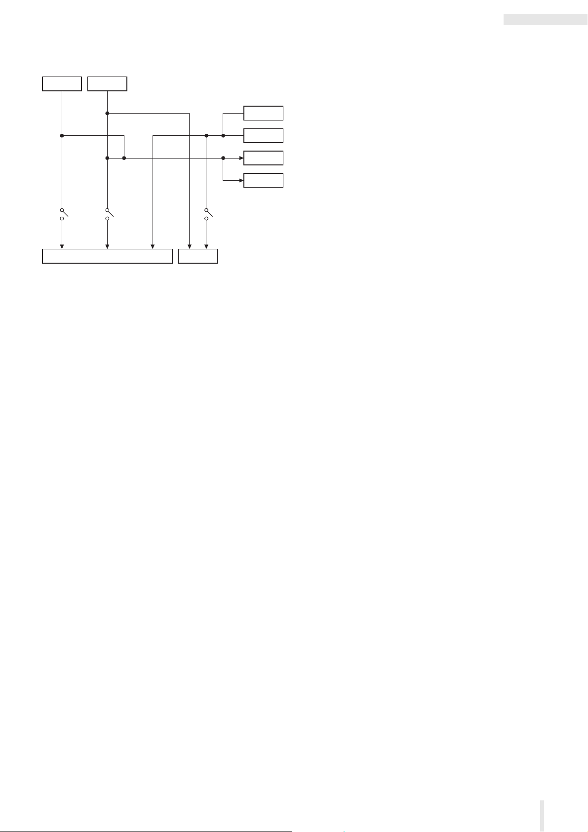
(4) SYSTEM OVERVIEW (Keyboard (KBD), Looper Play/Rec (LPR
Local
Control
LPR PLAY
TG
KBD
MIDI IN
Local
Control
LPR REC
Local
Control
USB IN
MIDI OUT
USB OUT
PLAY/REC) and Tone Generator (TG))
reface CS
reface Data List
3
Page 4
reface CS
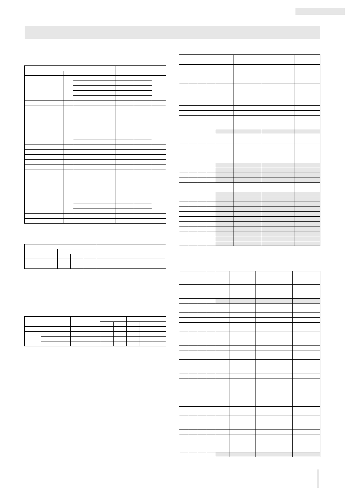
MIDI Data Table
Control Change
Transmitted and recognized Control Change Number and Value, when MIDI control is
on.
Control Change Number Control Value
Name No. Description Transmitted Recognized
LFO ASSIGN 78 OFF 0 0 – 25
AMP 32 26 – 51
FILTER 64 52 – 76
PITCH 95 77 – 102
OSC (Oscillator) 127 103 – 127
LFO DEPTH 77 — 0 – 127 0 – 127
LFO SPEED 76 — 0 – 127 0 – 127
PORTAMENTO 20 Poly 0 0
Mono with Portamento Time 1 – 127 1 – 127
OSC TYPE 80 Multi-saw 0 0 – 25
Pulse 32 26 – 51
Oscillator Sync 64 52 – 76
Ring Modulation 95 77 – 102
Frequency Modulation 127 103 – 127
OSC TEXTURE 81 — 0 – 127 0 – 127
OSC MOD (modulation) 82 — 0 – 127 0 – 127
FILTER CUTOFF 74 — 0 – 127 0 – 127
FILTER RESONANCE 71 — 0 – 127 0 – 127
EG FEG – AEG (balance) 83 — 0 – 127 0 – 127
EG A (attack time) 73 — 0 – 127 0 – 127
EG D (decay time) 75 — 0 – 127 0 – 127
EG S (sustain level ) 79 — 0 – 127 0 – 127
EG R (release time) 72 — 0 – 127 0 – 127
EFFECT TYPE 17 DIST 0 0 – 25
CHO/FLA 32 26 – 51
PHASER 64 52 – 76
DELAY 95 77 – 102
OFF (thru) 127 103 – 127
EFFECT DEPTH 18 — 0 – 127 0 – 127
EFFECT RATE 19 — 0 – 127 0 – 127
Notes
Parameter Base Address
Parameter Block
High Mid Low
SYSTEM 00 00 00
TG 30 00 00
DescriptionTop Address (hex)
Bulk Dump Block
“Top Address” indicates the top address of each block designated by bulk dump operation.
Byte Count shows the size of data in blocks from Model ID onward (up to but not
including the checksum).
To carry out TG bulk dump request, designate its corresponding BulkHeader address.
Parameter Block Description
SYSTEM Common 36 24 00 00 00
TG Bulk Header 4 04 0E 0F 00
COMMON TG Common 26 1A 30 00 00
Bulk Footer 4 04 0F 0F 00
Byte Count Top Address (hex)
Dec Hex High Mid Low
MIDI PARAMETER CHANGE TABLE (SYSTEM)
Address (hex)
High Mid Low
00 00 00 1 00 – 0F, 7F MIDI transmit
Total Size = 32
Data Range
Size
01 1 00 – 0F, 10 MIDI receive
02 4 00 – 00
06 1 00 – 01 Local Control off, ON
07 1 34 – 4C Master Transpose -12 – +12 (semitones)
08 2 00 – 02
0A 1
0B 1 00 – 01 Sustain Pedal
0C 1 00 – 01 Auto Power-Off off, ON
0D 1 00 – 01 Speaker Output off, ON
0E 1 00 – 01 MIDI Control off, ON
0F 1 28 – 58
10 1
11 1 reserved
12 1 reserved
13 1 reserved
14 1 00 – 01 Foot Volume/
15 1
16 1 reserved
17 1 reserved
18 1 reserved
19 1 reserved
1A 1 reser ved
1B 1 reser ved
1C 1 reserv ed
1D 1 reserv ed
1E 1 res erved
1F 1 reserved
Parameter Name Description Notes
(hex)
00 – 07
00 – 0F
00 – 0F
00 – 7F
channel
channel
Master Tune
Tempo MSB
Tempo LSB
reserved
Select (SUSTAIN)
Pitch Bend Range
reserved
Sustain switch
reserved
1 – 16, off
1 – 16, All
-102.4 – +102.3 (cent)
1st bit 3-0 : bit 15-12
2nd bit 3-0 : bit 11- 8
3rd bit 3-0 : bit 7- 4
4th bit 3-0 : bit 3- 0
30 – 300
1st bit 6-0 : bit 13-7
2nd bit 6-0 : bit 6-0
FC3, FC4/5
-24 – +24 (semitones)
Foot Volume, Sustain
MIDI PARAMETER CHANGE TABLE (Tone Generator)
Address (hex)
High Mid Low
30 00 00 1 00 – 7F Volume 0 – 127 This parameter
01 1
02 1 00 – 04 LFO Assign OFF, AMP, FILTER,
03 1 00 – 7F LFO Depth 0 – 127
04 1 00 – 7F LFO Speed 0 – 127
05 1 00 – 7F Portamento 0: Poly, 1 – 127: Mono
06 1 00 – 04 OSC Type
07 1 00 – 7F OSC Texture 0 – 127
08 1 00 – 7F OSC Mod
09 1 00 – 7F Filter Cutoff
0A 1 00 – 7F Filter Resonance 0 – 127
0B 1 00 – 7F EG Balance AEG max – FEG max
0C 1 00 – 7F EG A
0D 1 00 – 7F EG D
0E 1 00 – 7F EG S
0F 1 00 – 7F EG R
10 1 00 – 04 Effect Type DIST, CHO/FLA,
11 1 00 – 7F Effect Depth 0 – 127
12 1 00 – 7F Effect Rate
13 3 res erved
Total Size = 22
Size
Data
Range
Parameter Name Description Notes
(hex)
reserved
PITCH, OSC (Oscillat or)
with Portamento Time
Multi-saw, Pulse, Oscillator Sync, Ring Modulation,
Frequency Modulation
(Modulation)
Frequency
(attack time)
(decay time)
(sustain level)
(release time)
(*Note)
0 – 127
0 – 127
0 – 127
0 – 127
0 – 127
0 – 127
PHASER, DELAY,
OFF (thru)
0 – 127 DIST: tone
can be set only
via MIDI.
CHO/FLA, PHASER:
rate
DELAY: delay time
reface Data List
4
Page 5
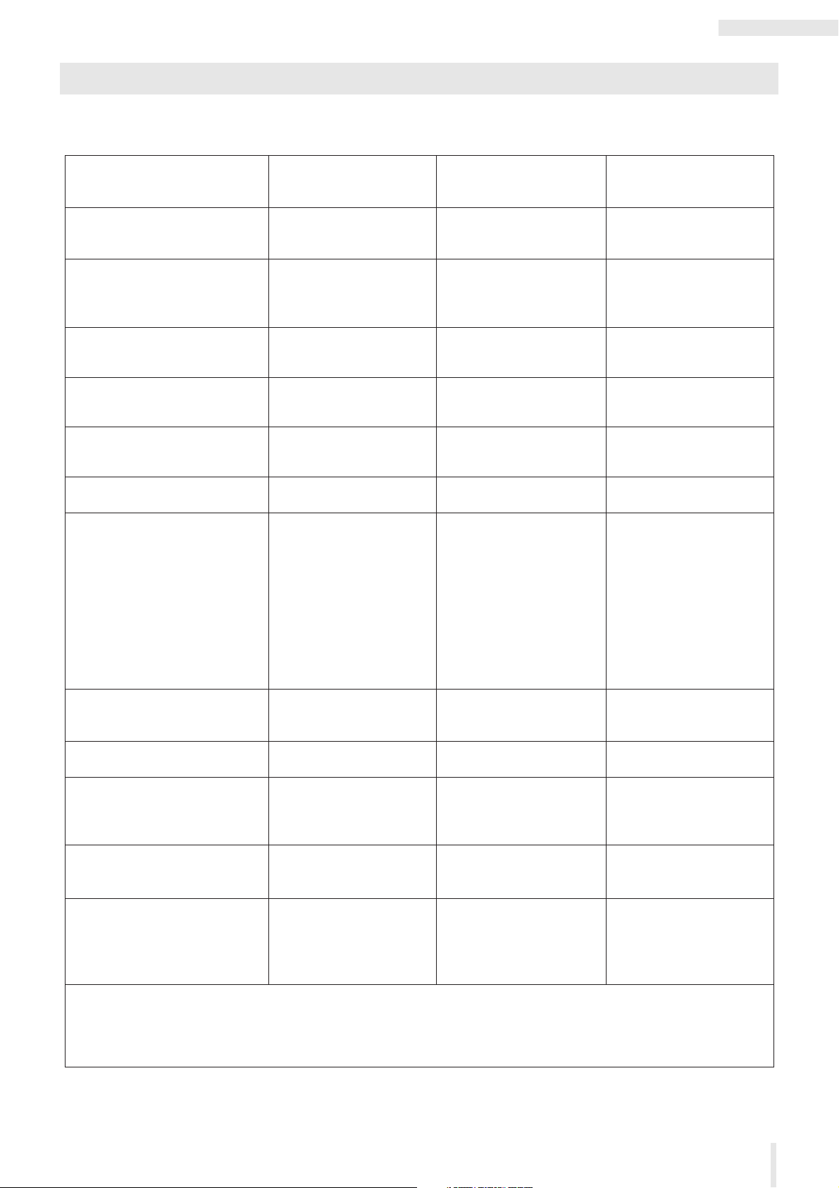
MIDI Implementation Chart
Transmitted
Function...
Recognized Remarks
Basic
Channel
Note
Number : True voice
Velocity
After
Touch
Pitch Bend
Prog
Change : True #
System Exclusive
: Song Pos.
Common : Song Sel.
: Tune
System : Clock
Real Time : Commands
: All Sound Off
Aux :
Reset All Cntrls
: Local ON/OFF
Mes- : All Notes OFF
sages: Active Sense
: Reset
Notes:*1 Transmitted and recognized if MIDI control mode is on.
*2 "m" is always treated as "1" regardless of its actual value.
*3 Transmitted if Foot Volume / Sustain switch is Foot Volume.
*4 Transmitted if Foot Volume / Sustain switch is Sustain.
Mode
Default
Changed
Note ON
Note OFF
Key's
Ch's
1
7
11
64
17-20
71-83
1
1 - 16
o 9nH,v=1-127
x 9nH,v=0
x
x
x
x
o *3
o *4
o *1
o *1
o
o
o
o
o *1
o *1
x
**************
x
x
x
o
o
x
x
x
x
o
x
3
x
**************
24 - 108
**************
o
Mode 1 : OMNI ON , POLY Mode 2 : OMNI ON ,MONO
Mode 3 : OMNI OFF, POLY Mode 4 : OMNI OFF,MONO
oo
1 - 16
1 - 16
o v=1-127
x
x
x
x
x
x
o
o
o(120,126,127)
o(121)
x
o(123-125)
o
x
1
1 - 4 (m=1) *2
x
0 - 127
0 - 127
o
o : Yes
x : No
Default
Messages
Altered
YAMAHA [ Mobile Mini Keyboard ] Date :31-MAR-2016
Model reface CS MIDI Implementation Chart Version : 1.1
Modulation Wheel
Main Volume
Expression
Sustain Sw
Transpose
x
x
Control
Change
reface CS
reface Data List
5
Page 6

reface DX
MIDI Data Format
reface DX
(1) Coverage
The specifications described herein specify transmission and reception of MIDI data of the reface DX.
(2) Compliance
The specifications described herein comply to the following standards:
• MIDI 1.0
(3) TRANSMIT/RECEIVE DATA
(3-1) CHANNEL VOICE MESSAGES
(3-1-1) NOTE OFF
STATUS 1000nnnn(8nH) n = 0 - 15 CHANNEL NUMBER
NOTE No. 0kkkkkkk k = 0 (C-2) - 127 (G8)
VELOCITY 0vvvvvvv v: ignored
Receive only
(3-1-2) NOTE ON/OFF
STATUS 1001nnnn(9nH) n = 0 - 15 CHANNEL NUMBER
NOTE NUMBER 0kkkkkkk k = 0 (C-2) - 127 (G8)
VELOCITY NOTE ON 0vvvvvvv(v≠0)
(3-1-3) CONTROL CHANGE
STATUS 1011nnnn(BnH) n = 0 - 15 CHANNEL NUMBER
CONTROL NUMBER 0ccccccc
CONTROL VALUE 0vvvvvvv
*TRANSMITTED CONTROL NUMBER
c = 64 SUSTAIN SWITCH ; v = 0 - 127 *1
*1 When Sustain is set to “FC4/5,” operating the foot switch transmits only values of 0 (off) or 127 (on).
*RECEIVED CONTROL NUMBER
c = 1 MODULATION ; v = 0 - 127
c = 7 VOLUME ; v = 0 - 127
c = 11 EXPRESSION ; v = 0 - 127
c = 64 SUSTAIN SWITCH ; v = 0 - 127
When MIDI Control Mode is turned on, Control Change numbers are assigned in order that voice parameter
changes made using controllers on the front panel can be controlled via MIDI.
See the following Control Change Table.
(3-1-4) PROGRAM CHANGE
STATUS 1100nnnn(CnH) n = 0 - 15 CHANNEL NUMBER
PROGRAM NUMBER 0ppppppp p = 0 - 31
(3-1-5) PITCH BEND CHANGE
STATUS 1110nnnn(EnH) n = 0 - 15 CHANNEL NUMBER
LSB 0vvvvvvv PITCH BEND CHANGE LSB
MSB 0vvvvvvv PITCH BEND CHANGE MSB
(3-2) CHANNEL MODE MESSAGES
STATUS 1011nnnn(BnH) n = 0 - 15 CHANNEL NUMBER
CONTROL NUMBER 0ccccccc c = CONTROL NUMBER
CONTROL VALUE 0vvvvvvv v = DATA VALUE
(3-2-1) ALL SOUND OFF (CONTROL NUMBER = 78H , DATA VALUE = 0)
All the sounds currently played including the channel messages such as note-on and hold-on in a certain channel are muted when receiving this message.
(3-2-2) RESET ALL CONTROLLERS (CONTROL NUMBER = 79H , DATA VALUE = 0)
Resets the values set for the following controllers.
PITCH BEND CHANGE 0 (center)
MODULATION 0 (minimum)
EXPRESSION 127 (maximum)
SUSTAIN SWITCH 0 (off)
(3-2-3) ALL NOTE OFF (CONTROL NUMBER = 7BH , DATA VALUE = 0)
All the notes currently set to on in c ertain channel(s) are muted when receiving this messag e.
However, if Sustain is on, notes will continue sounding un til these are turned off.
(3-2-4) OMNI MODE OFF (CONTROL NUMBER = 7CH , DATA VALUE = 0)
Performs the same function as when rece iving ALL NOTES OFF.
Sets RECEIVE CHANNEL to channel 1.
(3-2-5) OMNI MODE ON (CONTROL NUMBER = 7DH , DATA VALUE = 0)
Performs the same function as when rece iving ALL NOTES OFF.
Sets RECEIVE CHANNEL to all.
(3-2-6) MONO (CONTROL NUMBER = 7EH , DATA VALUE = 0..16)
Performs the same function as when receiving ALL SOUNDS OFF.
Sets MONO/POLY to mono-full.
(3-2-7) POLY (CONTROL NUMBER = 7FH , DATA VALUE = 0)
Performs the same function as when receiving ALL SOUNDS OFF.
Sets MONO/POLY to poly.
NOTE OFF 0vvvvvvv(v=0)
Bank1-1 … 8 0 - 7
Bank2-1 … 8 8 - 15
Bank3-1 … 8 16 - 23
Bank4-1 … 8 24 - 31
(3-3) SYSTEM REAL TIME MESSAGES
(3-3-1) ACTIVE SENSING
STATUS 11111110(FEH)
Transmitted at every 200 msec.
Once this code is received, the instrument starts sensing.
When no status nor data is received for over approximately 350 ms, M IDI receiving buffer will be cleared, and
the sounds currently played is forcibly turned off.
(3-3-2) TIMING CLOCK
STATUS 11111000(F8H)
When received via MIDI IN or USB-MIDI IN, the instrument automatically switches to external synchronization.
to the internal clock.
If no signal is received for 3 seconds, it switches back to the internal clock.
(3-3-3) START
STATUS 11111010(FAH)
(3-3-4) CONTINUE
STATUS 11111011(FBH)
Receive only
(3-3-5) STOP
STATUS 11111100(FCH)
(3-4) SYSTEM EXCLUSIVE MESSAGE
(3-4-1) UNIVERSAL NON REALTIME MESSAGE
(3-4-1-1) IDENTITY REQUEST (Receive only)
F0H 7EH 0nH 06H 01H F7H
(“n” = Device No. However, this instrument receives under “omni.”)
(3-4-1-2) IDENTITY REPLY (Transmit only)
F0H 7EH 7FH 06H 02H 43H 00H 41H 53H 06H 00H 00H 00H 7FH F7H
(3-4-2) PARAMETER CHANGE
11110000 F0H Exclusive status
01000011 43H YAMAHA ID
0001nnnn 1nH Device Number
01111111 7FH Group Number High
00011100 1CH Group Number Low
00000101 05H Model ID
0aaaaaaa aaaaaaa Address High
0aaaaaaa aaaaaaa Address Mid
0aaaaaaa aaaaaaa Address Low
0ddddddd ddddddd Data
ll
11110111 F7H End of Exclusive
For parameters with data size of 2 or more, the appropriate number of data bytes will be transmitted.
See the following MIDI Data Table for Address.
(3-4-3) BULK DUMP
11110000 F0H Exclusive status
01000011 43H YAMAHA ID
0000nnnn 0nH Device Number
01111111 7FH Group Number High
00011100 1CH Group Number Low
0bbbbbbb bbbbbbb Byte Count
0bbbbbbb bbbbbbb Byte Count
00000101 05H Model ID
0aaaaaaa aaaaaaa Address High
0aaaaaaa aaaaaaa Address Mid
0aaaaaaa aaaaaaa Address Low
0 0 Data
ll
0ccccccc ccccccc Check-sum
11110111 F7H End of Exclusive
See the following BULK DUMP Table for Address and Byte Count.
Byte Count shows the size of data in blocks from Model ID onward (up to but not including the checksum).
The Check sum is the value that results in a value of 0 for the lower 7 bits when the Model ID, Start Address,
Data and Check sum itself are added.
(3-4-4) DUMP REQUEST
11110000 F0H Exclusive status
01000011 43H YAMAHA ID
0010nnnn 2nH Device Number
01111111 7FH Group Number High
00011100 1CH Group Number Low
00000101 05H Model ID
0aaaaaaa aaaaaaa Address High
0aaaaaaa aaaaaaa Address Mid
0aaaaaaa aaaaaaa Address Low
11110111 F7H End of Exclusive
See the following DUMP REQUEST Table for Address and Byte Count.
reface Data List
6
Page 7

reface DX
Local
Control
LPR PLAY
TG
KBD
MIDI IN
Local
Control
LPR REC
Local
Control
USB IN
MIDI OUT
USB OUT
(3-4-5) PARAMETER REQUEST
11110000 F0H Exclusive status
01000011 43H YAMAHA ID
0011nnnn 3nH Device Number
01111111 7FH Group Number High
00011100 1CH Group Number Low
00000101 05H Model ID
0aaaaaaa aaaaaaa Address High
0aaaaaaa aaaaaaa Address Mid
0aaaaaaa aaaaaaa Address Low
11110111 F7H End of Exclusive
See the following MIDI Data Table for Address.
(4) SYSTEM OVERVIEW (Keyboard (KBD), Looper Play/Rec (LPR
PLAY/REC) and Tone Generator (TG))
reface Data List
7
Page 8

reface DX
MIDI Data Table
Control Change
Transmitted and recognized Control Change Number and Value, when MIDI control is
on.
Control Change Number Control Value
Name No. Description Transmitted Recognized
ALGO (algorithm) 80 ALGO 1 0 0 – 11
OP1 LEVEL (output level) 85 — 0 – 127 0 – 127
OP1 FB (feedback level) 86 — 0 – 127 0 – 127
OP1 FB (feedback type) 87 sawtooth 0 0 – 63
OP1 FREQ MODE 88 frequency/ratio (Ratio) 0 0 – 63
OP1 FREQ RATIO/FREQ
(coarse)
OP1 FREQ RATIO/FREQ
(fine)
OP2 LEVEL (output level) 102 — 0 – 127 0 – 127
OP2 FB (feedback level) 103 — 0 – 127 0 – 127
OP2 FB (feedback type) 104 sawtooth 0 0 – 63
OP2 FREQ MODE 105 frequency/ratio (Ratio) 0 0 – 63
OP2 FREQ RATIO/FREQ
(coarse)
OP2 FREQ RATIO/FREQ
(fine)
OP3 LEVEL (output level) 108 — 0 – 127 0 – 127
OP3 FB (feedback level) 109 — 0 – 127 0 – 127
OP3 FB (feedback type) 110 sawtooth 0 0 – 63
OP3 FREQ MODE 111 frequency/ratio (Ratio) 0 0 – 63
OP3 FREQ RATIO/FREQ
(coarse)
OP3 FREQ RATIO/FREQ
(fine)
OP4 LEVEL (output level) 114 — 0 – 127 0 – 127
OP4 FB (feedback level) 115 — 0 – 127 0 – 127
OP4 FB (feedback type) 116 sawtooth 0 0 – 63
OP4 FREQ MODE 117 frequency/ratio (Ratio) 0 0 – 63
OP4 FREQ RATIO/FREQ
(coarse)
OP4 FREQ RATIO/FREQ
(fine)
ALGO 2 12 12 – 21
ALGO 3 23 22 – 32
ALGO 4 35 33 – 42
ALGO 5 46 43 – 53
ALGO 6 58 54 – 64
ALGO 7 69 65 – 74
ALGO 8 81 75 – 85
ALGO 9 92 86 – 95
ALGO 10 104 96 – 106
ALGO 11 115 107 – 116
ALGO 12 127 117 – 127
square 127 64 – 127
fixed freq/Hz (Fixed) 127 64 – 127
89 — 0 – 31 0 – 31
90 — 0 – 99 0 – 99
square 127 64 – 127
fixed freq/Hz (Fixed) 127 64 – 127
106 — 0 – 31 0 – 31
107 — 0 – 99 0 – 99
square 127 64 – 127
fixed freq/Hz (Fixed) 127 64 – 127
112 — 0 – 31 0 – 31
113 — 0 – 99 0 – 99
square 127 64 – 127
fixed freq/Hz (Fixed) 127 64 – 127
118 — 0 – 31 0 – 31
119 — 0 – 99 0 – 99
Notes
Parameter Base Address
Parameter Block
High Mid Low
SYSTEM 00 00 00
VOICE COMMON 30 00 00
VOICE OPERATOR 31 op 00 op: operator number (00 – 03)
DescriptionTop Address (hex)
Bulk Dump Block
“Top Address” indicates the top address of each block designated by bulk dump operation.
Byte Count shows the size of data in blocks from Model ID onward (up to but not
including the checksum).
The Block from the Bulk Header to the Bulk Footer of the Voice can be received
regardless their order.
They can be received even if all of them are not transmitted. They cannot be received
if the irrelevant Block is included.
To carry out VOICE bulk dump request, designate its corresponding BulkHeader
address.
Parameter Block Description
SYSTEM Common 36 24 00 00 00
VOICE Bulk Header 4 04 0E 0F 00
COMMON Voice Common 42 2A 30 00 00
Operator Operator 1
:
Operator 4
Bulk Footer 4 04 0F 0F 00
Byte Count Top Address (hex)
Dec Hex High Mid Low
32 20 31 00
:
03
00
MIDI PARAMETER CHANGE TABLE (SYSTEM)
Address (hex)
High Mid Low
00 00 00 1 00 – 0F, 7F MIDI transmit
01 1 00 – 0F, 10 MIDI receive
02 4 00 – 00
06 1 00 – 01 Local Control
07 1 34 – 4C Master Transpose -12 – +12 (semitones)
08 2 00 – 02
0A 1 00 – 3F LCD Contrast
0B 1 00 – 01 Sustain Pedal
0C 1 00 – 01 Auto Power-Off
0D 1 00 – 01 Speaker Output
0E 1 00 – 01 MIDI Control
0F 1
10 1 reserved
11 1 reserved
12 1 reserved
13 1 reserved
14 1 reserved
15 1 reserved
16 1 reserved
17 1 reserved
18 1 reserved
19 1 reserved
1A 1 reserved
1B 1 reserved
1C 1 reserved
1D 1 reserved
1E 1 reserv ed
1F 1 reserved
Total Size = 32
Size
Data Range
(hex)
00 – 07
00 – 0F
00 – 0F
00 – 7F
Parameter Name Descriptio n Notes
channel (TR CH)
channel (RV CH)
Master Tune -102.4 – +102.3 (cent)
(CONTROL)
Tempo MSB
Tempo LSB
(CONTRAST)
Select (SUSTAIN)
(AUTO P.OFF)
(SP)
(CONTROL)
reserved
1 – 16, off
1 – 16, All
1st bit 3-0 : bit 15- 12
2nd bit 3-0 : bit 11- 8
3rd bit 3-0 : bit 7- 4
4th bit 3-0 : bit 3- 0
off, ON
30 – 300
1st bit 6-0 : bit 13-7
2nd bit 6-0 : bit 6-0
0 – 63
FC3, FC4/5
off, ON
off, ON
off, ON
reface Data List
8
Page 9

reface DX
MIDI PARAMETER CHANGE TABLE
(VOICE Common)
Address (hex)
High Mid Low
30 00 00 1 20 – 7E Voice Name1 32 – 126 (ASCII)
01 1 20 – 7E Voice Name2 32 – 126 (ASCII)
02 1 20 – 7E Voice Name3 32 – 126 (ASCII)
03 1 20 – 7E Voice Name4 32 – 126 (ASCII)
04 1 20 – 7E Voice Name5 32 – 126 (ASCII)
05 1 20 – 7E Voice Name6 32 – 126 (ASCII)
06 1 20 – 7E Voice Name7 32 – 126 (ASCII)
07 1 20 – 7E Voice Name8 32 – 126 (ASCII)
08 1 20 – 7E Voice Name9 32 – 126 (ASCII)
09 1 20 – 7E Voice Name10 32 – 126 (ASCII)
0A 1
0B 1 reserved
0C 1 28 – 58 Transpose (TP)
0D 1 00 – 02 Part Mode poly (POLY), Mono-
0E 1 00 – 7F Portamento
0F 1 28 – 58 Pitch Bend
10 1 00 – 0B
11 1 00 – 06 LFO Wave
12 1 00 – 7F LFO Speed
13 1 00 – 7F LFO Delay
14 1 00 – 7F LFO Pitch Modu-
15 1 00 – 7F Pitch EG Rate 1
16 1 00 – 7F Pitch EG Rate 2
17 1 00 – 7F Pitch EG Rate 3
18 1 00 – 7F Pitch EG Rate 4
19 1 10 – 70 Pitch EG Level 1
1A 1 10 – 70 Pitch EG Level 2
1B 1 10 – 70 Pitch EG Level 3
1C 1 10 – 70 Pitch EG Level 4
1D 1 00 – 07 Effect 1 Type thru (THRU),
1E 1 00 – 7F Effect 1 Parame-
1F 1 00 – 7F Effect 1 Parame-
20 1 00 – 07 Effect 2 Type thru (THRU),
21 1 00 – 7F Effect 2 Parame-
22 1 00 – 7F Effect 2 Parame-
23 3
Total Size = 38
Size
Data
Range
Parameter Name Description Notes
(hex)
reserved
-24 – +24 (semitones)
Full (MONO-FULL),
Mono-Legato
(MONO-LGATO)
Time (PORTA)
Range (PB)
Algorithm (ALGO)
(WAVE)
(SPEED)
(DELAY)
lation Depth
(PMD)
(PITCH EG Rate)
(PITCH EG Rate)
(PITCH EG Rate)
(PITCH EG Rate)
(PITCH EG Level)
(PITCH EG Level)
(PITCH EG Level)
(PITCH EG Level)
ter 1 (*Note)
ter 2 (*Note)
ter 1 (*Note)
ter 2 (*Note)
reserved
-24 – +24
(semitones)
ALGO 1 – 12
sine (SIN),
triangle (TRI),
sawtooth up (SAW U),
sawtooth down (SAW D),
square (SQ),
sample & hold 8 (S&H8),
sample & hold (S&H)
0 – 127
0 – 127
0 (no LFO) –
127 (max)
0 (slow) – 127 (fast)
0 (slow) – 127 (fast)
0 (slow) – 127 (fast)
0 (slow) – 127 (fast)
-48 (-4 octave) –
+48 (+4 octave)
-48 (-4 octave) –
+48 (+4 octave)
-48 (-4 octave) –
+48 (+4 octave)
-48 (-4 octave) –
+48 (+4 octave)
distortion (DIST),
touch wah (T.WAH),
chorus (CHO),
flanger (FLA),
phaser (PHA),
delay (DLY),
reverb (REV)
0 – 127 DRIVE: distortion
0 – 127 TONE: distortion
distortion (DIST),
touch wah (T.WAH),
chorus (CHO),
flanger (FLA),
phaser (PHA),
delay (DLY),
reverb (REV)
0 – 127 DRIVE: distortion
0 – 127 TONE: distortion
MONO-FULL:
applied to all notes
MONO-LGATO:
applied only to
notes played legato
SENS: touch wah
DEPTH: chorus,
flanger, phaser,
delay, reverb
REZ: touch wah
RATE: chorus,
flanger, phaser
TIME: delay, reverb
SENS: touch wah
DEPTH: chorus,
flanger, phaser,
delay, reverb
REZ: touch wah
RATE: chorus,
flanger, phaser
TIME: delay, reverb
MIDI PARAMETER CHANGE TABLE (Operator)
op = operator number
00 – 03 (hex)
OP1 – OP4
Address (hex)
High Mid Low
31 op 00 1 00 – 01 OP ON-OFF (OP) off, ON
op 01 1 00 – 7F OP EG Rate 1 0 (slow) – 127 (fast)
op 02 1 00 – 7F OP EG Rate 2 0 (slow) – 127 (fast)
op 03 1 00 – 7F OP EG Rate 3 0 (slow) – 127 (fast)
op 04 1 00 – 7F OP EG Rate 4 0 (slow) – 127 (fast)
op 05 1 00 – 7F OP EG Level 1 0 (no output) –
op 06 1 00 – 7F OP EG Level 2 0 (no output) –
op 07 1 00 – 7F OP EG Level 3 0 (no output) –
op 08 1 00 – 7F OP EG Level 4 0 (no output) –
op 09 1 00 – 7F OP EG Keyboard
op 0A 1 00 – 7F OP Keyboard Level
op 0B 1 00 – 7F OP Keyboard Level
op 0C 1 00 – 03 OP Keyboard Level
op 0D 1 00 – 03 OP Keyboard Level
op 0E 1 00 – 7F OP LFO AMD Depth
op 0F 1 00 – 01 OP LFO PMD ON/
op 10 1 00 – 01 OP PEG ON/OFF
op 11 1 00 – 7F OP Level Velocity
op 12 1 00 – 7F OP Level Output
op 13 1 00 – 7F OP Level Feedback
op 14 1 00 – 01 OP Level Feedback
op 15 1 00 – 01 OP Freq. Mode
op 16 1 00 – 1F OP Freq. Coarse
op 17 1 00 – 63 OP Freq. Fine
op 18 1 00 – 7F OP Freq, Detune
op 19 3
Total Size = 28
Size
Data
Range
Parameter Name Description Notes
(hex)
127 (max)
127 (max)
127 (max)
127 (max)
Rate Scaling
(KSC-R)
Scaling Left Depth
(KSC-Level)
Scaling Right Depth
(KSC-Level)
Scaling Left Curve
(KSC-Level)
Scaling Right Curve
(KSC-Level)
(LFO AMD)
OFF (LFO PMD On/
Off)
(PITCH EG On/Off)
Sensitivity (VEL.S)
Level (LEVEL)
Level (FB)
Type (FB)
(MODE)
(RATIO/FREQ)
(RATIO/FREQ)
(DTUNE)
reserved
0 – 127
0 (flat: no variation) –
127 (max)
0 (flat: no variation) –
127 (max)
-linear (-LIN),
-exponential (-EXP),
+exponential (+EXP),
+linear (+LIN)
-linear (-LIN),
-exponential (-EXP),
+exponential (+EXP),
+linear (+LIN)
0 (no amplitude) –
127 (max)
off, ON
off, ON
0 (no touch response) –
127 (max)
0 – 127
0 – 127
sawtooth, square
frequency/ratio (Ratio),
fixed freq/Hz (Fixed)
-64 – +63
Program Change Number
Program No. Description Notes
0 – 7 Bank 1-1 – 1-8
8 – 15 Bank 2-1 – 2-8
16 – 23 Bank 3-1 – 3-8
24 – 31 Bank 4-1 – 4-8
reface Data List
9
Page 10

MIDI Implementation Chart
Transmitted
Function...
Recognized Remarks
Basic
Channel
Note
Number : True voice
Velocity
After
Touch
Pitch Bend
Prog
Change : True #
System Exclusive
: Song Pos.
Common : Song Sel.
: Tune
System : Clock
Real Time : Commands
: All Sound Off
Aux :
Reset All Cntrls
: Local ON/OFF
Mes- : All Notes OFF
sages: Active Sense
: Reset
Notes:*1 Transmitted and recognized if MIDI control mode is on.
*2 "m" is always treated as "1" regardless of its actual value.
Mode
Default
Changed
Note ON
Note OFF
Key's
Ch's
1
7
11
64
80,85-90
102-119
1
1 - 16
o 9nH,v=1-127
x 9nH,v=0
x
x
x
x
x
o
o *1
o *1
o
o
o
o
o *1
o *1
o 0 - 31
**************
x
x
x
o
o
x
x
x
x
o
x
3
x
**************
24 - 108
**************
o
Mode 1 : OMNI ON , POLY Mode 2 : OMNI ON ,MONO
Mode 3 : OMNI OFF, POLY Mode 4 : OMNI OFF,MONO
oo
1 - 16
1 - 16
o v=1-127
x
x
x
x
x
x
o
o
o(120,126,127)
o(121)
x
o(123-125)
o
x
1
1 - 4 (m=1) *2
x
0 - 127
0 - 127
o
o : Yes
x : No
Default
Messages
Altered
YAMAHA [ Mobile Mini Keyboard ] Date :20-FEB-2015
Model reface DX MIDI Implementation Chart Version : 1.0
Modulation Wheel
Main Volume
Expression
Sustain Sw
Transpose
Memorized
o 0 - 31
0 - 31
Control
Change
reface DX
reface Data List
10
Page 11

reface CP
MIDI Data Format
reface CP
(1) Coverage
The specifications described herein specify transmission and reception of MIDI data of the reface CP.
(2) Compliance
The specifications described herein comply to the following standards:
• MIDI 1.0
(3) TRANSMIT/RECEIVE DATA
(3-1) CHANNEL VOICE MESSAGES
(3-1-1) NOTE OFF
STATUS 1000nnnn(8nH) n = 0 - 15 CHANNEL NUMBER
NOTE No. 0kkkkkkk k = 0 (C-2) - 127 (G8)
VELOCITY 0vvvvvvv v: ignored
Receive only
(3-1-2) NOTE ON/OFF
STATUS 1001nnnn(9nH) n = 0 - 15 CHANNEL NUMBER
NOTE NUMBER 0kkkkkkk k = 0 (C-2) - 127 (G8)
VELOCITY NOTE ON 0vvvvvvv(v≠0)
(3-1-3) CONTROL CHANGE
STATUS 1011nnnn(BnH) n = 0 - 15 CHANNEL NUMBER
CONTROL NUMBER 0ccccccc
CONTROL VALUE 0vvvvvvv
*TRANSMITTED CONTROL NUMBER
c = 64 SUSTAIN SWITCH ; v = 0 - 127 *1
*1 When Sustain is set to “FC4/5,” operating the foot switch transmits only values of 0 (off) or 127 (on).
*RECEIVED CONTROL NUMBER
c = 1 MODULATION ; v = 0 - 127
c = 7 VOLUME ; v = 0 - 127
c = 11 EXPRESSION ; v = 0 - 127
c = 64 SUSTAIN SWITCH ; v = 0 - 127
c = 66 SOSTENUTO ; v = 0-63:OFF , 64-127:ON
c = 67 SOFT PEDAL ; v = 0-63:OFF , 64-127:ON
When MIDI Control Mode is turned on, Control Change numbers are assigned in order that voice parameter
changes made using controllers on the front panel can be controlled via MIDI.
See the following Control Change Table.
(3-1-4) PITCH BEND CHANGE (Receive only)
STATUS 1110nnnn(EnH) n = 0 - 15 CHANNEL NUMBER
LSB 0vvvvvvv PITCH BEND CHANGE LSB
MSB 0vvvvvvv PITCH BEND CHANGE MSB
(3-2) CHANNEL MODE MESSAGES
STATUS 1011nnnn(BnH) n = 0 - 15 CHANNEL NUMBER
CONTROL NUMBER 0ccccccc c = CONTROL NUMBER
CONTROL VALUE 0vvvvvvv v = DATA VALUE
(3-2-1) ALL SOUND OFF (CONTROL NUMBER = 78H , DATA VALUE = 0)
All the sounds currently played including the channel messages such as note-on and hold-on in a certain channel are muted when receiving this message.
(3-2-2) RESET ALL CONTROLLERS(CONTROL NUMBER = 79H , DATA VALUE = 0)
Resets the values set for the following controllers.
PITCH BEND CHANGE 0 (center)
MODULATION 0 (minimum)
EXPRESSION 127 (maximum)
SUSTAIN SWITCH 0 (off)
SOSTENUTO SWITCH 0 (off)
SOFT PEDAL 0 (off)
(3-2-3) ALL NOTE OFF(CONTROL NUMBER = 7BH , DATA VALUE = 0)
All the notes currently set to on in c ertain channel(s) are muted when receiving this messag e.
However, if Sustain or Sostenuto is on, notes will continue soundi ng until these are turned off.
(3-2-4) OMNI MODE OFF (CONTROL NUMBER = 7CH , DATA VALUE = 0)
Performs the same function as when rece iving ALL NOTES OFF.
Sets RECEIVE CHANNEL to channel 1.
(3-2-5) OMNI MODE ON (CONTROL NUMBER = 7DH , DATA VALUE = 0)
Performs the same function as when rece iving ALL NOTES OFF.
Sets RECEIVE CHANNEL to all.
(3-2-6) MONO (CONTROL NUMBER = 7EH , DATA VALUE = 0..16)
Performs the same function as when receiving ALL SOUNDS OFF.
(3-2-7) POLY (CONTROL NUMBER = 7FH , DATA VALUE = 0)
Performs the same function as when receiving ALL SOUNDS OFF.
NOTE OFF 0vvvvvvv(v=0)
(3-3) SYSTEM REAL TIME MESSAGES
(3-3-1) ACTIVE SENSING
STATUS 11111110(FEH)
Transmitted at every 200 msec.
Once this code is received, the instrument starts sensing.
When no status nor data is received for over approximately 350 ms, M IDI receiving buffer will be cleared, and
the sounds currently played is forcibly turned off.
(3-4) SYSTEM EXCLUSIVE MESSAGE
(3-4-1) UNIVERSAL NON REALTIME MESSAGE
(3-4-1-1) IDENTITY REQUEST (Receive only)
F0H 7EH 0nH 06H 01H F7H
(“n” = Device No. However, this instrument receives under “omni.”)
(3-4-1-2) IDENTITY REPLY (Transmit only)
F0H 7EH 7FH 06H 02H 43H 00H 41H 52H 06H 00H 00H 00H 7FH F7H
(3-4-2) PARAMETER CHANGE
11110000 F0H Exclusive status
01000011 43H YAMAHA ID
0001nnnn 1nH Device Number
01111111 7FH Group Number High
00011100 1CH Group Number Low
00000100 04H Model ID
0aaaaaaa aaaaaaa Address High
0aaaaaaa aaaaaaa Address Mid
0aaaaaaa aaaaaaa Address Low
0ddddddd ddddddd Data
ll
11110111 F7H End of Exclusive
For parameters with data size of 2 or more, the appropriate number of data bytes will be transmitted.
See the following MIDI Data Table for Address.
(3-4-3) BULK DUMP
11110000 F0H Exclusive status
01000011 43H YAMAHA ID
0000nnnn 0nH Device Number
01111111 7FH Group Number High
00011100 1CH Group Number Low
0bbbbbbb bbbbbbb Byte Count
0bbbbbbb bbbbbbb Byte Count
00000100 04H Model ID
0aaaaaaa aaaaaaa Address High
0aaaaaaa aaaaaaa Address Mid
0aaaaaaa aaaaaaa Address Low
0 0 Data
ll
0ccccccc ccccccc Check-sum
11110111 F7H End of Exclusive
See the following BULK DUMP Table for Address and Byte Count.
Byte Count shows the size of data in blocks from Model ID onward (up to but not including the checksum).
The Check sum is the value that results in a value of 0 for the lower 7 bits when the Model ID, Start Address,
Data and Check sum itself are added.
(3-4-4) DUMP REQUEST
11110000 F0H Exclusive status
01000011 43H YAMAHA ID
0010nnnn 2nH Device Number
01111111 7FH Group Number High
00011100 1CH Group Number Low
00000100 04H Model ID
0aaaaaaa aaaaaaa Address High
0aaaaaaa aaaaaaa Address Mid
0aaaaaaa aaaaaaa Address Low
11110111 F7H End of Exclusive
See the following DUMP REQUEST Table for Address and Byte Count.
(3-4-5) PARAMETER REQUEST
11110000 F0H Exclusive status
01000011 43H YAMAHA ID
0011nnnn 3nH Device Number
01111111 7FH Group Number High
00011100 1CH Group Number Low
00000100 04H Model ID
0aaaaaaa aaaaaaa Address High
0aaaaaaa aaaaaaa Address Mid
0aaaaaaa aaaaaaa Address Low
11110111 F7H End of Exclusive
See the following MIDI Data Table for Address.
reface Data List
11
Page 12

(4) SYSTEM OVERVIEW (Keyboard (KBD), and
Local
TG
KBD
MIDI IN
USB IN
MIDI OUT
USB OUT
Control
Tone Generator (TG))
reface CP
reface Data List
12
Page 13

reface CP
MIDI Data Table
Control Change
Transmitted and recognized Control Change Number and Value, when MIDI control is
on.
Control Change Number Control Value
Name No. Description Transmitted Recognized
TYPE 80 Rd I 00 – 21
DRIVE 81 — 0 – 127 0 – 127
TREMOLO/WAH SWITCH 17 OFF 0 0 – 42
TREMOLO/WAH DEPTH 18 — 0 – 127 0 – 127
TREMOLO/WAH RATE 19 — 0 – 127 0 – 127
CHORUS/PHASER
SWITCH
CHORUS/PHASER
DEPTH
CHORUS/PHASER
SPEED
D.DELAY/A.DELAY
SWITCH
D.DELAY/A.DELAY
DEPTH
D.DELAY/A.DELAY TIME 90 — 0 – 127 0 – 127
REVERB DEPTH 91 — 0 – 127 0 – 127
Rd II 25 22 – 42
Wr 51 43 – 64
Clv 76 65 – 85
Toy 102 86 – 106
CP 127 107 – 127
TREMOLO 64 43 – 85
WAH 127 86 – 127
85 OFF 0 0 – 42
CHORUS 64 43 – 85
PHASER 127 86 – 127
86 — 0 – 127 0 – 127
87 — 0 – 127 0 – 127
88 OFF 0 0 – 42
D.DELAY 64 43 – 85
A.DELAY 127 86 – 127
89 — 0 – 127 0 – 127
Notes
Parameter Base Address
Parameter Block
High Mid Low
SYSTEM 00 00 00
TG 30 00 00
DescriptionTop Address (hex)
MIDI PARAMETER CHANGE TABLE (SYSTEM)
Address (hex)
High Mid Low
00 00 00 1 00 – 0F, 7F MIDI transmit
01 1 00 – 0F, 10 MIDI receive
02 4 00 – 00
06 1 00 – 01 Local Control off, ON
07 1 34 – 4C Master Trans-
08 1
09 1 res erved
0A 1 reserve d
0B 1 00 – 01 Sustain Pedal
0C 1 00 – 01 Auto Power-Off off, ON
0D 1 00 – 01 Speaker Output off, ON
0E 1 00 – 01 MIDI Control off, ON
0F 1
10 1 res erved
11 1 res erved
12 1 res erved
13 1 res erved
14 1 res erved
15 1 res erved
16 1 res erved
17 1 res erved
18 1 res erved
19 1 res erved
1A 1 reserve d
1B 1 reserve d
1C 1 reserved
1D 1 reserved
1E 1 reserv ed
1F 1 res erved
Total Size = 32
Size
Data Range
(hex)
00 – 07
00 – 0F
00 – 0F
Parameter Name Description Notes
channel
channel
Master Tune -102.4 – +102.3 (cent)
pose
reser ved
Select
reser ved
1 – 16, off
1 – 16, All
1st bit 3-0 : bit 15- 12
2nd bit 3-0 : bit 11- 8
3rd bit 3-0 : bit 7- 4
4th bit 3-0 : bit 3- 0
-12 – +12 (semitones)
FC3, FC4/5
Bulk Dump Block
“Top Address” indicates the top address of each block designated by bulk dump operation.
Byte Count shows the size of data in blocks from Model ID onward (up to but not
including the checksum).
To carry out TG bulk dump request, designate its corresponding BulkHeader address.
Parameter Block Description
SYSTEM Common 36 24 00 00 00
TG Bulk Header 4 04 0E 0F 00
COMMON TG Common 20 14 30 00 00
Bulk Footer 4 04 0F 0F 00
Byte Count Top Address (hex)
Dec Hex High Mid Low
MIDI PARAMETER CHANGE TABLE
(Tone Generator)
Address (hex)
High Mid Low
30 00 00 1 00 – 7F Volume 0 – 127 This parameter can
01 1
02 1 00 – 05 Wave Type
03 1 00 – 7F Drive (DRIVE) 0 – 127
04 1 00 – 02 Effect 1 Type
05 1 00 – 7F Effect 1 Depth
06 1 00 – 7F Effect 1 Rate
07 1 00 – 02 Effect 2 Type
08 1 00 – 7F Effect 2 Depth
09 1 00 – 7F Effect 2
0A 1 00 – 02 Effect 3 Type
0B 1 00 – 7F Effect 3 Depth
0C 1 00 – 7F Effect 3 Time
0D 1 00 – 7F Reverb Depth
0E 2
Total Size = 16
Size
Data
Range
(hex)
Parameter
Name
reserved
(TYPE)
(TREMOLO/
WAH)
(DEPTH)
(RATE)
(CHORUS/
PHASER)
(DEPTH)
Speed
(SPEED)
(D.DELAY/
A.DELAY)
(DEPTH)
(TIME)
(REVERB
DEPTH)
reserved
Description Notes
be set only via MIDI.
Rd I, Rd II, Wr, Clv, Toy,
CP
thru (middle position),
tremolo (TREMOLO),
wah (WAH)
0 – 127 Rd I, Rd II, CP:
0 – 127 TREMOLO: speed of
thru (middle position),
chorus (CHORUS),
phaser (PHASER)
0 – 127
0 – 127
thru (middle potision),
Digital Delay (D.DELAY),
Analog Delay (A.DELAY)
0 – 127
0 – 127
0 – 127
sound is modulated left and right
Wr, Clv, Toy: volume
is modulated
modulation
WAH: resonance off-
set value
reface Data List
13
Page 14

MIDI Implementation Chart
Transmitted
Function...
Recognized Remarks
Basic
Channel
Note
Number : True voice
Velocity
After
Touch
Pitch Bend
Prog
Change : True #
System Exclusive
: Song Pos.
Common : Song Sel.
: Tune
System : Clock
Real Time : Commands
: All Sound Off
Aux :
Reset All Cntrls
: Local ON/OFF
Mes- : All Notes OFF
sages: Active Sense
: Reset
Notes:*1 Transmitted and recognized if MIDI control mode is on.
Mode
Default
Changed
Note ON
Note OFF
Key's
Ch's
1
7
11
64
66,67
17-19
80,81
85-91
1
1 - 16
o 9nH,v=1-127
x 9nH,v=0
x
x
x
x
x
o
x
o *1
o *1
o *1
o
o
o
o
o
o *1
o *1
o *1
x
**************
x
x
x
x
x
x
x
x
x
o
x
3
x
**************
24 - 108
**************
o
Mode 1 : OMNI ON , POLY Mode 2 : OMNI ON ,MONO
Mode 3 : OMNI OFF, POLY Mode 4 : OMNI OFF,MONO
xo
1 - 16
1 - 16
o v=1-127
x
x
x
x
x
x
x
x
o(120,126,127)
o(121)
x
o(123-125)
o
x
1
1,3
x
0 - 127
0 - 127
o
o : Yes
x : No
Default
Messages
Altered
YAMAHA [ Mobile Mini Keyboard ] Date :23-MAR-2015
Model reface CP MIDI Implementation Chart Version : 1.0
Modulation Wheel
Main Volume
Expression
Sustain Sw
Transpose
x
x
Control
Change
reface CP
reface Data List
14
Page 15

reface YC
MIDI Data Format
reface YC
(1) Coverage
The specifications described herein specify transmission and reception of MIDI data of the reface YC.
(2) Compliance
The specifications described herein comply to the following standards:
• MIDI 1.0
(3) TRANSMIT/RECEIVE DATA
(3-1) CHANNEL VOICE MESSAGES
(3-1-1) NOTE OFF
STATUS 1000nnnn(8nH) n = 0 - 15 CHANNEL NUMBER
NOTE No. 0kkkkkkk k = 0 (C-2) - 127 (G8)
VELOCITY 0vvvvvvv v: ignored
Receive only
(3-1-2) NOTE ON/OFF
STATUS 1001nnnn(9nH) n = 0 - 15 CHANNEL NUMBER
NOTE NUMBER 0kkkkkkk k = 0 (C-2) - 127 (G8)
VELOCITY NOTE ON 0vvvvvvv(v≠0)
(3-1-3) CONTROL CHANGE
STATUS 1011nnnn(BnH) n = 0 - 15 CHANNEL NUMBER
CONTROL NUMBER 0ccccccc
CONTROL VALUE 0vvvvvvv
*TRANSMITTED CONTROL NUMBER
c = 11 EXPRESSION ; v = 0 - 127
*RECEIVED CONTROL NUMBER
c = 1 MODULATION ; v = 0 - 127
c = 7 VOLUME ; v = 0 - 127
c = 11 EXPRESSION ; v = 0 - 127
c = 64 SUSTAIN SWITCH ; v = 0 - 127
When MIDI Control Mode is turned on, Control Change numbers are assigned in order that voice parameter
changes made using controllers on the front panel can be controlled via MIDI.
See the following Control Change Table.
(3-1-4) PITCH BEND CHANGE (Receive only)
STATUS 1110nnnn(EnH) n = 0 - 15 CHANNEL NUMBER
LSB 0vvvvvvv PITCH BEND CHANGE LSB
MSB 0vvvvvvv PITCH BEND CHANGE MSB
(3-2) CHANNEL MODE MESSAGES
STATUS 1011nnnn(BnH) n = 0 - 15 CHANNEL NUMBER
CONTROL NUMBER 0ccccccc c = CONTROL NUMBER
CONTROL VALUE 0vvvvvvv v = DATA VALUE
(3-2-1) ALL SOUND OFF (CONTROL NUMBER = 78H , DATA VALUE = 0)
All the sounds currently played including the channel messages such as note-on and hold-on in a certain channel are muted when receiving this message.
(3-2-2) RESET ALL CONTROLLERS (CONTROL NUMBER = 79H , DATA VALUE = 0)
Resets the values set for the following controllers.
PITCH BEND CHANGE 0 (center)
MODULATION 0 (minimum)
EXPRESSION 127 (maximum)
SUSTAIN SWITCH 0 (off)
(3-2-3) ALL NOTE OFF (CONTROL NUMBER = 7BH , DATA VALUE = 0)
All the notes currently set to on in c ertain channel(s) are muted when receiving this messag e.
However, if Sustain is on, notes will continue sounding un til these are turned off.
(3-2-4) OMNI MODE OFF (CONTROL NUMBER = 7CH , DATA VALUE = 0)
Performs the same function as when rece iving ALL NOTES OFF.
Sets RECEIVE CHANNEL to channel 1.
(3-2-5) OMNI MODE ON (CONTROL NUMBER = 7DH , DATA VALUE = 0)
Performs the same function as when rece iving ALL NOTES OFF.
Sets RECEIVE CHANNEL to all.
(3-2-6) MONO (CONTROL NUMBER = 7EH , DATA VALUE = 0..16)
Performs the same function as when receiving ALL SOUNDS OFF.
(3-2-7) POLY (CONTROL NUMBER = 7FH , DATA VALUE = 0)
Performs the same function as when receiving ALL SOUNDS OFF.
NOTE OFF 0vvvvvvv(v=0)
(3-3) SYSTEM REAL TIME MESSAGES
(3-3-1) ACTIVE SENSING
STATUS 11111110(FEH)
Transmitted at every 200 msec.
Once this code is received, the instrument starts sensing.
When no status nor data is received for over approximately 350 ms, M IDI receiving buffer will be cleared, and
the sounds currently played is forcibly turned off.
(3-4) SYSTEM EXCLUSIVE MESSAGE
(3-4-1) UNIVERSAL NON REALTIME MESSAGE
(3-4-1-1) IDENTITY REQUEST (Receive only)
F0H 7EH 0nH 06H 01H F7H
(“n” = Device No. However, this instrument receives under “omni.”)
(3-4-1-2) IDENTITY REPLY (Transmit only)
F0H 7EH 7FH 06H 02H 43H 00H 41H 54H 06H 00H 00H 00H 7FH F7H
(3-4-2) PARAMETER CHANGE
11110000 F0H Exclusive status
01000011 43H YAMAHA ID
0001nnnn 1nH Device Number
01111111 7FH Group Number High
00011100 1CH Group Number Low
00000110 06H Model ID
0aaaaaaa aaaaaaa Address High
0aaaaaaa aaaaaaa Address Mid
0aaaaaaa aaaaaaa Address Low
0ddddddd ddddddd Data
ll
11110111 F7H End of Exclusive
For parameters with data size of 2 or more, the appropriate number of data bytes will be transmitted.
See the following MIDI Data Table for Address.
(3-4-3) BULK DUMP
11110000 F0H Exclusive status
01000011 43H YAMAHA ID
0000nnnn 0nH Device Number
01111111 7FH Group Number High
00011100 1CH Group Number Low
0bbbbbbb bbbbbbb Byte Count
0bbbbbbb bbbbbbb Byte Count
00000110 06H Model ID
0aaaaaaa aaaaaaa Address High
0aaaaaaa aaaaaaa Address Mid
0aaaaaaa aaaaaaa Address Low
0 0 Data
ll
0ccccccc ccccccc Check-sum
11110111 F7H End of Exclusive
See the following BULK DUMP Table for Address and Byte Count.
Byte Count shows the size of data in blocks from Model ID onward (up to but not including the checksum).
The Check sum is the value that results in a value of 0 for the lower 7 bits when the Model ID, Start Address,
Data and Check sum itself are added.
(3-4-4) DUMP REQUEST
11110000 F0H Exclusive status
01000011 43H YAMAHA ID
0010nnnn 2nH Device Number
01111111 7FH Group Number High
00011100 1CH Group Number Low
00000110 06H Model ID
0aaaaaaa aaaaaaa Address High
0aaaaaaa aaaaaaa Address Mid
0aaaaaaa aaaaaaa Address Low
11110111 F7H End of Exclusive
See the following DUMP REQUEST Table for Address and Byte Count.
(3-4-5) PARAMETER REQUEST
11110000 F0H Exclusive status
01000011 43H YAMAHA ID
0011nnnn 3nH Device Number
01111111 7FH Group Number High
00011100 1CH Group Number Low
00000110 06H Model ID
0aaaaaaa aaaaaaa Address High
0aaaaaaa aaaaaaa Address Mid
0aaaaaaa aaaaaaa Address Low
11110111 F7H End of Exclusive
See the following MIDI Data Table for Address.
reface Data List
15
Page 16

(4) SYSTEM OVERVIEW (Keyboard (KBD), and
Local
TG
KBD
MIDI IN
USB IN
MIDI OUT
USB OUT
Control
Tone Generator (TG))
reface YC
reface Data List
16
Page 17

reface YC
MIDI Data Table
Control Change
Transmitted and recognized Control Change Number and Value, when MIDI control is
on.
Control Change Number Control Value
Name No. Description Transmitted Recognized
ROTARY SPEED 19 O FF 0 0 – 32
WAVE 80 H 0 0 – 25
FOOTAGE 16' 102 FOOTAGE Slider 0
FOOTAGE 5 1/3' 103 FOOTAGE Slider 0
FOOTAGE 8' 104 FOOTAGE Slider 0
FOOTAGE 4' 105 FOOTAGE Slider 0
FOOTAGE 2 2/3' 106 FOOTAGE Slider 0
FOOTAGE 2' 107 FOOTAGE Slider 0
FOOTAGE 1 3/5' 108 FOOTAGE Slider 0
FOOTAGE 1 1/3' 109 FOOTAGE Slider 0
STOP 42 33 – 64
SLOW 85 65 – 95
FAST 127 96 – 127
V 32 26 – 51
F 64 52 – 76
A 95 77 – 102
Y 127 103 – 127
(Minimum: up)
FOOTAGE Slider 1 21 19 – 36
FOOTAGE Slider 2 42 37 – 54
FOOTAGE Slider 3 64 55 – 73
FOOTAGE Slider 4 85 74 – 91
FOOTAGE Slider 5 106 92 – 109
FOOTAGE Slider 6
(Maximum)
(Minimum: up)
FOOTAGE Slider 1 21 19 – 36
FOOTAGE Slider 2 42 37 – 54
FOOTAGE Slider 3 64 55 – 73
FOOTAGE Slider 4 85 74 – 91
FOOTAGE Slider 5 106 92 – 109
FOOTAGE Slider 6
(Maximum)
(Minimum: up)
FOOTAGE Slider 1 21 19 – 36
FOOTAGE Slider 2 42 37 – 54
FOOTAGE Slider 3 64 55 – 73
FOOTAGE Slider 4 85 74 – 91
FOOTAGE Slider 5 106 92 – 109
FOOTAGE Slider 6
(Maximum)
(Minimum: up)
FOOTAGE Slider 1 21 19 – 36
FOOTAGE Slider 2 42 37 – 54
FOOTAGE Slider 3 64 55 – 73
FOOTAGE Slider 4 85 74 – 91
FOOTAGE Slider 5 106 92 – 109
FOOTAGE Slider 6
(Maximum)
(Minimum: up)
FOOTAGE Slider 1 21 19 – 36
FOOTAGE Slider 2 42 37 – 54
FOOTAGE Slider 3 64 55 – 73
FOOTAGE Slider 4 85 74 – 91
FOOTAGE Slider 5 106 92 – 109
FOOTAGE Slider 6
(Maximum)
(Minimum: up)
FOOTAGE Slider 1 21 19 – 36
FOOTAGE Slider 2 42 37 – 54
FOOTAGE Slider 3 64 55 – 73
FOOTAGE Slider 4 85 74 – 91
FOOTAGE Slider 5 106 92 – 109
FOOTAGE Slider 6
(Maximum)
(Minimum: up)
FOOTAGE Slider 1 21 19 – 36
FOOTAGE Slider 2 42 37 – 54
FOOTAGE Slider 3 64 55 – 73
FOOTAGE Slider 4 85 74 – 91
FOOTAGE Slider 5 106 92 – 109
FOOTAGE Slider 6
(Maximum)
(Minimum: up)
FOOTAGE Slider 1 21 19 – 36
FOOTAGE Slider 2 42 37 – 54
FOOTAGE Slider 3 64 55 – 73
FOOTAGE Slider 4 85 74 – 91
FOOTAGE Slider 5 106 92 – 109
FOOTAGE Slider 6
(Maximum)
00 – 18
127 110 – 127
00 – 18
127 110 – 127
00 – 18
127 110 – 127
00 – 18
127 110 – 127
00 – 18
127 110 – 127
00 – 18
127 110 – 127
00 – 18
127 110 – 127
00 – 18
127 110 – 127
Notes
Control Change Number Control Value
Name No. Description Transmitted Recognized
FOOTAGE 1' 110 FOOTAGE Slider 0
VIBRATO/CHORUS
SWITCH
VIBRATO/CHORUS
DEPTH
PERCUSSION ON/OFF
SWITCH
PERCUSSION TYPE
SWITCH
PERCUSSION LENGTH 113 0 (Minimum) 0 0 – 25
EFFECT DIST 18 — 0 – 127 0 – 127
EFFECT REVERB 91 — 0 – 127 0 – 127
(Minimum: up)
FOOTAGE Slider 1 21 19 – 36
FOOTAGE Slider 2 42 37 – 54
FOOTAGE Slider 3 64 55 – 73
FOOTAGE Slider 4 85 74 – 91
FOOTAGE Slider 5 106 92 – 109
FOOTAGE Slider 6
(Maximum)
79 VIBRATO 0 0 – 63
CHORUS 127 64 – 127
77 0 (Minimum) 0 0 – 25
1 32 26 – 51
2 64 52 – 76
3 95 77 – 102
4 (Maximum: up) 127 103 – 127
111 OFF 0 0 – 63
ON 127 64 – 127
112 A 0 0 – 63
B 127 64 – 127
1 32 26 – 51
2 64 52 – 76
3 95 77 – 102
4 (Maximum: up) 127 103 – 127
00 – 18
127 110 – 127
Notes
Parameter Base Address
Parameter Block
High Mid Low
SYSTEM 00 00 00
TG 30 00 00
DescriptionTop Address (hex)
Bulk Dump Block
“Top Address” indicates the top address of each block designated by bulk dump operation.
Byte Count shows the size of data in blocks from Model ID onward (up to but not
including the checksum).
To carry out TG bulk dump request, designate its corresponding BulkHeader address.
Parameter Block Description
SYSTEM Common 36 24 00 00 00
TG Bulk Header 4 04 0E 0F 00
COMMON TG Common 26 1A 30 00 00
Bulk 4 040F0F00
Byte Count Top Address (hex)
Dec Hex High Mid Low
reface Data List
17
Page 18

reface YC
MIDI PARAMETER CHANGE TABLE (SYSTEM)
Address (hex)
High Mid Low
00 00 00 1 00 – 0F, 7F MIDI transmit
01 1 00 – 0F, 10 MIDI receive
02 4 00 – 00
06 1 00 – 01 Local Control off, ON
07 1 34 – 4C Master Trans-
08 1
09 1 reserved
0A 1 reserved
0B 1 reserved
0C 1 00 – 01 Auto Power-Off off, ON
0D 1 00 – 01 Speaker Output off, ON
0E 1 00 – 01 MIDI Control off, ON
0F 1
10 1 reserved
11 1 reserved
12 1 reserved
13 1 reserved
14 1 reserved
15 1 reserved
16 1 reserved
17 1 reserved
18 1 reserved
19 1 reserved
1A 1 reserved
1B 1 reserved
1C 1 reserve d
1D 1 reserve d
1E 1 reserv ed
1F 1 reserved
Total Size = 32
Size
Data Range
(hex)
00 – 07
00 – 0F
00 – 0F
Parameter Name Description Notes
channel
channel
Master Tune
pose
reserved
reserved
1 – 16, off
1 – 16, All
-102.4 – +102.3 (cent)
1st bit 3-0 : bit 15- 12
2nd bit 3-0 : bit 11- 8
3rd bit 3-0 : bit 7- 4
4th bit 3-0 : bit 3- 0
-12 – +12 (semitones)
MIDI PARAMETER CHANGE TABLE
(Tone Generator)
Address (hex)
High Mid Low
30 00 00 1 00 – 7F Volume 0 – 127 This parameter can
01 1
02 1 00 – 04 organ voice type
03 1 00 – 06 FOOTAGE 16' 0 (minimum: up) –
04 1 00 – 06 FOOTAGE 5 1/3' 0 (minimum: up) –
05 1 00 – 06 FOOTAGE 8' 0 (minimum: up) –
06 1 00 – 06 FOOTAGE 4' 0 (minimum: up) –
07 1 00 – 06 FOOTAGE 2 2/3' 0 (minimum: up) –
08 1 00 – 06 FOOTAGE 2' 0 (minimum: up) –
09 1 00 – 06 FOOTAGE 1 3/5' 0 (minimum: up) –
0A 1 00 – 06 FOOTAGE 1 1/3' 0 (minimum: up) –
0B 1 00 – 06 FOOTAGE 1' 0 (minimum: up) –
0C 1 00 – 01 Vibrato/Chorus
0D 1 00 – 04 Vibrato/Chorus
0E 1 00 – 01 Percussion ON/
0F 1 00 – 01 Percussion Type
10 1 00 – 04 Percussion
11 1 00 – 03 Rotar y Speaker
12 1 00 – 7F Distortion Drive
13 1 00 – 7F Reverb Depth
14 2
Total Size = 22
Size
Data
Range
Parameter Name Description Notes
(hex)
reserved
(WAVE)
Select
(VIBRATO/CHORUS SWITCH)
Depth
(VIBRATO/CHORUS DEPTH)
OFF (PERCUSSION ON/OFF
SWITCH)
(PERCUSSION
TYPE SWITCH)
Length (PERCUSSION
LENGTH)
Speed (ROTARY
SPEED)
(EFFECT DIST)
(EFFECT
REVERB)
reserved
H, V, F, A, Y
6 (maximum)
6 (maximum)
6 (maximum)
6 (maximum)
6 (maximum)
6 (maximum)
6 (maximum)
6 (maximum)
6 (maximum)
VIBRATO, CHORUS
0 (no effect) – 4
OFF, ON
A, B
0 – 4
OFF, STOP, SLOW,
FAST
0 – 127
0 – 127
be set only via MIDI.
reface Data List
18
Page 19

MIDI Implementation Chart
Transmitted
Function...
Recognized Remarks
Basic
Channel
Note
Number : True voice
Velocity
After
Touch
Pitch Bend
Prog
Change : True #
System Exclusive
: Song Pos.
Common : Song Sel.
: Tune
System : Clock
Real Time : Commands
: All Sound Off
Aux :
Reset All Cntrls
: Local ON/OFF
Mes- : All Notes OFF
sages: Active Sense
: Reset
Notes:*1 Transmitted and recognized if MIDI control mode is on.
Mode
Default
Changed
Note ON
Note OFF
Key's
Ch's
1
7
11
64
18,19
77,79,80
91
102-113
1
1 - 16
o 9nH,v=1-127
x 9nH,v=0
x
x
x
x
o
x
o *1
o *1
o *1
o *1
o
o
o
o
o *1
o *1
o *1
o *1
x
**************
x
x
x
x
x
x
x
x
x
o
x
3
x
**************
24 - 108
**************
o
Mode 1 : OMNI ON , POLY Mode 2 : OMNI ON ,MONO
Mode 3 : OMNI OFF, POLY Mode 4 : OMNI OFF,MONO
xo
1 - 16
1 - 16
o v=1-127
x
x
x
x
x
x
x
x
o(120,126,127)
o(121)
x
o(123-125)
o
x
1
1,3
x
0 - 127
0 - 127
o
o : Yes
x : No
Default
Messages
Altered
YAMAHA [ Mobile Mini Keyboard ] Date :23-MAR-2015
Model reface YC MIDI Implementation Chart Version : 1.0
Modulation Wheel
Main Volume
Expression
Sustain Sw
Transpose
x
x
Control
Change
reface YC
Manual Development Department
© 2016 Yamaha Corporation
Published 04/2016 PO-B0
reface Data List
19
 Loading...