

Yamaha P-1150 Service Manual
POWER AMPIIFIERS
P1150/P1250/
P2150/P2250
ぴ
■CON『ENT5
1MPORTANTNOTICE
SPECIFICATIONS...
PERFORMANCE GRAPHS
PANEL LAYOUT.....
DISASSEMBLYPROCEDURES
CHECK AND ADJUSTMENT..
1
1〜4
5/6
7/8
9/10
10
轡》一
ノ
BLOCK DIAGRAM
DIMENSlONS。...
CIRCUIT BOARDS
EXPLODED VIEW.,..
PARTS L『ST...
SCHEMATIC DIAGRAM
● P1250
づ〆
● P2250
11
11
12〜16
17
18〜24
25
圃
一㊥VAMA闘A
NIPPON〔3AKKl CO,,LTD,HAMAMATSU,JAPAN
1.85K−845回(玉)1)rinted in Japan「85,4
P1150/P1250/P2150/P2250
﹁
IMPORTANT NOTICE
This manual has been provided for the u5e of authorlzed Yamaha RetaIler〜and thelr〜ervi⊂e personn創.
It ha5been a〜〜umed that basIc5ervice procedures Inherent to the indu〜try,and more5peclflcaIIy Yamaha
Product5,are already known and under〜tood by the u5er5,and have therefore not been re〜tated、
WARNING: FaiIure to follow appropriate service and〜afety procedures when〜er㌧Icing thl〜produ⊂t
may result In per50nal inlury,de〜truction of ekpen〜1〉e component〜and failure of the
product to perform a〜speclfled.For these rea50ns,we ad鴨e a[I Yamaha produ〔t owner〜
that aI1〜ervl⊂e required5hould be per「ormed by an authorlzed Yamaha RetalIer or the
apPointed5ervice repre〜entatlve・
IMPORTANT:The pre〜entatlon or〜aIe of th15manuaI to any lndlduaI or flrm doe〜not oon〜tltute
auth・rizati・n,certification,rec・gniti・n・fanyapPlicabletechnicalcapabilities・・r
e〜tabIi5h a p昌nclple・agent reIatlon5hip ofany form.
Thed撫pr・videdi5囲ievedt。beaccurateandapPticablet・theunit(5)indicated。nthec・ver・The
re〜ear⊂h,engineering、and〜e庶department〜。fYamahaare⊂・ntlnually〜trMngt・叩。・eYamaha
pr。duct〜.M・diricati・nsare,theref・re,旧eutableand。hange51n〜peqfl⊂atl。naresublectt。〔hangewlth・ut
n。tice。r。bllgatl。nt。retr・f辻.Sh・utdan、dlscrepanc、apPeart。exI5t,piea〜e⊂・n・⊆ロhedi5trlbut。ピ5
Service DiVI〜ion
WARNING: Statlとd15⊆harge〜⊂an de5tro㌔ekpen〜i、e⊂omponent5D15⊂harge an、㌧tatl⊂elecエrl⊂
bod、mav ha、e accumuIated by ground旧gyour〜elftotheground bu5』m theunlt(hea、y
gaugebla⊂kwire〜c・nne〔tt。thl〜bu〜〜)・
1MPORTANT:Turn the l」n庄OFF durlng d15assembI}and part〜repla⊂emenしReche⊂k亜work before
yol」apPIy power to the uniし
■5PECIFlCハ:『10N5
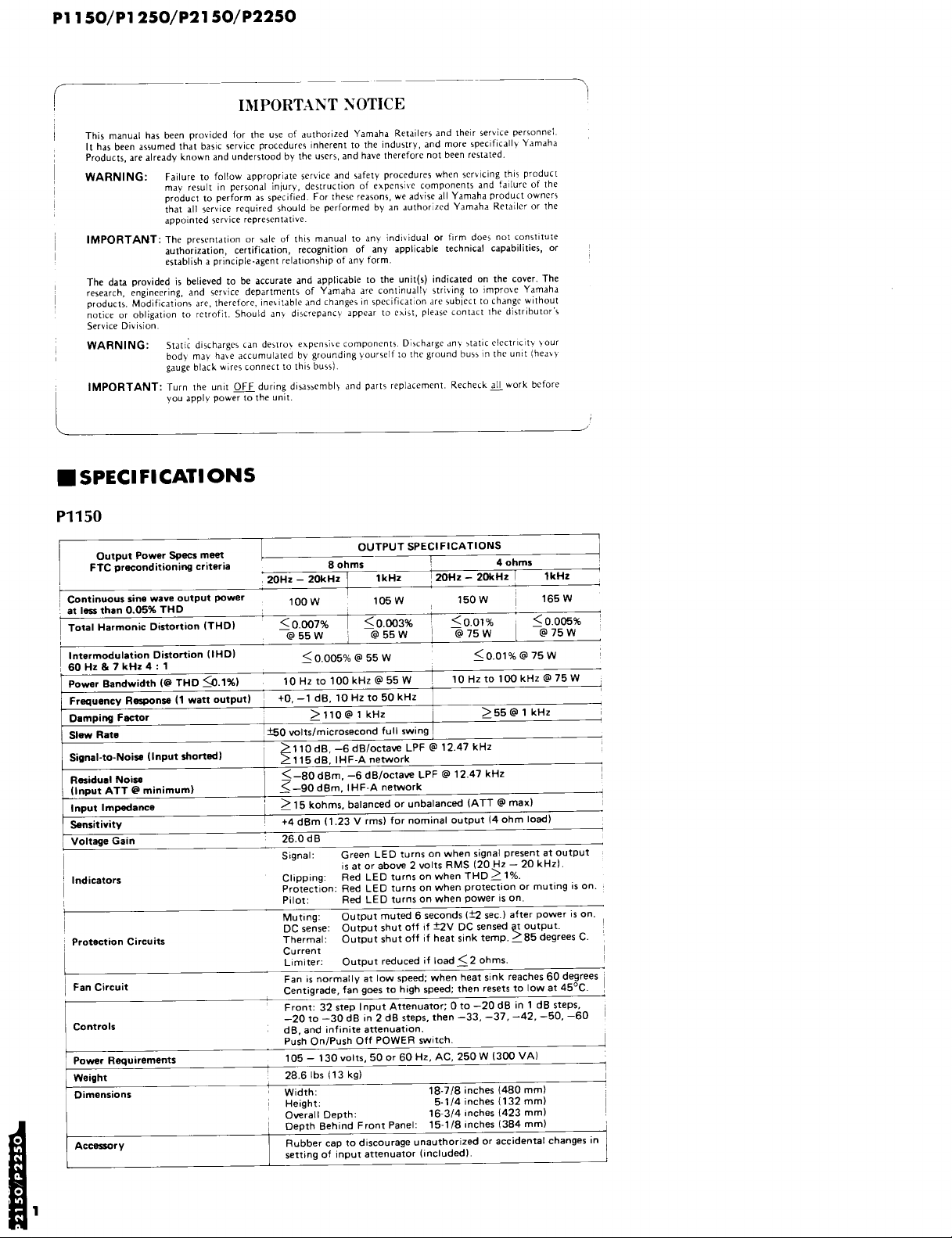
P1150
OutputP・werSp㏄珊eet.
FTCprecondltlonl㎎crlterla
20Hz−20kHz
Continuou55ino wa》e output powe「
Contlnuou551no wa》e output power
at Ie55than O.05%THD
TotaI Harmonic Di試ortion ITHD}
100W
<0.007%
@55W
IntermodulationDi試ortionllHD1
60Hz&7kHz4■1
60Hz&7kHz4.1
PowerBandwidthl@THO≦b.1%1 10Hzto100kHz@55W
F咽u。ncyR即。n鈎11watt・utputl
〈0.005%@55VV
+0、一1dB、10Hzt・50kHz
D8叩i㎎F魯。t。r ≧110@1kHz
SlewRato ±50volts/microsecondfuswing
>110dB,一6dBloctave LPF@12.47kHz
rignal−t。一N。i舗叩t甜。酬1 Σ115dBIHF−Ane㈱rk
Residual Noi駒
gnputATTOminimu耐 ≦一90dBm、IHF−Ane㈱rk
≦一80dBm,一6dBloctave LPF@12.47kHz
1叩utIm帥nce ≧15k・hms,baIan㏄d・runbalanc酬Aπ@max}
S。nsitivity +4dBm1123Vrms}f。rn・minal。utput14。hmlo副
VoItage Gain 260dB
VoItage Galn
Indicator5
Prot㏄tトon Circuits
FanCircuit
Contro15
Power Requirements
Weight
Olmenslon5
Oe on5
1
Acce錨ory
SlgnaI:
C踊PP監ng:
PrOtectionl
Pi IOt:
Muting:
DCsense:
Thermal:
Current
Umiter:
Fams normalIy at Iow speedl when heat sink reaches60degrees
Centigrade,fan goes to high speedl then resets to low at450C.
c
9 9 9
Front:32step InputAttenuator二〇to−20dB in l dB steps,
黷Q0to−30dB in2dB steps,then−33,一37,一42,一50,一60
рa,and inflnite attenuation.
oush On/Push Off POWER switch.
105−130volts、500r60Hz,AC,250W1300VAl
28.6bs(13kg}
Width 18−7!8inches(480mm}
Heigh之.
Overa目Depthl
Depth Behind Front PaneI:
Rubbercaptodiscourageunauthorizedoraccidentalchangesin
settmg of Input attenuator lincludedl.
OUTPUTSPECIFICATlONS
80hm5
80hm5
1kHz
105W
105W
<0.DO3%
20Hz−20kHz
<0.01%
@55W
Green LEDturnsonwhensignal presentatoutput
ls at or above2voIts RMS l20Hz−20kHzl・
Red LED tums on when THD≧1%.
Red LED turns on when protection or mutmg is on、
Red LED tums on when power is on.
Output muted6seconds l±2sec.}after power is on.
8廿器1廿舗認窯kS鷲竺§彗腸ee、c.
Output reduced if bad≦20hms、
5・114inches{132mm1
16−3/41nches{423mm)
15−1181nches l384mm}
一
t、、our
40hm5
150W
150W
@75W
<0.01%@75W
10Hz to100kHz@75W
>55◎1kHz
一
1kHz
165W
165W
<0.005%
@75W
P1150/P1250/P2150/P2250
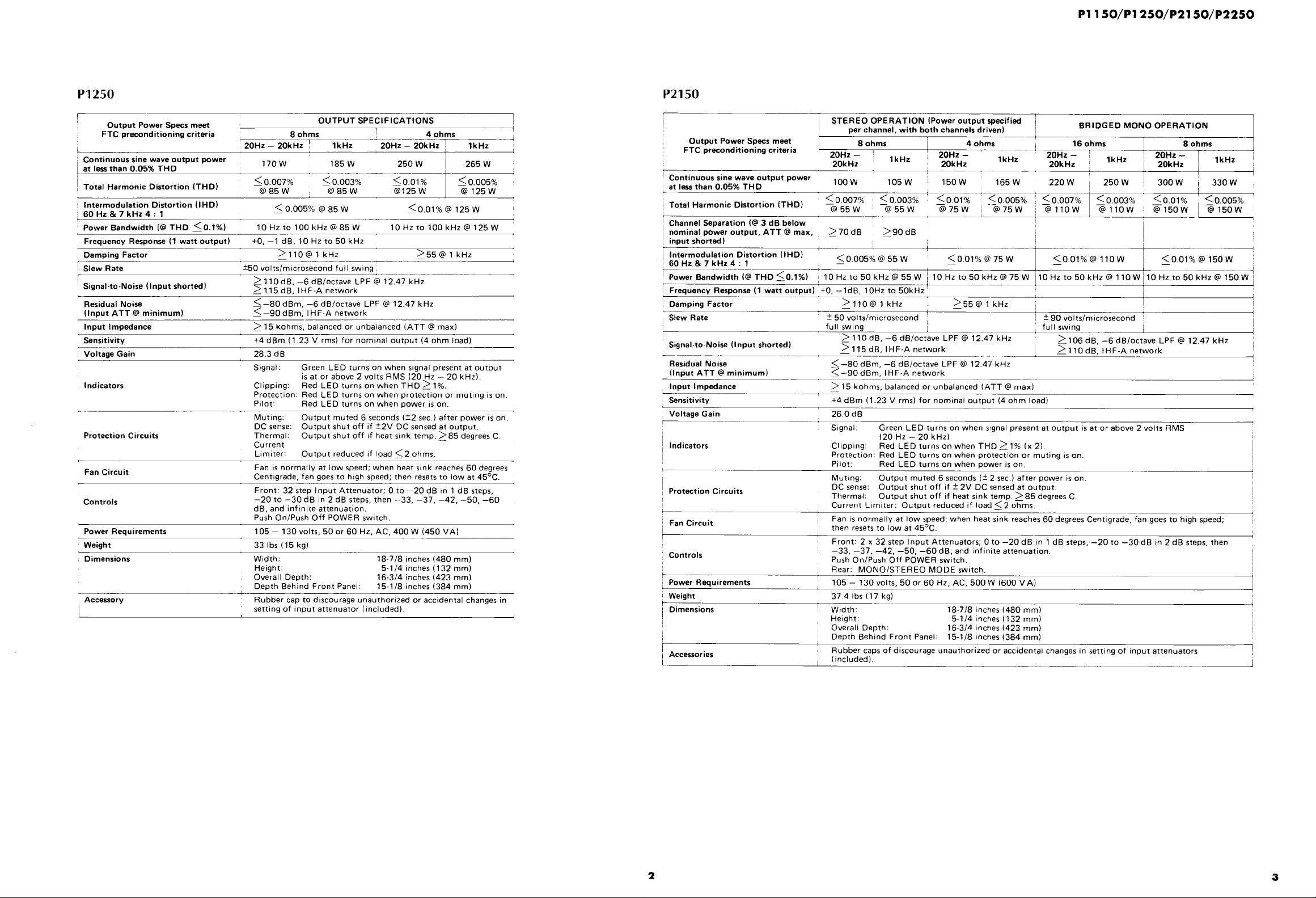
P1250
〇utput Power Specs meet
FTC preconditioning criteria
20Hz−20kHz
Continuous sine wave output power
at lessthan O.05%THD
TotaI Harmonic Distortion ITHm
Intermodulation Distortion(IHD}
60Hz&7kHz4:1
Power Bandwidth l@THD〈0.1%1
Frequency Response{1watt outpuΩ
Damping Factor
SIewRate
Signa卜to・Noise{lnputshorted}
ResiduaI Noise
ll叩utATT@minimuml
hput lmpedance
SensitivitY
VoltageGain
lndicators
Protection Circuits
Fan Circuit
Controls
Power Requirements
Weight
Dimensions
Acces船ry Rubbercaptodiscourageunauthorized oraccidentaI changesin
170W 185W
11U W
<0.007%一@85W
<0.005%@85W
10Hzto100kHz@85W
+0,一1dB,10Hzto50kHz
>110@1kHz >55@1kHz
±50)oIts/microsecond fuII swmg
>110dB,一6dB/octave LPF@12.47kHz
Σ115dB,I H F−A network
≦1−80dBm,一6dB/octave LPF@12.47kHz
≦一90d Bm,I H F−A network
>15kohms,baIancedorunbalanced(ATT@max)
+4dBm(1.23V rms}for nominal output l40hm bad)
28.3dB
Signaヒ
Chpping:
Protection:
Pilot
MutIngl
DC sense二
Therma1:
Current
Limiter:
Fan is norma料y at Iow speedl when heatslnk reaches60degrees
Centigrade,fan goes to high speed;then resets to bw at450C.
Front:32step InputAttenuator;Oto−20dB ln l dBsteps,
一20to−30dBin2dBsteps,then−33,一37,一42,一50、一60
dB,andinfiniteattenuation.
Push On/Push Off POWER switch.
105−130voIts,500r60Hz,AC,400W1450VA)
331bs(15kg)
Wldth二
Height:
OveraII Depth:
Depth Behind Front PaneI:
settlng of input attenuator(includedl.
OUTPUTSPECIFICATlONS
80hms 40hms
1kHz
1bb W
<0.003%
20Hz−20kHz lkHz
250W
ZbUW
<0.01%一@125W
265W
Zbb W
≦0、005%@↑25W
@85W
<0.01%@125W
10Hzto100kHz@125W
Green LED tumson when signaI presentatoutput
isat orabove2volts RMS(20Hz−20kHz}.
Red LED turnson when THD>1%.
Red LED turnson when protection or mutlng is on.
Red LED tumson when power is on.
Output muted6seconds(±2sec.}after power is on.
Outputshutoff if±2V DCsensed atoutput.
Outputshutoff if heatsink temp.>85degreesC.
Output reduced if Ioad≦20hms.
18−7/8inches l480mm)
5−1/4inches(132mm)
16−3/4inches(423mm)
15−1/8inches(384mm)
P2150
STEREOOPERATION IPoweroutput叩㏄ified
per channel,with both channels drivenl
Output PowerSp㏄smeet
FTC preconditioning criteria
l Continuous sine wave output power
at IessthanO.05%THD
Total Harmonic D恒tortion ITHDl
Channel Separation l@3dB below
nominal power output,ATT@max. >70dB
i叩utshortedl
IntermodulationDistort匪onHD)
60Hz&7kHz4:1
Power Bandwidth{@THD<01%}
Frequency Response(1watt outputl+0,一1dB,
Damping Factor
Sbw Rate
Signal−to・Noise Onput shorted}
Residual Noise
tortionHD)
THD<0.1%} 一
1
nputATT◎minimuml
1叩ut lmpωance
Sensitivity
VoltageGain
lndicators
Protection Circuits
Fan Circuit
一
Controls
Power Requirement5
Weight
ヒ
Dimensions
一
Accessories
20Hz 20Hz
20Hz−
20kHz
100W 105W 150W 165W
<0.007% <0.003% <0,01% <0,005%
@55W @55W @75W @75W
10Hzt。50kHz@55W110Hzt・50kHz@75W
︑
n
1dR lnH 『∩レH
>110@1kHz >55@1kHz
±50volts/microsecond
fuI I swing
>110dB・一6d8/0ctave LPF@12.4フkHz
>115dB,IHF−Anetw。rk
<一80dBm,一6dB/octaveLPF@12.47kHz
ζ一90dBm,旧FAnetwork
>15kohms,balanced or unbalanced(ATT@maxl
+4dBm(1.23V rmsl for nomina output{40hm Ioad〕
26.O dB
SIgnall
CIIPP旧g:
Protection:
Pilot:
Muting: Output muted6seconds(±2sec.)afterpower ison,
DC sense: Outputshutoff lf±2V DC sensed at outpl」t.
Thermal: Outputshutoff If heatslnktemp,≧85degrees C,
Current LImiter:Output reduced if Ioad<20hms.
Fan Is normally at bwspeedlwhen heatsink reaches60degreesCentigrade,fan goesto high speedl
then resets to Iow at450C.
Front:2x32step lnput Attenuators;Oto−20dB in l dB
−33,一37,一42,一50,一60dB,and lnfinite attenuation.
Push On/Push Off POWER switch.
Rearl MONOISTEREO MODE switch,
105−130volts,500r60Hz,AC,500W l600VA}
37,41bs(17kgl
Wldth: 18・7/8inches{480mm)
Height: 5−114inches32mm)
Overali Depthl 16−3/4inches(423mm}
Depth Behind Front Panel:15−1/8inches l384mml
RubbercapsofdiscourageunauthorizedoraccidentalchangesinsettingofInputattenuators
Gncluded).
P
80hms
1kHz
>90dB
40hms 160hm5
20Hz−
20kHz
r
1kHz
〈0.007%
BRIDGED一・PERAr「
20Hz
20Hz−
20kHz
220W
@O W
<0.01%@110W一
250W
<0.003%
■
@110W
10Hzto50kHz@110W 10Hzto50kHz@150W
10Hz to50kHz
±90volts/microsecond
fuIl swing
≧106dB,一6dB/octave LPF@12、47kHz
≧110dB,l H F−A network
Green LED turns on when s!gnaI present atoutput isat orabove2volts RMS
{20Hz−20kHzl
Red LED tumsonwhen THD>1%{x2}.
Red LED turns on when protection or muting
Red LED tums on when power is on.
『 on.
teps,一20to−30dBln2dBsteps、then
1kHz
80hm5
20Hz
20Hz−
20kHz
1kHz
300W 330W
<0.01% <0005%
石15・W L亜
<0.01%@150W−
2
3

P1150/P1250/P2150/P2250
■PERFOR…NCE G険APH5
P2250
STEREOOPERATIONIPoweroutput甲㏄ified
Output Power Sp㏄s meet
eTCpr㏄onditioningcriteria
Continuou55inewaveoutpotpower
≠煤@Iess than O.05%THD
Total Harmonic Distortion ITHDl
ChanneI Separation l@3dB below
獅盾高奄獅≠戟@poweroutput,ATT@max。
薗@utshortodl
lntermodulation Distortion(IHD1
U0Hz&7kHz4:1
Power Bandwidth l@THD≦0.1%1
Frequency Respon鈴{1wa賃outpuO
Damping Factor
Slew Rate
Signa1・to・Noise ≧110dB,一6dB/octave LPF@12・47kHz
撃撃獅垂浮狽唐暑edl ⊇≧115dB、1HFAne智vork
Residual Noise
撃撃獅垂浮狽TT@minimuml
lnput Impedance
Sensitivity
Voltage Gain 28.3dB
㎞dicators
Muting: Output muted6seconds(±2sec.l after power is on.
@
@
Fan Circuit
Controls
Power Requirements
Weight 1 4181bs(19kgl
Width: 18−718inches(480mml
@ Height: 5−114inches(132mm)Dimensions
@
Rubbercapstodiscourageunauthorizedoraccidental changesinsettingofinputattenuato「sAcc㈱ri馬 {includedl、
@ perchannel,withbothchannelsdriven}
20Hz−
Q0kHz
250W
<0,01%一@125W
>55@1kHz一
40hm5
1kHz
265W
<0.005%一@125W
20Hz−
Q0kHz
340W
〈0.007%『@85W
10Hz to50kHz@170W
±90volts!mlcrosecond
uII swing
80hms
20Hz−
Q0kHz
170W
<0.007%一@85W
>70dB一
1kHz
185W
<0.003%一@85W
﹀90dB一
10Hz to50kHz@85W
、+0,一1dB、10Hz to50kHz
>110@1kHz一
±50volts/microsecondi fuswing
10Hz to50kHz@125W
⊇≧106dB,一6dBloctave LPF@12.47kHz
≦一80dBm,一6dB/octave LPF@12.47kHz
+4dBm(1.23V rmsl for nominal output l40hm Ioad}
Signal: Green LED turns on when signal present at output is at or above2volts RMS
@ l20Hz−20kHz).
αipPing=RedLEDturns・nwhenTHD≧1%lx2)・
@ Protection:Red LED tums on when protection or muting is on.
PiIot: Red LED tums on when power is on.
DC sense: Outputshutoff if±2V DC sensed atoutput・P「otection Ci「cuits ThermaIl Output shut off if heat sink temp・≧85degrees C・
CurrentLimiter=Outputreducedifl。ad≦2・hms.
1惚nile繋1綴溝d;whenheatsink「eaches60deg「eesCentig「adefangoest。highspeed;
Fr。nt:2x32steplnputAttenuat・rslOt・一20dBinldBsteps,一20t・一30dBln2dBsteps・then
−33,一37,一42,一50,一60dB,and infinite attenuation.
Push On/Push Off POWER switch.
@ Rear: MONOISTEREO MODE switch.
105−130volts,500r60Hz,AC,850W1950VAl
0鴨ralIDepth: 16・314inches(423mm}
Depth Behind FrontPanel=15−118inches l384mml
BRIDGED MO柑00PERATION
160hm5
1kHz
370W
<0.003%一@85W
20Hz− 1kHz20kHz
500W 530W
<0.01% ≦0,005%一@125W @125W
10Hz to50kHz@250W
110dB,旧FA network
80hm5
THD vs OUTPUT POWER CHARACTERISTICS
<袖odel:P2150> Load lmpedance:4Ω
Mode:STEREO
Both Channels Driven
i妻妻i iiiiiiii li
訳一〇エ
0001
THD vs OUTPUT POWER CHARACTERISTICS
<IModel:P2150> Load lmpedance:8Ω
Mode:STEREO
BothChannels Driven
訳︸Oエ
.iコi
二一 一…・一一ヲー
.ノ『1
・イ集:= 1二
二コ ・i証≡芽イ二二ー・
__ ■ 撫 尋■_
2 5 10 2つ
OUTPUT POWER(Wl
・ご琶
業.璽{〜.
、翻r
『一一
@ 籏Hエ
OUTPUT POWER{W1
50 100 20) 5口0
THD vs OUTPUT POWER CHARACTERISTlCS
<]Mode1:P2150> Load Impedance:8Ω
Mode:MONO IBTLl
oo5
評
o
ヲ三三.一モ㍊皇璽三芝
二三三二f
ooo2
0001
一畑地
01 02 05
OUTPUT POWER l W l
50 100 20c 50c
THDvs FREQUENCYCHARACTERISTICS
qodel:P2150>
駅︸O
ooo2
10 20 50 脚 脚 蜘 1K 2民 5民 †OK 瓢 獣
FREOUEN℃Y 〔Hz〕
THD vs FREQUENCY CHARACTERISTICS
<㎞del:P2150> Load lmpedance:8Ω
Mode:STEREO
Both ChannelsDriven
Output Power:50W constant
ぷ一〇エ
ODO5
和 50 脚 獅 蜘 1【 2K
F『EOUENCY{Hz)
THD vs FREQUENCY CHARACTERISTICS
<袖odel:P2150>
ぷ一〇エ
OQO5
20 50 脚 脚 蜘 1K 2民
FREOUENCY IHz}
Load lmpedance:4Ω
Mode:STEREO
Both ChannelsDriven
Output Power:75W constant
Load lmpedance:8Ω
Mode:MONO(BTL}
Output Power:150VV constant
5暖 10K 2帆 獣
THD vs OUTPUT POWER CHARACTERISTICS
<南odel:一P2250> Load lmpedance:4Ω
Mode:STEREO
Both Channels Driven
o「
oo5
訳
一
〇〇2
0
一一一・・
ooo5
0002
01 02 05
4
5
OUTPUT POWERWl
樗
叢
THDvs FREQUENCYCHARACTERISTICS
く軸odel:P2250>
Load Impedance:4Ω
Mode:STEREO
Both Channels Driven
Output Power:125W constant
ま︸O
ooo5
ooo2
20 50
燗
FREOUE㏄Y{Hz)
禰 蜘
1K
2K
5K IOK 猷 50賦

P1150/P1250/P2150/P2250
THD甘s OUTPUT POWER CHARACTERISTlCS
〈Model:P2250> Load lmpedance:8Ω
Mode:STEREO
BothChanneIsDriven
02
01
005
訳
。
工
o o1
α005
0.002
01 02 05 1 2 5 ぬ き0 50 10c 獅
OUTPUT POWEn(Wl
−D vs OUTPUT POWER CHARACTERISTICS
<短bdel:P2250> Load Impedance:8Ω
0.oo1
二丁:1…一_襲一三一
Mode:MONO(BTL}
辛 一
斗 一 千 } 一
}
千 ← 一 }
一 一
弔 峠 チ 一 辛 }
一 一
一 一
一 一 六
w 一 一 一
A
@ 串
、
01
005
訳
o
工
oo1
αODs
一 一
→ 一 一 一
一 チ 一 壬 チ →
}
→ 一
一 一 一 子 一
誹 一
黶@ 一 }
一 一 一
ooo2
01 02 05 1 2 5 博
OUTPUT POWER{Wl
DAMPING FACTOR CHARACTERISTICS
〈Model:P2250> Load Impedance:8Ω
蜘
} 一 一
T 一 一
『 一 一 弔
一 }
4 升
{ →
チ 一 一 →
チ チ 千 一
l 一 }
,一一
害 一 }
き0 50 噸
⊥ 干 一 ←←
鋤
千 ユ 一
一 }
@』 『
号 一 一
一 一
→
一 一
l { 『 一
一 }
一 尋 一
@ ⊥ 一 一
@』 一 一 干
一 』 一 峠 }
チ 子 } 一
一 升 『 千
@→ ← 千 4 一 『
ィ チ チ 千 千 }
サ 千 斗 一
⇔一
100
0
0
0 20
…
ロ」 10
Σ
o
千 峠 千 一 }
』 一 一
ィ
} 一 千 } 『
l 手 ← 一 一 一
@ 一 一
1Lトセ
←
一
一 千
一
千
チ チ
千
チ
尋 ,
,r_
→
s
升
ひ2D←セ
獅
←←
一 ↓
黶@ 一
@一 _
黶@ 一
一 一
THD vs FREQUENCY CHARACTERISTICS
<IModel=P2250> Load Impedance:8Ω
Mode:STEREO
Both ChannelsDriven
Output Power:85W constant
一 一
一 → 壬 一 }
ol
{ 『 }
oo5
駅
》 o o2
0
工
勤
ODO2
0加1
10 20 50 畑 即 蜘 1K 2K 5K IOK 琳 獣
FREOUENCY{Hz,
THD vs FREQUENCY CHARACTERISTICS
<袖odel:P2250> Load Impedance:8Ω
MODE:MONO IBTLl
Output Power二250W
〒 千 一 } → → 辛 一 一 一 一
oo5
選
一
〇〇2
0
工
升 一 一 }
→ 千
} _ + 一
『 一 }
拳 一
r 陣 一
│ 一 県 }
, 一 }
{ 辛 壬 }
県 『 県 『
『 一 『 一
一
一 一 辛 一
}
皆 『 一 『
一 一 チ 串一
一
10 }0 50 獅 獅 蜘 、K 2K 5帳 10K 剛
FnEOUE㏄YてHzレ
FREQUENCY RESPONSE CHARACTERISTICS
q・del:am・de15> Loadlmpedance:8Ω
ooo1
Input Attenuators:Max
}} ⊥ 一
望一‡
睾二;
F音ECUE網CYH17
申 一 申 串 畔 一 } 一 一}
半一 事 } −
@ 十 一
− 艸
一 一
一 一 {
r 一
← 一 千 一 一
← ←
一 一 ¶ 一 一
一 斗 }一 }
一
一〒 一一
干 千 手 一 }
チ ∋
千 十 手 尋
}
一→ ← 一 尋 一
一 『 一
←尋 一
一
→ 県
{
一
一
一 寺
一 畢
千 十
→
申
断 皆一
FREOUE㏄Y{Hz,
6
P1150/P1250/P2150/P2250
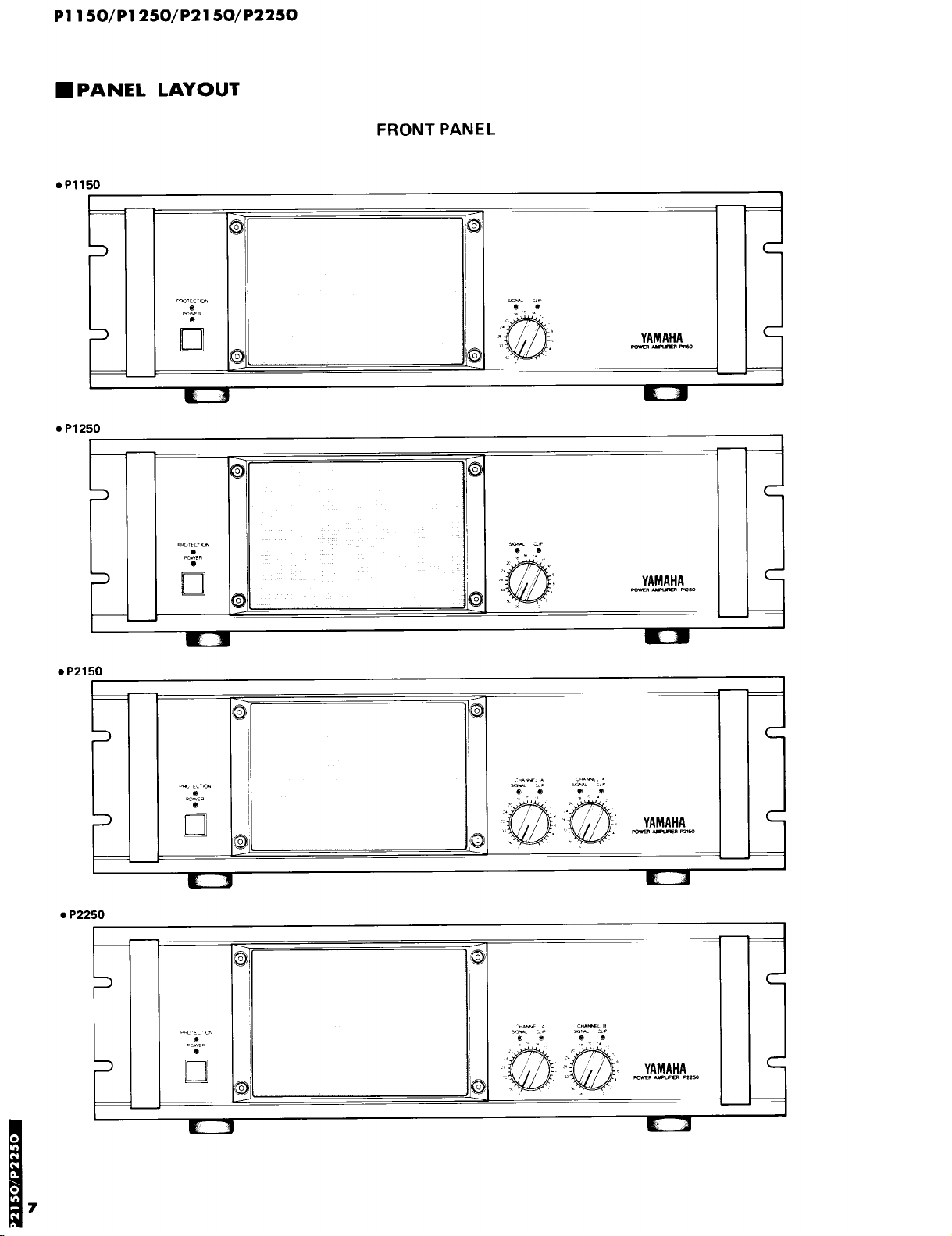
■PANEL LAYOUT
●P1150
◎◎
FRONT PANEL
◎i
m 撒﹃
●P1250
●P2150
饗罫
翠口
賢麗
◎
◎1
◎◎
ヲ 撒x
緊ざ
◎
◎ ◎
◎1◎
7
●P2250
㎜・
h□
饗
燃撒
◎ ◎
o□
1◎
P
・触
@響窒
㊨
m燃一

REAR PANEl{U.S.model}
P1150/P1250/P2150/P2250
●P50
●P1250
塵︑◎◎鎗
攣嵩1訓 ⑧
﹇ 剛璽鰻奪 壷鐙﹂ 嚇⑧
陣1 蘂◎6疑
●P2150
●P2250
同趣需許b
隅一
i
除
l梅壷,r 一息・ 一
③⑧
毒 群
議薦◎
8
 Loading...