


YAMAHA
AUTHORIZED
PRODUCT MANUAL P-2200/2201
SYSTEM AMPLIFIER

P-2200/2201
OPERATING MANUAL
ABOUT THIS MANUAL
SCOPE
The P-2200 is a system oriented amplifier, made to be used in conjunction with mixers, consoles, frequency dividing networks and speakers — those made by Yamaha or by other manufacturers. Like any power amplifier, the P-2200's performance depends on system design and installation, in addition to its own capabilities. Thus, the P-2200 Operating Manual is system oriented, describing system design parameters and installation techniques, as well as the operation and performance of the P-2200.
Additionally, this manual reviews a few of the basic mathematic tools used in system design, from dB to Ohm's law.
ORGANIZATION
We recommend that you read the entire Operating Manual. However, if you are using the P-2200 in an existing system, and you are familiar with high power
amplifiers, the BRIEF OPERATING INSTRUCTIONS, Pages One 1 & 2, contain all the information necessary for basic connections and operation.
The SPECIFICATION sections, (Sections THREE and FOUR) are highly detailed, including oscilloscope photos, and discussions of the P-2200's excellent performance specifications. The last part of the SPECIFICATIONS section is a discussion of the advantages of professional equipment, like the P-2200, compared to hi-fi or semi-pro equipment.
The INSTALLATION AND DETAILED OPERATION section, which begins on Page SIX 1, includes more complete instructions, special considerations for using the P-2200 "on the road," as well as in permanent commercial and studio installations. This section also covers grounding and shielding concepts, cabling considerations, and several other topics.
The APPLICATIONS section, which begins on Page SEVEN 1, discusses the use of the P-2200 in several typical setups, and includes wiring diagrams. This section also covers other devices that are normally associated with a power amplifier, from graphic equalizers to compressor/limiters.
The APPENDIX, on Page EIGHT 1, discusses definitions of a number of the terms used in the manual, and reviews some of the basic mathematic tools used in system design, such as the dB, Ohm's law, voltage division, and power formulas.
NOTE: The P2201 is identical to the P-2200 except there are no Peak Reading Meters.

THE P-2200/2201 BRIEF OPERATING INSTRUCTIONS |
SECTION ONE |
INTRODUCTION |
SECTION TWO |
GENERAL SPECIFICATIONS |
SECTION THREE |
PERFORMANCE GRAPHS & A DISCUSSION OF SPECIFICATIONS |
SECTION FOUR |
THE DISTINCTION BETWEEN PROFESSIONAL AND HI-FI EQUIPMENT |
SECTION FIVE |
IMPEDANCE |
1 |
OPERATING LEVELS |
2 |
DYNAMIC RANGE |
2 |
GAIN OVERLAP AND HEADROOM |
4 |
INPUT SENSITIVITY RATINGS |
4 |
PROFESSIONALEQUIPMENTADVANTAGES |
4 |
INSTALLATION AND DETAILED OPERATION |
SECTION SIX |
PHYSICAL MOUNTING |
1 |
CABLING AND IMPEDANCE MATCHING |
2 |
ACTIONS OF THE P-2200 PROTECTION CIRCUITS |
13 |
GROUNDING AND SHIELDING |
13 |
AC: POWER, FUSES, ACCESSORY OUTLETS, WIRING, SAFETY |
16 |
MONO OPERATION |
17 |
APPLICATIONS |
SECTION SEVEN |
BIAMPLIFICATION AND TRIAMPLIFICATION |
1 |
ECHO, REVERB AND DELAY |
3 |
COMPRESSION AND LIMITING |
3 |
EQUALIZATION, HIGH AND LOW PASS FILTERS |
4 |
SPEAKER PROTECTION |
6 |
SPECIFIC APPLICATIONS |
7 |
APPENDIX |
SECTION EIGHT |
DEFINITION OF TERMS: dB, dBV, dBm and dB SPL |
1 |
SPECIAL USE OF dB (VOLTS) IN THIS MANUAL |
1 |
OHM'S LAW |
2 |
POWER |
2 |
IMPEDANCE |
3 |
SERIES AND PARALLEL IMPEDANCE CONNECTIONS |
3 |
VOLTAGE AND CURRENT DIVISION |
4 |
BALANCED, UNBALANCED, AND FLOATING CIRCUITS |
5 |
TRANSFORMERS |
5 |
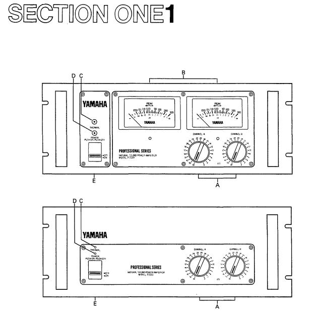
THE P-2200/2201 BRIEF OPERATING INSTRUCTIONS
Fig. 1A - P-2200 Front Panel
Fig. 1B - P2201 Front Panel
A.Input Attenuators
Calibrated, stepped input attenuators lower input
signal levels ahead of amplification stages.
B. Peak Reading Meters (P-2200 only)
Meters display instantaneous (peak) power output into an 8-ohm load over a full 50dB range; "0dB" = 100 Watts into 8 ohms.
C. Thermal Warning Indicator
Warns of overheating before thermal protection circuit turns off the AC power.
D.Power Indicator
Glows when the power switch is "on."
E.On-Off Switch
Controls AC power to the P-2200 or P2201.
NOTE: The P2201 is identical to the P-2200 except there are no Peak Reading Meters. Both are made to be mounted in a standard 19" wide electronic equipment rack. Each of them takes up 7" (17.6cm) of vertical space, and extends 13" (33.0cm ) behind its front panel. For portable racks, we recommend bracing the rear of
the amplifiers.
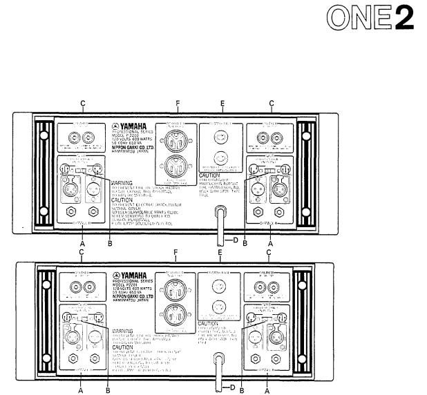
Fig. 2A - P-2200 Rear Panel*
Fig. 2B - P2201 Rear Panel*
A. Input Connectors
The two XLR input connectors on each channel are unbalanced and are wired in parallel with each other and with the two phone jacks (tip/sleeve type).
B. Input Polarity Switch
Determines the polarity of the two XLR input connectors (Pin 2 or Pin 3 "hot"); does not affect the two phone jacks. See diagram on the rear panel.
NOTES:
1.Input impedance is 25k-ohms minimum; +4dB (1.23V) produces 230 watts output into 8 ohms (44.7V).
2.Input channels may be parallelled by connecting
them together with phone to phone or XLR to XLR cables as shown on Page SIX 7.
3. Input transformers for matching or isolation, should be located several inches from the P-2200 or P2201's power transformer for maximum hum rejection.
C. Output Connectors
Standard 5-way binding posts (3/4" spacing) accept banana plugs or direct-wired connections.
NOTES:
1.Maximum power output into 8 ohms is 230 watts; power output rises at lower impedances.
2.Protection circuitry towers power output when
load impedance falls below 2.5 ohms.
D. AC Power Cord
For the U.S. and Canadian models, the P-2200/2201 require 117 VAC 50 or 60 Hz line (105 V min., 135 V max.; 8 amps max. at 120 volts).
For the Australian model: 240V AC 50 or 60 Hz.
For other territories' models, an internal voltage selector (220 V/240 V switchable) is provided near the rear panel. In this case 220 V is factory-preset. If you want to change into 240 V line, consult your nearest Yamaha dealer.
E. Fuses
7 amp, 125 volt (x 2), type AGC (3AG); U.S. and Canadian models only. 4 amp, 250 volt (x 2); other territories models. Fuses should always be replaced
with same size and type. If the fuses blow consistently, the amplifier should be checked by a qualified Yamaha
service technician.
F. AC Accessory Outlets
These convenience outlets are made for low power cooling fans. Not provided in certain areas.
 The rear panels shown here are subject to U.S. specifications.

INTRODUCTION
The P-2200 is not just "another big amplifier;" it is an exciting new approach to high power sound. Yamaha's leadership is clearly demonstrated by the P-2200's professional features, sophisticated design, and uncompromising performance.
PEAK READING METERS*
Instead of the more common and slow responding VU meters, the P-2200 has PEAK READING METERS that accurately display a full five decades (50dB) of output level. The peak meters have large, illuminated faces marked with dB and with watts into 8 ohms. The fast responding meters provide a better way to see the program dynamics, the transient power demands placed on the system, and the available headroom. By indicating headroom, the meters help the operator avoid overdriving the system, thereby preventing the "clipped" waveforms so dangerous to drivers and loudspeakers.
CALIBRATED INPUT ATTENUATORS
The P-2200 has log-linear INPUT ATTENUATORS to complement its peak reading meters. The input attenuators are marked in 22dB-calibrated steps, detented for extra accuracy. The attenuators provide a smooth, noise free transition from the highest to the lowest audio level. dB-calibrated input attenuators have numerous advantages: on the road, they allow predictable and repeatable setups; in commercial sound applications, they allow easy, accurate input sensitivity adjustments; in studios or discos, they let operators simultaneously adjust the level of two channels (or two programs on
separate amplifiers) with precise tracking.
INPUT AND OUTPUT CONNECTIONS
INPUT CONNECTORS for each channel include one "male" and one "female" XLR connector (unbalanced) plus two parallel phone jacks. This provides the flexi-
bility necessary for convenient bridging to another amplifier, as well as for adapter-free connection to almost any mixer. A POLARITY switch allows either
pin 2 or pin 3 of the XLR to be chosen as the "hot"
lead, satisfying DIN/JIS or USA standards. Outputs are standard five way binding posts, usable with high current "banana" plugs or direct wired connections.
MONAURAL OPERATION
The P-2200 may be converted to a monaural "super amplifier" by inserting two matched transformers
ahead of the inputs, feeding the same signal to both, and reversing the POLARITY switch on one input. This creates a transformerless balanced output, the speaker load "bridged" across the "hot" terminals of both
channels. In this mode, the P-2200 is suitable for
driving almost any load, including highly reactive 70-volt
commercial speaker lines. With a full 400 watts into
16 ohms, the P-2200 in mono mode eliminates the need for several smaller 70-volt amplifiers.
PERFORMANCE
The P-2200's performance is as impressive as its features. At a sustained output of 230 watts into 8 ohms (for each channel), there is plenty of punch to reproduce the powerful peaks essential to clean studio monitoring. High power handling also makes the P-2200 an unbeatable choice for live rock or disco sound systems, where an amplifier can really "cook" all night long. Power alone is no virtue; the P-2200 has ultra-low distortion, less than 0.05% THD at full rated power - the kind of low distortion that is undetectable by even the most critical listeners.
A high damping factor of better than 300 at frequencies below 1kHz reduces the tendency for speaker cone overshoot, giving tighter and better defined bass response. On the other end, the P-2200's frequency response extends well beyond 100kHz, enabling it to accurately reproduce the most complex musical waveforms — even the tortuous output of today's synthesizers. However, high frequency response has not been achieved at the expense of stability; in fact, the P-2200 is rock steady. Even when connected to highly reactive multi-speaker loads, there is no tendency to shut down or "take off" into spurious oscillation.
MECHANICAL CONSIDERATIONS
The P-2200 is constructed to withstand the high "G" forces encountered on the road. Its solid front panel mounts in any standard 19-inch rack, and, for a large amplifier, the P-2200 weighs a modest 44 pounds
(20kg)** Front panel controls and meters are recessed to avoid damage or accidental setting changes, and are
further protected by a pair of sturdy carrying handles. Inside and out, the P-2200 is extremely reliable. Still, should service ever be required, the unit is designed for easy access. Massive side-mounted heat sinks are designed for efficient cooling, making fans unnecessary
in all but the most severe thermal operating conditions. Four non-conductive feet ensure proper air flow when
the amplifier is shelf mounted, and avoid inadvertent ground loops. Multiple protection circuits make the amplifier nearly abuse proof and eliminate the need for troublesome DC power supply fuses.
*The P2201 does not have the Peak Reading Meters.
** The P2201 weighs 42 pounds (19kg)

GENERAL SPECIFICATIONS
Power Output Per Channel: (Refer to Figure 3. Ambient room temperature for tests: 25-degrees Centigrade.)
200 Watts continuous average sine wave power into
8 ohms with less than 0.05% THD, (Total Harmonic Distortion), over a bandwidth of 20Hz to 20kHz, both channels driven.
230 Watts continuous average sine wave power into 8 ohms with less than 0.05% THD, at 1 kHz, both channels driven.
Frequency Response: (Refer to Figure 5.)
+0dB, -0.5dB, 20Hz to 50kHz.
Total Harmonic Distortion: (Refer to Figure 6.)
Less than 0.005% @ 50 Watts, 8 ohms, 1kHz.
Less than 0.01% @ 150 Watts, 8 ohms, 20Hz to 20kHz.
Intermodulation Distortion: (Refer to Figure 7.)
Less than 0.01% using frequencies of 70Hz and 7kHz, mixed in a ratio of 4:1, single channel power output of 150 Watts into 8 ohms.
Input Sensitivity:
An input of +4dB* (1.23V), ±0.5dB, produces an output of 230 Watts into 8 ohms (maximum output power), INPUT attenuator set for maximum level.
Input Impedance:
25k-ohms, minimum (unbalanced).
Damping Factor: (@ 8 ohms / (Refer to Figure 8.)
Greater than 300 at any frequency from 20Hz to 1kHz; greater than 70 at any frequency from 20Hz to 20kHz.
Actual Output Impedance: (Refer to Figure 9.)
Less than 0.04 ohms, from 20Hz to 10kHz.
Hum and Noise:
At least 110dB signal-to-noise ratio (l.H.F./A.S.A. No. Z24.3-1944).
Rise Time:
3.8 microseconds, or better (10%-90% of 1 volt @ 1kHz square wave output).
Slew Rate:
45 volts per microsecond, or better (at 175 Watts into 8 ohms, 200kHz square-wave input).
Channel Separation: (Refer to Figure 10.)
At least 82dB at 1kHz, at least 75dB at 20kHz.
*In these specifications, when dB represents a specific voltage, 0dB is referenced to 0.775V. "dB" is a voltage level, whereas "dBm" is a power level. 0dBm is referenced to 1mW (0.775V driving a 600-ohm termination). For example, when 12.3V is fed to a high impedance, the level is designated "+24dB." When +24dB (12.3 volts) drives a 600-ohm termination, the level is designated "+24dBm." The level in "dB" is specified, wherever applicable, to avoid confusion when the input is fed by various low and high impedance sources. See the APPENDIX beginning on Page EIGHT 1 for a further discussion of dB.
Phase Shift: (Referto Figure 1 1 . )
20Hz to 20kHz, ±10 degrees.
OffsetVoltage:
Less than ±10mV DC.
Unit Step Function Response: (Refer to Figure 27.)
See scope photo (Page FOUR 4) and discussion, Page FOUR 6.
Thermal Specifications:
Massive black anodized heat sinks are thermally joined with the chassis, thereby utilizing the entire amplifier as a heat sink.
Protection Circuits:
Thermal warning light turns on when heat sink temperature reaches 100-degrees Centigrade.
A self-resetting thermal switch shuts down the AC power if the power transformer winding temperature reaches 130-degrees Centigrade. See Page SIX 13 for power overload circuit specs.
Turn On/Turn Off Specs:
There is no turn off transient; the turn on transient is minimal (see Page SIX 13). Warm up time is less than 0.2 seconds.
Power Requirements:
For the U.S. and Canadian models: AC, 120 Volts nominal, 50-60Hz (105V min., 135V max.); 8 amperes maximum at 120V AC; 960 volt-amperes maximum at 120 Volts; approximately 57 voltamperes at idle.
For other territories models: 1,300 Watts, 220 or 240 Volts AC nominal, 50-60Hz.
Efficiency: (Refer to Figure 12.)
As high as 63%; see Page FOUR 2.
NOTE: All performance specifications are made on U.S. and Canadian models at an AC line voltage of 120 Volts ±1%, using a ±1% nonreactive load resistor at an ambient room temperature of 25-degrees Centigrade. Also effective for other territories' models.
Input Connectors:
One "male" and one "female" XLR connector in parallel, pin 2 "hot," pin 3 connected to pin 1 (shield); switchable for pin 3 "hot." XLR's are unbalanced and in parallel with two tip-sleeve (standard) phone jacks.
Output Connectors:
Standard 3/4-inch spacing, "5-way" binding posts.
Meters and Indicators:
Two peak reading meters (one per channel) indicate the instantaneous power output, over a 5-decade (50dB) range. "0dB" represents 100 Watts into
8 ohms. (P-2200 only)
One "power ON" indicator LED; one "Thermal Overload" indicator LED.
Meter Rise Time (P-2200 only):
Less than 10 milliseconds; (-40dB to 0dB on the scale).
Meter Release Time (P-2200 only):
Less than 0.8 seconds; (0dB to -20dB on the meter scale).
Meter Accuracy (P-2200 only):
See graph, Figure 13, Page FOUR 2.

Controls:
22-position, log-linear, detented, and dB-calibrated INPUT ATTENUATORS (one per channel) attenuate input signal in 2dB steps from 0dB attenuation to -34dB, then steps of -37dB, -42dB, -50dB, infinity; Power (ON-OFF) switch; INPUT POLARITY switches.
Fuses:
AGC (3AG) type, 7-amps x 2 parallel fuses for the AC line input (U.S. and Canadian models). 4-amps x 2 parallel fuses for the AC line input (other territories' models).
Dimensions:
Mounts in a standard 19-inch (48cm) rack. 7" high (17.6cm); maximum depth behind front panel is 13" (33.0cm); maximum depth including front handles 14-1/2" (37.9cm).
Weight:
P-2200; 44 pounds (20kg), P2201; 42 pounds (19kg).
Color:
Semi-gloss black.
MONAURAL MODE SPECIFICATIONS
Power Output: (Refer to Figures 14 and 15.)
400 Watts continuous average sine wave power into 16 ohms with less than 0.05% THD, 20Hz to 20kHz.
Frequency Response: (Refer to Figure 16)
+0dB, -1dB, 20Hz to 50kHz.
Total Harmonic Distortion: (Refer to Figures 17 and 18.)
Less than 0.01% @ 300 Watts into 16 ohms at 1kHz.
Intermodulation Distortion:
Less than 0.05% using frequencies of 70Hz and 7kHz, mixed in a ratio of 4:1, at a power output of 200 Watts into 16 ohms.
Input Sensitivity:
An input of 0dB (0.775 Volts), ±0.5dB, produces an output of 200 Watts into 16 ohms (INPUT attenuator set for minimum attenuation, maximum level).
Input Impedance:
25K-ohms minimum (unbalanced).
Damping Factor: (@ 16 ohms) (Refer to Figures 19 and20).
Greater than 220 at any frequency from 20Hz to 1kHz; greater than 100 at any frequency from 20Hz to 20kHz.
Hum and Noise:
At least 110dB signal-to-noise ratio (I.H.F./A.S.A. No. Z24.3-1944).
Slew Rate:
35 volts per microsecond, or better, at 100 Watts into 16 ohms, 200kHz square wave input.
Specifications subject to change without notice.

PERFORMANCE GRAPHS &
A DISCUSSION OF SPECIFICATIONS
NOTE: In the discussion beginning on Page FOUR 5, references to specific specifications assume normal stereo operation (not mono operation) unless otherwise indicated.
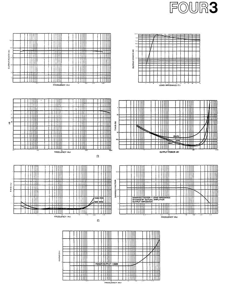
Normal (Stereo) Graphs
Fig. 3 - Power Bandwidth vs Load Impedance |
Fig. 4 - Load Impedance vs Output Power |
Fig. 5 - Frequency Response vs Load
Fig. 6A - T.H.D. vs Output Power at 8 Load Impedance |
Fig. 6B - T.H.D. vs Output Power at 16 Load Impedance |
(both channels driven) |
(both channels driven) |
Fig. 7 - Intermodulation Distortion vs Power Output at |
Fig. 8 - Damping Factor vs Frequency at 8 Load |
8 and 16 Load Impedance |
Impedance |
Fig. 9 - Actual Output Impedance vs Frequency |
Fig. 10 - Crosstalk (Channel Separation) |
Fig. 1 1 - Phase Response vs Frequency |
Fig. 12 - Power Consumption |
Fig. 13 - Peak Program Meter Accuracy (P-2200 only)
MonoModeGraphs
Fig. 14 - Power Bandwidth vs Frequency (Mono Mode) |
Fig. 15 - Load Impedance vs Output Power (Mono Mode) |
at 16 Load Impedance |
at 0.1% T.H.D., 1kHz |
Fig. 16 - Frequency Response (Mono Mode) at 16 Load
Impedance
Fig. 18 |
- T.H.D. vs Frequency (Mono Mode) at 16 Load |
Impedance |
|
Fig. 17 - T.H.D. vs Power Output (Mono Mode) at 16  Load Impedance
Fig. 19 - Damping Factor vs Frequency (Mono Mode) at 16  Load Impedance
Fig. 20 - Actual Output Impedance (Mono Mode) vs Frequency
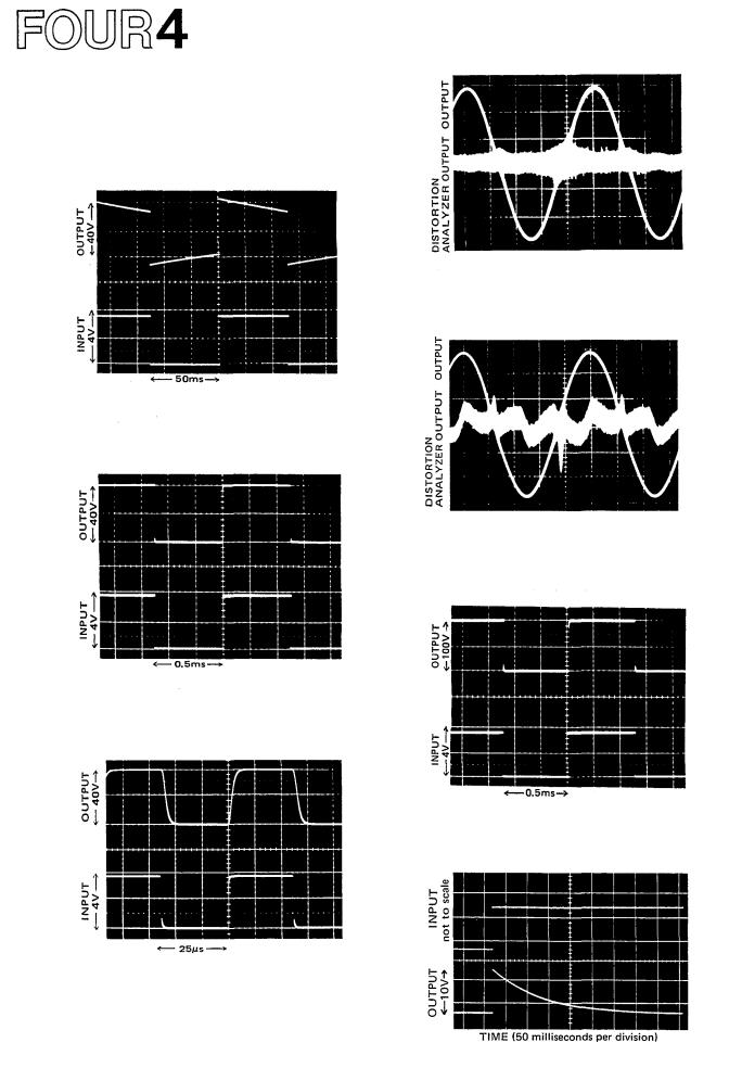
The following are actual oscilloscope photographs made by an independent testing laboratory. The close vertical alignment of input and output traces in Fig. 21 through 23 depicts very low phase shift, so the amplifier will not alter musical wave shapes.
Fig. 21 - 10Hz Square-Wave Response
The output waveform displays very respectable low frequency response. The slight "tilt" shows
a DC gain of unity, which prevents damage to speakers in the event any DC offset is fed to the amplifier input.
Fig. 22 - 1,000Hz Square-Wave Response
Near-perfect response is evident in the duplication of the input waveform by the output wave-
form. There are no "squiggles" or spikes, meaning there Is no ringing or overshoot.
Fig. 23 - 20,000Hz Square-Wave Response
The extremely fast and symmetrical rise and fall times of the amplifier are evident, demonstrating the ability to accurately reproduce musical waveforms and harmonics well beyond
the range of human hearing.
Fig. 24 - 1,000Hz Sine Wave, shown with HighlyMagnified Noise and Distortion Components
Even at full 230 watt output (8-ohms), the P-2200's distortion is so low that it is almost burried in the noise, which is at least 110dB
below the sine wave output. The sine wave is clean and symmetrical.
Fig. 25-20,000Hz Sine Wave, shown with HighlyMagnified Noise and Distortion Components
While no amplifier should ever have to produce 230 watts continuous output at 20kHz, the P-2200 does it with low distortion, and symmetrical reproduction. As In Fig. 11, the noise (magnified here) is actually better than 110dB below the sine wave.
Fig. 26 - Square-Wave Response into a Highly-
Inductive Load (at 1kHz)
The ability of the P-2200 to maintain a sharply defined square wave output into a reactive load demonstrates stability under the worst conditions. There is still a complete lack of unwanted ringing, as well as low phase shift.
Fig. 27 - Unit-step Function Response

POWER OUTPUT
Types of Power Ratings
Peak power refers to the maximum undistorted power output of an amplifier. Most amplifiers cannot sustain their peak power ratings for long periods of time without external cooling fans. Because there are many different methods of rating an amplifier's peak power, it is hard to objectively compare the peak power ratings of two amplifiers. The peak power rating is primarily useful
for determining an amplifier's ability to reproduce the peaks and transients in a musical program, peaks which may be 20dB or more above the average power level.
The ability to accurately reproduce these high power peaks in a musical program is one of the most important advantages of the P-2200 as compared to a smaller power amplifier.
"RMS"power is actually a misnomer for average power. Average power is usually measured with a sine wave input signal, and is equal to the amplifier's RMS output voltage squared and then divided by the load impedance (see Appendix). Because RMS voltage is used in the formula, the resulting power rating is commonly called "RMS power." While it means the same as "RMS power," to be more accurate, the P-2200 is rated in watts of "continuous average sine wave power."
Since the P-2200 is a professional power amplifier, not sold for home hi-fi use, it is not required to meet the power rating standard set by the FTC (Federal Trade Commission), a standard meant for consumer power amplifiers. However, the P-2200 is measured under severe conditions which simulate the most demanding professional usage. Thus, the P-2200 would easily meet the FTC ratings for consumer amplifiers. In addition, the P-2200 user has the benefits of professional features andreliability.
Reasons for a High Power Amplifier
An interesting characteristic of the human ear is described by the "Weber-Fechner" law. In its general form, the law applies to all our senses:
The amount of additional stimulus needed to produce a perceptible change is dependent on the amount of stimulus already present.
In mathematical terms, the Weber-Fechner law suggests that the human ear responds to changes in sound level in a logarithmic manner. More simply this means that for a sound to seem twice as loud, it requires approximately ten times as much acoustic power (and therefore ten times as much amplifier power). Thus, the P-2200's high power output capabilities are extremely valuable.
One of the other benefits of high power output is the ability of the amplifier to easily reproduce high peak power transients (which may be 100 times the average
program power, or even more). This subject is discussed further on Pages FIVE 2 and FIVE 4.
Power Output versus Load
Within its maximum limits, the P-2200 acts like a perfect voltage source (see Appendix), that is, its power output rises with decreasing load impedance. When the
load impedance drops below 2.5 ohms, the P-2200's
protection circuits begin to limit the power, resulting in the curve shown in Figure 4 (normal operation) and Figure 15 (mono operation).
DISTORTION (Refer to Figures 6A-B, 7, 17, 18) The P-2200 is designed to have the lowest possible
distortion. There are many different forms of distortion, however, and comprehensive distortion ratings offer a means to compare the performance of different amplifiers.
Harmonic Distortion, is characterized by the appearance at the amplifier output of harmonics of the input waveform which were not present in the original input waveform. Total Harmonic Distortion, or T.H.D. is the sum total of all of these unwanted harmonics expressed as a percentage of the total signal.
Harmonic distortion, in an amplifier, can be created in any of several ways. The T.H.D. rating of a power amplifier refers to creation of unwanted harmonics by the amplifier during "linear" operation (normal input and output levels, impedances, etc.). Harmonic distortion is also created by "clipping," a form of "non-linear" operation, which occurs when the signal level at an amplifier's input is high enough to drive the amplifier beyond its rated maximum output. The amplifier, in attempting to reproduce this signal, reaches its maximum output voltage swing before it reproduces the top of the signal waveforms. Since the output voltage cannot rise any farther, the tops of the waveform are "squared off," or clipped, as that shown in Figure 65. Clipping distortion adds odd upper harmonics (3rd harmonic,
5th, etc.) to the original signal. (Input clipping would be similar, where the input stage of the amplifier is overdriven by a high level input signal.) The P-2200 has wide input headroom and extremely high peak power output capabilities (headroom) to help avoid the problems of clipping distortion.
Another form of harmonic distortion that occurs in some power amplifiers is called crossover distortion. * Crossover distortion can be caused by improper bias in the output transistors of an amplifier. The amount of crossover distortion stays the same whether the signal is large or small, so the percentage of distortion goes down as the signal level goes up. Thus, an amplifier with crossover distortion may sound relatively distortion free at high output levels, yet sound "fuzzy" at low levels. Some amplifiers have internal adjustments which enable a service technician to control the amount of output transistor bias, and therefore control the distortion. The P-2200 has automatic biasing circuitry which needs no adjustment and avoids crossover distortion under all operating conditions.
Fig. 28A - Large Amplitude Sine Wave with Crossover
(notch) Distortion.
Fig. 28B - Smaller Amplitude Sine Wave with same amount (higher %) of Crossover (notch) Distortion.
"Crossover," in this case. refers to the transition between the positive half and the negative half of the output voltage wave- form in a "push-pull" class B or AB power amplifier: it has
nothing to do with the crossover used to divide frequencies in
a speaker system. See Figure 28.
Intermodulation Distortion, or I.M. is characterized by the appearance in the output waveform of frequencies that are equal to sums and differences of integral multiples of two or more of the frequencies present in the input signal. The difference between intermodulation distortion and harmonic distortion is that two or more different frequencies must be present to produce intermodulation distortion (only one frequency is needed for harmonic distortion to appear), and that intermodulation distortion products may not be harmonically related to the original frequencies. Like its harmonic distortion figure, the intermodulation distortion in the P-2200 is low enough to be virtually inaudible even in the most critical situations.
Dynamic Frequency Response Shift is related to both harmonic and intermodulation distortion. When high-level low and high frequency signals are present in the same waveform, the high frequency signals "ride" on top of the low frequency waveforms (see Figure 65, Page SEVEN 1). If amplifier headroomisinadequate, the low frequencies may "push" the high frequencies above the output limits of the amplifier, clipping them off the waveform (Figure 65C). The low frequencies may remain unaltered, but the
high frequencies are severely reduced. At the same time, harmonics of the high frequencies are produced which add to the super high frequency content of the signal. Thus, along with the distortion created by the clipping, the frequency response of the original signal is drastically altered. This type of distortion can be reduced by in-
creasing system headroom (using a more powerful
amplifier like the P-2200), and by biamplifying the system as discussed on Page SEVEN 1.
The extremely low distortion figures of the P-2200 indicate its overall quality and mean that its sound will be precise and natural.
FREQUENCY RESPONSE (Refer to Figures 5 & 16) The frequency response of the P-2200 describes the
variation in its output signal level with frequency when
the input signal is held constant. The extremely "flat" frequency response curve of the P-2200 is an indication of its overall quality and its ability to respond to upper and lower harmonics of signals all the way to the
extremes of the audio spectrum.
Because extreme stability is necessary for some types
of commercial sound applications, notably 70-volt lines
(see Page SEVEN 1 1 ) , some manufacturers restrict fre-
quency response or allow relatively high distortion in return for increased amplifier stability. The P-2200, on
the other hand, has excellent frequency response and ultra-low distortion, yet is inherently stable under the
most difficult loads, even in the "mono" mode.
The frequency response of the P-2200 has been
intentionally limited, however, at very low frequencies
(sub-audio). Because of this, severe low frequency transients, or DC offset, appearing at the input to the
P-2200 are unlikely to damage a speaker load. Other amplifiers which are DC coupled throughout may have a "flatter" sub-audio frequency response, but this makes
them capable of amplifying dangerous DC input voltage
or sub-audio transients and delivering them (at high power) to a speaker.
OFFSET VOLTAGE
This specification indicates the amount of DC voltage naturally present at the output of the amplifier. A high DC voltage could damage the loudspeaker load; the
±10mV (10 one-thousandths of a volt) level from the P-2200 is insignificant.
UNIT STEP FUNCTION RESPONSE (Refer to Figure 27) A unit step function is like the leading edge of a
square wave; it goes up, but never comes down. The response to this input indicates the output of the P-2200 for a DC input signal which might come from a faulty direct coupled preamplifier or mixer. Note that the P-2200 will not reproduce a DC voltage fed to its input, thus adding an extra measure of loudspeaker protection.
POWER BANDWIDTH (Refer to Figures 3 & 14)
The power bandwidth of the P-2200 is a measure of its ability to produce high power output over a wide frequency range. The limits of the power bandwidth are those points where the P-2200 can only produce 1/2 the power that it can produce at 1000Hz. While the frequency response is measured at relatively low power output (1 watt), the power bandwidth is measured at the P-2200's full power output (before clipping). The power bandwidth of the P-2200 is quite "flat," and extends to 200kHz, well beyond the limits of the audio spectrum.
The wide power bandwidth of the P-2200 means that it can reproduce high level upper harmonics of a signal as easily as it can reproduce mid-range fundamentals. It means that you get full power performance from the P-2200 over the entire audio frequency spectrum. This is especially important when the amplifier is called upon to reproduce musical material with high energy over a wide frequency range, such as rock and roll.
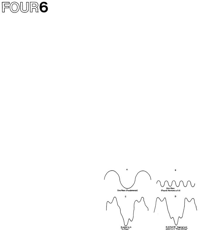
PHASE RESPONSE (Refer to Figure 11)
The phase response of the P-2200 is a measure of the amount of time delay it adds to different frequencies.
An amplifier with perfect phase response would introduce equal time delay at all frequencies reproduced. The P-2200's worst case phase shift of -10 degrees at 20kHz corresponds to a 1.4 microsecond (1.4 millionths of a second) delay period which is insignificant in even the
most critical audio applications.
Fig. 29 - Waveform of Amplifier with Poor Phase Response.
An amplifier with poor phase response would change the shape of a waveform that was made up of a fundamental frequency and several harmonics by delaying
each harmonic differently. The effect might be similar to that shown in Figure 29.
CHANNEL SEPARATION (Refer to Figure 10)
This specification indicates the output from one channel when a signal is fed to the other channel. The
P-2200's channel separation is very good, which means
that even critical stereo programs will be unaffected by crosstalk between channels.
HUM AND NOISE
Hum or noise from a power amplifier disrupts a program, and is irritating to a listener. Hum and noise could be considered a form of distortion. The P-2200's hum and noise are so low that they are completely inaudible under any normal listening circumstances.
RISE TIME
Rise time is a measurement of the amount of time an amplifier requires to respond to a square wave at a specified frequency. The rise time of an amplifier is an indication of its frequency response. A fast rise time corresponds to a wide frequency response. The P-2200's rise time specification is measured with a 1000Hz square wave output signal of one volt peak-to-peak amplitude. The rise time is the time the amplifier requires to change from 10% (0.1 volt) to 90% (0.9 volt) of its output. To improve measurement accuracy, the first and last 10% are normally not included in the test (any slight nonlinearities that occur in the test signal or the amplifier could lead to measurement error).
SLEW RATE
Slew rate is a measure of a power amplifier's ability to follow a fast rising waveform at higher frequencies and higher power outputs than the rise time measurement. The P-2200's slew rate is measured with a 200kHz square wave input signal, at 175 Watts output power into 8 ohms.
It might seem reasonable to assume that the fastest slew rate for an audio waveform occurs at 20kHz.
However, this is not the case. When one frequency is superimposed upon another, the combined waveform has a slew rate that is greater than the slew rate of either signal by itself. The actual value of the slew rate
of one of these waveforms (or any waveform) depends not only on the frequency, but on the amplitude of the waveform as well. Thus, the criteria for a good slew rate specification, which indicates that an amplifier can
reproduce these combination waveforms, varies with the maximum power output capability of the amplifier. The higher the power, the higher the required slew rate.
With a 45 volts/microsecond slew rate, the P-2200 can easily reproduce even the most extreme audio waveforms at its full power output.
INPUT IMPEDANCE
The input impedance of the P-2200 is high enough to allow it to be used with most semi-pro devices, or to be used as a "bridging" load for a 600-ohm source.
Page SIX 2 details input impedance and level matching for the P-2200.
INPUT SENSITIVITY
The P-2200's input sensitivity indicates the input drive voltage needed for the P-2200 to produce its
rated output of 230 watts into 8 ohms (input attenuators are adjusted to maximum clockwise rotation for minimum attenuation).
PROTECTION CIRCUITS AND
THERMAL SPECIFICATIONS
See the discussions under INSTALLATION, on Page SIX 13.
GAIN
Gain is the ratio of the P-2200's output voltage to its input voltage. Maximum gain occurs when the input attenuators are set for minimum attenuation. If the input
and output voltage are specified in dB, the voltage gain is equal to the difference of the two dB numbers. As stated under INPUT SENSITIVITY, an input voltage of +4dB
(1.23 volts) produces an output power of 230 watts into
an 8-ohm load. 230 watts into 8 ohms implies an output voltage of 43 volts which corresponds to +35dB (referenced to 0.775 volts, as used in this manual). The voltage gain of the P-2200, with its input attenuators set
for minimum attenuation, then, is 31dB [(+35dB)-(+4dB)].
OUTPUT IMPEDANCE (Refer to Figures 9 & 20) The output impedance of the P-2200 is extremely
low. Thus, within its operating limits, the P-2200 is a good approximation of a perfect voltage source and will deliver increasing power levels into lower impedance loads in a linear fashion according to Ohm's law. The Appendix discusses Ohm's law and the concept of a perfect voltage source.
DAMPING FACTOR
Damping factor is a term that is derived by
dividing the load impedance (speaker or other load) by the amplifier's output impedance. Thus, a high damping factor indicates a low output impedance at a specified load.
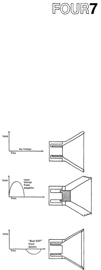
The cone/voice-coil assembly of a loudspeaker gains inertia during its back and forth movements. This inertia can cause it to "overshoot," that is, to continue movement in one direction, even when the amplifier is trying to pull it back in the other direction. An amplifier with a low output impedance can "damp" (reduce) unwanted loudspeaker motions, as explained below.
Fig. 30A - Speaker Cone at Rest
Fig. 30B - Speaker Cone moved outward by Postive-Going
Voltage from Amplifier.
Fig. 30C - Voltage from Amplifier has dropped to Zero but
Speaker Cone has moved back PAST its rest position (overshoot) and is producing a voltage of its own: "Back EMF"
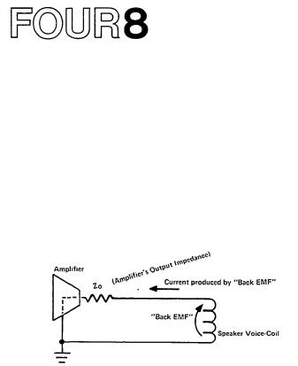
During the "overshoot" movement, the voice coil of the loudspeaker interacts with the loudspeaker's magnetic assembly to produce a voltage called "back E.M.F." (electro-motive force). This action is similar to the operation of a dynamic microphone. If the amplifier's output impedance is low, this "back E.M.F." voltage is shunted through the amplifier's output circuits to ground, and back to the voice coil. Since the path from the voice coil, through the amplifier's output circuits, and back to the voice coil is a complete circuit, a
current flows in the voice coil. This current, causes the voice coil to act like an electro-magnet; the electro-
magnet (voice coil) interacts with the magnetic assembly of the loudspeaker, and the unwanted overshoot is reduced (a magnetic braking action).
Fig. 31 - Current produced by "Back EMF" follows path through Amplifier's Output Impedance to speaker-coil.
If the amplifier's output impedance is low (considerably less than the impedance of the loudspeaker voice coil), this damping action is limited only by the
resistance of the voice coil combined with the resistance of the speaker lead wires. While the value of a high damping factor in reducing cone overshoot is disputed,
the P-2200's high damping factor is evidence of good overall engineering design.
THE DISTINCTION BETWEEN PROFESSIONAL AND HI-FI EQUIPMENT
In most applications, a variety of auxiliary equipment will be connected to the P-2200, including: mixers, tape machines, compressors, graphic equalizers, echo, time delay, and reverb units, and just about any other audio electronics imaginable. Regardless of the function of auxiliary equipment, it will undoubtedly fall into one of two general categories, professional type or hi-fi type. The following criteria place most "semi-pro" equipment in the hi-fi classification.
The distinction between professional and hi-fi equipment is important primarily because it affects the way it will be used with the P-2200. Brand name, size, panel colors, durability and subtleties in function are not the significant differences. What matters is that professional equipment and hi-fi equipment usually operate at different input and output levels, and require different source and load impedances to function properly. The P-2200 is designed to function well with other professional equipment, although it has high enough input impedance and sensitivity to yield excellent results with hi-fi type equipment if a few precautions are observed. (These precautions are outlined in the Installation section of the manual.) The following paragraphs explain how the specific requirements differ for professional and hi-fi (or semi-pro) equipment.
IMPEDANCE
The inputs of a piece of professional audio equipment are usually designed to be driven from a low impedance source, nominally 150 to 600 ohms, and its outputs will drive low impedance (600 ohm or higher) loads. (Power amplifier outputs are not considered in this discussion.) Professional input and output circuits may be unbalanced, but they are often transformer isolated (balanced or floating), and use dual conductor shielded cables, with 3-pin XLR type connectors or Tip/Ring/ Sleeve phone plugs.
The P-2200's inputs are unbalanced due to cost and adaptability factors. To internally balance the inputs of the P-2200 would require two matched input transformers with heavy shielding (to avoid hum pickup from
the P-2200's power transformer). Induced hum in low level circuits, especially in low level transformers, can be a problem with any power amplifier, or other high current device (such as a DC power supply). High quality external transformers with less shielding can achieve the same results with a substantial cost savings. In addition, the user can choose the optimum impedance ratio for
a given situation, increasing the P-2200's adaptability. Either the "matching transformer box" or "step up
transformer box" described on Pages SIX 3, and SIX 4 are suitable, so long as they are kept several inches away from the P-2200.
Hi-fi (and semi-pro) equipment generally is designed to be driven from a 5,000-ohm (or lower impedance) source, and its output will drive 10,000-ohm (or higher impedance) loads. Hi-fi input and output circuits are
usually unbalanced, and use single conductor shielded cables with 2-conductor connectors, either standard phone plugs or phono plugs (also called RCA or pin plugs). Occasionally, the inputs of a piece of hi-fi or semi-pro equipment are professional XLR connectors which have been converted to a 2-wire, unbalanced circuit by internally connecting either pin 2 or pin 3 to pin 1.
The nature of unbalanced, balanced, and floating circuitry is discussed further in the Appendix of this manual. For the purpose of this discussion, the most significant point is that an unbalanced circuit is somewhat more susceptible to hum and noise, especially if there is any irregularity in the grounding system. NOTE: THERE IS NO CORRELATION BETWEEN "BALANCED" OR "FLOATING" AND CIRCUIT IMPEDANCE.
Low impedance and high impedance are relative terms. A 150to 250-ohm microphone is considered low impedance, whereas a 10,000-ohm mic is considered high impedance. A 600-ohm line is considered low impedance, whereas 10,000-ohm, 50,000-ohm or 250,000-ohm lines are all considered high impedance. Sometimes, mics and lines with an impedance of 600 ohms to about 2000 ohms are considered "medium" impedance. NOTE: THE IMPEDANCE OF A CIRCUIT SAYS NOTHING ABOUT ITS LEVEL.
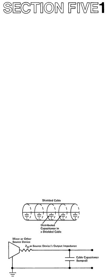
While the exact transition between low and high impedance is not clearly defined, the distinction is still important, primarily because the output impedance of a source determines the length of cable that can be connected between it and a load before a serious loss
of high frequencies occurs. The losses occur because all cables, and especially shielded cables, have some capacitance between their conductors. Some guitar coil cords may measure as high as 1000 picofarads total capacitance! A source impedance (such as a high impedance mixer output) and the capacitance of a cable form a type of low-pass filter a filter that attenuates high frequencies. This filtering effect, can be reduced by using low capacitance cable, by shortening
the length of the cable, by using a low impedance source or by some combination of these methods.
Fig. 32 - The Source's Output Impedance and the Cable
Capacitance act as an "RC Lowpass" Filter which Attenuates High Frequencies.
 Loading...