

Yamaha MT-400 Service Manual
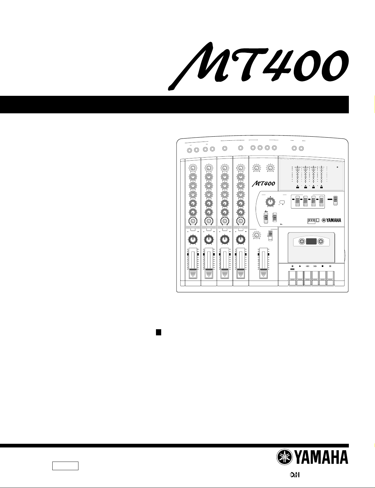
MULTITRACK CASSETTE RECORDER
SERVICE MANUAL
MIC/LINE INPUT
INSERT I/O
2
INSERT I/O
1
1
GAIN
GAIN
LINE MIC
LINE MIC
HIGH
HIGH
–12 +12
–12 +12
MID
MID
–12 +12
–12 +12
LOW
LOW
–12 +12
–12 +12
AUX
AUX
1
1
010
AUX
2
MIX CUE
MIC/LINE
to L
TAPE
PAN
10
9
8
7
6
5
4
3
2
1
0
010
AUX
2
010
010
MIX CUE MIX CUE MIX CUE
010
010
TAPE
MIC/LINE
to R
MIC/
TAPE
LINE
INPUT-FLIP
INPUT-FLIP
PAN
LR
LR
10
9
8
7
6
5
4
3
2
1
0
2
TAPE
MIC/
LINE
3
GAIN
LINE MIC
HIGH
–12 +12
MID
–12 +12
LOW
–12 +12
AUX
1
010
AUX
2
010
010
MIC/LINE
to L
TAPE
INPUT-FLIP
PAN
LR
10
9
8
7
6
5
4
3
2
1
0
3
TAPE
MIC/
LINE
4
GAIN
LINE MIC
HIGH
–12 +12
MID
–12 +12
LOW
–12 +12
AUX
1
010
AUX
2
010
010
MIC/LINE
to R
TAPE
INPUT-FLIP
PAN
LR
10
9
8
7
6
5
4
3
2
1
0
TAPE
MIC/
LINE
4
LEVEL
LEVEL
MIN MAX
STEREO INPUT
L 6R 8R7L
5
7
5L–6
R
LEVEL
010
010
MULTITRACK CASSETTE RECORDER
TAPE SPEED CONTROL
PITCH
–
SYNC
MONITOR/PHONES
STEREO
ST+CUE
CUE
STEREO
10
9
8
7
6
5
4
3
2
1
0
L–8R
ZERO STOP
ON
OFFONOFF
+6
+3
0
–5
–10
REC
1
OFF
4.8/ 9.5
+
NOISE REDUCTION SYSTEM
REC PLAY REW FF STOP PAUSE
AUX SEND
1
L
2
+6
POWER
+3
0
–5
–10
4
321
RL
3
2
OFF
OFF
L
R
METER SELECTREC SELECT
4TR4
STEREO
OFF
R
011437
PA
19981101-45000
CONTENTS
SPECIFICATIONS ................................................ 3/4
DIMENSIONS ........................................................... 4
PANEL LAYOUT .................................... 5
CIRCUIT BOARD LAYOUT ................. 8
BLOCK DIAGRAM
............................ 9
DISASSEMBLY PROCEDURE ............................ 10
IC BLOCK DIAGRAM .................................. 11
CIRCUIT BOARDS ...................................... 12
INSPECTIONS ....................................................... 15/17
TROUBLE SHOOTING ............... 19
CIRCUIT DIAGRAM ............................................... 21
PARTS LIST
HAMAMATSU, JAPAN
1.95K-998 Printed in Japan ’98.10
MT400
IMPORTANT NOTICE
This manual has been provided for the use of authorized Yamaha Retailers and their service personnel. It has been assumed
that basic service procedures inherent to the industry, and more specifically Yamaha Products, are already known and understood by the users, and have therefore not been restated.
WARNING : Failure to follow appropriate service and safety procedures when servicing this product may result in per-
IMPORTANT : This presentation or sale of this manual to any individual or firm does not constitute authorization certifi-
The data provided is belived to be accurate and applicable to the unit(s) indicated on the cover. The research engineering, and
service departments of Yamaha are continually striving to improve Yamaha products. Modifications are, therefore, inevitable
and changes in specification are subject to change without notice or obligation to retrofit. Should any discrepancy appear to
exist, please contact the distributor’s Service Division.
WARNING : Static discharges can destroy expensive components. Discharge any static electricity you body may have
IMPORTANT : Turn the unit OFF during disassembly and parts replacement. Recheck all work before you apply power
sonal injury, destruction of expensive components and failure of the product to perform as specified. For
these reasons, we advise all Yamaha product owners that all service required should be performed by an
authorized Yamaha Retailer or the appointed service representative.
cation, recognition of any applicable technical capabilities, or establish a principal-agent relationship of
any form.
accumulated by grounding yourself to the ground buss in the unit (heavy gauge black wires connect to
this buss.)
to the unit.
WARNING: CHEMICAL CONTENT NOTICE!
The solder used in the production of this product contains LEAD. In addition, other electrical/electronic and/or plastic (Where
applicable) components may also contain traces of chemicals found by the California Health and Welfare Agency (and possibly
other entities) to cause cancer and/or birth defects or other reproductive harm.
DO NOT PLACE SOLDER, ELECTRICAL/ELECTRONIC OR PLASTIC COMPONENTS IN YOUR MOUTH FOR ANY REASON WHAT
SO EVER!
Avoid prolonged, unprotected contact between solder and your skin! When soldering, do not inhale solder fumes or expose
eyes to solder/flux vapor!
If you come in contact with solder or components located inside the enclosure of this product, wash your hands before handling
food.
WARNING
Components having special characteristics are marked and must be replaced with parts having specification equal to those
originally installed.
2
SPECIFICATIONS
Tape Transport
MT400
Tape Type
Track Configuration
Tape Heads
Motor
Tape Speed
Pitch Control
Wow & Flutter
Rewind Time
Mixer
Frequency Response
S/N Ratio (at rated input &
output levels)
EQ
Recorder
Overall Frequency Response
Overall S/N Ratio
Overall Distortion
Erasure Rate
Noise Reduction
C46–90 cassette tapes (Type II)
4-track/4-channel, One-way Record-Play
4-track Record-Play, Hard Permalloy x 1, 4-track Erase, Ferrite x1
DC servo motor x1
4.8 cm/s, 9.5 cm/s
Approximately+/–10%
0.12% WRMS (9.5 cm/s)
Approximately 120 seconds for a C60 tape
20 Hz–20 kHz, +1/–4 dB, MIC IN—STEREO OUT
LINE IN—MONITOR OUT
65 dB/IHF-A, MIC IN—STEREO OUT (GAIN TRIM MAX)
70 dB/IHF-A, LINE IN—STEREO OUT (GAIN TRIM MIN)
LOW/Shelving Basic frequency: 80 Hz, Range: ±12 dB
MID/Peaking Basic frequency: 1 kHz, Range: ±12 dB
HIGH/Shelving Basic frequency: 12 kHz, Range: ±12 dB
50 Hz–14 kHz, +3/–5 dB (9.5 cm/s, NR OUT)
80 dB/IHF-A (NR IN) [at 3% distortion level]
2.0% (400 Hz, –10 dB)
55 dB (1 kHz, 0 dB, BPF)
dbx TYPE II
STEREO OUT L, R
AUX SEND
MONITOR OUT
SYNC OUT
PHONES (STEREO)
Output Impedance: 1 k ohm
Rated Load Impedance: 10 k ohm or higher
Rated Output Level: –10 dB (10 k ohm load)
Output Impedance: 1 k ohm
Rated Load Impedance: 10 k ohm or higher
Rated Output Level: –10 dB (10 k ohm load)
Output Impedance: 1 k ohm
Rated Load Impedance: 10 k ohm or higher
Rated Output Level: –10 dB (10 k ohm load)
Output Impedance: 1 k ohm
Rated Load Impedance: 10 k ohm or higher
Rated Output Level: –10 dB (10 k ohm load)
Rated Load Impedance: 8 to 40ohm
Rated Output Level: 30 mW+30 mW (40ohm load)
Control Jack
PUNCH I/O Foot switch: FC5 (optional)
General
Power Requirement
Dimensions (WxHxD)
Weight
Option for UK model
0 dB=0.775 Vrms.
DC 12V (650 mA or higher)
388 x 102 x 354 mm
2.8 kg
AC adapter KPA4N, KPA6N
Connections
# of I/Os
I/O Specifications
MIC/LINE
INSERT IN CH 1, 2
STEREO IN
INSERT OUT CH 1, 2
MIC/LINE x4
INSERT I/O x2
STEREO IN x2
AUX SEND x2
STEREO OUT L, R x1
MONITOR OUT L, R x1
SYNC OUT x1
PHONES L, R x1
Input Impedance: 10 k ohm
Rated Input Level: –10 to –50 dB (CH fader at rated levels)
Minimum Input Level: –56 dB (Gain trim max. CH fader max)
Input Impedance: 10 k ohm
Rated Input Level: –10 dB (CH fader at rated levels)
Minimum Input Level: –16 dB (CH fader max)
Input Impedance: 10 k ohm
Rated Input Level: –10 dB (CH fader at rated levels)
Minimum Input Level: –16 dB (Volume max)
Output Impedance: 100ohm
Rated Load Impedance: 10 kΩ or higher
Rated Output Level: –10 dB (10 kΩ load)
3
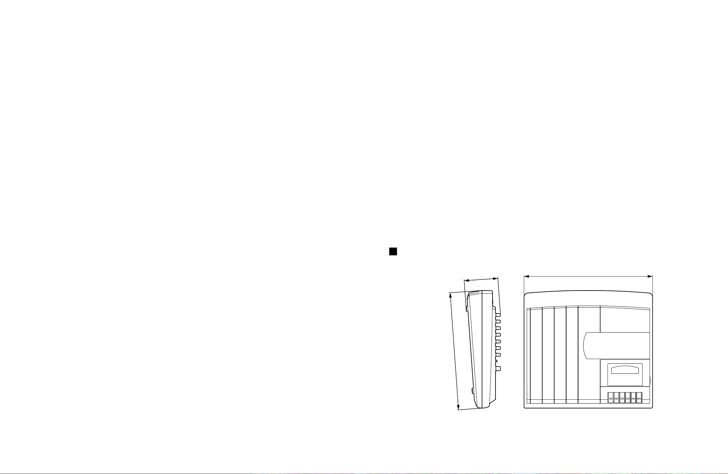
MT400
H:102
D:354
W:388
DIMENSIONS
Unit : mm
4
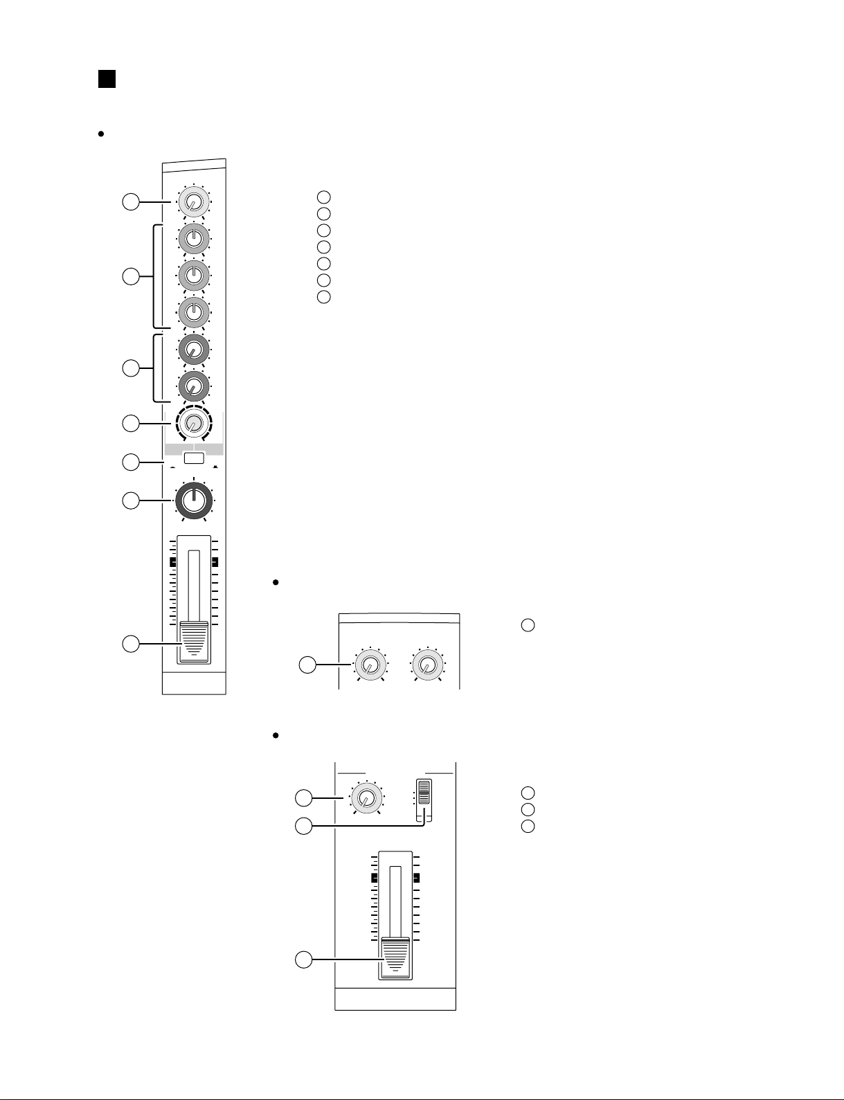
PANEL LAYOUT
Input channels
MT400
1
2
3
4
5
6
7
GAIN
LINE MIC
HIGH
–12 +12
MID
–12 +12
LOW
–12 +12
AUX
1
010
AUX
2
010
MIX CUE
010
MIC/LINE
to L
TAPE
PAN
10
9
8
7
6
5
4
3
2
1
0
TAPE
MIC/
LINE
INPUT-FLIP
LR
1
GAIN control
1
EQ control
2
AUX controls
3
CUE control
4
INPUT-FLIP switch
5
PAN control
6
Fader
7
Stereo Input
LEVEL controls
8
5L–6R
LEVEL
8
010
7L–8R
LEVEL
010
Monitor / Master Section
MONITOR/PHONES
LEVEL
9
MIN MAX
STEREO
ST+CUE
CUE
10
STEREO
10
9
8
7
6
5
4
3
2
1
0
11
MONITOR LEVEL control
9
MONITOR select switch
10
STEREO fader
11
5
MT400
Recorder Section
TAPE SPEED CONTROL
PITCH
–
ON
OFF
SYNC
16 17
12 13
4.8/ 9.5
+
ZERO STOP
ON
OFF
NOISE REDUCTION SYSTEM
14
3
2
1
OFF
OFF
R
L
OFF
OFF
R
L
METER SELECTREC SELECT
4TR4
STEREO
15
18
PITCH control
12
Tape speed switch
13
REC SELECT switches
14
METER SELECT switch
15
dbx switch
16
ZERO STOP switch
17
Tape counter
18
Counter reset button
19
Cassette compartment
20
19
20
Transport Section
REC PLAY REW FF STOP PAUSE
21 22 23 24 25 26
REC
button ( )
21
PLAY button ( )
22
REW button ( )
23
FF button ( )
24
STOP button ( )
25
PAUSE button ( )
26
6
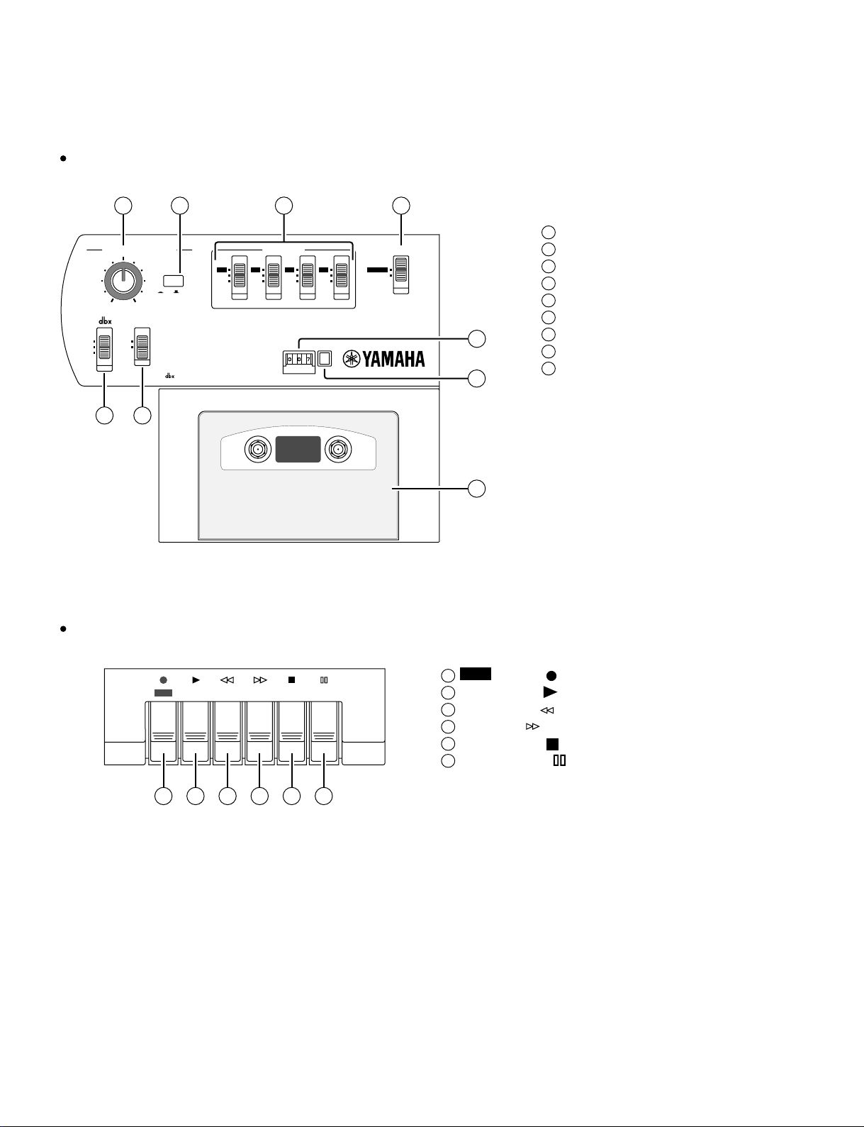
Meter Section
+6
+3
27
0
–5
–10
REC
28
Input / Output Section
MT400
Level meters
27
REC SELECT indicator
+6
POWER
+3
0
–5
–10
4
321
RL
29
28
POWER indicator
29
31 32
MIC/LINE INPUT
INSERT I/O
INSERT I/O
1
MIC/LINE INPUTs 1-4
30
INSERT I/O
31
STEREO INPUTs
32
AUX SEND
33
Front Panel
2
34 35
PHONES PUNCH I/O
Rear Panel
DC 12VPOWER
ON/ OFF
30
33
3
4
PHONES
34
PUNCH I/O
35
5
L6R
STEREO INPUT
8
R
7
L
SYNC OUT MONITOR OUT STEREO OUT
AUX SEND
1
2
RLRL
36 37 38
POWER ON/OFF switch
36
DC 12V
37
SYNC OUT
38
MONITOR OUTs
39
STEREO OUTs
40
39 40
7
MT400
CIRCUIT BOARD LAYOUT
MIX 1/3
SUB 1/3
MIX 2/3
SUB 2/3
REC 1/2
MIX 3/3
SUB
3/3
REC 2/2
8
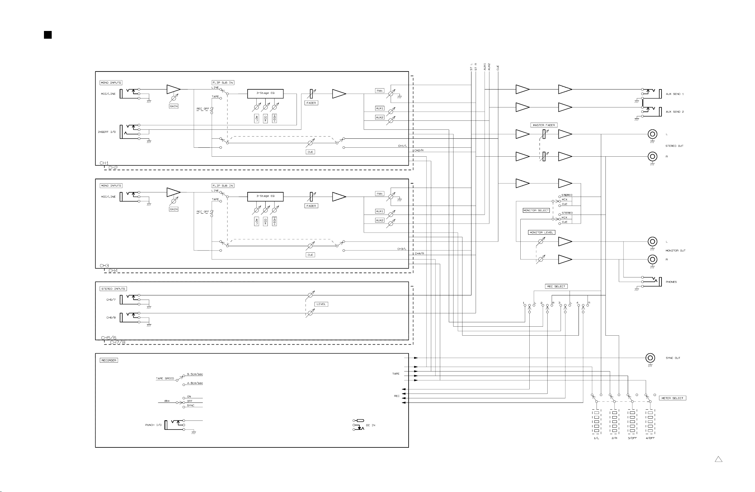
BLOCK DIAGRAM
IC101
31
IC103
27
IC104
31
21 67
IC106
MT400
IC201
31
IC303
27
IC105
31
21 67
21 67
21 67
21
IC107
IC108
IC109
IC110
IC110
67
31
IC111
67
MT400-3000 0
9
MT400
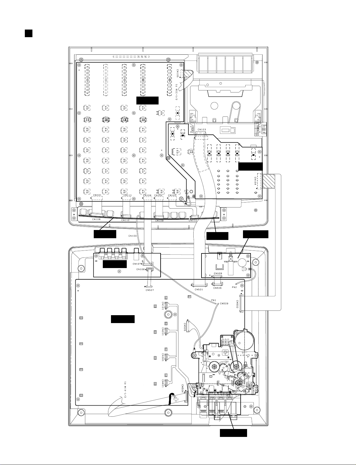
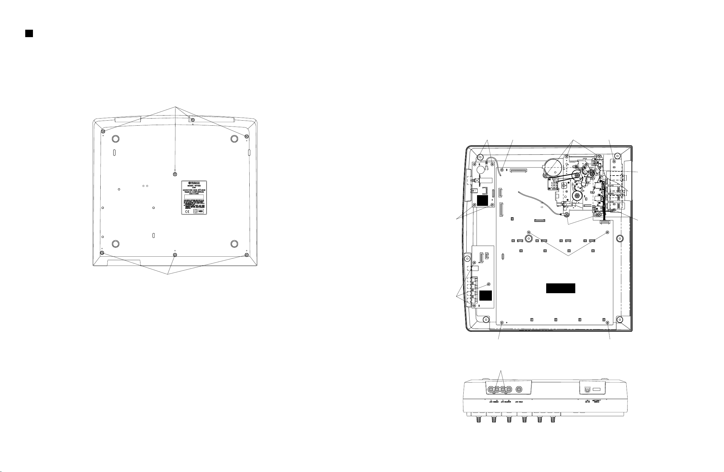
DISASSEMBLY PROCEDURE
1. Lower Case
1-1 Remove the seven (7) screws marked [320]. The
lower case can then be removed. (Fig.1)
[320]
〈
REAR
4. SUB 2/3, 3/3 Circuit Boards
4-1 Remove the lower case. (See Procedure 1.)
4-2 Remove the three (3) screws marked [320d] and
the two (2) screws marked [320e].
The SUB2/3 circuit board can then be removed.
〉
(Fig.2, Fig.3)
4-3 Remove the four (4) screws marked [320f]. The SUB
3/3 circuit board can then be removed. (Fig.2)
[320f] [320b] [320a] [320c]
SUB
3/3
[320f]
[320b]
[320c]
[320a]
2. Cassette Mechanism
2-1 Remove the lower case. (See Procedure 1.)
2-2 Remove the five (5) screws marked [320a]. The
cassette mechanism can then be removed. (Fig. 2)
3. REC 1/2, 2/2 Circuit Boards
3-1 Remove the lower case. (See Procedure 1.)
3-2 Remove the cassette mechanism. (See Procedure 2.)
3-3 Remove the six (6) screws marked [320b]. The REC
1/2 circuit board can then be removed. (Fig.2)
3-4 Remove the two (2) screws marked [320c]. The REC
2/2 circuit board can then be removed. (Fig.2)
〈
[320]
[320]: Bind Head Tapping Screw-P 3X10 MFZN2BL (EP630660)
Fig.1
FRONT
〉
〈
REAR
〉 〈
[320b]
REC 1/2
Fig.2
〈
Bottom
[320b]
〉
[320d]
SUB
2/3
[320b]
[320e]
FRONT
〉
10
〈
Top
Fig.3
〉
11A
2
3
4
5
6
7
1Y
2A
2Y
3A
3Y
V
SS
8
9
10
11
12
13
14
V
DD
6A
6Y
5A
5Y
4A
4Y
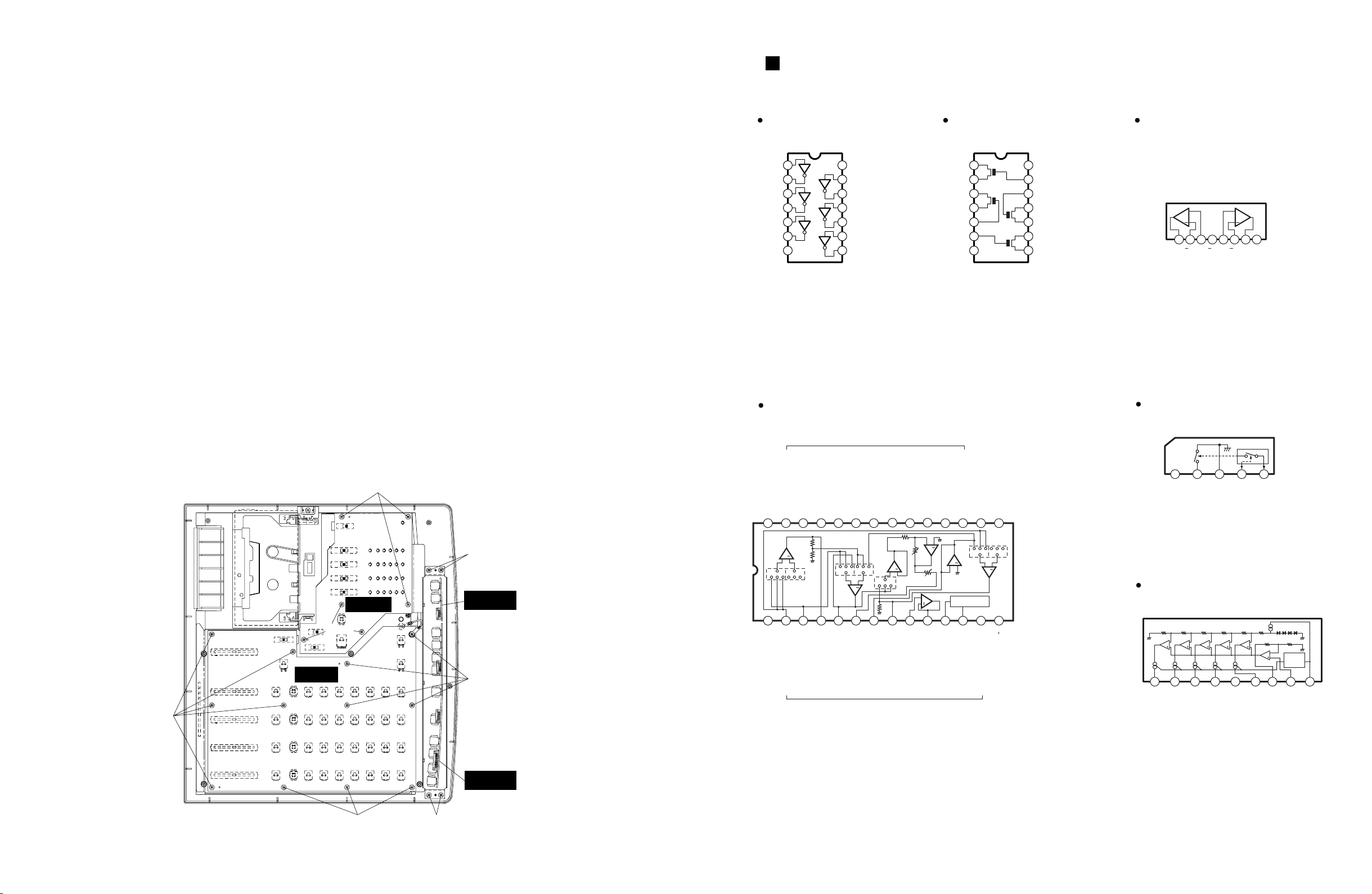
TC4069UBP(IG001720)
Hex Inverter
1Input (Output)1
2
3
4
5
6
7
Output (Input)1
Output (Input)2
Input (Output)2
Control2
Control3
V
SS
8
9
10
11
12
13
14
V
DD
Control1
Control4
Input (Output)4
Output (Input)4
Output (Input)3
Input (Output)3
TC4066BP(IX631591)
Quad Bilateral Swich
BA7755A(XH519A00)
Head Switcher
BA6137(XA534A00)
LED Driver
AN6292NK(XJ637A00)
Dual dbx NR
NJM2068LD(XM356A00)
NJM4558L(IX614610)
M5216L(XB419A00)
M5218AL(XH471A00
)
Dual Operational Amplifier
1A2 3 4 5 6 7 8
IN V
+IN
OUT
AAA
+VIN
+IN
OUT
BBB
+
B
+
1 2 3 4 5
VCC SW GND CTRL1CTRL2
D1
+ + + + +
+
Constant
Current
Circuit
1D22D33D44
GND5D56Amp
Output
7IN8
V
CC
9
3
8
9
20
21
26
ENPHASIS
BAND PASS FILTER IN
REC OUT
1
28
GND
+
2
27
R/P IN R/P IN
ENPHASIS
4
LINE OUT LINE OUT
5
24
ENPHASIS ENPHASIS
6
23
CCA-A OUT CCA-A OUT
7
22
CCA-B IN CCA-B IN
BAND PASS FILTER IN
REC OUT
10
19
BAND PASS FILTER OUT BAND PASS FILTER OUT
11
13
1618
LEVEL SENSOR IN
TIMING CURRENT ADJ.
LEVEL SENSOR IN
12
17
TIMING CAP. TIMING CAP.
DECODE / ENCODE SW
14
15
SW
B CH.
A CH.
+
DE
OFF
LINE AMP.
OFF
EN ENDE
+
+
+
DE
OFF
BUFFER
EN
EN
OFF OFF
DE DEEN
+
EN
CCA-B
CCA-A
REC OUT
AMP.
OFF
LEVEL SENSOR
OFF
DE DEEN
+
+
EN PHASIS
AMP.
25
5. SUB 1/3 Circuit Board
5-1 Remove the lower case. (See Procedure 1.)
5-2 Remove the PITCH knob of the TAPE SPEED
CONTROL on the upper case and the six (6) screws
marked [320g].
The SUB 1/3 circuit board can then be removed.
(Fig.4)
6. MIX 1/3 Circuit Board
6-1 Remove the lower case. (See Procedure 1.)
6-2 Remove the SUB 1/3 circuit board. (See Procedure 5.)
6-3 Remove the knob on the upper case and the twelve
(12) screws marked [320h].
The MIX 1/3 circuit board can then be removed.
(Fig.4)
7. MIX 2/3, 3/3 Circuit Boards
7-1 Remove the lower case. (See Procedure 1.)
7-2 Remove the four (4) screws marked [320I] on the
plate. The plate with the MIX 2/3 and 3/3circuit
boards can then be removed. (Fig.4)
7-3 Remove the holding plate of each jack. The each
circuit board can then be removed.
MT400
IC BLOCK DIAGRAM
〈
FRONT
[320h]
〉
[320g]
[320i]
SUB 1/3
[320g]
MIX 1/3
MIX 3/3
〈
REAR
[320h]
〉
MIX 2/3
11
Fig.4
[320h]
[320i]
MT400
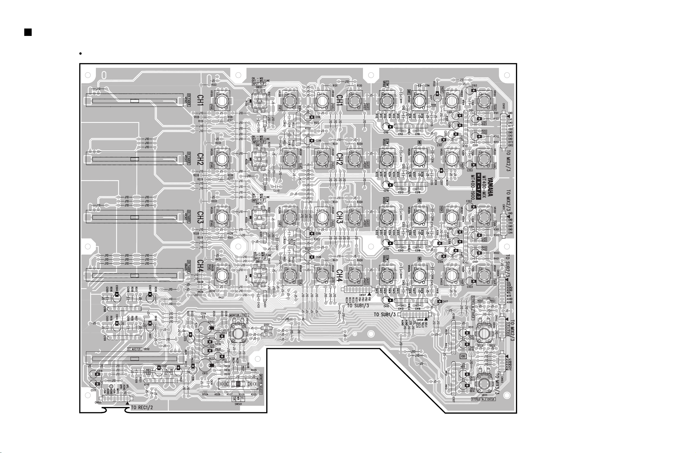
CIRCUIT BOARDS
MIX-1/3 Circuit Board
to MIX 2/3-CN108
to SUB 1/3-CN101
to MIX 2/3-CN112
to SUB 2/3-CN107
to MIX 2/3-CN109
to MIX 3/3-CN110
to SUB 1/3CN102
12
to REC 1/2-CN504
Component side
MIX : MT400-3400
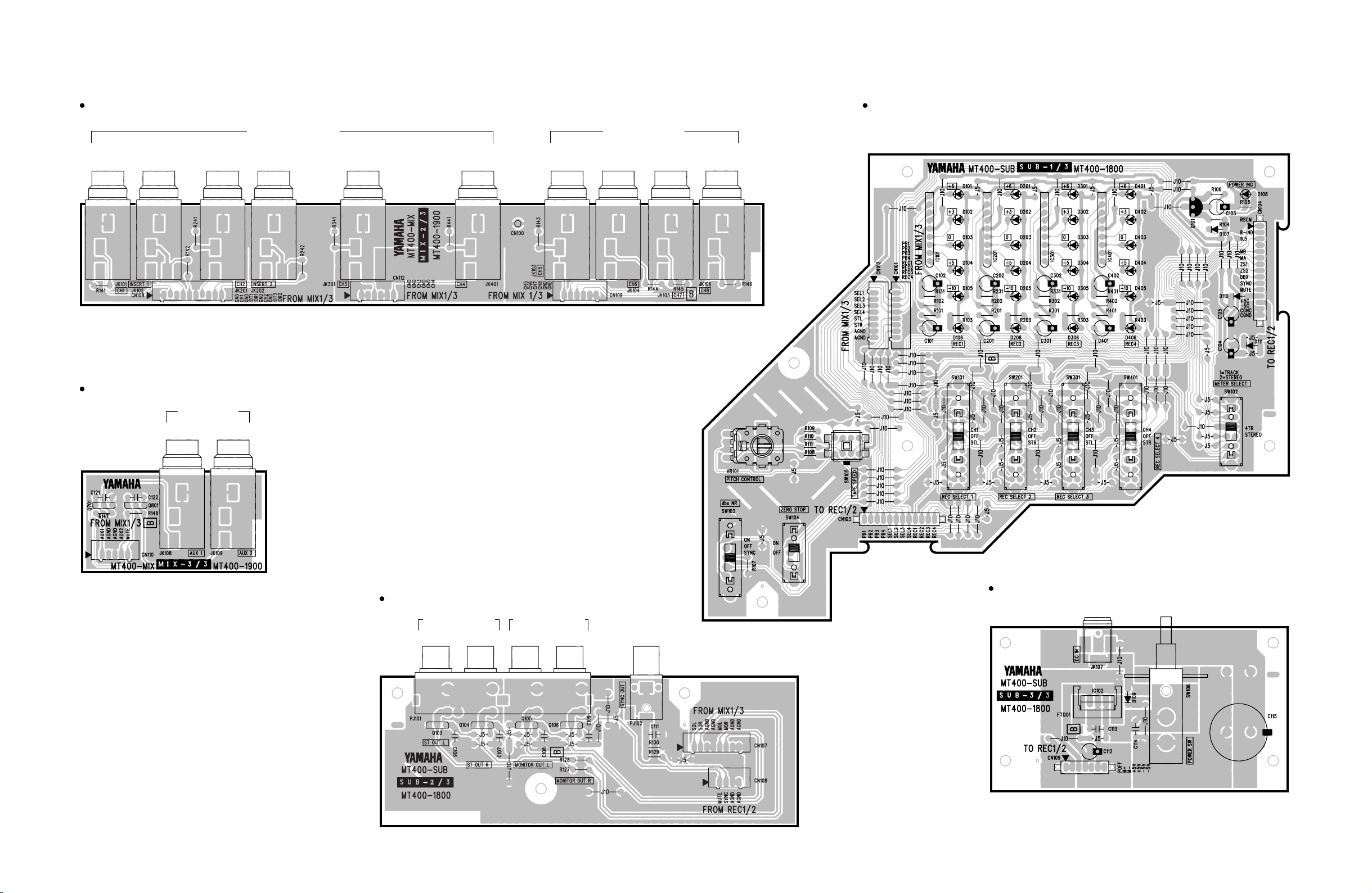
to REC 1/2-CN506
DC IN POWER SW.
to REC 1/2-CN501
to REC 1/2
-CN502
from MIX 1/3
-CN106
from MIX 1/3-CN107
MT400
MIX-2/3 Circuit Board
1-INSERT I/O
1 2 3 4 5L 6R 7L 8R
from MIX 1/3-CN101
MIX-3/3 Circuit Board
AUX SEND
12
MIC / LINE INPUT
2-INSERT I/O
STEREO INPUT
from MIX 1/3-CN111 to MIX 1/3-CN109
Component side
SUB-1/3 Circuit Board
from MIX 1/3-CN103
MIX : MT400-3400
SUB : MT400-3600
Component side
SUB-2/3 Circuit Board
STEREO OUT
LR
MONITOR OUT
LR
SYNC
OUT
from MIX 1/3-CN104
from REC 1/2-CN507
Component side
SUB-3/3 Circuit Board
Component side
Component side
13
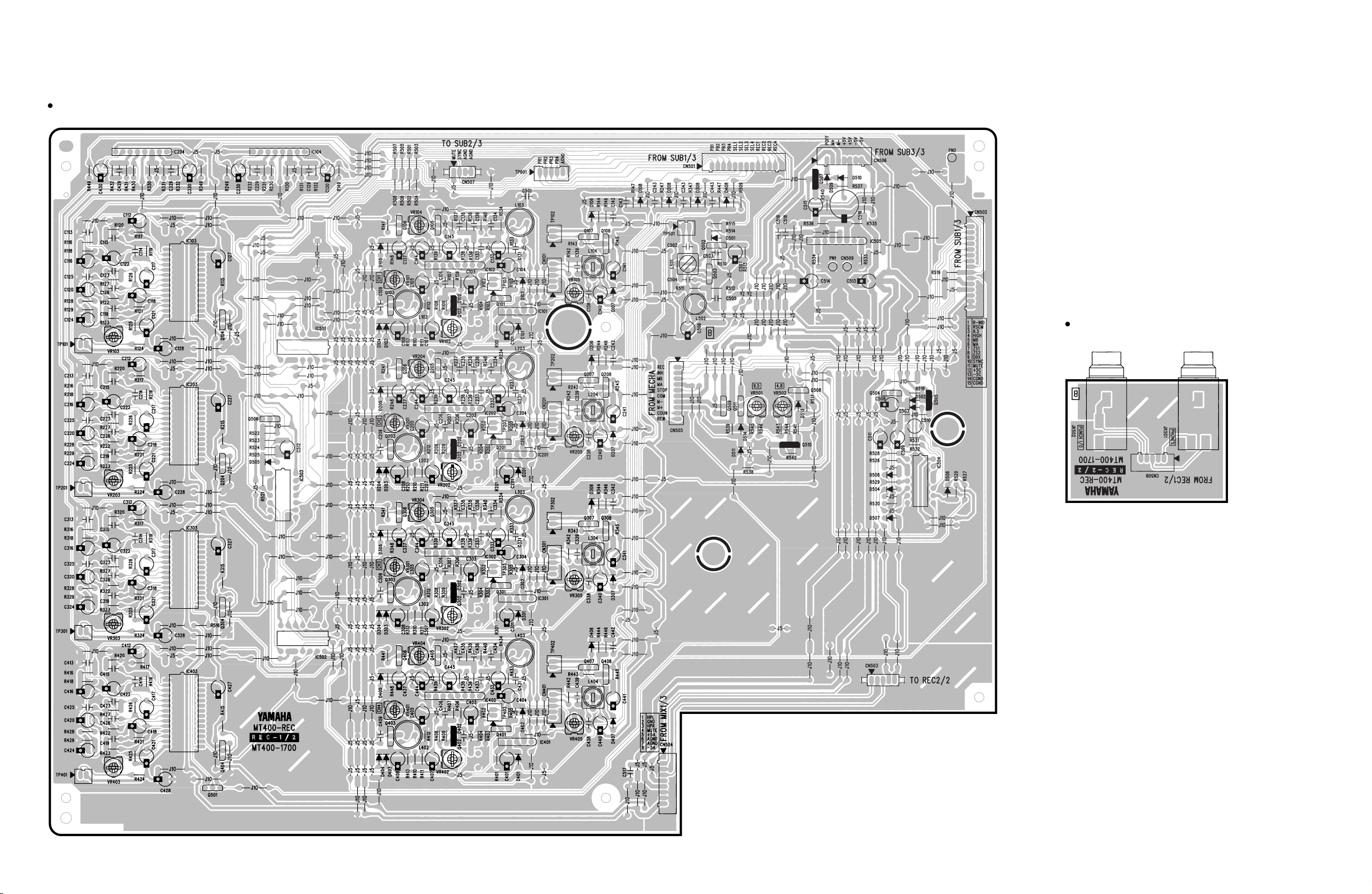
MT400
REC-1/2 Circuit Board
from SUB 3/3-CN109from SUB 1/3-CN103to SUB 2/3-CN108
from SUB 1/3-CN104
REC-2/2 Circuit Board
PUNCH I/O PHONES
from MIX 1/3-CN105
from REC 1/2-CN503
Component side
to REC 2/2-CN508
Component side
REC : MT400-3500
14
 Loading...