

Page 1
1
Table of Contents
What is mLAN Mixer? .......... 2
Starting mLAN Mixer........... 2
Windows98/95 environment. 2
Macintosh environment ........ 2
Top Panel Screen ................. 3
Menu Bar.............................. 4
File menu .............................. 4
View menu............................ 4
Option .................................. 4
Help menu ............................ 5
Basic Controls....................... 6
Control knobs ....................... 6
Numeric field box ................. 6
Input Channel Settings
(Input Section) ..................7
Master Track Settings
(Output Section) ............... 9
• The software and this owner’s manual are exclusive copyrights of Yamaha Corporation.
• Copying of the software or reproduction of this manual in whole or in part by any means is
expressly forbidden without the written consent of the manufacturer.
• Yamaha makes no representations or warranties with regard to the use of the software and documentation and cannot be held responsible for the results of the use of this manual and the software.
• Copying of the commercially available music sequence data and/or digital audio files is strictly
prohibited except for your personal use.
• The company names and product names in this Owner’s Manual are the trademarks or registered trademarks of their respective companies.
• The screen displays as illustrated in this Owner’s Manual are for instructional purposes, and
may appear somewhat different from the screens which appear on your computer.
Channel Tab Window.........10
EQ (Equalizer)...................... 11
Dynamics ............................11
Delay...................................12
Effect Tab Screen................13
System Tab Screen .............14
mLAN8P.............................. 14
mLAN8E .............................. 16
Block Diagram (Audio).......17
mLAN8P.............................. 17
mLAN8E .............................. 18
Data List..............................19
Effect Type .......................... 19
Effects Parameters................ 20
Dynamics ............................29
Dynamics Library................. 34
EQ Library ........................... 35
This owner’s manual assumes that you are already familiar with basic Windows/Macintosh operation. If you are not, please refer to the owner’s manual which came with
your Windows/Mac OS software before using mLAN Mixer.
For information about hardware requirements, the interconnection of devices and
the installation of the mLAN Mixer software, refer to the separate “Installation
Guide” as well as the owner’s manual for the respective mLAN device.
This owner’s manual is applicable to the mLAN Mixer for both Windows and Macintosh. The screen illustrations are mainly taken from the mLAN Mixer for Macintosh.
©2000 Y amaha Corporation
Page 2
What is mLAN Mixer?
mLAN Mixer is a software application that enables you to control the mixer functions of the mLAN8P/
mLAN8E from the computer as if you were controlling a normal mixing console. mLAN Mixer offers
independent EQ and dynamics settings for each channel, making it possible to perform detailed mixing
operation.
Starting mLAN Mixer
After installing mLAN Mixer and making the necessary connections, follow the steps below to start the
software.
Use mLAN Patchbay to set up the COM port for Windows.
Windows98/95 environment
In Windows98/95, select [Start | Program (P) | YAMAHA mLAN Mixer], then select “mLAN Mixer.”
Macintosh environment
Open the “YAMAHA mLAN Mixer” folder on the computer and double-click the “mLAN Mixer” icon.
2
Page 3
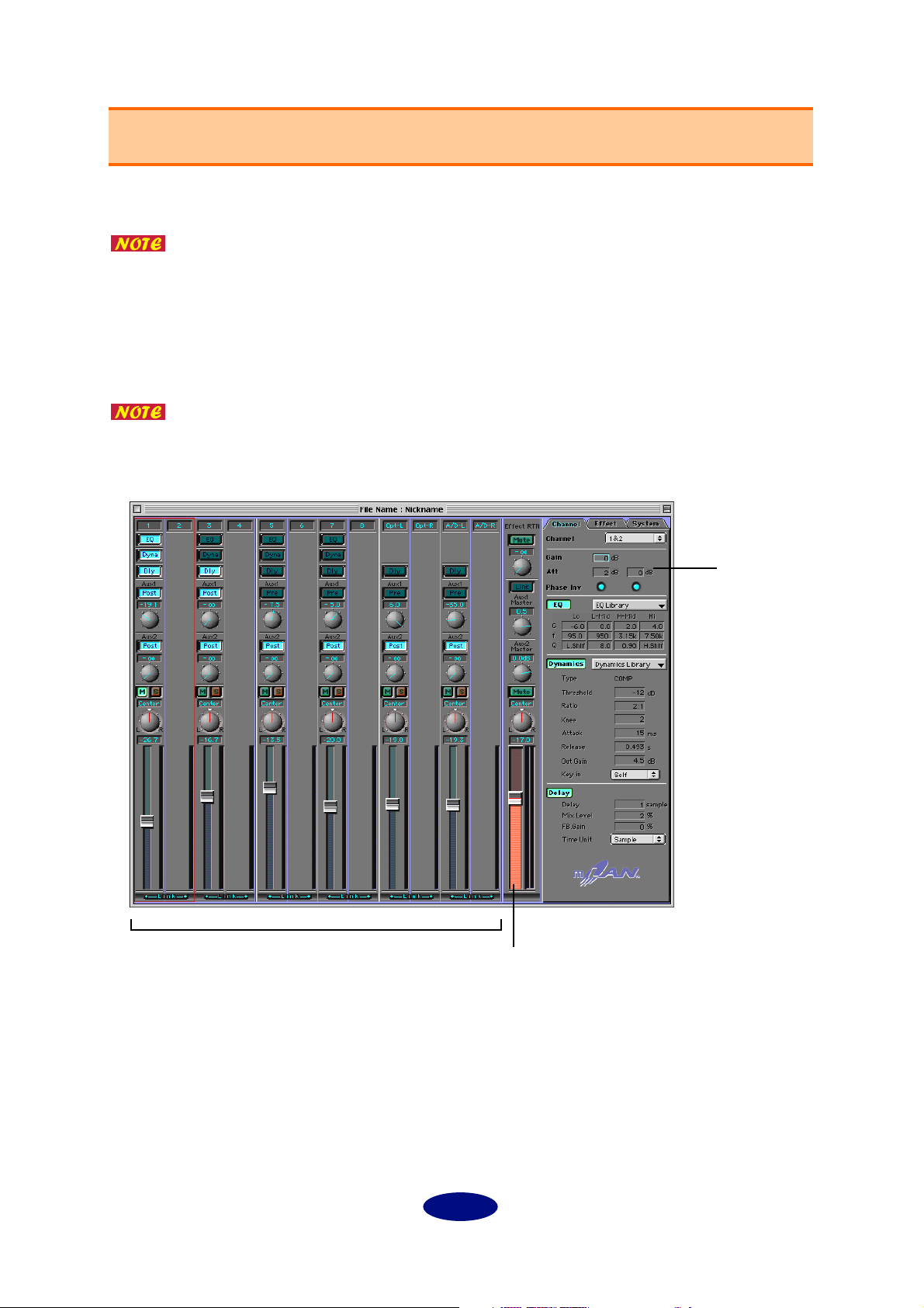
Top Panel Screen
The following screen appears when you start mLAN Mixer.
If there are multiple mLAN8P/mLAN8Es connected to the bus (system) of a Macintosh computer, a window appears, prompting you to select the device you wish to
control with the mLAN Mixer. You can select multiple devices to control simultaneously from the mLAN Mixer. If you are using a PC that runs Windows98/95, an
mLAN8P/mLAN8E connected serially to the computer will be automatically
selected.
The mLAN8P controlling screen and the mLAN8E controlling screen are slightly different. This manual references the mLAN8P controlling screen. However, functions
that differ are also explained.
input channels (input section)
parameters
master track (output section)
3
Page 4
Menu Bar
File menu
New: ......................... Creates a new Mixer file.
Open: ....................... Opens an existing Mixer file.
Save: ......................... Overwrites an existing file with the currently-edited Mixer file.
Save As: .................... Saves the currently-edited Mixer file with a different name.
Quit: ......................... Closes mLAN Mixer.
“Save” and “Save As” do not save the Level, Meter Source, Peak Hold, Fall Time,
and Word Clock settings.
The edited settings for the mLAN mixer will be lost when the power to the
mLAN8P/mLAN8E is turned off. (This does not apply to the parameters accessible
from the control panel of the unit.) Be sure to store the necessary settings using the
File menu.
View menu
Hide/Show Parameter: ............... Displays or hides various parameters in the tab screens.
Option
Init Channel (Initialize Channel): ......Opens the Init Channel dialog that is used to initial-
ize the settings for selected channels or all channels.
Preference (Windows only): ................Opens the Preference dialog that is used to customize
the menu shortcut keys.
4
Page 5
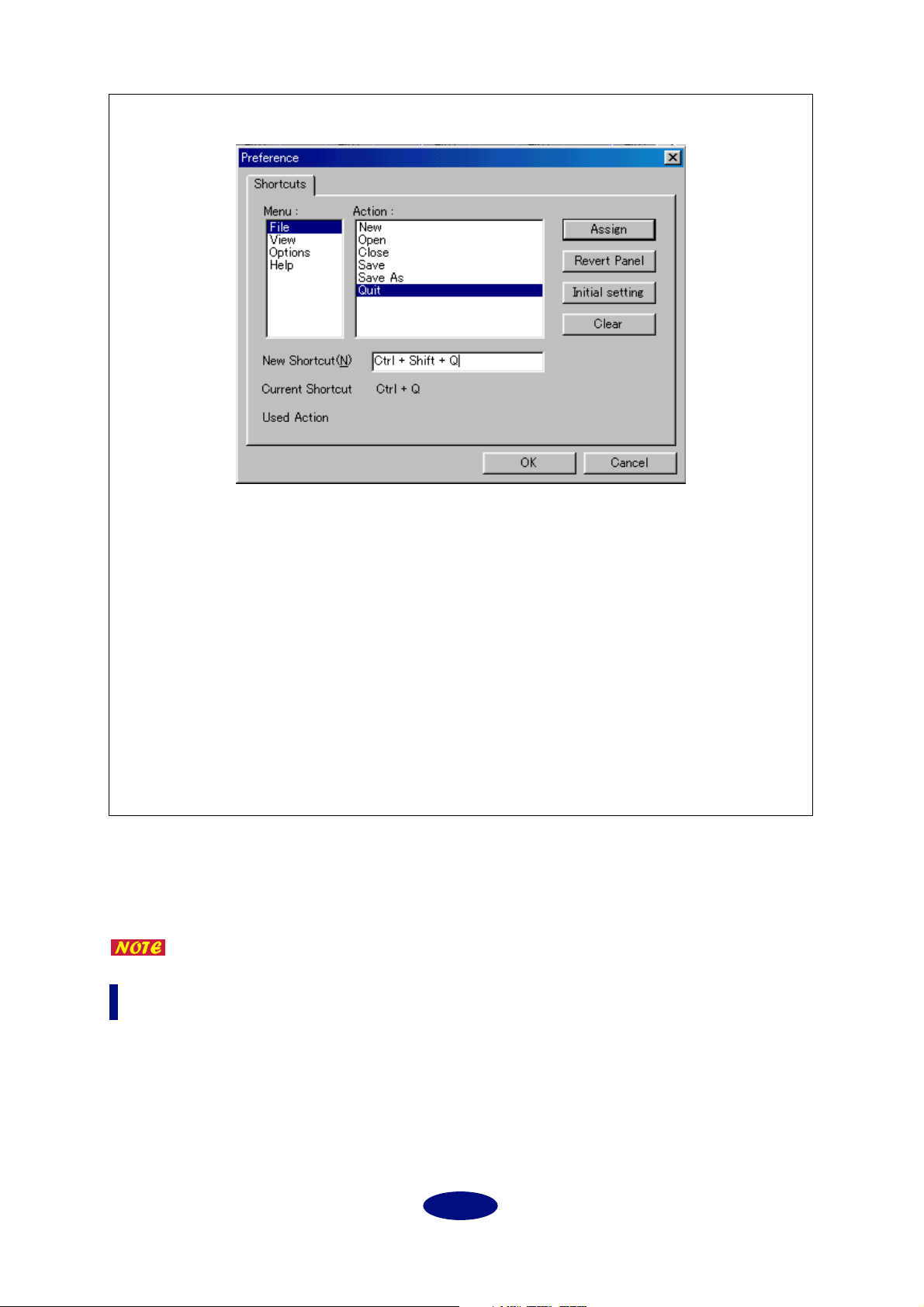
Preference dialog (Setting the shortcuts) (Windows only)
Shortcuts
1. Select a menu and action from the Menu and Action columns for which you wish to set
a shortcut. In the example above, [New] in the File menu is selected.
2. Click [New Shortcuts] and press the desired shortcut key. In the example above, the [Q]
key is pressed while the [Ctrl] and [Shift] keys are held down. If the shortcut key has
already been assigned to another “Action,” the “Used Action” column displays the name
of the “Action.”
3. Click [Assign]. The “Current Shortcut” column displays the selected shortcut.
4. Press the [OK] button to confirm the selected shortcut setting. If you do not wish to
change the setting, click [Cancel].
Revert Panel: ......... Returns to the previous setting.
Initial setting: ........ The shortcut is set to the [Ctrl] key plus the first letter of the
selected Action.
Clear: ...................... Clears the setting.
Direct Mode: ........... You can temporarily place mLAN Mixer in Direct mode while you are
controlling the mLAN8E. This function is not available with the
mLAN8P.
Refer to the Owner’s manual for the mLAN8E for more information on Direct mode.
Help menu
About mLAN Mixer (A): ............ Displays the version information for the mLAN Mixer
(Windows).
5
Page 6
Basic Controls
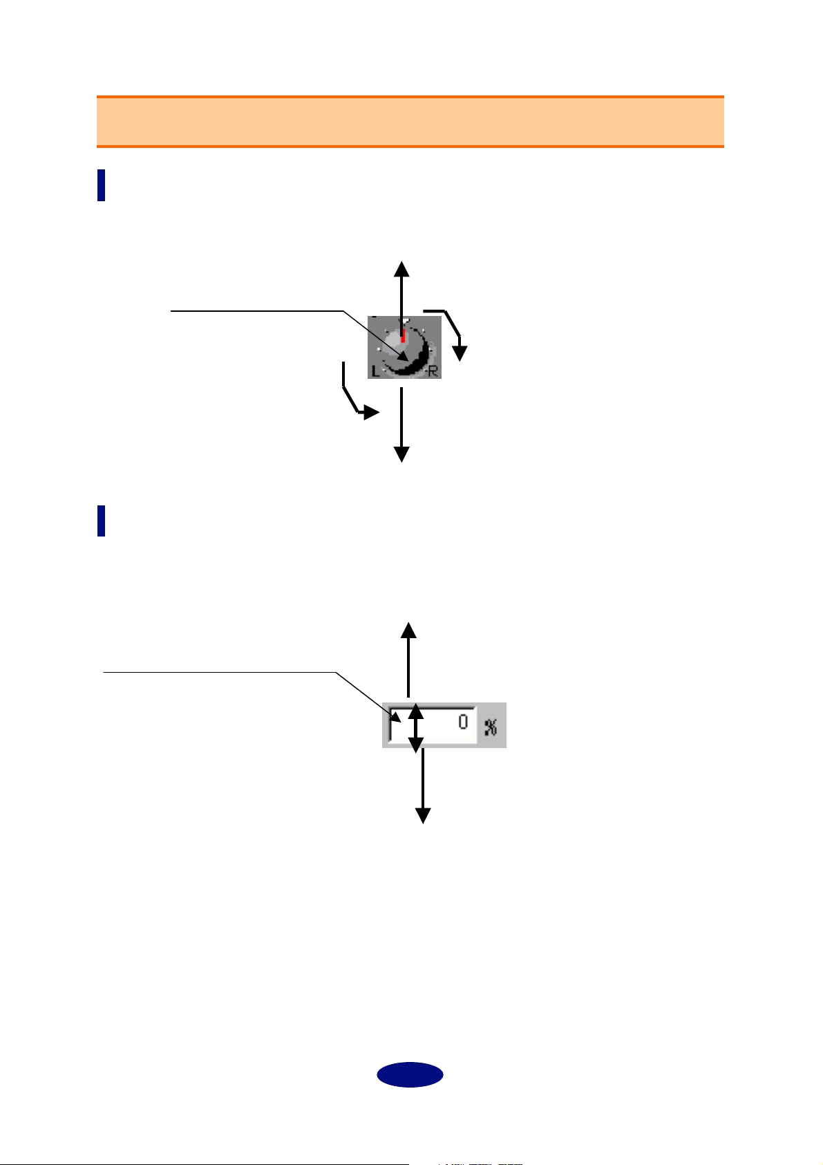
Control knobs
To rotate a control knob clockwise, click-and-hold the mouse on the knob while dragging upward. Drag
down to rotate the knob counter-clockwise.
Click-and-hold the mouse
on a control knob.
Move the mouse upward to rotate
the knob clockwise.
Move the mouse downward to rotate
the knob counter-clockwise.
Numeric field box
Click-and-hold the mouse and drag upward in a number box to continuously increment the value.
Drag the mouse downward to decrement the value.
You can also enter the value directly by clicking (double-clicking) the box.
Click-and-hold down the mouse button
in the box.
(The pointer changes to an arrow.)
Drag the mouse downward to continuously decrement the value.
Drag the mouse upward to continuously increment the value.
6
Page 7

A
B
C
D
E
F
G
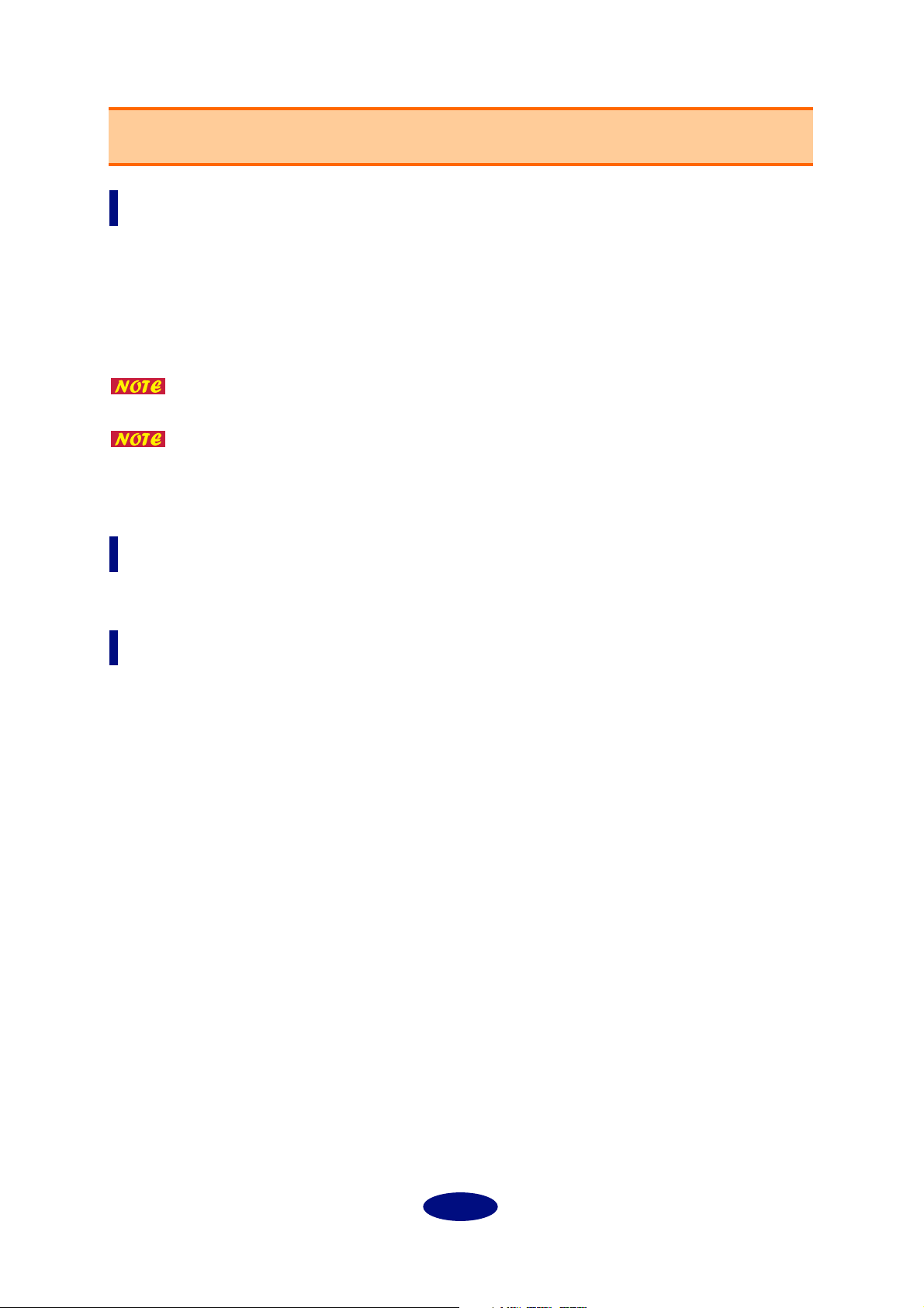
Input Channel Settings (Input Section)
You can adjust the input signal level and effect on/off for each channel.
Channel number
Channels 1-8 are used for input signals via mLAN. Channels 9 and 10 are
used for Digital input signals, and channels 11 and 12 are used for A/D
input signals.
EQ/Dyna (Dynamics)/Dly (Delay) button
These buttons are used to switch EQ, Dynamics, and Delay on and off for
each channel. The settings are linked with the buttons in the Channel tab.
Aux 1/2 send knobs
These knobs are used to adjust the level of each channel signal sent to
AUX 1/2.
Use these knobs when you are sending signals to an external effect processor or when you are monitoring signals with a balance that is different
from the stereo output balance.
If you are using the mLAN8P: Signals sent to AUX2 are also sent to the
internal multi-effect processor.
When AUX Layer is turned on, you can set AUX 3-6
parameters (mLAN8E).
Pre/Post buttons
These buttons enable you to select a pre-fader (Pre) signal or a post-fader
(Post) signal as the AUX send signal. With the “Pre” setting, a signal is
sent to the AUX bus before it reaches the channel fader; thus the signal is
not affected by the channel fader setting. With the “Post” setting, a signal
is sent to the AUX bus after it passes through the channel fader; thus the
signal is affected by the channel fader.
M (Mute) button
Press this button to mute the corresponding channel signal.
S (Solo) button
Press this button to monitor the corresponding channel signal.
Press this button while holding down the Shift key to monitor multiple
channel signals.
Panpot knob
This knob enables you to set the stereo position of the corresponding
channel. If the channel’s Link switch is set to “ON,” the knob adjusts the
signal balance.
You can set the attenuation and phase independently for each channel, even when
the Link switch is turned on.
When adjacent channels are linked, the panpot knob enables you to adjust the level
balance between the odd and even channels.
7
Page 8

H
I
J
Channel fader
The channel fader enables you to adjust the channel level. Click and hold
down the mouse button on the fader and slide the mouse up and down,
or click a desired point on the fader to move the fader to that point.
Channel level meter
The channel level meter is displayed on the right side of the channel
fader. The channel meter source is always the signal just after the gain, so
the channel level meter displays the level of the input signal and is not
affected by the EQ, Dynamics or the fader.
Link (Link switch)
When this switch is turned on, adjacent channels (1 and 2, 3 and 4, etc.)
are linked to each other for stereo operation.
8
Page 9

A
B
C
D
E
F
G
H
Master Track Settings (Output Section)
In this section, you can set the stereo out fader, AUX master level, and effect return level.
Mute button (mLAN8P only)
Press this button to mute the return signal from the internal multi-effect
processor.
Effect RTN (mLAN8P only)
This knob adjusts the amount of signal processed by the effect processor
and routed to Stereo Out.
The mLAN8E features an AUX Layer button instead of this
button. When you turn this button on, you can set AUX 3-6
parameters for both input channels and the master track.
Link button
Set this button to ON to link the AUX 1 and 2 settings. When they are
linked, the panpot setting of the corresponding input channel is used.
This is useful when you wish to use AUX 1 and 2 as individual stereo
outputs.
AUX 1/2 Master
These are used to adjust the level of the AUX 1 and 2 return signals.
When AUX Layer is turned on, you can set AUX 3-6 parameters (mLAN8E).
Mute button
Press this button to mute the stereo mix output.
Balance
This knob adjusts the left and right balance of the stereo mix output.
Stereo mix fader
This fader adjusts the level of the stereo mix signal. Click-and-hold the
mouse on the fader and slide the mouse up and down, or click the
desired point on the fader to move the fader to that point.
Level meter
The level meter is displayed on the right side of the fader. The meter
source signal is specified by the Mix Meter Source parameter.
9
Page 10

A
Channel Tab Window
mLAN Mixer offers the parameters independently for each channel, making detailed mixing operations
possible.
Channel (Target Channel)
Select the channel you wish to set here.
Click the desired input channel module
to display the corresponding channel
number here automatically.
Gain
This parameter enables you to adjust
the input level in steps of 6dB.
Internally, mLAN Mixer performs a Bit
Shift process.
Settings: –12 – +24dB
B
C
D
Att (Attenuator)
This parameter enables you to set the
input level in steps of 1dB. In this way,
you can fine tune the Gain value.
Settings: –96–+24dB
Phase Inv (Inverted)
Click the check box to reverse the phase
of the input signal.
10
Page 11

E
F
G
H
I
J
K
L
EQ (Equalizer)
EQ button
This button turns the selected channel EQ on or off. It is linked to each channel’s EQ button.
EQ Library
This parameter enables you to select a preset EQ type.
G (dB)
This parameter sets the amount of boost (+) or cut (–) of the signal at the specified frequency (F (Hz)).
Settings: –18–+18dB (in steps of 0.5dB), ON/OFF (only when [HPF] or [LPF] is selected for the
“Type” parameter with the Macintosh version.)
F (Hz)
This parameter sets the equalizing frequency.
LO: ................... 21 (Hz) – 20.0 k(Hz)
L-MID: ............ 21 (Hz) – 20.0 k(Hz)
H-MID: ........... 21 (Hz) – 20.0 k(Hz)
HI:
.................... 21 (Hz) – 20.0 k(Hz)
Q
This parameter sets the frequency range for boost and cut. The higher the value is, the smoother the
changes in the specified frequency range. With the Macintosh version, use this parameter to make
the setting for “Type.”
Settings: 10.0–0.10
Type (Windows only)
This parameter enables you to select a type of EQ.
With the Macintosh version, set the Q value (
select a Type.
[LO]
PEAK (peaking):
LSLV (low-shelving): A shelving-type equalizer that boosts and cuts the signal in the low range.
LPF (low pass filter): A filter that cuts the frequency range above the threshold specified by the “F
[HI]
PEAK (peaking):
HSLV (high-shelving): A shelving-type equalizer that boosts and cuts the signal in the high range.
HPF (high pass filter): A filter that cuts the frequency range below the threshold specified by the “F
mLAN Mixer uses a 4-band full parametric equalizer. Basically, a parametric equalizer changes a tone by boosting (+) or cutting (–) the signal at the specified frequency. Boosting emphasizes the corresponding frequency range, and cutting
attenuates the range. mLAN Mixer offers many presets suitable for various applications. Select one that suits your application, and fine tune it for quick operation.
A normal parametric equalizer
(frequency)” parameter.
A normal parametric equalizer
(frequency)” parameter.
) to the maximum or minimum to
9
Dynamics
Dynamics button
This button turns the dynamics processor of the selected channel on or off. This button is linked
with each channel’s Dynamics button.
Dyna (Dynamics) Library
Select the desired Dynamics type (page 34).
11
Page 12

M Ty p e
This field displays the type of dynamics selected in the Dyna Library field.
N Dynamics Parameters
These parameters are for the dynamics of the type indicated in the “Type” field (M). For more information, refer to Dynamics in the Data List on page 29.
O Key in (Key in Source)
You can set the ducking effect. Ducking is used for voice-over applications in which the background
music level is reduced automatically when the announcer speaks. For dynamics processing, match
the Key in the source parameter of the Target Channel (music channel) with that of the voice channel.
The input channel processors can be self-triggered (triggered by the signal to be processed), or they
can be triggered by a signal from another channel.
Dynamics processors are generally used to correct or control signal levels (like a
compressor) and psycho-acoustically extend the sustain. mLAN Mixer provides not
only a compressor but gates, limiters, and other types of processors for various
occasions.
mLAN Mixer offers many presets suitable for various applications. Select one that
suits your application, and fine tune it for quick operation.
Delay
This function is not available on the mLAN8E.
P Delay button
This button turns the selected channel Delay on or off. It is liked to each channel’s Dly (Delay) button.
Q Delay/Time (Delay Time)
This parameter sets the delay time.
Settings (sample): 1–9600 samples
Settings (millisecond): 0.023–217.687ms (44.1kHz), 0.021–200.00ms (48kHz)
R Mix Level
This parameter sets the mix balance between the dry sound and the delay sound.
With a setting of “0,” the ratio of dry signal to delay signal is 1:0. With a setting of “+50,” the ratio is
1:1. With a setting of “+100,” the ratio is 0:1. If the value is negative, the phase of the delay signal is
reversed.
S FB.Gain/FB. Level
This parameter sets the delay feedback amount.
This level is the amount of the delay signal fed back to the delay effect. With a setting of “0,” there is
no feedback. With a setting of “+99,” the feedback is at maximum. If the value is negative, the phase
of the delay signal is reversed.
T Sample
Select this option to display the delay time in sample units.
With 44.1kHz, one sample corresponds to 1/44,100 seconds. With 48kHz, one sample corresponds
to 1/48,000 seconds.
U MS (millisecond)
Select this option to display the delay time in ms (milliseconds).
Both options are based on either 1/44,100 seconds or 1/48,000 seconds, and feature
the same upper limit value. Select the desired option depending on your application.
12
Page 13

Effect Tab Screen
You can set the internal effect parameters on this screen. (mLAN8P only)
A Effect Mono Mix (Mono)
This parameter enables you to mix the L/R effect
return signals into a monaural signal.
B Effect Pan (Balance/Return Pan)
This parameter sets the L/R balance of the effect
return signals.
C Ty p e
This parameter enables you to select the desired
effect type (page 19).
D Use these parameters to set up the effect speci-
fied by the Type parameter. The displayed
parameters differ depending on the selected
(page 20).
effect
mLAN Mixer offers many presets suitable for
various applications. Select one best suits your
application, and fine tune it for quick operation.
13
Page 14

System Tab Screen
You can make settings related to the mLAN8P/mLAN8E on this screen.
mLAN8P
A Mixer Type
You can assign EQ and Dyna for up to eight channels. The assignments for channels 1-4 are fixed.
You can assign EQ and Dyna for the other four
channels here.
1: EQ and Dyna are assigned to channels 5-8.
2: EQ and Dyna are assigned to channels 5-6 and
Digital in.
3: EQ and Dyna are assigned to channels 5-6 and
A/D in.
4: EQ and Dyna are assigned to Digital in and A/
D in.
B Mix Meter Source (Level Meter Source)
This parameter enables you to select a signal to
display on the master track level meter.
Stereo Mix: Displays the stereo output signal.
Effect Return: Displays the effect return signal.
AUX1/2: Displays the AUX1/2 master output sig-
nal.
C Meter Setting
This parameter enables you to select the type of
level meter display.
Peak Hold ON: The meter holds the peak level
until you turn off “Peak Hold.”
Peak Hold OFF: The meter does not hold the peak
level.
Fall Time: This parameter sets the speed of the
meter’s response to the decaying sound.
Normal: Normal response speed
Fast: The meter responds quickly to and reflects
the attenuating sound. This setting clarifies the
attack level on the meter.
OFF: The level meter is not displayed.
D Digital Input
This parameter enables you to select Optical or
Coaxial for the input signal at the Digital In connector on the mLAN8P.
E Digital Output
This parameter specifies the signal routed to the
Digital Out connector on the rear panel of the
mLAN8P.
Settings: Stereo Mix, AUX1/2, Coaxial/Optical In,
A/D In
14
Page 15

F Analog Output
This parameter specifies the signal routed to the D/A out connector on the rear panel.
Settings: Stereo Mix, AUX1/2, Coaxial/Optical (depending on the Digital Input settings) In, A/D In
G Word Cl oc k
This parameter specifies the word clock for the mLAN8P.
Settings: Internal44.1k, Internal48k, Coaxial/Optical (depending on the Digital Input settings),
mLAN (follows the unit’s or mLAN Patchbay’s setting.)
H Device Fs
This field displays the actual sampling frequency.
The signal specified by the Analog Output source parameter is also output to connected headphones.
15
Page 16

mLAN8E
A Mixer Type
You can assign EQ and Dyna to up to eight channels.
1: EQ and Dyna are assigned to channels 1-8.
2: EQ and Dyna are assigned to channels 1-6 and
9-10.
3: EQ and Dyna are assigned to channels 1-4 and
9-12.
4: EQ and Dyna are assigned to channels 9-16.
B Mix Meter Source (Level Meter Source)
This parameter enables you to select a signal to
display on the master track level meter.
Stereo Mix: Displays the stereo output signal.
AUX1/2: Displays the AUX1/2 signal.
AUX3/4: Displays the AUX1/2 signal.
AUX5/6: Displays the AUX1/2 signal.
C Meter Setting:
This parameter enables you to select the type of
level meter display.
Peak Hold ON: The meter holds the peak level
until you turn off “Peak Hold.”
Peak Hold OFF: The meter does not hold the peak
level.
Fall Time: This parameter sets the speed of the
meter’s response to the decaying sound.
Normal: Normal response speed
Fast: The meter responds quickly to and reflects
the attenuating sound. This setting clarifies the
attack level on the meter.
OFF: The level meter is not displayed.
D Word Cl oc k
This parameter specifies the word clock for the
mLAN8E.
Settings: Internal44.1k, mLAN (follows the unit’s
or mLAN Patchbay’s setting.)
E Device Fs
This field displays the actual sampling frequency.
The signal specified by the Analog Output source parameter is also output to connected headphones.
16
Page 17

Block Diagram (Audio)
mLAN8P
LEVEL METER KEY IN
mLAN Plug Name
Input 3
Input 8
VOLUME
INPUT
1Input 1
2Input 2
mLAN
3
8
DIGITAL
INPUT
SELECT
SFC
DAC
DAC
GAIN PHASE DELAY4 BAND EQ DYNAMICSATT
GAIN PHASE DELAY4 BAND EQ DYNAMICSATT
9
10
11
12
Same as above,
except that the 4-band EQ and Dynamics processor can be assigned to up to eight channels.
KEY IN
EFFECT
LEVEL METER
AUX2 MIX R
AUX1 MIX L
LEVEL
ON
PRE/POST
PANPOT
SEND
DIGITAL OUTPUT
SELECT
AUX1
AUX2
MIX L
MIX R
ANALOG OUTPUT
SELECT
AUX1
AUX2
MIX L
MIX R
DAC
DAC
PHONES
VOLUME
LEVEL METER
OUT1
OUT2
AUX1
AUX2
MIX L
MIX R
PHONES
L/R
mLAN Plug Name
AUX1
AUX2
St Mix L
St Mix R
Dig In L
Dig In R
A/D In L
A/D In R
17
 Loading...