

Yamaha MJ50J Service Manual
8YAMAHA
SERVICE MANUAL
MANUEL
DJ\TELIER
5N7-28197-70
Particularly i
mpo
rta
nt in
formatloo
is dis·
ti
ngui
shed
in this manual
by
the
following
notations:
NOTE:
A NOTE provides key
information
to
make
procedures
easier
or
clearer.
~~~~
~
3
A CAUTION i
ndicates
special
procedures that
must be followed to avoid damage
to the
motorcycle
.
1'4
·
hfr"t'''
A WARNING i
nd
icates special
procedure
s
t
ha
t rnust be followed 10 avoid inj u ry
to
a
mo
torcycle
operator
or
person
inspecting or
r
ep
air
ing the mot
orcyc
le.
MJ50J
SERVICE MANUAL
FIRST
EDITION,
APRIL
1981
ALL RI
GHTS
RESERVED BY
YAMAHA MOTOR COMPANY,
LID
.
JAPAN
PRINTED
IN
JAPAN
Dans
cc
mJnuel, ks
informations
par
liculicre-
ment importantes
sont
repfr~
par
les nol
;J·
tion~
sui\'antt;S:
N
.IJ.
:
l"n
N.B
. fournil les informations en
rdpport
avec Je
s
r~prei;
pour
rendre l
es
proc<dures plus
fociles
ou
plus
claires.
::
1tI~til1~~
~
Un A
lTENTION
i
ndique
les
procedures
spt!cia
les
qui
doh•ent
t!tre
suivies pour Cvitcr
d)endonunagcr
la mo1o
cycle1te.
AVI
RJISSDIF.N
T
Cn AVERTISSEMENT i
ndique
les
procedures
sp<!cialeS
qui
dOi\'Ctlf
et
re
$1.
liV'i
E:S
pour
t':\'iter
un
acdc.Jen
t a J'u
tHJsateur
de
lti
motocyclcttc
OU a la pcrSOJlJlO
<OJ1trola11t
OU
rcparan
t
Ja
mo1ocyclelte.
~IJ50
J
~1.-\i'IUEL
D'ATELI
ER
PRE~
ILER£EDITI01'.AVRIL
1
981
TOUS DROITS
RESERVES PAR LA
YA~L~HA
)!OTO
R CQ)IPA1'Y. LTD.
J..\P01'
NJ>RJ.\IE AU J..\PO
:\
CONTENTS
IGNITION CONTROL SYSTEM
......
.
.........
.•
....•
......
A. Basic circuit diagram . . . . . . . . . . . . . . . . . . . . • . . . . . . . . . . . . . . 1
B. Operation . . . . . . . . . . . . . . . . . . . . . . . . . . . . • . . • . . . . . . . . . . . 2
C. Engine speed control
unit
checking. . . . . . . • . • • . • . . . . • . . • . . . 3
11 POWER FLOW
DIAGRAM
.....
..
....
.....
• .• •... . • . ..•.
••.
4
Ill
REAB
ARM
AND
REAR SUS!'ENSION
..
. • . . . . • . . • . . • • • . . . • . 6
A. A
ear arm
rernoval . . . . . . . . . . . . . . . . . . . . • . . • . . . . . . . • . . . . . 6
B.
Rea
r arm installat
ion..................
.... .
............
7
(VM
ISCELLANEOUS .
........
..................
............
8
A. Specifications . . . . . . . . . . . . . • . . . . . . . . . . . . • . . • . . . . . . . . . . 8
B. Cable routing
.....
. .
.....
..
•..
. .
.......
.
..............
18
C. Wiring diagram . . . . • . . . . . . . . . . . . . . . . . . . . . . . . . . . . . . . . . . 22
CONTENU
SYSTCMl:i
DE
COMMAND£
D'
ALLUMACE
.. ....
....
. . .... .
..
.
~
.
SchCrna
du
circuit
.....................
...........
.
...
.
8.
F'onctionnemen
l . . . . . . . . . . . . . . . . . . . . . . . . . . . . . . . . . . • . . 2
C.
Con
tr6
1 de l'unj
tt
de commandc de v
it\!SSC
du
moteur
. . . . . . . 3
II SCHEMA
Dt;
PASSAGE DE LA PUlSSA:"CE .
..
.. ....
...
...
4
llI BRAS ARRIERE EL
LA
SUSPENSION ARRIERE
..............
6
A.
Dtposc
de bras anierc . . . . . . . . . . . . . . . . . . . • • . • • . . . . . . . . . . 6
B.
Mon13ge de bras
anicrc ....
........
.....
..... .
IV
DIVERS
...
. .
J\,
C3rac1cristiqu
es. . . . . . .
.........
........
.... . .... .
Jl
. Chcmi
nel!l<'nt
des cables
........
..
• .
...•.
. . .
..
C.
Schema de cablase.
....
. ......•. .
.....
•.
. • . .
...•.....
13
13
IS
I
IGNITION
CONTROL
SYSTEM
The
MJSOJ
d
istinctly
indicates START and
RUN
on
the
main switch. The electric engine
spffd
control
unot
PfeYOnU
the
motorcycle
from lurching f0<ward due
to
the
roder"s
un·
skillf
ul
operation.
l'
·h1
flMll
__________ _
1.
Nevt:r
start the
tngine
or
!et
it
run for
any
1Cfl91h
of
time
in
1
cf~
area. T
he
exhaust fumes arc poiionous and can
cause
dea
th within 1
short
time. Always
operate
the
motorcycle
in
en
area
w
ith
adequate ventilation.
2.
Do
not
run
the
t:<l!Jina
unti
l you
know
the
mo
toteycle hH
vr10u9h
engi
ne
oil.
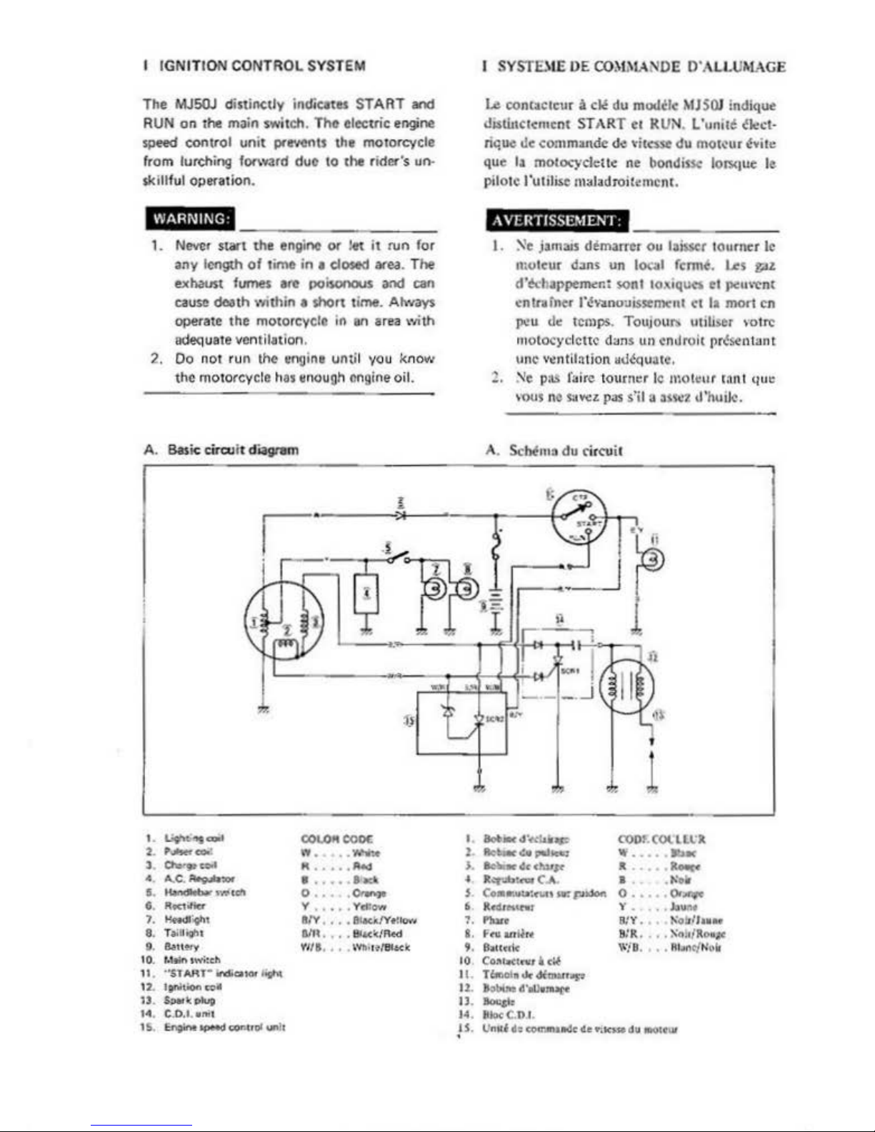
A.
Basic circu it diagram
'-
Li9"t.t'lf~
COLO"COOC
2.
,__
...
-
3
Cha...'9teoo•
"
··
-
•
... c.
........
..
'""
..
........,.,,wceft
o
..
°'-
G.
RKtilicr
Y , ,
...
VdJovr
1.
Hndl'
ttn
8(V , , , •
~.lYtHo"·
'
a.
r
.u~u
am
....
S.u</Rtd
9. &
lt
!f)'
Vl
/S,
'.
Wb+l
~IBl.K
lc
10.
t-Wnt
wi:
ch
11.
'"$l
AIU
"'
in!SCUOf
l'l!N
12.
ltf'lt
.ond
1J
.
s,.\..,.
...
C.0.1.•mt
IS
.
~J,pMCtc:oeuc'""·c
'·
l
).
'·
t.
'·
10
II
.
12.
tl
.
..
.
!S
·
I SVSTDlE DE
CO~L\IA
"llOE
D"ALLUMAGE
Le
contaclcur
a cle
du
mo1Wc
MJS
OI
indique
d1Sti11c1cmcnt
START
e1
RUN.
L'uml~
~i.,ct
rique
Uc
commande
de
\'itc:sst du
mol~ur
~-.ire
que
la
motocycleltc
ne
bondif'<
lors<1ue
le
pilo1c l"uldise maladroit•mcnt.
iiji;il6}18§11HM
____
_ _ _ _
I .
~e
jamais demarrcr
Ou
laisscr
tourner
le
mutcur
d>ns
un
loc3I fcrrne. Les
f;ll.
d\!chappem<r.t
wnt
IO\lqucs
el
"'""""t
cntr.rncr
l"t!Vl.nousss:emcnt
ct
11
mort
en
P<!U
de temps.
TouJOUI">
uu~.er
>o
trc
motocyclcttc d;ms
un
enJroit
pr~sen
t::int
unc
v•ntilalion aolequitc.
2.
Ne
pas
faire 1ourner le
mottur
cant
qua:
mus
nc
suvez
pas
s"i
l 3
3$S<%
d'hutlc.
A. Scbem3
du
rircuit
lot-.cd~lp
COOfCOllLU
9cbti1W(•,..Jtt:
...
...
ao-.r
t~
cJur~
JI
RO"C<
ltq\lb_C_.
I
trr:olf
eo
...
u:n.ct sr. pidotl. o
..
°"-
Rtdr
bt.nir
y .
.bU!"lt
l'hltc
S:Y.
t\o:.rfhue
F~antf:tf"
8
1R.
. .
X<\,1/RO•at
8.tC(l'k
W/8.
• • R...,c{K
olo
C011bttte'.'Q
ldf
T'->.ot•
Jir
dftzwr"P'
·-d'.U.JUte
lloush
81o<C.OI
IJndtl:ii~clllleirtk,.dw.otcw
B.
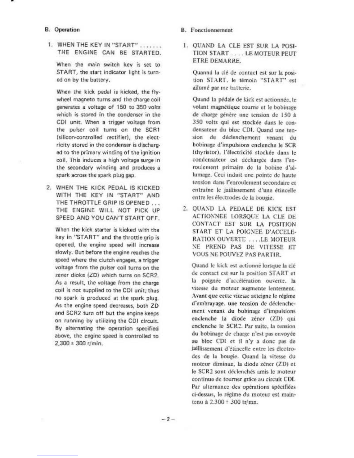
Operation
1. WHEN THE
KEY
IN
"START"'
.•..•••
THE ENGI
NE
CAN
BE
STARTED.
When the main switch
key
is
S(lt
to
ST
ART,
the start lndk:ator li
ght
is
turn·
ed
on
by
the
battery,
When
the
kick pedal is kicked,
the
fly.
wheel magneto
turns
and
the
charge coil
generatC$ a voltage
of
150
to
350
volts
which
is
stored
in
the
condcOS(lr in
the
COi
unit.
When
a
tri!l'J@r
voltage from
the
pulser coil
turns
on
the
SCR
l
!sili<:oo-controlled rectiller),
the
elect·
rtc
ity
stored
in the
condenser
is
discharg·
cd
to
the
primary winding
of
the
igniti
on
col
l.
This induces a high voltage surge in
the
secondary winding ,,nd produces a
spark
across
the
spark pl
ug
gap.
2. WHEN THE
KICK
PEDAL
IS
KICKED
WITH
THE
KEY
IN
"START"
AND
THE THROTTLE
GRIP
IS
OPENED ...
THE
ENGINE
WILL
NOT PICK UP
SPEED
AND
YOU
CAN'T
START OFF.
When the kic,k
starter
is kicked w
ith
the
key
in "'START"
and the
thrott
le grip is
opened,
the
engine speed will increase
slowly.
But before
the
engine reaches
the
speed where
the clutch
engages, a trigger
voltage
from
the
pulser coll
tums
on
the
zener dioke (ZDI
which
1urns
on
SCR2.
As
a result, the voltage from
the
charge
coil is
not
supplied
to the
COi
unit;
thus
no
spark
is
produc
ed
al
the
spark plug.
A• t
he
engine speed decreases,
both
ZD
and
SCR2
turn
off but the engine
keep
s
on running
by
utilizin~
the
CO
i
circuit
.
By
alternating
the
operation
specit
ied
above,
the
engine
speed
is
controlled
to
2,
300
•
JOO
r/min.
-2
-
B.
fonctionnement
I.
QUAND LA
CLE
!OST
SUR
LA
POSI-
TION START
....
LE
MOTEUR PEl!T
ETRE
DEMARRE.
Qu
311nd
I~
de
de
comac
t est
sur
la posi·
t
ion
STARl.
le
tem
oin
"ST1\RT"' est
allum~
par
m<
hauerie.
Qu11.rtd
la
pedale
de
kick est
acrionn~
c
.
le
\Ohmt
m~~tique
coume
ct
tc
bobinage:
~
char:;•
ginere
une
tension de 150 a
350
'"<>Its
qui
est
stocket
d•ns
le
con·
densoteur
du
bloc COi.
Quand
Un<
teo·
sion
de
declenchemcn t vonant
du
bobinagc d'impul<ions cnclenche
kl
SCR
(1hyristor). l"clectricit6 stockcc
dn
1" le
condcnsateur est dcchargcc d•ns l"en-
r
oulc11
1ent
pr
ima ire
de
la bobine d"ul·
lum:igc.
Ced
induit
unc
pointc de haute
tension
d:ms
l'c:uoulcmen1 sccondaire
ec
cntrafnc
le j>illissement
d'unc
~Linc.<lte
cntn:
lcs electrodes
de
la bougie.
1.
QUA'.\'D
LA
PEDALE DE
KICK
EST
ACl'IO!'\NEE
L.ORSQLll::
LA
CLE
Of.
CONT,\CT
EST
SUR
LA
rosJTJON
START
ET
LA
POIG'.'<EE
D"AC("ELE·
RATION
OUVERTE
....
LE
MOTEUR
:-<E
l'REND P ... S 01::
Vll'ESSE
ET
VOUS
'llf.
POUVJ:2
PAS
f'ARTI R.
Quand
I<
kick est
actionnc
lorsquc la clc
de
<'On tact
at
sur
la
po:.iti
on
ST A RT
et
b poiin<c d 'a<..:<!loration
ou«rr~
.
la
nh~~
du
moteur augmcnte lcnrement.
..\vane
que
c~ne \il
~>Se
aue
igne le
re,Pme
d'embrayate.
UM
r~nsion
de
d~clenc h
e·
mtnl
'
cnant
du bobinagc d"impulsions
cndcnchc
la diode zencr
(ZD)
qui
cnclencbc
le
SCR~.
Par snitc. la 1•nsion
du
bobinage
d~
chaii:c n'cst P"" enYOyee
au bloc COi
ct
ii
n'y a done
pas
de
iaiUl<sement d'<'tiocdlc
cntre les
~lcetro
·
des
de
la bougie. Quand la
•itcs.c
du
motcur
dim
inue.
la
diode
z~ncr
(ZDJ
ct
kl
SCR2
sonL
dedenches
amis le
motcur
con
tinue
de
toumer
gr3cc
au
circuit
C.:0
1.
P
ar
alternance des operations
s~cifiees
ci~des.swt,
le
regime
du
motcur est
main·
tcnu
~
2.300 • 300
tr/mn.
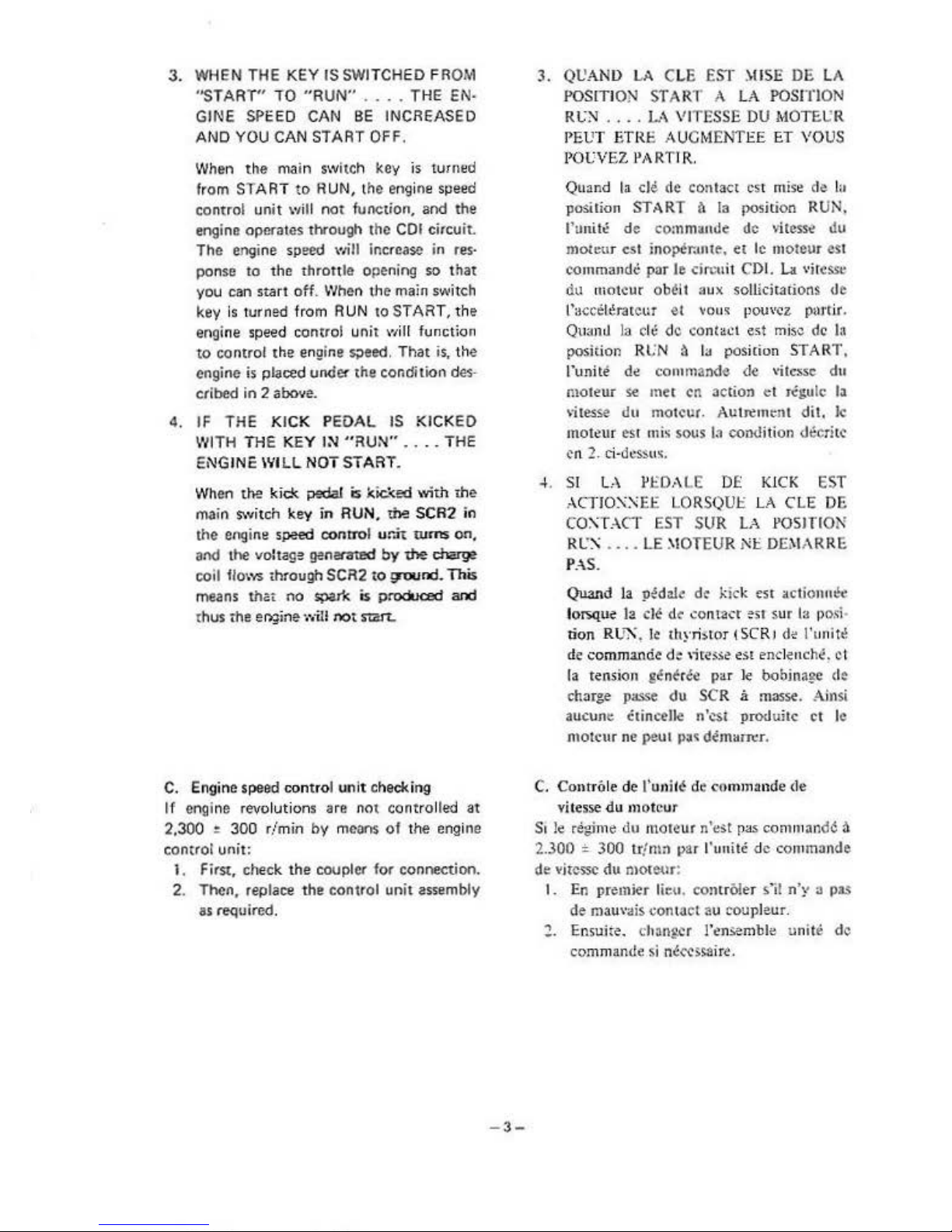
3.
WHEN THE
KEY
IS SWITCHED FROM
"START"
TO
"RUN"
....
THE EN·
GINE SPEED
CAN
BE
INCREASED
AND
YOU CAN START OFF.
When
the main switch key
is turned
from STA
RT
to
RUN, t
he
eng
ine speed
control
un
it
\'li
ll
not
function, and
the
engine
operates
through 1he COi circuit.
The
engine speed will increase in res·
ponse
to
the
throttle
opening
so
that
you
can
start
off. When t:he main switch
key is turned from R
UN
to
ST
ART, the
engine
speed
control unit will function
to
contro
l the engine
s;>eed.
That is, the
engine
is
placed
under
1he condition des·
cribed
in 2
above.
4.
IF
THE KICK PEDAL
IS
KICKED
WITH
THE KEY IN "
RUN" •...
THE
ENGINE WILL NOT START.
Wh
en
the
kick
pedal
is
l<ic.~ed
wi
th
The
main switch
key
in
RUN. the
SCR2
in
the
engine speed
contr0I unit
wms
on,
and the voltage genenrmd
by
the
charge
coil flows through
SCR2
to
!:l"O'Jnd.
This
means
that
no
spar'
~
is p
roduced
and
thus the
e
r>~in
e
·
j••il! not start.
C. Engine
speed
contro
l un
it
checking
If engine revol
ution
s are not
cont
rolled
at
2,300 •
300
r/min
by
means
of
the eng ine
control unit:
1.
FirSt, check
the
coupler for connection.
2.
Then,
replace
the
control
unit assembly
as required.
-
3-
3.
QL'AN
I>
LA
CLE EST
~llSE
DE
LA
POSITION START A LA
POSfflON
Rt.:'.'I
....
1-
.\
VITESSE
DU
MOTE.L'R
PEL'
T ETRE A UCMEN
TEE
ET
\'O
US
POUVEZ
l'ARTIR.
Quand la
cle
de
contact
est
miso
de
la
position START
~
la
p<>sition
RUN.
runiti!
de
co:nmande de
v
itess~
du
moteur est
ino;>er.mte.
et
le
moteur
est
commandC
par
Je
drcuit CDI.
La
"He
ss.:
du
mot
cur
ob~
i
I
aux
sollicitations de
l'accelerate1>r et
vou•
pou,·cz
pu1·tir.
Qu•n~
la ch! de cont
ott
est
misc de la
po
sition Rl:N ~ la
pos
ition START.
runite
d~
commande de. \'ilcs.sc du
moteur
se
met en action
et
rCgu
lc
la
vitesse du motcur. Autremr.nt
dit.
Jc
moteur
es1 mis
sous
la
condition
d~rhc
en
2. ci·
dcssu
s.
4. SI LA
l'J::O,\LE DE: KICK
EST
..\CTIOX:>iEE
LORSQUJ::
LA CLE DE
CO:\T ACT
EST SUR
LA
l'OSlTION
RL'l\ •.
•.
LE
~!OTEUR
NI::
DEMARRE
P . .\S.
Quand
la
p;dak
de
kick
est actionm!e
l
orsqu~
la
clC
de ..:onlaa
est sur
1:1
p
osi
-
tion R
UX
, le
ihyri.to
r
1SC
R1
d<
l'un
itt!
de
comm.a.ode
de
,;re:s.s~
est
enclenche
~
ct
la tension
gen~rc<
par
le
oobina8e
d•
charge passe du
SCR
a masse. Ainsi
aucune Ctinoene n'cst produitc
ct
le
ntotcur
ne
.
pe.ut
pa.;;
demam:r.
C.
ContrO
le
de t•unifC
de command
e de
vitesse
du rnot
cur
5,
le regime du moteur n'e>t pas
command~~
2.300 = 300 U
fmn
va
r !'unite
de
co11
1mande
de
vi{cSSC
du ntoieur:
I.
En
prc}mier
lieu.
co
ntrO!er
sil
n·:
~
a
pas
de
mauv
ais
conlact au roupleur .
., Ensujte. changer
l'c.~nsemble
unite
de
comm
ande
si
n~«>saire.
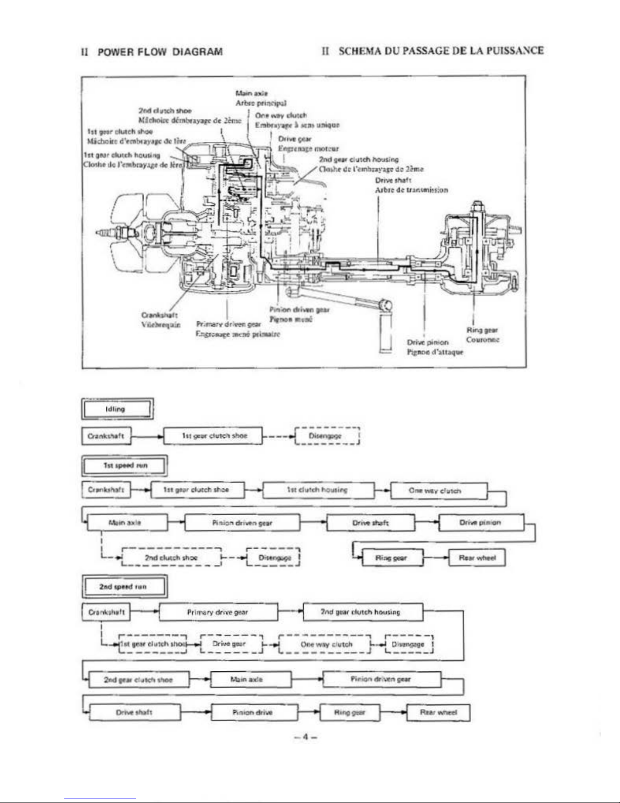
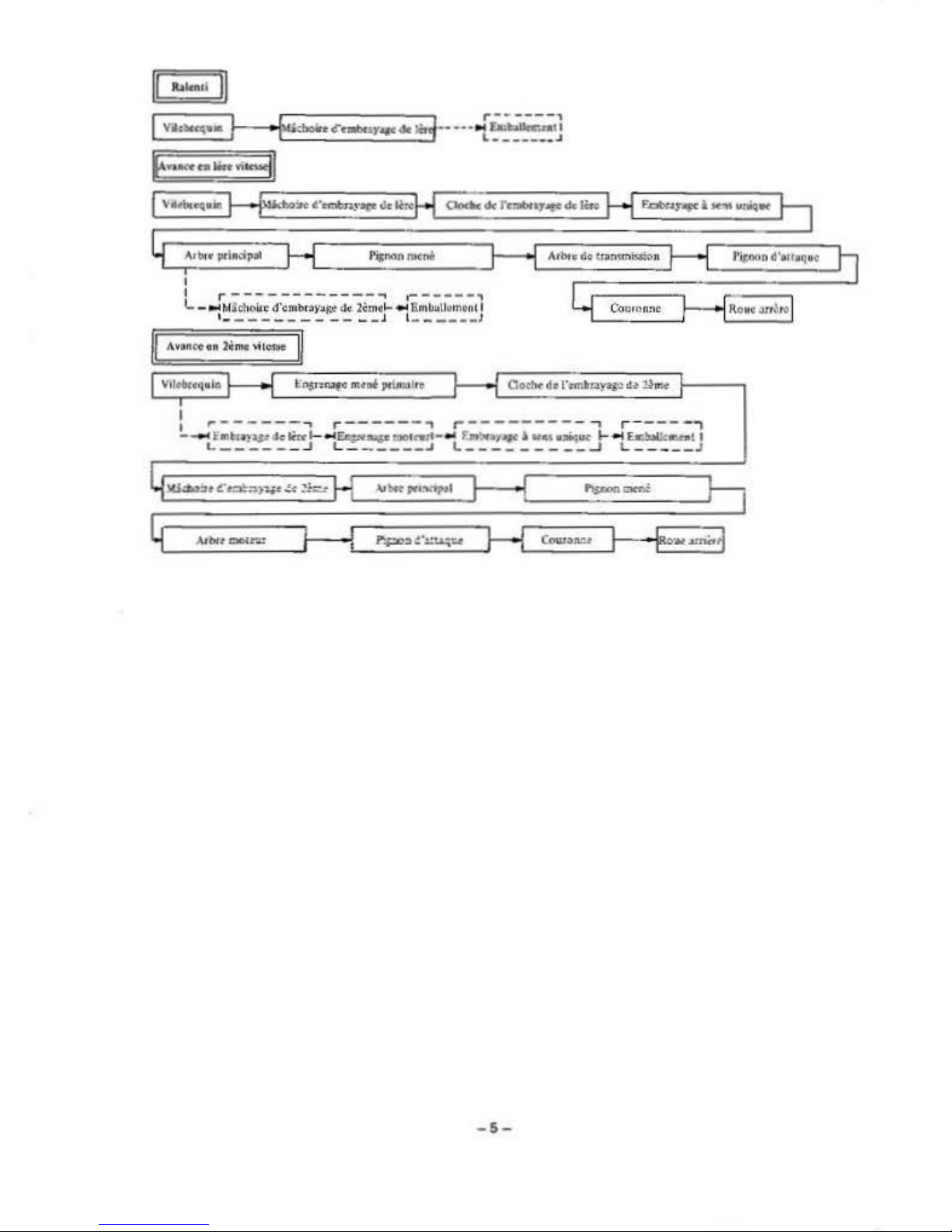
II
POWER FLOW
DIAGRAM
II SCH
EMA
OU
PASSAGE DE
LA
PUISSANCE
I
R.,._
Ori'tllCP.t'llKlltl
Co•nmK
l'ipt>ed'luaqw
l
dlit"19
r:::::::7.l
-
~
---{-;;;;.;,;--
;
~
--------J
hi
dutdt
hOlatflf
I
L.r--~:.:;:;:---i_
_
_:-
-.;:.;;:;1
L.----------
-'
L-
----~
11
.........
. .
O•n'-:ttifll
I
I
r-------
.,
r--
---
- ,
r--------
--...,
r
-----
,
L--t'~'~'~1~1~h~~
~-t-~~~~
_.f
.._,L __
~-w-"':~~-
-J-t_
~~·-
J
G]
I
Yl"'6'C'«l
..
•
L_____iV:
d)oftCC"abar••OLJ._H
..
.,f
~.;..;;;t1
.
~
~
L·--·--·J
E··-
..
""
~
""31
I
I
... --------
----
-.
.-
-----,
L -•Mfcholtc
(l'entbr:sy:.i~
d.:.
lCmc~..,.
6mltat
hlm111t
I
'-
----
- - -
--
__
J 1------'
I r
--
----
.,
r--
----
....
,..--------
-,
r----
-.,
L
_..E•~u.tdc~
._.
..,.
£A:::otm;.•:no4t'Wtl-
.,.
f'ai
':lf
•1,.,,c'
v'"
•*w
~
-tE.:
~e...ot
1
L-----
- J
L-
-----J
L---------~
L
---
--
J
-5-
JJ1
REAR ARM
ANO
REAR
SUSPENS
ION
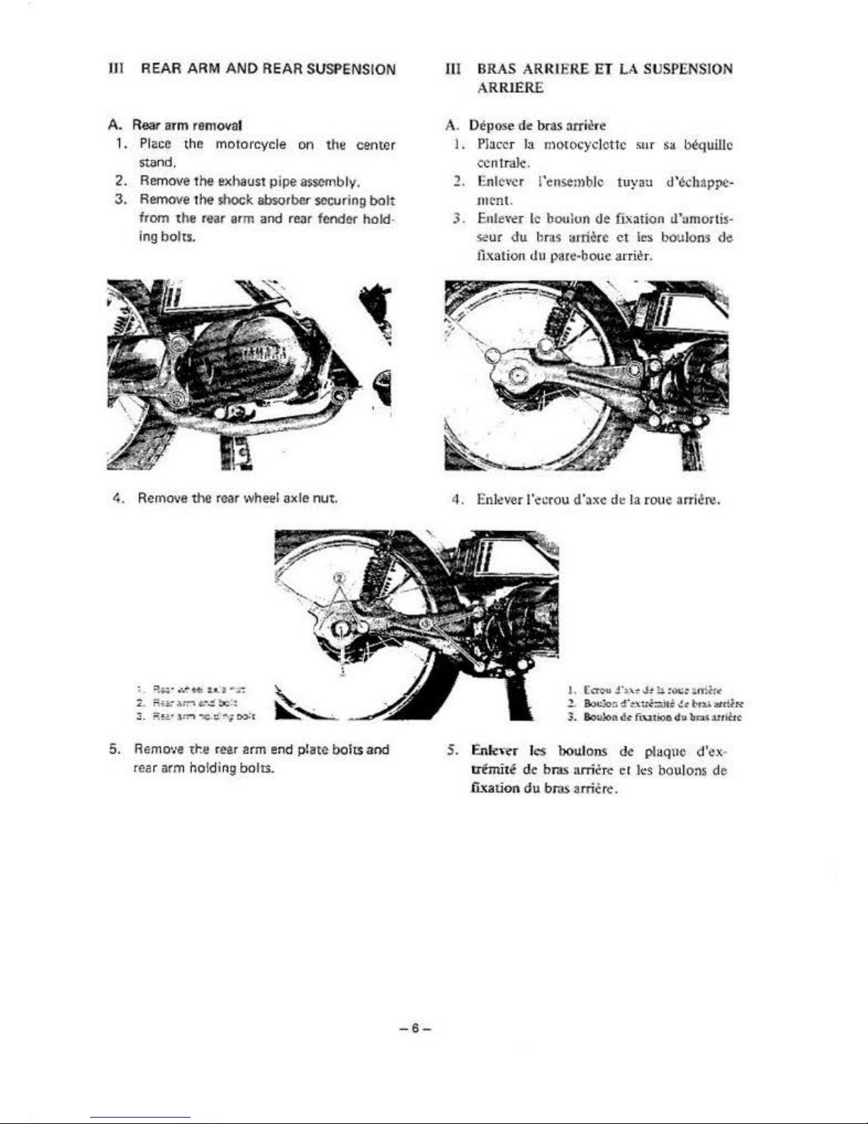
A.
Rear
arm
removal
1. Place the motorcycle
on
the center
stand.
2.
Remove the exhaust pipe assembly.
3.
Remo
ve
the
shock
absorber
securing
bolt
from t
he
rear arm and rear
fcndet
hold·
ing bolts.
4. Remove the r
ear
wheel axle
nut
.
~. M::
•IT"
~.=x::
3.
R!.a•
.lf':"'l
"C.C.";o->="t
5.
Remo•Je
the
rear arm end pl
ate
bolts
and
rear arm hold i
ng
bolts.
-6-
III BRAS ARRI ERE EI LA SUSPENSION
ARRlERE
A. Depose
de
bras
:irriCre
l.
Placer la motocyclotlc sur
sa
bl!quillc
ccntraJe
.
2. Enlc,-cr i'ense:nblc
tuyau
tl'~cbappe·
mcnt
.
3.
Enle\"<r
le boulun
de
fi.,ation tl'amortis-
se
ur
du
hr-.s
onierc
ct
les boulons
de
fixation
<lu
pare-boue
arrit!r.
4.
Enl~ver
l'ecrou d'axc
de
la roue
ani~re.
1.
[;.TeU
J·:~.:'"' J~
u
:Ot.i:
imh<
.l~!i~·:_,t;,C::..icil!'C't-n.l.Wrilti'
3-.
BoWo
nd-tfL'
utiondi;ib
r.a:.,:utlUc
5.
Enkwr
ks
boulons
de
plaque
d'ex
·
t:rimite
de
bras arricrc
ct
ks
boulons de
fi.~ation
du
bros arric
r¢
.
 Loading...