


Yamaha
FZR400
Service
Manual
1988-1989 Models

CONTENTS
CHAPTER 1.
GENERAL INFORMATION
MOTORCYCLE IDENTIFICATION
................................
l-l
VEHICLE IDENTIFICATION NUMBER
.........................
l-l
ENGINE SERIAL NUMBER
................................... l-l
IMPORTANT INFORMATION.
..........................
.......
l-2
PREPARATION FOR REMOVAL
.....................
....... l-2
ALL REPLACEMENT PARTS
........................ ....... l-2
GASKETS, OIL SEALS, AND O-RINGS
................ .......
l-2
LOCK WASHERS/PLATES AND COTTER PINS
......... ....... l-3
BEARINGS AND OIL SEALS
........................
....... l-3
CIRCLIPS
........................................
....... l-3
SPECIAL TOOLS.
.............................................
l-4
FOR TUNE UP
.............................................
1-4
FOR ENGINE SERVICE
.....................................
l-5
FOR CHASSIS SERVICE
.....................................
1-B
FOR ELECTRICAL COMPONENTS
............................
l-9
CHAPTER 2.
SPECIFICATIONS
SPECIFICATIONS
.............................................
2-l
GENERAL SPECIFICATIONS
................................. 2-l
MAINTENANCE SPECIFICATIONS
............................
2-4
ENGINE................................................2-
4
CHASSIS...............................................2-11
ELECTRICAL
..........................................
.2-14
GENERAL TORQUE SPECIFICATIONS.
.......................
.2-16
DEFINITION OF UNITS
.....................................
2-16
LUBRICATION POINT AND GRADE OF LUBRICANT
.............
2-17
LUBRICATION DIAGRAM. . . . , . . . . . . . . . . . . . . . . . . . . . . . . . . . . . . . . . 2-19
. . . . . . . . . . . . . . . . . . . . . . . . . .
2-20
COOLANT DIAGRAM
................
CABLE ROUTING
.................................
. . . . . . . . . . . .
2-21
CHAPTER 3.
PERIODIC INSPECTION AND ADJUSTMENT
INTRODUCTION. . . . . . . . . . . . . . . . . . . . . . . . . . . . . . . . . . . . . . . . . . . . . . ,
3-1
MAINTENANCE INTERVALS CHART
.............................
.3-l
PERIODIC MAINTENANCE EMISSION CONTROL SYSTEM
........
.3-l
GENERAL MAINTENANCE/LUBRICATION
..................... .3-2
COWLING REMOVAL AND INSTALLATION . . . . . . . . . . . . . . . . . . . . . . .
.3-4
ENGINE .....................................................
3-7
EXUP CABLE ADJUSTMENT (For California only)
................
3-7
VALVE CLEARANCE ADJUSTMENT
..........................
3-8
CARBURETOR SYNCHRONIZATION
.......................... 3-15
IDLE SPEED ADJUSTMENT
..................................
3-17
THROTTLE CABLE FREE PLAY ADJUSTMENT
.................
3-18
SPARK PLUG INSPECTION
..................................
3-19
IGNITION TIMING CHECK
...................................
3-20
COMPRESSION PRESSURE MEASUREMENT
....................
3-21
ENGINE OIL LEVEL INSPECTION
.............................
3-23
ENGINE OIL REPLACEMENT
................................ 3-23
ENGINE OIL FILTER REPLACEMENT
......................... 3-24
CLUTCH ADJUSTMENT.
.................................... 3-26
AIR FILTER CLEANING
.....................................
3-27
CARBURETOR JOINT INSPECTION
...........................
3-27
FUEL LINE INSPECTION
....................................
3-27
CRANKCASE VENTILATION HOSE INSPECTION ................
3-28
EXHAUST SYSTEM INSPECTION
.............................
3-28
COOLANT LEVEL INSPECTION
..............................
3-29
COOLANT REPLACEMENT
..................................
3-29
CHASSIS
......
.
..............................................
3-32
FRONT BRAKE ADJUSTMENT
...............................
3-32
REAR BRAKE ADJUSTMENT
................................
3-32
BRAKE FLUID INSPECTION
................................. 3-33
BRAKE PAD INSPECTION
................................... 3-33
REAR BRAKE LIGHT SWITCH ADJUSTMENT. .................. 3-33
BRAKE HOSE INSPECTION
.................................. 3-34
AIR
BLEEDlNG............................................3-3
4
DRIVE CHAIN SLACK ADJUSTMENT
.......................... 3-35
DRIVE CHAIN LUBRICATION
................................
3-37
STEERING HEAD INSPECTION
...............................
3-37
FRONT FORK INSPECTION
..................................
3-40
REAR SHOCK ABSORBER ADJUSTMENT
...................... 3-40
TIRE INSPECTION
.........................................
3-41
WHEEL INSPECTION
.......................................
3-42
CABLE INSPECTION
........................................ 3-43
LUBRICATION
............................................ 3-43
ELECTRICAL.
................................................
3-44
BATTERY INSPECTION
.....................................
3-44
FUSE INSPECTION
.........................................
3-46
HEADLIGHT BEAM ADJUSTMENT
............................
3-46
HEADLIGHT BULB REPLACEMENT
...........................
3-47
TAIL/BRAKE BULB REPLACEMENT
..........................
3-48
CHAPTER 4.
ENGINE OVERHAUL
ENGINE REMOVAL
...........................................
.4-l
LOWER COWLING, CENTER COWLING,
UPPER COWLING AND TOP COVER.
.........................
.4-l
FUEL TANK
...............................................
.4-l
ENGINEOIL..
.................................
..~.........4-
1
COOLANT.................................................4-
1
AIR FILTER CASE AND CARBURETOR.,
......................
.4-l
RADIATOR................................................4-
2
MUFFLER ASSEMBLY
......................................
.4-2
CLUTCH CABLE AND DRIVE CHAIN
..........................
.4-4
LEADS....................................................4-
4
ENGINE REMOVAL
........................................
.4-5
ENGINE DISASSEMBLY
........................................
.4-7
CYLINDER HEAD COVER, CAMSHAFT AND
CYLINDER HEAD
.........................................
.4-7
CYLINDER AND PISTON
...................................
.4-10
STARTER CLUTCH
........................................
.4-12
CLUTCH..................................................4-13
A.C. MAGNETO
...........................................
.4-14
WATER PUMP
............................................
.4-15
OIL PUMP AND SHIFT SHAFT
...............................
.4-16
OIL PAN AND OIL STRAINER.
..............................
.4-17
STARTER MOTOR
.........................................
4-18
CRANKCASE DISASSEMBLY
.................................
4-18
TRANSMISSION, SHIFTER AND SHIFT CAM.
...................
4-19
CRANKSHAFT
.............................................
4-20
VALVE PAD AND VALVE
...................................
4-21
CONNECTING ROD
.........................................
4-23
INNER ROTOR (OIL PUMP).
.................................
4-23
INSPECTION AND REPAIR
.....................................
4-24
CYLINDER HEAD
.............................
,
............
4-24
VALVE...................................................4-2
5
VALVE GUIDE
I:.
.................................
.4-26........
VALVE SEAT.
............................................
.4-27
VALVE SPRING
...........................................
.4-30
VALVE LIFTER
...........................................
.4-31
CAMSHAFT, CAM CHAIN AND CAM SPROCKET
................
.4-31
CYLINDER AND PISTON
...................................
.4-33
PISTON RING AND PISTON PIN
.............................. 4-35
CRANKSHAFT AND CONNECTING ROD
.......................
4-37
OlLPUMP.................................................4-4
1
PRlMARYDRlVE..........................................4-4
2
STARTER CLUTCH
........................................
.4-43
CLUTCH..................................................4-4
4
TRANSMISSION
.......................................... .4-46
RELIEF VALVE AND PIPE
..................................
.4-47
CRANKCASE
............................................. .4-47
BEARING AND OIL SEAL
..................................
.4-47
YAMAHA EXHAUST VARIABLE VALVE (For California only)
..... .4-48
ENGINE ASSEMBLY AND ADJUSTMENT.
........................
.4-49
INNER ROTOR (OIL PUMP).
................................ .4-49
CONNECTING ROD.
.......................................
.4-49
CRANKSHAFT
............................................
.4-50
VALVE PAD AND VALVE
.................................. .4-51
CRANKCASE
.............................................
.4-54
TRANSMISSION
..........................................
.4-55
TRANSMISSION, SHIFTER AND SHIFT CAM
................... .4-56
CRANKCASE ASSEMBLY
................................... .4-57
STARTER MOTOR
........................................ .4-59
OIL PAN AND OILSTRAINER
............................... .4-59
OIL PUMP AND SHIFT SHAFT.
.............................. .4-60
A.C. MAGNETO
........................................... .4-61
CLUTCH..................................................4-6
3
STARTER CLUTCH
........................................
.4-65
PISTON AND CYLINDER
...................................
.4-67
CYLINDER HEAD AND CAMSHAFT
.......................... .4-70
CAM CHAIN TENSIONER
................................... .4-75
REMOUNTING ENGINE
.................................... .4-76
YAMAHA EXHAUST VARIABLE VALVE (For California only)
......4-78
CHAPTER 5.
COOLING SYSTEM
RADlATOR...................................................5-
1
REMOVAL.................................................5-
2
INSPECTION...............................................5-
3
INSTALLATION
...........................................
.5-4
WATER PUMP AND THERMOSTATIC VALVE.
......................
5-6
REMOVAL.................................................5-
7
lNSPECTlON...............................................5-
9
INSTALLATION
..........................................
.5-10
CHAPTER 6.
CARBURETOR
CARBURETOR
...............................................
6-l
SECTIONVIEW
............................................
6-2
REMOVAL ................................................
6-3
DISASSEMBLY
............................................
6-5
INSPECTION ..............................................
6-6
ASSEMBLY.. .............................................
6-B
INSTALLATION
...........................................
6-9
,:
i;
ADJUSTMENT
.............................................
6-10
CHAPTER 7.
CHASSIS
FRONT WHEEL.
..............................................
7-l
REMOVAL
................................................
7-2
INSPECTION ..............................................
7-2
INSTALLATION
...........................................
7-4
REAR WHEEL
................................................
7-7
REMOVAL ................................................
7-B
INSPECTION
..............................................
7-B
INSTALLATION
...........................................
7-9
FRONT AND REAR BRAKE.
................................... .7-10
BRAKE PAD REPLACEMENT
................................
.7-12
CALIPER DISASSEMBLY
...................................
.7-16
MASTER CYLINDER DISASSEMBLY
......................... .7-18
INSPECTION AND REPAIR
.................................
.7-19
ASSEMBLY ...............................................
7-21
FRONT FORK ...............................................
.7-28
REMOVAL................................................7-2
9
DISASSEMBLY ............................................ 7-30
lNSPECTlON..............................................7-3
1
ASSEMBLY
............................................... 7-32
INSTALLATION ...........................................
7-34
STEERING HEAD AND HANDLEBAR.
.............................
7-36
REMOVAL................................................7-3
8
lNSPECTlON..............................................7-4
1
INSTALLATION ........................................... 7-42
REAR SHOCK ABSORBER AND
SWINGARM
.......................
7-47
HANDLING NOTES
.........................................
7-49
DISPOSAL NOTES.
.........................................
7-49
REMOVAL................................................7-4
9
lNSPECTlON..............................................7-5
2
INSTALLATION ........................................... 7-54
DRIVE CHAIN AND SPROCKET
.................................
7-56
REMOVAL................................................7-5
6
INSPECTION AND CLEANING
................................
7-56
INSTALL’ATION
...........................................
7-57
CHAPTER 8.
ELECTRICAL
FZR400U/SUC
CIRCUIT DIAGRAM
. . . . . . . . . . . . . . . . . . . . . . . . . . . .
8-1
ELECTRICAL COMPONENTS.. . . . . . . . . . . . . . . . . . . . . . . . . . . . . . . . . . .
8-3
CHECKING OF SWITCHES.
..................................... .8-5
SWITCH CONNECTION AS SHOWN IN MANUAL
.................
.8-5
CHECKING SWITCH FOR TERMINAL CONNECTION
............. .8-5
CHECKING OF BULBS
.........................................
.8-8
KINDS OF BULBS
.......................................... .8-8
CHECKING BULB CONDITION
...............................
.8-8
IGNITION SYSTEM.
...........................................
8-l
1
Cl RCUIT DIAGRAM
........................................
8-11
DIGITAL IGNITION CONTROL SYSTEM DESCRIPTION
........... 8-13
OPERATION
............................................
..8-13
TROUBLESHOOTING
.......................................
8-14
ELECTRIC STARTING SYSTEM.
.................................
8-21
CIRCUIT DIAGRAM
........................................
8-21
STARTING CIRCUIT OPERATION
............................. 8-23
TROUBLESHOOTING.
...................................... 8-24
STARTER MOTOR
......................................... 8-30
CHARGING SYSTEM.
.......................................... 8-33
CIRCUITDIAGRAM..
....................................
..8-3 3
TROUBLESHOOTING
.......................................
8-35
LIGHTING SYSTEM
...........................................
8-39
CIRCUIT DIAGRAM
........................................ 8-39
TROUBLESHOOTING
.......................................
8-41
LIGHTING SYSTEM CHECK
..................................
8-44
SIGNALSYSTEM ..............................................
8-49
CIRCUIT DIAGRAM
........................................
8-49
TROUBLESHOOTING
.......................................
8-51
SIGNAL SYSTEM CHECK.
...................................
8-53
COOLING SYSTEM.
........................................... 8-69
Cl
RCUIT
DIAGRAM
........................................
8-69
TROUBLESHOOTING
.......................................
8-71
FUELSYSTEM................................................8.7
5
CIRCUIT DIAGRAM
.......................................
.8-75
FUEL PUMP CIRCUIT OPERATION
............................
8.77
TROUBLESHOOTING
.......................................
8-78
FUEL PUMP TEST.
........................................
.8-82
YAMAHA EXHAUST VARIABLE VALVE SYSTEM
(For California only).
......................................... .8-83
CIRCUIT DIAGRAM ....................................... .8-83
TROUBLESHOOTING ......................................
.8-85
METER ASSEMBLY
...........................................
.8-89
REMOVAL................................................8-9
0
INSTALLATION ...........................................
8-91
CHAPTER 9.
TROUBLESHOOTING
STARTING FAILURE/HARD STARTING. . . . . . . . . . . . . . . . . . . . . . . . . . . 9-l
POOR IDLE SPEED PERFORMANCE . . . . . . . . . . . . . . . . . . . . . . . . . . . . . . 9-3
POOR MEDIUM AND HIGH SPEED PERFORMANCE.. . . . . . . . . . . . . . . . . 9-4
FAULTY GEAR SHIFTING.. . . . . . . . . . . . . . . . . . . . . . . . . . . . . . . . . . . . . . 9-4
CLUTCH SLIPPING/DRAGGING . . . . . . . . . . . . . . . . . . . . . . . . . . . . . . . . . . 9-5
OVERHEATING OR OVER-COOLING.. . . . . . . . . .
I..
. . . . . . . . . . . . . . . . 9-6
FAULTY BRAKE.. . . . . . . . . . . . . . . . . . . . . . . . . . . . . . . . . . . . . . . . . _ . . . . 9-7
FRONT FORK OIL LEAKAGE/MALFUNCTION.. . . . . . . . . . . . . . . . . . . . . 9-7
INSTABLE HANDLING.. . . . . . . . . . . . . . . . . . . . . . . . . . . . . . . . . . . . . . . . . 9-8
FAULTY SIGNALS AND LIGHTS.. . . . . . . . . . . . . . . . . . . . . . . . . . . . . . . . . 9-9
FAULTY EXUP
(For California only) . . . . . . . . . . . . . . . . . . . . . . . . . . . . .
.9-l
0

CONTENTS
GENERAL INFORMATION
.......................................
1
MOTORCYCLE IDENTIFICATION
..............................
1
VEHICLE IDENTIFICATION NUMBER
........................
1
ENGINE SERIAL NUMBER
.................................
1
SPECIFICATIONS ...............................................
2
GENERAL SPECIFICATIONS
..................................
2
MAINTENANCE SPECIFICATIONS
..............................
3
CHASSIS
................................................
3
TIGHTENING TORQUE
....................................
4
GENERAL TORQUE SPECIFICATIONS ..........................
5
PERIODIC INSPECTIONS AND ADJUSTMENTS
......................
6
CHASSIS
...................................................
6
DRIVE
CHAIN SLACK ADJUSTME NT ........................
6
CHASSIS
......................................................
8
REARWHEEL ...............................................
8
REMOVAL ..............................................
9
INSPECTION ............................................
10
INSTALLATION .........................................
10
STATIC WHEEL BALANCE ADJUSTMENT ...................
11
FRONT AND REAR BRAKE
..................................
12
BRAKE PAD REPLACEMENT
..............................
14
CALIPER DISASSEMBLY
..................................
19
MASTER CYLINDER DISASSEMBLY ........................
21
INSPECTION AND REPAIR
................................
23
ASSEMBLY.. ........................................... 26
MOTORCYCLE IDENTIFICATION
GENERAL
INFORMATION
MOTORCYCLE IDENTIFICATION
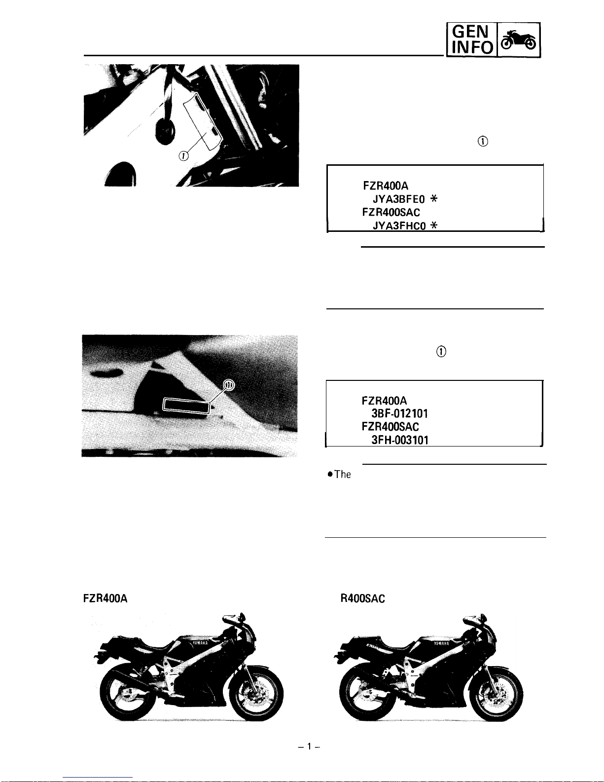
VEHICLE IDENTIFICATION NUMBER
The vehicle identification number @ is stemped
into the right side of the steering head.
Starting serial number:
FZR400A
(Except for California):
JYA3BFEO *
LA012101
FZR400SAC
(For California):
I
JYASFHCO *
LA003101
J
NOTE:
The vehicle identification number is used to
identify your motorcycle and may be used to
register your motorcycle with the licensing
authority in your state.
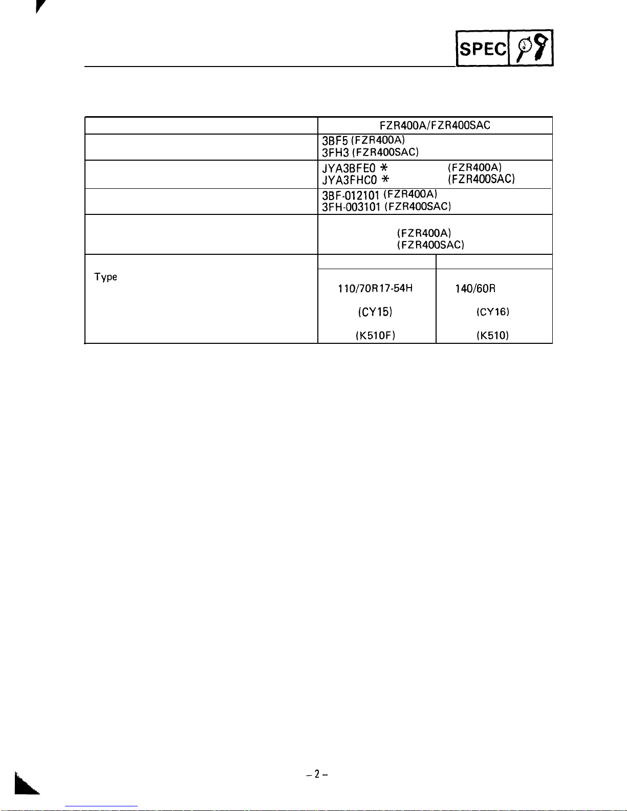
ENGINE SERIAL NUMBER
The engine serial number
@
is stamped into the
right side of the
engine.
Starting serial number:
FZR400A
(Except for California):
3BF-012101
FZR400SAC
(For California):
I
3FH-003101
1
NOTE:
@The
first three digits of these numbers are for
model identifications; the remaining digits are
the unit production number.
@Designs and specifications are subject to
change without notice.
FZRIQOOA
FZ
R400SAC
GENERAL SPECIFICATIONS
JSPECII
SPECIFICATIONS
GENERAL SPECIFICATIONS
Model
Model Code Number:
Vehicle Identification Number:
Engine Starting Number:
Basic Weight:
With Oil and Full Fuel Tank
Tire:
Type
Size
Manufacture (Type)
FZR400A/FZR400SAC
3BF5 (FZR400A)
3FH3 (FZR400SAC)
JYA3BFEO -X
LA012101
(FZR400A)
JYA3FHCO +X-
LA003101
(FZR400SAC)
3BF-012101 (FZR400A)
3FH-003101 (FZR400SAC)
188 kg (414 lb)
(FZR400A)
191 kg (421 lb)
(FZR400SAC)
Front Rear
Tubeless Tubeless
110/70R17-54H 140/60R
1 B-64H
BRIDGESTONE BRIDGESTONE
(CYl5)
(CY16)
DUNLOP DUNLOP
(K5lOF)
(K510)
-2-
MAINTENANCE SPECIFICATIONS
pqq
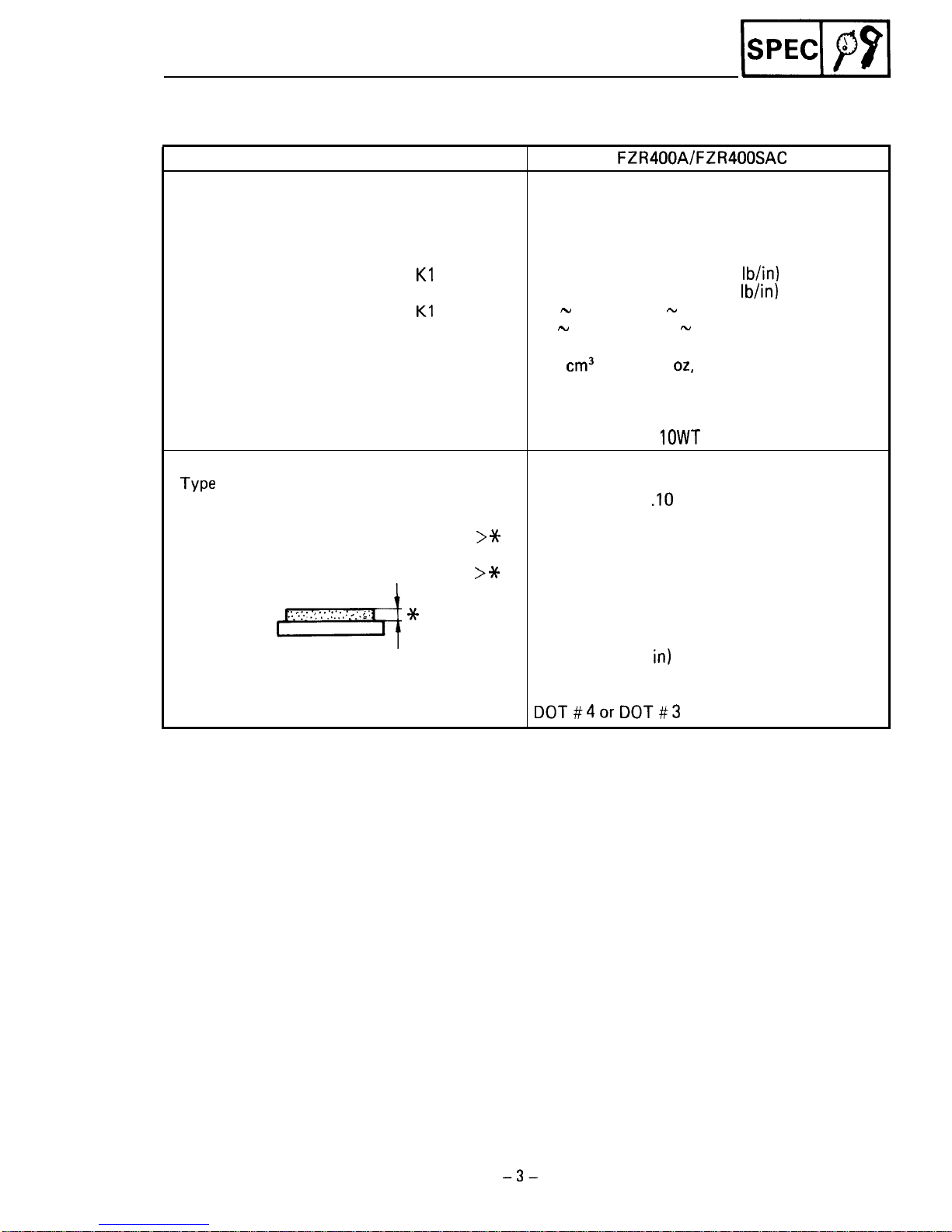
MAINTENANCE SPECIFICATIONS
CHASSIS
Model
FZR400A/FZR400SAC
Front Suspension:
Front Fork Travel
130 mm (5.12 in)
Front Spring Free Length
412 mm (16.2 in)
< Limit > 408 mm (16.1 in)
Collar Length
160 mm (6.3 in)
Spring Rate:
Kl
4.4 N/mm (0.5 kg/mm, 25.2
lb/in)
K2
6.6 N/mm (0.7 kg/mm, 37.5
lb/in)
Stroke
Kl
0.0 - 90 mm (0.0 - 3.54 in)
K2
90 - 130 mm (3.54 - 5.12 in)
Optional Spring No
Oil Capacity
440
cm3
(15.5 Imp
02,
14.9 US oz)
Oil Level (Fully Compression) 92 mm (3.62 in)
Bellow the top of inner fork tube without
fork spring
Oil Grade Yamaha Fork Oil
10WT
or equivalent
Front Disc Brake:
Type
Dual
Disc Outside Diameter x Thickness
282 x 4 mm (11
.lO
x 0.16 in)
Pad Thickness
Inner 5.5 mm (0.22 in)
< Limit
>*
0.5 mm (0.02 in)
Pad Thickness
Outer 5.5 mm (0.22 in)
< Limit
>*
0.5 mm (0.02 in)
4
.: ‘.I.
. .,
‘,‘;:.‘;.
. ;.
.;:
*
Master Cylinder Inside Diameter
15.87 mm (0.62
in)
Caliper Cylinder Inside Diameter
32.10 mm (1.26 in)
Brake Fluid Type
DOT#4or DOT#3
-3-
MAINTENANCE SPECIFICATIONS
-1
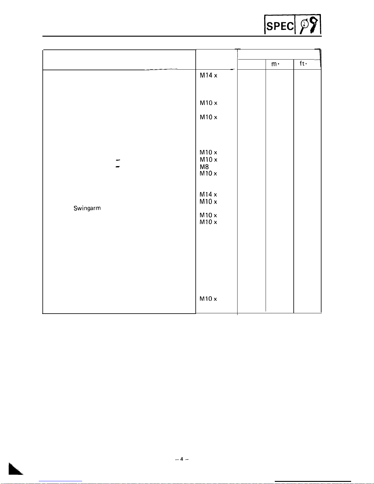
TIGHTENING TORQUE
Part to be tightened
Front Axle and Outer Tube
Rear Axle and Nut
Handlebar Crown and Inner Tube
Handlebar Crown and Steering Stem
Brake Caliper (Front/Rear)
Bleed Screw and Brake Caliper
Brake Hose and Union Bolt
Front Master Cylinder and Master Cylinder Holder
Front Master Cylinder and Cylinder Cap
Front Fender and Outer Tube
Handlebar and Inner Tube
Engine Mounting: Front
Rear - Upper
Rear - Lower
Down Tube and Frame: Front
Rear
Footrest Bracket and Frame
Pivot Axle and Nut
Relay Arm and Frame
Arm and
Swingarm
Arm and Relay Arm
Rear Shock Absorber and Relay Arm
Rear Shock Absorber and Frame
Footrest and Footrest Bracket
Rear Footrest Bracket and Frame
Rear Master Cylinder and Rear Arm Bracket
Cowling and Stay
Compression Bar and Brake Caliper Bracket
Front Fork Pinch Bolt
Sprocket and Clutch Hub
Brake Disc and Clutch Hub
Inner Tube and Steering Stem
Frame and Rear Frame: Upper
Lower
Thread size
-
MI4x
I.5
Ml6 x 1.5
M8 x I.25
M22 x 1.0
MIOx
1.25
M8 x 1.25
MIOx
1.25
M6 x 1.0
M5 x 0.8
M6 x 1.0
M8 x 1.25
MlOx
1.25
MlOx
1.25
M8
x 1.25
MlOx
I.25
M8 x 1.25
Ml0 x 1.25
Ml4x
1.5
MIOx
1.25
Ml0 x 1.25
MlOx
I.25
MIOx
I.25
Ml0 x 1.25
Ml0 x 1.25
M8 x 1.25
M8 x I.25
M6 x 1.0
M8 x I.25
M8 x I.25
M8 x I.25
M8 x 1.25
M8 x I.25
MlOx
1.25
Ml2 x 1.25
-r
Tightening torque
T\
Nm
ma
kg
ft.
lb
58 5.8
42
107
10.7
77
26 2.6
19
110
11.0 80
35 3.5 25
6
0.6 4.3
26 2.6
19
9
0.9 6.5
2
0.2 1.4
6
0.6 4.3
23 2.3
17
55 5.5
40
55 5.5 40
45 4.5 32
60 6.0
43
33 3.3 24
33
3.3
24
90 9.0 65
40
4.0 29
40 4.0
29
40 4.0
29
40 4.0 29
40 4.0 29
57
5.7
41
20
2.0
I4
20 2.0 I4
4
0.4 2.9
23
2.3
17
20 2.0
14
32
3.2 23
20 2.0
14
22
2.2
16
64 6.4 46
88 8.8 64
-4-
GENERAL TORQUE SPECIFICATIONS
Is4
P9l
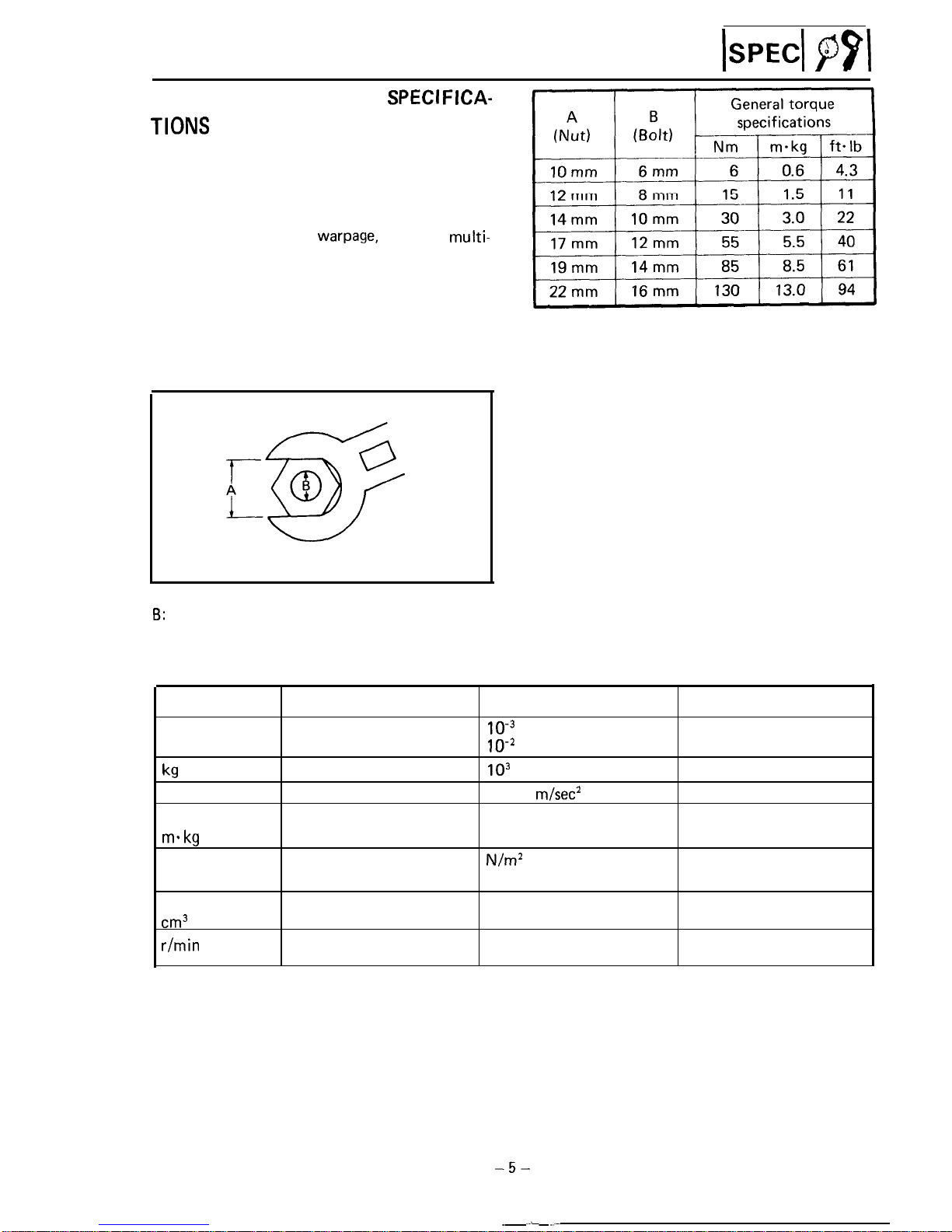
GENERAL
TORQUE
SPECI FICA-
TIONS
This chart specifies torque for standard fasteners
with standard I.S.O. pitch threads. Torque
specifications for special components or assemblies are included in the applicable sections of
this book. To avoid
warpage,
tighten
multi-
fastener assemblies in a crisscross fashion, in
progressive stages, until full torque is reached.
Unless otherwise specified, torque specifications
call for clean, dry threads. Components should
be at room temperature.
A: Distance across flats
6:
Outside thread diameter
DEFINITION OF UNITS
Unit
Read
mm
millimeter
cm
centimeter
kg
kilogram
N
Newton
Nm
Newton meter
mskg
Meter kilogram
Pa Pascal
N/mm Newton per millimeter
L
Liter
cm3
Cubic centimeter
r/min
Revolution per minute
Definition
10e3
meter
IO-*
meter
lo3
gram
1 kg x
m/set*
Nxm
m x kg
N/m2
N/mm
Measure
Length
Length
Weight
Force
Torque
Torque
Pressure
Spring rate
Volume or Capacity
Engine Speed
-5-
DRIVE CHAIN SLACK ADJUSTMENT
PERIODIC INSPECTIONS
AND ADJUSTMENTS
CHASSIS
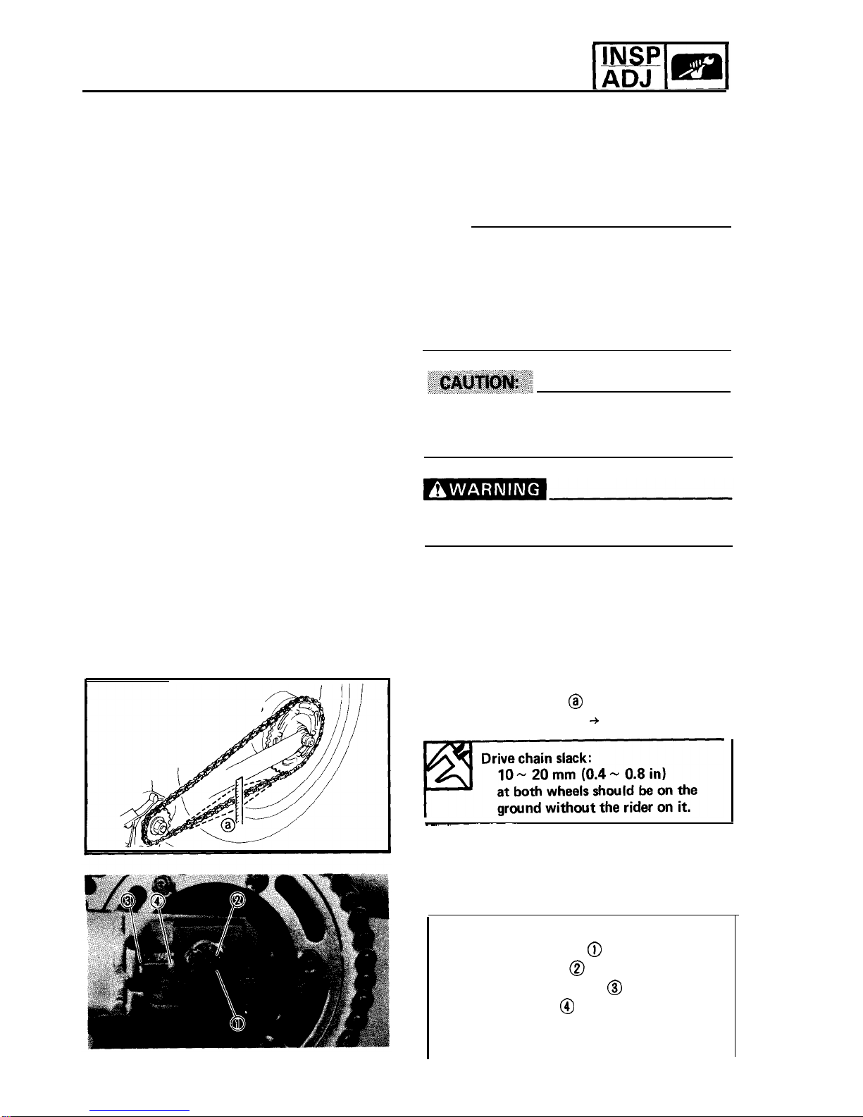
DRIVE CHAIN SLACK ADJUSTMENT
NOTE:
Before checking and/or adjusting the chain slack,
rotate the rear wheel several revolutions. Check
the chain slack several times to find the point
where the chain is the tightest. Check and/or
adjust the chain slack where the rear wheel is in
this “tight chain” position.
Too little of chain slack will overload the engine
and over vital parts; keep the slack within the
specified limits.
Securely support the motorcycle so there is
no danger of it falling over.
1. Place the motorcycle on a level place, and
hold it in an upright position.
2. Check:
??
Drive chain slack
@
Out of specification + Adjust.
>
3. Adjust:
??
Drive chain slack
Adjustment steps:
??
Remove the cotter pin @ .
??
Loosen the axle nut @ .
?? Loosen both locknuts
@
(adjuster) and
turn the adjuster @ clockwise or counter-
clockwise until the specified slack is
obtained.
-6-
.
DRIVE CHAIN SLACK ADJUSTMENT
ADJ m
I1NspI(
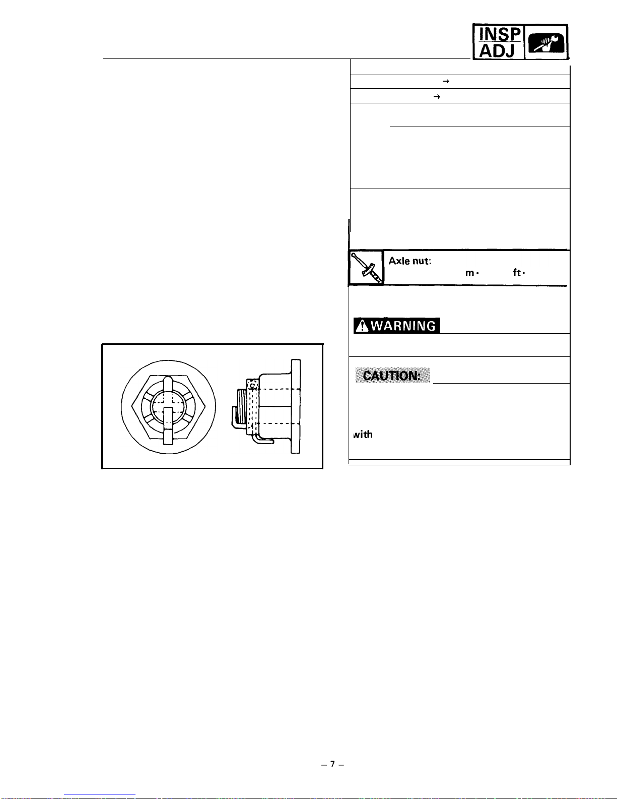
Clockwise
+
Slack is increased.
Counterclockwise
--,
Slack is decreased.
NOTE:
Turn each adjuster exactly the same amount
to maintain correct axle alignment. (There
are
marks on each side of swingarm; use them to
check for proper alignment.)
??
Tighten the locknut.
??
Tighten the axle nut to specification, while
pushing up or down on the chain to zero
slack.
107 Nm (10.7 m- kg, 77
ft.
lb)
??
Install the cotter pin.
Always use a new cotter pin on the axle nut.
Do not loosen the axle nut after torque
tightening. If the axle nut groove is not
aligned with the cotter pin hole, align groove
rnrith
the hole by tightening up on the axle
nut.
-7-
REAR WHEEL
-1
CHASSIS
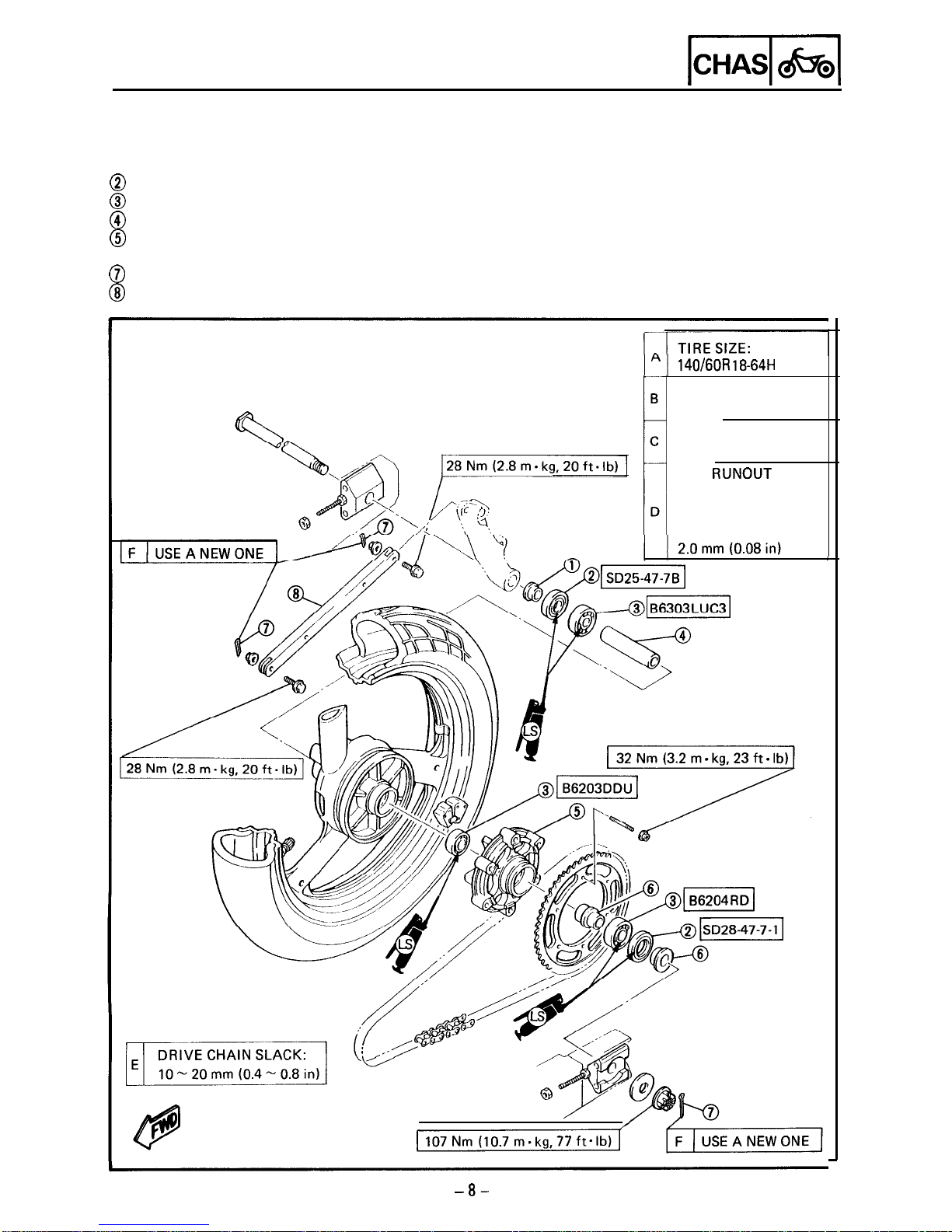
REAR WHEEL
@Collar
@
Oil seal
@
Bearing
@
Spacer
@
Clutch hub
@Collar
@
Cotter pin
@
Tension bar
WEAR LIMIT:
1 .O mm (0.04 in)
140160R 18-64H
RIM SIZE:
MT4.00 x 18
RIM
RUNOUT
LIMIT:
RADIAL:
2.0 mm (0.08 in)
LATERAL:
I
-8-
REAR WHEEL
-1
REMOVAL
1. Place the motorcycle on a level place.
Securely support the motorcycle so there is no
danger of it falling over.
2. Elevate the rear wheel by placing a suitable
stand under the swingarm.
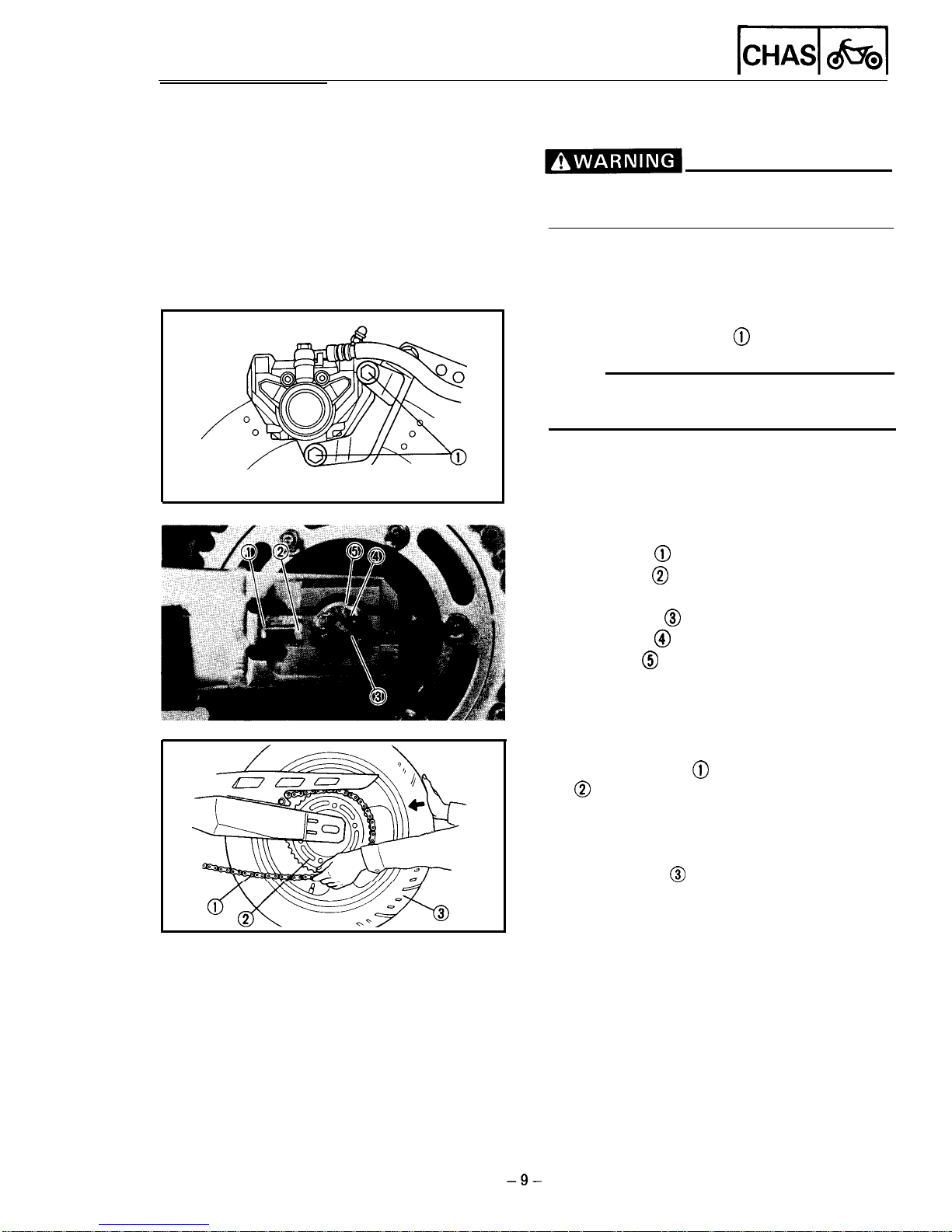
3. Remove:
??
Bolts (brake caliper)
@
NOTE:
Do not depress the brake pedal while the caliper
is removed.
4. Loosen:
??
Locknut
@
??
Adjuster
@
5. Remove:
??
Cotter pin
@I
*Axle nut
@I
??
Washer
@
6. Push the rear wheel forward and disconnect
the drive chain @ from the driven sprocket
0
7. Remove:
??
Rear wheel axle
??
Adjuster collars (left and right)
??
Rear wheel
@
8. Remove:
??
Collar (left and right)
-9-
REAR WHEEL
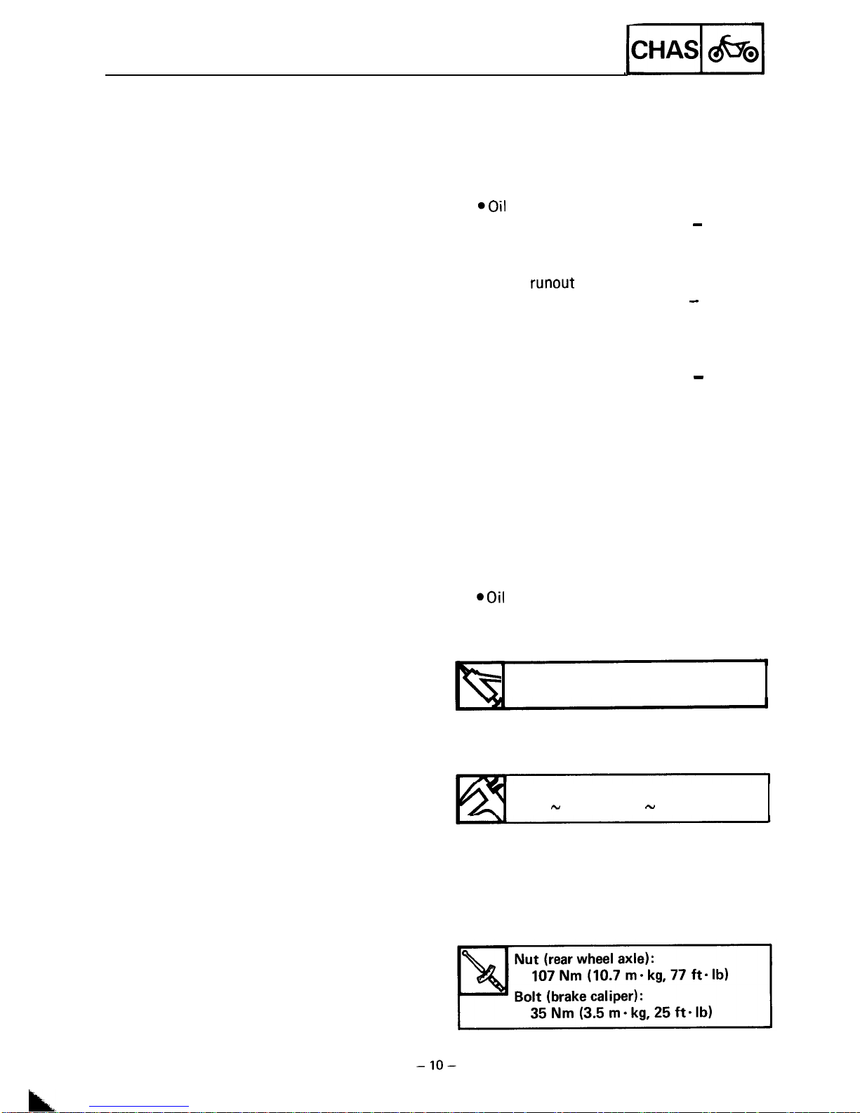
INSPECTION
1. Inspect:
??
Tire
??
Rear wheel axle
??
Wheel
??
Wheel bearings
@Oil seals
Refer to the “FRONT WHEEL - INSPEC-
TION”.
2. Measure:
??
Wheel
runout
Refer to the “FRONT WHEEL - INSPEC- .
TION”.
3. Check:
??
Wheel balance
Refer to the “FRONT WHEEL - INSPEC-
TION”.
INSTALLATION
Reverse the “Removal” procedure.
Note the following points.
1. Lubricate:
??
Rear wheel axle
??
Bearings
*Oil
seals
??
Spacer
??
Collar
Lithium soap base grease
2. Adjust:
??
Drive chain slack
Drive chain slack:
10 - 20 mm (0.4 - 0.8 in)
Refer to the “DRIVE CHAIN SLACK
ADJUSTMENT”.
3. Tighten:
?? Nut (rear wheel axle)
??
Bolts (brake caliper)
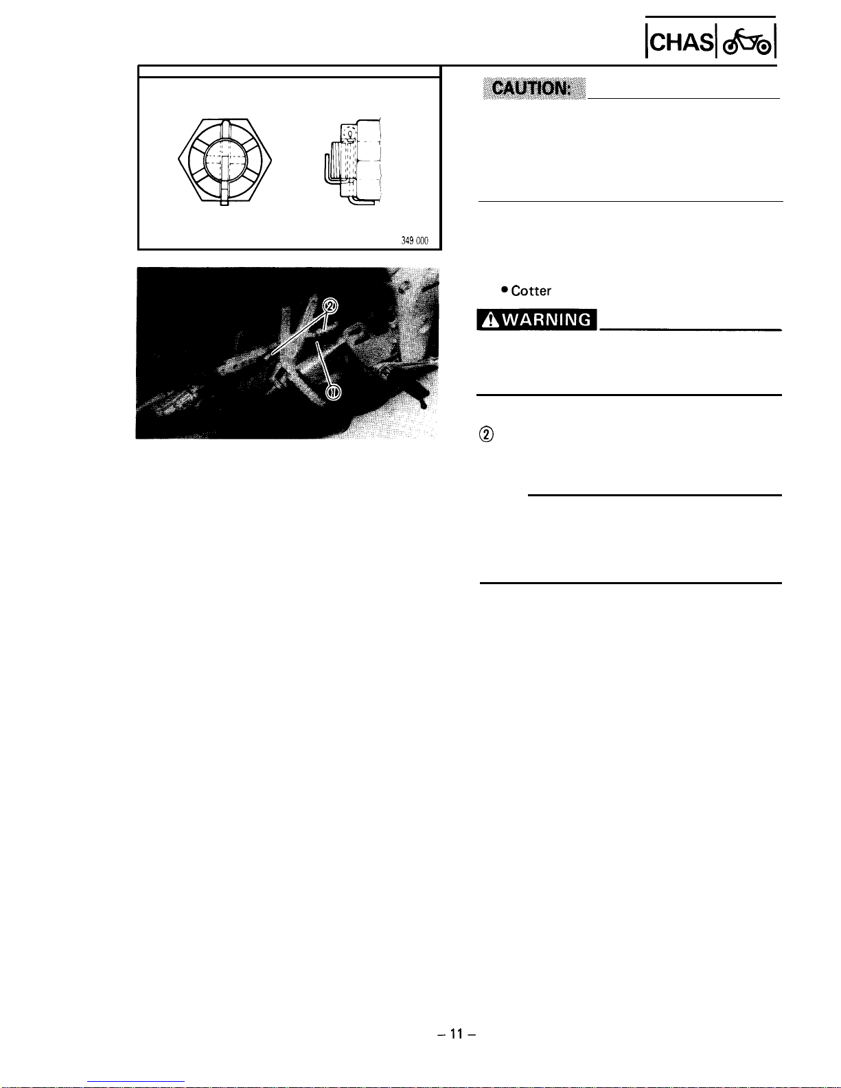
REAR WHEEL
lctf=l
&x31
??
Do not loosen the axle nut after torque tighten-
ing.
??
If the axle nut groove is not aligned with the
wheel shaft cotter pin hole, align groove with
the hole by tightening up on the axle nut.
4. Install:
aCotter
pin
??
Always use a new cotter pin on the axle nut.
??
Make sure that the brake hose is routed prop-
erly.
@Brake hose
@
Brake hose guide
STATIC WHEEL BALANCE ADJUSTMENT
NOTE:
?? After replacing the tire and/or rim, wheel
balance should be adjusted.
?? Adjust the wheel balance with brake disc
and wheel hub installed.
1. Adjust:
??
Wheel balance
Refer to the “FRONT WHEEL -STATIC
WHEEL BALANCE ADJUSTMENT”
section.
-ll-
FRONT AND REAR BRAKE
pqzq
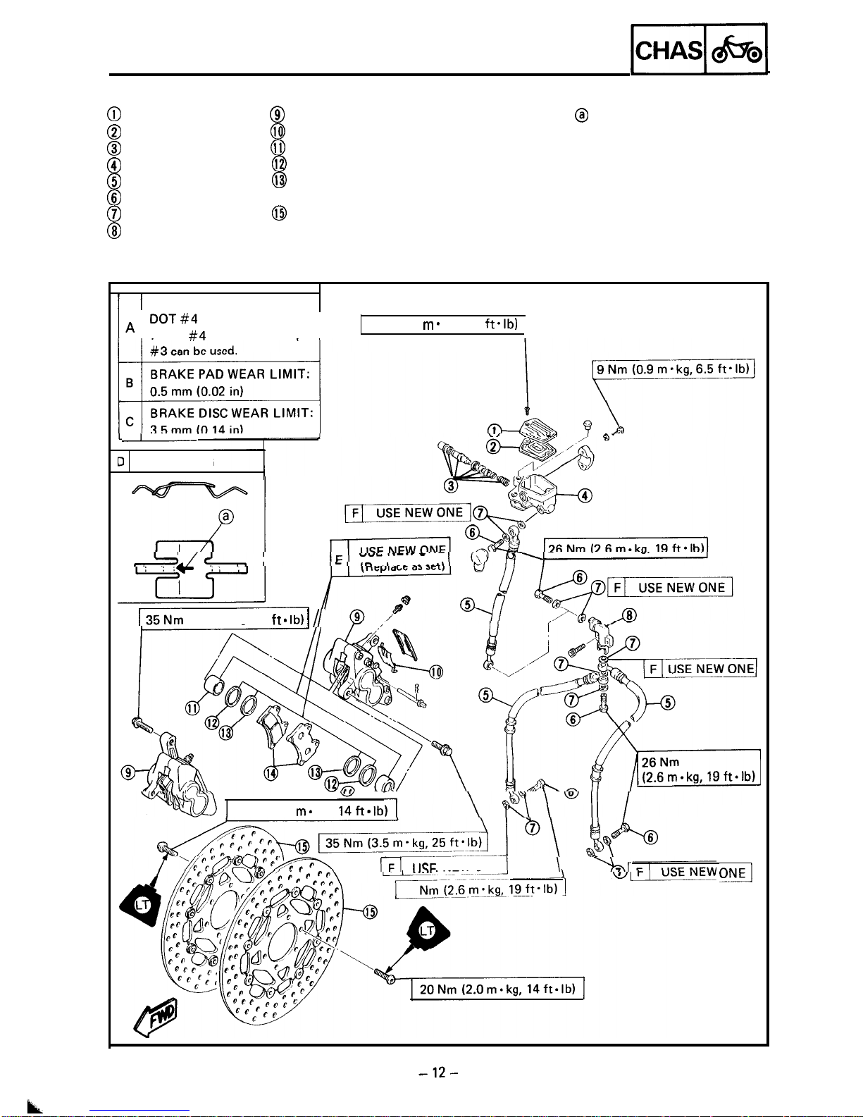
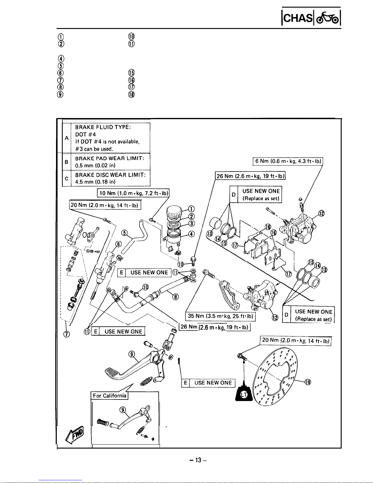
FRONT AND REAR BRAKE
@
Master cylinder cap
@
Brake caliper
@
Diaphragm
@I
Pad spring
@
Master cylinder kit
Q-j?
Piston
@
Master cylinder
@
Piston seal
@
Brake hose
@
Dust seal
@
Union bolt
@Brake pad
@
Copper washer
@
Brake disc
@
Joint
?
The arrow mark @ on the pad spring must pointing
the disc rotating direction.
1 BRAKE FLUID TYPE:
A DOT#4
If DOT #4 is not available,
2 Nm (0.2
rn.
kg, 1.4
ftslb)
I-
1 PAD SPRING
SYL
I
---‘----
-
135
(3.5 m . kg, 25
ft. lb)
1
//
,
20 Nm (2.0 ma kg,
rd
lJSF
NEW ONE 1
\
yr;\r
26
ONA
k
FRONT AND REAR BRAKE
l-s1
@bibi
@
Reservoir tank cap
@
Bush
@Diaphragm
@
Reservoir tank
@
Reservoir hose
@
Master cylinder
@
Master cylinder kit
@
Brake hose
@
Brake pedal
@
Union bolt
0
Copper washer
@Brake caliper
@Piston
@Piston seal
@
Dust seal
@I
Brake pad
@
Pad shim
@I
Pad spring
@Brake disc
>/26Nm
(2.6m=kg, 19ft*Ib)I
~20NmI2.0m.kn
14ft.lhl)
- 13-
FRONT AND REAR BRAKE
pi$q
Disc brake components rarely require disassem-
bly. DO NOT:
??
Disassembly components unless absolutely nec-
essary.
??
Use solvents on internal brake component.
??
Use contaminated brake fluid for cleaning.
Use only clean brake fluid.
??
AIIOW brake fluid to come in contact with the
eyes otherwise eye injury may occur.
??
Allow brake fluid to contact painted surfaces
or plastic parts otherwise damage may occur.
?? Disconnect any hydraulic connection other-
wise the entire system must be disassembled,
drained, cleaned, and then properly filled and
bled after reassembly.
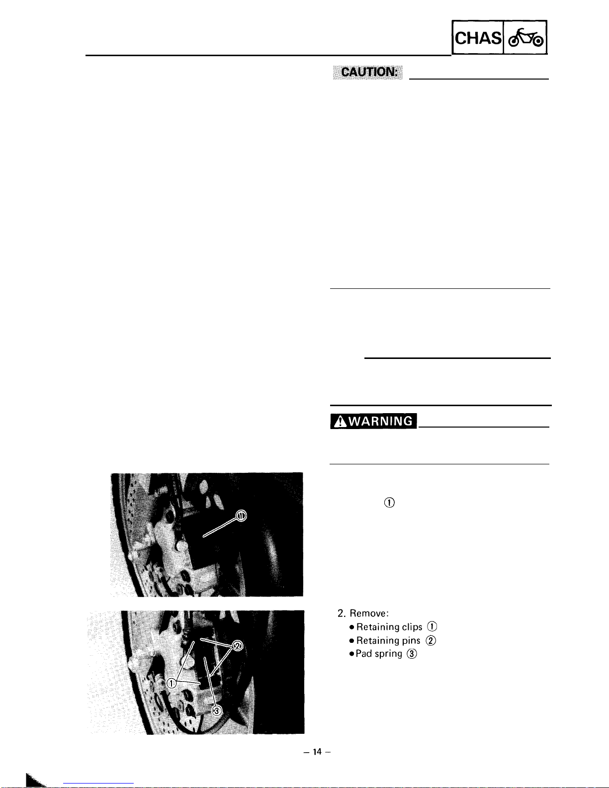
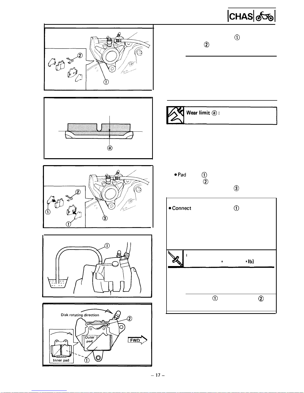
BRAKE PAD REPLACEMENT
NOTE:
It is not necessary to disassemble the brake
caliper and brake hose to replace the brake
pads.
Securely support the motorcycle so there is
no danger of it falling over.
Front brake
1.
Remove:
??
Cover
@
FRONT AND REAR BRAKE
-1
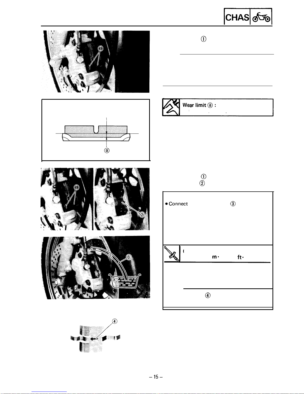
3. Remove:
??
Brake pads
@
NOTE:
?? Replace the pad spring if the pad replacement
is required.
?? Replace the pads as a set if either is found to
be worn to the wear limit.
0.5 mm
(0.02 in)
4. Install:
??
Brake pads
@
??
Pad spring
@
Installation steps:
@Connect
a suitable hose @ tightly to the
caliper bleed screw. Then, place the other
end of this hose into an open container.
?? Loosen the caliper bleed screw and push the
piston into the caliper by your finger.
*Tighten the caliper bleed screw.
Caliper bleed screw:
6 Nm (0.6 m- kg, 4.3
ft.
lb)
*Install the brake pad (new) and pad spring
(new).
NOTE:
The arrow mark @ on the pad spring must
point in the disc rotating direction.
-15-
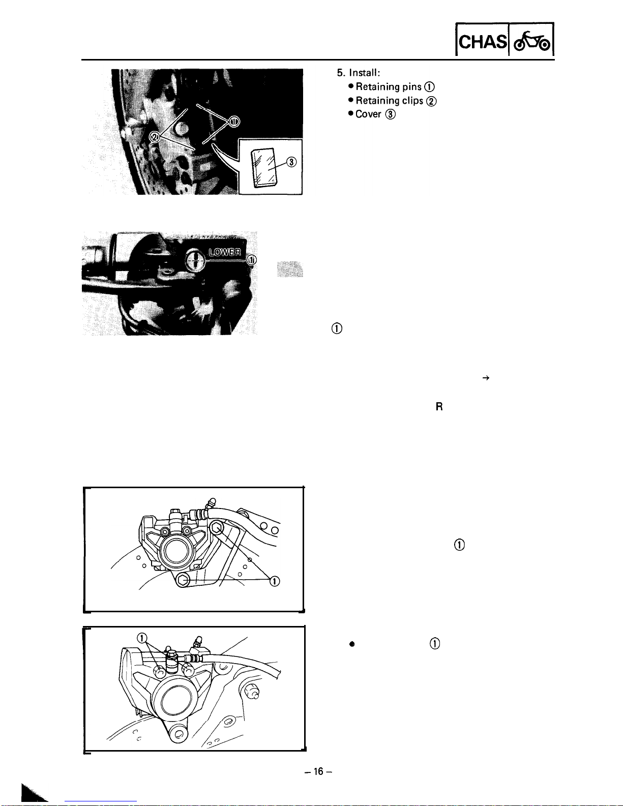
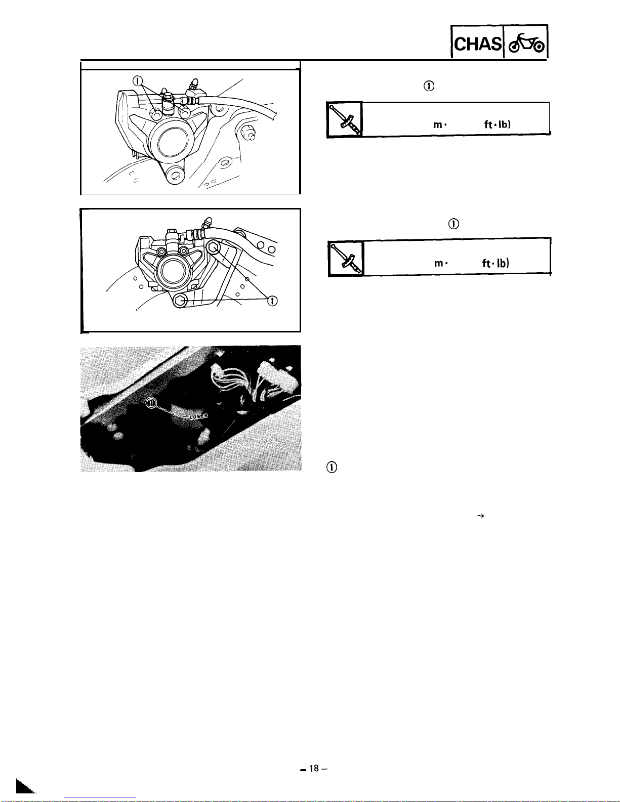
FRONT AND REAR BRAKE
-1
6. Inspect:
?? Brake fluid level
Refer to the “BRAKE FLUID INSPEC-
TION” section in the CHAPTER 3.
@
“LOWER” level line
7.
Check:
?? Brake lever operation
A softy or spongy filling + Bleed brake
system.
Refer to the “Al R BLEEDING” section in
the CHAPTER 3.
3. Remove:
e
Retaining bolts
@
-16-
Rear brake
1. Remove:
??
Seat
2. Remove:
?? Bolts (brake caliper)
@
FRONT AND REAR BRAKE
b-l
&I
4. Remove:
??
Brake pads (with shims)
@
??
Pad spring
@
NOTE :
??
Replace the pad spring if the pad replacement
is required.
??
Replace the pads as a set if either is found to
be worn to the wear limit.
??
Replace the pad shim if the pad replacement is
required.
0.5 mm
(0.02 in)
5. Install:
@Pad
shims
@
??
Pad spring
@
??
Brake pads (with shims)
@
Installation steps:
@Connect
a suitable hose @ tightly to the
caliper bleed screw. Then, place the other
end of this hose into an open container.
??
Loosen the caliper bleed screw and push the
piston into the caliper by your finger.
*Tighten the caliper bleed screw.
Caliper bleed screw:
6 Nm (0.6 m - kg, 4.3 ft -
lb)
@Install the brake pads (new), pad spring
(new) and pad shims (new).
NOTE:
Install pad shims @ and pad spring @ on
caliper as shown in the disc rotating direction.
FRONT AND REAR BRAKE
-1
6. Install:
??
Retaining bolts
@
Retaining bolts:
10 Nm (1.0 ma kg, 7.2
ft. lb)
7. Install:
??
Bolts (brake caliper)
@
Bolts (brake caliper):
35 Nm (3.5
rn-
kg, 25
ft. lb)
8. Inspect:
??
Brake fluid level
Refer to the “BRAKE FLUID INSPEC-
TION” section in the CHAPTER 3.
@
“LOWER” level line
9. Check:
??
Brake pedal operation
A softy or spongy filling + Bleed brake
system.
Refer to the “AIR BLEEDING” section in
the CHAPTER 3.
10. Install:
??
Seat
-
18-
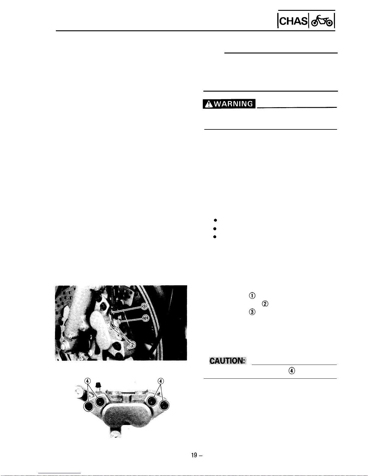
FRONTANDREARBRAKE
ICHASl c&x31
CALIPER DISASSEMBLY
NOTE:
Before disassembling the front or rear brake
master cylinders, drain the brake hose, master
cylinder, brake caliper and reservoir tank of
their brake fluid.
Securely support the motorcycle so there is
no danger of it falling over.
Front brake
1. Remove:
0 Cover
0 Reflector
0 Retaining clips
??
Retaining pins
??
Pad spring
??
Brake pads
Refer to the “BRAKE PAD REPLACE-
MENT” section.
2. Remove:
??
Union bolt
@
??
Copper washers
@
??
Brake hose
@
Place the open hose end into a container
and pump the old fluid out carefully.
3. Remove:
??
Caliper body
Do not loosen the bridge bolts @ .
- 19-
 Loading...