

Yamaha F50F, FT50G, F60C, FT60D, F70A User Manual

OWNER’S MANUAL
Read this manual carefully before operating this
outboard motor.
F40D
F40G
F50F
FT50G
F60C
FT60D
F70A
6C1-28199-79-E0

EMU25052
Read this manual carefully before operating this outboard motor. Keep this
manual onboard in a waterproof bag when boating. This manual should stay
with the outboard motor if it is sold.
Important manual information
WARNING
NOTICE
TIP:
TIP:
EMU25107
To the owner
Thank you for selecting a Yamaha outboard
motor. This Owner’s Manual contains information needed for proper operation, maintenance and care. A thorough understanding
of these simple instructions will help you obtain maximum enjoyment from your new
Yamaha. If you have any question about the
operation or maintenance of your outboard
motor, please consult a Yamaha dealer.
In this Owner’s Manual particularly important
information is distinguished in the following
ways.
: This is the safety alert symbol. It is
used to alert you to potential personal injury
hazards. Obey all safety messages that follow this symbol to avoid possible injury or
death.
EWM00781
A WARNING indicates a hazardous situation which, if not avoided, could result in
death or serious injury.
ECM00701
A NOTICE indicates special precautions
that must be taken to avoid damage to the
outboard motor or other property.
there is any question concerning this manual, please consult your Yamaha dealer.
To ensure long product life, Yamaha recommends that you use the product and perform
the specified periodic inspections and maintenance by correctly following the instructions in the owner’s manual. Any damage
resulting from neglect of these instructions is
not covered by warranty.
Some countries have laws or regulations restricting users from taking the product out of
the country where it was purchased, and it
may be impossible to register the product in
the destination country. Additionally, the warranty may not apply in certain regions. When
planning to take the product to another country, consult the dealer where the product was
purchased for further information.
If the product was purchased used, please
consult your closest dealer for customer reregistration, and to be eligible for the specified services.
The F40DET, F40GET, F50FED, F50FET,
FT50GET, F60CET, FT60DET, F70AET and
the standard accessories are used as a base
for the explanations and illustrations in this
manual. Therefore some items may not apply to every model.
EMU25121
A TIP provides key information to make procedures easier or clearer.
Yamaha continually seeks advancements in
product design and quality. Therefore, while
this manual contains the most current product information available at the time of printing, there may be minor discrepancies
between your machine and this manual. If
F40D, F40G, F50F, FT50G, F60C, FT60D, F70A
OWNER’S MANUAL
©2011 by Yamaha Motor Co., Ltd.
1st Edition, April 2011
All rights reserved.
Any reprinting or unauthorized use
without the written permission of
Yamaha Motor Co., Ltd.
is expressly prohibited.
Printed in Japan

Table of contents
Safety information............................. 1
Outboard motor safety ..................... 1
Propeller............................................ 1
Rotating parts.................................... 1
Hot parts ........................................... 1
Electric shock.................................... 1
Power trim and tilt ............................. 1
Engine shut-off cord (lanyard)........... 1
Gasoline............................................1
Gasoline exposure and spills ............ 2
Carbon monoxide.............................. 2
Modifications ..................................... 2
Boating safety .................................. 2
Alcohol and drugs ............................. 2
Personal flotation devices ................. 2
People in the water ........................... 2
Passengers ....................................... 2
Overloading....................................... 2
Avoid collisions ................................. 3
Weather ............................................ 3
Passenger training ............................ 3
Boating safety publications ............... 3
Laws and regulations ........................ 3
General information .......................... 4
Identification numbers record ...........4
Outboard motor serial number .......... 4
Key number....................................... 4
EC Declaration of Conformity
(DoC) ............................................. 4
CE Marking ..................................... 4
Read manuals and labels................. 6
Warning labels ................................. 6
Specifications and
requirements.................................... 10
Specifications ................................. 10
Installation requirements ................ 13
Boat horsepower rating................... 13
Mounting motor ............................... 13
Yamaha Security System................ 13
Remote control requirements .........13
Battery requirements ......................14
Battery specifications ...................... 14
Mounting battery ............................. 14
Multiple batteries............................. 14
Propeller selection ......................... 14
Start-in-gear protection .................. 15
Engine oil requirements ................. 15
Fuel requirements .......................... 15
Gasoline .......................................... 15
Anti-fouling paint ............................ 16
Motor disposal requirements.......... 16
Emergency equipment ................... 16
Components .................................... 17
Components diagram..................... 17
Fuel tank ......................................... 19
Fuel joint..........................................19
Fuel gauge ...................................... 20
Fuel tank cap...................................20
Air vent screw..................................20
Remote control transmitter ............. 20
Receiver ......................................... 20
Yamaha Security System lock and
unlock mode .................................21
Remote control box ......................... 21
Remote control lever ....................... 21
Neutral interlock trigger ................... 22
Neutral throttle lever........................ 22
Tiller handle .................................... 22
Gear shift lever ............................... 22
Throttle grip .................................... 23
Throttle indicator ............................ 23
Throttle friction adjuster................... 23
Engine shut-off cord (lanyard) and
clip................................................. 24
Engine stop button ......................... 24
Main switch ..................................... 25
Steering friction adjuster ................. 25
Power trim and tilt switch on remote
control or tiller handle.................... 26
Power trim and tilt switch on bottom
cowling ..........................................26
Variable trolling RPM switches........ 27
Trim tab with anode......................... 27
Trim rod (tilt pin).............................. 28
Tilt lock mechanism......................... 28
Tilt support lever for power trim and
tilt or hydro tilt model..................... 28
Cowling lock lever(s) (turn type)...... 29
Flushing device ............................... 29

Table of contents
Fuel filter/Water separator .............. 29
Alert indicator ................................. 30
Instruments and indicators ............ 31
Indicators ....................................... 31
Low oil pressure-alert indicator ....... 31
Overheat-alert indicator .................. 31
Digital tachometer .......................... 31
Tachometer..................................... 32
Trim meter....................................... 32
Hour meter ...................................... 32
Low oil pressure-alert indicator ....... 32
Overheat-alert indicator .................. 33
Digital speedometer ....................... 33
Speedometer .................................. 33
Fuel gauge ...................................... 33
Trip meter / Clock / Voltmeter ......... 34
Fuel level-alert indicator.................. 35
Low battery voltage-alert
indicator ........................................ 35
Analog tachometer ......................... 35
Low oil pressure-alert indicator ....... 35
Overheat-alert indicator .................. 36
Analog trim meter ........................... 36
6Y8 Multifunction meters................ 36
6Y8 Multifunction tachometers....... 36
Start-up checks ............................... 37
Yamaha Security System
information ...................................38
Adjusting trolling speed ................... 38
Low oil pressure-alert...................... 39
Overheat alert ................................. 39
Water separator alert ...................... 40
Engine trouble alert......................... 40
Low battery voltage-alert................. 41
6Y8 Multifunction speed & fuel
meters .......................................... 41
6Y8 Multifunction speedometers.... 42
6Y8 Multifunction fuel
management meters .................... 43
Engine control system.................... 44
Alert system ................................... 44
Overheat alert ................................. 44
Low oil pressure alert...................... 45
Installation ....................................... 46
Installation ...................................... 46
Mounting the outboard motor ..........46
Operation ......................................... 48
First-time operation ........................ 48
Fill engine oil ................................... 48
Breaking in engine .......................... 48
Getting to know your boat ...............48
Checks before starting engine ....... 48
Fuel level......................................... 48
Remove the top cowling.................. 49
Fuel system..................................... 49
Controls........................................... 49
Engine shut-off cord (lanyard) ......... 50
Engine oil ........................................ 50
Engine .............................................51
Flushing device ............................... 51
Install top cowling............................51
Power trim and tilt system ............... 52
Battery............................................. 52
Filling fuel ...................................... 53
Operating engine ........................... 54
Sending fuel (portable tank) ............54
Starting engine ................................ 55
Checks after starting engine .......... 58
Cooling water .................................. 58
Warming up engine........................ 58
Manual start and electric start
models .......................................... 58
Checks after engine warm up ........ 59
Shifting ............................................ 59
Stop switches .................................. 59
Shifting ........................................... 59
Stopping boat................................. 60
Trolling ........................................... 61
Adjusting trolling speed ................... 61
Stopping engine ............................. 61
Procedure........................................61
Trimming outboard motor............... 62
Adjusting trim angle (Power trim
and tilt) .......................................... 63
Adjusting trim angle for hydro tilt
models .......................................... 64
Adjusting boat trim ..........................64
Tilting up and down........................ 65
Procedure for tilting up (hydro tilt
models) ......................................... 65

Table of contents
Procedure for tilting up (power trim
and tilt models) ............................. 66
Procedure for tilting down (hydro
tilt models) .................................... 67
Procedure for tilting down (power
trim and tilt models) ...................... 68
Shallow water ................................ 69
Hydro tilt models ............................. 69
Power trim and tilt models............... 70
Cruising in other conditions ............71
Maintenance..................................... 72
Transporting and storing outboard
motor ............................................ 72
Storing outboard motor ................... 72
Procedure ....................................... 73
Lubrication ...................................... 74
Flushing power unit......................... 75
Cleaning the outboard motor ......... 76
Checking painted surface of
outboard motor ............................. 76
Periodic maintenance..................... 76
Replacement parts.......................... 77
Severe operating conditions ........... 77
Maintenance chart 1 ....................... 78
Maintenance chart 2 ....................... 80
Greasing ......................................... 81
Cleaning and adjusting spark
plug ............................................... 82
Inspecting idle speed ...................... 83
Changing engine oil ........................ 84
Inspecting wiring and connectors.... 85
Checking propeller .......................... 86
Removing propeller......................... 86
Installing propeller........................... 87
Changing gear oil ............................ 88
Cleaning fuel tank ........................... 89
Inspecting and replacing
anode(s)........................................ 89
Checking battery (for electric start
models) ......................................... 90
Connecting the battery .................... 91
Disconnecting the battery ............... 91
Storing the battery........................... 91
Trouble Recovery ............................93
Troubleshooting ............................. 93
Temporary action in emergency .... 96
Impact damage ............................... 96
Replacing fuse ................................ 97
Power trim and tilt will not
operate.......................................... 97
Water separator-alert indicator
blinks while cruising ...................... 98
Starter will not operate ..................101
Emergency starting engine ........... 101
Treatment of submerged motor ... 102

Safety information
EMU33622
Outboard motor safety
Observe these precautions at all times.
EMU36501
Propeller
People can be injured or killed if they come
in contact with the propeller. The propeller
can keep moving even when the motor is in
neutral, and sharp edges of the propeller can
cut even when stationary.
Stop the engine when a person is in the
water near you.
Keep people out of reach of the propeller,
even when the engine is off.
EMU33630
Rotating parts
Hands, feet, hair, jewelry, clothing, PFD
straps, etc. can become entangled with internal rotating parts of the engine, resulting in
serious injury or death.
Keep the top cowling in place whenever possible. Do not remove or replace the cowling
with the engine running.
Only operate the engine with the cowling removed according to the specific instructions
in the manual. Keep hands, feet, hair, jewelry, clothing, PFD straps, etc. away from any
exposed moving parts.
EMU33640
Hot parts
During and after operation, engine parts are
hot enough to cause burns. Avoid touching
any parts under the top cowling until the engine has cooled.
EMU33650
Electric shock
Do not touch any electrical parts while starting or operating the engine. They can cause
shock or electrocution.
EMU33660
Power trim and tilt
Body parts can be crushed between the mo-
tor and the clamp bracket when the motor is
trimmed or tilted. Keep body parts out of this
area at all times. Be sure no one is in this
area before operating the power trim and tilt
mechanism.
The power trim and tilt switches operate
even when the main switch is off. Keep people be away from the switches whenever
working around the motor.
Never get under the lower unit while it is tilted, even when the tilt support lever is locked.
Severe injury could occur if the outboard motor accidentally falls.
EMU33671
Engine shut-off cord (lanyard)
Attach the engine shut-off cord so that the
engine stops if the operator falls overboard
or leaves the helm. This prevents the boat
from running away under power and leaving
people stranded, or running over people or
objects.
Always attach the engine shut-off cord to a
secure place on your clothing or your arm or
leg while operating. Do not remove it to leave
the helm while the boat is moving. Do not attach the cord to clothing that could tear
loose, or route the cord where it could become entangled, preventing it from functioning.
Do not route the cord where it is likely to be
accidentally pulled out. If the cord is pulled
during operation, the engine will shut off and
you will lose most steering control. The boat
could slow rapidly, throwing people and objects forward.
EMU33810
Gasoline
Gasoline and its vapors are highly flammable and explosive. Always, refuel ac-
cording to the procedure on page 54 to
reduce the risk of fire and explosion.
1

Safety information
EMU33820
Gasoline exposure and spills
Take care not to spill gasoline. If gasoline
spills, wipe it up immediately with dry rags.
Dispose of rags properly.
If any gasoline spills onto your skin, immediately wash with soap and water. Change
clothing if gasoline spills on it.
If you swallow gasoline, inhale a lot of gasoline vapor, or get gasoline in your eyes, get
immediate medical attention. Never siphon
fuel by mouth.
EMU33900
Carbon monoxide
This product emits exhaust gases which contain carbon monoxide, a colorless, odorless
gas which may cause brain damage or death
when inhaled. Symptoms include nausea,
dizziness, and drowsiness. Keep cockpit and
cabin areas well ventilated. Avoid blocking
exhaust outlets.
EMU33780
Modifications
Do not attempt to modify this outboard motor. Modifications to your outboard motor
may reduce safety and reliability, and render
the outboard unsafe or illegal to use.
EMU33740
Boating safety
This section includes a few of the many important safety precautions that you should
follow when boating.
EMU33710
Alcohol and drugs
Never operate after drinking alcohol or taking
drugs. Intoxication is one of the most common factors contributing to boating fatalities.
EMU33720
Personal flotation devices
Have an approved personal flotation device
(PFD) on board for every occupant. Yamaha
recommends that you must wear a PFD
whenever boating. At a minimum, children
and non-swimmers should always wear
PFDs, and everyone should wear PFDs
when there are potentially hazardous boating conditions.
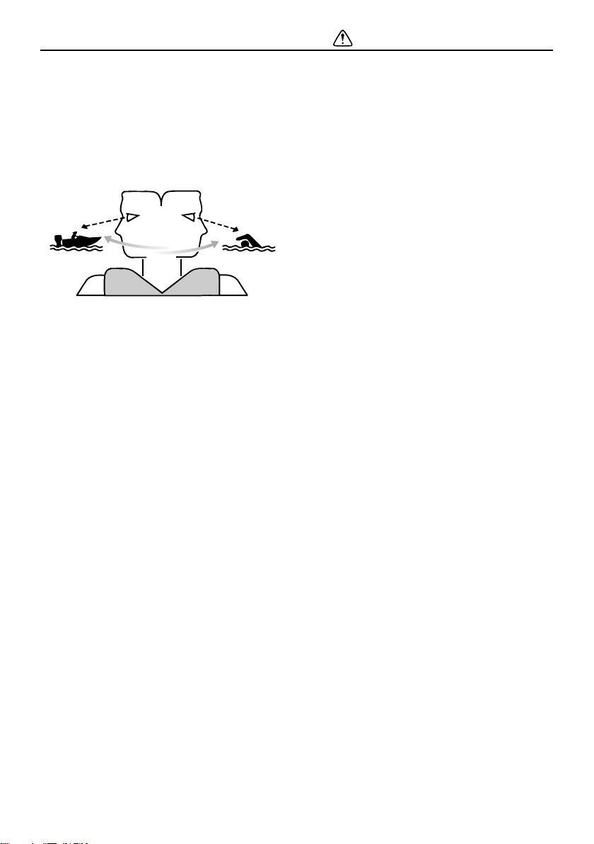
EMU33731
People in the water
Always watch carefully for people in the water, such as swimmers, skiers, or divers,
whenever the engine is running. When
someone is in the water near the boat, shift
into neutral and stop the engine.
Stay away from swimming areas. Swimmers
can be hard to see.
The propeller can keep moving even when
the motor is in neutral. Stop the engine when
a person is in the water near you.
EMU33751
Passengers
Consult your boat manufacturer’s instructions for details about appropriate passenger
locations in your boat and be sure all passengers are positioned properly before accelerating and when operating above an idle
speed. Standing or sitting in non-designated
locations may result in being thrown either
overboard or within the boat due to waves,
wakes, or sudden changes in speed or direction. Even when people are positioned properly, alert your passengers if you must make
any unusual maneuver. Always avoid jumping waves or wakes.
EMU33760
Overloading
Do not overload the boat. Consult the boat
capacity plate or boat manufacturer for maximum weight and number of passengers. Be
sure that weight is properly distributed according to the boat manufacturers instructions. Overloading or incorrect weight
distribution can compromise the boats handling and lead to an accident, capsizing or
2
Safety information
ZMU06025
swamping.
EMU33772
Avoid collisions
Scan constantly for people, objects, and other boats. Be alert for conditions that limit your
visibility or block your vision of others.
Operate defensively at safe speeds and
keep a safe distance away from people, objects, and other boats.
Do not follow directly behind other boats or
waterskiers.
Avoid sharp turns or other maneuvers that
make it hard for others to avoid you or understand where you are going.
Avoid areas with submerged objects or
shallow water.
Ride within your limits and avoid aggres-
sive maneuvers to reduce the risk of loss
of control, ejection, and collision.
Take early action to avoid collisions. Re-
member, boats do not have brakes, and
stopping the engine or reducing throttle
can reduce the ability to steer. If you are
not sure that you can stop in time before
hitting an obstacle, apply throttle and turn
in another direction.
EMU33790
Weather
Stay informed about the weather. Check
weather forecasts before boating. Avoid
boating in hazardous weather.
EMU33880
Passenger training
Make sure at least one other passenger is
trained to operate the boat in the event of an
emergency.
EMU33890
Boating safety publications
Be informed about boating safety. Additional
publications and information can be obtained
from many boating organizations.
EMU33600
Laws and regulations
Know the marine laws and regulations where
you will be boating- and obey them. Several
sets of rules prevail according to geographic
location, but all are basically the same as the
International Rules of the Road.
3
General information
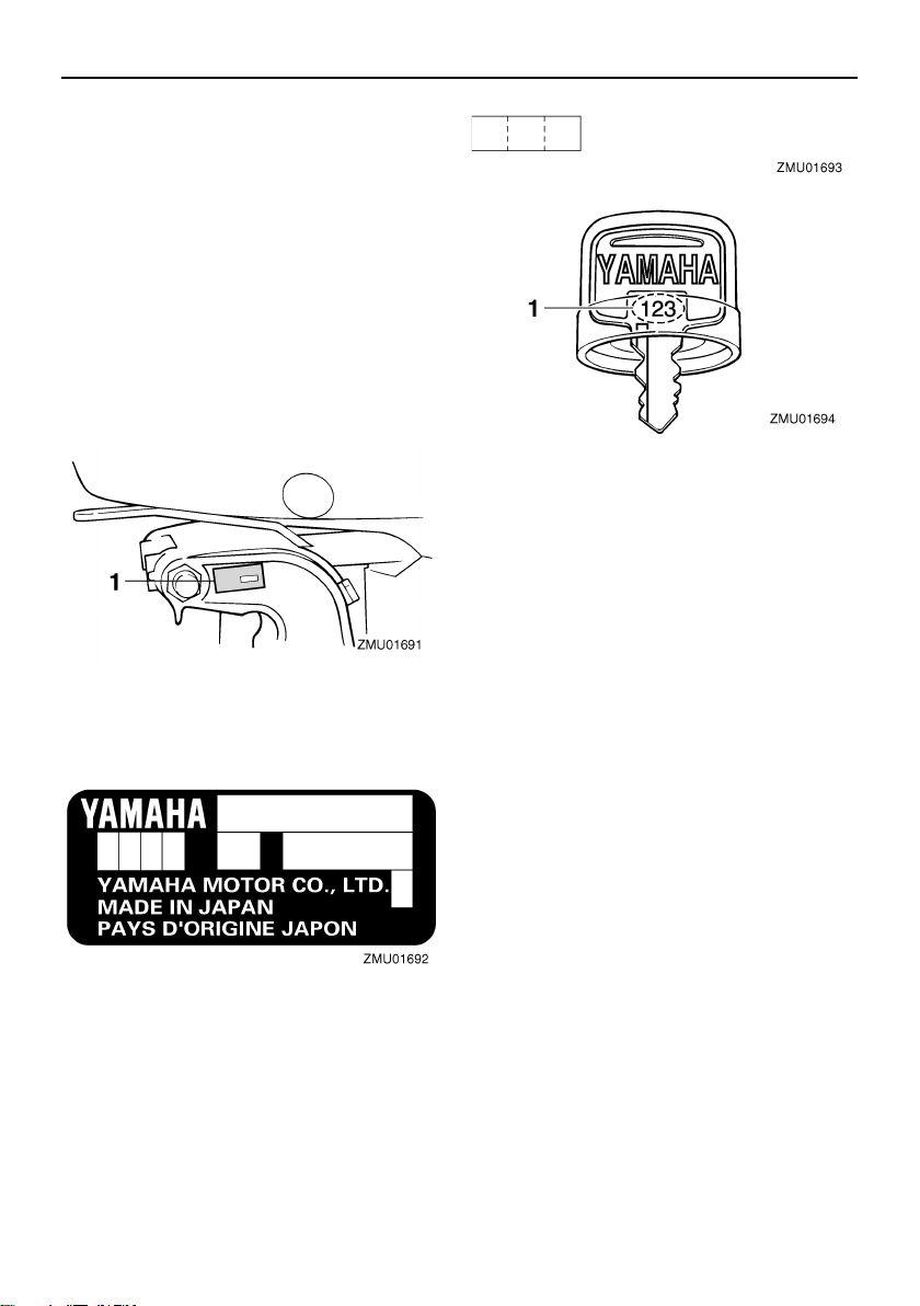
EMU25171
Identification numbers record
EMU25184
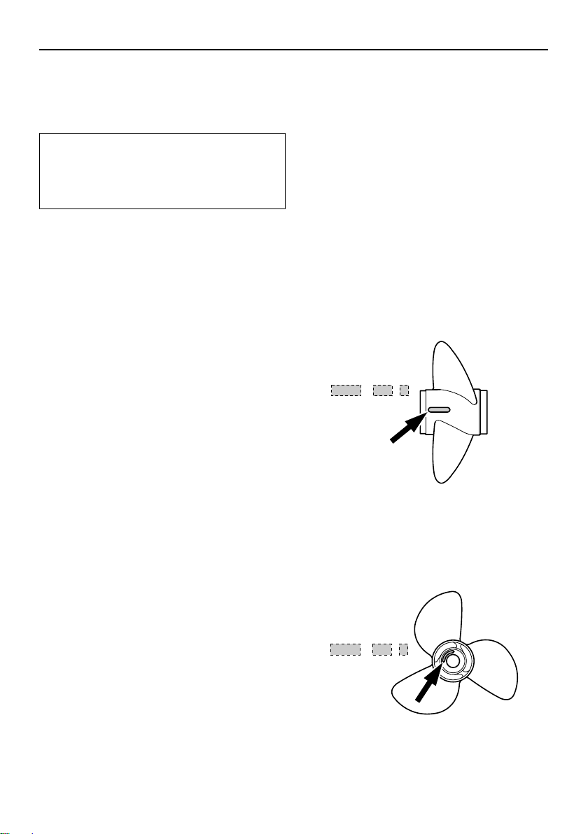
Outboard motor serial number
The outboard motor serial number is
stamped on the label attached to the port
side of the clamp bracket.
Record your outboard motor serial number in
the spaces provided to assist you in ordering
spare parts from your Yamaha dealer or for
reference in case your outboard motor is stolen.
1. Outboard motor serial number location
EMU25191
Key number
If a main key switch is equipped with the motor, the key identification number is stamped
on your key as shown in the illustration.
Record this number in the space provided for
reference in case you need a new key.
1. Key number
EMU37291
EC Declaration of Conformity
(DoC)
This outboard motor conforms to certain portions of the European Parliament directive
relating to machinery.
Each conformed outboard motor accompanied with EC DoC.EC DoC contains the following information;
Name of Engine Manufacture
Model name
Product code of model (Approved model
code)
Code of conformed directives
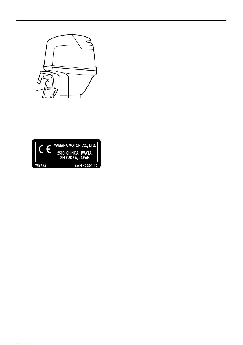
EMU25205
CE Marking
Outboard motors affixed with this “CE”marking conform with the directives of; 98/37/EC,
94/25/EC - 2003/44/EC and 2004/108/EC.
4
ZMU04704
1
ZMU06040
1. CE marking location
General information
5
General information
3
1
2
ZMU05712
EMU33523
Read manuals and labels
Before operating or working on this outboard motor:
Read this manual.
Read any manuals supplied with the boat.
Read all labels on the outboard motor and the boat.
If you need any additional information, contact your Yamaha dealer.
EMU33832
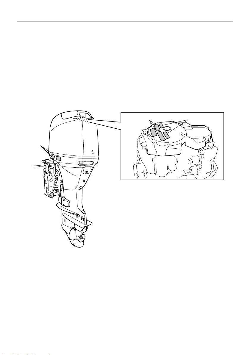
Warning labels
If these labels are damaged or missing, contact your Yamaha dealer for replacements.
F40D, F50F, F60C, FT50G, FT60D
6
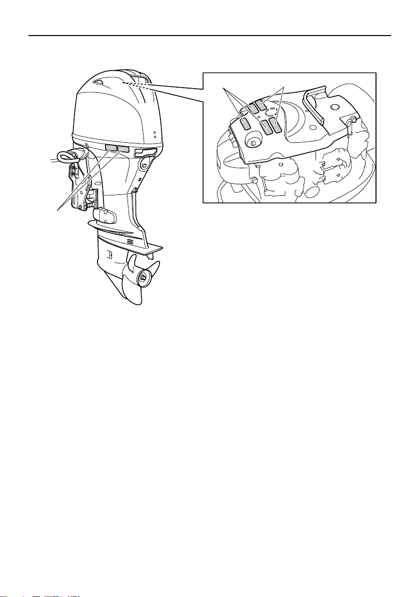
F40G, F70A
3
1
2
ZMU07077
General information
7
General information
WARNING
WARNING
WARNING
ZMU05706
1
2
3
EMU33912
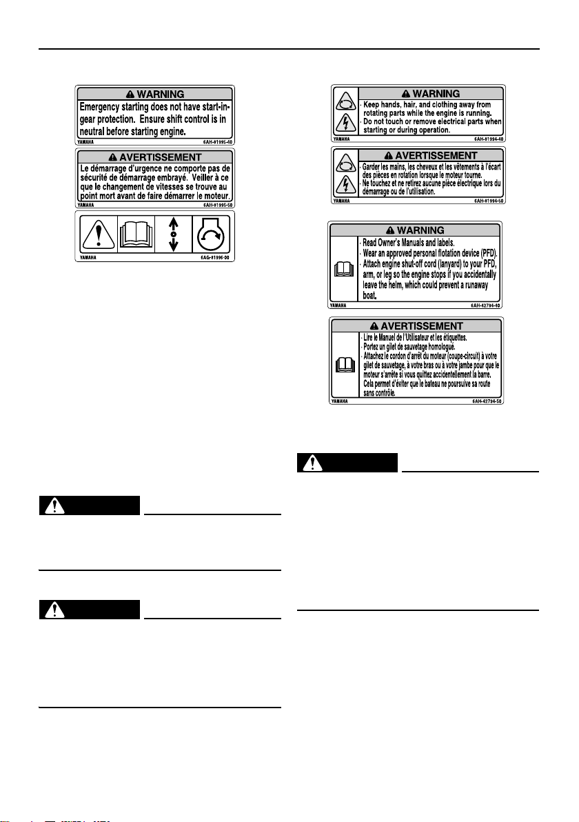
Contents of labels
The above warning labels mean as follows.
1
EWM01691
Emergency starting does not have startin-gear protection. Ensure shift control is
in neutral before starting engine.
2
EWM01681
Keep hands, hair, and clothing away
from rotating parts while the engine is
running.
Do not touch or remove electrical parts
when starting or during operation.
8
3
EWM01671
Read Owner’s Manuals and labels.
Wear an approved personal flotation
device (PFD).
Attach engine shut-off cord (lanyard) to
your PFD, arm, or leg so the engine
stops if you accidentally leave the
helm, which could prevent a runaway
boat.
General information
ZMU05696
ZMU05664
ZMU05665
ZMU05666
ZMU05667
ZMU05668
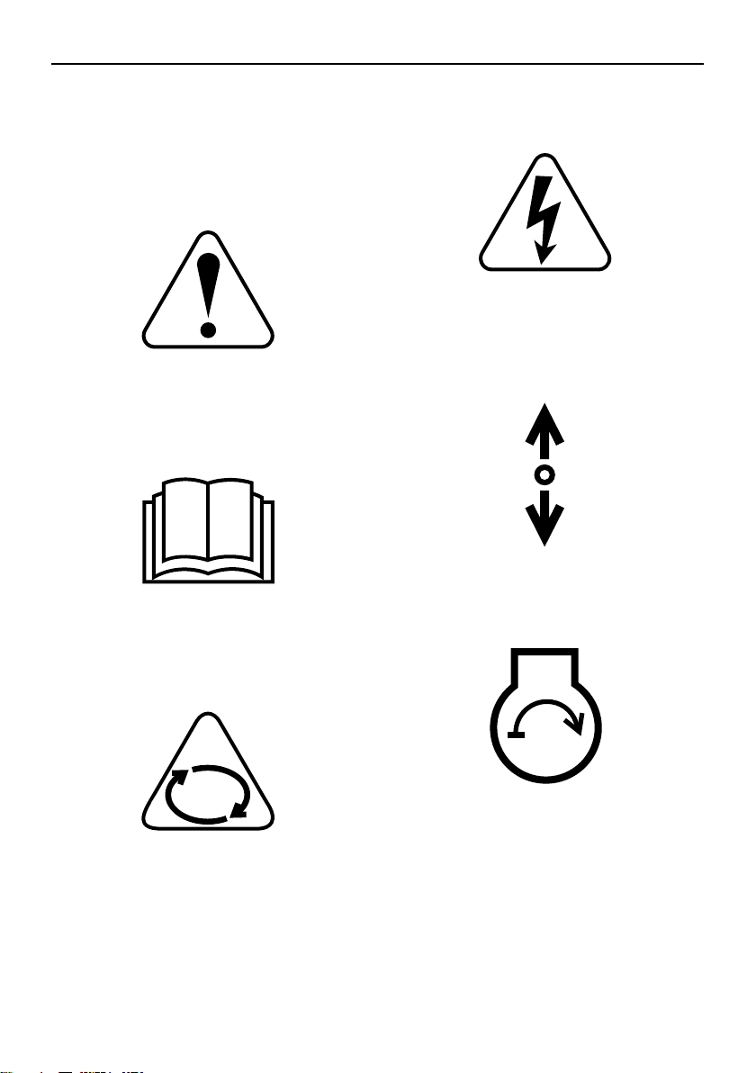
EMU33843
Symbols
The following symbols mean as follows.
Notice/Warning
Read Owner’s Manual
Electrical hazard
Remote control lever/gear shift lever operating direction, dual direction
Engine start/ Engine cranking
Hazard caused by continuous rotation
9

Specifications and requirements
TIP:
EMU34521
Specifications
“(AL)” stated in the specification data below
represents the numerical value for the aluminum propeller installed.
Likewise, “(SUS)” represents the value for
stainless steel propeller installed and “(PL)”
for plastic propeller installed.
EMU2821K
Dimension:
Overall length:
F40DET 706 mm (27.8 in)
F40GET 698 mm (27.5 in)
F50FED 706 mm (27.8 in)
F50FET 706 mm (27.8 in)
F60CET 706 mm (27.8 in)
F70AET 713 mm (28.1 in)
FT50GET 706 mm (27.8 in)
FT60DET 706 mm (27.8 in)
Overall width:
F40DET 385 mm (15.2 in)
F40GET 386 mm (15.2 in)
F50FED 385 mm (15.2 in)
F50FET 385 mm (15.2 in)
F60CET 385 mm (15.2 in)
F70AET 386 mm (15.2 in)
FT50GET 385 mm (15.2 in)
FT60DET 385 mm (15.2 in)
Overall height L:
F40DET 1414 mm (55.7 in)
F40GET 1476 mm (58.1 in)
F50FED 1414 mm (55.7 in)
F50FET 1414 mm (55.7 in)
F60CET 1414 mm (55.7 in)
F70AET 1476 mm (58.1 in)
FT50GET 1455 mm (57.3 in)
FT60DET 1455 mm (57.3 in)
Overall height X:
F70AET 1590 mm (62.6 in)
FT60DET 1569 mm (61.8 in)
Transom height L:
F40DET 527 mm (20.7 in)
F40GET 534 mm (21.0 in)
F50FED 527 mm (20.7 in)
F50FET 527 mm (20.7 in)
F60CET 527 mm (20.7 in)
F70AET 534 mm (21.0 in)
FT50GET 530 mm (20.9 in)
FT60DET 530 mm (20.9 in)
Transom height X:
F70AET 648 mm (25.5 in)
FT60DET 644 mm (25.4 in)
Weight (AL) L:
F40DET 113.0 kg (249 lb)
F40GET 117.0 kg (258 lb)
F50FED 107.0 kg (236 lb)
F50FET 113.0 kg (249 lb)
F60CET 113.0 kg (249 lb)
F70AET 119.0 kg (262 lb)
FT50GET 118.0 kg (260 lb)
FT60DET 123.0 kg (271 lb)
Weight (AL) X:
F70AET 121.0 kg (267 lb)
FT60DET 127.0 kg (280 lb)
Performance:
Full throttle operating range:
F40DET 5000–6000 r/min
F40GET 5300–6300 r/min
F50FED 5000–6000 r/min
F50FET 5000–6000 r/min
F60CET 5000–6000 r/min
F70AET 5300–6300 r/min
FT50GET 5000–6000 r/min
FT60DET 5000–6000 r/min
Maximum output:
F40DET 29.4 kW@5500 r/min
(40 HP@5500 r/min)
F40GET 29.4 kW@5800 r/min
(40 HP@5800 r/min)
F50FED 36.8 kW@5500 r/min
10

Specifications and requirements
(50 HP@5500 r/min)
F50FET 36.8 kW@5500 r/min
(50 HP@5500 r/min)
F60CET 44.1 kW@5500 r/min
(60 HP@5500 r/min)
F70AET 51.5 kW@5800 r/min
(70 HP@5800 r/min)
FT50GET 36.8 kW@5500 r/min
(50 HP@5500 r/min)
FT60DET 44.1 kW@5500 r/min
(60 HP@5500 r/min)
Idle speed (in neutral):
750 50 r/min
Engine:
Type:
4-stroke L
Displacement:
996.0 cm
Bore stroke:
65.0 75.0 mm (2.56 2.95 in)
Ignition system:
TCI
Spark plug (NGK):
F40DET DPR6EB-9
F40GET LKR7E
F50FED DPR6EB-9
F50FET DPR6EB-9
F60CET DPR6EB-9
F70AET LKR7E
FT50GET DPR6EB-9
FT60DET DPR6EB-9
Spark plug gap:
0.8–0.9 mm (0.031–0.035 in)
Control system:
Remote control
Starting system:
Electric starter
Starting carburetion system:
Electronic fuel injection
Valve clearance (cold engine) IN:
0.15–0.25 mm (0.0059–0.0098 in)
3
Valve clearance (cold engine) EX:
0.25–0.35 mm (0.0098–0.0138 in)
Min. cold cranking amps (CCA/EN):
430.0 A
Min. rated capacity (20HR/IEC):
70 Ah
Maximum generator output:
F40DET 16 A
F40GET 15 A
F50FED 16 A
F50FET 16 A
F60CET 16 A
F70AET 15 A
FT50GET 16 A
FT60DET 16 A
Drive unit:
Gear positions:
Forward-neutral-reverse
Gear ratio:
F40DET 1.85(24/13)
F40GET 2.33(28/12)
F50FED 1.85(24/13)
F50FET 1.85(24/13)
F60CET 1.85(24/13)
F70AET 2.33(28/12)
FT50GET 2.33(28/12)
FT60DET 2.33(28/12)
Trim and tilt system:
F40DET Power trim and tilt
F40GET Power trim and tilt
F50FED Hydro tilt
F50FET Power trim and tilt
F60CET Power trim and tilt
F70AET Power trim and tilt
FT50GET Power trim and tilt
FT60DET Power trim and tilt
Propeller mark:
F40DET G
F50FED G
F50FET G
F60CET G
11

Specifications and requirements
F70AET K
FT50GET K
FT60DET K
Fuel and oil:
Recommended fuel:
Regular unleaded gasoline
Min. research octane:
90
Fuel tank capacity:
25 L (6.60 US gal, 5.50 Imp.gal)
Recommended engine oil:
4-stroke outboard motor oil
Recommended engine oil grade 1:
SAE 10W-30/10W-40/5W-30
API SE/SF/SG/SH/SJ/SL
Total engine oil quantity (oil pan capacity):
2.5 L (2.64 US qt, 2.20 Imp.qt)
Lubrication:
Wet sump
Recommended gear oil:
Hypoid gear oil SAE#90
Gear oil quantity:
F40DET 0.430 L
(0.455 US qt, 0.378 Imp.qt)
F40GET 0.670 L
(0.708 US qt, 0.590 Imp.qt)
F50FED 0.430 L
(0.455 US qt, 0.378 Imp.qt)
F50FET 0.430 L
(0.455 US qt, 0.378 Imp.qt)
F60CET 0.430 L
(0.455 US qt, 0.378 Imp.qt)
F70AET 0.670 L
(0.708 US qt, 0.590 Imp.qt)
FT50GET 0.670 L
(0.708 US qt, 0.590 Imp.qt)
FT60DET 0.670 L
(0.708 US qt, 0.590 Imp.qt)
Tightening torque for engine:
Spark plug:
F40DET 18.0 Nm
(1.84 kgf-m, 13.3 ft-lb)
F40GET 17.0 Nm
(1.73 kgf-m, 12.5 ft-lb)
F50FED 18.0 Nm
(1.84 kgf-m, 13.3 ft-lb)
F50FET 18.0 Nm
(1.84 kgf-m, 13.3 ft-lb)
F60CET 18.0 Nm
(1.84 kgf-m, 13.3 ft-lb)
F70AET 17.0 Nm
(1.73 kgf-m, 12.5 ft-lb)
FT50GET 18.0 Nm
(1.84 kgf-m, 13.3 ft-lb)
FT60DET 18.0 Nm
(1.84 kgf-m, 13.3 ft-lb)
Propeller nut:
F40DET 35.0 Nm
(3.57 kgf-m, 25.8 ft-lb)
F40GET 34.0 Nm
(3.47 kgf-m, 25.1 ft-lb)
F50FED 35.0 Nm
(3.57 kgf-m, 25.8 ft-lb)
F50FET 35.0 Nm
(3.57 kgf-m, 25.8 ft-lb)
F60CET 35.0 Nm
(3.57 kgf-m, 25.8 ft-lb)
F70AET 34.0 Nm
(3.47 kgf-m, 25.1 ft-lb)
FT50GET 35.0 Nm
(3.57 kgf-m, 25.8 ft-lb)
FT60DET 35.0 Nm
(3.57 kgf-m, 25.8 ft-lb)
Engine oil drain bolt:
F40DET 28.0 Nm
(2.86 kgf-m, 20.7 ft-lb)
F40GET 27.0 Nm
(2.75 kgf-m, 19.9 ft-lb)
F50FED 28.0 Nm
(2.86 kgf-m, 20.7 ft-lb)
F50FET 28.0 Nm
(2.86 kgf-m, 20.7 ft-lb)
12
Specifications and requirements
WARNING
WARNING
WARNING
F60CET 28.0 Nm
(2.86 kgf-m, 20.7 ft-lb)
F70AET 27.0 Nm
(2.75 kgf-m, 19.9 ft-lb)
FT50GET 28.0 Nm
(2.86 kgf-m, 20.7 ft-lb)
FT60DET 28.0 Nm
(2.86 kgf-m, 20.7 ft-lb)
Engine oil filter:
18.0 Nm (1.84 kgf-m, 13.3 ft-lb)
Noise and vibration level:
Operator sound pressure level (ICOMIA
39/94 and 40/94):
F40DET 78.1 dB(A)
F40GET 83.9 dB(A)
F50FED 78.1 dB(A)
F50FET 78.1 dB(A)
F60CET 78.1 dB(A)
F70AET 83.9 dB(A)
FT50GET 78.1 dB(A)
FT60DET 78.1 dB(A)
EMU33554
Installation requirements
EMU33564
Boat horsepower rating
EWM01560
Overpowering a boat can cause severe
instability.
Before installing the outboard motor(s), confirm that the total horsepower of your outboard motor(s) does not exceed the boats
maximum horsepower rating. See the boat’s
capacity plate or contact the manufacturer.
EMU33571
Mounting motor
EWM01570
control, or fire hazards.
Because the motor is very heavy, spe-
cial equipment and training is required
to mount it safely.
Your dealer or other person experienced in
proper rigging should mount the motor using
correct equipment and complete rigging instructions. For further information, see page
46.
EMU38580
Yamaha Security System
This outboard motor is equipped with the
Yamaha Security System to protect against
theft, which consists of the receiver and remote control transmitter. The engine can not
be started if the security system is in the lock
mode, and only be started in the unlock
mode. Consult your Yamaha dealer for installation of the receiver.
EMU33581
Remote control requirements
EWM01580
If the engine starts in gear, the boat can
move suddenly and unexpectedly, possibly causing a collision or throwing
passengers overboard.
If the engine ever starts in gear, the
start-in-gear protection device is not
working correctly and you should discontinue using the outboard. Contact
your Yamaha dealer.
The remote control unit must be equipped
with a start-in-gear protection device(s). This
device prevents the engine from starting unless it is in neutral.
Improper mounting of the outboard mo-
tor could result in hazardous conditions such as poor handling, loss of
13
Specifications and requirements
ZMU04606
-
x
123
ZMU04607
-
x
123
EMU25694
Battery requirements
EMU25721
Battery specifications
Minimum cold cranking amps (CCA/EN):
430.0 A
Minimum rated capacity (20HR/IEC):
70 Ah
The engine cannot be started if battery voltage is too low.
EMU36290
Mounting battery
Mount the battery holder securely in a dry,
well-ventilated, vibration-free location in the
boat. WARNING! Do not put flammable
items, or loose heavy or metal objects in
the same compartment as the battery.
Fire, explosion or sparks could result.
[EWM01820]
EMU36300
Multiple batteries
To connect multiple batteries, such as for
multiple engine configurations or for an accessory battery, consult your Yamaha dealer
about battery selection and correct wiring.
EMU34195
Propeller selection
Next to selecting an outboard motor, selecting the right propeller is one of the most important purchasing decisions a boater can
make. The type, size, and design of your propeller have a direct impact on acceleration,
top speed, fuel economy, and even engine
life. Yamaha designs and manufactures propellers for every Yamaha outboard motor
and every application.
Your outboard motor came with a Yamaha
propeller selected to perform well over a
range of applications, but there may be uses
where a different propeller would be more
appropriate.
Your Yamaha dealer can help you select the
right propeller for your boating needs. Select
a propeller that will allow the engine to reach
the middle or upper half of the operating
range at full throttle with the maximum boatload. Generally, select a larger pitch propeller for a smaller operating load and a smaller
pitch propeller for a heavier load. If you carry
loads that vary widely, select the propeller
that lets the engine run in the proper range
for your maximum load but remember that
you may need to reduce your throttle setting
to stay within the recommended engine
speed range when carrying lighter loads.
To check the propeller, see page 86.
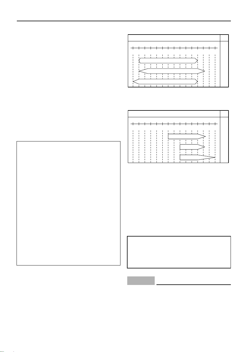
1. Propeller diameter in inches
2. Propeller pitch in inches
3. Type of propeller (propeller mark)
1. Propeller diameter in inches
14
Specifications and requirements
NOTICE
ZMU06854
122˚F
50˚C
104
40
86
30
68
SAE API
SE
SF
SG
SH
SJ
SL
20
50
10
32
0
14
-10
-4
-20
10W–30
10W–40
5W–30
ZMU06855
122˚F
50˚C
104
40
86
30
68
SAE API
SH
SJ
SL
20
50
10
32
0
14
-10
-4
-20
15W–40
20W–40
20W–50
2. Propeller pitch in inches
3. Type of propeller (propeller mark)
EMU25770
Start-in-gear protection
Yamaha outboard motors or Yamaha-approved remote control units are equipped
with start-in-gear protection device(s). This
feature permits the engine to be started only
when it is in neutral. Always select neutral
before starting the engine.
EMU41951
Engine oil requirements
Select an oil grade according to the average
temperatures in the area where the outboard
motor will be used.
Recommended engine oil:
4-stroke outboard motor oil
Recommended engine oil grade 1:
SAE 10W-30/10W-40/5W-30
API SE/SF/SG/SH/SJ/SL
Recommended engine oil grade 2:
SAE 15W-40/20W-40/20W-50
API SH/SJ/SL
Total engine oil quantity (oil pan capacity):
2.5 L (2.64 US qt, 2.20 Imp.qt)
Replacement engine oil quantity (at periodic maintenance):
Without oil filter replacement:
1.9 L (2.01 US qt, 1.67 Imp.qt)
With oil filter replacement:
2.1 L (2.22 US qt, 1.85 Imp.qt)
Recommended engine oil grade 1
Recommended engine oil grade 2
EMU36360
Fuel requirements
EMU36803
Gasoline
Use a good quality gasoline that meets the
minimum octane rating. If knocking or pinging occurs, use a different brand of gasoline
or premium unleaded fuel.
Recommended gasoline:
Regular unleaded gasoline with a minimum octane rating of 90 (Research
Octane Number).
If oil grades listed under Recommended engine oil grade 1 are not available, select an
alternative oil grade listed under Recommended engine oil grade 2.
ECM01981
Do not use leaded gasoline. Leaded
gasoline can seriously damage the engine.
Avoid getting water and contaminants
in the fuel tank. Contaminated fuel can
15
Specifications and requirements
cause poor performance or engine
damage. Use only fresh gasoline that
has been stored in clean containers.
Gasohol
There are two types of gasohol: gasohol containing ethanol (E10) and that containing
methanol. Ethanol can be used if the ethanol
content does not exceed 10% and the fuel
meets the minimum octane ratings. E85 is a
fuel containing 85% ethanol and must not be
used in your outboard motor. All ethanol
blends containing more than 10% ethanol
can cause fuel system damage or cause engine starting and running problems. Yamaha
does not recommend gasohol containing
methanol because it can cause fuel system
damage or engine performance problems.
It is recommended that you install a waterseparating marine fuel filter assembly (10 micron minimum) between your boat’s fuel tank
and outboard motor when using ethanol.
Ethanol is known to allow moisture to be absorbed into boat fuel tanks and systems.
Moisture in the fuel can cause corrosion of
metallic fuel system components, starting
and running complaints and require additional fuel system maintenance.
EMU36330
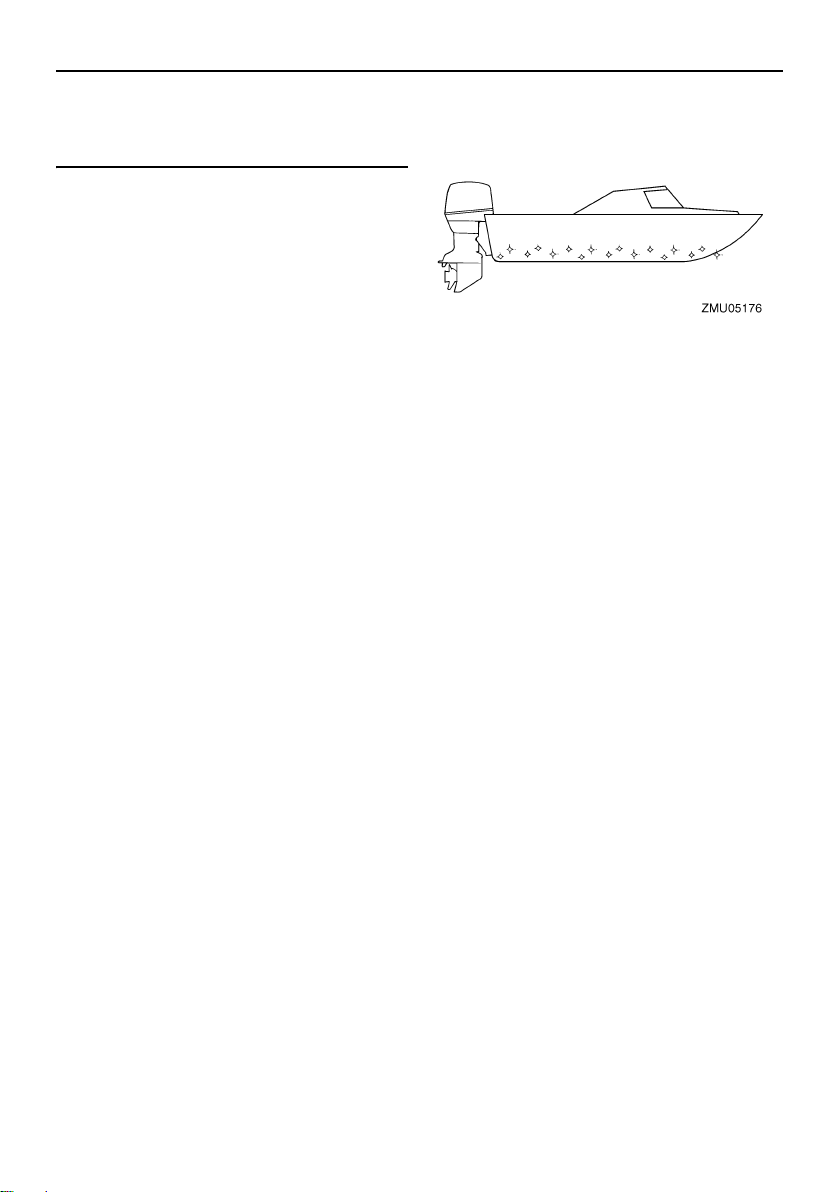
Anti-fouling paint
A clean hull improves boat performance. The
boat bottom should be kept as clean of marine growth as possible. If necessary, the
boat bottom can be coated with an anti-fouling paint approved for your area to inhibit
marine growth.
Do not use anti-fouling paint which includes
copper or graphite. These paints can cause
more rapid engine corrosion.
EMU36341
Motor disposal requirements
Never illegally discard (dump) the motor.
Yamaha recommends consulting the dealer
about discarding the motor.
EMU36352
Emergency equipment
Keep the following items onboard in case
there is trouble with the outboard motor.
A tool kit with assorted screwdrivers, pli-
ers, wrenches (including metric sizes), and
electrical tape.
Waterproof flashlight with extra batteries.
An extra engine shut-off cord (lanyard)
with clip.
Spare parts, such as an extra set of spark
plugs.
Consult your Yamaha dealer for details.
16
Components
TIP:
TRIP TIME BATT
Km/h
knot
mph
km
mile
SPEED
YAMAHA
set
mode
1
3
4
9
11
12
13
14
10
2
6
7
5
8
15
23
22
16
19
17 18
20 21
ZMU07563
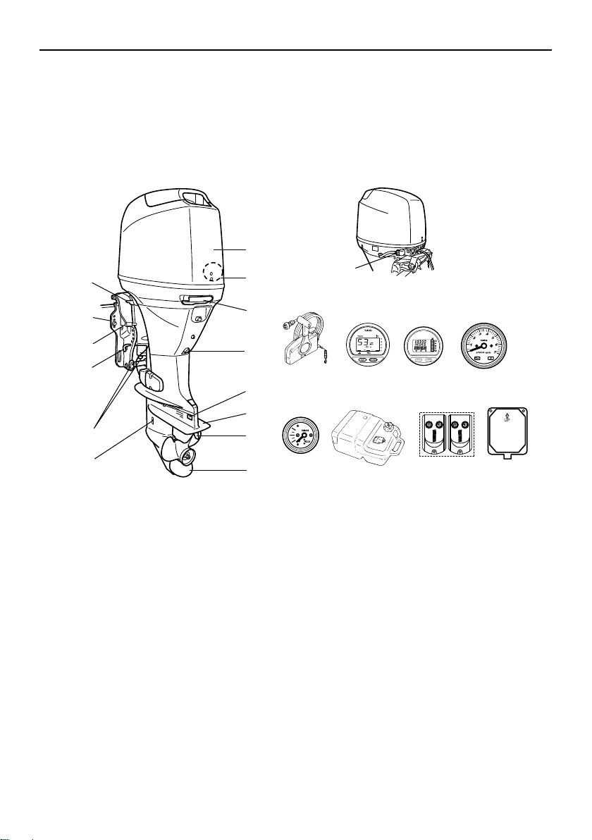
EMU2579Y
Components diagram
* May not be exactly as shown; also may not be included as standard equipment on all models (order from dealer).
F40D, F50F, F60C, FT50G, FT60D
1. Top cowling
2. Water separator
3. Cowling lock lever
4. Drain screw
5. Anode*
6. Anti-cavitation plate
7. Trim tab (anode)
8. Propeller*
9. Cooling water inlet
10. Anode(s)*
11. Trim rod*
12. Tilt lock lever*
13. Clamp bracket
14. Tilt support lever
15. Flushing device
16. Remote control box (side mount type)*
17. Digital tachometer*
18. Digital speedometer*
19. Tachometer*
20. Trim meter*
21. Fuel tank
22. Remote control transmitter
23. Receiver
17
Components
1
3
2
4
11
9
5
6
7
8
13
11
12
TRIP TIME BATT
Km/h
knot
mph
km
mile
SPEED
YAMAHA
set
mode
21
20
14
17
15 16
18
19
10
ZMU07075
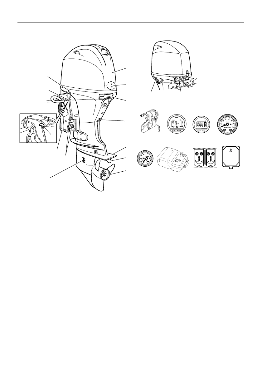
F40G, F70A
1. Top cowling
2. Water separator
3. Cowling lock lever
4. Drain screw
5. Anti-cavitation plate
6. Trim tab (anode)
7. Propeller*
8. Cooling water inlet
9. Anode(s)
10. Clamp bracket
11. Tilt support lever
12. Power trim and tilt switch
13. Flushing device
14. Remote control box (side mount type)*
15. Digital tachometer*
16. Digital speedometer*
17. Tachometer*
18. Trim meter*
19. Fuel tank
20. Remote control transmitter
18
21. Receiver
WARNING
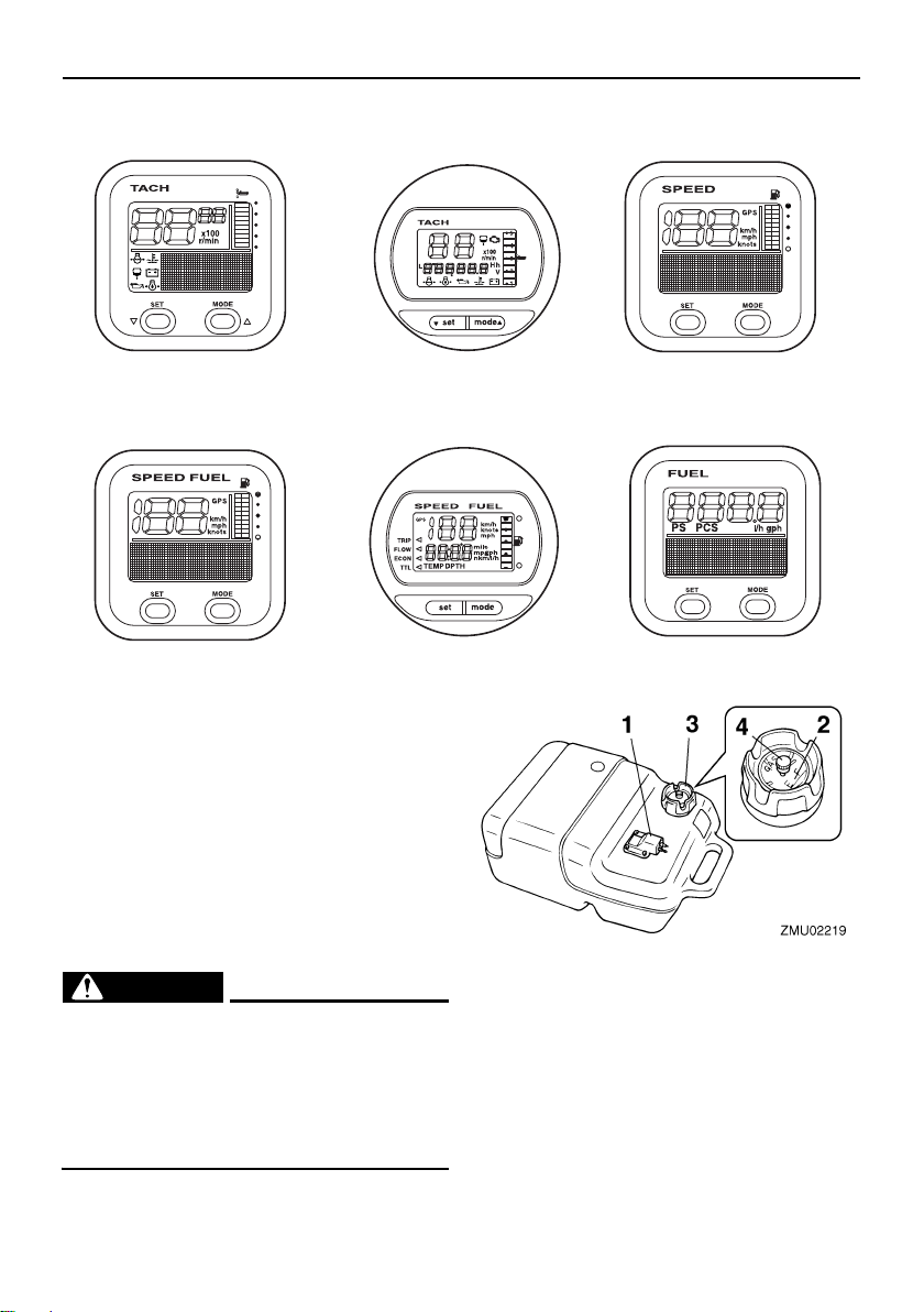
1
4
6
3
2
5
ZMU05429
1. Tachometer unit (Square type)*
2. Tachometer unit (Round type)*
3. Speedometer unit (Square type)*
4. Speed & fuel meter unit (Square type)*
5. Speed & fuel meter unit (Round type)*
6. Fuel management meter (Square type)*
Components
EMU25802
Fuel tank
If your model was equipped with a portable
fuel tank, its function is as follows.
EWM00020
The fuel tank supplied with this engine is
its dedicated fuel reservoir and must not
be used as a fuel storage container. Commercial users should conform to relevant
licensing or approval authority regulations.
1. Fuel joint
2. Fuel gauge
3. Fuel tank cap
4. Air vent screw
EMU25830
Fuel joint
This joint is used to connect the fuel line.
19
Components
NOTICE
TIP:
ZMU06455
EMU25841
Fuel gauge
This gauge is located on either the fuel tank
cap or on the fuel joint base. It shows the approximate amount of fuel remaining in the
tank.
EMU25850
Fuel tank cap
This cap seals the fuel tank. When removed,
the tank can be filled with fuel. To remove the
cap, turn it counterclockwise.
EMU25860
Air vent screw
This screw is on the fuel tank cap. To loosen
the screw, turn it counterclockwise.
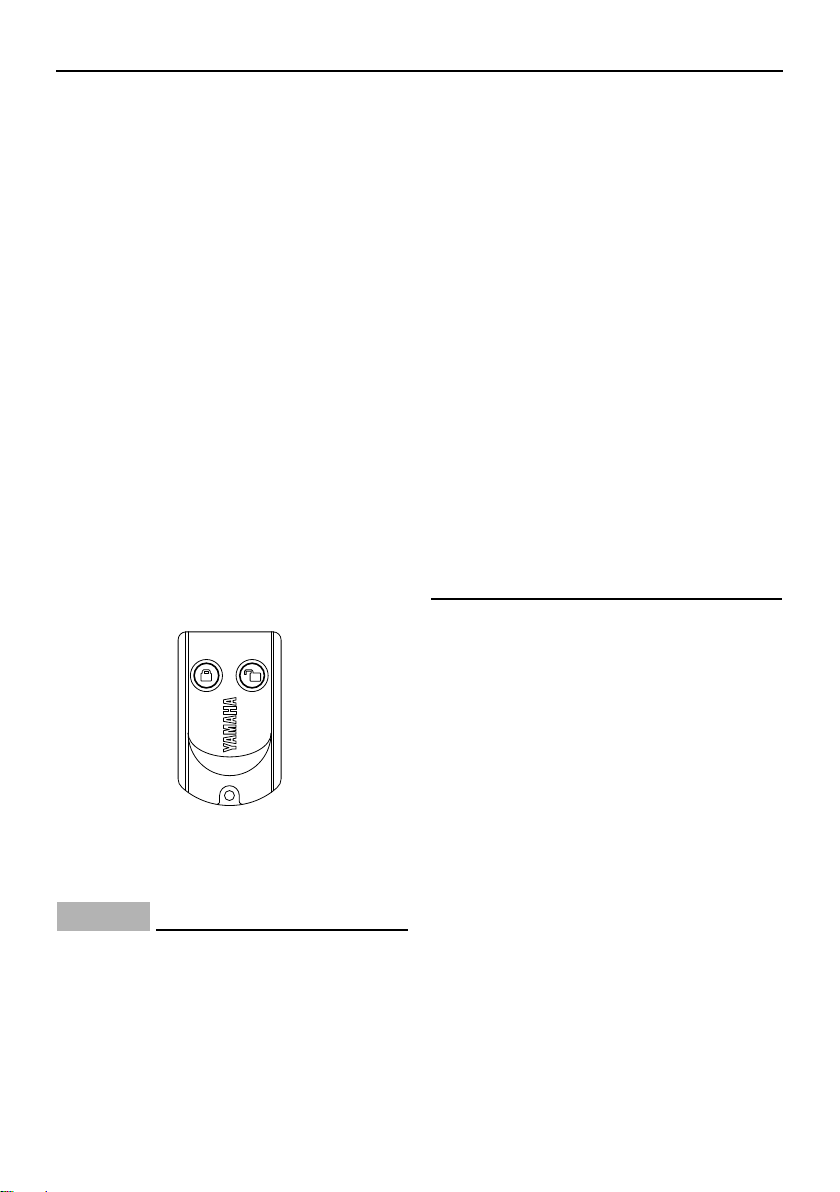
EMU38591
Remote control transmitter
The lock and unlock modes of the Yamaha
Security System are selected using the remote control transmitter. While the engine is
running, input from the remote control transmitter is not received.
Store the remote control transmitter carefully
so it will not be lost.
ECM02100
The remote control transmitter is not
completely waterproof. Do not submerge the transmitter or operate it underwater. If the transmitter is
submerged, dry it with a soft, dry cloth,
and then check that it is operating prop-
erly. If the transmitter is not operating
properly, contact a Yamaha dealer.
Keep the remote control transmitter
away from high temperatures and do
not place it in direct sunlight.
Do not drop the remote control trans-
mitter, subject it to strong shocks, or
place any heavy items on it.
Use a soft, dry cloth to clean the remote
control transmitter. Do not use detergent, alcohol, or other chemicals.
Do not attempt to disassemble the re-
mote control transmitter yourself. Otherwise, the transmitter may not operate
properly. If the transmitter needs a new
battery, contact a Yamaha dealer.
If you have lost the remote control
transmitter, consult your Yamaha dealer. Keep the least 2 transmitters at all
the time. If you have lost both transmitters, consult your Yamaha dealer.
Since the receiver is programmed to rec-
ognize the internal code from this transmitter only, the security system setting can
only be changed with this transmitter. If the
remote control transmitter does not operate properly, contact a Yamaha dealer.
Replace the battery cell after 1 year, and
every two years thereafter as a standard
measure.
Refer to local hazardous waste regulations
when disposing of transmitter batteries.
The Yamaha Security System permits to
register up to 5 remote control transmitters. Consult your yamaha dealer for details.
EMU38601
Receiver
The receiver control the ECM (Electronic
control module) to prevent the engine from
20
Components
12
ZMU06456
starting. Consult your Yamaha dealer for installation of the receiver.
EMU38611
Yamaha Security System lock and
unlock mode
The Yamaha Security System settings are
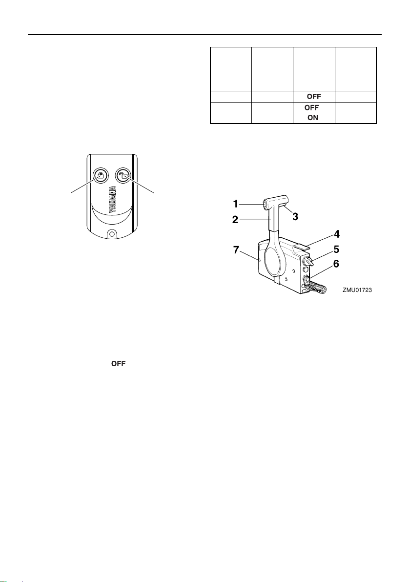
selected by pressing the lock or unlock button on the remote control transmitter briefly.
1. Lock button
2. Unlock button
LOCK
When the lock button on the remote control
transmitter is pressed briefly, the beeper
sounds once. This indicates the lock mode is
selected and the engine cannot be started.
The lock mode is selected only when the
main switch is in the “ ” (off) position. The
engine cranks but can not be started while
the Yamaha Security System is on lock
mode.
UNLOCK
When the unlock button on the remote control transmitter is pressed briefly, the beeper
sounds twice. This indicates the unlock
mode is selected and the engine can be
started.
Yamaha
Security
System
mode
Lock 1 beep
Unlock 2 beeps
EMU26181
Number
of beeps
Main
switch
“”
“”/“
Engine
can be
started
NO
”
YES
Remote control box
The remote control lever actuates both the
shifter and the throttle. The electrical switches are mounted on the remote control box.
1. Power trim and tilt switch
2. Remote control lever
3. Neutral interlock trigger
4. Neutral throttle lever
5. Main switch
6. Engine shut-off switch
7. Throttle friction adjuster
EMU26190
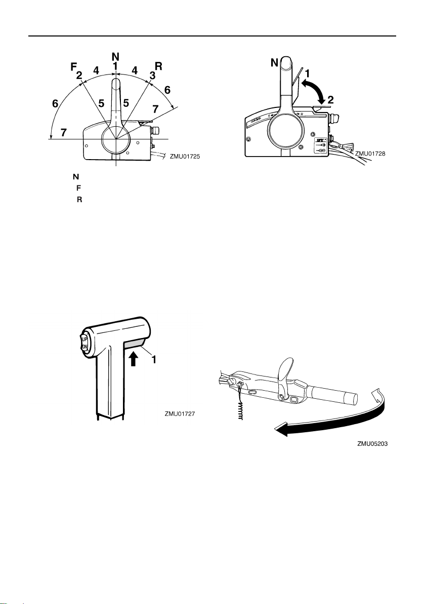
Remote control lever
Moving the lever forward from the neutral position engages forward gear. Pulling the lever back from neutral engages reverse. The
engine will continue to run at idle until the lever is moved about 35 (a detent can be felt).
Moving the lever farther opens the throttle,
and the engine will begin to accelerate.
21
Components
TIP:
1. Neutral “ ”
2. Forward “ ”
3. Reverse “ ”
4. Shift
5. Fully closed
6. Throttle
7. Fully open
EMU26201
Neutral interlock trigger
To shift out of neutral, first pull the neutral interlock trigger up.
1. Neutral interlock trigger
EMU26212
Neutral throttle lever
To open the throttle without shifting into either forward or reverse, put the remote control lever in the neutral position and lift the
neutral throttle lever.
1. Fully open
2. Fully closed
The neutral throttle lever will operate only
when the remote control lever is in neutral.
The remote control lever will operate only
when the neutral throttle lever is in the closed
position.
EMU25913
Tiller handle
To change direction, move the tiller handle to
the left or right as necessary.
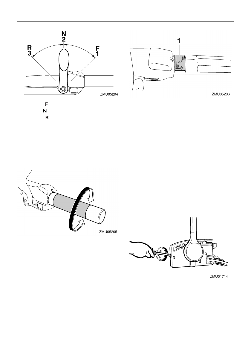
EMU25924
Gear shift lever
Move the gear shift lever forward to engage
the forward gear or rearward to engage the
reverse gear.
22
Components
1. Forward “ ”
2. Neutral “ ”
3. Reverse “ ”
EMU25942
Throttle grip
The throttle grip is on the tiller handle. Turn
the grip counterclockwise to increase speed
and clockwise to decrease speed.
EMU25962
Throttle indicator
The fuel consumption curve on the throttle
indicator shows the relative amount of fuel
consumed for each throttle position. Choose
the setting that offers the best performance
and fuel economy for the desired operation.
1. Throttle indicator
EMU25976
Throttle friction adjuster
A friction device provides adjustable resistance to movement of the throttle grip or the
remote control lever, and can be set according to operator preference.
To increase resistance, turn the adjuster
clockwise. To decrease resistance, turn the
adjuster counterclockwise. WARNING! Do
not overtighten the friction adjuster. If
there is too much resistance, it could be
difficult to move the remote control lever
or throttle grip, which could result in an
accident.
[EWM00032]
23
Components
When constant speed is desired, tighten the
adjuster to maintain the desired throttle setting.
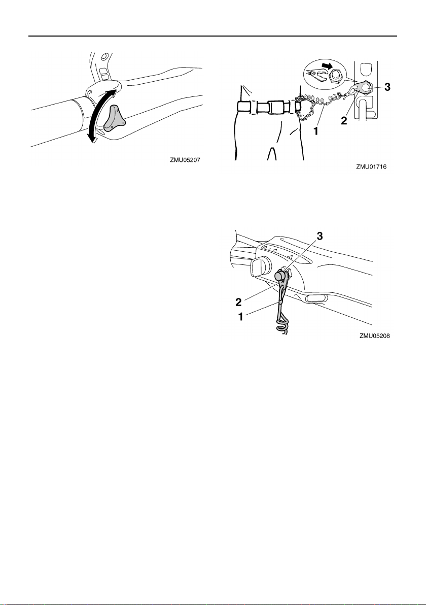
EMU25995
Engine shut-off cord (lanyard) and
clip
The clip must be attached to the engine shutoff switch for the engine to run. The cord
should be attached to a secure place on the
operator’s clothing, or arm or leg. Should the
operator fall overboard or leave the helm, the
cord will pull out the clip, stopping ignition to
the engine. This will prevent the boat from
running away under power. WARNING! At-
tach the engine shut-off cord to a secure
place on your clothing, or your arm or leg
while operating. Do not attach the cord to
clothing that could tear loose. Do not
route the cord where it could become entangled, preventing it from functioning.
Avoid accidentally pulling the cord during normal operation. Loss of engine
power means the loss of most steering
control. Also, without engine power, the
boat could slow rapidly. This could cause
people and objects in the boat to be
thrown forward.
[EWM00122]
1. Cord
2. Clip
3. Engine shut-off switch
1. Cord
2. Clip
3. Engine shut-off switch
EMU26003
Engine stop button
The engine stop button stops the engine
when the button is pushed.
24
 Loading...