

Yamaha F-20 User Manual
GUITAR AMPLIFIER
Owner’s Manual
Thank you for purchasing a Yamaha F-20 Guitar Amplifier.
To get the best results and longest life out of your F-20, we recommend that you
carefully read this manual, and keep it in a safe place for future reference.
Precautions
● To avoid possible damage do not expose the unit to:
• direct sunlight
• very high or low temperature/humidity
• sand or excessive dust
* Especially inside a vehicle, the temperature may rise
excessively — do not leave the F-20 in your parked car on a
sunny day!
● Before connecting/disconnecting cables or turning the unit on/off, be
sure to set the VOLUME/MASTER VOL. control on the F-20 to 0.
● Keep the F-20 away from neon signs or fluorescent lighting to prevent
noise pickup.
Specifications
Rated Output Power : 20 W
Speaker : 20 cm x 1
Controls : VOLUME, GAIN, MASTER VOL., TREBLE, MIDDLE, BASS,
CH SELECT switch (A/B)
Input/Output Terminals : INPUT, AUX IN, PHONES
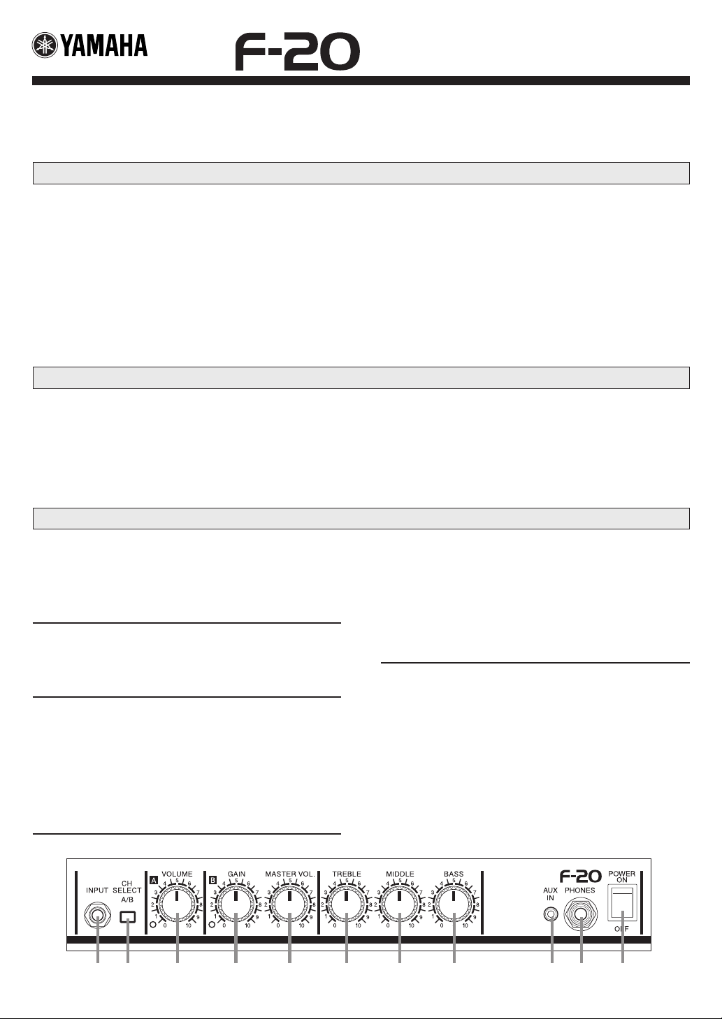
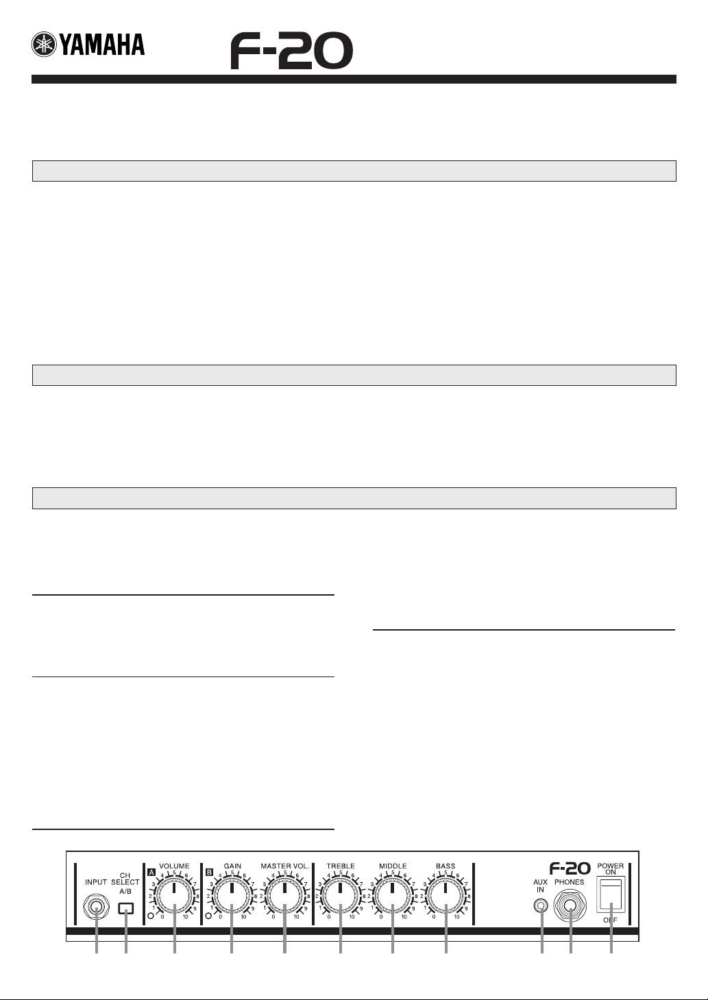
Control Panel
q INPUT : Connect your guitar to this jack.
w CH SELECT A/B (Channel Select Switch A/B) : Depress
the switch (>) to select Channel B which, can be used to create
distortion. When the switch is in its raised position (?), Channel A is
selected producing a clean, distortion free tone.
A Channel
e VOLUME : This knob controls the volume level of Channel A. This
knob functions only when Channel A is selected (?) with the CH
SELECT switch (the Channel A LED will light).
B Channel
r GAIN : This knob is used to control the amount of distortion. Rotate
the knob to the right to increase distortion. This knob functions only
when Channel B is selected (>) with the CH SELECT switch (the
Channel B LED will light).
t MASTER VOL. : This knob is used to control the volume level of
Channel B. This knob functions only when Channel B is selected (>)
with the CH SELECT switch (the Channel B LED will light).
● Handle the unit carefully — never apply excessive force to the
controls and avoid dropping the unit.
● For safety, always remove the power plug from the AC wall outlet if
there is any danger of lightning striking in your area.
● To prevent damage and possibly electrical shock, never open the
case and tamper with the internal circuitry.
● Never use solvents such as benzene or thinner to clean the F-20.
Wipe clean with a soft, dry cloth.
Power Requirements : U.S. and Canadian models : 120V, 60Hz
General model : 230V, 50Hz
Dimensions (W x H x D) : 357 x 330 x 197 mm (14.1" x 13" x 7.8")
Weight : 6.5 kg (14 lbs 5 oz)
* Specifications and external appearance are subject to change without notice.
Tone Controls
y TREBLE : This knob controls the level of the amplifier’s high fre-
quencies.
u MIDDLE : This knob controls the level of the amplifier’s mid fre-
quencies.
i BASS : This knob controls the level of the amplifier’s low frequen-
cies.
o AUX IN : Connect the output of an external audio device such as a
CD, MD, cassette deck, etc, to this jack to listen to audio playback of
the device, along with your guitar, through the F-20 amplifier.
* Use the volume control on the audio device to control its volume level.
!0 PHONES : Connect a pair of headphones to this jack.
* The speaker will produce no sound when a pair of headphones is con-
nected to this jack.
!1 POWER : This is the amplifier’s power switch. When the switch is
ON, the LED lamp of the channel currently selected with the CH SELECT switch will light.
w e r t y u i o !0 !1q

IMPORTANT SAFETY INSTRUCTIONS
INFORMATION RELATING TO PERSONAL INJURY, ELECTRICAL SHOCK, AND FIRE HAZARD
POSSIBILITIES HAS BEEN INCLUDED IN THIS LIST.
WARNING- When using any electrical or electronic product, basic
precautions should always be followed. These precautions include, but are
not limited to, the following:
1. Read all Safety Instructions, Installation Instructions, Special Mes-
sage Section items, and any Assembly Instructions found in this manual
BEFORE making any connections, including connection to the main
supply.
2. Do not attempt to service this product beyond that described in the
user-maintenance instructions. All other servicing should be referred to
qualified service personnel.
3. Main Power Supply Verification: Yamaha products are manufac-
tured specifically for the supply voltage in the area where they are to be
sold. If you should move, or if any doubt exists about the supply voltage in
your area, please contact your dealer for supply voltage verification and (if
applicable) instructions. The required supply voltage is printed on the name
plate. For name plate location, please refer to the graphic found in the
Special Message Section of this manual.
4. DANGER-Grounding Instructions: This product must be grounded
and therefore has been equipped with a three pin attachment plug. If this
product should malfunction, the ground pin provides a path of low resistance for electrical current, reducing the risk of electrical shock. If your
wall socket will not accommodate this type plug, contact an electrician to
have the outlet replaced in accordance with local electrical codes. Do NOT
modify the plug or change the plug to a different type!
5. WARNING: Do not place this product or any other objects on the
power cord or place it in a position where anyone could walk on, trip over,
or roll anything over power or connecting cords of any kind. The use of an
extension cord is not recommended! If you must use an extension cord, the
minimum wire size for a 25' cord (or less) is 18 AWG. NOTE: The smaller
the AWG number, the larger the current handling capacity. For longer
extension cords, consult a local electrician.
6. Ventilation: Electronic products, unless specifically designed for
enclosed installations, should be placed in locations that do not interfere
with proper ventilation. If instructions for enclosed installations are not
provided, it must be assumed that unobstructed ventilation is required.
7. Temperature considerations: Electronic products should be in-
stalled in locations that do not seriously contribute to their operating
temperature. Placement of this product close to heat sources such as;
radiators, heat registers etc., should be avoided.
8. This product was NOT designed for use in wet/damp locations and
should not be used near water or exposed to rain. Examples of wet /damp
locations are; near a swimming pool, spa, tub, sink, or wet basement.
9. This product should be used only with the components supplied or;
a cart ,rack, or stand that is recommended by the manufacturer. If a cart,
rack, or stand is used, please observe all safety markings and instructions
that accompany the accessory product.
10. The power supply cord (plug) should be disconnected from the
outlet when electronic products are to be left unused for extended periods
of time. Cords should also be disconnected when there is a high probability
of lightening and/or electrical storm activity.
11. Care should be taken that objects do not fall and liquids are not
spilled into the enclosure through any openings that may exist.
12. Electrical/electronic products should be serviced by a qualified
service person when:
a. The power supply cord has been damaged; or
b. Objects have fallen, been inserted, or liquids have been spilled into
the enclosure through openings; or
c. The product has been exposed to rain; or
d. The product does not operate, exhibits a marked change in perfor-
mance; or
e. The product has been dropped, or the enclosure of the product has
been damaged.
13. This product, either alone or in combination with an amplifier and
headphones or speaker/s, may be capable of producing sound levels that
could cause permanent hearing loss. DO NOT operate for a long period of
time at a high volume level or at a level that is uncomfortable. If you
experience any hearing loss or ringing in the ears, you should consult an
audiologist.
IMPORTANT: The louder the sound, the shorter the time period before
damage occurs.
14. Some Yamaha products may have benches and/or accessory mount-
ing fixtures that are either supplied as a part of the product or as optional
accessories. Some of these items are designed to be dealer assembled or
installed. Please make sure that benches are stable and any optional fixtures
(where applicable) are well secured BEFORE using. Benches supplied by
Yamaha are designed for seating only. No other uses are recommended.
92-469-3
The exclamation point within the
equilateral triangle is intended to
alert the user to the presence of important operating and maintenance
(servicing) instructions in the literature accompanying the product.
The lightning flash with arrowhead
symbol, within the equilateral triangle, is intended to alert the user to
the presence of uninsulated “dangerous voltage” within the product’s
enclosure that may be of sufficient
magnitude to constitute a risk of electrical shock.
PLEASE KEEP THIS MANUAL
IMPORTANT NOTICE FOR THE UNITED KINGDOM
Connecting the Plug and Cord
WARNING: THIS APPARATUS MUST BE EARTHED
IMPORTANT. The wires in this mains lead are coloured in accordance with the
following code:
GREEN-AND-YELLOW : EARTH
BLUE : NEUTRAL
BROWN : LIVE
As the colours of the wires in the mains lead of this apparatus may not correspond with the
coloured markings identifying the terminals in your plug proceed as follows:
The wire which is coloured GREEN-and-YELLOW must be connected to the terminal in the
plug which is marked by the letter E or by the safety earth symbol or colored GREEN or
GREEN-and-YELLOW.
The wire which is coloured BLUE must be connected to the terminal which is marked with
the letter N or coloured BLACK.
The wire which is coloured BROWN must be connected to the terminal which is marked
with the letter L or coloured RED.
• This applies only to products distributed by Yamaha-Kemble Music (U.K.) Ltd.
0104 R1 Printed in Indonesia
Nous vous remercions d’avoir fait l’acquisition de l’amplificateur de guitare F-20 Yamaha.
Pour avoir la certitude d’obtenir les meilleurs résultats possibles et assurer à votre F-20 une longévité
optimale, nous vous recommandons de lire attentivement ce mode d’emploi et par ailleurs, de le
conserver dans un endroit sûr à des fins de consultation ultérieure.
Précautions
● Pour éviter toutes possibilités de dommage, ne soumettez pas l’appareil
aux conditions suivantes :
• en plein soleil
• température/humidité extrêmement élevée ou basse
• sable ou poussière excessive
* La température peut s’élever excessivement à l’intérieur d’un
véhicule fermé : Ne laissez pas le F-20 dans une voiture en
stationnement en plein soleil.
● Avant de brancher ou de débrancher les câbles de raccordement ou de
mettre l'appareil sous tension ou de l'arrêter, n'oubliez pas de ramener le
réglage du potentiomètre VOLUME/MASTER VOL du F-20 sur la position 0.
● Éloignez le F-20 des enseignes lumineuses au néon ou des dispositifs
d’éclairage à lampes fluorescentes pour qu’il ne recueille pas de parasites.
Fiche technique
Puissance de sortie nominale : 20 Weff
Haut-parleur : 20 cm x 1
Commandes : VOLUME, GAIN, MASTER VOL., TREBLE, MIDDLE, BASS,
commutateur CH SELECT (A/B)
Bornes d’entrée/sortie : INPUT, AUX IN, PHONES
* Sous réserve de modification des renseignements techniques et de l’aspect extérieur sans préavis.
AMPLIFICATEUR DE GUITARE
Mode d’emploi
● Manipulez l’appareil avec précaution : n’appliquez jamais une force
excessive sur les commandes et évitez de faire tomber l’appareil.
● Par mesure de sécurité, premez toujours la précaution de débrancher la
prise d’alimentation secteur de la prise murale utilisée pour l’alimentation si
la foudre risque de tomber dans la région où vous utilisez votre instrument.
● Pour éviter tout risque d’endommagement voire d’électrocution, n’ouvrez
jamais le coffret ni ne modifiez les circuits internes.
● N’utilisez jamais de solvants tels que de la benzine ou un diluant pour
nettoyer le F-20. Utilisez simplement un morceau d’étoffe souple et sèche
pour l’essuyer.
Conditions d’alimentation :
Modèles pour les États-Unis et le Canada : 120 V, 60 Hz
Modèle général : 230 V, 50 Hz
Dimensions (L x H x P) : 357 x 330 x 197 mm
Poids : 6,5 kg
Panneau de commande
q INPUT : Raccordez votre guitare à cette prise.
w CH SELECT A/B (sélecteur de canaux A/B) : Enfoncez le
sélecteur (>) pour choisir le canal B qui peut alors être utilisé pour
créer une distorsion. Lorsque le sélecteur est en position relevée (?),
le canal A est sélectionné et cela produit un son pur et sans distorsion.
Canal A
e VOLUME : Ce potentiomètre contrôle le volume de sortie du canal
A. Ce potentiomètre n'est opérationnel qu'à condition d'avoir sélectionné au préalable le canal A (?) avec le sélecteur CH SELECT
(auquel cas la diode électroluminescente du canal A est allumée).
Canal B
r GAIN : Ce potentiomètre est utilisé pour doser la distorsion. Tour-
nez le potentiomètre vers la droite pour accentuer la distorsion. Ce
potentiomètre n'est opérationnel qu'à condition d'avoir sélectionné
au préalable le canal B (>) avec le sélecteur CH SELECT (auquel
cas la diode électroluminescente du canal B est allumée).
t MASTER VOL. : Ce potentiomètre contrôle le volume de sortie du
canal B. Ce potentiomètre n'est opérationnel qu'à condition d'avoir
sélectionné au préalable le canal B (>) avec le sélecteur CH SELECT
(auquel cas la diode électroluminescente du canal B est allumée).
Réglage de tonalité
y TREBLE : Ce potentiomètre contrôle le niveau des hautes fréquen-
ces de l'amplificateur.
u MIDDLE : Ce potentiomètre contrôle le niveau de la plage des fré-
quences intermédiaires de l'amplificateur.
i BASS : Ce potentiomètre contrôle le niveau des basses fréquences
de l'amplificateur.
o AUX IN : Raccordez la sortie d'un composant audio externe tel qu'un
lecteur de CD, MD, cassette, etc. à cette prise pour écouter le son de
lecture de l'appareil en même temps que le son de la guitare par
l'intermédiaire de l'amplificateur F-20.
* Utilisez le potentiomètre de volume du composant audio pour ajuster le
volume de sortie.
!0 PHONES : Raccordez un casque d'écoute à cette prise.
* Le haut-parleur ne délivre plus aucun son quand un haut-parleur est
raccordé à cette prise.
!1 POWER : Il s'agit de l'interrupteur d'alimentation de l'amplificateur.
Dès que l'interrupteur met l'appareil en fonction, la diode électroluminescente du canal qui est actuellement sélectionné avec le sélecteur
CH SELECT.
w e r t y u i o !0 !1q
 Loading...