

Yamaha F-20 Service Manual
GUITAR AMPLIFIER
SERVICE MANUAL
This document is printed on chlorine free (ECF) paper with soy ink.
GA
011551
CONTENTS
SPECIFICATIONS .............................................................................. 3
PANEL LAYOUT.................................................................................. 3
CIRCUIT BOARD LAYOUT................................................................. 4
BLOCK DIAGRAM .............................................................................. 4
DISASSEMBLY PROCEDURE ........................................................... 5
CIRCUIT BOARDS ............................................................................. 7
IC BLOCK DIAGRAM.......................................................................... 8
INSPECTIONS.................................................................................... 8
P ARTS LIST
OVERALL CIRCUIT DIAGRAM
HAMAMATSU, JAPAN
1.338K-713 K Printed in Japan 2001.09
F-20
IMPORTANT NOTICE
This manual has been provided for the use of authorized Yamaha Retailers and their service personnel. It has been assumed that
basic service procedures inherent to the industry, and more specifically Yamaha Products, are already known and understood by the
users, and have therefore not been restated.
WARNING: Failure to follow appropriate service and safety procedures when servicing this product may result in per-
sonal injury, destruction of expensive components and failure of the product to per form as specified. For
these reasons, we advise all Yamaha product owners that all service required should be performed by an
authorized Yamaha Retailer or the appointed service representative.
IMPORTANT: This presentation or sale of this manual to any individual or firm does not constitute authorization, certifica-
tion, recognition of any applicable technical capabilities, or establish a principal-agent relationship of any
form.
The data provided is believed to be accurate and applicable to the unit(s) indicated on the cover. The research engineering, and
service departments of Yamaha are continually striving to improve Yamaha products. Modifications are, therefor, inevitable and
changes in specification are subject to change without notice or obligation to retrofit. Should any discrepancy appear to exist, please
contact the distributor's Service Division.
WARNING: Static discharges can destroy expensive components. Discharge any static electricity your body may have
accumulated by grounding yourself to the ground buss in the unit (heavy gauge black wires connect to this
buss).
IMPORTANT: Turn the unit OFF during disassembly and parts replacement. Recheck all work before you apply power to
the unit.
WARNING: CHEMICAL CONTENT NOTICE!
The solder used in the production of this product contains LEAD. In addition, other electrical / electronic and / or plastic (where
applicable) components may also contain traces of chemicals found by the California Health and Welfare Agency (and possibly other
entities) to cause cancer and / or birth defects or other reproductive harm.
DO NOT PLACE SOLDER, ELECTRICAL / ELECTRONIC OR PLASTIC COMPONENTS IN YOUR MOUTH FOR ANY REASON
WHAT SO EVER!
Avoid prolonged, unprotected contact between solder and your skin! When soldering, do not inhale solder fumes or expose eyes to
solder / flux vapor!
If you come in contact with solder or components located inside the enclosure of this product, wash your hands before handling food.
IMPORTANT NOTICE FOR THE UNITED KINGDOM
Connecting the Plug and Cord
WARNING: THIS APPARATUS MUST BE EARTHED
IMPORTANT: The wires in this main lead are coloured in accor-
dance with the following code:
GREEN-AND-YELLOW: EARTH
BLUE: NEUTRAL
BROWN: LIVE
As the colours of the wires in the main lead of this apparatus may not
correspond with the coloured markings identifying the terminals in your
plug, proceed as follows:
The GREEN-and-YELLOW wire must be connected to the terminal in the
plug that is marked with the letter E or the safety earth symbol (or coloured
GREEN or GREEN-and-YELLOW).
The BLUE wire must be connected to the terminal that is marked with the
letter N (or coloured BLACK).
The BROWN wire must be connected to the terminal that is marked with
the letter L (or coloured RED).
This applies only to products distributed by Yamaha Kemble Music (U. K.) Ltd.
WARNING
Components having special characteristics are marked and
must be replaced with parts having specification equal to those
originally installed.
2
SPECIFICATIONS
Rated Output Power: 20W
Speaker: 20cm x 1
Controls: VOLUME, GAIN, MASTER VOL., TREBLE, MIDDLE, BASS, CH SELECT switch (A/B)
Input/Output Terminals: INPUT, AUX IN, PHONES
Output Impedance: 100Ω (PHONES)
Power Consumption: 30W/100V (J)
25W/120V (UL,CSA)
25W/230V (E,BS)
Power Requirements: U.S. and Canadian models: 120V, 60Hz
General model: 230V, 50Hz
Dimensions (W x H x D): 357 x 330 x 197mm (14.1" x 13" x 7.8")
Weight: 6.5kg (14 lbs 5 oz)
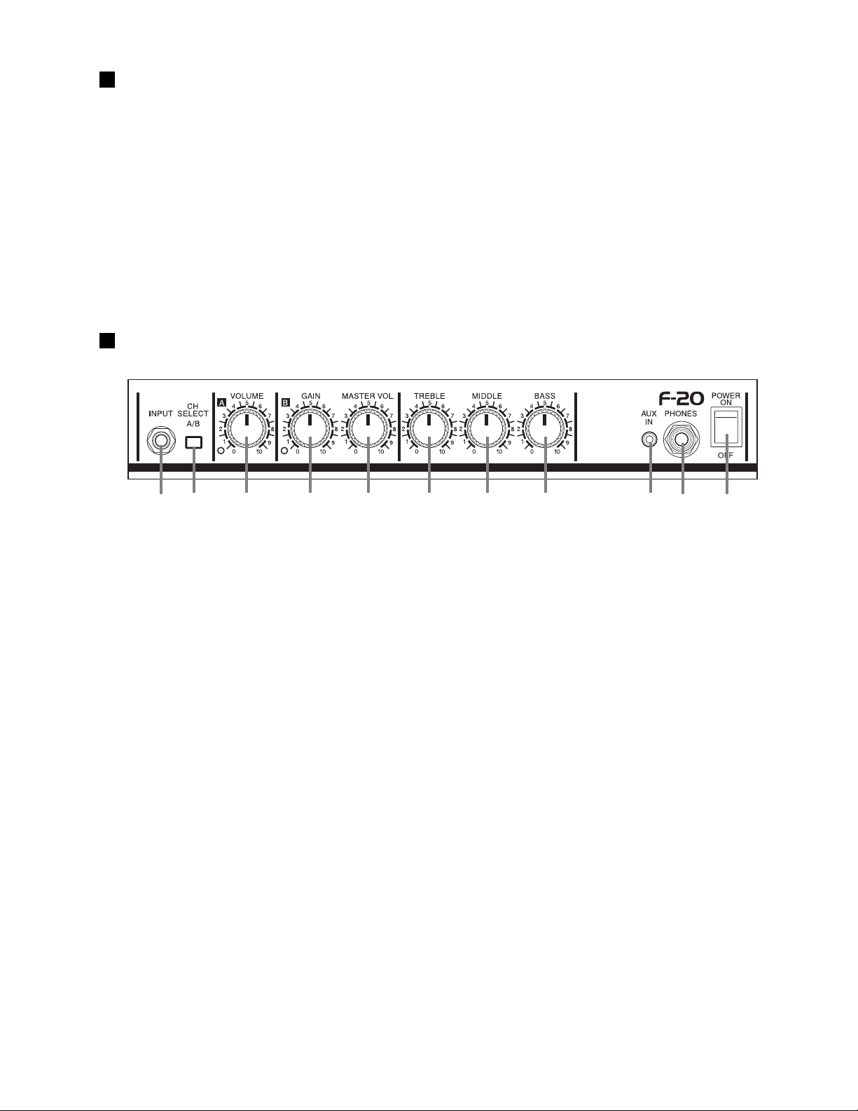
PANEL LAYOUT
F-20
INPUT
CH SELECT A/B (Channel Select Switch A/B)
A Channel
VOLUME
* No sound is produced when the VOLUME knob is
set to "0".
B Channel
GAIN
MASTER VOL.
* No sound is produced when the MASTER VOL.
knob is set to "0".
Tone Controls
TREBLE
MIDDLE
BASS
AUX IN
* Use the volume control on the audio device to
control its volume level.
PHONES
* The speaker produces no sound when a pair of
headphones is connected to this jack.
POWER
3

F-20
CIRCUIT BOARD LAYOUT
Top View
MAIN 1/2
MAIN 2/2
AC Cord
Side View
Power Transformer
MAIN 2/2
MAIN 1/2
Front View
BLOCK DIAGRAM
MAIN 1/2
OP AMP
CN1 2P
+12V
31
IC1
-12V
GAIN
VR2
OP AMP
31
INPUT
JK1
POWER SWITCH
SW1
T1
T2
U, C, S, BS
IC2
-12V
CH. A
CLEAN
VOLUME
VR1
+12V
CH. SELECT SW
SW2
MASTER
VR3
FUSE
FZ1
CN2 4P
POWER TRANSFORMER
CH. A
CLEAN
CH. B
DRIVE
+B
OP AMP
57
INDICATOR
CH. B
DRIVE
T1
G
T2
IC1
-12V
+12V
MAIN 1/2
IC1. IC2
PASSIVE TYPE
TONE CONTROL
VR4 VR5 VR6
TREBLE
POWER SUPPLY CIRCUIT
CN3 3P
MIDDLE
BASS
OP AMP
+12V
57
IC2
-12V
CN4 5P
+B
+12V
-12V
-B
MAIN 2/2
+B
14
IC3
-B
CN5 5P
POWER
AMP
V695450
JK3
T3
T4
JK2
AUX IN
4Ω Speaker
PHONES
4
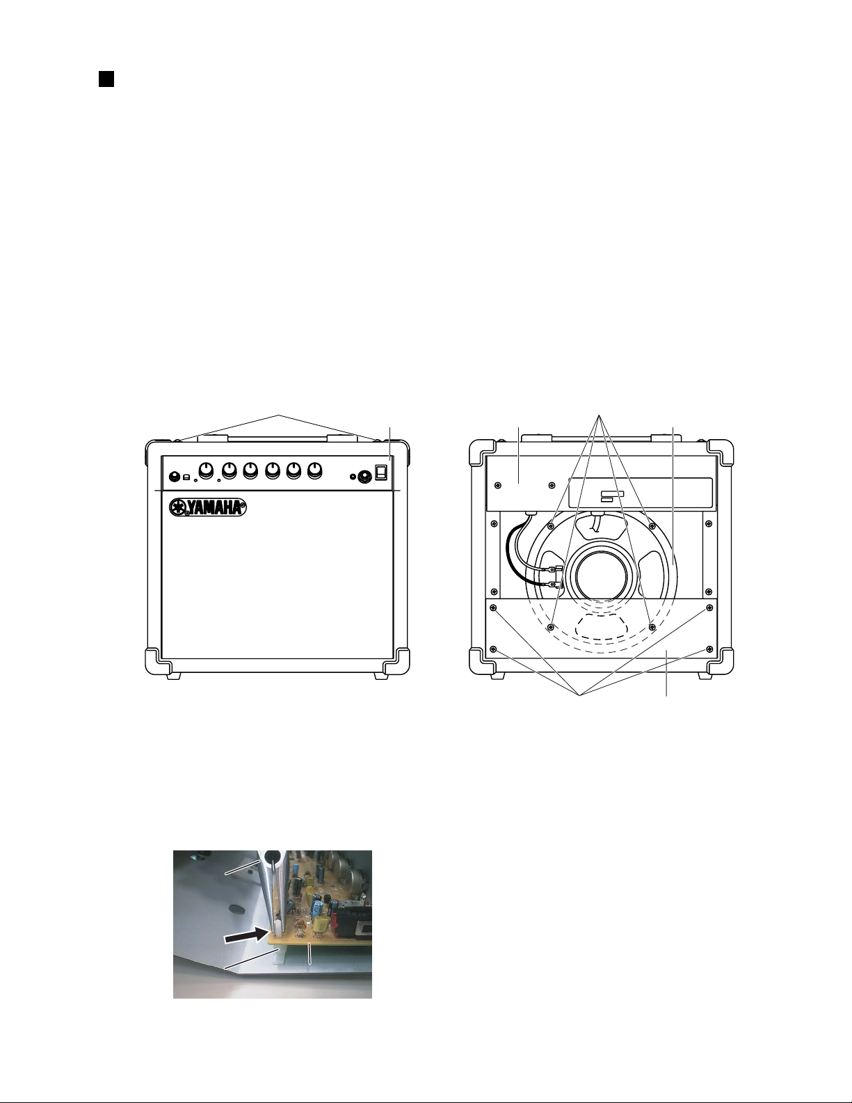
DISASSEMBLY PROCEDURE
MAIN1/2 Circuit Board
Needle Nose Plier
[P40]
1. Pre-Main Unit (Time required: about 1 min)
1-1 Remove the speaker wires.
1-2 Remove the four (4) screws marked [30]. The pre-main unit can then be removed by sliding it backward. (Fig.1)
2. Speaker (Time required: about 1 min)
2-1 Remove the four (4) screws marked [A]. The back board can then be removed. (Fig.1)
2-2 Remove the four (4) screws marked [B]. The speaker can then be removed. (Fig.1)
3. MAIN 1/2 Circuit Board (Time required: about 3 min)
3-1 Remove the pre-main unit. (See procedure 1)
3-2 Remove the six (6) knobs marked [P100] and the six (6) hexagonal nuts marked [C]. (Fig.5)
3-3 Remove the hexagonal nuts marked [A120] and the hexagonal nuts marked [A140]. (Fig.5)
3-4 Push the hooks of the spacer support (at the arrow symbol area of illustration) with a needle-nose plier to unlock.
The Main 1/2 circuit board can then be removed. (Fig.2)
F-20
[30] x 4
[30]: Truss Head Screw 4.0X25 MFZN2BL (VN347600)
Pre-Main UnitPre-Main Unit
[B]
[A] Back Board
[A]: Bind Head Tapping Screw 4.0X25 FCRM3-BL (EI340256)
[B]: Bind Head Screw 4.0X20 ZMC2BL (VB403600)
Speaker
(Fig. 1)
Needle Nose Plier
Needle Nose Plier
[P40]
[P40]
MAIN1/2 Circuit Board
MAIN1/2 Circuit Board
(Fig. 2)
5
 Loading...