

Yamaha 6MH, 6CMH, 8CMH, 8MH, E8DMH Rigging Manual
...


PREFACE
This rigging guide has been published to help Yamaha dealers set up Yamaha outboard-motors and
genuine accessories.
The information and/or materials is based on 2009 year models available at the time when this
guide has issued.
For US and Canada, the model name is expressed in the parenthesis for descriptive purposes.
In this guide, particularly important information is distinguished in the following ways,
WARNING
Failure to follow WARNING instructions could result in severe injury or death to the machine
operator, a bystander, or a person inspecting or repairing the products.
NOTICE
A NOTICE indicates special precautions that must be taken to avoid damages to the products.
Specifications and descriptions are subject to change without notice.
The PDF file is available from the service portal site maintained by Yamaha Motor Co., Ltd.
The following contracted terms are expediently used on this guide.
EXT; extension
OP; optional
P/N; part number
PTT; power trim & tilt
RC; remote control
SW; switch
IG; ignition
2009 OUTBOARD MOTOR
RIGGING GUIDE
(c) 2008 Yamaha Motor Co., Ltd.
1st edition, June 2008
All rights reserved.
Reproduction or unauthorized use
without the written permission of
Yamaha Motor Co., Ltd.
is expressly prohibited.
Produced in Japan


CONTENTS
INSTALLATION............................................................................................1-1
TOP COVER PICTOGRAPH DESCRIPTION...............................................................1-2
UNCRATING PROCEDURE (FOR TYPICAL STEEL FRAME)....................................1-3
MOUNTING THE OUTBOARD MOTOR.......................................................................1-5
MOUNTING THE REMOTE OIL TANK.......................................................................1-10
OUTBOARD MOTOR DIMENSIONS..........................................................................1-12
PROPELLERS..............................................................................................2-1
PROPELLER SPECIFICATIONS..................................................................................2-2
PROPELLER SELECTION...........................................................................................2-5
2009 PROPELLER APPLICATIONS ............................................................................2-5
WOT OPERATION RANGE TABLE ...........................................................................2-11
REMOTE CONTROLS .................................................................................3-1
REMOTE CONTROL APPLICATIONS.........................................................................3-2
REMOTE SWITCH APPLICATIONS ..........................................................................3-15
REMOTE CONTROL CABLES...................................................................................3-24
REMOTE CONTROL ATTACHMENT KIT..................................................................3-26
STEERING HOOK......................................................................................................3-28
STEERING GUIDE ATTACHMENT KIT .....................................................................3-31
CONVENTIONAL WIRE HARNESS...........................................................................3-33
DIGITAL ELECTRONIC CONTROL WIRE HARNESS...............................................3-35
TILLER HANDLES.......................................................................................4-1
6X4 MULTI-FUNCTION TILLER HANDLE ...................................................................4-2
STEERING FRICTION CONTENTS...........................................................................4-11
CONVENTIONAL GAUGE (6Y5 & 6Y7)......................................................5-1
MOUNTING THE METERS ..........................................................................................5-4
ANALOG TACHOMETER.............................................................................................5-5
DIGITAL TACHOMETER..............................................................................................5-7
SPEEDOMETER...........................................................................................................5-9
FUEL MANAGEMENT GAUGE ..................................................................................5-12
ANALOG TRIM METER..............................................................................................5-18
COOLANT PRESSURE METER ................................................................................5-19
COOLANT TEMP. METER .........................................................................................5-20
HOUR METER............................................................................................................5-26
VOLTAGE METER......................................................................................................5-28
FUEL METER .............................................................................................................5-29
CHARGE WARNING UNIT.........................................................................................5-30
WIRE HARNESSES....................................................................................................5-31
WIRING DIAGRAMS...................................................................................................5-35

CONTENTS
DIGITAL NETWORK GAUGE (6Y8)............................................................6-1
DIGITAL NETWORK GAUGE COMPATIBLE MODEL.................................................6-2
DIGITAL NETWORK GAUGE APPLICATION..............................................................6-2
DIGITAL NETWORK GAUGE DIMENSIONS...............................................................6-3
OPTIONAL EQUIPMENTS ...........................................................................................6-5
WIRE HARNESS ..........................................................................................................6-7
WIRING DIAGRAMS.....................................................................................................6-9
INITIAL GAUGE SETUP.............................................................................................6-17
TROUBLESHOOTING................................................................................................6-18
BASIC REQUIREMENTS ...........................................................................................6-19
NMEA0183 COMPATIBLE EQUIPMENTS CONNECTION........................................6-19
BATTERY.....................................................................................................7-1
RECOMMENDED BATTERY........................................................................................7-2
BATTERY CABLE LENGTH .........................................................................................7-3
BATTERY WIRING .......................................................................................................7-4
APPENDIX....................................................................................................8-1
MODEL NAME DESIGNATION ....................................................................................8-2
FUEL SYSTEM VACUUM PRESSURE STANDARD...................................................8-4
PORTABLE FUEL TANKS (TYPICAL) .........................................................................8-6
FUEL PIPES (TYPICAL)...............................................................................................8-6
PRE-DELIVERY INSPECTION (PDI) CHECKS ...........................................................8-7
CONVENTIONAL RIGGING KIT CONTENTS..............................................................8-8
DIGITAL NETWORK GAUGE RIGGING KIT CONTENTS.........................................8-11
2009 MANUFACTURING START SERIAL NUMBER.................................................8-25

INSTALLATION
TOP COVER PICTOGRAPH DESCRIPTION...........................................1-2
UNCRATING PROCEDURE (FOR TYPICAL STEEL FRAME)...............1-3
MOUNTING THE OUTBOARD MOTOR ..................................................1-5
WATER LEVEL GUIDELINE (4-STROKE ENGINES)..........................1-9
ADJUSTING TWIN MOTORS ............................................................1-10
MOUNTING THE REMOTE OIL TANK..................................................1-10
REMOTE OIL TANK DIMENSIONS...................................................1-10
NOTICE FOR MOUNTING THE REMOTE OIL TANK.......................1-11
OUTBOARD MOTOR DIMENSIONS ..................................................... 1-12
OVERALL DIMENSION ITEMS..........................................................1-12
OVERALL DIMENSIONS (2-STROKE)..............................................1-14
OVERALL DIMENSIONS (4-STROKE)..............................................1-21
CLAMP BRACKET DIMENSION ITEMS............................................1-28
CLAMP BRACKET DIMENSIONS......................................................1-29
1-1
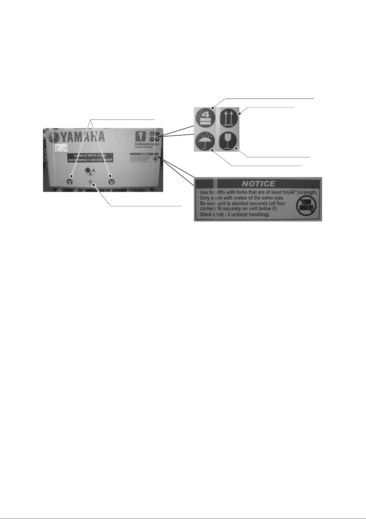
TOP COVER PICTOGRAPH DESCRIPTION
The following pictographs are important sign to handle the crate.
Read the notice and understand what pictographs mean to avoid a damage to the product when
handling, transporting and/or keeping the crate.
* Photo shows F300/F350.
Stack limit: Max. 4 units for storage
Upward indication
Lifting fork insert position
Care handling indication
Water avoidance indication
Product barycentric position
1-2
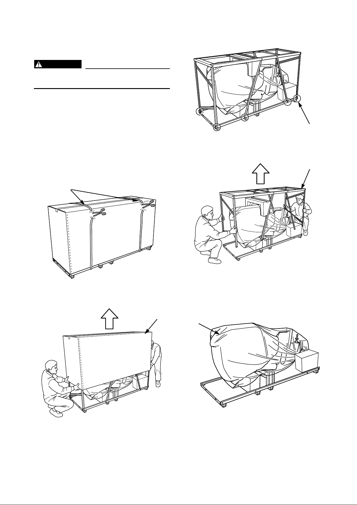
UNCRATING PROCEDURE (FOR TYPICAL STEEL FRAME)
WARNING
Wear gloves to avoid injury by sharp steel
edges while uncrating.
This is an example of the steel crate for V6
models.
For other steel crate models, refer to this procedure for uncrating the steel frame.
1. Inspect the crate for shipping damage. If a
damage has been found, consult your
Yamaha dealer.
4. Remove the bottom bolts (3).
(3)
5. Lift the top frame (4) straight up.
2. Cut the two straps (1).
(1)
3. Lift the top cover (2) straight up to remove.
(2)
(4)
6. Remove the wrapping (5), and inspect the
outboard motor for concealed damage. If
any damage is found, consult your Yamaha
dealer.
(5)
1-3
To be continued.
UNCRATING PROCEDURE
(A)
(D)
(B)
(C)
(FOR TYPICAL STEEL FRAME)
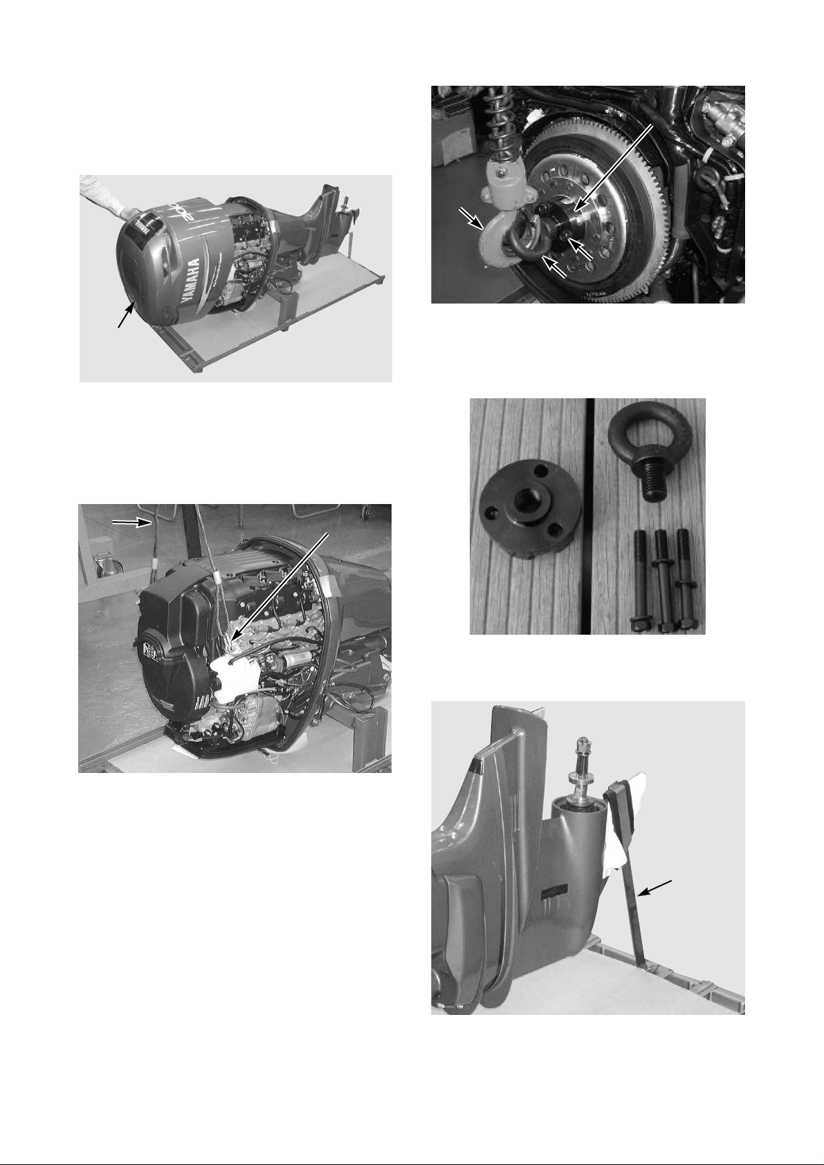
7. Remove the top cowling (6).
(6)
8. If the lifting points are covered by the flywheel cover, remove it.
9. Attach a lifting harness (7) securely to the
lifting points (8), and tighten the harness.
(A)
(A)
(D)
(D)
(B)
(B)
(C)
(C)
* F350/F300 lifting eye kit (P/N: 90890-06820)
as special service tool.
Lifting eye kit contents:
Eye bolt (C)
Eye bolt (C)
Attachment (A)
Attachment (A)
(7)
(7)
For F350/F300, install the lifting attachment (A) to the flywheel using the exclusive
3 bolts (B), insert the eye bolt (C) to the
attachment, attach a lifting harness (D) to
the eye bolt, and tighten the harness.
[Bolt (B) torque: 36 Nm, 3.6 kgf•m, 27 lb•ft]
(8)
(8)
Bolt (B)
Bolt (B)
90890-06821 (3 pcs)
90890-06821 (3 pcs)
10.Remove the skeg holder (9) if it is attached.
(9)
To be continued.
1-4
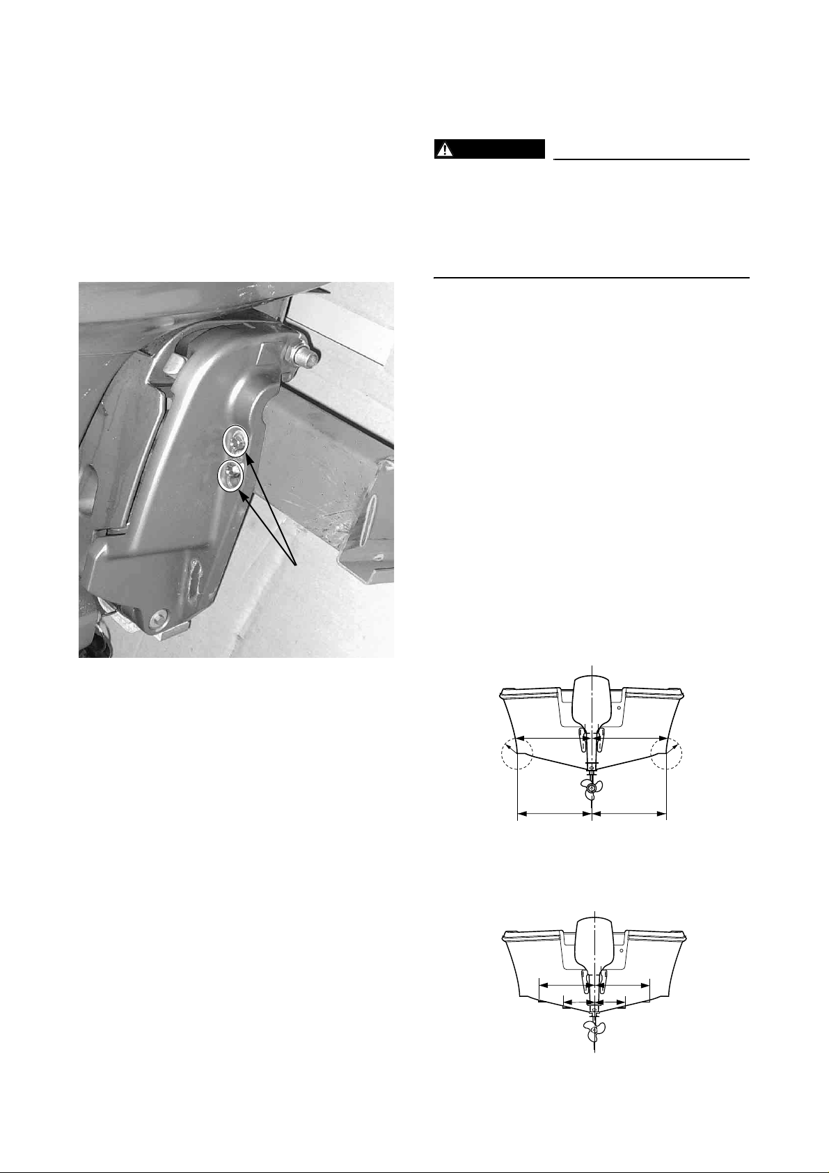
UNCRATING PROCEDURE
MOUNTING THE OUTBOARD
(FOR TYPICAL STEEL FRAME)
11. Carefully lift up the motor with the bottom
crate so that the lifting-harness does not
contact to the engine components.
Have a helper hold the frame to avoid injury
while lifting.
12. Remove the bracket bolts (10).
(10)
MOTOR
WARNING
Overpowering a boat may cause severe
instability. Never install an outboard motor
that exceeds the maximum boat horsepower rating capacity. If a boat does not
have the capacity plate, ask to the boat
manufacturer.
Proper mount of outboard motor will obtain
better engine performance, product reliability,
fuel economy, customer satisfaction, etc.
This chapter describes the brief summary of
outboard motor mount.
For the first requirement, make sure the outboard motor has clearance for full movement,
from port to starboard, as well as during tilt
operation.
For the motor dimensions, see the later pages.
1. Set an outboard motor on the vertical center
line of boat transom.
Measurement points are shown in the illustration.
No strakes hull
Make a same radius at both sides of hull, and
have another measurement points.
C/L
(a)
rr
(c)
(b)
(d)
Strakes hull
Have the measurements between port and
starboard strakes.
C/L
(a)
(c)
(b)
(d)
*C/L: Centerline of the transom.
1-5
To be continued.
MOUNTING THE OUTBOARD
MOTOR
Recheck the measurements, and verify the
boat transom vertical centerline is straight.
Measurements (a) and (b) should be the
same, and measurement (c) and (d) should be
the same.
If mounting twin motors, set the motors so
that the distance between the boat transom
center line and the motor center line should be
equal for the both motors.
C/L
(e)
(f)
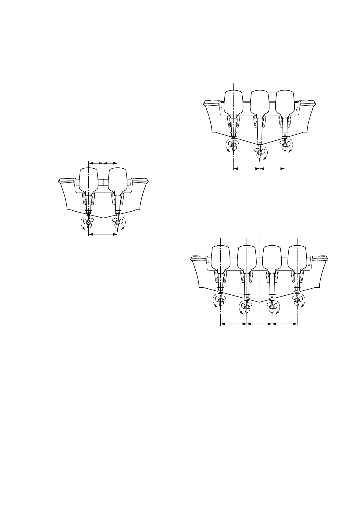
For triple motors installation, set the motors
as shown below.
If a boat has V-hull, the center motor should
use longer transom motor than outside motors.
C/L
(T1) (T1)
For quad motors installation, set the motors
as shown below.
If a boat has V-hull, inner twin motors should
use longer transom motor than outside motors.
(T1)
Measurements (e) and (f) should be the same.
Maintain a minimum distance (T1) that is the
measurement between both vertical centerlines of outboard motor.
Minimum distance (T1) is recommended on
each model, and its data is put on the dimension item.
C/L
(T1) (T1)
(T1)
To be continued.
1-6

MOUNTING THE OUTBOARD
MOTOR
2. Adjust the height of outboard motor so that
the anti-cavitation plate is positioned to the
boat transom bottom, or lowered within 25
mm (1 in.).
For planing boats, the anti-cavitation plate
should be positioned to the boat transom
bottom or slightly higher.
Single motor
* Due to combination of a boat type and an engine
type, the mount height of outboard moto r va ries.
Therefore, the complete information is impossible
to describe here.
For further information, see the instruction issued
by boat manufacturer, or ask to the manufacturer.
3. When the outboard motor mount position
has determined, mark the 4 symmetrical
mount hole positions onto the boat transom.
Make the mount holes of 13 mm (0.5 in.)
vertically on the marking points.
(0.5 in.)
0~25 mm (1 in.)
Twin motors/ Quad motors
C/L
0~25 mm
(1 in.)
(a)
Twin motors
Quad motors
0~25 mm
(1 in.)
13 mm
90
(a)
To be continued.
0~25 mm
(1 in.)
Triple motors
0~25 mm
(1 in.)
(a): Anti-cavitation plate
(a)
C/L
0~25 mm
(1 in.)
0~25 mm
(1 in.)
1-7

MOUNTING THE OUTBOARD
MOTOR
For 115 – 300 and F115 – F350, select the
transom mount bolt due to the boat transom
thickness.
4. Apply a sealant to the mount holes, and secure the motor with supplied mount hardware.
For tightening procedure, first tighten the inside nut, then the double nuts each other.
NOTICE
Make sure there is no clearance between
boat transom and motor clamp bracket.
Otherwise, the clamp bracket could break.
* The upper mount bolt is usually installed to
the 2nd hole from top.
For reference:
M8: 18 Nm, 1.8 kgf•m, 13 lb•ft
M10:36 Nm, 3.6 kgf•m, 27 lb•ft
M12:52 Nm, 5.2 kgf•m, 38 lb•ft
(a)
Boat transom
thickness (T)
55 – 65 mm
(2.17 – 2.56 in.)
65 – 75 mm
(2.56 – 2.95 in.)
75 – 95 mm
(2.95 – 3.74 in.)
95 – 115 mm
(3.74 – 4.53 in.)
* High tension bolt is recommended to F300/F350.
Mount bolt size Bolt P/N
M12 ×115 mm 90101-12M03
M12 ×130 mm 90101-12M05
M12 ×150 mm 90101-12M77
M12 ×150 mm
[High tension bolt]
M12 ×170 mm
[High tension bolt]
90101-12031
90101-12036
(b)
(c)
(d)
(b)
T
(a)
(b)
(c)
(a) Mounting bolt
(b) Small washer
(c) Large washer
(d) Nut
: Sealant
* Tighten the mounting bolts/ nuts by suitable torque
due to boat transom structure, material, design,
etc.
(b)
(d)
1-8

MOUNTING THE OUTBOARD MOTOR
WATER LEVEL GUIDELINE (4-STROKE ENGINES)
If you replaced 2-stroke engine to 4-stroke engine which has the sa me horse po wer , a boat tends to
become “stern heavy” because of heavier engine weight.
As a result, water line will rise and get close to the power head.
This effects a poor engine performance, and water could easily enter into the cylinder(s) and damage the engine.
Therefore, you should consider the water level guideline to install 4-stroke outboard motor.
Under mooring of boat with a maximum boat load, maintain the minimum height (H) shown in the
illustration between the water surface and the clamp bracket seating point.
(H)
Water surface
Minimum height between water surface and bracket seating point
Model Min. height (H)
Carbureted F2 – F60 150 mm 5.9 in
Fuel injected F40 (4-cyl) – F60 100 mm 3.9 in
F75 and above 100 mm 3.9 in
1-9
MOUNTING THE OUTBOARD
MOUNTING THE REMOTE OIL
MOTOR
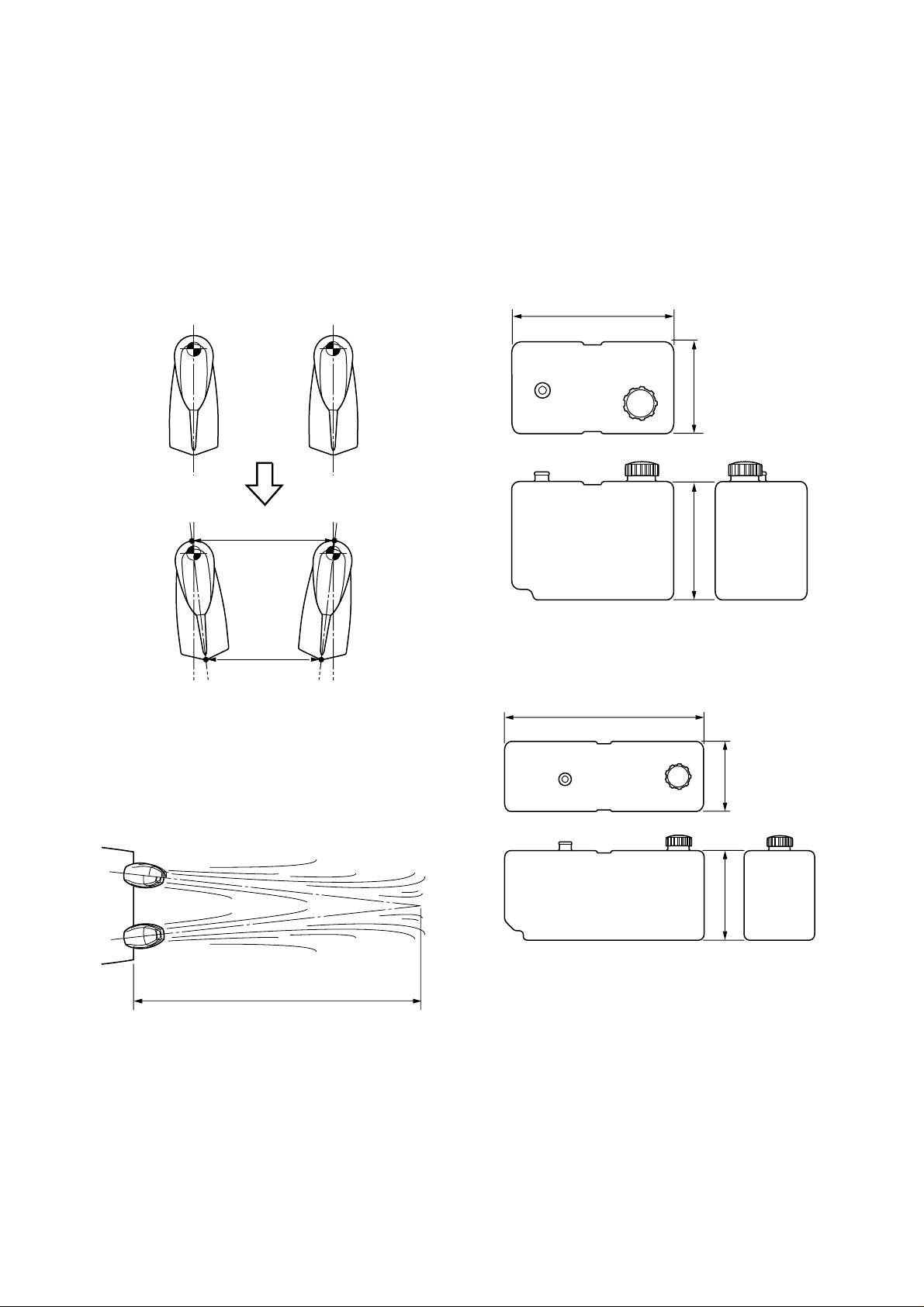
ADJUSTING TWIN MOTORS
Set the engines in the toe-out position, and
measure the distances between the two
engines at the center point of the rear (a) and
front (b) of the lower casing. The difference
between measurement (a) and measurement
(b) should not exceed 25 mm (1 in.).
(b)
TANK
The remote oil tank is required for 2-stroke V4
and V6 oil injection engines.
REMOTE OIL TANK DIMENSIONS
10.5 liters (2.8 US gallons) tank P/N: 6E5-21733-20
mm (in.)
320 (12.6)
180 (7.1)230 (9.1)
(a)
* Adjustment: (b) – (a) = Within 25 mm (1 in)
For best result, your toe-out distance should
be set so that the twin motors wake meets
approximately 7.5 – 15 m (25 – 50 ft) past the
stern of the boat.
7.5 – 15 m (25 – 50 ft)
18 liters (4.8 US gallons) tank P/N: 6E5-21733-30
mm (in.)
508 (20)
180 (7.1)
235 (9.3)
1-10

MOUNTING THE REMOTE OIL
TANK
Oil tank holder
mm (in.)
250 (9.8)
200 (7.9)
130 (5.1)
210 (8.3)
30
(1.2)
160 (6.3)
6.5 (0.26)
(1.2)
30
170 (6.7)
NOTICE FOR MOUNTING THE REMOTE OIL TANK
Follow the notifications below, for the remote
oil tank installation.
• Mount the oil tank in as dry as possible location to avoid water entering into the oil tank.
• Mount in a location that will allow service to
the filter located on the remote oil tank.
• Mount the remote oil tank lower than the
engine oil tank.
If the remote oil tank is mounted higher than
the top of the engine because of a boat type,
an optional check valve (P/N: 6R5-24408-
00) shown below is required.
173
(6.8)
112
(4.4)
40 (1.6)
200 (7.9)
25 (1.0)
Install it on the oil hose between the engine
and remote oil tank to prevent siphoning of
oil to the engine and spillage.
• Route the oil hose between the engine and
the remote oil tank without pinching and
kinking.
1-11

OUTBOARD MOTOR DIMENSIONS
OVERALL DIMENSION ITEMS
Symbol Definition and Description
L1 Horizontal distance from datum point to rearmost point of power unit
L2 Horizontal distance from datum point to forefront (depend on the model) of power unit
L3
L4 Horizontal distance from datum point to rearmost point of the lower case
L5
L6
L7
L8
L9 Horizontal forward protrusion of lower case from the datum line when PT/T is fully trimmed down
L10 Horizontal distance from datum point to bracket shaft (bolt) center
H1 Vertical distance from datum point to lowest point of motor
H2 Vertical distance from datum point to highest point of po wer head
H3 Vertical distance from cavitation plate undersurface to propeller shaft
H4 Vertical distance from datum point to cavitation plate undersurface
H5 Vertical distance from datum point to tiller handle tip when the handle is in vertical position
H6
H7 Vertical distance from datum line to protruded forefront when motor is tilted up (over-tilt position)
H8
H9 Vertical distance to the highest point of the motor when it is tilted up (over-tilt position)
H10 Vertical distance from datum point to bracket shaft (bolt) center
H11
W1 Leftward protrusion from center line of motor body when looking at the front face
W2 Distance from tiller handle tip to centerline of motor body when looking at the front face
W3 Distance from centerline to left or right edge of motor body, except for levers and handles
W4
W5 Distance from centerline to the farthest point on the body when steered to the maximum angle
W6
A1 Maximum steering angle each way (symmetrical), from centerline of motor body
A2 Tilt up angle (whole rotating range to over-tilt angle including negative trim angle)
A3 Maximum negative trim angle from the vertical line through the datum point
T1 Cente rline- to -centerline minimum distance of the motors in case of twin installation
Distance from datum point to farthest point on tiller handle, when the handle is in horizontal position (in use)
Minimum distance from transom board or its extension t o forefront of the lower case, with motor
fully trimmed down and steered to the full
Horizontal distance from datum point to rearmost point of protrusion when motor is tilted up (overtilt position)
Horizontal distance from datum point to protruded forefront when motor is tilted up (over-tilt position)
Horizontal distance from datum point to lowest point of protrusion wh en motor is tilted up ( over-tilt
position)
Vertical distance from skeg tip at H1 to the lowest point of lower unit when motor is tilted up (overtilt position)
Vertical distance from datum line to lowest point of protrusion when motor is tilted up (over-tilt
position)
Difference in the height of lower unit lowes t po int co mp a rin g th e he igh t in the sta nd ar d posit i on
and with PT/T in the fully trimmed down position.
Distance from centerline to left or right end of motor body protrusion, except for levers and handles
Distance from centerline to the farthest point on the tiller handle when steered to the maximum
angle
1-12
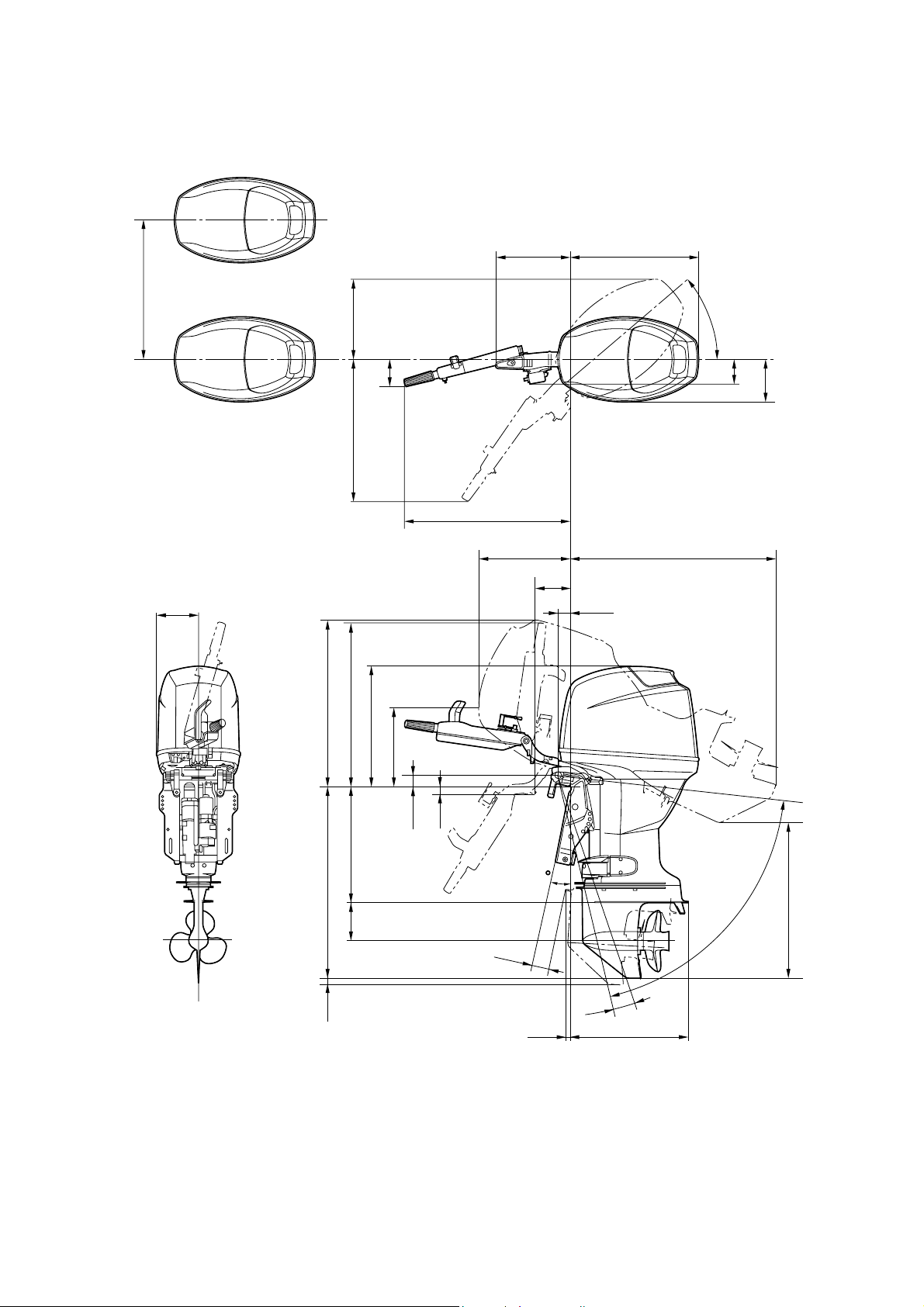
OUTBOARD MOTOR DIMENSIONS
OVERALL DIMENSION ITEMS
L
2
1
T
5
W
2
W
6
L
1
A
1
3
4
W
W
W
L
3
L
6
W
L
7
L
8
1
5
9
H
H
2
H
7
H
L
10
8
10
H
4
H
1
H
3
H
11
H
H
12
6
2
A
L
5
3
A
L
L
9
4
H
1-13

OUTBOARD MOTOR DIMENSIONS
OVERALL DIMENSIONS (2-STROKE)
Model
2CMH 3AMH
Symbol
L1 mm (in.) 275 (10.8) 311 (12.2) 344 (13.5) 344 (13.5) 363 (14.3) 346 (13.6) 393 (15.5) 405 (15.9)
L2 mm (in.) 122 (4.8) 107 (4.2) 145 (5.7) 145 (5.7) 114 (4.5) 180 (7.1) 180 (7.1) 165 (6.5)
L3 mm (in.) 328 (12.9) 317 (12.5) 333 (13.1) 333 (13.1) 439 (17.3) 372 (14.6) 479 (18.9) 473 (18.6)
L4 mm (in.) 164 (6.5) 223 (8.8) 252 (9.9) 252 (9.9) 359 (14.1) 268 (10.6) 355 (14.0) 357 (14.0)
L5 S mm (in.) 34 (1.3) 16 (0.6) 16 (0.6) 16 (0.6) 121 (4.8) 23 (0.9) 78 (3.1) 79 (3.1)
L — 16 (0.6) 24 (0.9) 24 (0.9) 126 (5.0) 23 (0.9) 104 (4.1) 78 (3.1)
Y ————————
X — — — — 126 (5.0) 23 (0.9) — 78 (3.1)
U ——————134 (5.3)—
L6 S mm (in.) 589 (23.2) 636 (25.0) 635 (25.0) 635 (25.0) 705 (27.8) 657 (25.9) 718 (28.3) 708 (27.9)
L — 760 (29.9) 758 (29.8) 758 (29.8) 826 (32.5) 782 (30.8) 831 (32.7) —
Y ————————
X — — — — 887 (34.9) 827 (32.6) — —
U ——————957 (37.7) —
L7 mm (in.) 276 (10.9) 311 (12.2) 331 (13.0) 331 (13.0) 287 (11.3) 354 (13.9) 314 (12.4) 334 (13.1)
L8 mm (in.) 142 (5.6) 156 (6.1) 148 (5.8) 148 (5.8) 154 (6.1) 207 (8.1) 263 (10.4) 165 (6.5)
L9Smm (in.)————————
L ———————4 (0.2)
Y ————————
X ———————14 (0.6)
U ————————
L10 mm (in.) 50 (2.0) 68 (2.7) 68 (2.7) 68 (2.7) 65 (2.5) 45 (1.8) 75 (3.0) 73 (2.9)
H1 S mm (in.) 614 (24.2) 654 (25.7) 653 (25.7) 653 (25.7) 682 (26.9) 685 (27.0) 705 (27.8) 706 (27.8)
L — 781 (30.7) 780 (30.7) 780 (30.7) 809 (31.9) 825 (32.5) 832 (32.8) 833 (32.8)
Y ————————
X — — — — 872 (34.3) 875 (34.4) — 975 (38.4)
U ——————974 (38.3) —
H2 mm (in.) 302 (11.9) 343 (13.5) 358 (14.1) 325 (12.8) 295 (11.6) 359 (14.1) 335 (13.2) 356 (14.0)
H3 mm (in.) 100 (3.9) 103 (4.1) 105 (4.1) 105 (4.1) 123 (4.8) 122 (4.8) 135 (5.3) 34 (1.4)
H4 S mm (in.) 417 (16.4) 441 (17.4) 444 (17.5) 444 (17.5) 436 (17.2) 442 (17.4) 440 (17.3) 441 (17.4)
L — 568 (22.4) 571 (22.5) 571 (22.5) 563 (22.2) 582 (22.9) 567 (22.3) 568 (22.4)
Y ————————
X — — — — 626 (24.6) 632 (24.9) — 710 (28.0)
U ——————709 (27.9) —
H5 mm (in.) 462 (18.2) 484 (19.1) 396 (15.6) 396 (15.6) 462 (18.2) 415 (16.3) 467 (18.4) 474 (18.7)
H6 S mm (in.) 503 (19.8) 621 (24.4) 623 (24.5) 623 (24.5) 668 (26.3) 497 (19.6) 572 (22.5) 569 (22.4)
L — 717 (28.2) 719 (28.3) 719 (28.3) 758 (29.8) 574 (22.6) 641 (25.2) 638 (25.2)
Y ————————
X — — — — 803 (31.6) 601 (23.7) — 714 (28.1)
U ——————718 (28.3) —
H7 mm (in.) 38 (1.5) 342 (13.5) 104 (4.1) 104 (4.1) 110 (4.3) 86 (3.4) 138 (5.4) —
H8 mm (in.) 12 (0.5) 9.0 (0.35) 30 (1.2) 30 (1.2) 2.0 (0.08) 51 (2.0) 19 (0.7) 24 (0.9)
H9 mm (in.) 397 (15.6) 419 (16.5) 459 (18.1) 459 (18.1) 470 (18.5) 465 (18.3) 526 (20.7) 555 (21.9)
H10 mm (in.) 27 (1.0) 30 (1.2) 30 (1.2) 30 (1.2) 32 (1.3) 26 (1.0) 34 (1.3) 34 (1.4)
H11Smm (in.)————————
L ————————
Y ————————
X ————————
U ————————
W1 mm (in.) 151 (5.9) 108 (4.3) 144 (5.7) 144 (5.7) 150 (5.9) 136 (5.4) 143 (5.6) 173 (6.8)
W2 mm (in.) 125 (4.9) 181 (7.1) 178 (7.0) 178 (7.0) 193 (7.6) 192 (7.6) 189 (7.4) —
W3 mm (in.) 89 (3.5) 105 (4.1) 134 (5.3) 134 (5.3) 137 (5.4) 129 (5.1) 143 (5.6) —
W4 mm (in.) — — — — — 158 (6.2) — 185 (7.3)
W5 mm (in.) — — — — 283 (11.1) — 280 (11.0) 280 (11.0)
W6 mm (in.) — — — — 551 (21.7) — 497 (19.6) 493 (19.4)
A1 degree 360 360 360 360 60 360 45(P)/40(S) 40
A2degree7376767681806363
A3degree———————4
T1mm (in.)————————
4ACMH
5CMH
5CSMH
6CMH
(6MH)
8CMH
(8MH)
E8DMH
EK8DMH
9.9FMH
(9.9MH)
15FMH
(15MH)
E9.9DMH
E15DMH
EK9.9DMH
EK15DMH
EK9.9JMH
EK15PMH
1-14

OUTBOARD MOTOR DIMENSIONS
OVERALL DIMENSIONS (2-STROKE)
25BMH
20DMH
Model
Symbol
L1 mm (in.) 428 (16.9) 428 (16.9) 429 (16.89) 429 (16.89) 465 (18.3) 465 (18.3) 489 (19.25) 504 (19.8)
L2 mm (in.) 0 185 (7.3) 180 (7.09) 180 (7.09) 198 (7.8) 114 (4.5) 89 (3.5) 188 (7.4)
L3 mm (in.) 508 (20.0) — 420 (16.5) — 497 (19.6) — — 493 (19.4)
L4 mm (in.) 402 (15.8) 402 (15.8) 385 (15.16) 385 (15.16) 496 (19.5) 496 (19.5) 520 (20.5) 421 (16.6)
L5 S mm (in.) 79 (3.1) 79 (3.1) 61 (2.40) 83 (3.27) 85 (3.3) 85 (3.3) — 94 (3.7)
L 106 (4.2) 106 (4.2) 83 (3.27) — 90 (3.5) 90 (3.5) 103 (4.1) 94 (3.7)
Y 117 (4.6) 117 (4.6) 83 (3.27) — — 99 (3.9) — 94 (3.7)
X 116 (4.6)—83 (3.27)—————
U ————————
L6 S mm (in.) 739 (29.1) 739 (29.1) 736 (28.98) 854 (33.62) 752 (29.6) 752 (29.6) — 784 (30.9)
L 852 (33.5) 852 (33.5) 854 (33.62) — 859 (33.8) 859 (33.8) 870 (34.2) 897 (35.3)
Y 898 (35.4) 898 (35.4) 897 (35.31) — — 895 (35.2) — 943 (37.1)
X 931 (36.7)—933 (36.73)—————
U ————————
L7 mm (in.) 337 (13.3) 337 (13.3) 405 (15.94) 405 (15.94) 387 (15.2) 375 (14.8) 356 (14.0) 427 (16.8)
L8 mm (in.) 242 (9.5) 242 (9.5) 195 (7.68) 195 (7.68) 228 (9.0) 173 (6.8) 158 (6.2) 193 (7.6)
L9Smm (in.)————————
L ————————
Y ————————
X ————————
U ————————
L10 mm (in.) 78 (3.1) 78 (3.1) 74.2 (2.9) 74.2 (2.92) 73 (2.9) 73 (2.9) 65 (2.6) 72 (2.8)
H1 S mm (in.) 703 (27.7) S:703 (27.7) 707 (27.83) 834 (32.83) 712 (28.0) 712 (28.0) — 771 (30.4)
L 830 (32.7) L:830 (32.7) 834 (32.83) — 833 (32.8) 833 (32.8) 835 (32.9) 898 (35.4)
Y 881 (34.7) Y:881 (34.7) 881 (34.68) — 872 (34.3) 874 (34.4) — 948 (37.3)
X 919 (36.2)—920 (36.22)—————
U ————————
H2 mm (in.) 365 (14.4) 365 (14.4) 439 (17.28) 439 (17.28) 446 (17.6) 428 (16.9) 426 (16.8) 444 (17.5)
H3 mm (in.) 144 (5.7) 144 (5.7) 144 (5.67) 144 (5.67) 148 (5.8) 148 (5.8) 148 (5.8) 162 (6.4)
H4 S mm (in.) 419 (16.5) 419 (16.5) 423 (16.65) 550 (21.65) 424 (16.7) 424 (16.7) — 444 (17.5)
L 546 (21.5) 546 (21.5) 550 (21.65) — 545 (21.5) 545 (21.5) 547 (21.5) 570 (22.4)
Y 597 (23.5) 597 (23.5) 597 (23.50) — 584 (23.0) 586 (23.1) — 622 (24.5)
X 635 (25.0)—636 (25.04)—————
U ————————
H5 mm (in.) 491 (19.3) — 466 (18.3) — 445 (17.5) — — 533 (21.0)
H6 S mm (in.) 586 (23.1) 586 (23.1) 621 (24.45) 701 (27.60) 584 (23.0) 584 (23.0) — 622 (24.5)
L 655 (25.8) 655 (25.8) 701 (27.60) — 648 (25.5) 648 (25.5) 651 (25.6) 691 (27.2)
Y 684 (26.9) 684 (26.9) 730 (28.74) — 668 (26.3) 670 (26.4) — 719 (28.3)
X 704 (27.7)—754 (29.68)—————
U ————————
H7 mm (in.) 186 (7.3) 186 (7.3) 118 (4.65) 118 (4.65) 278 (10.9) 224 (8.8) 244 (9.6) 127 (5.0)
H8 mm (in.) 24 (0.9) 24 (0.9) 30 (1.18) 30 (1.18) 29 (1.1) 9.0 (0.35) 8.7 (0.3) 30 (1.2)
H9 mm (in.) 584 (23.0) 584 (23.0) 596 (23.46) 596 (23.46) 657 (25.9) 647 (25.5) 661 (26.0) 695 (27.4)
H10 mm (in.) 41 (1.6) 41 (1.6) 40 (1.6) 40.3 (1.59) 44 (1.7) 44 (1.7) 42 (16.5) 45 (1.8)
H11Smm (in.)————————
L ——————22 (0.87)—
Y ————————
X ————————
U ————————
W1 mm (in.) — — 166 (6.54) 166 (6.54) — 154 (6.1) 154 (6.1) 190 (7.5)
W2 mm (in.) 206 (8.1) — 233 (9.2) — 208 (8.2) — 152 (6.0) 294 (11.6)
W3 mm (in.) 152 (6.0) 152 (6.0) 148 (5.83) 148 (5.83) 152 (6.0) — — 173 (6.8)
W4 mm (in.) 177 (7.0) — 192 (7.56) 192 (7.56) 179 (7.0) — — 205 (8.1)
W5 mm (in.) 296 (11.7) 296 (11.7) 302 (11.89) 302 (11.89) 310 (12.2) 310 (12.2) 310 (12.2) 360 (14.2)
W6 mm (in.) 528 (20.8) — 472 (18.6) 217 (8.54) 522 (20.6) — — 602 (23.7)
A1degree4040404040404045
A2degree6767686870706167
A3degree——————4 —
T1mm (in.)————————
20DMHO
(20MH)
25NWH
25NWC
25NMH
25NMHO
(25MH)
20DWO
25NW
E25BMH
25BWH
25BWC
25XMH
30HMH
E30HMH
30HWH
30HWC
EK25BMH
EK25CMH
25BW
30HW
30DMH
30DMHO
30DEHO
30DWH
30DE
30DEO
30DETO
E40GWH
E40GMH
EK40GMH
1-15

OUTBOARD MOTOR DIMENSIONS
OVERALL DIMENSIONS (2-STROKE)
Model
Symbol
L1 mm (in.) 504 (19.8) 504 (19.8) 533 (21.8) 553 (21.8) 533 (21.8) 490 (19.3) 490 (19.3) 528 (20.8)
L2 mm (in.) 188 (7.4) 188 (7.4) 118 (4.6) 118 (4.6) 118 (4.6) 257 (10.1) 178 (7.0) 142 (5.6)
L3 mm (in.) 493 (19.4) — 523 (20.6) — — 789 (31.1) — —
L4 mm (in.) 421 (16.6) 478 (18.8) 522 (20.6) 522 (20.6) 522 (20.6) 493 (19.4) 493 (19.4) 529 (20.8)
L5 S mm (in.) 94 (3.7) 94 (3.7) 65 (2.6) 65 (2.6) 91 (3.6) — — 78 (3.1)
L 94 (3.7) — 91 (3.6) 91 (3.6) — — — 77 (3.0)
Y 94 (3.7)—91 (3.6)—————
X ———————77 (3.0)
U ————————
L6 S mm (in.) 784 (30.9) 797 (31.4) 826 (32.5) 826 (32.5) — 798 (31.4) 798 (31.4) 822 (32.4)
L 897 (35.3) 910 (35.8) 940 (37.0) 940 (37.0) 935 (36.8) 910 (35.8) 910 (35.8) 937 (36.9)
Y 943 (37.1)—1,043 (41.1)—————
X — — — — 1,020 (40.2) — — 1,040 (40.9)
U ————————
L7 mm (in.) 427 (16.8) 427 (16.8) 397 (15.6) 397 (15.6) 391 (15.4) 433 (17.0) 401 (15.8) 387 (15.2)
L8 mm (in.) 193 (7.6) 193 (7.6) 294 (11.6) — — 273 (10.7) 179 (7.0) 153 (6.0)
L9 S mm (in.) — — 3 (0.1) 3 (0.1) — — — –11 (–0.43)
L — — 8 (0.3) 8 (0.3) 8 (0.3) — — 10 (0.4)
Y ——16 (0.6)—————
X ————16 (0.6)———
U ————————
L10 mm (in.) 72 (2.8) 72 (2.8) 65 (2.6) 65 (2.6) 65 (2.6) 72 (2.8) 72 (2.8) 63 (2.5)
H1 S mm (in.) 771 (30.4) 764 (30.1) 767 (30.2) 767 (30.2) — 751 (29.6) 751 (29.6) 753 (29.6)
L 898 (35.4) — 893 (35.2) 893 (35.2) 893 (35.2) 878 (34.6) 878 (34.6) 880 (34.6)
Y 948 (37.3)—1,007 (39.6)—————
X — — — — 1,007 (39.6) — — 994 (39.1)
U ————————
H2 mm (in.) 444 (17.5) 444 (17.5) 471 (18.5) 471 (18.5) 471 (18.5) 472 (18.6) 441 (17.4) 439 (17.3)
H3 mm (in.) 162 (6.4) 175 (6.9) 175 (6.9) 175 (6.9) 175 (6.9) 175 (6.9) 175 (6.9) 175 (6.9)
H4 S mm (in.) 444 (17.5) 421 (16.6) 424 (16.7) 424 (16.7) — 408 (16.1) 408 (16.1) 410 (16.1)
L 570 (22.4) — 550 (21.7) 550 (21.7) 550 (21.7) 535 (21.1) 535 (21.1) 537 (21.1)
Y 622 (24.5)—649 (25.6)—————
X — — — — 649 (25.6) — — 651 (25.6)
U ————————
H5 mm (in.) 533 (21.0) 533 (21.0) — — 532 (20.9) 731 (28.8) — —
H6 S mm (in.) 622 (24.5) 614 (24.2) 626 (24.6) 626 (24.6) — 579 (22.8) 579 (22.8) 635 (25.0)
L 691 (27.2) — 697 (27.4) 697 (27.4) 637 (25.1) 646 (25.4) 646 (25.4) 709 (27.9)
Y 719 (28.3)—753 (29.6)—————
X — — — — 709 (27.9) — — 775 (30.5)
U ————————
H7 mm (in.) 127 (5.0) 127 (5.0) 159 (6.3) 159 (6.3) 176 (6.9) 201 (7.9) 217 (8.5) 222 (8.7)
H8 mm (in.) 30 (1.2) 30 (1.2) 38 (1.5) — — 55 (2.2) 17 (0.7) 0.0 (0.00)
H9 mm (in.) 695 (27.4) 695 (27.4) 702 (27.6) 702 (27.6) 706 (27.8) 683 (26.9) 671 (26.4) 688 (27.1)
H10 mm (in.) 45 (1.8) 45 (1.8) 43 (1.69) 43 (1.69) 43 (1.69) 44 (1.7) 44 (1.7) 44 (1.7)
H11 S mm (in.) — — 25 (0.98) 25 (0.98) — — — 20 (0.8)
L — — 24 (0.94) 24 (0.94) 24 (0.94) — — 19 (0.7)
Y ————————
X ————55 (2.2)———
U ————————
W1 mm (in.) 190 (7.5) 190 (7.5) 182 (7.2) 182 (7.2) 182 (7.2) — 180 (7.1) 180 (7.1)
W2 mm (in.) 294 (11.6) — 220.5 (8.7) — — 124 (4.9) — —
W3 mm (in.) 173 (6.8) 173 (6.8) 182 (7.2) 182 (7.2) 182 (7.2) 175 (6.9) 175 (6.9) 175 (6.9)
W4mm (in.)205 (8.1)205 (8.1)————180 (7.1)180 (7.1)
W5 mm (in.) 360 (14.2) 360 (14.2) 369 (14.5) 369 (14.5) 369 (14.5) 340 (13.4) 340 (13.4) 340 (13.4)
W6 mm (in.) 602 (23.7) 602 (23.7) 592 (23.3) — — 641 (25.2) — —
A1degree4545454545404040
A2degree6767646461626265
A3 degree — — — — 4 — — 4
T1mm (in.)————————
40JMH
E40JMH
40JWH
E40JWH
EK40JMH
E40JW
40XMH
E40XMH
40XWH
E40XWH
40XW
E40XW
40XWT
E40XWT
40VMHO
50HMHO
40VE
40VEO
40VETO
40YETO
50HEDO
50HET
50HETO
(50TR)
1-16

OUTBOARD MOTOR DIMENSIONS
OVERALL DIMENSIONS (2-STROKE)
Model
Symbol
L1 mm (in.) 528 (20.8) 487 (19.2) 531 (20.9) 516 (20.3) 516 (20.3) 545 (21.5) 532 (20.9) 532 (20.9)
L2 mm (in.) 221 (8.7) 298 (11.7) 159 (6.3) 174 (6.9) 174 (6.9) 180 (7.1) 269 (10.6) 269 (10.6)
L3 mm (in.) 753 (29.6) 680 (26.8) — — — 790 (31.1) 651 (25.6) 651 (25.6)
L4 mm (in.) 529 (20.8) 487 (19.2) 531 (20.9) 516 (20.3) 516 (20.3) 547 (21.5) 546 (21.5) 546 (21.5)
L5 S mm (in.) — 54 (2.1) 87 (3.4) — — — 97 (3.8) —
L 77 (3.0) 71 (2.8) — 90 (3.5) 90 (3.5) 88 (3.5) 99 (3.9) 99 (3.9)
Y ————————
X————79 (3.1)85 (3.3)——
U ————————
L6 S mm (in.) — 827 (32.6) 818 (32.2) — — — 913 (35.9) —
L 937 (36.9) 932 (36.7) — 919 (36.2) 919 (36.2) 968 (38.1) 1,020 (40.2) 1,020 (40.2)
Y ————————
X — — — — 1,033 (40.7) 1,080 (42.5) — —
U ————————
L7 mm (in.) 418 (16.5) 437 (17.2) 392 (15.4) 400 (15.7) 400 (15.7) — 457 (18.0) 457 (18.0)
L8 mm (in.) 246 (9.7) 280 (11.0) 154 (6.1) 164 (6.5) 164 (6.5) 164 (6.5) 256 (10.1) 256 (10.1)
L9Smm (in.)————————
L 10 (0.4) — — — 14 (0.6) — — —
Y ————————
X ————————
U ————————
L10 mm (in.) 63 (2.5) 77 (3.0) 67 (2.6) 67 (2.6) 67 (2.6) 67 (2.6) 67 (2.6) 67 (2.6)
H1 S mm (in.) — 809 (31.9) 758 (29.8) — — — 831 (32.7) —
L 880 (34.6) 931 (36.7) — 879 (34.6) 879 (34.6) 901 (35.5) 954 (37.6) 954 (37.6)
Y ————————
X — — — — 1,006 (39.6) 1,028 (40.5) — —
U ————————
H2 mm (in.) 470 (18.5) 449 (17.7) 424 (16.7) 424 (16.7) 424 (16.7) 520 (20.5) 528 (20.8) 528 (20.8)
H3 mm (in.) 175 (6.9) 191 (7.5) 191 (7.5) 191 (7.5) 191 (7.5) 191 (7.5) 191 (7.5) 191 (7.5)
H4 S mm (in.) — 451 (17.8) 399 (15.7) — — — 450 (17.7) —
L 537 (21.1) 572 (22.5) — 520 (20.5) 520 (20.5) 520 (20.5) 538 (21.2) 538 (21.2)
Y ————————
X — — — — 647 (25.5) 647 (25.5) — —
U ————————
H5 mm (in.) 728 (28.7) 568 (22.4) ————753 (29.6) 753 (29.6)
H6 S mm (in.) — 591 (23.3) 636 (25.0) — — — 670 (26.4) —
L 709 (27.9) 652 (25.7) — 689 (27.1) 689 (27.1) 698 (27.5) 722 (28.4) 722 (28.4)
Y ————————
X — — — — 760 (29.9) 764 (30.1) — —
U ————————
H7 mm (in.) 204 (8.0) 171 (6.7) 158 (6.2) 147 (5.8) 147 (5.8) — 216 (8.5) 216 (8.5)
H8 mm (in.) 43 (1.7) 93 (3.7) 12 (0.5) 25 (1.0) 25 (1.0) 23 (0.9) 81 (3.2) 81 (3.2)
H9 mm (in.) 696 (27.4) 684 (26.9) 695 (27.4) 682 (26.9) 682 (26.9) 743 (29.3) 722 (28.4) 722 (28.4)
H10 mm (in.) 44 (1.7) 42 (1.7) 47 (1.9) 47 (1.9) 47 (1.9) 47 (1.9) 46 (1.8) 46 (1.8)
H11 S mm (in.) — 22 (0.9) 24 (0.9) 24 (0.9) 24 (0.9) — 27 (1.1) —
L 19 (0.7)21 (0.8)————27 (1.1)27 (1.1)
Y ————————
X ————————
U ————————
W1 mm (in.) 180 (7.1) — 166 (6.5) 166 (6.5) 166 (6.5) 211 (8.3) — —
W2mm (in.)124 (4.9)159 (6.3)————159 (6.3)—
W3 mm (in.) 175 (6.9) 165 (6.5) — — 166 (6.5) 187 (7.4) 182 (7.2) 182 (7.2)
W4mm (in.)180 (7.1)———————
W5 mm (in.) 340 (13.4) 268 (10.6) 271 (10.7) 271 (10.7) 271 (10.7) 331 (13.0) 322 (12.7) 322 (12.7)
W6 mm (in.) 641 (25.2) 507 (20.0) ————553 (21.8) —
A1degree4030303030303535
A2degree6564686868676767
A3 degree 4 — — — 4 — 2.8 2.8
T1mm (in.)————————
40VMHD
40VWHDO
40VWHTO
50HMHD
50HWHD
50HWHDO
50HWHTO
E48CMH
E55CMH
55BED
S-transom
55BED
L-transom
55BET 55DEHD
E60HMHD
E60HWHD
E60HWD
1-17

OUTBOARD MOTOR DIMENSIONS
OVERALL DIMENSIONS (2-STROKE)
Model
Symbol
L1 mm (in.) 547 (21.5) 532 (20.9) 547 (21.5) 532 (20.9) 532 (20.9) 545 (21.5) 545 (21.5) 545 (21.5)
L2 mm (in.) 151 (5.9) 166 (6.5) 151 (5.9) 166 (6.5) 267 (10.5) 180 (7.1) 180 (7.1) 180 (7.1)
L3 mm (in.) — — — — 798 (31.4) 790 (31.1) — —
L4 mm (in.) 562 (22.1) 547 (21.5) 562 (22.1) 547 (21.5) 547 (21.5) 547 (21.5) 547 (21.5) 547 (21.5)
L5S mm (in.)113 (4.4)—113 (4.4)—————
L — 91 (3.6) — 91 (3.6) 91 (3.6) 88 (3.5) 88 (3.5) 88 (3.5)
Y —————85 (3.3)——
X — — — 80 (3.1) 80 (3.1) 85 (3.3) 80 (3.1) 80 (3.1)
U ————————
L6Smm (in.)868 (34.2)—868 (34.2)—————
L — 968 (38.1) — 968 (38.1) 968 (38.1) 968 (38.1) 968 (38.1) 968 (38.1)
Y — — — — — 1,015 (40.0) — —
X — — — 1,081 (42.6) 1,081 (42.6) 1,080 (42.5) 1,080 (42.5) 1,080 (42.5)
U ————————
L7 mm (in.) 403 (15.9) 411 (16.2) 403 (15.9) 411 (16.2) 411 (16.2) 459 (18.1) 459 (18.1) 459 (18.1)
L8 mm (in.) 206 (8.1) 214 (8.4) 206 (8.1) 214 (8.4) 271 (10.7) 164 (6.5) 164 (6.5) 164 (6.5)
L9Smm (in.)——0.0 (0.00)—————
L — — — 14 (0.6) 14 (0.6) — — 14 (0.6)
Y ————————
X — — — 31 (1.2) 31 (1.2) — — 23 (0.9)
U ————————
L10 mm (in.) 67 (2.6) 67 (2.6) 67 (2.6) 67 (2.6) 67 (2.6) 67 (2.6) 67 (2.6) 67 (2.6)
H1Smm (in.)780 (30.7)—780 (30.7)—————
L — 901 (35.5) — 901 (35.5) 901 (35.5) 901 (35.5) 901 (35.5) 901 (35.5)
Y — — — — — 952 (37.5) — —
X — — — 1,028 (40.5) 1,028 (40.5) 1,028 (40.5) 1,028 (40.5) 1,028 (40.5)
U ————————
H2 mm (in.) 472 (18.6) 472 (18.6) 472 (18.6) 472 (18.6) 472 (18.6) 520 (20.5) 520 (20.5) 520 (20.5)
H3 mm (in.) 191 (7.5) 191 (7.5) 191 (7.5) 191 (7.5) 191 (7.5) 191 (7.5) 191 (7.5) 191 (7.5)
H4Smm (in.)400 (15.7)—400 (15.7)—————
L — 520 (20.5) — 520 (20.5) 520 (20.5) 520 (20.5) 520 (20.5) 520 (20.5)
Y — — — — — 571 (22.5) — —
X — — — 648 (25.5) 648 (25.5) 647 (25.5) 647 (25.5) 647 (25.5)
U ————————
H5 mm (in.) — — — — 706 (27.8) — — —
H6Smm (in.)645 (25.4)—645 (25.4)—————
L — 696 (27.4) — 696 (27.4) 696 (27.4) 698 (27.5) 698 (27.5) 698 (27.5)
Y — — — — — 729 (28.7) — —
X — — — 764 (30.1) 764 (30.1) 764 (30.1) 764 (30.1) 764 (30.1)
U ————————
H7 mm (in.) 262 (10.3) 249 (9.8) 262 (10.3) 249 (9.8) 249 (9.8) 199 (7.8) 199 (7.8) 199 (7.8)
H8 mm (in.) –24 (–0.94) –11 (–0.43) –24 (–0.94) –11 (–0.43) 70 (2.8) 23 (0.9) 23 (0.9) 23 (0.9)
H9 mm (in.) 719 (28.3) 706 (27.8) 719 (28.3) 706 (27.8) 731 (28.8) 743 (29.3) 743 (29.3) 743 (29.3)
H10 mm (in.) 47 (1.9) 47 (1.9) 47 (1.9) 47 (1.9) 47 (1.9) 47 (1.9) 47 (1.9) 47 (1.9)
H11Smm (in.)——0.0 (0.00)—————
L — — — 28 (1.1) 27 (1.1) — — 27 (1.1)
Y ————————
X — — — 27 (1.1) 27 (1.1) — — 27 (1.1)
U ————————
W1 mm (in.) 182 (7.2) 182 (7.2) 182 (7.2) 182 (7.2) — 211 (8.3) 187 (7.4) 187 (7.4)
W2 mm (in.) — — — — 94 (3.7) — — —
W3 mm (in.) — — — — 181 (7.1) 187 (7.4) 187 (7.4) 187 (7.4)
W4 mm (in.) — — — — 179 (7.0) — — —
W5 mm (in.) 321 (12.6) 321 (12.6) 321 (12.6) 321 (12.6) 321 (12.6) 331 (13.0) 331 (13.0) 331 (13.0)
W6 mm (in.) — — — — 583 (23.0) — — —
A1degree3535353535303030
A2degree6367636762676767
A3 degree 0 4 0 4 4 — — 4
T1 mm (in.) — — — — — 600 (23.6) 600 (23.6) 600 (23.6)
60FED
60FEDO
S-transom
60FED
60FEDO
L-transom
60FETO
70BETO
(70TR)
S-transom
60FET
60FETO
70BETO
(70TR)
L/X-transom
70BEHTO
55DEHD
75AEHD
85AEHD
75AED
85AED
75AET
85AET
1-18

OUTBOARD MOTOR DIMENSIONS
OVERALL DIMENSIONS (2-STROKE)
Model
Symbol
L1 mm (in.) 545 (21.5) 545 (21.5) 539 (21.2) 539 (21.2) 539 (21.2) 542 (21.3) 554 (21.8) 543 (21.4)
L2 mm (in.) 270 (10.6) 180 (7.1) 325 (12.8) 213 (8.4) 213 (8.4) 188 (7.4) 176 (6.9) 188 (7.4)
L3 mm (in.)652 (25.7)—845 (33.3)—————
L4 mm (in.) 547 (21.5) 547 (21.5) 616 (24.3) 616 (24.3) 616 (24.3) 616 (24.3) 632 (24.9) 634 (25.0)
L5S mm (in.)————————
L 81 (3.2) 88 (3.5) 80 (3.1) 80 (3.1) 80 (3.1) 70 (2.8) 70 (2.8) 49 (1.9)
Y 80 (3.1)—75 (3.0)—————
X 70 (2.8) 80 (3.1) 85 (3.3) 85 (3.3) 85 (3.3) 61 (2.4) 61 (2.4) 62 (2.4)
U ————————
L6Smm (in.)————————
L 966 (38.0) 968 (38.1) 1,005 (39.6) 1,005 (39.6) 1,005 (39.6) 1,007 (39.6) 1,007 (39.6) 1,030 (40.6)
Y 1,011 (39.8)—1,055 (41.5)—————
X 1,078 (42.4) 1,080 (42.5) 1,120 (44.1) 1,120 (44.1) 1,120 (44.1) 1,124 (44.3) 1,124 (44.3) 1,144 (45.0)
U ————————
L7 mm (in.) 542 (21.3) 457 (18.0) 570 (22.4) 482 (19.0) 482 (19.0) 468 (18.4) 463 (18.2) 569 (22.4)
L8 mm (in.) 256 (10.1) 164 (6.5) 270 (10.6) 214 (8.4) 215 (8.5) 173 (6.8) 159 (6.3) 173 (6.8)
L9Smm (in.)————————
L — 14 (0.6) — — 12 (0.5) 44 (1.7) 31 (1.2) 54 (2.1)
Y ————————
X — 31 (1.2) — — 12 (0.5) 53 (2.1) 40 (1.6) 62 (2.4)
U ————————
L10 mm (in.) 68 (2.7) 67 (2.6) 64 (2.5) 64 (2.5) 64 (2.5) 74 (2.9) 74 (2.9) 74 (2.9)
H1Smm (in.)————————
L 902 (35.5) 901 (35.5) 929 (36.6) 929 (36.6) 929 (36.6) 928 (36.5) 928 (36.5) 946 (37.2)
Y 953 (37.5)—982 (38.7)—————
X 1,029 (40.5) 1,028 (40.5) 1,056 (41.6) 1,056 (41.6) 1,056 (41.6) 1,054 (41.5) 1,054 (41.5) 1,072 (42.2)
U ————————
H2 mm (in.) 590 (23.2) 512 (20.2) 631 (24.8) 508 (20.0) 508 (20.0) 544 (21.4) 544 (21.4) 631 (24.8)
H3 mm (in.) 191 (7.5) 191 (7.5) 190 (7.5) 190 (7.5) 190 (7.5) 191 (7.5) 191 (7.5) 210 (8.3)
H4Smm (in.)————————
L 521 (20.5) 520 (20.5) 515 (20.3) 515 (20.3) 515 (20.3) 515 (20.3) 515 (20.3) 516 (20.3)
Y 572 (22.5)—568 (22.4)—————
X 648 (25.5) 647 (25.5) 642 (25.3) 642 (25.3) 642 (25.3) 642 (25.3) 642 (25.3) 642 (25.3)
U ————————
H5mm (in.)555 (21.9)—695 (27.4)—————
H6Smm (in.)————————
L 698(27.5) 698 (27.5) 735 (28.9) 735 (28.9) 735 (28.9) 764 (30.1) 764 (30.1) 762 (30.0)
Y 725 (28.5)—765 (30.1)—————
X 766 (30.2) 764 (30.1) 810 (31.9) 810 (31.9) 810 (31.9) 839 (33.0) 839 (33.0) 837 (33.0)
U ————————
H7 mm (in.) 253 (10.0) 226 (8.9) 150 (5.9) 150 (5.9) 150 (5.9) 180 (7.1) 191 (7.5) 205 (8.1)
H8 mm (in.) 84 (3.3) 23 (0.9) 155 (6.1) 53 (2.1) 55 (2.2) 26 (1.0) 15 (0.6) 26 (1.0)
H9 mm (in.) 778 (30.6) 730 (28.7) 780 (30.7) 730 (28.7) 730 (28.7) 730 (28.7) 741 (29.2) 788 (31.0)
H10 mm (in.) 46 (1.8) 47 (1.9) 45 (1.8) 45 (1.8) 45 (1.8) 45 (1.8) 46 (1.8) 45.4 (1.8)
H11Smm (in.)————————
L — 27 (1.1) — — — 30 (1.2) 30 (1.2) 31 (1.2)
Y ————————
X — 27 (1.1) — — — 30 (1.2) 30 (1.2) 31 (1.2)
U ————————
W1 mm (in.) — 187 (7.4) 300 (11.8) 297 (11.7) 300 (11.8) 291 (11.5) 291 (11.5) 301 (11.9)
W2mm (in.)159 (6.3)—210 (8.3)—————
W3 mm (in.) 187 (7.4) 187 (7.4) 300 (11.8) 297 (11.7) 300 (11.8) 291 (11.5) 291 (11.5) —
W4mm (in.)——300 (11.8)—————
W5 mm (in.) 331 (13.0) 331 (13.0) 424 (16.7) 422 (16.6) 424 (16.7) 409 (16.1) 409 (16.1) 426 (16.8)
W6mm (in.)506 (19.9)—705 (27.8)—————
A1degree3030353535353535
A2degree6767666670707070
A3degree—4——4444
T1 mm (in.) 600 (23.6) 600 (23.6) 660 (26.0) 660 (26.0) 660 (26.0) 660 (26.0) 660 (26.0) 660 (26.0)
E60JMHD
E65AMHD
E75BMHD
75CETO
90AETO
(90TR)
E115AMH
E115AWH
E115AE
115BE
E115AET
115BET
140BET
115CETO
(115TR)
130BETO
150AET
L150AET
200AET
L200AET
1-19
OUTBOARD MOTOR DIMENSIONS
OVERALL DIMENSIONS (2-STROKE)
Model
Symbol
L1 mm (in.) 550 (21.7) 557 (21.9) 613 (24.1) 613 (24.1) 566 (22.3) 663 (26.1)
L2 mm (in.) 179 (17.0) 179 (7.0) 180 (7.1) 180 (7.1) 181 (7.1) 202 (8.0)
L3 mm (in.)——————
L4 mm (in.) 647 (25.5) 647 (25.5) 646 (25.4) 646 (25.4) 673 (26.5) 715 (28.1)
L5S mm (in.)——————
L 61 (2.4) 61 (2.4) 53 (2.1) 53 (2.1) — 87 (3.4)
Y ——————
X 80 (3.1) — 69 (2.7) — 69 (2.7) —
U————89 (3.5)—
L6Smm (in.)——————
L 1,036 (40.8) 1,036 (40.8) 1,034 (40.7) 1,034 (40.7) — 1,033 (40.7)
Y ——————
X 1,152 (45.4) — 1,150 (45.3) — 1,155 (45.5) —
U — — — — 1,271 (50.0) —
L7 mm (in.) 587 (23.1) 587 (23.1) 574 (22.6) 574 (22.6) 631 (24.8) 633 (24.9)
L8 mm (in.) 159 (6.3) 159 (6.3) 168 (6.6) 168 (6.6) 185 (7.3) 241 (9.5)
L9Smm (in.)——————
L 41 (1.6) 41 (1.6) 42 (1.7) 42 (1.7) — 80 (3.1)
Y ——————
X 50 (2.1) — 50 (2.0) — 52 (2.0) —
U————58 (2.3)—
L10 mm (in.) 74 (2.9) 74 (2.9) 74 (2.9) 74 (2.9) 74 (2.9) 74 (2.9)
H1Smm (in.)——————
L 946 (37.2) 946 (37.2) 947 (37.3) 947 (37.3) — 932 (36.7)
Y ——————
X 1,072 (42.2) — 1,074 (42.3) — 1,077 (42.4) —
U — — — — 1,203 (47.4) —
H2 mm (in.) 670 (26.4) 691 (27.2) 708 (27.9) 746 (27.9) 710 (28.0) 783 (30.8)
H3 mm (in.) 210 (8.3) 210 (8.3) 211 (8.3) 211 (8.3) 216 (8.5) 216 (8.5)
H4Smm (in.)——————
L 516 (20.3) 516 (20.3) 516 (20.3) 516 (20.3) — 493 (19.4)
Y ——————
X 642 (25.3) — 643 (25.3) — 642 (25.3) —
U — — — — 768 (30.2) —
H5mm (in.)——————
H6Smm (in.)——————
L 773 (30.4) 773 (30.4) 774 (30.5) 774 (30.5) — 716 (28.2)
Y ——————
X 849 (33.4) — 850 (33.5) — 846 (33.3) —
U — — — — 923 (36.3) —
H7 mm (in.) 241 (9.5) 241 (9.5) 308 (12.1) 308 (12.1) 242 (9.5) 419 (16.5)
H8 mm (in.) 15 (0.6) 15 (0.6) 14 (0.6) 14 (0.6) 21 (0.8) 20 (0.8)
H9 mm (in.) 791 (31.1) 864 (34.0) 835 (32.9) 945 (37.2) 818 (32.2) 964 (38.0)
H10 mm (in.) 46 (1.8) 46 (1.8) 44 (1.7) 44 (1.7) 45 (1.8) 44 (1.7)
H11Smm (in.)——————
L 33 (1.3) 33 (1.3) 32 (1.3) 32 (1.3) — 35 (1.4)
Y ——————
X 33 (1.3) 33 (1.3) 32 (1.3) — 25 (1.0) —
U————25 (1.0)—
W1 mm (in.) 290 (11.4) 290 (11.4) 277 (10.9) 277 (10.9) 281 (11.1) 284 (11.2)
W2mm (in.)——————
W3 mm (in.) 290 (11.4) 290 (11.4) ————
W4mm (in.)——————
W5 mm (in.) 406 (16.0) 406 (16.0) 396 (15.6) 396 (15.6) 420 (16.5) 441 (17.4)
W6mm (in.)——————
A1degree353532323235
A2degree707070707066
A3degree444434
T1 mm (in.) 660 (26.0) — 660 (26.0) — 660 (26.0) —
150FETO
(150TR)
175DETO
200FETO
L200FETO
225DET
150GETO
(V150TR)
200GETO
Z150PETO
(Z150TR)
Z175GETO
(Z175TR)
Z200NETO
(Z200TR)
LZ200NETO
(LZ200TR)
Z150QETO
(VZ150TR)
Z175HETO
(VZ175TR)
Z200PETO
(VZ200TR)
250GETO
L250GETO
Z200RETO
(VZ200RTR)
Z225HETO
(VZ225HTR)
Z250FETO
(VZ250FTR)
Z300BETO
(VZ300BTR)
1-20

OUTBOARD MOTOR DIMENSIONS
OVERALL DIMENSIONS (4-STROKE)
Model
Symbol
L1 mm (in.) 315 (12.4) 375 (14.8) 430 (16.9) 430 (16.9) 430 (16.9) 430 (16.9) 430 (16.9) 430 (16.9)
L2 mm (in.) 93 (3.7) 141 (5.6) 122 (4.8) 122 (4.8) 122 (4.8) 122 (4.8) 122 (4.8) 122 (4.8)
L3 mm (in.) 309 (12.2) 342 (13.5) 608 (23.9) 498 (19.6) 608 (23.9) — 608 (23.9) —
L4 mm (in.) 215 (8.5) 259 (10.2) 355 (14.0) 355 (14.0) 367 (14.4) 367 (14.4) 367 (14.4) 367 (14.4)
L5 S mm (in.) 57 (2.2) 71 (2.8) 72 (2.8) 72 (2.8) — — — —
L 57 (2.2) 92 (3.6) 99 (3.9) 99 (3.9) 99 (3.9) 99 (3.9) 99 (3.9) 99 (3.9)
Y ————————
X — — — — 99 (3.9) 99 (3.9) 99 (3.9) 99 (3.9)
U ————————
L6 S mm (in.) 636 (25.0) 614 (24.2) 706 (27.8) 706 (27.8) — — — —
L 761 (30.0) 728 (28.7) 822 (32.4) 822 (32.4) 879 (34.6) 879 (34.6) 879 (34.6) 879 (34.6)
Y ————————
X — — — — 941 (37.0) 941 (37.0) 941 (37.0) 941 (37.0)
U ————————
L7 mm (in.) 366 (14.4) 342 (13.5) 271 (10.7) 271 (10.7) 271 (10.7) 271 (10.7) 271 (10.7) 271 (10.7)
L8 mm (in.) 167 (6.6) 148 (5.8) 139 (5.5) 139 (5.5) 139 (5.5) 139 (5.5) 190 (7.5) 225 (8.9)
L9Smm (in.)————————
L ————————
Y ————————
X ————————
U ————————
L10 mm (in.) 75 (3.0) 63 (2.5) 67 (2.6) 67 (2.6) 67 (2.6) 67 (2.6) 67 (2.6) 67 (2.6)
H1 S mm (in.) 645 (25.4) 643 (25.3) 682 (26.9) 682 (26.9) — — — —
L 772 (30.4) 770 (30.3) 809 (31.9) 809 (31.9) 869 (34.2) 869 (34.2) 869 (34.2) 869 (34.2)
Y ————————
X — — — — 937 (36.9) 937 (36.9) 937 (36.9) 937 (36.9)
U ————————
H2 mm (in.) 376 (14.8) 386 (15.2) 318 (12.5) 318 (12.5) 318 (12.5) 318 (12.5) 318 (12.5) 318 (12.5)
H3 mm (in.) 103 (4.1) 104 (4.1) 123 (4.8) 123 (4.8) 157 (6.2) 157 (6.2) 157 (6.2) 157 (6.2)
H4 S mm (in.) 432 (17.0) 435 (17.1) 436 (17.2) 436 (17.2) — — — —
L 559 (22.0) 562 (22.1) 563 (22.2) 563 (22.2) 557 (21.9) 557 (21.9) 557 (21.9) 557 (21.9)
Y ————————
X — — — — 625 (24.6) 625 (24.6) 625 (24.6) 625 (24.6)
U ————————
H5 mm (in.) 470 (18.5) 583 (23.0) 673 (26.5) 563 (22.2) 673 (26.5) — 673 (26.5) —
H6 S mm (in.) 642 (25.3) 498 (19.6) 594 (23.4) 594 (23.4) — — — —
L 746 (29.4) 442 (17.4) 669 (26.3) 669 (26.3) 717 (28.2) 717 (28.2) 717 (28.2) 717 (28.2)
Y ————————
X — — — — 757 (29.8) 757 (29.8) 757 (29.8) 757 (29.8)
U ————————
H7 mm (in.) 264 (10.4) 174 (6.8) 203 (8.0) 203 (8.0) 203 (8.0) 203 (8.0) 203 (8.0) 203 (8.0)
H8 mm (in.) 15 (0.6) 4 (0.2) 5 (0.2) 5 (0.2) 5 (0.2) 5 (0.2) 5 (0.2) 5 (0.2)
H9 mm (in.) 406 (16.0) 511 (20.1) 529 (20.8) 529 (20.8) 529 (20.8) 529 (20.8) 529 (20.8) 529 (20.8)
H10 mm (in.) 32 (1.3) 39 (1.5) 32 (1.3) 32 (1.3) 32 (1.3) 32 (1.3) 32 (1.3) 32 (1.3)
H11Smm (in.)————————
L ————————
Y ————————
X ————————
U ————————
W1 mm (in.) 140 (5.5) 137 (5.4) 159 (6.3) 169 (6.7) 172 (6.8) 177 (7.0) 172 (6.8) 177 (7.0)
W2 mm (in.) 205 (8.1) 225 (8.0) 199 (7.8) 206 (8.1) 199 (7.8) — 199 (7.8) 135 (5.3)
W3 mm (in.) 139 (5.5) — 159 (6.3) 159 (6.3) 159 (6.3) 159 (6.3) 159 (6.3) 159 (6.3)
W4 mm (in.) 135 (5.3) — 159 (6.3) 159 (6.3) 159 (6.3) 159 (6.3) 159 (6.3) 159 (6.3)
W5 mm (in.) — — 286 (11.3) 286 (11.3) 286 (11.3) 286 (11.3) 326 (12.8) 271 (10.7)
W6 mm (in.) — — 619 (24.4) 536 (21.1) 619 (24.4) — 586 (23.1) 271 (10.7)
A1degree360360454545454040
A2degree8063.5666666666666
A3degree————————
T1mm (in.)————————
F2AMH
F2.5AMH
(F2.5MH)
F4AMH
(F4MH)
F6AMH
(F6[A]MH)
F8CMH
(F8[C]MH)
Long handle
F6AMH
F6AWH
F8CMH
F8CWH
Short handle
FT8DMH
(T8MH)
FT8DWH
(T8[D]EH)
Long handle
FT8DE
(T8ER)
FT8DEHP
(T8[D]PH)
FT8DEP
(T8[D]PR)
1-21

OUTBOARD MOTOR DIMENSIONS
OVERALL DIMENSIONS (4-STROKE)
F9.9HMH
F15CMH
Model
Symbol
L1 mm (in.) 431 (17.0) 431 (17.0) 431 (17.0) 431 (17.0) 430 (16.9) 431 (17.0) 430 (16.9) 489 (19.3)
L2 mm (in.) 121 (4.8) 121 (4.8) 121 (4.8) 121 (4.8) 122 (4.8) 121 (4.8) 122 (4.8) 219 (8.6)
L3 mm (in.) 497 (19.6) 607 (23.9) — 607 (23.9) 608 (23.9) — — 559 (22.0)
L4 mm (in.) 356 (14.0) 356 (14.0) 356 (14.0) 367 (14.4) 367 (14.4) 367 (14.4) 367 (14.4) 387 (15.2)
L5S mm (in.)49 (1.9)49 (1.9)49 (1.9)————64 (2.5)
L 67 (2.6) 67 (2.6) 67 (2.6) 67 (2.6) 35 (1.4) 67 (2.6) 35 (1.4) 82 (3.2)
Y ————————
X — — — 67 (2.6) 35 (1.4) 67 (2.6) 35 (1.4) —
U ————————
L6 S mm (in.) 708 (27.9) 708 (27.9) 708 (27.9) ————730 (28.7)
L 825 (32.5) 825 (32.5) 825 (32.5) 891 (35.1) 879 (34.6) 891 (35.1) 879 (34.6) 847 (33.3)
Y ————————
X — — — 954 (37.6) 941 (37.0) 954 (37.6) 941 (37.0) —
U ————————
L7 mm (in.) 274 (10.8) 274 (10.8) 274 (10.8) 274 (10.8) 271 (10.7) 274 (10.8) 271 (10.7) 381 (15.0)
L8 mm (in.) 138 (5.4) 138 (5.4) 138 (5.4) 138 (5.4) 139 (5.5) 138 (5.4) 139 (5.5) 237 (9.3)
L9Smm (in.)18 (0.7)18 (0.7)18 (0.7)————9 (0.4)
L 27 (1.1) 27 (1.1) 27 (1.1) 27 (1.1) 62 (2.4) 27 (1.1) 62 (2.4) 18 (0.7)
Y ————————
X — — — 27 (1.1) 62 (2.4) 27 (1.1) 62 (2.4) —
U ————————
L10 mm (in.) 66 (2.6) 66 (2.6) 66 (2.6) 66 (2.6) 67 (2.6) 66 (2.6) 67 (2.6) 66 (2.6)
H1 S mm (in.) 677 (26.7) 677 (26.7) 677 (26.7) ————701 (27.6)
L 804 (31.7) 804 (31.7) 804 (31.7) 864 (34.0) 869 (34.2) 864 (34.0) 869 (34.2) 828 (32.6)
Y ————————
X — — — 932 (36.7) 937 (36.9) 932 (36.7) 937 (36.9) —
U ————————
H2 mm (in.) 323 (12.7) 323 (12.7) 323 (12.7) 323 (12.7) 318 (12.5) 323 (12.7) 318 (12.5) 377 (14.8)
H3 mm (in.) 123 (4.8) 123 (4.8) 123 (4.8) 157 (6.2) 157 (6.2) 157 (6.2) 157 (6.2) 133 (5.2)
H4 S mm (in.) 431 (17.0) 431 (17.0) 431 (17.0) ————438 (17.2)
L 558 (22.0) 558 (22.0) 558 (22.0) 552 (21.7) 557 (21.9) 552 (21.7) 557 (21.9) 565 (22.2)
Y ————————
X — — — 620 (24.4) 625 (24.6) 620 (24.4) 625 (24.6) —
U ————————
H5 mm (in.) 568 (22.4) 679 (26.7) — 678 (26.7) 673 (26.5) — — 570 (22.4)
H6 S mm (in.) 604 (23.8) 604 (23.8) 604 (23.8) ————616 (24.3)
L 682 (26.9) 682 (26.9) 682 (26.9) 730 (28.7) 717 (28.2) 730 (28.7) 717 (28.2) 694 (27.3)
Y ————————
X — — — 771 (30.4) 757 (29.8) 771 (30.4) 757 (29.8) —
U ————————
H7 mm (in.) 206 (8.1) 206 (8.1) 206 (8.1) 206 (8.1) 203 (8.0) 206 (8.1) 203 (8.0) 399 (15.7)
H8 mm (in.) 8 (0.3) 8 (0.3) 8 (0.3) 8 (0.3) 5 (0.2) 8 (0.3) 5 (0.2) 44 (1.7)
H9 mm (in.) 533 (21.0) 609 (24.0) 533 (21.0) 609 (24.0) 604 (23.8) 533 (21.0) 529 (20.8) 580 (22.8)
H10 mm (in.) 37 (1.5) 37 (1.5) 37 (1.5) 37 (1.5) 32 (1.3) 37 (1.5) 32 (1.3) 37 (1.5)
H11Smm (in.)19 (0.7)19 (0.7)19 (0.7)————19 (0.7)
L 19 (0.7) 19 (0.7) 19 (0.7) 19 (0.7) 33 (1.3) 19 (0.7) 33 (1.3) 19 (0.7)
Y ————————
X — — — 19 (0.7) 33 (1.3) 19 (0.7) 33 (1.3) —
U ————————
W1 mm (in.) 169 (6.7) 159 (6.3) 177 (7.0) 172 (6.8) 172 (6.8) 177 (7.0) 177 (7.0) 210 (8.3)
W2 mm (in.) 206 (8.1) 199 (7.8) — 199 (7.8) 199 (7.8) — — 210 (8.3)
W3 mm (in.) 159 (6.3) 159 (6.3) 159 (6.3) 159 (6.3) 159 (6.3) 159 (6.3) 159 (6.3) 176 (6.9)
W4 mm (in.) 159 (6.3) 159 (6.3) 159 (6.3) 159 (6.3) 159 (6.3) 159 (6.3) 159 (6.3) —
W5 mm (in.) 279 (11.0) 279 (11.0) 279 (11.0) 279 (11.0) 264 (10.4) 279 (11.0) 264 (10.4) 341 (13.4)
W6 mm (in.) 524 (20.6) 603 (23.7) — 603 (23.7) 567 (22.3) — — 598 (23.5)
A1degree4343434338433845
A2degree7171717174717471
A3degree44448484
T1mm (in.)————————
F9.9FMH
F9.9FEH
F9.9FWH
Short handle
F9.9FMH
(F9.9[F]MH)
F9.9FEH
(F9.9EH)
F9.9FWH
Long handle
F9.9FE
(F9.9FER)
FT9.9GMH
(T9.9MH)
FT9.9GWH
(T9.9[G]EH)
FT9.9GEHP
(T9.9[G]PH)
FT9.9GE
(T9.9ER)
FT9.9GEP
(T9.9[G]PR)
(F15[C]MH)
F15CEH
(F15[C]EH)
F15CWH
F20BMH
(F20MH)
F20BEH
(F20EH)
F20BWH
1-22

OUTBOARD MOTOR DIMENSIONS
OVERALL DIMENSIONS (4-STROKE)
Model
Symbol
L1 mm (in.) 488 (19.2) 489 (19.3) 488 (19.2) 580 (22.8) 580 (22.8) 580 (22.8) 580 (22.8) 580 (22.8)
L2 mm (in.) 220 (8.7) 176 (6.9) 176 (6.9) 123 (4.8) 123 (4.8) 190 (7.5) 190 (7.5) 134 (5.3)
L3 mm (in.) 559 (22.0) — — — — 523 (20.6) 523 (20.6) —
L4 mm (in.) 386 (15.2) 387 (15.2) 386 (15.2) 432 (170) 432 (17.0) 432 (17.0) 432 (17.0) 521 (20.5)
L5 S mm (in.) — 64 (2.5) 89 (3.5) 84 (3.3) — 84 (3.3) — —
L 82 (3.2) 82 (3.2) 82 (3.2) 102 (4.0) 102 (4.0) 102 (4.0) 102 (4.0) 86 (3.4)
Y ————————
X ———————103 (4.1)
U ————————
L6 S mm (in.) — 730 (28.7) 727 (28.6) 763 (30.0) — 763 (30.0) — —
L 840 (33.1) 847 (33.3) 840 (33.1) 877 (34.5) 872 (34.3) 877 (34.5) 872 (34.3) 918 (36.1)
Y ————————
X ———————1,015 (40.0)
U ————————
L7 mm (in.) 356 (14.0) 321 (12.6) 309 (12.2) 343 (13.5) 329 (12.9) 363 (14.3) 329 (12.9) 334 (13.2)
L8 mm (in.) 176 (6.9) 184 (7.2) 188 (7.4) 153 (6.0) 154 (6.1) 296 (11.7) 296 (11.7) 162 (6.4)
L9 S mm (in.) — 9 (0.4) — 43 (1.7) — 43 (1.7) — —
L 18 (0.7) 18 (0.7) 18 (0.7) 34 (1.3) 34 (1.3) 34 (1.3) 34 (1.3) 64 (0.3)
Y ————————
X ———————14 (0.6)
U ————————
L10 mm (in.) 67 (2.6) 66 (2.6) 67 (2.6) 65 (2.5) 65 (2.5) 65 (2.5) 65 (2.5) 65 (2.6)
H1 S mm (in.) — 701 (27.6) 706 (27.8) 707 (27.8) — 707 (27.8) — —
L 833 (32.8) 828 (32.6) 833 (32.8) 824 (32.8) 834 (32.8) 834 (32.8) 834 (32.8) 871 (34.3)
Y ————————
X ———————985 (38.8)
U ————————
H2 mm (in.) 372 (14.6) 377 (14.8) 372 (14.6) 441 (17.4) 441 (17.4) 441 (17.4) 441 (17.4) 440 (17.3)
H3 mm (in.) 133 (5.2) 133 (5.2) 133 (5.2) 144 (5.7) 144 (5.7) 144 (5.7) 144 (5.7) 175 (6.9)
H4 S mm (in.) — 738 (29.1) 443 (17.4) 423 (16.6) — 423 (16.6) — —
L 570 (22.4) 565 (22.2) 570 (22.4) 550 (21.6) 550 (21.6) 550 (21.6) 550 (21.6) 528 (20.8)
Y ————————
X ———————642 (25.3)
U ————————
H5mm (in.)566 (22.3)———————
H6 S mm (in.) — 616 (24.3) 574 (22.6) 615 (24.2) — 615 (24.2) — —
L 643 (25.3) 694 (27.3) 643 (25.3) 686 (27.0) 648 (25.5) 686 (27.0) 648 (25.5) 663 (26.1)
Y ————————
X ———————724 (28.5)
U ————————
H7 mm (in.) 414 (16.3) 218 (8.6) 230 (9.1) 311 (12.2) 308 (12.1) 184 (7.3) 308 (12.1) 320 (12.6)
H8 mm (in.) 37 (1.5) 32 (1.3) 28 (1.1) 19 (0.9) 23 (0.9) 34 (1.5) 31 (1.2) 13 (0.5)
H9 mm (in.) 575 (22.6) 580 (22.8) 575 (22.6) 698 (27.5) 698 (27.5) 698 (27.5) 698 (27.5) 698 (27.5)
H10 mm (in.) 32 (1.3) 37 (1.5) 32 (1.3) 42 (1.7) 42 (1.7) 42 (1.7) 42 (1.7) 42 (1.7)
H11 S mm (in.) — 19 (0.7) — 23 (0.9) — 23 (0.9) — —
L 19 (0.7) 19 (0.7) 19 (0.7) 22 (0.9) 22 (0.9) 22 (0.9) 22 (0.9) 24 (0.9)
Y ————————
X ———————24 (0.9)
U ————————
W1 mm (in.) 210 (8.3) 210 (8.3) 210 (8.3) 185 (7.3) 185 (7.3) 185 (7.3) 185 (7.3) 185 (7.3)
W2 mm (in.) 210 (8.3) — — — — 188 (7.4) 188 (7.4) 188 (7.4)
W3 mm (in.) 176 (6.9) 180 (7.1) 180 (7.1) 188 (7.4) 188 (7.4) 188 (7.4) 188 (7.4) 188 (7.4)
W4mm (in.)————————
W5 mm (in.) 320 (12.6) 341 (13.4) 320 (12.6) 400 (15.8) 400 (15.8) 400 (15.8) 400 (15.8) 376 (14.8)
W6mm (in.)568 (22.4)———————
A1degree4045404545454540
A2 degree 67 71 S:63 / L:67 64 61 64 61 62
A3 degree 4 4 S:0 / L:4 — 4 — 4 4
T1mm (in.)————————
F15CEHP
(F15CPH)
F20BEHP
(F20PH)
F15CE
F20BE
(F20ER)
F15CEP
F20BEP
(F20PR)
F25AE
(F25ER)
F25CM
F20AET
F25AET
(F25TR)
F25AMH
(F25MH)
F25AEH
(F25EH)
F25AWH
F25CMH
F25AEHT
FT25BET
(T25TR)
1-23
OUTBOARD MOTOR DIMENSIONS
OVERALL DIMENSIONS (4-STROKE)
F30AMHD
F30AWHD
F30AEHT
Model
Symbol
L1 mm (in.) 569 (22.4) 569 (22.4) 583 (23.0) 583 (23.0) 583 (23.0) 583 (23.0) 584 (23.0) 584 (23.0)
L2 mm (in.) 234 (9.2) 132 (5.2) 235 (9.3) 235 (9.3) 134 (5.3) 134 (5.3) 122 (4.8) 122 (4.8)
L3 mm (in.) 763 (30.0) — 779 (30.7) 779 (30.7) — — — —
L4 mm (in.) 521 (20.5) 521 (20.5) 522 (20.6) 522 (20.6) 522 (20.6) 522 (20.6) 533 (21.0) 533 (21.0)
L5 S mm (in.) — 70 (2.8) — — 77 (3.0) 77 (3.0) — —
L — 87 (3.4) 66 (2.6) 66 (2.6) 66 (2.6) 66 (2.6) 97 (3.8) 97 (3.8)
Y ————————
X — 103 (4.1) — 66 (2.6) 66 (2.6) — 121 (4.8) —
U ————————
L6 S mm (in.) 813 (32.0) 813 (32.0) — — 817 (32.2) 816 (32.1) — —
L 923 (36.3) 922 (36.3) 925 (36.4) 923 (36.3) 924 (36.4) 923 (36.3) 932 (36.7) 930 (36.6)
Y ————————
X — 1,023 (40.3) — 1,024 (40.3) 1,025 (40.4) — 1,036 (40.8) —
U ————————
L7 mm (in.) 383 (15.1) 353 (13.9) 345 (13.6) 342 (13.5) 345 (13.6) 342 (13.5) 417 (16.4) 406
L8 mm (in.) 175 (6.9) 161 (6.3) 177 (7.0) 178 (7.0) 158 (6.2) 158 (6.2) 147 (5.8) 148 (5.8)
L9 S mm (in.) 2.9 (0.1) 2.9 (0.1) — — 0 (0.0) 0 (0.0) — —
L 12 (0.5) 12 (0.5) 29 (1.1) 29 (1.1) 29 (1.1) 29 (1.1) 0 0
Y ————————
X — — — 29 (1.1) 29 (1.1) — 0 —
U ————————
L10 mm (in.) 65 (2.6) 65 (2.6) 65 (2.6) 65 (2.6) 65 (2.6) 65 (2.6) 62 (2.4) 62 (2.4)
H1 S mm (in.) 753 (29.7) 753 (29.7) — — 757 (29.8) 757 (29.8) — —
L 876 (34.5) 876 (34.5) 879 (34.6) 879 (34.6) 879 (34.6) 879 (34.6) 870 (34.2) 870 (34.2)
Y ————————
X — 990 (39.0) — 993 (39.1) 993 (39.1) — 984 (38.7) —
U ————————
H2 mm (in.) 493 (19.4) 464 (18.3) 471 (18.5) 471 (18.5) 471 (18.5) 471 (18.5) 545 (21.5) 545 (21.5)
H3 mm (in.) 175 (6.9) 175 (6.9) 175 (6.9) 175 (6.9) 175 (6.9) 175 (6.9) 175 (6.9) 175 (6.9)
H4 S mm (in.) 410 (16.1) 410 (16.1) — — 414 (16.3) 414 (16.3) — —
L 533 (21.0) 533 (21.0) 536 (21.1) 536 (21.1) 536 (21.1) 536 (21.1) 527 (20.7) 527 (20.7)
Y ————————
X — 647 (25.5) — 650 (25.6) 650 (25.6) — 641 (25.2) —
U ————————
H5 mm (in.) 753 (29.7) — 770 (30.3) 770 (30.3) — — — —
H6 S mm (in.) 604 (23.8) 600 (23.6) — — 606 (23.9) 594 (23.4) — —
L 671 (26.4) 666 (26.2) 667 (26.3) 660 (26.0) 667 (26.3) 660 (26.0) 708 (27.9) 682 (26.9)
Y ————————
X — 727 (28.6) — 720 (28.3) 728 (28.7) — 774 (30.5) —
U ————————
H7 mm (in.) 293 (11.5) 286 (11.3) 306 (12.0) 304 (12.0) 306 (12.0) 304 (12.0) 354 (13.9) 354 (13.9)
H8 mm (in.) 43 (1.7) 42 (1.6) 44 (1.7) 43 (1.7) 14 (0.6) 15 (0.6) 22 (0.9) 25 (1.0)
H9 mm (in.) 727 (28.6) 708 (27.9) 695 (27.4) 695 (27.4) 695 (27.4) 695 (27.4) 759 (29.9) 762 (30.0)
H10 mm (in.) 42 (1.7) 42 (1.7) 43 (1.7) 43 (1.7) 43 (1.7) 43 (1.7) 49 (1.9) 49 (1.9)
H11 S mm (in.) 24 (0.9) 24 (0.9) — — 19 (0.7) 19 (0.7) — —
L 24 (0.9) 24 (0.9) 19 (0.7) 19 (0.7) 19 (0.7) 19 (0.7) 24 (0.9) 24 (0.9)
Y ————————
X — 24 (0.9) — 19 (0.7) 19 (0.7) — 24 (0.9) —
U ————————
W1 mm (in.) 189 (7.4) 189 (7.4) 192 (7.6) 192 (7.6) 192 (7.6) 192 (7.6) 192 (7.6) 192 (7.6)
W2 mm (in.) 124 (4.9) — 128 (5.0) 128 (5.0) — — — —
W3mm (in.)————————
W4mm (in.)————————
W5 mm (in.) 313 (12.3) 313 (12.3) 364 (14.3) 364 (14.3) 364 (14.3) 364 (14.3) 360 (14.2) 360 (14.2)
W6 mm (in.) 687 (27.1) — 654 (25.7) 654 (25.7) — — — —
A1 degree 40 40 40 40 40 40 40 40
A2 degree 63 62 66 65 66 65 63 63
A3 degree 4 4 3 3 3 3 4 4
T1mm (in.)——————560 (22.0) 560 (22.0)
F30AWHT
F30AEHD
(F30EH)
F40BMHD
(F40[B]MH)
F40BWHD
F40BEHD
(F40EH)
F40BWHT
F30AET
(F30TR)
F40BED
(F40[B]ER)
F40BET
(F40[B]TR)
F40FEHT
F40FEHD
(F40EHA)
F40FET
(F40A)
F40FED
(F40EA)
F40DET
F50FET
(F50TR)
F60CET
(F60TR)
F50FED
1-24
 Loading...