

Page 1
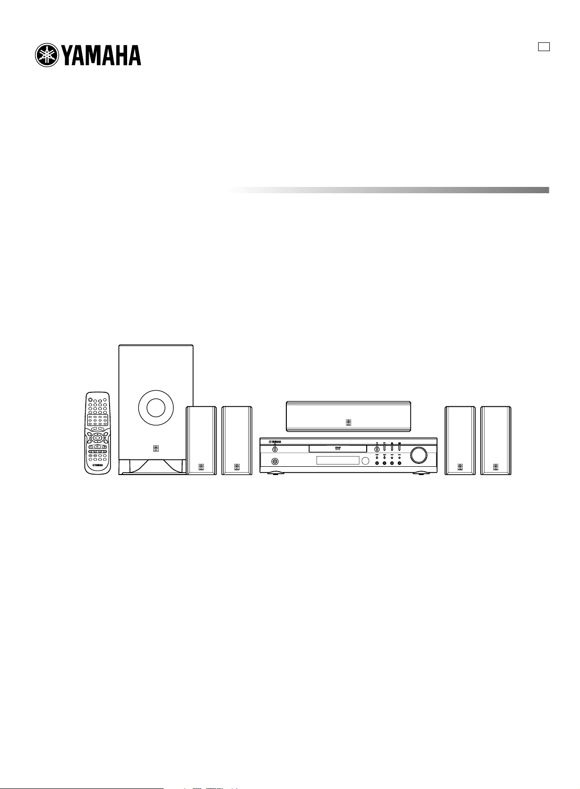
DVD HOME THEATER SOUND SYSTEM
PHONES
STANDBY/ON
FM MODE
TUNING
SURROUND BASS MUSIC INPUT
PRESET MEMORY
VOLUME
DVX-S60
U
DVX-S60: DVR-S60 + NX-S60S + NX-S60C + SW-S60
OWNER’S MANUAL
Page 2
IMPORTANT SAFETY INSTRUCTIONS
11 Power Sources – This product should be operated only from the type of
CAUTION
RISK OF ELECTRIC SHOCK
DO NOT OPEN
CAUTION: TO REDUCE THE RISK OF
ELECTRIC SHOCK, DO NOT REMOVE
COVER (OR BACK). NO USER-SERVICEABLE
PARTS INSIDE. REFER SERVICING TO QUALIFIED
SERVICE PERSONNEL.
• Explanation of Graphical Symbols
The lightning flash with arrowhead symbol, within
an equilateral triangle, is intended to alert you to the
presence of uninsulated “dangerous voltage” within
the product’s enclosure that may be of sufficient
magnitude to constitute a risk of electric shock to
persons.
The exclamation point within an equilateral triangle
is intended to alert you to the presence of important
operating and maintenance (servicing) instructions in
the literature accompanying the appliance.
WARNING
TO REDUCE THE RISK OF FIRE OR ELECTRIC SHOCK,
DO NOT EXPOSE THIS UNIT TO RAIN OR MOISTURE.
1 Read Instructions – All the safety and operating instructions should be
read before the product is operated.
2 Retain Instructions – The safety and operating instructions should be
retained for future reference.
3 Heed Warnings – All warnings on the product and in the operating
instructions should be adhered to.
4 Follow Instructions – All operating and use instructions should be
followed.
5 Cleaning – Unplug this product from the wall outlet before cleaning. Do
not use liquid cleaners or aerosol cleaners. Use a damp cloth for
cleaning.
6 Attachments – Do not use attachments not recommended by the product
manufacturer as they may cause hazards.
7 Water and Moisture – Do not use this product near water – for example,
near a bath tub, wash bowl, kitchen sink, or laundry tub; in a wet
basement; or near a swimming pool; and the like.
8 Accessories – Do not place this product on an unstable cart, stand, tripod,
bracket, or table. The product may fall, causing serious injury to a child
or adult, and serious damage to the product. Use only with a cart, stand,
tripod, bracket, or table recommended by the manufacturer, or sold with
the product. Any mounting of the product should follow the
manufacturer’s instructions, and should use a mounting accessory
recommended by the manufacturer.
9 A product and cart combination should be moved with
care. Quick stops, excessive force, and uneven surfaces
may cause the product and cart combination to overturn.
10 Ventilation – Slots and openings in the cabinet are
provided for ventilation and to ensure reliable operation of the product
and to protect it from overheating, and these openings must not be
blocked or covered. The openings should never be blocked by placing the
product on a bed, sofa, rug, or other similar surface. This product should
not be placed in a built-in installation such as a bookcase or rack unless
proper ventilation is provided or the manufacturer’s instructions have
been adhered to.
power source indicated on the marking label. If you are not sure of the
type of power supply to your home, consult your product dealer or local
power company. For products intended to operate from battery power, or
other sources, refer to the operating instructions.
12 Grounding or Polarization – This product may be equipped with a
polarized alternating current line plug (a plug having one blade wider
than the other). This plug will fit into the power outlet only one way. This
is a safety feature. If you are unable to insert the plug fully into the
outlet, try reversing the plug. If the plug should still fail to fit, contact
your electrician to replace your obsolete outlet. Do not defeat the safety
purpose of the polarized plug.
13 Power-Cord Protection – Power-supply cords should be routed so that
they are not likely to be walked on or pinched by items placed upon or
against them, paying particular attention to cords at plugs, convenience
receptacles, and the point where they exit from the product.
14 Lightning – For added protection for this product during a lightning
storm, or when it is left unattended and unused for long periods of time,
unplug it from the wall outlet and disconnect the antenna or cable
system. This will prevent damage to the product due to lightning and
power-line surges.
15 Power Lines – An outside antenna system should not be located in the
vicinity of overhead power lines or other electric light or power circuits,
or where it can fall into such power lines or circuits. When installing an
outside antenna system, extreme care should be taken to keep from
touching such power lines or circuits as contact with them might be fatal.
16 Overloading – Do not overload wall outlets, extension cords, or integral
convenience receptacles as this can result in a risk of fire or electric
shock.
17 Object and Liquid Entry – Never push objects of any kind into this
product through openings as they may touch dangerous voltage points or
short-out parts that could result in a fire or electric shock. Never spill
liquid of any kind on the product.
18 Servicing – Do not attempt to service this product yourself as opening or
removing covers may expose you to dangerous voltage or other hazards.
Refer all servicing to qualified service personnel.
19 Damage Requiring Service – Unplug this product from the wall outlet
and refer servicing to qualified service personnel under the following
conditions:
a) When the power-supply cord or plug is damaged,
b) If liquid has been spilled, or objects have fallen into the product,
c) If the product has been exposed to rain or water,
d) If the product does not operate normally by following the operating
instructions. Adjust only those controls that are covered by the
operating instructions as an improper adjustment of other controls
may result in damage and will often require extensive work by a
qualified technician to restore the product to its normal operation,
e) If the product has been dropped or damaged in any way, and
f) When the product exhibits a distinct change in performance - this
indicates a need for service.
20 Replacement Parts – When replacement parts are required, be sure the
service technician has used replacement parts specified by the
manufacturer or have the same characteristics as the original part.
Unauthorized substitutions may result in fire, electric shock, or other
hazards.
21 Safety Check – Upon completion of any service or repairs to this
product, ask the service technician to perform safety checks to determine
that the product is in proper operating condition.
22 Wall or Ceiling Mounting – The unit should be mounted to a wall or
ceiling only as recommended by the manufacturer.
2II
Page 3
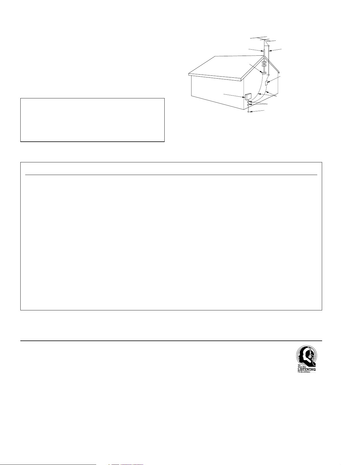
23 Heat – The product should be situated away from heat sources such as
EXAMPLE OF ANTENNA GROUNDING
MAST
GROUND
CLAMP
ANTENNA
LEAD IN
WIRE
ANTENNA
DISCHARGE UNIT
(NEC SECTION 810–20)
GROUNDING CONDUCTORS
(NEC SECTION 810–21)
GROUND CLAMPS
POWER SERVICE GROUNDING
ELECTRODE SYSTEM
(NEC ART 250. PART H)
ELECTRIC
SERVICE
EQUIPMENT
NEC – NATIONAL ELECTRICAL CODE
radiators, heat registers, stoves, or other products (including amplifiers)
that produce heat.
24 Outdoor Antenna Grounding – If an outside antenna or cable system is
connected to the product, be sure the antenna or cable system is
grounded so as to provide some protection against voltage surges and
built-up static charges. Article 810 of the National Electrical Code,
ANSI/NFPA 70, provides information with regard to proper grounding of
the mast and supporting structure, grounding of the lead-in wire to an
antenna discharge unit, size of grounding conductors, location of antenna
discharge unit, connection to grounding electrodes, and requirements for
the grounding electrode.
Note to CATV system installer:
This reminder is provided to call the CATV system installer’s attention to
Article 820-40 of the NEC that provides guidelines for proper grounding
and, in particular, specifies that the cable ground shall be connected to the
grounding system of the building, as close to the point of cable entry as
practical.
FCC INFORMATION (for US customers)
1. IMPORTANT NOTICE : DO NOT MODIFY THIS UNIT!
This product, when installed as indicated in the instructions
contained in this manual, meets FCC requirements. Modifications
not expressly approved by Yamaha may void your authority, granted
by the FCC, to use the product.
2. IMPORTANT : When connecting this product to accessories and/
or another product use only high quality shielded cables. Cable/s
supplied with this product MUST be used. Follow all installation
instructions. Failure to follow instructions could void your FCC
authorization to use this product in the USA.
3. NOTE : This product has been tested and found to comply with the
requirements listed in FCC Regulations, Part 15 for Class “B”
digital devices. Compliance with these requirements provides a
reasonable level of assurance that your use of this product in a
residential environment will not result in harmful interference with
other electronic devices.
This equipment generates/uses radio frequencies and, if not
installed and used according to the instructions found in the users
manual, may cause interference harmful to the operation of other
electronic devices.
We Want You Listening For A Lifetime
YAMAHA and the Electronic Industries Association’s Consumer Electronics
Group want you to get the most out of your equipment by playing it at a safe
level. One that lets the sound come through loud and clear without annoying
blaring or distortion – and, most importantly, without affecting your sensitive
hearing.
Compliance with FCC regulations does not guarantee that
interference will not occur in all installations. If this product is found
to be the source of interference, which can be determined by turning
the unit “OFF” and “ON”, please try to eliminate the problem by
using one of the following measures:
Relocate either this product or the device that is being affected by the
interference.
Utilize power outlets that are on different branch (circuit breaker or
fuse) circuits or install AC line filter/s.
In the case of radio or TV interference, relocate/reorient the antenna.
If the antenna lead-in is 300 ohm ribbon lead, change the lead-in to
coaxial type cable.
If these corrective measures do not produce satisfactory results, please
contact the local retailer authorized to distribute this type of product. If
you can not locate the appropriate retailer, please contact Yamaha
Electronics Corp., U.S.A. 6660 Orangethorpe Ave, Buena Park, CA
90620.
The above statements apply ONLY to those products distributed by
Yamaha Corporation of America or its subsidiaries.
Since hearing damage from loud sounds is often undetectable
until it is too late, YAMAHA and the Electronic Industries
Association’s Consumer Electronics Group recommend you to
avoid prolonged exposure from excessive volume levels.
III
3
Page 4
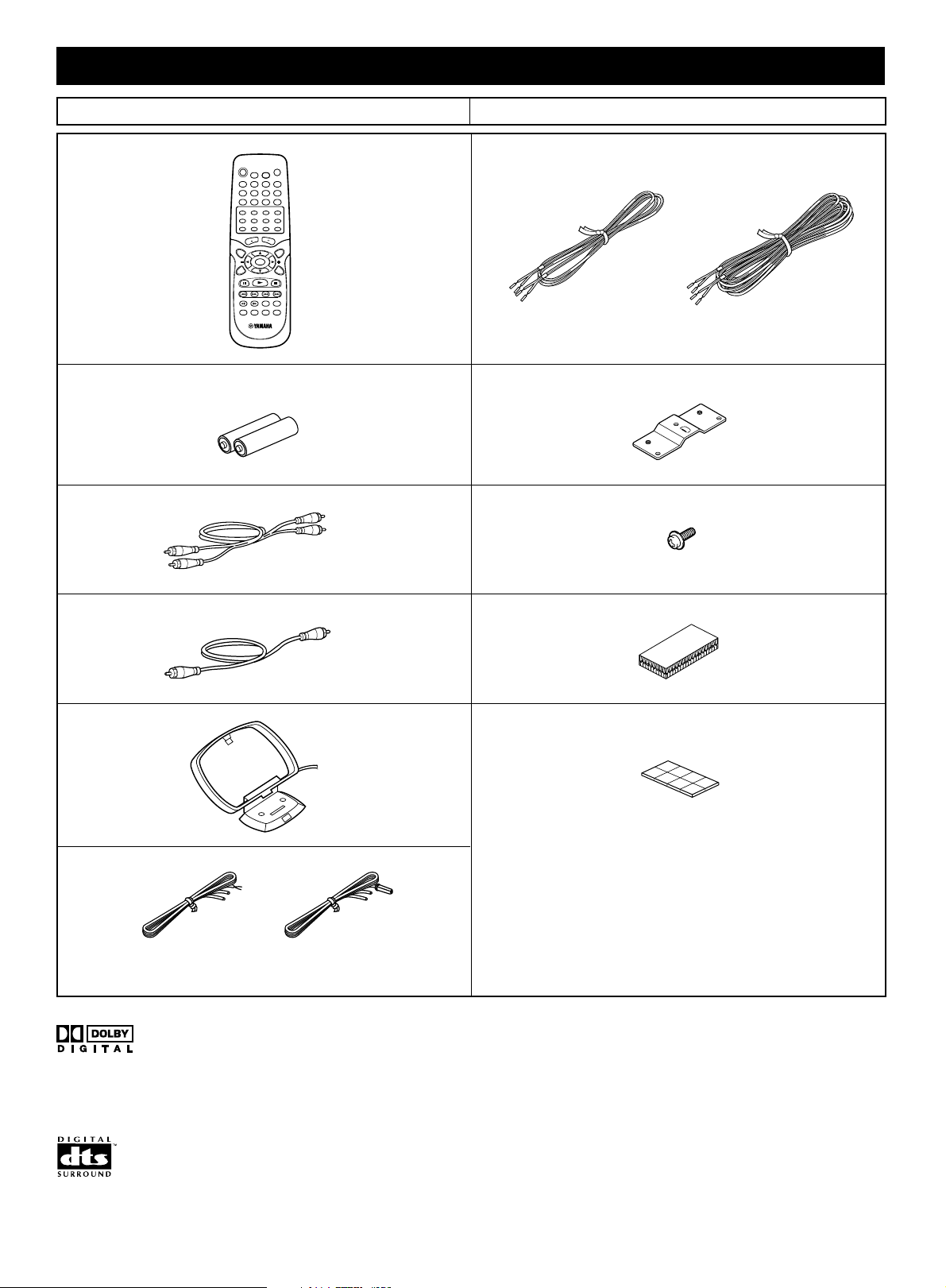
CHECKING THE ACCESSORIES ● Check your package to make sure it contains the following items.
DVR-S60 NX-SW60 (NX-S60S x 4, NX-S60C, SW-S60)
● Remote control
● Batteries (size AA, UM/SUM-3, R6, HP-7)
● Audio pin cable
● Video pin calbe
● Speaker cables
[5m]
X 4 X 2
● Mounting brackets (for NX-S60S)
● Screws (for NX-S60S)
● Fasteners (for NX-S60C)
[15m]
X 4
X 4
● AM loop antenna
● Indoor FM antenna
(U.S.A., Canada, Australia,
China, Korean and General
models)
Manufactured under license from Dolby Laboratories.
“Dolby”, “Pro Logic”, and the double-D symbol are trademarks
of Dolby Laboratories.
(U.K. and Europe models)
X 2
● Nonskid pads (for NX-S60S)
X 2
This product incorporates copyright protection technology that
is protected by method claims of certain U.S. patents and other
intellectual property rights owned by Macrovision Corporation
and other rights owners. Use of this copyright protection
technology must be authorized by Macrovision Corporation,
and is intended for home and other limited viewing uses only
unless otherwise authorized by Macrovision Corporation.
Reverse engineering or disassembly is prohibited.
“DTS” and “DTS Digital Surround” are registered trademarks of
Digital Theater Systems, Inc.
4
IV
Page 5
CAUTION: READ THIS BEFORE OPERATING YOUR SYSTEM.
1 To assure the finest performance, please read this manual
carefully. Keep it in a safe place for future reference.
2 Do not install this equipment in a confined space, such as a book
case or built in cabinet.
3 Locate this system away from other electrical appliances, motors,
or transformers to avoid humming sounds. To prevent fire or
electrical shock, do not place this system where it may get exposed
to dripping or splashing, and never put any objects filled with
liquids, such as vases, on the top of the system.
4 Do not expose this system to sudden temperature changes from
cold to hot, and do not locate this system in a environment with
high humidity (i.e. a room with a humidifier) to prevent
condensation inside this system, which may cause an electrical
shock, fire, damage to this system, and/or personal injury.
5 Avoid installing this system in a place where foreign objects and
liquid might fall. It might cause a fire, damage to this system and/or
personal injury. Do not place the following objects on this system:
– Other components, as they may cause damage and/or
discoloration on the surface of this system.
– Burning objects (i.e. candles), as they may cause fire, damage to
this system, and/or personal injury.
– Containers with liquid in them, as they may cause electrical
shock to the user and/or damage to this system.
6 Do not cover this system with a newspaper, tablecloth, curtain, etc.
in order not to obstruct heat radiation. If the temperature inside this
system rises, it may cause fire, damage to this system, and/or
personal injury.
7 Do not plug in this system to a wall outlet until all connections are
complete.
8 Do not operate this system upside-down. It may overheat, possibly
causing damage.
9 Do not use force on switches, knobs and/or cables.
10 When disconnecting the power cable from the wall outlet, grasp the
plug; do not pull the cable.
11 Do not clean this system with chemical solvents; this might damage
the finish. Use a clean, dry cloth.
12 Only voltage specified on this system must be used. Using this
system with a higher voltage than specified is dangerous and may
cause fire, damage to this system, and/or personal injury. YAMAHA
will not be held responsible for any damage resulting from use of
this system with a voltage other than specified.
13 To prevent damage by lightning, disconnect the power cable from
the wall outlet during an electrical storm.
14 Take care of this system so that no foreign objects and/or liquid
drops inside this system.
15 Do not attempt to modify or fix this system. Contact qualified
YAMAHA service personnel when any service is needed. The
cabinet should never be opened for any reasons.
16 When not planning to use this system for long periods of time (i.e.
vacation), disconnect the AC power plug from the wall outlet.
17 Be sure to read the “TROUBLESHOOTING GUIDE” section on
common operating errors before concluding that this system is
faulty.
18 Before moving this system, press STANDBY/ON to set this system
in the standby mode, and disconnect the AC power plug from the
wall outlet.
19 VOLTAGE SELECTOR (General model only)
The VOLTAGE SELECTOR on the rear panel of DVR-S60 must be
set for your local main voltage BEFORE plugging into the AC main
supply.
Voltages are 110–120V/220–240V AC, 50/60 Hz.
This system is not disconnected from the AC power source as long
as it is connected to the wall outlet, even if this system itself is
turned off. This state is called the standby mode. In this state, this
system is designed to consume a very small quantity of power.
IMPORTANT
Please record the serial number of DVR-S60 in the space below.
MODEL:
Serial No.:
The serial number is located on the rear of DVR-S60.
Retain this Owner’s Manual in a safe place for future reference.
FOR CANADIAN CUSTOMERS
To prevent electric shock, match wide blade of plug to wide slot and
fully insert.
This Class B digital apparatus complies with Canadian ICES-003.
■ For U.K. customers
If the socket outlets in the home are not suitable for the plug supplied
with this appliance, it should be cut off and an appropriate 3 pin plug
fitted. For details, refer to the instructions described below.
Note
• The plug severed from the mains lead must be destroyed, as a plug
with bared flexible cord is hazardous if engaged in a live socket
outlet.
■ Special Instructions for U.K. Model
IMPORTANT
THE WIRES IN MAINS LEAD ARE COLOURED IN ACCORDANCE
WITH THE FOLLOWING CODE:
Blue: NEUTRAL
Brown: LIVE
As the colours of the wires in the mains lead of this apparatus may
not correspond with the coloured markings identifying the terminals
in your plug, proceed as follows:
The wire which is coloured BLUE must be connected to the terminal
which is marked with the letter N or coloured BLACK. The wire
which is coloured BROWN must be connected to the terminal which
is marked with the letter L or coloured RED.
Making sure that neither core is connected to the earth terminal of
the three pin plug.
DANGER
Visible laser radiation when open. Avoid direct exposure to beam.
When this system is plugged to the wall outlet, do not place your eyes
close to the opening of the disc tray and other openings to look into
inside.
The laser component in this product is capable of emitting radiation
exceeding the limit for Class 1.
E-1
Page 6

CONTENTS
IMPORTANT SAFETY INSTRUCTIONS....................... II
CHECKING THE ACCESSORIES ............................... IV
CAUTION ....................................................................... 1
CONTROLS ................................................................... 3
Front panel ......................................................................... 3
Display ................................................................................ 3
REMOTE CONTROL ..................................................... 4
Controls .............................................................................. 4
Installing batteries in the remote control ............................. 5
Using the remote control .................................................... 5
SPEAKER PLACEMENT ............................................... 6
Placing the speakers .......................................................... 6
Placing the center speaker ................................................. 6
Mounting the front and surround speakers ......................... 7
BASIC CONNECTIONS ................................................. 8
Speaker connections .......................................................... 8
Antenna connections .......................................................... 9
Connecting to a TV with the video pin cable ...................... 9
ADDITIONAL CONNECTION EXAMPLES ..................10
Connecting to a TV with an S video cable ........................ 10
Connecting to a TV with a component video cable .......... 10
VCR connections .............................................................. 10
Progressive-scan TV connections .................................... 11
Headphones ..................................................................... 11
BASIC OPERATION..................................................... 12
Turning the power on and off ............................................ 12
Direct start function .......................................................... 12
Selecting the source .........................................................12
Adjusting the volume ........................................................ 12
To reduce the volume temporarily .................................... 12
Bass extension ................................................................. 12
Selecting the sound mode ................................................ 12
What to do if ... ................................................................. 12
ADJUSTING THE CLOCK ...........................................12
SELECTING THE SURROUND MODE ....................... 13
Selecting Dolby Pro Logic mode ...................................... 13
PLAYABLE DISCS ....................................................... 14
DISC PLAY ................................................................... 15
Preparations ..................................................................... 15
Loading a disc .................................................................. 15
Starting play ..................................................................... 15
Stopping play .................................................................... 15
SETTINGS ON THE SET UP MENU ...........................16
Common procedures of settings ...................................... 16
Language ....................................................................16
Display ........................................................................ 16
Speaker....................................................................... 17
Parental....................................................................... 17
VARIOUS DISC PLAYING FUNCTIONS ..................... 18
Selecting a DVD menu [DVD] ........................................... 18
Selecting a title menu [DVD] ............................................. 18
Return button (RETURN) [Video CD] ...............................18
Chapter (Track) skip ......................................................... 18
Title search [DVD]............................................................. 18
Chapter search [DVD] ...................................................... 18
Track search [Video CD] [CD]........................................... 18
Time search ...................................................................... 18
Fast play ........................................................................... 18
Slow-motion play .............................................................. 18
Still picture (Pause) .......................................................... 18
Frame by frame advance play [DVD] [Video CD]................ 18
Picture zoom [DVD] [Video CD] ........................................ 19
Viewing from a desired camera angle
(Multi-Angle) [DVD].......................................................... 19
Angle replay [DVD] ........................................................... 19
Repeat play ...................................................................... 19
Programmed play [Video CD] [CD]................................... 19
Selecting subtitle language [DVD] ....................................20
Selecting audio soundtrack language
(Multi-Language) [DVD] .................................................... 20
Changing the audio channel output [Video CD] .............. 20
Selecting on-screen information .......................................20
MP3 CD OPERATION .................................................. 21
MP3 CD information ......................................................... 21
MP3 CD play .................................................................... 21
LANGUAGE CODE LIST ............................................. 22
LISTENING TO VIDEO SOURCES .............................. 23
LISTENING TO THE RADIO ........................................ 23
Automatic/Manual tuning ..................................................23
To preset stations ............................................................. 23
Listening to preset stations............................................... 23
To receive FM stereo broadcasts ..................................... 23
TIMER OPERATION .................................................... 24
Using the timer ................................................................. 24
Using the sleep timer ........................................................ 24
TROUBLESHOOTING GUIDE..................................... 25
SPECIFICATIONS........................................................ 26
E-2
Page 7
C
T
DOLBY DIGITAL
DOLBY
PL DTS
ST MONO
kHz
PROG. ALL 1
MHz
REP.
SLEEP
ON OFF
1 2 5 6
8
9
151618 10
111417
1213
7
3 4
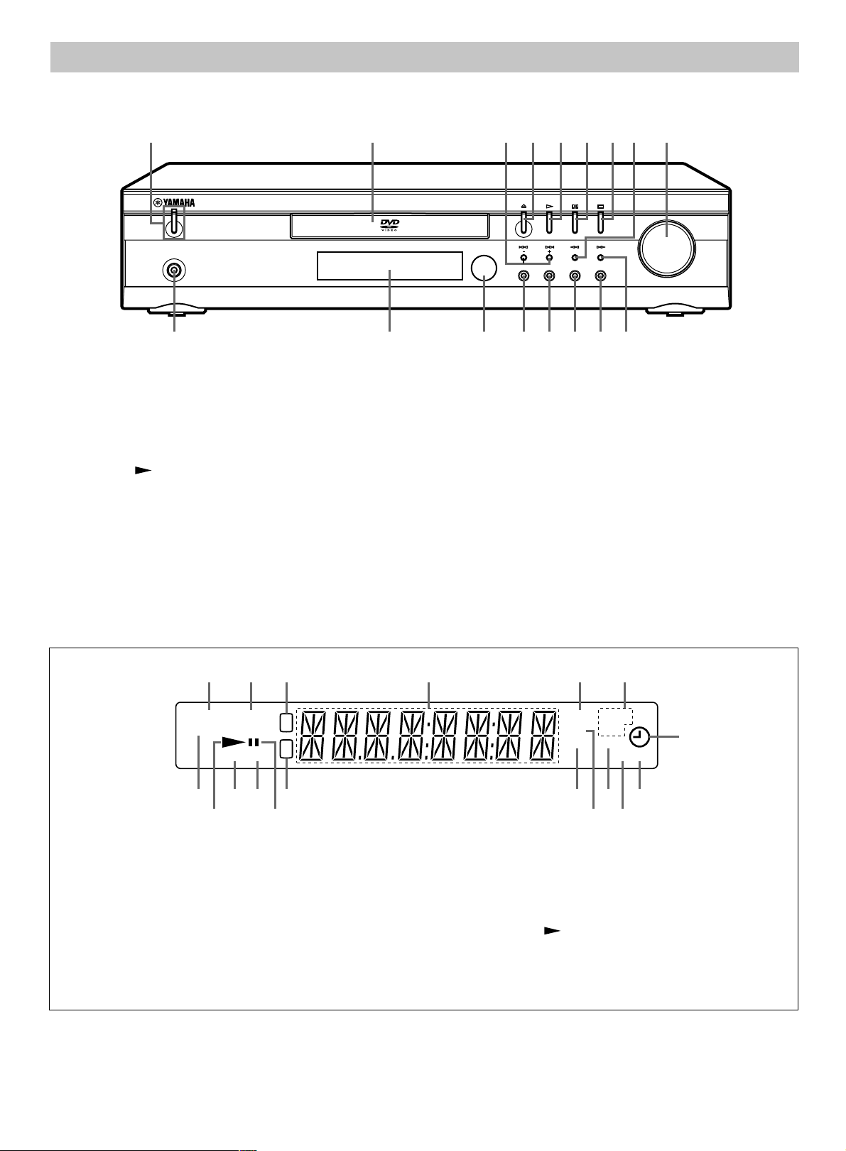
CONTROLS
PHONES
STANDBY/ON
FM MODE
TUNING
SURROUND BASS MUSIC INPUT
PRESET MEMORY
VOLUME
1 2 384 5 6 7 9
1011121314151617
Front panel
1. STANDBY/ON button, Standby indicator
2. Disc tray
3. f/TUNING – button, e/TUNING + button
4. Open/Close button (q)
5. Play button (
6. FM MODE button [see page 23.]/Pause button (k)
7. Stop button (n)
8. d/PRESET button
9. VOLUME control
)
Display
10. c/MEMORY button
11. INPUT button
12. MUSIC button [see page 12.]
13. BASS button [see page 12.]
14. SURROUND button [see page 13.]
15. Remote control sensor
16. Display
17. PHONES jack
1. Dolby Pro Logic indicator (DOLBY PL)
2. DTS indicator (DTS)
3. Title and Track indicator (T)
4. Message or number indicators
(Title, chapter, track, playing time or other information)
5. Program indicator (PROG.) [see page 19, 23.]
6. Repeat mode indicators (ALL, 1, REP.) [see page 19.]
7. Timer indicator (0) [see page 24.]
8. Timer off indicator (OFF) [see page 24.]
9. Timer on indicator (ON) [see page 24.]
10. Sleep indicator (SLEEP) [see page 24.]
11. Kilohertz indicator (kHz)
12. Megahertz indicator (MHz)
13. Chapter indicator (C)
14. Pause indicator (k)
15. FM mono indicator (MONO) [see page 23.]
16. FM stereo indicator (ST) [see page 23.]
17. Play indicator ( )
18. Dolby Digital indicator (DOLBY DIGITAL)
E-3
Page 8
REMOTE CONTROL
1 2 3 4
5 6 7 8
9 0
10
CANCEL
SET UP
ANGLE REPLAY ZOOM
SLEEP TIMER ADJUST
CLOCK
FM MODE
BASS TEST LEVEL TUNER
MUTE
SURROUND
MUSIC
VOLUME
TITLE
ON SCREEN
SEARCH
SEARCH MODE PROGRAM LAST MEMO REPEAT
SLOW AUDIO
SUBTITLE
SKIP
RETURN
ENTER
MENU
INPUT
TUNING PRESET
SET/CLEAR
SHIFT
POWER
5
4
1
2
3
1 2 3 4
5 6 7 8
9 0
10
CANCEL
SET UP
ANGLE REPLAY ZOOM
SLEEP TIMER ADJUST
CLOCK
FM MODE
BASS TEST LEVEL TUNER
MUTE
SURROUND
MUSIC
VOLUME
TITLE
ON SCREEN
SEARCH
SEARCH MODE PROGRAM LAST MEMO REPEAT
SLOW AUDIO
SUBTITLE
SKIP
RETURN
ENTER
MENU
INPUT
TUNING PRESET
SET/CLEAR
SHIFT
POWER
27
26
25
6
7
8
9
24
23
20
22
11
13
15
14
16
17
18
10
12
21
19
Note:
In this instruction manual, any operation of pressing a button while
pressing the SHIFT button is described as follows.
Example: “Press SHIFT + 2 ANGLE buttons.”
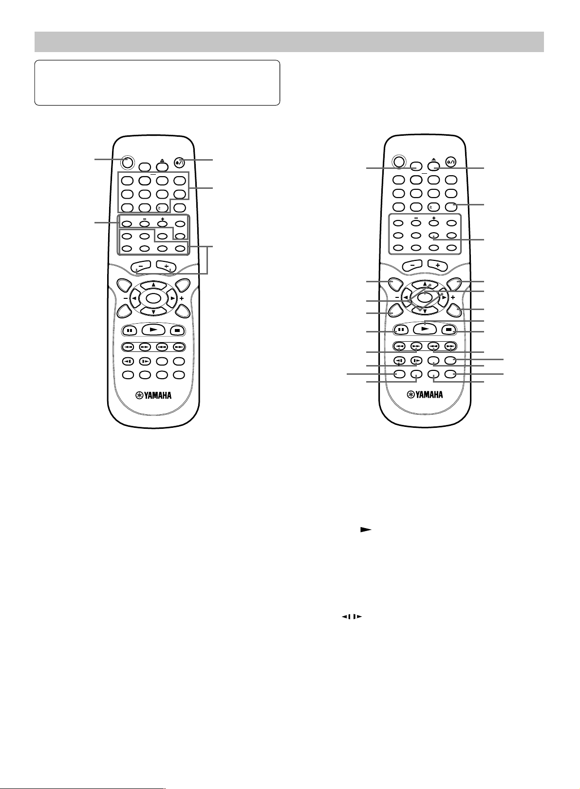
Controls
1. POWER button (z/I)
2. Number and other function buttons
Number buttons (1–9, 0,
ANGLE button [see page 19.]
ANGLE–REPLAY button [see page 19.]
ZOOM button [see page 19.]
SLEEP button [see page 24.]
TIMER button [see page 24.]
ADJUST button [see page 12.]
CLOCK button [see page 12.]
3. Amplifier controls
INPUT button
TEST tone [see page 13.]
SURROUND button [see page 13.]
BASS button [see page 12.]
MUSIC button [see page 12.]
MUTE button [see page 12.]
VOLUME –/+ buttons
4. Tuner controls
TUNER button (Tuner/Band select button)
PRESET button (Preset tuning button)
TUNING –/+ buttons [see page 23.]
[see page 23.]
FM MODE button [see page 23.]
5. SHIFT button
≥10)
6. Open/Close (q) button
7. SET/CLEAR button [see page 24.]/
CANCEL button [see page 18, 19.]
8. LEVEL button [see page 13.]
9. MENU button [see page 18.]
10. ENTER button
11. RETURN button [see page 18.]
12. Play button (
)
13. Stop button (n)
14. SKIP f/ e buttons
15. AUDIO button [see page 20.]
16. SUBTITLE button [see page 20.]
17. REPEAT button [see page 19.]
18. Last memory button (LAST MEMO) [see page 15.]
19. PROGRAM button [see page 19.]
20. SEARCH MODE button [see page 18.]
21. SLOW
/ buttons [see page 18.]
22. SEARCH d/ c buttons
23. Pause button (k)
24. ON SCREEN button [see page 20.]
25. 4, a, 5, b buttons
26. TITLE button [see page 18.]
27. SET UP button [see page 16.]
E-4
Page 9
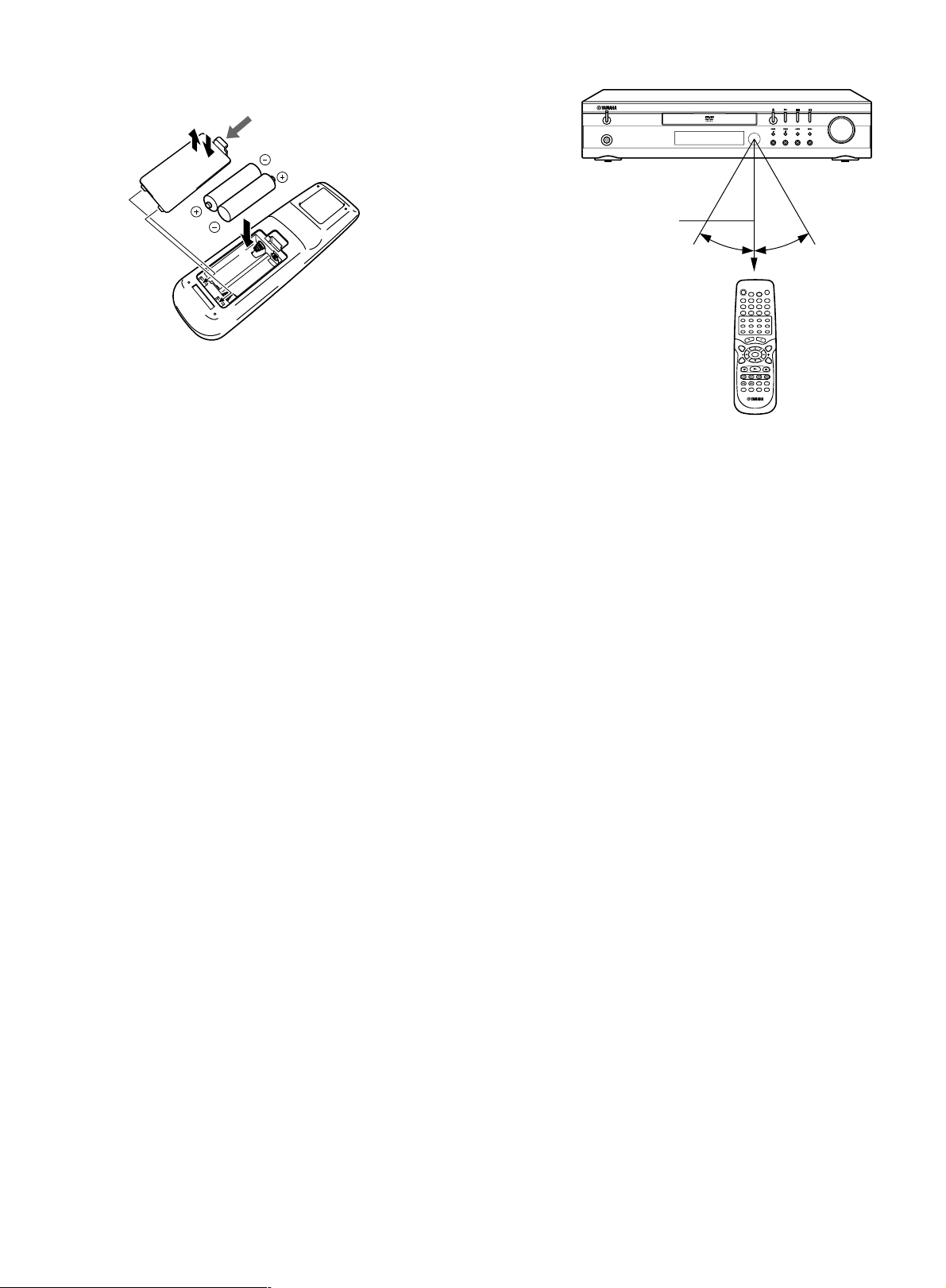
Installing batteries in the remote control
1
3
2
PHONES
STANDBY/ON
FM MODE
TUNING
SURROUND BASS MUSIC INPUT
PRESET MEMORY
VOLUME
Insert the batteries in the correct direction by aligning the + and – marks
on the batteries with the polarity markings (+ and –) inside the battery
compartment.
Press the tab.
Using the remote control
Approximately 6 m (20 feet)
1. Press the tab on the battery compartment cover in the direction of the
arrow and remove the cover.
2. Insert the two batteries (AA, R06, UM-3 type) with + and – oriented
properly.
3. Attach the cover so that it snaps into place.
Notes on batteries
• Change all of the batteries if you notice a decrease in the operating
range of the remote control.
• Do not use old batteries together with new ones.
• Do not use different types of batteries (such as alkaline and
manganese batteries) together. Read the packaging carefully as
these different types of batteries may have the same shape and
color.
• If the batteries have leaked, dispose of them immediately. Avoid
touching the leaked material or letting it come into contact with
clothing, etc. Clean the battery compartment thoroughly before
installing new batteries.
30⬚
30⬚
Handling the remote control
• Do not spill water or other liquids on the remote control.
• Do not drop the remote control.
• Do not leave or store the remote control in the following types of
conditions:
– high humidity or temperature such as near a heater, stove or bath;
– dusty places; or
– in places subject to extremely low temperatures.
E-5
Page 10
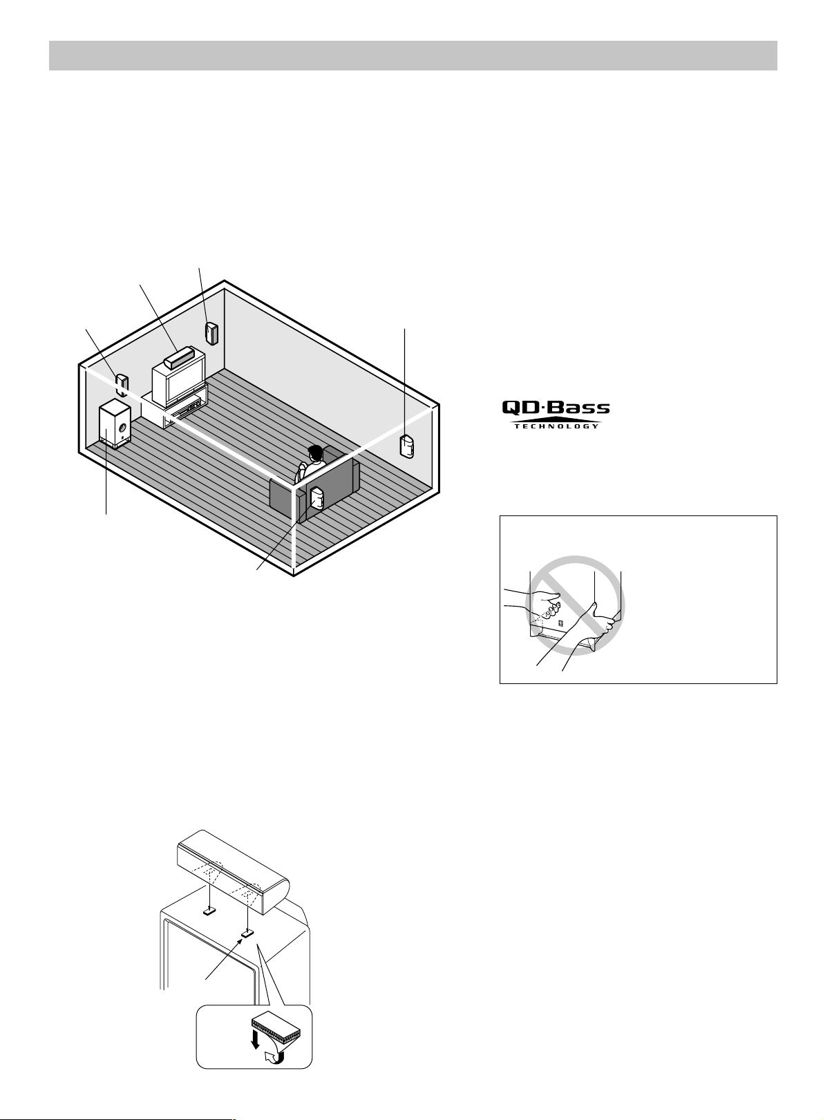
SPEAKER PLACEMENT
Before making connections, place all speakers in their respective positions. The positioning of the speakers is important because it controls the whole
sound quality of this system.
Place the speakers depending on your listening position by following the instructions below.
Note:
- In this speaker package, the same speakers (NX-S60S) are used for the front and surround speakers.
- Although the speaker system in this system is magnetically shielded, it may still affect the color on the television monitor when using this system
near the television. Adjust the relative positions of this system and the television if this happens.
Placing the speakers
Center speaker
Front left
speaker
Front right speaker
Surround right speaker
Front speakers: On both sides of and at approximately
Surround speakers:
Center speaker: Precisely between the front speakers.
Subwoofer: The position of the subwoofer is not
QD-Bass Technology
QD-Bass (Quatre Dispersion Bass) technology uses
square, pyramid-shaped reflective plates to radiate the
sound in four horizontal directions.
the same height as the TV set.
Behind your listening position, facing
slightly inward. About 1.8 m (approx.
6 feet) from the floor.
so critical because low bass tones are
not highly directional.
Subwoofer
Surround left speaker
Placing the center speaker
You can place the speaker on top of the TV if the top is flat, on the floor
under the TV, or inside the TV rack . Be sure to place the speaker in a stable
position.
When placing the speaker on top of the TV, to prevent the speaker from
falling, attach the provided fasteners at two points on the bottom of the
speaker and on the top of the TV.
Caution for carrying the subwoofer
Do not insert your hands
into the openings at the
lower part of the subwoofer
when carrying it.
If you touch the inside
speaker unit, it may be
damaged.
Remove the warning label
put by the factory setting
when using the subwoofer.
Note:
- Do not place the speaker on top of a TV whose area is smaller than
the bottom of the speaker. If placed, the speaker may fall and cause
injury.
- Do not place the speaker on top of a TV if the top is inclined.
- Do not touch the adhesive surface after peeling off the seal as this
will weaken its adhesive strength.
- Thoroughly wipe clean the surface where the fastener is to be
applied. Note that adhesive strength is weakened if the surface is
dirty, oily or wet and that this may cause the center speaker to drop.
E-6
Fastener
Peel off
the seal
Page 11

Mounting the front and surround speakers
Mount the speakers on a shelf, rack or directly on the floor, or hang them
on the wall.
To mount the speakers on a wall by using the holes on the
speakers’ back panels
1. Fasten screws into a firm wall or wall support as shown in the figure.
Round head screw
(not supplied)
Diam. 3.5–4 mm
Placing the the front/surround speakers
When placing the speakers on a flat surface, attach the included nonskid
pads to the corners on the bottom of the speakers. This prevents the
speakers from sliding around.
Nonskid pads
70 mm
Wall/ wall support
Min.
20 mm
70 mm
10 mm
2. Hang the speaker by mounting the holes on the protruding screws.
* Make sure that the screws are securely caught by the narrow parts
of the holes.
70 mm
WARNING
● Each speaker weighs 0.9 kg (2 lbs.). Do not mount them on thin
plywood or a wall composed of a soft surface material. If
mounted, the screws may pull out of the flimsy surface and the
speakers may fall. This may damage the speakers or cause
personal injury.
● Do not affix the speakers to a wall using nails, adhesives, or any
other unstable hardware. Long-term use and vibrations may
cause the speakers to fall.
● To avoid accidents resulting from tripping over loose speaker
cables, fix the cables to the wall.
● Select an appropriate position on the wall to mount the speaker
so that no one will injure his/her head or face.
If you want to mount a speaker on a commercially available
speaker stand for the front/surround speakers
The provided mounting bracket with 1 pair of screw holes (at an interval
of 60 mm) can be used to mount the speaker on a speaker stand.
* Those screw holes can be used with M4 screws only.
60 mm
1. Attach the bracket to the bottom of the speaker by using the provided
screw so that the convex part of the bracket fits in the grooved part on
the bottom of the speaker.
Mounting
bracket
Screw
Using the Yamaha Speaker Stand SPS-80 (option)
By using the Yamaha Speaker Stand SPS-80, speakers can be placed on
the floor.
SPS-80
* The SPS-80 is not available in some areas.
2. Mount the speaker on the speaker stand by using the screw holes on
the bracket.
Note:
The mounting bracket is provided for each speaker.
Note:
- Be careful not to let the speaker system fall, it might cause damage
or serious injuries.
- If you use another speaker system, please change the settings of
“Speaker” under “SETTINGS ON THE SET UP MENU” to the
proper settings for the speaker system. (See Page 17.)
E-7
Page 12

BASIC CONNECTIONS
VIDEO
S-VIDEO
(
DVD ONLY
)
MONITOR OUT
LR LR
SPEAKERS
8
Ω
CENTERFRONT
SUB
WOOFER
REAR
SURROUND
VIDEO 1 VIDEO 2
VIDEO
AUDIO
IN OUTININ
INOUT
L
R
L
R
VIDEO OUT SELECT
(
DVD ONLY
)
VIDEO OUT
SCAN SELECT
S-VIDEOCOMPONENT
COMPONENT
VIDEO OUT
480
p
/480i
(
DVD ONLY
)
Y
P
B
PR
SELECTABLE INTERLACE
480p/480i 480i
(
DVD ONLY
)
FRONT R
FRONT L
CENTER
REAR R
REAR L SUBWOOFER
Selecting TV system (for General model only)
Before connecting, set the TV SYSTEM switch (rear of the unit) to the
position of your local TV system (PAL or NTSC).
Speaker connections
Be sure all connections are made correctly, that is to say, L (left) to L, R
(right) to R, “+” to “+” and “–” to “–”.
Label of the Color tube Use
speaker cable
FRONT R Red Front right speaker
FRONT L White Front left speaker
CENTER Green Center speaker
REAR R Gray Surround right speaker
REAR L Blue Surround left speaker
SUBWOOFER Purple Subwoofer
Front right speaker
Black Red
Front left speaker
Black Red
After all connections have been made, connect the power cable to
an AC outlet.
Note:
- Do not connect the power cable to an AC outlet until all connections
have been made.
- The system is not completely disconnected from the AC outlet when
the STANDBY/ON button is set to the standby mode.
Note:
• The label of the speaker is attached to each speaker cable. Connect
the speakers in accordance with the labels.
• Connect the color tube of the speaker cable to the plus (+) side of
each speaker. If the polarity of the speaker connections is incorrect,
the sound will be unnatural and lack bass.
• A cover is attached to the end of the speaker cable. Connect the
speakers after removing the cover.
Center speaker
Black Red
White
Gray
Green
Blue
Purple
Green
Purple
Red
DVR-S60 (U.S.A. model)
Gray
Red White
Blue
E-8
Black Red
Black Red Black Red
Surround right speaker Surround left speaker Subwoofer
Page 13

Antenna connections
TUNER
FM
ANT
AM
ANT
VIDEO 1
VIDEO
AUDIO
IN OUT
IN OUT
L
R
75
Ω
GND
FM
ANT
AM
ANT
75
Ω
GND
1
2
1
2
3
VIDEO
S-VIDEO
(
DVD ONLY
)
MONITOR OUT
LR LR
SPEAKERS
8
Ω
CENTERFRONT
SUB
WOOFER
SURROUND
TUNER
FM
ANT
AM
ANT
VIDEO 1 VIDEO 2
VIDEO
AUDIO
IN OUTININ
INOUT
L
R
L
R
75
Ω
GND
VIDEO OUT SELECT
(
DVD ONLY
)
VIDEO OUT
SCAN SELECT
S-VIDEOCOMPONENT
COMPONENT
VIDEO OUT
480
p
/480i
(
DVD ONLY
)
Y
P
B
P
R
SELECTABLE INTERLACE
U.C (US.CA
)
MADE IN CHINA
R-AUDIO-L VIDEO
AUDIO
VIDEO
INPUT
1
480p/480i 480i
(
DVD ONLY
)
Outdoor FM antenna
(not supplied)
AM loop antenna
AM loop antenna
Set up the loop antenna.
Indoor FM antenna
In areas close to a transmitter the simple indoor antenna is sufficient to
receive broadcasts. Extend the antenna wire as straight as possible and,
while listening to the sound from the system, secure it in a position which
yields minimal distortion and noise.
In fringe areas or where reception is distorted or noisy, an external
antenna (not supplied) should be connected instead of the simple indoor
antenna. Consult your dealer.
DVR-S60
(U.S.A. model)
DVR-S60
Unwind the antenna wires, then connect them to the AM
ANT terminals. Place the loop antenna in a position which
yields the best AM reception, or attach it to a wall or other
surface.
Screws (not supplied)
Note:
To minimize noise, the speakers, power cable and any
other cable should not come close to the indoor or
external antenna cable and AM loop antenna . Do not
place the antenna cables close to the system.
Connecting to a TV with the video pin cable
Connect the included or commercially available video pin cable between the MONITOR OUT VIDEO jack of the unit and the video input jack of the TV.
Video pin cable
DVR-S60 (U.S.A. model)
TV
Notes on connections
- Please refer to the instruction manuals for the components that you are connecting (TV, etc.).
- When you connect the unit to your TV and other equipment, be sure to turn off the power and disconnect all of the equipments from the AC outlet
- Do not connect the MONITOR OUT (S VIDEO/VIDEO) and COMPONENT VIDEO OUT jacks of the unit to a VCR directly. The playback
- Please consult your local audio/video dealer for more details.
until all the connections have been made.
picture will be distorted because DVD discs are copy protected.
E-9
Page 14

ADDITIONAL CONNECTION EXAMPLES
VIDEO
S-VIDEO
(
DVD ONLY
)
MONITOR OUT
LR LR
SPEAKERS
8
Ω
CENTERFRONT
SUB
WOOFER
SURROUND
VIDEO OUT
SCAN SELECT
S-VIDEOCOMPONENT
COMPONENT
VIDEO OUT
480
p
/480i
(
DVD ONLY
)
Y
P
B
PR
SELECTABLE INTERLACE
U
MAD
COMPONENT VIDEO INPUT
YCBCR
480p/480i 480i
(
DVD ONLY
)
VIDEO OUT SELECT
(
DVD ONLY
)
2
1
VIDEO
S-VIDEO
(
DVD ONLY
)
MONITOR OUT
LR LR
SPEAKERS
8
Ω
CENTERFRONT
SUB
WOOFER
SURROUND
VIDEO OUT
SCAN SELECT
SELECTABLE INTERLACE
U.C (U
MADE IN
S-VIDEO
IN 1
480p/480i 480i
(
DVD ONLY
)
S-VIDEOCOMPONENT
VIDEO OUT SELECT
(
DVD ONLY
)
1
2
VIDEO
S-VIDEO
(
DVD ONLY
)
MONITOR OUT
LR LR
SPEAKERS
8
Ω
CENTERFRONT
SUB
WOOFER
SURROUND
TUNER
FM
ANT
AM
ANT
VIDEO 1 VIDEO 2
VIDEO
AUDIO
IN OUTININ
INOUT
L
R
L
R
75Ω
GND
VIDEO OUT SELECT
(
DVD ONLY
)
VIDEO OUT
SCAN SELECT
S-VIDEOCOMPONENT
COMPONENT
VIDEO OUT
480
p
480i
(
DVD ONLY
)
Y
P
B
PR
SELECTABLE INTERLACE
VHF/UHF
FROM ANT.
IN
OUT
TO TV
IN OUT
34
LINE1(AUX1)
VIDEO
CH.
L
R
L
R
AUDIO
VHF/UHF
FROM ANT.
IN
OUT
TO TV
IN OUT
34
LINE1(AUX1)
VIDEO
CH.
L
R
L
R
AUDIO
1
2
3
4
5
6
For connections, use the included or commercially available connection
cables suitable for respective connections.
Connecting to a TV with an S video cable
Please follow the steps below before turning on the power.
1. If your TV has an S video input jack, connect the unit as shown in the
figure. You can enjoy clearer picture playback.
2. Set the VIDEO OUT SELECT switch to S VIDEO.
Connecting to a TV with a component video cable
Please follow the steps below before turning on the power.
1. If your TV has component video input jacks, connect the unit as
shown in the figure. You can enjoy high quality picture playback.
2. Set the VIDEO OUT SELECT switch to COMPONENT.
VCR connections
With this connection, it is possible to watch and listen to videocassettes or
other video equipment.
Connect the 1st VCR as shown in figure 1–4.
If using the 2nd VCR or other video equipment, connect it as shown in
figure 5–6.
DVR-S60 (U.S.A. model)
TV
S Video cable
DVR-S60 (U.S.A. model)
TV
Component video cable
Video pin cable
DVR-S60 (U.S.A.
model)
Video pin cable
Video pin
cable
VCR (1st)
VCR (2nd)
Audio pin
cable
Audio pin
cable
Audio pin
cable
Note:
- The picture from the VCR may be distorted in some cases.
- If you use the VCR, you must connect the video pin cable between the MONITOR OUT VIDEO jack of the unit and the video input jack of the TV.
There are no VCR video signals from the MONITOR OUT S VIDEO and COMPONENT VIDEO OUT jacks of the unit.
-
<For U.S.A., Canada and Korean models>
Be sure to check and/or change the settings of the VIDEO OUT SELECT and VIDEO OUT SCAN SELECT switches before turning on this system.
If the setting of either or both switches is changed during play, picture may be disturbed or disappear from the monitor. In such a case, turn this
system off and then on again.
<For U.K., Europe, Australia, China and General models>
Be sure to check and/or change the setting of the VIDEO OUT SELECT switch before turning on this system. If the setting of this switch is changed
during play, picture may be disturbed or disappear from the monitor. In such a case, turn this system off and then on again.
Do not connect this system to a TV through a VCR. If you do so, the picture may not be played back properly due to the copyright
protection technology incorporated in this system.
E-10
Page 15

VIDEO
S-VIDEO
(
DVD ONLY
)
MONITOR OUT
LR LR
SPEAKERS
8
Ω
CENTERFRONT
SUB
WOOFER
TUNER
FM
ANT
AM
ANT
VIDEO 1 VIDEO 2
VIDEO
AUDIO
IN OUTININ
INOUT
L
R
L
R
75Ω
GND
S-VIDEOCOMPONENT
COMPONENT
VIDEO OUT
480
p
/480i
(
DVD ONLY
)
Y
P
B
PR
U.C (US.CA
)
MADE IN CHINA
COMPONENT VIDEO INPUT
YC
B/PBCR/PR
REAR
SURROUND
VIDEO OUT SELECT
(
DVD ONLY
)
VIDEO OUT
SCAN SELECT
SELECTABLE INTERLACE
480p/480i 480i
(
DVD ONLY
)
2
3
1
+
Progressive-scan TV connections (for U.S.A., Canada and Korean models only)
Your TV must be capable of handling progressive scanning and have component video input capability.
Component video cable
Green
Blue
Red
DVR-S60 (U.S.A. model)
To AC outlet
Please follow the steps below before turning on the power.
1. Connect the component video cable (not supplied) between the
COMPONENT VIDEO OUT jacks of the unit and the COMPONENT
VIDEO INPUT jacks of the TV.
2. Set the VIDEO OUT SELECT switch to the COMPONENT position.
3. Set the VIDEO OUT SCAN SELECT switch to the SELECTABLE
position.
After all connections and settings on the rear panel are completed, turn on
the power of this system and the TV, then make the following setting.
4. Select “COMPONENT OUTPUT: PROGRESSIVE” in “Display” on
the SETTINGS ON THE SET UP MENU. (See page 16.)
Notes:
• Please refer to the instruction manual of your TV.
• When you connect the unit to your TV, be sure to turn off the power
and disconnect both units from the wall outlet until all the
connections have been made.
• After the above connections have been made, there are no video
signals from the MONITOR OUT VIDEO and VIDEO 1 VIDEO OUT
jacks.
Green
Blue
Red
TV with progressive-scan capability
Progressive Scanning
While interlaced scanning produces one frame of video in two fields,
progressive scanning creates one frame in one field. Conventional
interlaced scanning constitutes one second with 30 frames (60 fields), but
progressive scanning constitutes it with 60 frames from scratch. Progressive
scanning can reproduce sharper picture with high resolution for still image
or other picture containing long texts or horizontal lines.
This model has compliance with 480p (progressive) system.
Interlaced scanning
Progressive scanning
Do not connect the unit to a VCR directly. The playback picture
Headphones
Connect stereo headphones (not supplied) to the PHONES jack for monitoring or for private listening. The speakers are automatically disconnected when
will be distorted because DVD video discs are copy protected.
headphones are connected.
E-11
Page 16

BASIC OPERATION
ADJUSTING THE CLOCK
(Using the remote control)
Turning the power on and off
Press the STANDBY/ON button. The STANDBY indicator goes out. (After
connecting the power cable, when you press the STANDBY/ON button for
the first time, the volume-reset feature automatically sets the initial volume
level.)
To turn the power off, press the STANDBY/ON button again. The STANDBY
indicator lights up.
- When the power cable is connected to the AC outlet, the unit can be
controlled from the remote control.
Direct start function
If the following buttons are pressed when the unit is in the standby mode,
the unit turns on automatically and the selected source is activated.
Main unit
Remote control
, q
, TUNER, q
Selecting the source
Press the INPUT button to select the desired source. Each time the button
is pressed, the display changes as follows:
DVD
v
VIDEO 1 v VIDEO 2 v FM v AM v . . .
- When the source selection is changed, disc play is automatically
stopped.
Adjusting the volume
Turn the VOLUME control (or press the + or – VOLUME button on the
remote control). The volume level appears on the display (VOL 0 – VOL
39, MAX).
To reduce the volume temporarily (using the remote
control)
Press the MUTE button. The “MUTE” indicator flashes on the front panel
display. To restore the previous volume setting, press the MUTE button
again.
Bass extension
Press the BASS button to select the desired bass boost effect.
BASS OFF
v
BASS ON1 v BASS ON2 v BASS OFF . . .
Selecting the sound mode
Press the MUSIC button to select the sound mode matching the source to
be listened to.
POP: Pops, etc.
CLASSIC: Classical music, etc.
ROCK: Rock music, etc.
JAZZ: Jazz, etc.
Example: To set “PM 6:30”
1. Press the STANDBY/ON button to turn the power on.
2. Press the SHIFT + 0 CLOCK buttons. “AM 12:00” flashes.
3. Press the SHIFT + 8 ADJUST buttons.
The hour display flashes.
4. Press the TUNING – or + button to set the “hours”.
5. Press the SHIFT + 8 ADJUST buttons.
The minute display flashes.
6. Press the TUNING – or + button to set the “minutes”.
7. Press the SHIFT + 8 ADJUST buttons. The clock starts.
- The time can be set accurately by pressing the SHIFT + 8
ADJUST buttons when a time signal is heard.
To display the clock during operation
Press the SHIFT + 0 CLOCK buttons. Press both buttons again to return
to the original display.
Note:
When the display flashes because of a power failure, reset the time.
What to do if...
If the operation of the unit or display is not normal,
1. Disconnect the power cable.
2. While pressing both BASS and MUSIC buttons on the main unit at the
same time, connect the power cable. “RESET” briefly appears on the
display.
3. Resume operation.
E-12
Page 17

SELECTING THE SURROUND MODE
SURR OFF: Normal stereo sound
Using only the Front left, Front right and Subwoofer speakers (Fig. C)
Press the SURROUND button to select the surround mode. Each time the
button is pressed, the surround mode changes as follows:
v
DOLBY PL
v
SURR OFF v DOLBY PL . . .
Note:
Some discs may restrict the selection.
DOLBY PL: Dolby Pro Logic mode
When playing a program source encoded with Dolby Surround sound
(video tape, laser disc, DVD, etc.) (Fig. A)
Subwoofer
DOLBY 3: 3 channel mode
Using only the Front left, Center, Front right and Subwoofer speakers
(Fig. B)
Subwoofer
DOLBY 3 v DOLBY D v DTSv THEATER v HALL
Front
left
speaker
Surround
left
speaker
Front
left
speaker
Center
speaker
Center
speaker
Front
right
speaker
Surround
right
speaker
Front
right
speaker
Fig. A
Front
left
speaker
Subwoofer
Surround
left
speaker
Center
speaker
Front
right
speaker
Surround
right
speaker
Fig. C
Selecting Dolby Pro Logic mode
If you play a program source encoded with Dolby Surround or DTS sound
(video tape, laser disc, DVD etc.), follow the steps below.
Please use the remote control at the listening position.
1. Press the + or – VOLUME button to adjust the sound level from the
speakers.
2. Press the SURROUND button repeatedly until “DOLBY PL” appears.
3. Press the TEST button. “TTONE” appears and “FL” flashes.
The test tone will be heard from each speaker sequentially as follows:
TTONE
FL (Front left speaker)
C (Center speaker)
FR (Front right speaker)
RS (Surround right speaker)
LS (Surround left speaker)
4. Press the + or – VOLUME button until the test tone turns into a
comfortable level.
If the test tone level is not the same from each speaker, you may need
fine adjustment of the volume level. Please follow the steps as below.
Note:
If you make no operation, the original display returns after approximately
a minute.
1) Press the TEST button to turn the test tone off.
2)
Press the SURROUND button to select the desired surround mode.
3) Press the LEVEL button. “FNTL 0” appears.
4) Press the ENTER button repeatedly to select the speaker.
Surround
left
speaker
DOLBY D:
Dolby Digital 5.1 Channel mode
When DVD disc encoded with Dolby Digital 5.1 Channel is played
back, you can select “DOLBY D”. (Fig. A)
Note:
Center or Surround speakers do not sound with some discs.
DTS:
DTS Digital Surround mode
When DVD disc encoded with DTS Digital Surround System
(5.1ch) is played back, you can select “DTS”. (Fig. A)
Note:
Center or Surround speakers do not sound with some discs.
THEATER: “Theater” effect
HALL: “Hall” effect
When playing a program source which is not encoded with Dolby Surround
or DTS sound (Fig. A)
Surround
right
speaker
Fig. B
Display (Speaker)
FNTL (Front left speaker)
CENT (Center speaker)
FNTR (Front right speaker)
SURR (Surround right speaker)
SURL (Surround left speaker)
SUBW (Subwoofer)
5) Press the a or b button to adjust the volume level. (FNTL/FNTR:
“0” to “–10”, CENT/SURR/SURL/SUBW: “+10” to “–10”.)
6) Press the ENTER button.
7) Repeat step 4) to 6) for another speaker, if necessary.
8) Press the LEVEL button again to turn it off.
5. Press the TEST button to turn the test tone off. “TTONE” disappears.
6. Press the + or – VOLUME button to adjust the volume.
Notes:
- There is no Dolby Surround effect when monaural program material
is used.
- When receiving weak FM broadcasts, switch the Dolby Pro Logic off.
The sound quality may improve.
- When headphones are connected while any of the surround modes
are selected, the surround mode is switched off automatically. The
SURROUND button does not function while headphones are
connected.
- For other surround mode, please refer to “Selecting Dolby Pro Logic
mode” as above.
- This adjustment can be set at each source individually.
E-13
Page 18

PLAYABLE DISCS
3
2
3
LB16:9
2
ALL
ALL
ALL
ALL
ALL
12436
The following types of discs can be played on this unit.
Disc type and logo mark
Recorded
content
Audio
DVD Video
+
Video
Audio
Video CD
(Version 2.0)
Music CD
+
Video
Audio
Region number
Region number (Regional restriction code) is built-in to the DVD player
and DVD discs.
There is a region number on the rear of the unit.
The same region number or region number “ALL” of DVD discs can be
used on this unit.
Model
Region
Discs can be played
number of
this unit
U.S.A. and Canada
models
U.K. and Europe
models
Australia model
General and Korean
models
China model
“1”, “
” or a mark which
includes the region number
“1”.
“2”, “
” or a mark which
includes the region number
“2”.
“4”, “
” or a mark which
includes the region number
“4”.
“3”, “
” or a mark which
includes the region number
“3”.
“6”, “
” or a mark which
includes the region number
“6”.
Disc size
12 cm
8 cm
12 cm
8 cm
12 cm
8 cm
Approx. 4 hours (Single sided disc)
Approx. 8 hours (Double sided disc)
Approx. 80 minutes (Single sided disc)
Approx. 160 minutes (Double sided disc)
74 minutes
20 minutes
74 minutes
20 minutes
Maximum playing time
DVD discs are divided into titles, and the titles are sub-divided into
chapters.
Title 1
Chapter 1 Chapter 2
Chapter 1 Chapter 2 Chapter 3
Title 2
Video CD/Music CD disc
Video CD and Music CD discs are divided into tracks.
Track 1 Track 2 Track 3 Track 4 Track 5
Note:
- Only the above types of discs can be played on this unit.
DVD-Audio, DVD-ROM, DVD-RAM, CD-ROM, CDV, CD-G, DVD+RW,
DVD-RW, SVCD, CVD, SACD, Divx Video Discs, Photo CD, etc.
cannot be played. (Some DVD-R, DVD-RW and DVD+RW discs may
be played.)
- This unit can play back CD-R/RW discs that have music data or MP3
files as well. However, some CD-R/RWs can not be played back
depending on the recording conditions.
- A CD-R/RW that has no music data or non-MP3 files can not be played
back.
- This unit is to be used exclusively with the PAL or NTSC color system.
SECAM system discs cannot be used with this unit.
Notes on handling discs
DVD disc
There are marks on some DVD disc package.
Examples:
Multiple Languages
Multi-language subtitles
Multi-Angle
Multi-Aspect
Region number
E-14
- Do not expose the disc to direct sunlight, high humidity or high
temperature for extended periods of time.
- Discs should be returned to their cases after use.
- Do not apply paper or write anything on the disc surface.
- Handle a disc by its edge. Do not touch the recorded surface (glossy
side).
- Fingerprints and dust should be carefully wiped off the recorded
surface of the disc with a soft cloth.
Wipe in a straight motion from the center to the outside of the disc.
- Never use chemicals such as record cleaning sprays, antistatic
sprays or fluids, benzene or thinner to clean discs.
- Do not use a disc printed on its surface by a commercially available
label printer.
Page 19

DISC PLAY
C
ENTER
Important note:
- This “DISC PLAY” explains the basic instruction of the DVD
player section using the remote control unit.
- Some DVD or Video CD discs have different functions that may not
be explained in this instruction manual. You may need extra
instructions. In this case, please follow the instructions displayed
on the TV screen or the jacket or case of the disc.
” may appear on the TV screen during operation. This icon
- “
means that the function is not available on the current disc.
Preparations
- Press the STANDBY/ON button to turn on this unit.
- Turn on the TV and select the channel for the DVD player.
Select the playback picture size suitable for the aspect ratio of the TV.
(See “Display” under “SETTINGS ON THE SET UP MENU” on Page
16.)
- Select the desired language for the screen menus. (See “OSD” –
“Language” under “SETTINGS ON THE SET UP MENU” on Page 16.)
Note:
- Do not touch the disc tray while it is moving.
- Never place anything except a disc on the disc tray. Foreign objects
can damage the unit.
- Do not apply excessive force to the disc tray.
- Only one disc can be placed on the disc tray.
- To open or close the disc tray, be sure to use the q button. Do not press
the disc tray with your hand.
When an operation button is pressed, that operation is displayed
on the TV screen. The display turns off after several seconds.
If a disc is loaded, you can turn the unit on and begin play immediately
by pressing the
Loading a disc
1. Press the q button. “OPEN” appears on the display and the disc tray
opens.
2. Place the disc with the label facing up on the disc tray.
12 cm disc 8 cm disc
3. Press the q button again to close the disc tray.
- Some discs may start play automatically.
button.
If a menu appears on the TV screen...
Press the 4, a, 5 or b button (or the number
buttons), then press the ENTER button to select
the desired menu. Playback of the selected menu
will start.
Note:
For more details, please refer to the jacket or
case of the disc.
Remote control
Stopping play
- Press the n button once.
When you press the
point where you stopped.
Note:
Some discs may not resume play.
- Press the n button twice. The player stops completely.
When you press the
disc.
Continuing play from where you stopped watching (LAST
MEMORY PLAY) [DVD]
1. During play, press the LAST MEMO button at the point from which you
want to resume play later. “L.M.-STOP” appears on the display. Play
stops automatically.
2. Remove the disc or turn off the power.
3. Load the disc (and press the
Memory Play?” screen appears.
Last Memory Play?
Yes
No
Clear … The memory is released.
4. Press the 4 or 5 button to select “Yes”.
5. Press the ENTER button. Play resumes from the point where you
stopped. (If desired, press the LAST MEMO button again.)
Note:
- Points on up to 5 discs can be memorized.
- The Last Memory Play mode may not work correctly with some discs.
What is “PBC”?
“PBC” is an abbreviation for “Playback Control” that refers to control codes
prerecorded on Video CDs.
During playback of a Video CD with PBC, “PBC” appears on the display.
To lock the disc tray (Using the main unit)
You can lock the disc tray to prevent misuse of young children.
While the disc tray is opened, press the q button until “LOCKED”
appears on the TV screen.
- The q button will not function.
To release this mode, press the q button until “UNLOCKED” appears.
button, play starts automatically from the
button, play starts from the beginning of the
button), or turn on the power. “Last
Starting play
Press the button. The DVD function is selected and play starts
automatically.
Example:
Note:
- If “NO DISC” appears on the display, load the disc.
If the disc is loaded with the label side downward (and it is a single
sided disc), or if a badly scratched disc is loaded, “NO DISC” (or “NO
PLAY”) appears. If this occurs, load the disc correctly or replace the
disc.
- The producing method of commercially available discs may differ with
each disc. Though there may be a case that the sound becomes
intermittent just after the playback of a disc starts, this is dependent
on the disc and not a malfunction of this system.
E-15
Page 20

SETTINGS ON THE SET UP MENU
Language
Display
Language
Display
Speaker Parental
Once the following settings have been completed, the unit can always be operated under the same conditions.
The settings will be retained in the memory until they are changed, even if the power is turned off.
Common procedures of settings
1. Press the SET UP button in the stop mode. “SET UP MENU” appears on the TV screen.
2. Press the 4, a, 5 or b button, then press the ENTER button to select the menu. Please refer to the on-screen instructions.
3. Press the SET UP button to quit this menu.
Example:
Note:
- You cannot switch audio sound track languages if there is only one
language recorded on the disc.
- When you play a DVD disc, the player automatically displays the pre-
OSD: ENGLISH
AUDIO: DISC, ENGLISH, SPANISH, FRENCH, OTHERS
SUBTITLE: DISC, ENGLISH, SPANISH, FRENCH, OTHERS
DVD MENU: DISC, ENGLISH, SPANISH, FRENCH, OTHERS
(DISC: The first priority language recorded on the disc is
used.)
selected subtitle language if it is included on the disc.
- If “OTHERS” is selected, enter the language code. (See “LANGUAGE
CODE LIST” on Page 22.)
TV TYPE: 4:3 LB, 4:3 PS, 16:9
COMPONENT OUTPUT
PROGRESSIVE MODE*: AUTO, VIDEO, FILM
*
: INTERLACE, PROGRESSIVE
*: For U.S.A., Canada and Korean models only
TV TYPE:
Select the appropriate setting for your TV screen size.
4:3 LB (Letterbox):
Select when a conventional TV set is
connected.
When the wide screen disc is played back,
the black bands appear at the top and bottom
of screen.
4:3 PS (Panscan):
Select when a conventional TV set is
connected.
When the wide screen disc is played back, it
displays pictures cropped to fill to your TV
screen. The left and right edges are cut off.
16:9:
Select when a wide screen TV set is
connected.
Played in “FULL” size. (Setting the wide
screen TV to “FULL” mode is also necessary.)
Cut off
COMPONENT OUTPUT (U.S.A., Canada and Korean models only):
If you use a conventional TV and connect it to the COMPONENT VIDEO
OUT jacks (see page 10), select “INTERLACE”.
If you use a TV with progressive-scan capability and connect it to the
COMPONENT VIDEO OUT jacks (see page 11), select “PROGRESSIVE”.
Note:
- If the VIDEO OUT SELECT and VIDEO OUT SCAN SELECT switches
are not correct position, you cannot select “COMPONENT OUTPUT:
PROGRESSIVE”.
- If you select “COMPONENT OUTPUT: PROGRESSIVE” when using
a conventional TV, the TV screen is disturbed. In this case, turn off the
power, and then set the VIDEO OUT SCAN switch to the INTERLACE
position.
PROGRESSIVE MODE (U.S.A., Canada and Korean models only):
When “COMPONENT OUTPUT: PROGRESSIVE” is selected as above,
select “AUTO”, “VIDEO” or “FILM”.
AUTO:
It automatically selects the VIDEO (Video source) or FILM (Film source)
according to the played disc. Normally, select this mode.
VIDEO (Video source):
Major DVD-Video sources consist of video sources and film sources.
Select when playing a DVD video disc recorded with a video source or TV
program like drama, animation, etc. (30 frames per second, 60 fields).
FILM (Film source):
Major DVD-Video sources consist of video sources and film sources.
Select when playing a DVD video disc recorded with a movie film (24
frames per second).
Note:
- The screen size may differ depending on the DVD video discs.
- If you select 16:9 to get rid of the black bands on screen when wide
- In some discs, even if 4:3 PS is selected, the black bands may remain
E-16
screen disc is played back, picture may be slightly distorted.
on the screen.
Note:
- Initial setting is “AUTO”.
- If picture flickering occurs at “AUTO” mode, select “VIDEO” or “FILM”.
Page 21

Parental
D-RANGE CONTROL: OFF, ON
Speaker
FRONT SPEAKER: SMALL, LARGE
CENTER SPEAKER: SMALL, LARGE
SURROUND SPEAKER: SMALL, LARGE
SUBWOOFER: YES, NO
These are originally set suitable for the supplied speakers. However, you
can also change the settings as you prefer.
Make the settings as follows:
D-RANGE CONTROL (Dynamic range control):
It limits a big sound. Select “ON” or “OFF”.
FRONT SPEAKER/CENTER SPEAKER/SURROUND SPEAKER:
When using the supplied speakers, select “SMALL”.
SUBWOOFER:
When using the supplied subwoofer, select “YES”. If not, select “NO”.
Parental control
MPAA (Motion Picture Association of America) Guideline is a rating
system that provide advance cautionary information to parents about the
content of movie programs.
䡵 Setting method
1 ENTER PASSWORD
Enter a number in 4 digits, then press “ENTER”.
* Use the number buttons to enter 4-digit number.
2 To confirm, enter password again, then press “ENTER”.
* By following this step, the setting is finished.
Note
If you enter a wrong password, the following message appears on the
TV screen. Enter the correct password again.
Invalid password
Enter a number in 4 digits, then press “ENTER”.
䡵 Setting the desired parental level
1 Enter the password you have set.
2 Press 5 or 4 button to select “PARENTAL LEVEL”.
3 Press a or b button to select the desired level. The selectable levels
are as follows.
PARENTAL LEVEL: OFF, 1, 2, 3, 4, 5, 6, 7, 8
䡵 To change the password
1 Enter the password you have set.
2 Press 5 or 4 button to select “CHANGE PASSWORD”.
x
The parental lock level is equivalent to the following MPAA Rating System.
Level 7: NC-17 (No one 17 and under admitted)
Level 6: R (Restricted)
Level 4: PG13 (Parental guidance cautioned)
Level 3: PG (Parental guidance suggested)
Level 1: G (General audiences)
Some DVD discs contain a restriction level which enables parents to
prevent playback of discs by children. This DVD player is equipped with
a password designed to prevent children changing the level.
You cannot play DVD discs rated higher than the level you selected unless
you cancel the parental lock function.
For example, when you select level “5”, the DVD player will not play discs
with the rating of “6”, “7” or “8”. The information will appear on the TV
screen.
If you forget the password…
Enter “788444” to clear the current password.
Enter a new password and set the parental lock level again.
Note:
Some DVD discs may not respond to the parental lock settings. Make sure
this function works with your DVD discs.
For improvement, on screen displays subject to change
without notice.
CHANGE PASSWORD
Enter a number in 4 digits, then press “ENTER”.
* Use the number buttons to enter 4-digit number.
To confirm, enter password again, then press “ENTER”.
* By following this step, the setting is finished.
x
E-17
Page 22

VARIOUS DISC PLAYING FUNCTIONS
“ ” may appear on the TV screen during operation. This icon means
that the function is not available on the current disc.
Selecting a DVD menu [DVD]
1. Press the MENU button. The main menu screen appears.
Note:
Press the MENU button again to resume play.
2. Press the 4, a, 5 or b button (or the number buttons) to select the
desired menu then press the ENTER button. The selected menu play
starts.
Selecting a title menu [DVD]
1. Press the TITLE button. The title menu appears.
Note:
Press the TITLE button again to resume play from the scene when the
TITLE button was first pressed.
2. Press the 4, a, 5 or b button (or the number buttons) to select the
desired title then press the ENTER button. The selected title play
starts.
Note:
Selecting a DVD or title menu operation may differ depending on the disc
used and may not be possible on some discs.
Return button (RETURN) [Video CD]
Normally, it returns to the previous menu when the RETURN button is
pressed during play.
Note:
The operation differs according to the content of the Video CD.
Chapter (Track) skip
Chapter search [DVD]
1. Press the SEARCH MODE buttons twice during play. “CHAPTER
SEARCH...” screen appears.
2. Press the number button(s) to enter the chapter number. Play starts
from the selected chapter.
Track search [Video CD] [CD]
Press the number button(s) during play or in the stop mode. Play starts
from the selected track.
Time search
[DVD]
1. Press the SEARCH MODE buttons three times during play. “TIME
SEARCH...” screen appears.
2. Press the number button(s) to enter the time.
Example:
20 minutes 5 seconds Press 2, 0, 0 then 5.
1 hour 4 minutes 35 seconds Press 1, 0, 4, 3 then 5.
Note:
- Do not use the
- If you made a mistake, press the CANCEL button.
3. Press the
[Video CD] [CD]
1. Press the SEARCH MODE buttons once during play. “TIME
SEARCH...” screen appears.
2. Press the number button(s) to enter the time.
3. Press the
Note:
- By repeating steps 1–3 in the stop mode, play starts at the searched
time in the disc.
Note on the search function
- The search function of this system does not work during menu play of
a Video CD with playback control.
≥10 button.
button. Play starts from the searched time.
button. Play starts from the searched time in the track.
Skipping forward
Press the e button during play to skip to the next chapter (or track). A
chapter (or track) is skipped each time the button is pressed.
Skipping back
Press the f button during play to skip back to the beginning of the
chapter (or track) currently played. Press the button again immediately to
skip back to the beginning of the previous chapter (or track).
Note:
You can skip only through the chapters, not over the titles on the DVD disc.
Title search [DVD]
1. Press the SEARCH MODE button once during play or in the stop
mode. “TITLE SEARCH...” screen appears.
2. Press the number button(s) to enter the title number. Play starts from
the selected title.
Example:
To select No. 3, press 3.
To select No. 10, press
To select No. 24, press
≥10, then 0.
≥10, ≥10, then 4.
Fast play
Press the SEARCH c or SEARCH d button repeatedly to select the
fast speed forward or reverse play.
[DVD] [Video CD]
“FF1 c”, “FF2 c”, “FF3 c” or “FR1 d”, “FR2 d”, “FR3 d”
[CD]
“FF1 c”, “FF2 c” or “FR1 d”, “FR2 d”
Press the
button to return to normal play.
Slow-motion play
[DVD]: Forward and reverse slow play
Press the SLOW
or reverse slow speed play.
“SF1
[Video CD]: Forward slow play
Press the SLOW
play.
“SF1
Press the
Note:
The sound is muted during fast play or slow-motion play of a DVD and
Video CD.
or SLOW button repeatedly to select the forward
”, “SF2 ”, “SF3 ” or “SR1 ”, “SR2 ”, “SR3 ”
button repeatedly to select the forward slow speed
”, “SF2 ”, “SF3 ”
button to return to normal play.
Still picture (Pause)
[DVD] [Video CD]: Still picture mode, [CD]: Pause mode
Press the k button during play.
Press the
Note: The sound is muted.
button to resume normal play.
E-18
Frame by frame advance play [DVD] [Video CD]
Press the k button in the still picture mode. Each time the button is pressed,
the picture advances one frame.
Press the
Note:
- The sound is muted.
- Frame play is operated forward only.
button to resume normal play.
Page 23

Picture zoom [DVD] [Video CD]
3
1. Press the SHIFT + 4 ZOOM buttons during play. The central part of the
picture is magnified.
- Each time you press the SHIFT + 4 ZOOM buttons or press the
RETURN button, the picture zooms in or out (“Zoom +15” – “Zoom
–15”).
- Each time you press the 4, a, 5 or b button, the picture moves
from side to side, up and down.
2. To return to normal play, press the CANCEL button.
Note:
Picture zoom operation may not work with some discs.
Viewing from a desired camera angle (Multi-Angle) [DVD]
Some DVD discs may contain scenes which have been shot simultaneously
from a number of different camera angles. The jacket or case of a disc that
are recorded with multi-angle scenes will be marked.
Example:
Programmed play [Video CD] [CD]
Up to 32 selections can be programmed.
Programming procedure
1. Press the PROGRAM button in the stop mode. “PROGRAM” screen
appears. “PROG.” flashes and “Pr 1” appears on the display.
2. Press the number button(s) to select the track number.
Example:
To select track No. 3, press 3.
To select track No.10, press 1, then 0.
To select track No.24, press 2, then 4.
Note:
- If you made a mistake, press the CANCEL button.
- Do not use the
- Press the PROGRAM button to quit this menu.
3. Press the ENTER button. The highlighted box automatically moves to
the next program number.
Example:
PROGRAM
# Track Track Time
1 0 2 00 : 04 : 57
_ _
_ _
_ _
_ _
_ _
_ _
_ _
≥10 button.
00 : 04 : 57
Note: The recorded angles differ depending on the disc used.
1. Play the disc that is recorded with multi-angle scenes.
2. Press the SHIFT + 2 ANGLE buttons repeatedly until the desired
angle appears.
Example:
2
Angle replay [DVD]
During playing a Multi-angle scene, press the SHIFT + 3 REPLAY buttons.
The player skips back to last approximately 10 seconds, then changes it
to the next camera angle and plays it, and continues play. (If desired, press
both buttons again.)
Repeat play
Press the REPEAT button during play (or programmed play) of the title (or
track) you want to repeat. Each time the button is pressed, the repeat
mode changes as follows.
[DVD]
Title (1 REP.): Repeat of the title being played
Off: Normal play mode
[Video CD] [CD]
1 (1 REP.): Repeat of the track being played
All (ALL REP.): Repeat all tracks
Off: Normal play mode
Note:
- Repeat play mode may not work correctly with some discs.
- Repeat play does not work during menu play of a Video CD with
playback control.
Total programmed time
4. Repeat step 2–3 above to select another track.
5. Press the button to start play. “PROG.” remains lit.
When all programmed selections have played, the player stops
automatically.
- The program contents are retained in memory.
To clear the program one by one
In the programming mode, press the 4 or 5 button to select the program
number. Then press the CANCEL button.
To clear all the programs
In the programming mode, press the n button.
To change the program
1. In the programming mode, press the 4 or 5 button to select the
program number.
2. Press the number button(s) to select the track number to be replaced,
then press the ENTER button.
To use the program again with the same contents
Press the PROGRAM button to call up the “PROGRAM” screen, then
press the
button.
E-19
Page 24

Selecting subtitle language [DVD]
DVD
Title: 1
Chapter: 4
4
5
Title 0:08:51
DVD
Title: 1
Chapter: 4
4
5
Chapter 0:00:16
DVD
Title: 1
Chapter: 4
4
5
Title 1:07:17
DVD
Title: 1
Chapter: 4
4
5
Chapter 0:05:37
DVD
ENGLISH
ENGLISH
Dolby Digital 2.0ch
3/5
VCD
Track: 2
4
5
Disc 04:34
VCD
Track: 2
4
5
Track 01:02
VCD
Track: 2
4
5
Disc 32:19
VCD
Track: 2
4
5
Track 00:26
SUBTITLE CHANGE
On
o
Prev. b 02 ENGLISH a Next
p
Off
This operation works only with discs on which multiple subtitle languages
are recorded.
1. Press the SUBTITLE button during play. “SUBTITLE CHANGE”
screen appears.
2. Press the 4 button to select “On”. The language is highlighted.
Example:
3. Press the a or b button to select the desired subtitle language, then
press the SUBTITLE button.
Note:
- In some cases, the subtitle language is not changed to the selected
one.
- When a disc supporting the closed caption is played, the subtitle and
the closed caption may overlap each other on the TV screen. In this
case, turn the subtitle off.
- When the desired language is not selected even if the button is
pressed, the language is not available on the disc.
- When the power is turned on or the disc is replaced, select the subtitle
language again.
- If the subtitle language is not necessary, select “Off”.
Example for DVD:
1. Press the ON SCREEN button.
Current title’s elapsed playing time
By pressing the 4 or 5 button, the title or chapter information changes.
Current chapter’s elapsed playing time
2. Press the ON SCREEN button.
Current title’s remaining playing time
By pressing the 4 or 5 button, the title or chapter information changes.
Current chapter’s remaining playing time
Selecting audio soundtrack language (MultiLanguage) [DVD]
This operation works only with discs on which multiple audio soundtrack
languages are recorded.
Hello! Holà! ¡Hola!
1. Press the AUDIO button during play.
2. Press the AUDIO button repeatedly until the desired language appears
on the screen.
Example:
AUDIO CHANGE 04 FRENCH
Note:
- When the desired language is not selected even if the button is
pressed, the language is not available on the disc.
- When the power is turned on or the disc is replaced, select the
language again.
- If the desired language is not recorded on the disc, only the available
language on the disc will be heard.
- This system automatically mutes the playback sound temporarily in
order to prevent a noise from generating when the audio soundtrack
language is switched to another. So, if the playback is muted
temporarily when you switch the audio soundtrack languageto another
on a disc that has two or more audio soundtrack languages, this is not
a malfunction of this system.
3. Press the ON SCREEN button.
Audio language
Subtitle language
Note:
The 4 or 5 button can be used only on the active screen while “ON
SCREEN” is working.
Example for VCD:
1. Press the ON SCREEN button.
By pressing the 4 or 5 button, the track or disc information changes.
2. Press the ON SCREEN button.
Current track’s remaining playing time
Audio mode
Camera angle
Current track’s elapsed playing time
Current disc’s elapsed playing time
Changing the audio channel output [Video CD]
During a Video CD play, press the AUDIO buttons to select an audio
channel.
LEFT MONO v RIGHT MONO v STEREO v LEFT MONO ...
Selecting on-screen information
Press the ON SCREEN button repeatedly to show the disc information
(Title, Chapter, current title’s elapsed playing time, Language, etc.).
E-20
By pressing the 4 or 5 button, the track or disc information changes.
Current disc’s remaining playing time
Note:
For Music CDs, please refer to “Example for VCD” as above.
Page 25

MP3 CD OPERATION
This player can play back CD-R/RWs that have recorded music data or
MP3 files. Before playing back an MP3 CD, please read the following.
MP3 CD information
Limitations on MP3 CD play
- This player can recognize up to 255 files or folders per disc. The CD
with 256 files or folders and more is not available on this player.
- This player can recognize up to 8 directory trees per disc.
- MP3 CDs may not be played in the recorded order.
- As for a multi-session disc, only the first session can be played.
- If the CD has both audio tracks and MP3 files, only audio tracks are
played.
- It would take 30 seconds or more for this player to read MP3 files
depending on its structure.
Limitations on the display
- The display can show up to 33 letters at a time. Available letters on the
display are the following: capital or small alphabets of A through Z,
numbers of 0 through 9, and _ (underline).
- Other letters than those above are replaced in blank.
Notes on MP3 files
- The recommend recording setting for a high-quality sound is 44.1 kHz
of sampling frequency and 128 kbps of fixing bit rate.
- To play an MP3 CD in the recorded order,
1. Please use the MP3 software with the function that can record
data alphabetically or numerically.
2. Put the name including two-digit or three-digit number like “01”,
“02” or “001”, “002” on each file.
3. Please refrain from making many sub-folders by preference.
- Some MP3 CDs can not be played back depending on the recording
conditions.
MP3 CD Play
1. Load an MP3 CD.
A table of contents in the root directory appears on the TV screen.
Example: (the root directory)
Filesystem Browse
Directory : /
MUSIC001.mp3
MUSIC002.mp3
LABEL_1/
LABEL_2/
MUSIC003.mp3
Please select a file.
Note:
If nothing appears on the TV screen, press the MENU button.
2. Select the desired file by pressing the 4 or 5 button. The selected file
is highlighted.
- To go on to the next directory, select the appropriate folder and
press the a button. A table of contents in the selected directory
appears on the TV screen.
- To go back to the previous directory, press the b button.
- You can go on up to the eighth directory.
3. Press the ENTER (or
Elapsed playing time and total playing time in current file are displayed
on the TV screen.
Example: (the second directory)
Filesystem Browse
Directory : / LABEL_1/
) button to start playback.
MUSIC004.mp3
MUSIC005.mp3
MUSIC006.mp3
LABEL_1_001/
LABEL_1_002/
File 1/5 00:00:45/00:05:16
File information
Notes on file skip
Skipping forward
Press the e button during play to skip to the next file. Each time the
button is pressed, a file is skipped within the same directory.
Skipping back
Press the f button during play to skip back to the beginning of the file
currently played. Press the button again immediately to skip back to the
beginning of the previous file.
Note:
- The files with no-MP3 extension and the folders are automatically
skipped.
- To roll up and down the display, press the 4 and 5 buttons respectively.
E-21
Page 26

LANGUAGE CODE LIST
Enter the appropriate code number for the settings “AUDIO”, “SUBTITLE” and “DVD MENU” on the SET UP MENU.
Code Language
6565 aa Afar
6566 ab Abkhazian
6570 af Afrikaans
6577 am Amharic
6582 ar Arabic
6583 as Assamese
6589 ay Aymara
6590 az Azerbaijani
6665 ba Bashkir
6669 be Byelorussian
6671 bg Bulgarian
6672 bh Bihari
6673 bi Bislama
6678 bn Bengali; Bangla
6679 bo Tibetan
6682 br Breton
6765 ca Catalan
6779 co Corsican
6783 cs Czech
6789 cy Welsh
6865 da Danish
6869 de German
6890 dz Bhutani
6976 el Greek
6978 en English
6979 eo Esperanto
6983 es Spanish
6984 et Estonian
6985 eu Basque
7065 fa Persian
7073 fi Finnish
7074 fj Fiji
7079 fo Faeroese
7082 fr French
7089 fy Frisian
7165 ga Irish
7168 gd Scots Gaelic
7176 gl Galician
7178 gn Guarani
7185 gu Gujarati
7265 ha Hausa
7273 hi Hindi
7282 hr Croatian
7285 hu Hungarian
7289 hy Armenian
7365 ia Interlingua
Abbreviation of
the language
Code Language
7369 ie Interlingue
7375 ik Inupiak
7378 in Indonesian
7383 is Icelandic
7384 it Italian
7387 iw Hebrew
7465 ja Japanese
7473 ji Yiddish
7487 jw Javanese
7565 ka Georgian
7575 kk Kazakh
7576 kl Greenlandic
7577 km Cambodian
7578 kn Kannada
7579 ko Korean
7583 ks Kashmiri
7585 ku Kurdish
7589 ky Kirghiz
7665 la Latin
7678 ln Lingala
7679 lo Laothian
7684 lt Lithuanian
7686 lv Latvian, Lettish
7771 mg Malagasy
7773 mi Maori
7775 mk Macedonian
7776 ml Malayalam
7778 mn Mongolian
7779 mo Moldavian
7782 mr Marathi
7783 ms Malay
7784 mt Maltese
7789 my Burmese
7865 na Nauru
7869 ne Nepali
7876 nl Dutch
7879 no Norwegian
7967 oc Occitan
7977 om (Afan) Oromo
7982 or Oriya
8065 pa Punjabi
8076 pl Polish
8083 ps Pashto, Pushto
8084 pt Portuguese
8185 qu Quechua
8277 rm Rhaeto-Romance
Abbreviation of
the language
Code Language
8278 rn Kirundi
8279 ro Romanian
8285 ru Russian
8287 rw Kinyarwanda
8365 sa Sanskrit
8368 sd Sindhi
8371 sg Sangro
8372 sh Serbo-Croatian
8373 si Singhalese
8375 sk Slovak
8376 sl Slovenian
8377 sm Samoan
8378 sn Shona
8379 so Somali
8381 sq Albanian
8382 sr Serbian
8383 ss Siswati
8384 st Sesotho
8385 su Sundanese
8386 sv Swedish
8387 sw Swahili
8465 ta Tamil
8469 te Tegulu
8471 tg Tajik
8472 th Thai
8473 ti Tigrinya
8475 tk Turkmen
8476 tl Tagalog
8478 tn Setswana
8479 to Tonga
8482 tr Turkish
8483 ts Tsonga
8484 tt Tatar
8487 tw Twi
8575 uk Ukrainian
8582 ur Urdu
8590 uz Uzbek
8673 vi Vietnamese
8679 vo Volapük
8779 wo Wolof
8872 xh Xhosa
8979 yo Yoruba
9072 zh Chinese
9085 zu Zulu
Abbreviation of
the language
E-22
Page 27

LISTENING TO VIDEO SOURCES
MHz
PROG.
MHz
PROG.
MHz
MHz
1. Press the INPUT button to select “VIDEO 1” or “VIDEO 2”.
2. Follow the instructions supplied with the VCR or other video equipment.
LISTENING TO THE RADIO
To turn the unit on and listen to the last received station, press the
TUNER button on the remote control.
Automatic/Manual tuning
1. Press the INPUT or TUNER button to select FM or AM.
When using the remote control, press the TUNER button instead
of the INPUT button.
2. Automatic tuning
Press the TUNING + or TUNING – button for at least 1 second to tune
in a station. The unit will scan up or down the band and receive the next
receivable station. Press the button again to continue.
Manual tuning
Press the TUNING + or TUNING – button briefly until the desired
frequency is displayed.
Listening to preset stations
1. Press the INPUT or TUNER button to select FM or AM.
2. Press the PRESET button briefly to select the desired channel.
- The number buttons on the remote control can also be used.
Example: Press 0, then 9.
Preset scan tuning
1. Press the INPUT or TUNER button to select FM or AM.
2. Press the PRESET button for at least 1 second. The channel number
appears. Each of the preset stations is tuned in for 5 seconds.
- The PRESET button on the remote control can also be used.
3. When the desired station has been tuned in, press the PRESET
button again to keep the reception locked at that station.
To receive FM stereo broadcasts
Make sure that “MONO” is not displayed. If “MONO” appears, press the
FM MODE button to turn the “MONO” indication off.
“ST” appears when an FM stereo broadcast is received.
- If the signal from an FM stereo station is weak and reception is poor,
press the FM MODE button to change to the MONO mode. The
reception may be improved, but the sound will be monaural.
(U.S.A. and Canada models)
To preset stations
Up to 20 FM and 10 AM stations can be preset.
Automatic presetting (APT)
1. Press the INPUT or TUNER button to select FM or AM.
2. Press the MEMORY button for at least 3 seconds. “PROG.” flashes.
The automatic tuning mode is set and automatic presetting begins
from the low end of the band.
When 20 FM or 10 AM stations have been preset or the high end of
the band is reached, automatic presetting stops. “PROG.” disappears
and the station memorized on channel 1 will be heard.
3. To preset stations on the other band, follow steps above.
Note:
If APT is activated, all previously programmed stations of the band will be
cleared and new stations will be programmed.
Manual presetting
1. Tune in the station to be preset as described in “Automatic/Manual
tuning”.
2. Press the MEMORY button.
(U.S.A. and Canada models)
3. While “PROG.” is flashing, press the PRESET button to select the
channel to be preset.
(U.S.A. and Canada models)
4. While “PROG.” is flashing, press the MEMORY button.
- In this example, “90.1 MHz” FM station is preset on FM channel
9.
(U.S.A. and Canada models)
5. Repeat steps above to add more preset stations.
- When presetting a new station, the previous preset station is cleared.
E-23
Page 28

TIMER OPERATION
ON
ON
ONONON
OFF
(Using the remote control)
Using the timer
Set the time when the timer turns on and off, source to be used and volume
level. Timer operation will start with the selected source at the “on” time.
The power will be switched off at the “off” time.
The timer will function every day unless it is released.
Preparation
Note:
Make absolutely sure that the clock is set to the correct time before setting
the timer.
- Select the source for timer operation and prepare the source to be
used.
- If the selected source is the tuner, tune in to the desired band and
station.
- Adjust the volume level as desired.
Operation
1. Press the SHIFT + 7 TIMER buttons.
The previously set timer “on” time setting appears.
2. Press the SHIFT + 8 ADJUST buttons within 15 seconds.
Using the sleep timer
The sleep timer automatically switches off the power after a preset time
has elapsed. The volume will gradually be reduced (faded-out) from 1minute before the unit turns off. There are 9 time periods available: 90, 80,
70, 60, 50, 40, 30, 20, and 10 minutes.
Press the SHIFT + 6 SLEEP buttons repeatedly to select the desired sleep
time. “SLEEP” appears on the display. After several seconds, the original
display returns and the brightness of the display reduces.
To check the remaining sleep time
Press the SHIFT + 6 SLEEP buttons once. After several seconds, the
original display returns.
To release the sleep timer while in operation
Press the SHIFT + SET/CLEAR buttons. The timer is also released if the
power is switched off.
3. Set the hour of the “on” time by pressing the TUNING – or + button,
then press the SHIFT + 8 ADJUST buttons.
xx
x
xx
Set the minute in the same way.
xx
x
xx
The timer “off” time setting appears.
4. Set the timer “off” time as described in step 3. “0” blinks.
5. While “0” is flashing, press the INPUT button to select the source to
be used.
6. Press the SHIFT + 8 ADJUST buttons.
The timer operation standby mode is activated. “0” remains lit.
7. Press the STANDBY/ON button to switch off the power.
- “0” disappears from the display when this system is turned into the
standby mode.
- To switch off the power during a timer-controlled operation, press the
STANDBY/ON button. The timer will be set in the standby mode.
To check the timer settings
Press the SHIFT + 7 TIMER buttons repeatedly. The timer settings are
displayed in the following order:
On time v Off time v Source
To change the settings, press the SHIFT + 7 TIMER buttons to select the
setting to be changed, then press the SHIFT + 8 ADJUST buttons to make
the display flash. Change the setting as explained above.
To release the timer
After turning the power on, press the SHIFT + 7 TIMER buttons, then press
the SHIFT + SET/CLEAR.
Note:
- If the SHIFT + SET/CLEAR buttons are pressed while the timer is
being set, the original display returns.
- The timer mode is released if a power failure occurs during timer
controlled operation.
- The timer may not operate if a power failure occurs during timer
operation standby mode.
E-24
Page 29

TROUBLESHOOTING GUIDE
If you have followed the instructions and are having difficulty in operating the unit, locate the SYMPTOM in the left column below. Check the corresponding
POSSIBLE CAUSE and CORRECTIVE ACTION columns to locate and remedy the problem.
SYMPTOM
No picture.
No sound.
The playback picture is poor.
“
” appears on the TV screen.
The DVD player does not start play.
The operation or display is not normal.
The remote control does not work
properly.
POSSIBLE CAUSE
An improper source is selected.
No disc is loaded or an unplayable disc is loaded.
The TV is not set to receive signal from the unit.
An improper source is selected.
Volume control is set to minimum.
An unplayable disc is loaded.
The selected function does not operate on the current
disc.
No disc is loaded.
An unplayable disc is loaded.
The disc is loaded with the label side down.
The disc is dirty.
“PARENTAL” is set.
The memory must be reset.
The batteries in the remote control are weak, or installed
incorrectly.
The remote control is not aimed at the remote control
sensor.
CORRECTIVE ACTION
Select the correct source.
Load a disc or load a playable disc. (Check the disc
logo, type, color system and regional code.)
Select the correct input function on the TV.
Select the correct source.
Turn up the volume.
Load a playable disc. (Check the disc logo, type, color
system and regional code.)
The feature or action cannot be completed at this time
because:
- The feature is not available at the moment.
- The DVD software restricts it.
- The DVD software does not support the feature
(e.g., angles).
Load a disc.
Load a playable disc. (Check the disc logo, type, color
system and regional code.)
Load the disc on the disc tray correctly.
Clean the disc or replace it.
Cancel the parental lock function or change the rating
level. Reset it after play.
1. Disconnect the power cable of the unit.
2. While pressing both BASS and MUSIC buttons
at the same time, connect the power cable.
3. Resume operation.
Check the battery polarity (+ or –).
Replace the batteries.
Aim the remote control at the remote control sensor.
For customers using a TV without progressive scanning capability
(U.S.A., Canada and Korean models only)
There may be the following case if the VIDEO OUT SCAN SELECT
switch on the rear of the unit is set to SELECTABLE and the VIDEO
OUT SELECT switch to COMPONENT.
If you select COMPONENT OUTPUT: PROGRESSIVE on
“Display” in the SET UP MENU while watching a picture played
back on this system, no picture is displayed on the TV.
In such a case, set the VIDEO OUT SELECT switch to INTERLACE,
then turn this system off and on again. The picture will be displayed on
the TV.
E-25
Page 30

SPECIFICATIONS
AMPLIFIER SECTION
• Output Power
FRONT L/R, CENTER, SURROUND L/R
1 kHz, 10% THD, 8 Ω ............................................................................... 35 W
SUBWOOFER
100 Hz, 10% THD, 8 Ω ............................................................................. 40 W
[U.S.A. and Canada models]
FRONT L/R, CENTER, SURROUND L/R
1 kHz, 0.9% THD, 8 Ω ........................................................................... 30 W
SUBWOOFER
100 Hz, 0.9% THD, 8 Ω ......................................................................... 35 W
• Inputs
VIDEO 1 (RCA)
AUDIO ................................................................................................ Analog
VIDEO .......................................................................................... Composite
VIDEO 2 (RCA)
[U.S.A., Canada, Australia, China, Korean and General models]
AUDIO ................................................................................................ Analog
VIDEO .......................................................................................... Composite
VIDEO 2 (EURO AV)
[U.K. and Europe models]
AUDIO ................................................................................................ Analog
VIDEO .......................................................................................... Composite
• Outputs
VIDEO 1 (RCA)
AUDIO ................................................................................................ Analog
VIDEO .......................................................................................... Composite
MONITOR OUT
VIDEO (RCA) .................................................................................. Composite
S-VIDEO ........................................................................................... DVD only
COMPONENT
[U.S.A., Canada, Australia, China, Korean and General models] .. DVD only
EURO AV
[U.K. and Europe models]
AUDIO ................................................................................................ Analog
VIDEO ........................................................ RGB (DVD only) & Composite
SPEAKERS
FRONT L/R ................................................................................................. 8 Ω
CENTER ..................................................................................................... 8 Ω
REAR L/R ................................................................................................... 8 Ω
SUBWOOFER ............................................................................................ 8 Ω
DVD PLAYER SECTION
• Type ............................................................................................ DVD video player
• Playback standard
[U.S.A., Canada and Korean models] ........................................................ NTSC
[U.K., Europe, Australia, China and General models] .................................. PAL
• Laser .............................................. Semiconductor laser, wavelength: 650/790 nm
• Laser output (Continuous wave max.)............................................... 1 mW (DVD)
0.5 mW (CD)
• Signal to Noise Ratio (IHF-A Network, shorted) ....................... More than 105 dB
• Total Harmonic Distortion.......................................................................... 0.003 %
• Wow and flutter ................................................................. Below measurable level
SPEAKER SECTION
• Front and Surround Speakers
Model Name .......................................................................................... NX-S60S
Type ......................................................................................Acoustic suspension
Speakers ........................................................... 5 cm (2 inch) full range cone x 2,
magnetic shielding
Impedance ...................................................................................................... 8 Ω
• Center Speaker
Model Name ......................................................................................... NX-S60C
Type ......................................................................................Acoustic suspension
Speakers ........................................................... 5 cm (2 inch) full range cone x 2,
magnetic shielding
Impedance ...................................................................................................... 8 Ω
• Subwoofer
Model Name ............................................................................................ SW-S60
Speaker ................................................. Passive 16 cm (6-1/2 inch) cone woofer,
magnetic shielding
Impedance ...................................................................................................... 8 Ω
GENERAL
• Power Supply
[U.S.A. and Canada models] ...................................................... AC 120 V/60 Hz
[Australia model] ................................................................ AC 230–240 V/50 Hz
[U.K. and Europe models] .......................................................... AC 230 V/50 Hz
[China model] .............................................................................AC 220 V/50 Hz
[Korean model] ........................................................................... AC 220 V/60 Hz
[General model] ............................................. AC 110–120/220–240 V, 50/60 Hz
• Power Consumption
[U.S.A., Canada and Korean models] ........................................................ 230 W
[U.K., Europe, Australia, China and General models] ............................... 170 W
• Standby Power Consumption
DVR-S60 ..................................................................................................... 1.8 W
• Dimensions (W x H x D)
DVR-S60 ............................................................................... 435 x 90 x 381 mm
(17-1/8” x 3-9/16” x 15”)
SW-S60................................................................................ 200 x 351 x 206 mm
(7-7/8” x 13-13/16” x 8-1/8”)
NX-S60C ............................................................................... 300 x 72 x 110 mm
(11-13/16” x 2-13/16” x 4-5/16”)
NX-S60S ............................................................................... 72 x 164 x 111 mm
(2-13/16” x 6-7/16” x 4-3/8”)
• Weight
DVR-S60 ..................................................................................................... 8.0kg
(17 lbs 10 oz)
SW-S60........................................................................................................ 4.8kg
(10 lbs 9 oz)
NX-S60C ..................................................................................................... 1.1kg
(2 lbs 7 oz)
NX-S60S ..................................................................................................... 0.9kg
(2 lbs)
TUNER SECTION
• FM Tuning Range
[U.S.A. and Canada models] .................................................. 87.9 to 107.9 MHz
[Other models] .................................................................... 87.50 to 108.00 MHz
• AM Tuning Range
[U.S.A. and Canada models] ...................................................... 520 to 1710 kHz
[U.K. and Europe models] .......................................................... 522 to 1611 kHz
[Australia, China and Korean models] ....................................... 522 to 1710 kHz
[General model] .................................................................. 522/520 to 1710 kHz
E-26
Page 31

YAMAHA ELECTRONICS CORPORATION, USA 6660 ORANGETHORPE AVE., BUENA PARK, CALIF. 90620, U.S.A.
YAMAHA CANADA MUSIC LTD. 135 MILNER AVE., SCARBOROUGH, ONTARIO M1S 3R1, CANADA
YAMAHA ELECTRONIK EUROPA G.m.b.H. SIEMENSSTR, 22-34, 25462 RELLINGEN, BEI HAMBURG, F.R. OF GERMANY
YAMAHA ELECTRONIQUE FRANCE S.A. RUE AMBROISE CROIZAT BP70 CROISSY-BEAUBOURG 77312 MARNE-LA-VALLEE CEDEX02, FRANCE
YAMAHA ELECTRONICS (UK) LTD. YAMAHA HOUSE, 200 RICKMANSWORTH ROAD WATFORD, HERTS WD1 7JS, ENGLAND
YAMAHA SCANDINAVIA A.B. J A WETTERGRENS GATA 1, BOX 30053, 400 43 VASTRA FRÖLUNDA, SWEDEN
YAMAHA MUSIC AUSTRALIA PTY, LTD. 17-33 MARKET ST., SOUTH MELBOURNE, 3205 VIC., AUSTRALIA
Printed in China
V969660-2
 Loading...