

Yamaha DVX-S100 Owners Manual
BG
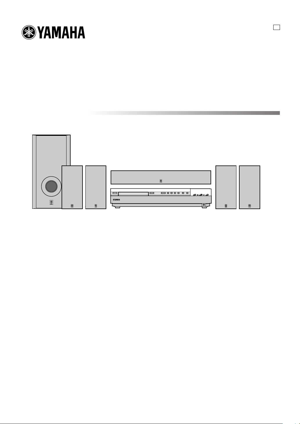
DVD HOME THEATER SOUND SYSTEM
SYSTEME HOME CINEMA DVD AUDIO/VIDEO
DVX-S100
DVX-S100: DVR-S100 + NX-S100S + NX-S100C + SW-S100
OWNER’S MANUAL
MODE D’EMPLOI
BEDIENUNGSANLEITUNG
BRUKSANVISNING
MANUALE DI ISTRUZIONI
MANUAL DE INSTRUCCIONES
GEBRUIKSAANWIJZING

CAUTION: READ THIS BEFORE OPERATING YOUR UNIT.
1 To assure the finest performance, please read this manual
carefully. Keep it in a safe place for future reference.
2 Install this sound system in a well ventilated, cool, dry, clean
place with at least 10 cm on the top, 10 cm on the left and
right, and 10 cm at the back of DVR-S100, and 20 cm on the
top, 10 cm on the left and right, and 10 cm at the back of
SW-S100 — away from direct sunlight, heat sources,
vibration, dust, moisture, and/or cold.
3 Locate this unit away from other electrical appliances,
motors, or transformers to avoid humming sounds. To
prevent fire or electrical shock, do not place this unit where
it may get exposed to dripping or splashing, and never put
any objects filled with liquids, such as vases, on the top of
the unit.
4 Do not expose this unit to sudden temperature changes from
cold to hot, and do not locate this unit in a environment with
high humidity (i.e. a room with a humidifier) to prevent
condensation inside this unit, which may cause an electrical
shock, fire, damage to this unit, and/or personal injury.
5 Avoid installing this unit in a place where foreign objects
and liquid might fall. It might cause a fire, damage to this
unit and/or personal injury. Do not place the following
objects on this unit:
– Other components, as they may cause damage and/or
discoloration on the surface of this unit.
– Burning objects (i.e. candles), as they may cause fire,
damage to this unit, and/or personal injury.
– Containers with liquid in them, as they may cause
electrical shock to the user and/or damage to this unit.
6 Do not cover this unit with a newspaper, tablecloth, curtain,
etc. in order not to obstruct heat radiation. If the temperature
inside this unit rises, it may cause fire, damage to this unit,
and/or personal injury.
7 Do not plug in this unit to a wall outlet until all connections
are complete.
8 Do not operate this unit upside-down. It may overheat,
possibly causing damage.
9 Do not use force on switches, knobs and/or cords.
10 When disconnecting the power cord from the wall outlet,
grasp the plug; do not pull the cord.
11 Do not clean this unit with chemical solvents; this might
damage the finish. Use a clean, dry cloth.
12 Only voltage specified on this unit must be used. Using this
unit with a higher voltage than specified is dangerous and
may cause fire, damage to this unit, and/or personal injury.
YAMAHA will not be held responsible for any damage
resulting from use of this unit with a voltage other than
specified.
13 To prevent damage by lightning, disconnect the power cord
from the wall outlet during an electrical storm.
14 Take care of this unit so that no foreign objects and/or liquid
drops inside this unit.
15 Do not attempt to modify or fix this unit. Contact qualified
YAMAHA service personnel when any service is needed.
The cabinet should never be opened for any reasons.
16 When not planning to use this unit for long periods of time
(i.e. vacation), disconnect the AC power plug from the wall
outlet.
17 Be sure to read the “TROUBLESHOOTING” section on
common operating errors before concluding that this unit is
faulty.
18 Before moving this unit, press STANDBY/ON to set this
unit in the standby mode, and disconnect the AC power plug
from the wall outlet.
19 VOLTAGE SELECTOR (General model only)
The VOLTAGE SELECTOR on the rear panel of this unit
must be set for your local main voltage BEFORE plugging
into the AC main supply.
Voltages are 220/240 V AC, 50 Hz.
This unit is not disconnected from the AC power source as
long as it is connected to the wall outlet, even if this unit
itself is turned off. This state is called the standby mode. In
this state, this unit is designed to consume a very small
quantity of power.
■ For U.K. customers
If the socket outlets in the home are not suitable for the plug
supplied with this appliance, it should be cut off and an
appropriate 3 pin plug fitted. For details, refer to the instructions
described below.
Note
• The plug severed from the mains lead must be destroyed, as a
plug with bared flexible cord is hazardous if engaged in a live
socket outlet.
■ Special Instructions for U.K.
Model
IMPORTANT
THE WIRES IN MAINS LEAD ARE COLOURED IN
ACCORDANCE WITH THE FOLLOWING CODE:
Blue: NEUTRAL
Brown: LIVE
As the colours of the wires in the mains lead of this apparatus
may not correspond with the coloured markings identifying
the terminals in your plug, proceed as follows:
The wire which is coloured BLUE must be connected to the
terminal which is marked with the letter N or coloured
BLACK. The wire which is coloured BROWN must be
connected to the terminal which is marked with the letter L or
coloured RED.
Making sure that neither core is connected to the earth
terminal of the three pin plug.
DANGER
Visible laser radiation when open. Avoid direct exposure to
beam.
When this unit is plugged to the wall outlet, do not place your
eyes close to the opening of the disc tray and other openings to
look into inside.
The laser component in this product is capable of emitting
radiation exceeding the limit for Class 1.
The name plate is located on the bottom of the unit.
CAUTION

CONTENTS
INTRODUCTION
FEATURES .......................................................................... 2
CHECKING THE ACCESSORIES ................................... 3
INSTALLING BATTERIES IN THE REMOTE
CONTROL ........................................................................... 3
CONTROLS AND FUNCTIONS ....................................... 4
Front panel ......................................................................... 4
Remote control (AMP mode) ............................................ 6
Front panel display (left) ................................................... 8
Front panel display (right) ................................................. 9
PREPARATION
PREPARATION STEPS ................................................... 10
SPEAKER SETUP ............................................................. 11
Speaker placement ........................................................... 11
Installing the speakers ..................................................... 12
CONNECTIONS ................................................................ 14
Connecting TV and audio/video components ................. 14
Connecting the antennas .................................................. 16
Connecting the speakers .................................................. 17
Connecting to an external amplifier ................................ 19
Connecting the AC power cord ........................................ 19
Turning on the power....................................................... 19
ADJUSTING SPEAKER OUTPUT LEVELS ................ 20
Using the test tone ........................................................... 20
USING BASIC FUNCTIONS
BASIC PLAYBACK .......................................................... 21
Basic operations ............................................................... 21
Selecting a sound field program ...................................... 23
RECORDING .................................................................... 28
PLAYING A DISC
DISC INFORMATION ..................................................... 29
Types of disc that this unit can play ................................ 29
Region management information .................................... 29
Notes about handling discs .............................................. 29
MP3 playback .................................................................. 30
REMOTE CONTROL (DVD MODE) ............................. 31
PLAYING A DISC ............................................................. 32
Basic operation ................................................................ 32
ON-SCREEN MENU ......................................................... 34
Operating menu bar ......................................................... 34
Icons for disc menu ......................................................... 35
Icons for player menu ...................................................... 36
USING MULTIPLE FUNCTIONS .................................. 38
Using a disc’s menu ......................................................... 38
Enhancing video quality
[U.S.A. and Canada models only] ................................... 38
DVD-Audio features........................................................ 39
Enhancing audio quality (DISC DIRECT) ...................... 40
Switching audio tracks, subtitles and angles ................... 41
All group play .................................................................. 42
Programmed play ............................................................. 42
Random play .................................................................... 43
Bookmarks ....................................................................... 44
Repeat play ...................................................................... 45
Repeat A-B ...................................................................... 46
SETUP MENU ................................................................... 47
Operating the setup menu ................................................ 47
Summary of settings ........................................................ 48
Ratings ............................................................................. 51
PCM down conversion..................................................... 51
Speaker settings ............................................................... 52
TUNING
TUNING ............................................................................. 54
Automatic and manual tuning ......................................... 54
Presetting stations ............................................................ 55
Tuning in to a preset station............................................. 56
Exchanging preset stations .............................................. 56
RECEIVING RDS STATIONS ......................................... 57
Description of RDS data .................................................. 57
Changing the RDS mode ................................................. 58
PTY SEEK function ........................................................ 58
REMOTE CONTROL FEATURES
OPERATING OTHER COMPONENTS USING THE
REMOTE CONTROL....................................................... 59
Setting the manufacturer code ......................................... 59
ADJUSTMENTS
SET MENU ......................................................................... 61
List of SET MENU items ................................................ 61
Adjusting the items on the SET MENU .......................... 61
1 SPEAKER SET (speaker mode settings) .................... 62
2 LFE LEVEL ................................................................ 63
3 SP DLY TIME (speaker delay time) ........................... 64
4 D. RANGE (dynamic range) ....................................... 64
5 L/R BALANCE (balance of the front left and right
speakers) ...................................................................... 64
6 HP TONE CTRL (headphone tone control) ................ 64
7 I/O ASSIGN (input assignment) ................................. 65
8 INPUT MODE (initial input mode) ............................ 65
9 SP/PRE OUT (output source settings) ......................... 65
ADJUSTING THE LEVEL OF THE EFFECT
SPEAKERS ........................................................................ 66
CHANGING THE PARAMETER SETTINGS FOR DSP
PROGRAMS ...................................................................... 67
Adjusting the delay time .................................................. 67
Adjusting the parameter settings for PRO LOGIC II
Music ............................................................................... 68
APPENDIX
TROUBLESHOOTING .................................................... 69
GLOSSARY ....................................................................... 74
SPECIFICATIONS ............................................................ 77
English
1

FEATURES
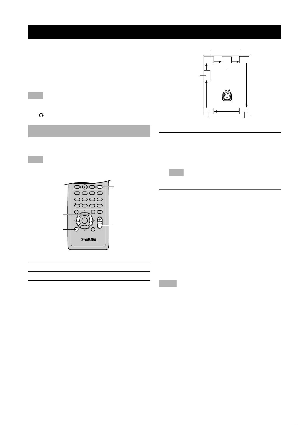
The DVX-S100 is the Home Theater Sound System that delivers a powerful and realistic sound experience like that
found in a movie theater just by combining the unit with the TV.
The newest DSP programs will enhance the power and realism of various sources, from movies to concerts, and
sporting events. Also, the Silent Cinema program allows you to enjoy the sound field even through the headphones.
Since the DVX-S100 consists of a DVD Audio/Video receiver, a center speaker, front speakers, rear speakers and a
subwoofer, you can enjoy stronger bass and surround effects as well as a good balance throughout the speakers.
Moreover, the One-touch connection of the speaker connectors designed exclusively for this unit allows you to easily
connect the speakers.
◆ Built-in 5-channel power amplifier
◆ DVD-AUDIO/VIDEO, CD, VCD, MP3, CD-R/
RW playback
◆ Dolby Pro Logic/Dolby Pro Logic II decoder
◆ Dolby Digital/Dolby Digital + Matrix 6.1
decoder
◆ DTS/DTS + Matrix 6.1 decoder
◆ Sophisticated FM/AM tuner
◆ CINEMA DSP: Combination of YAMAHA DSP
technology and Dolby Pro Logic, Dolby Digital
or DTS
■ About this manual
• y indicates a tip for your operation.
• Some operations can be performed by using the buttons
on either the main unit or the remote control. In this
case, the operations performed by using the remote
control are described in this manual.
• This manual is printed prior to production. Design and
specifications are subject to change in part for the
reason of the improvement in operativity ability, and
others. In this case, the product has priority.
• Some of the illustrations and names of the package
contents etc written in this manual may differ from the
actual products and the names written on the package
etc.
◆ Virtual CINEMA DSP
◆ SILENT CINEMA DSP
◆ Easy connection of the center speaker, front
speakers and rear speakers using special speaker
connectors designed exclusively for this unit
◆ Multi-function remote control which can also be
used for other audio/video components of certain
manufacturers
Manufactured under license from Dolby Laboratories.
“Dolby”, “Pro Logic”, and the double-D symbol are
trademarks of Dolby Laboratories.
“DTS” and “DTS Digital Surround” are registered
trademarks of Digital Theater Systems, Inc.
(U.S.A. and Canada models)
“DCDi” is a trademark of Faroudja, a division of Sage
Inc.
This product incorporates copyright protection
technology that is protected by method claims of certain
U.S. patents and other intellectual property rights owned
by Macrovision Corporation and other rights owners. Use
of this copyright protection technology must be
authorized by Macrovision Corporation, and is intended
for home and other limited viewing uses only unless
otherwise authorized by Macrovision Corporation.
Reverse engineering or disassembly is prohibited.
2
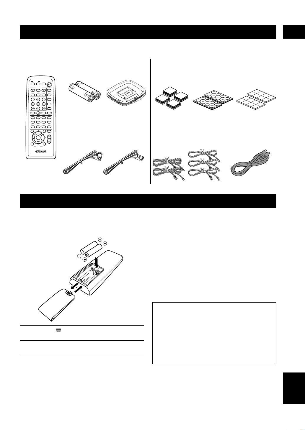
CHECKING THE ACCESSORIES
Check your package to make sure it contains the following items.
INTRODUCTION
DVR-S100
Remote control
POWER
POWER
TV
AV
SLEEP
TV MODE
INPUT
TUNER
CH
VOL
MD
MUTE CD–R
AUDIO
SUBTITLE
VCR
REC
VIDEO 2
VIDEO 1
CODE SET
SHIFT
DVDCDAMP
HALL2JAZZ
ROCK
ENTERTAINMENT
1
3
4
MARKER
SETUP
ANGLE
SPORTS6MONO MOVIE
MOVIE 1
MOVIE 2
5
7
8
PLAY MODE
REPEAT
A–B
/DTS
SELECT
MATRIX 6.1
STEREO
>
9
0
10
CANCEL
–
GROUP
PAGE
TOP MENU
MENU
LEVEL
SET MENU
MUTE
PRESET
FREQ/
ABCDE
RDS
CH
CH
ENTER
PRESET
B. BOOST
TEST
VOL
ON SCREEN
RETURN
PTY SEEK
MODE START
Batteries (x2)
(AA, R06, UM-3)
Indoor FM antenna
(U.S.A., Canada and
General models)
AM loop antenna
(Europe, U.K. and
Australia models)
INSTALLING BATTERIES IN THE REMOTE CONTROL
Insert the batteries in the correct direction by aligning the
+ and – marks on the batteries with the polarity markings
(+ and –) inside the battery compartment.
2
1
3
NX-SW100 (NX-S100S x4, NX-S100C, SW-S100)
Fasteners (4 sets)
for the center
speaker
Speaker cables
(for the rear speakers: 15m (x2),
for the front/center speaker:
5m (x3))
Pads
(2 sets: 16 pieces)
Non-skid pads
(2 sets: 16 pieces)
System connector
cable (5m x 1)
■ Notes on batteries
• Change all of the batteries if you notice a decrease in
the operating range of the remote control.
• Do not use old batteries together with new ones.
• Do not use different types of batteries (such as alkaline
and manganese batteries) together. Read the packaging
carefully as these different types of batteries may have
the same shape and color.
• If the batteries have leaked, dispose of them
immediately. Avoid touching the leaked material or
letting it come into contact with clothing, etc. Clean the
battery compartment thoroughly before installing new
batteries.
1 Press the part and slide off the battery
compartment cover.
2 Insert the two batteries (AA, R06, UM-3 type)
with + and – oriented properly.
3 Slide the cover back on so that it snaps into
place.
Preserving the manufacturer code
Replace batteries early before they become unusable.
The manufacturer code set by the user will be
preserved for about two minutes when batteries run
out or when they are removed. Note that the
manufacturer code setting may be lost if more than
two minutes elapses. Also, if you press any button on
the remote control accidentally while replacing
batteries, the manufacturer code will be lost.
English
3
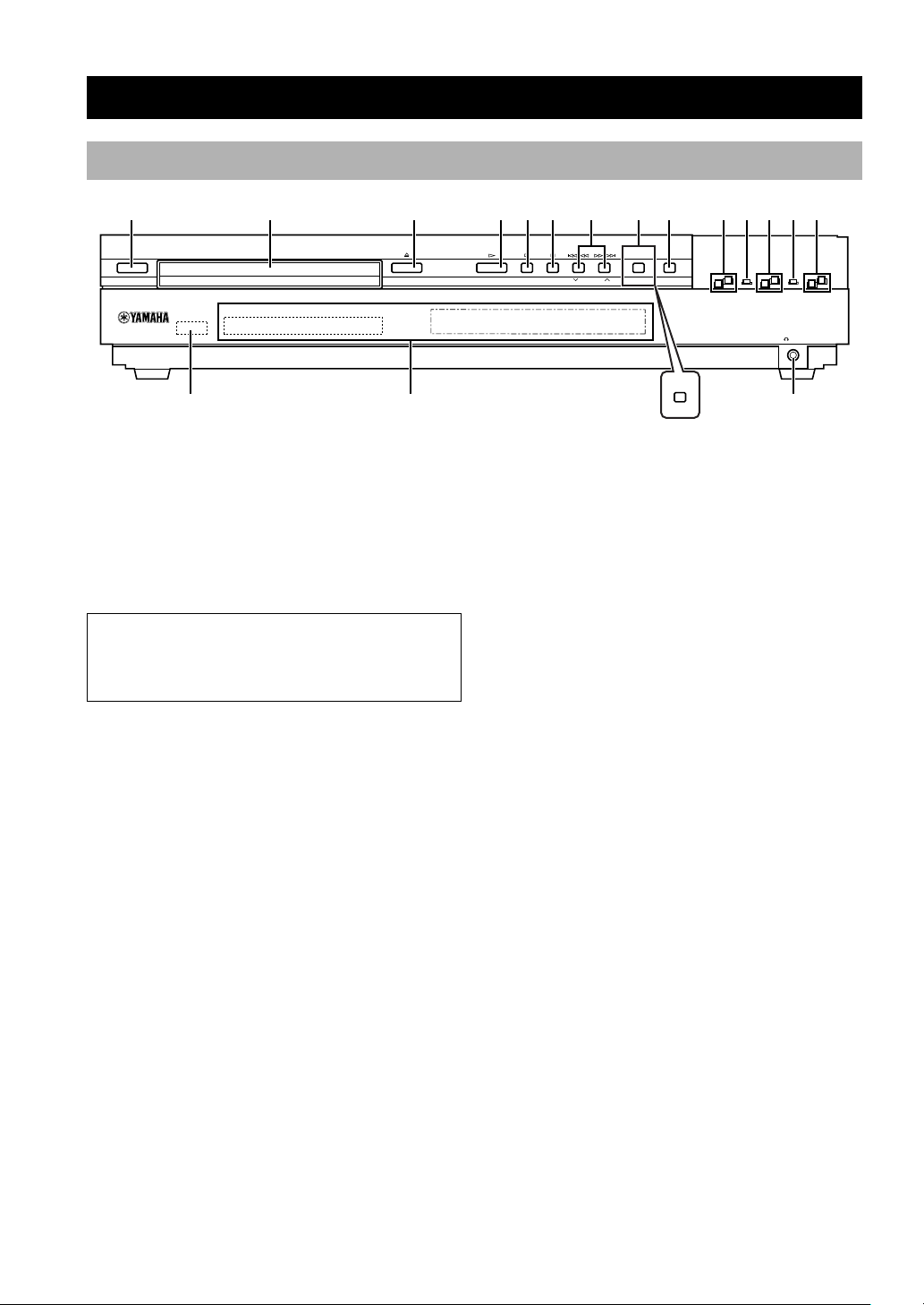
Front panel
CONTROLS AND FUNCTIONS
12 3456890qwer
STANDBY/ON
A/B/C/D/E
t
1 STANDBY/ON
Turns this unit on, or set it to the standby mode. When
you turn this unit on, you will hear a click and there will
be a 4 to 5-second delay before this unit can reproduce
sound.
Standby mode
In this mode, this unit will consume a small amount of
power in order to receive infrared-signals from the
remote control.
2 Disc tray
The disc you play is loaded on this tray.
3 v
Press to open and close the disc tray.
4 w
Press to start playback.
5 a (A/B/C/D/E)
(DVD mode)
Press to stop playback.
(Tuner mode)
Selects preset station groups A to E.
6 d (PRESET/BAND)
(DVD mode)
Press to pause.
(Tuner mode)
Switches the reception band between FM and AM and
also the mode between the tuning mode and the preset
mode.
y
7 t/e, r/y (d PRESET/TUNING /
PRESET/TUNING u)
(DVD mode)
Each time these buttons are pressed, the disc begins
playing from the beginning of the track you select. When
you keep pressing the buttons, the disc searches forward
or backward.
(Tuner mode)
Selects preset station numbers 1 to 8 when the colon (:)
appears in the front panel display.
Selects the tuning frequency when the colon (:) does not
appear.
8 PROGRESSIVE (MEMORY) (U.S.A. and
Canada models)
(DVD mode)
Switches between progressive video output and interlace
video output.
(Tuner mode)
Stores the current station in the memory.
MEMORY (U.K., Europe, Australia and
General models)
(Tuner mode)
Stores the current station in the memory.
9 DISC DIRECT (AUTO/MAN’L)
(DVD mode)
Changes the modes of DISC DIRECT function.
(Tuner mode)
Switches the tuning mode between automatic and manual.
7
PROGRESSIVE
DISC DIRECT
PRESET/BAND PRESET/TUNING MEMORY
(U.K., Europe, Australia and General models)
AUTO/MAN’L
MEMORY
SILENT
u
4

0 INPUT H/G
Selects the input source you want to listen to or watch.
q INPUT MODE
Sets the priority for the types of input signals (AUTO,
DTS, ANALOG) to receive when one component is
connected to two or more input jacks.
w DSP H/G
Selects the DSP program.
e STEREO
Switches between normal stereo and DSP effect
reproduction. When STEREO is selected, 2-channel
signals are directed to the front left and right speakers
without effect sounds.
r VOLUME +/–
Controls the output level of all audio channels.
This does not affect the recording (Rec) level.
t Remote control sensor
Receives signals from the remote control.
y Front panel display
Shows information about the operational status of this
unit.
CONTROLS AND FUNCTIONS
INTRODUCTION
SILENT
u
Allows you enjoy DSP effect for private listening with
headphones. When you connect headphones, no signals
are output to the speakers.
5
English
CONTROLS AND FUNCTIONS
Remote control (AMP mode)
This section explains the function of each button on the
remote control when you operate this unit as an amplifier,
not as a tuner or a DVD player. Make sure that the AMP
mode is selected before starting operation.
Refer to “REMOTE CONTROL (DVD MODE)” on page
31 for the details about the functions of the remote
control when you control this unit in the DVD mode.
Also, refer to “OPERATING OTHER COMPONENTS
USING THE REMOTE CONTROL” on pages 59 and 60
for the details about its functions when controlling other
components connected to this unit.
y
• The buttons on the remote control whose names are written in
purple are operation buttons when you operate this unit in the
AMP mode.
1
8
9
0
AMP
q
w
e
r
t
2
3
4
5
6
7
POWER
TV
AV
TV MODE
INPUT
CH
MUTE CD–R
SUBTITLE
REC
CODE SET
SHIFT
HALL2JAZZ
1
SETUP
SPORTS6MONO MOVIE
5
PLAY MODE
/DTS
SELECT
9
0
TOP MENU
LEVEL
SET MENU
PRESET
CH
ENTER
PRESET
B. BOOST
TEST
ON SCREEN
SLEEP
VOL
AUDIO
DVDCDAMP
ROCK
ANGLE
MOVIE 1
REPEAT
MATRIX 6.1
>
–
GROUP
MENU
CH
RETURN
3
7
10
ABCDE
POWER
TUNER
MD
VCR
VIDEO 2
VIDEO 1
ENTERTAINMENT
4
MARKER
MOVIE 2
8
A–B
STEREO
CANCEL
PAGE
MUTE
VOL
3 CODE SET
Used when setting up the manufacturer code.
4 DSP program buttons
Select DSP programs for the AMP position. Press a
button repeatedly to select a DSP program within that
group.
5 LEVEL
Selects the effect speaker channel to be adjusted.
6 Cursor buttons (j, i, u, d)/ENTER
Select SET MENU items and change the settings on the
SETUP menu etc.
7 TEST
Outputs the test tone to adjust the speaker levels.
8 SLEEP
Sets the sleep timer.
9 POWER (
)
Turns this unit on, or set it to the standby mode.
0 Input selector buttons/AMP
Select the input source and set the remote control to
operate the selected source component. Sets the remote
control to the AMP mode for controlling this unit.
q STEREO
Switches between normal stereo and DSP effect
reproduction. When STEREO is selected, 2-channel
signals are directed to the front left and right speakers
without effect sounds and all Dolby Digital and DTS
signals (except the LFE channel) are mixed down to the
front left and right speakers.
w MUTE
Mutes the sound. Press again to restore the audio output
to the previous volume level.
e SET MENU
Selects the SET MENU mode.
r VOL +/–
Increases or decreases the volume level.
(U.S.A. model)
1 Infrared window
Outputs infrared control signals. Aim this window at the
component you want to operate.
2 Basic operation buttons
Used to operate the components selected with input
selector buttons.
6
t B. BOOST
Turns BASS BOOST function on or off.

■ Using the remote control
Approximately 6 m (20 feet)
30° 30°
Handling the remote control
• Do not spill water or other liquids on the remote
control.
• Do not drop the remote control.
• Do not leave or store the remote control in the
following types of conditions:
– high humidity or temperature such as near a heater,
stove or bath;
– dusty places; or
– in places subject to extremely low temperatures.
CONTROLS AND FUNCTIONS
INTRODUCTION
7
English

CONTROLS AND FUNCTIONS
Front panel display (left)
This front panel display mainly displays the information related to the playback of discs.
1
PGM RND
–
GROUP TITLE TRACK CHAP D.MIX P.PCM MLT.CH
AB
2345
DVD V CD
VIDEO
AUDIO
68 9
7
1 Play mode indicators
PGM: Programmed play / RND: Random play /
: Repeat play / A-B : Repeat A-B
2 Mode type indicators
GROUP: Group mode / TITLE: Title mode /
TRACK: Track mode / CHAP: Chapter mode
3 D.MIX (Down Mix)
Lights up when the currently playing multi-channel audio
track is mixed down into 2-channel.
4 P.PCM (Packed PCM)
Lights up while a P.PCM signal is input.
5 MLT.CH (Multi Channel)
Lights up while a multi-channel signal is output.
888888888888
6 Disc type indicators
Indicates the type of disc. For example, DVD and AUDIO
lights up when playing a DVD-Audio disc.
7 w
Lights up during playback. Blinks while resume function
is working.
8 d
Lights up while playback is paused.
9 Multi-information display (left)
Shows various information such as title, chapter or track
number, elapsed playing time etc.
8

Front panel display (right)
12345
DIGITAL
PRO LOGIC
DSP
PCM
MATRIX
VIRTUAL
B. BOOST
/
88888888888888
SILENT
SP
PRE
DVD/CD VIDEO 1VIDEO 2 VCR
MOVIE THTR DTS
12
ENTERTAINMENT
r
6
MD/CD–R TUNER
DOLBY DIGITALPRO LOGIC
CONTROLS AND FUNCTIONS
(U.K. and Europe models only)
7890
STEREO
AUTO
PS PTY RT CT
PTY HOLD
SLEEP
dB
MUTE
ms
MEMORY
L
LFE
RL RC RR
TUNED
C R
iuytewq
o
INTRODUCTION
1 Decoder indicators
Lights up when the t, g,
PRO LOGIC
or
/
MATRIX are activated.
2 VIRTUAL indicator
Lights up in the virtual cinema DSP mode.
3 Headphones indicator
Lights up when headphones are connected.
4 SP/PRE indicator
The indicator of the item selected in “9 SP/PRE OUT” on
the SET MENU lights up. (But it does not light up when
headphones are connected.)
5 SILENT indicator
Lights up when headphones are connected while the
digital sound field processor is on.
6 Input source indicator
Shows the current input source with a cursor.
7 STEREO indicator
Lights up when this unit is receiving a strong signal for an
FM stereo broadcast while the “AUTO” indicator is lit.
8 AUTO indicator
Shows that this unit is in the automatic tuning mode.
9 TUNED indicator
Lights up when this unit is tuned to a station.
0 MEMORY indicator
Flashes to show a station can be stored.
q DSP indicator
Lights up when you select DSP programs.
w v indicator
Lights up when this unit is reproducing PCM (pulse code
modulation) digital audio signals.
e B. BOOST indicator
Lights up when BASS BOOST is ON. (But it does not
light up when headphones are connected.)
r DSP program indicators
The name of the selected DSP program lights up when
the ENTERTAINMENT, MOVIE THEATER 1, MOVIE
THEATER 2 or V/DTS SURROUND DSP program is
selected.
t Multi-information display (right)
Shows the current DSP program name and other
information when adjusting or changing settings.
y SLEEP indicator
Lights up while the sleep timer is on.
u MUTE indicator
Flashes while the MUTE function is on.
i Input channel indicator
Indicates the channel components of input signals being
received.
o RDS indicator (U.K. and Europe models)
The name(s) of the RDS data offered by the currently
received RDS station light(s) up.
PTY HOLD indicator lights up while searching for
stations in the PTY SEEK mode.
9
English
PREPARATION STEPS
In order to enjoy sound and video images with this sound
system, follow the procedures as described below. See
each page for details.
Installing batteries in the remote control (P.3)
Speaker setup (P.11)
• Speaker placement (P.11)
• Installing the speakers (P.12)
Connections (P.14 – 19)
• Connecting TV and audio/video components (P.14)
• Connecting the antennas (P.16)
• Connecting the speakers (P.17)
• Connecting the AC power cord (P.19)
• Turning on the power (P.19)
Adjusting speaker output levels (P.20)
Before connecting components
• Do not connect this unit or other components to the
mains power until all connections between the
components have been completed.
• Be sure all connections are made correctly, that is to
say, L (left) to L, R (right) to R, “+” to “+” and “–” to
“–”. Some components require different connection
methods and have different jack names. Refer to the
operation instructions for each component to be
connected to this unit.
• Insert the plugs properly. The speakers may not output
any sound or may output noise if they are not inserted
properly.
• The name of jack corresponds to input selector.
• The VOLTAGE SELECTOR on the rear panel of this
unit must be set for your local main voltage BEFORE
plugging into the AC main supply. Voltages are
220/240 V AC, 50 Hz. (General model)
VOLTAGE SELECTOR
240V 220V
VOLTAGE SELECTOR
(General model)
After connecting components
• Check them again to make sure they are correct.
10

SPEAKER SETUP
This unit has been designed to provide the best soundfield quality with a 5-speaker system, using front left and
right speakers, rear left and right speakers and a center
speaker.
The front speakers are used for the main source sound
plus effect sounds. The rear speakers are used for effect
and surround sounds. The center speaker is for the center
sounds (dialog, vocals, etc.).
Notes
• If you do not use any of effect speakers (rear and/or center),
change the settings of SPEAKER SET items at the SET MENU
(p.62) to designate the signals to other terminals you connect
speakers to.
• If you use speakers (with different tonal qualities) instead of
the included speakers, the tone of a moving human voice and
other types of sound may not shift smoothly. We recommend
that you use speakers from the same manufacturer or speakers
with the same tonal quality.
Speaker placement
Refer to the following diagram when you place the
speakers.
Center speaker Front speaker (R)
Rear speaker (R)
1.8 m (6 feet)
Front speaker (L)
Subwoofer
Front speakers
Place the front left and right speakers an equal distance
from the ideal listening position. The distance between
each speaker and each side of the video monitor should
also be the same.
Center speaker
Align the front face of the center speaker with the front
face of your video monitor. Place the speaker as close to
the monitor as possible (such as directly over or under the
monitor) and centrally between the front speakers.
Rear speakers
Place these speakers behind your listening position,
facing slightly inwards, nearly 1.8 m (6 feet) above the
floor.
Subwoofer
The position of the subwoofer is not so critical, because
low bass sounds are not highly directional. But it is better
to place the subwoofer near the front speakers. Turn it
slightly toward the center of the room to reduce wall
reflections.
Note
• Although the speaker system in this unit is magnetically
shielded, it may still affect the color on the television monitor
when using this unit near the television. Adjust the relative
positions of this unit and the television if this happens.
Rear speaker (L)
PREPARATION
11
English
SPEAKER SETUP
Installing the speakers
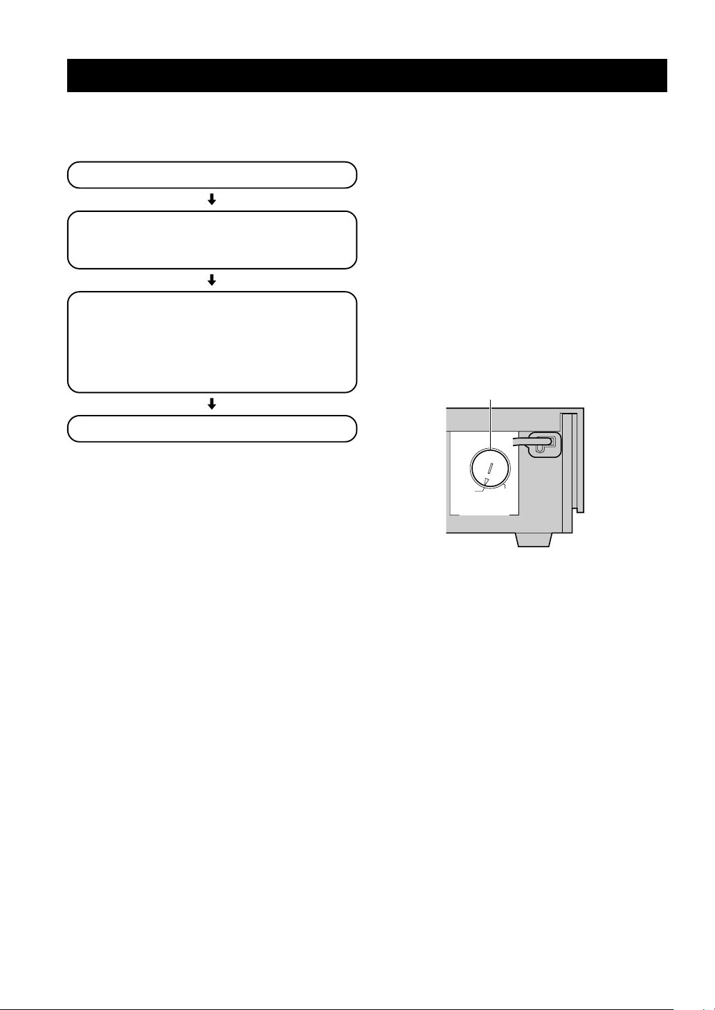
■ Placing the center speaker
Place the speaker on TV whose top is flat or on the floor
under the TV or inside the TV rack so that it is stabilized.
When placing the speaker on top of the TV, to prevent the
speaker from falling down, put the provided fasteners at
four points on the bottom of the speaker and the top of the
TV.
Fastener
Peel off the
seal
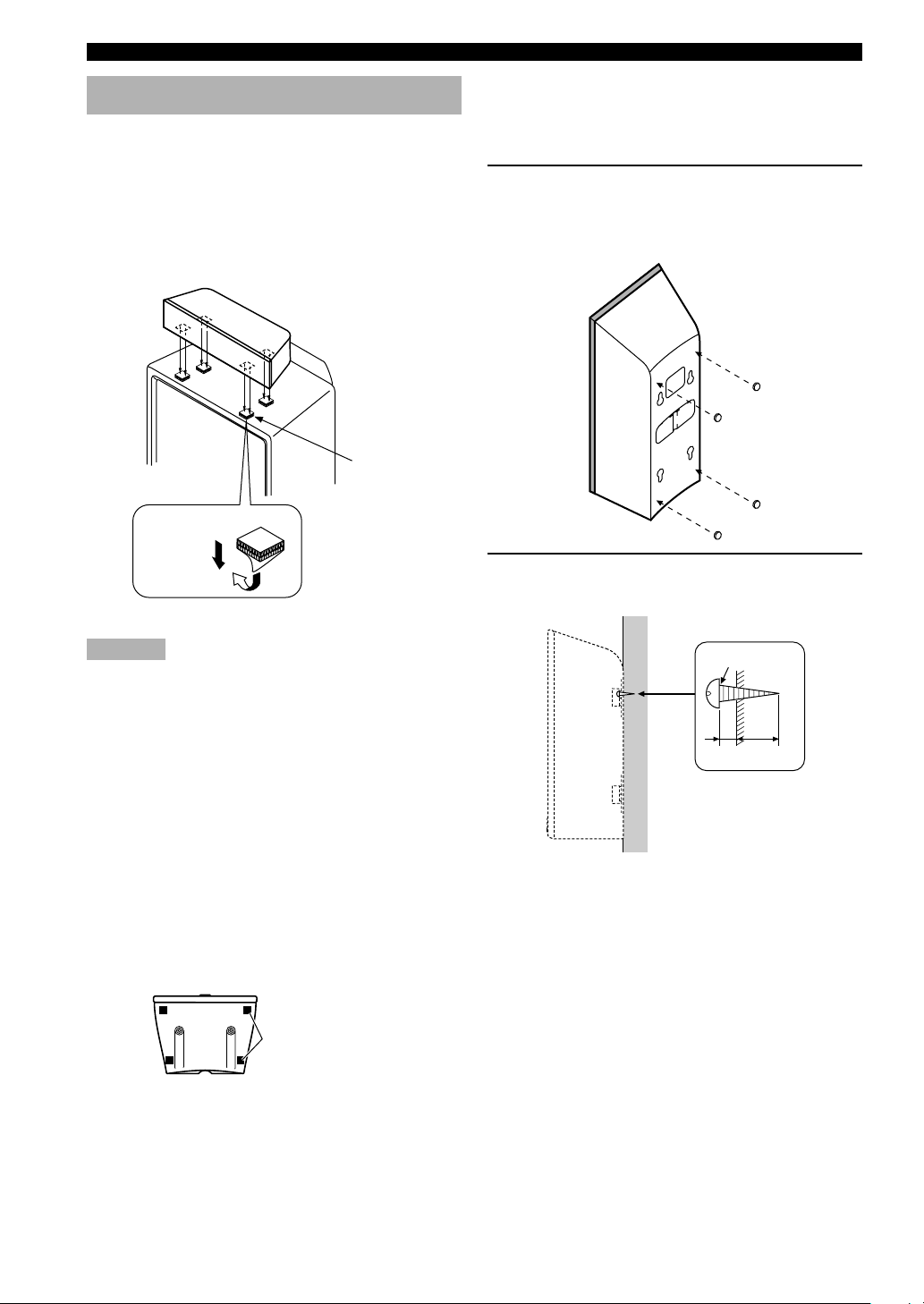
■ Mounting the front and rear
speakers
When mounting the front and rear speakers on a wall, use
the holes on the speakers’ back panels.
1 Put the provided pads at the four corners on
the rear of the front and rear speakers to
prevent the front and rear speakers from
moving by vibrations.
2 Fasten screws into a firm wall or wall
support as shown below.
Cautions
• Do not place the speaker on top of the TV whose area is
smaller than the bottom area of the speaker. If placed, the
speaker may drop out causing an injury to you.
• Do not place the speaker on top of the TV with an inclination.
• Do not touch the adhesive surface after peeling off the seal as
this will weaken its adhesive strength.
• Thoroughly wipe clean the surface where the fastener is to be
applied. Note that adhesive strength is weakened if the surface
is dirty, oily or wet and that this may cause the center speaker
to drop.
■ Placing the front and rear
speakers
When placing the front and rear speakers on a flat
surface, attach the included non-skid pads to the corners
on the bottom of the speakers as shown below. This
prevents the speakers from sliding around.
Non-skid pads
Diam. 3.5 to 4 mm
Min.
20 mm
6 mm
Tapping screw
(Available at the
hardware store)
12
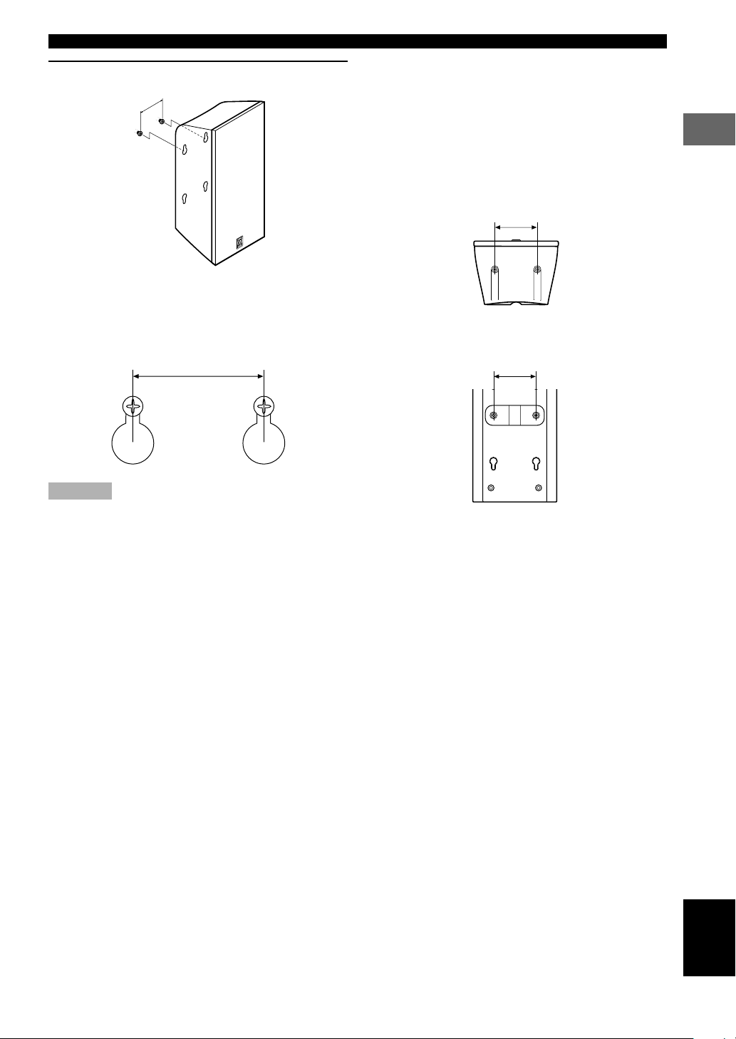
SPEAKER SETUP
3 Hang the holes on the protruding screws.
60 mm
• Make sure that the screws are securely caught by
the narrow parts of the holes.
• You can use the lower holes on the rear of the
front/rear speakers.
60 mm
■ If you want to mount a speaker
on a commercially available
speaker stand (for the front/rear
speakers)
The screw holes (at an interval of 60 mm) on the bottom
and the rear of the speaker can be used to mount the
speaker on a speaker stand.
* Those screw holes can be used with M4 screws only.
60 mm
Front/rear speaker
(bottom)
60 mm
PREPARATION
Cautions
• Each speaker weighs 1.1 kg (2 lbs. 6 oz.). Do not mount them
on thin plywood or a wall with soft surface material. If
mounted, the screws may come out of the flimsy surface and
the speakers may fall. This damages the speakers or causes
personal injury.
• Do not install the speakers to a wall with nails, adhesives, or
any other unstable hardware. Long-term use and vibrations
may cause them to fall.
• To avoid accidents resulting from tripping over loose speaker
cables, fix them to the wall.
• Select a proper position on the wall to mount the speaker so
that no one will injure his/her head or face.
Front/rear speaker
(rear)
13
English

CONNECTIONS
Connecting TV and audio/video components
■ Types of video jacks
PR PB Y
321
1 COMPONENT VIDEO jacks (U.S.A., Canada,
Australia and General models)
Transmit color difference (PB/CB, PR/CR) and luminance
separately and provide the best quality picture.
2 VIDEO jack
Conventional composite video signal.
3 S VIDEO jack
Transmits color and luminance separately and achieves
high-quality color reproduction.
Notes
• Each type of video jack works independently. Signals input
through the composite video and S video jacks are only output
through the corresponding composite video and S video jacks.
• When you connect this unit to a video monitor, a video
component and a recording component, connect the same types
of jack, for example, the video jack on this unit to the video
jack on the video component.
• The description of the component video jacks may differ
depending on the component (e.g. Y, CB, CR/Y, PB, PR/Y, B-Y,
R-Y etc.). When using these jacks, refer also to the operation
instructions for the component being connected.
• Do not connect this unit to a video monitor through a video
cassette recorder. If you do so, the picture may not be played
back properly due to the copyright protection technology
incorporated in this unit.
• When progressive output (p.38) is selected in the DVD mode,
video signals are only output from the component video jacks.
■ Types of audio jacks
L
R
1 23
1 COAXIAL jack
Connects a coaxial pin cable and provides the better
quality sound than analog audio jacks.
2 OPTICAL jack
Connects an optical fiber cable and provides the better
quality sound than analog audio jacks.
3 Analog audio jacks
Connect an audio pin cable.
y
• 1 and 2 are digital jacks.
• You can use the digital jacks to input PCM, Dolby Digital and
DTS bitstreams.
• All digital input jacks are acceptable for 96-kHz sampling
digital signals.
Notes
• DIGITAL OUTPUT jack and analog OUT (Rec) jacks are
independent. Only digital signals are output from DIGITAL
OUTPUT jack and analog signals from OUT (Rec) jacks.
• The OPTICAL jacks on this unit conform to the EIA standard.
If you use an optical cable that does not conform to this
standard, this unit may not function properly.
• Once you have connected a recording component to this unit,
keep its power turned on while using this unit. If the power is
off, this unit may distort the sound from other components.
Anti-dust cap
Remove the cap covering the OPTICAL jacks when
connecting an optical cable. Safely store the cap and
always re-insert it in the terminal when the terminal is not
in use. (This cap prevents the entrance of dust.)
14
Anti-dust cap
CONNECTIONS
FM ANT
75ΩUNBAL.
GND – AM ANT
■ The connection example
Use a commercially available cable specified for connecting each type of jacks.
For Audio component
Audio pin cable
Coaxial cable
Optical cable
For Video Component
Video pin cable
S Video cable
Component video cable
(U.S.A., Canada, Australia and General
models)
For A/V component
Audio/Video cable
The connection example shown below is just an example. Connect in accordance with the components you have.
y
• The solid lines indicate the output from this unit and the dotted lines indicate the input to this unit.
PREPARATION
INPUT
S VIDEO
S Video cable
VIDEO
Video pin cable
COMPONENT
VIDEO
Component video cable
PR/CR
(U.S.A., Canada, Australia and General
PB/CB
models)
Y
Video monitor
Coaxial cable
Audio pin cable
Optical cable
L
R
INPUT
OPTICAL
AUDIO
OUTPUT
COAXIAL
AUDIO
CD recorder or MD recorder
MD/CD-R VIDEO 1
[B]
COAXIAL
IN
DIGITAL
L
R
Audio pin cable
OPTICAL
L
R
INPUT
S VIDEO
VIDEO
AUDIO
L
R
VCR
S Video cable
Audio/Video
OUTPUT
S VIDEO
VIDEO
AUDIO
cable
S Video cable
OUT OUT
MONITOR
VCR
MD/CD-R FRONT CENTER
ANALOG
OUT OUT
IN IN IN
MONITOR
VIDEO 1 VIDEO 2 VCR
REAR
SUBWOOFER
6CH PREOUT
S Video cable
Optical cable
Audio/Video cable
SYSTEM
CONNECTOR
TO SW-S100
S VIDEO
MARK
Audio/Video cable
(U.S.A. model)
OUTPUT
S VIDEO
OPTICAL
VIDEO
AUDIO
L
R
English
PRPBY
COMPONENT VIDEO OUT
MD/CD-R
[A]
OPTICAL
IN
OUT
VIDEO
IN
IN IN
VIDEO 1 VIDEO 2
L
R
IN IN IN INOUT OUT
TV/digital TV/cable TV
15
CONNECTIONS
Connecting the antennas
Both AM and FM indoor antennas are included with this
unit. In general, these antennas should provide sufficient
signal strength.
Connect each antenna correctly to the designated
terminals.
■ Connecting indoor FM antenna
Connect the included indoor FM antenna to the FM ANT
terminal.
Indoor FM antenna
(included)
AM loop antenna
(included)
FM ANT GND – AM ANT
75ΩUNBAL.
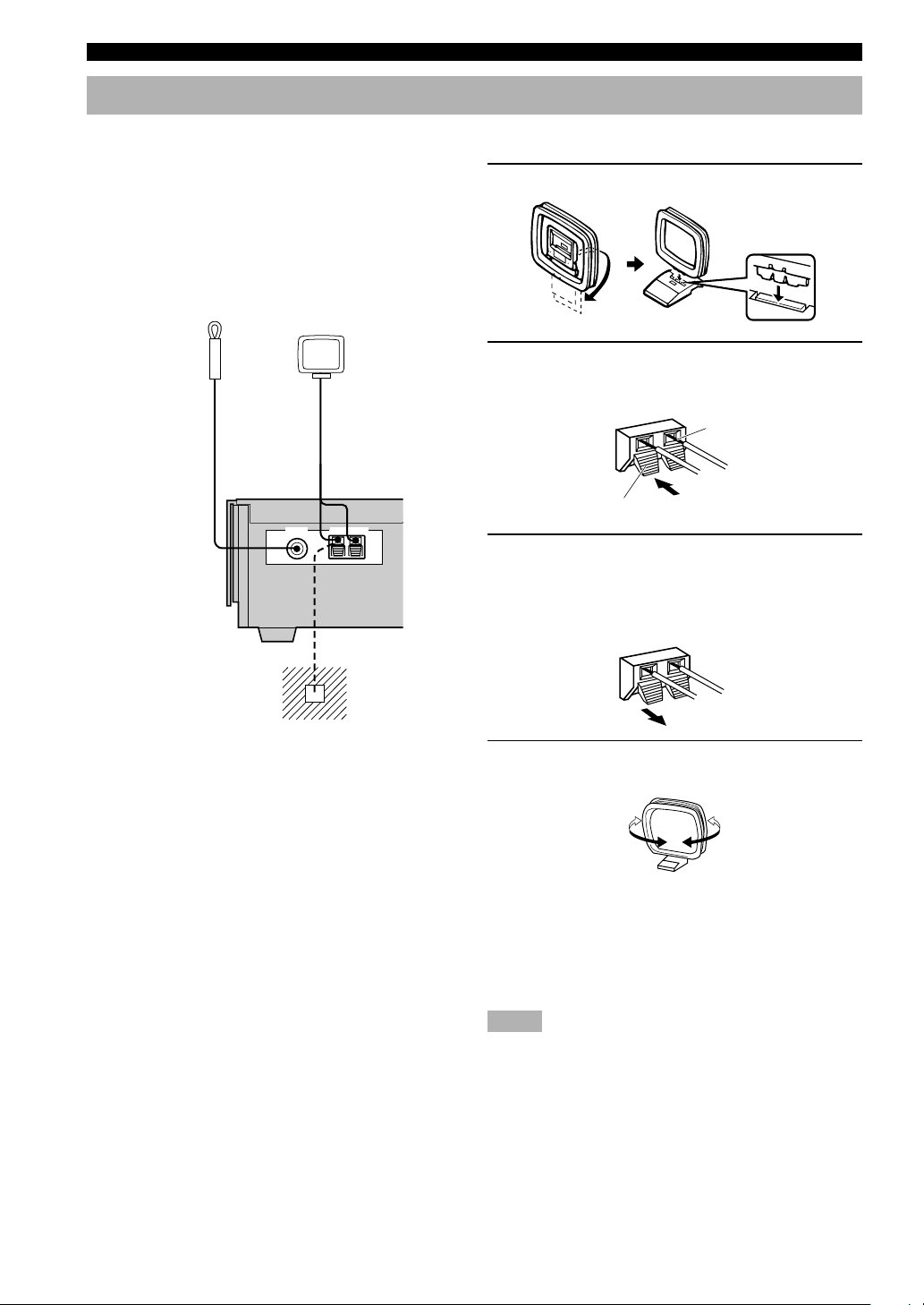
■ Connecting the AM loop antenna
1 Set up the AM loop antenna, then connect it.
2 Press and hold the tab to insert the AM loop
antenna lead wires into the AM ANT and
GND terminals.
Bare wire
Tab
3 Release the tab. (The tab will return to its
original position when you release your
finger.)
Once connected, pull the wires gently to check that
they are connected securely.
Ground (GND terminal)
For maximum safety and
minimum interference, connect
the antenna GND terminal to a
good earth ground. A good earth
ground is a metal stake driven into
moist earth.
4 Orient the AM loop antenna for the best
reception.
y
• A properly installed outdoor antenna provides clearer reception
than an indoor one. If you experience poor reception quality, an
outdoor antenna may improve the quality. Consult the nearest
authorized YAMAHA dealer or service center about the
outdoor antennas.
Notes
• The AM loop antenna should be placed away from this unit.
• The AM loop antenna should always be connected, even if an
outdoor AM antenna is connected to this unit.
16
CONNECTIONS
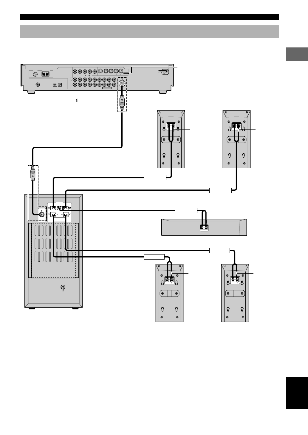
Connecting the speakers
Connect the included speakers to the DVD AUDIO/VIDEO receiver (DVR-S100) using the included speaker cables and
system connector cables as shown below.
DVD Audio/Video receiver (DVR-S100)
IN IN IN
OUT OUT
FM ANT
GND – AM ANT
75ΩUNBAL.
MD/CD-R
[B]
COAXIAL
IN
[A]
OPTICALINOPTICAL
DIGITAL
MD/CD-RVIDEO 1
OUT
*1 Insert the plug with its
System connector cable
VIDEO
IN
IN IN
OUT OUT
L
R
VIDEO 1 VIDEO 2
MONITOR
VCR
IN IN IN INOUT OUT
ANALOG
mark facing up.
MONITOR
VIDEO 1 VIDEO 2 VCR
REAR
MD/CD-R FRONT CENTER
6CH PREOUT
*1
SUBWOOFER
SYSTEM
CONNECTOR
TO SW-S100
S VIDEO
MARK
Front speaker (R)
(NX-S100S)
As this terminal is used for testing at the
factory, do not connect any equipment to this
terminal.
Front speaker (L)
(NX-S100S)
(RED) (WHITE)
PREPARATION
*1
R L
(RED)
MARK
R
(GRAY)
DO NOT CONNECT THIS UNIT TO
SYSTEM
SPEAKERS OTHER THAN NX-S100C
CONNECTOR
AND NX-S100S.
TO DVR-S100
Subwoofer (SW-S100)
SPEAKERS
CENTERFRONT FRONT
(GREEN)
REAR
(SURROUND)
Speaker cable (RED)
Speaker cable (WHITE)
Speaker cable (GREEN)
(WHITE)
L
(BLUE)
Speaker cable (BLUE)
Speaker cable (GRAY)
FRONT R
REAR R
Rear speaker (R)
(NX-S100S)
FRONT L
CENTER
Center speaker (NX-S100C)
REAR L
(GRAY) (BLUE)
Rear speaker (L)
(NX-S100S)
(GREEN)
17
English
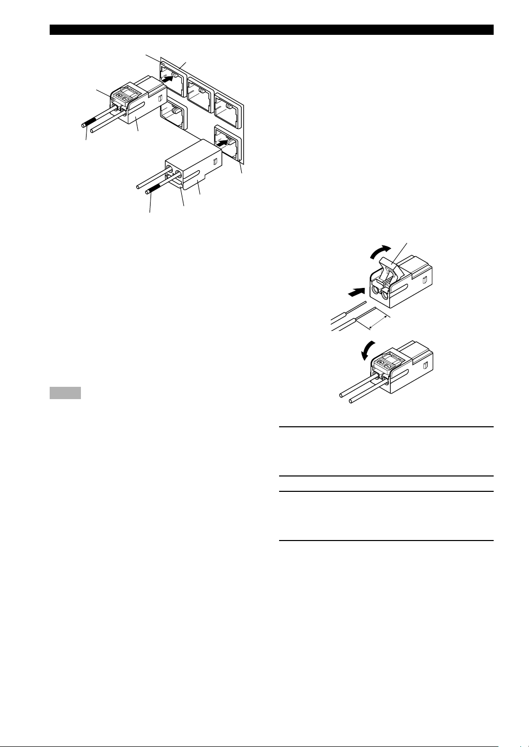
CONNECTIONS
(RED)
(RED)
Connector
Color tube
(RED)
Color tube
(BLUE)
The back of the
Subwoofer
(BLUE)
Connector
(BLUE)
y
• The connector of the included speaker cable and the terminal of
the subwoofer are classified by color. Connect the same colors.
• The label of the speaker is attached to each speaker cable.
Connect the speakers in accordance with the labels.
• Connect the color tube of the speaker cable to the plus (+) side
of each speaker. If the polarity of the speaker connections is
incorrect, the sound will be unnatural and lack bass.
• A cover is attached to the end of the speaker cable. Connect the
speakers after removing the cover.
• Make sure that the plugs of the system connector cable and the
connectors of the speaker cables are inserted correctly before
inserting them.
Notes
• Do not let the bare speaker wires touch each other or any metal
part of this unit. This could damage this unit and/or the
speakers.
• Do not insert the plug or connector forcibly. Doing so may
damage the plug, connector or terminal.
• Do not scratch, forcibly bend, or pull the system connector or
speaker cable as this may damage the cable, causing loss of
audio output, and may possibly result in a fire or electric shock.
Take particular care in making sure that the cable is not
squashed by a rack or caster.
• Before disconnecting or connecting the system connector
cable, disconnect the power supply cord of the subwoofer and
DVD audio/video receiver.
■ Using commercially available
speakers and speaker cables
You can use commercially available speaker cables and
speakers except for a subwoofer. If you use them, note the
following.
• Use the speaker whose impedance is 6Ω or higher.
When using the speaker whose impedance is lower than
6Ω, the protection circuit may start working or this unit
may be damaged.
• Use magnetically shielded speakers. If this type of
speakers still creates the interference with the monitor,
place the speakers away from the monitor.
• Use the speaker cable that is as thick as the included
cable. Too thick cables cannot be used.
Exchanging the speaker cables
2
Tab
3
1
15 mm
4
1 Remove approximately 15 mm (9/16”) of
insulation from each of the speaker cables.
Twist the exposed wires of the cable together to
prevent short circuits.
2 Open the tab.
3 Pull the inserted bare wire of the speaker
cable from the connector and insert the bare
wire of the commercially available speaker
cable.
4 Return the tab to secure the wire.
18
CONNECTIONS
STANDBY/ON
TV
CH
INPUT
TUNER
MUTE CD–R
VCR
VIDEO 2
VIDEO 1
MD
AV
SLEEP
POWER
TV MODE
POWER
VOL
REC
AUDIO
SUBTITLE
SHIFT
CODE SET
HALL
JAZZ
ROCK
ENTERTAINMENT
DVDCDAMP
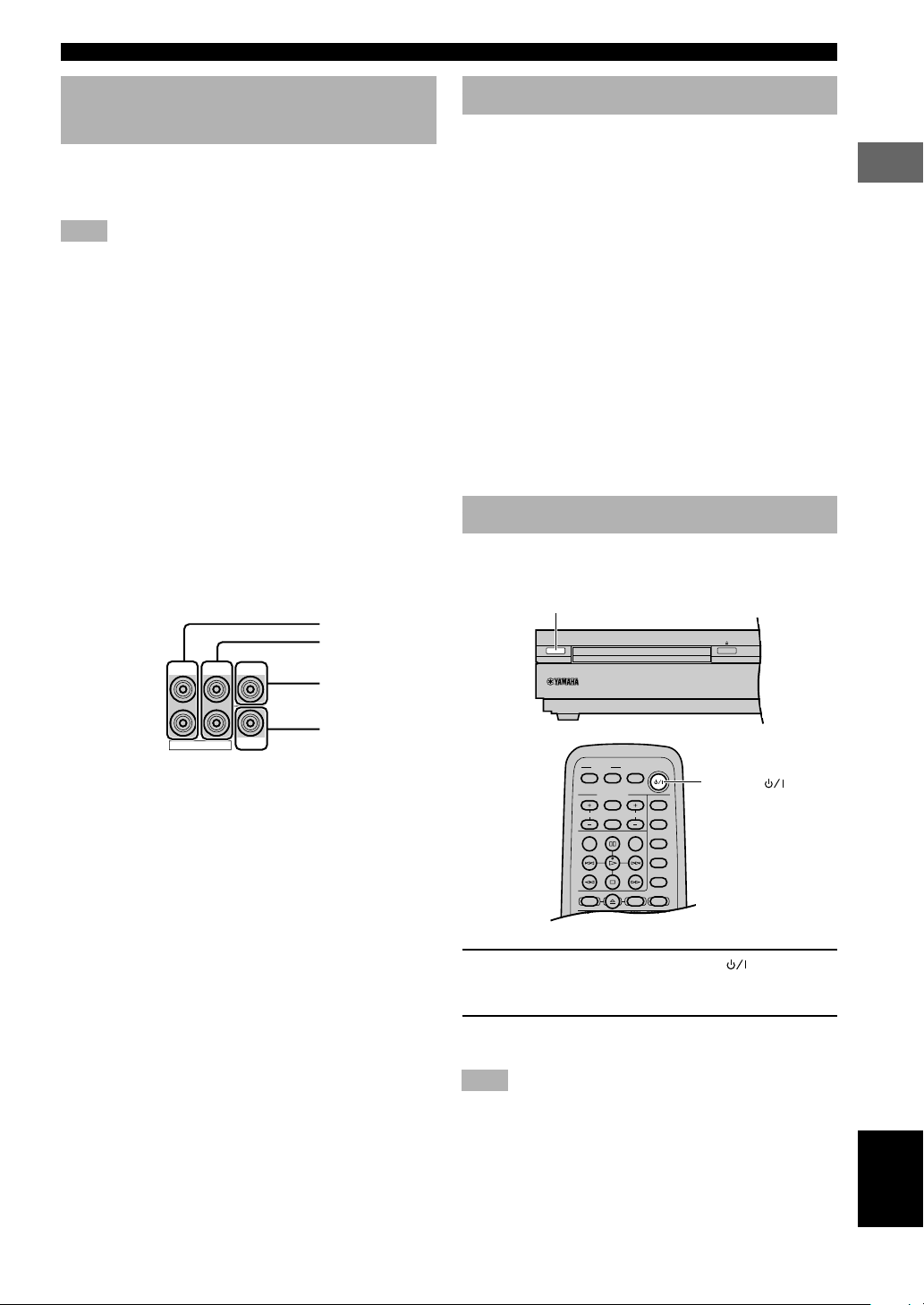
Connecting to an external amplifier
If you want to increase the power output to the speakers,
or want to use another amplifier, connect an external
amplifier to the 6CH PREOUT jacks as follows.
Note
• When you have connected this unit to an external amplifier,
select PRE in “9 SP/PRE OUT” on the SET MENU. (See page
65.)
1 FRONT jacks
Front channel line output jacks.
2 REAR jacks
Rear channel line output jacks.
3 CENTER jack
Center channel line output jack.
4 SUBWOOFER jack
Low bass signals distributed from the front, center and/or
rear channels are directed to this jack if they are assigned
to this jack. (The cut-off frequency of this jack is 90 Hz.)
The LFE (low-frequency effect) signals generated when
Dolby Digital or DTS is decoded are also directed if they
are assigned to this jack.
1
2
FRONT CENTER
REAR
3
Connecting the AC power cord
Plug in this unit to the wall outlet.
■ Memory back-up
The memory back-up circuit prevents the stored data from
being lost when the power cord is disconnected from the
AC outlet, or the power supply is temporarily cut due to
power failure. However, if the unit is turned off for more
than one week, the stored setting will be cleared. If so, set
the setting again.
• Volume level
• Input source
• Speaker output level (center, rear L/R and subwoofer)
• Sleep timer
• Parameter
• Delay time
• Set menu
• Disc direct
• Preset station
Turning on the power
When all connections are complete, turn on the power of
this unit.
STANDBY/ON
PREPARATION
6CH PREOUT
SUBWOOFER
4
y
• The adjustments made in the following settings have an effect
on the signals output from the 6CH PREOUT jacks.
– BASS BOOST settings
– Speaker settings
– DSP programs
POWER ( )
1 Press STANDBY/ON (POWER ( ) on the
remote control) to turn on the power of this
unit.
2 Turn on the video monitor connected to this
unit.
Note
• When you use only some of the included 6 speakers or when
using commercially available speakers, adjust speaker mode
settings soon after turning the power on. See “1 SPEAKER
SET (speaker mode settings)” on page 62 for details.
19
English
ADJUSTING SPEAKER OUTPUT LEVELS
VIDEO 1
SHIFT
CODE SET
1
HALL2JAZZ
SETUP
3
ROCK
ANGLE
4
ENTERTAINMENT
MARKER
5
SPORTS6MONO MOVIE
PLAY MODE
7
MOVIE 1
REPEAT
8
MOVIE 2
A–B
DVDCDAMP
9
/DTS
TOP MENU
LEVEL
MENU
SET MENU
TEST
ON SCREEN
B. BOOST
RETURN
0
SELECT
>
–
10
MATRIX 6.1
GROUP
CANCEL
STEREO
PAGE
MUTE
VOL
ABCDE
ENTER
PRESET
PRESET
CHCH
This section explains how to adjust speaker output levels
using the test tone generator. When this adjustment is
complete, the output level heard at the listening position
should be the same from each speaker. This is important
for best performance of the digital sound field processor,
and the various decoders (Dolby Digital, Dolby Pro
Logic, Dolby Pro Logic II and DTS).
Note
• Since this unit cannot enter the test mode while headphones are
connected to this unit, be sure to unplug the headphones from
the SILENT jack when using the test tone.
Using the test tone
Use the test tone to balance the output levels of the
speakers.
Note
• The adjustment of each speaker output level should be made at
your listening position using the remote control.
AMP
j, i
TEST
(U.S.A. model)
VOL + / –
1 Press AMP.
2 Press TEST to output the test tone.
3 Press VOL +/– to adjust the volume of this
unit so you can hear the test tone.
The test tone is heard (in order) from the LEFT
(front left speaker), CENTER (center speaker),
RIGHT (front right speaker), R SUR. (rear right
speaker), L SUR. (rear left speaker), and the
SUBWOOFER (subwoofer). The tone is produced
for about 2 seconds from each speaker.
SUBWOOFER
LEFT
CENTER
RIGHT
L SUR. R SUR.
4 Adjust the level of the effect speakers using
j/i so that it matches the level of the front
speakers.
While adjusting, the test tone is heard from the
selected speaker.
Note
• To adjust the level of the front speakers, use VOL +/– on
the remote control.
5 When adjustment is complete, press TEST to
stop the test tone.
y
• It is not necessary to readjust the speaker levels once they are
set (as long as you do not change the speakers). You can enjoy
listening to or watching the input source at the desired volume
simply by pressing VOL +/– on the remote control.
• If the output level of the effect speakers (center, rear left, and
rear right) cannot be increased enough to match the level of the
front speakers, set “1E F. Level” on SET MENU to –10 dB (see
page 63). This setting decreases the front speaker output level
to about one-third of the normal level. After you have set “1E F.
Level” on the SET MENU to –10 dB, adjust the levels for the
center and rear speakers again.
Notes
• If “1A CENTER” on the SET MENU is set to NON and the
center speaker is not connected, the center channel sound is
automatically output from the front left and right speakers.
• If “1C REAR LR” on the SET MENU is set to NON, the
output level of the rear left and right speakers cannot be
adjusted in step 4. The test tone will be circulated skipping the
rear right and left speakers.
• If “1D BASS” on the SET MENU is set to FRONT, the test
tone will be circulated skipping the subwoofer.
20
BASIC PLAYBACK
TV
CH
INPUT
TUNER
MUTE CD–R
VCR
VIDEO 2
VIDEO 1
MD
AV
SLEEP
POWER
TV MODE
POWER
VOL
REC
AUDIO
SUBTITLE
SHIFT
CODE SET
1
HALL2JAZZ
SETUP
3
ROCK
ANGLE
4
ENTERTAINMENT
MARKER
5
SPORTS6MONO MOVIE
PLAY MODE
7
MOVIE 1
REPEAT
8
MOVIE 2
A–B
DVDCDAMP
9
/DTS
TOP MENU
LEVEL
MENU
SET MENU
TEST
ON SCREEN
B. BOOST
RETURN
0
SELECT
>
–
10
MATRIX 6.1
GROUP
CANCEL
STEREO
PAGE
MUTE
VOL
ABCDE
ENTER
PRESET
CH
PRESET
CH
Basic operations
You can play the software loaded on the audio and video
components connected to this unit.
SLEEP
DSP program
buttons
B.BOOST
(U.S.A. model)
POWER ( )
Input selector
buttons
MUTE
VOL + / –
Indication on the front panel display (example):
SP
VIDEO 1
VIDEO 1 AUTO
Selected input source Input mode
5 Adjust the volume to the desired level.
The volume level is displayed digitally.
Example: –70 dB
Control range: VOLUME MUTE (minimum) to
0 dB (maximum)
Note
• If you have connected a recording component to the VCR
OUT, or MD/CD-R OUT jacks, and you notice distortion or
low volume during playback of other components, try turning
the recording component on.
■ Enhancing the bass tones
Press B. BOOST.
•“Bass Boost ON” appears in the display.
• This function enhances the bass tones of the
subwoofer by increasing the level of the low-range
frequencies.
• To cancel B. BOOST mode, press B. BOOST
again.
y
• The B. BOOST mode does not function when the headphones
are connected.
Note
• If a thudding noise is heard from the subwoofer when this
function is turned on, lower the subwoofer level. Otherwise, the
subwoofer may be damaged due to an excessive input level of
low-bass signal.
■ To mute the sound
USING BASIC FUNCTIONS
1 Press POWER ( ) to turn on the power.
2 Turn on the A/V component connected to
this unit.
3 Press INPUT H/G on the front panel
repeatedly (one of the input selector buttons
on the remote control) to select the input
source.
The selected input source name and input mode
appear on the front panel display for a few seconds.
4 Start playback or select a broadcast station
on the source component.
Refer to the operation instructions for the
component.
Press MUTE on the remote control.
To resume the audio output, press MUTE again.
y
• You can also cancel mute by pressing VOL +/–, etc.
• During muting, the “MUTE” indicator flashes on the front
panel display.
English
21
BASIC PLAYBACK
■ When you have finished using
this unit
Press STANDBY/ON on the front panel (POWER ( )
on the remote control) to set this unit in the standby
mode.
■ Setting the sleep timer
Use this feature to automatically set this unit in the
standby mode after the amount of time you have set. The
sleep timer is useful when you are going to sleep while
this unit is playing or recording a source.
y
• By connecting a commercially available timer to this unit, you
can also set a wake-up timer. Refer to the operation instructions
of the timer.
(While playing a source)
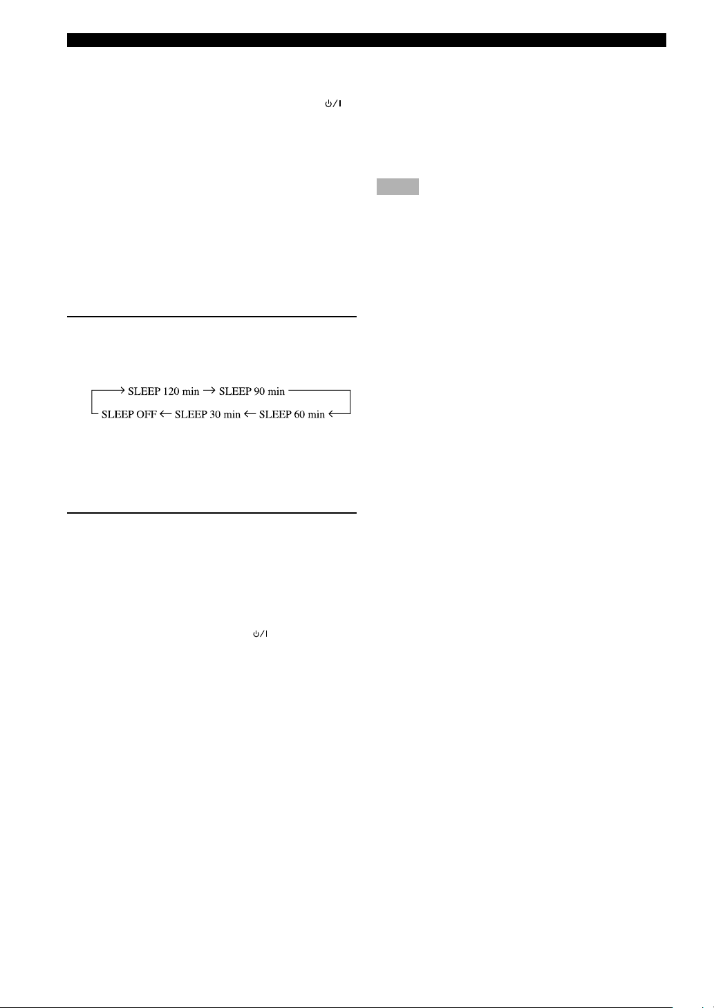
Press SLEEP repeatedly to set the amount of
time.
Each time you press SLEEP, the front panel display
changes as shown below.
The “SLEEP” indicator lights up on the front panel
display soon after the sleep timer has been set.
The display then returns to the previous indication.
Canceling the sleep timer
Press SLEEP repeatedly until “SLEEP OFF”
appears on the front panel display.
After a few seconds, “SLEEP OFF” disappears, the
“SLEEP” indicator goes off and the display returns
to the previous indication.
y
• The sleep timer setting can also be canceled by setting this unit
in the standby mode by using POWER ( ) on the remote
control (or STANDBY/ON on the front panel) or by
disconnecting the AC power cord from the AC outlet.
■ Input modes and indications
This unit comes with a variety of input jacks. You can
select the type of input signals you desire.
Press INPUT MODE (the input selector button that you
have pressed to select the input source on the remote
control) repeatedly until the desired input mode is shown
on the front panel display.
• AUTO: In this mode, the input signal is selected
automatically as follows:
1)Digital signal
2)Analog signal
• DTS: In this mode, only the digital input signal
encoded with DTS is selected.
• ANALOG: In this mode, only the analog input signal is
selected.
y
• When AUTO is selected, this unit automatically determines the
type of signal. If this unit detects a Dolby Digital or DTS
signal, the decoder automatically switches to the appropriate
setting.
• Each time you turn on the power of this unit, the input mode is
set according to “8 INPUT MODE” setting on the SET MENU
(see page 65 for details).
Notes
• When playing a disc encoded with Dolby Digital or DTS on
some LD players, the sound output delays for a moment when
playback resumes after a search because the digital signal is
selected again.
• When playing a LD source that has not been digitally recorded,
the sound may not be output for some LD players. In this case,
set the input mode to ANALOG.
Notes on playing DTS-CD/LDs
• If the digital output data of the player has been
processed in any way, you may not be able to perform
DTS decoding even if you make a digital connection
between this unit and the player.
• If you play a source encoded with a DTS signal and set
the input mode to ANALOG, this unit may reproduce
the noise of an unprocessed DTS signal. In this case,
connect the source to a digital input jack and set the
input mode to AUTO or DTS.
• If you switch the input mode to ANALOG while
playing a source encoded with a DTS signal, this unit
reproduces no sound.
• If you play a source encoded with a DTS signal with
the input mode set to AUTO;
– This unit automatically switches to the DTS-
decoding mode (The “t” indicator lights up) after
having detected the DTS signal. When playback of
the DTS source is completed, the “t” indicator
may flash. While this indicator is flashing, only DTS
source can be played. If you want to play a normal
PCM source soon, set the input mode back to AUTO.
– When the input mode is set to AUTO and a search or
skip operation is performed during playback of a
DTS source, the “t” indicator may flash. If this
status continues for longer than 30 seconds, this unit
will automatically switch from “DTS-decoding”
mode to PCM digital signal input mode. The “t”
indicator will turn off.
22
BASIC PLAYBACK
VIDEO 1
SHIFT
CODE SET
1
HALL2JAZZ
SETUP
3
ROCK
ANGLE
4
ENTERTAINMENT
MARKER
5
SPORTS6MONO MOVIE
PLAY MODE
7
MOVIE 1
REPEAT
8
MOVIE 2
A–B
DVDCDAMP
9
/DTS
TOP MENU
LEVEL
MENU
SET MENU
TEST
ON SCREEN
B. BOOST
RETURN
0
SELECT
>
–
10
MATRIX 6.1
GROUP
CANCEL
STEREO
PAGE
MUTE
VOL
ABCDE
ENTER
PRESET
CH CH
PRESET
Selecting a sound field program
This unit’s built-in DSP (Digital Sound field Processor) can simulate various acoustic environments, including a concert
hall and movie theater, with its 9 sound field programs. For the best results, choose a program appropriate for the
selected audio source.
1 Press AMP.
2 Press one of the DSP program buttons on
the remote control to select the desired
program.
3 After selecting the desired program, press
/DTS
SELECT
AMP
DSP program
buttons
STEREO
MATRIX6.1
the same button repeatedly to select the
d
desired sub-program if available.
y
• You can also select DSP program by pressing DSP H/G on the
front panel.
(U.S.A. model)
Indication on the front panel display (example):
Program name
DVD/CD
SP
MOVIE THTR
1
• Select the DSP program that you feel sounds best regardless of
the name and description given for it below.
70mm Spectacle
Sub-program name
USING BASIC FUNCTIONS
■ Feature of DSP programs
No.
1
2
3
4
Hi-Fi DSP (for music sources)
Program
CONCERT HALL
JAZZ CLUB
ROCK CONCERT
ENTERTAINMENT/
Disco
ENTERTAINMENT/
5ch Stereo
Features
A large round concert hall with a rich surround effect. Pronounced reflections from all directions
emphasize the extension of sounds. The sound field has a great deal of presence, and your
virtual seat is near the center, close to the stage.
This is the sound field at stage front in “The Bottom Line”, a famous New York jazz club, that
seats up to 300 people. Its wide left to right seating arrangement offers a real and vibrant sound.
The ideal program for lively, dynamic rock music. The data for this program was recorded at
LA’s “hottest” rock club. The listener’s virtual seat is at the center-left of the hall.
This program recreates the acoustic environment of a lively disco in the heart of a big city. The
sound is dense and highly concentrated. It is also characterized by a high-energy, “immediate”
sound.
Using this program increases the listening position range. This is a sound field suitable for
background music at parties, etc.
English
23
BASIC PLAYBACK
No.
4
5
Program
ENTERTAINMENT/
Game
ENTERTAINMENT/
Concert Video
TV SPORTS
CINEMA-DSP
6
(for video sources)
CINEMA-DSP
(for cinema sources)
DECODE
STRAIGHT
MONO MOVIE
7
MOVIE THEATER 1/
Spectacle
MOVIE THEATER 1/
Sci-Fi
8
MOVIE THEATER 2/
Adventure
MOVIE THEATER 2/
General
9
q/DTS/ENHANCED
9
q/DTS/NORMAL
Features
This program adds a deep and spatial feeling to video game sounds.
This program produces an enthusiastic atmosphere and lets you feel as if you are at an actual
jazz or rock concert.
With this program, you can enjoy watching various TV programs such as news, variety shows,
music programs or sports programs. In a stereo broadcast of a sports game, the commentator is
oriented at the center position, and the shouts and the atmosphere in the stadium spread on the
surround side, while their spread to the rear is properly restrained.
This program is provided for reproducing monaural video sources (such as old movies). The
program produces the optimum reverberation to create sound depth by using only the presence
sound field.
This program creates the extremely wide sound field of a 70-mm movie theater. It precisely
reproduces the source sound in detail, making both the video and the sound field incredibly real.
This is ideal for any kind of video source encoded with Dolby Surround, Dolby Digital or DTS
(especially large-scale movie productions).
This program clearly reproduces dialog and sound effects in the latest sound form of science
fiction films, thus creating a broad and expansive cinematic space amid the silence. You can
enjoy science fiction films in a virtual-space sound field that includes Dolby Surround, Dolby
Digital and DTS-encoded software employing the most advanced techniques.
This program is ideal for precisely reproducing the sound design of the newest 70-mm and
multichannel soundtrack films. The sound field is made to be similar to that of the newest movie
theaters, so the reverberations of the sound field itself are restrained as much as possible.
This program is for reproducing sounds from 70-mm and multichannel soundtrack films, and is
characterized by a soft and extensive sound field. The presence sound field is relatively narrow.
It spatially spreads all around and toward the screen, restraining the echo effect of conversations
without losing clarity.
This program ideally simulates the multi-surround speaker systems of the 35-mm film theaters.
Dolby Pro Logic and Dolby Pro Logic II decoding, Dolby Digital decoding or DTS decoding
and digital sound field processing create precise effects without altering the original sound
orientation.
The surround effects produced by this sound field wrap around the viewer naturally from the
back to the left and right, and toward the screen.
The built-in decoder precisely reproduces sounds and sound effects from sources. The highly
efficient decoding process improves crosstalk and channel separation and makes sound
positioning smoother and more precise.
In this program, no DSP effect is applied.
y
• When you set this unit in the standby mode, the current source and DSP program are memorized and are automatically selected when
you turn on the power again.
• When you select an input source, this unit automatically selects the last DSP program used with that source.
• The “ ” indicator does not light up when selecting program No. 9 except in Enhanced mode.
Notes
• There are 9 programs with sub-programs available with this unit. However, the selection depends on the input signal format and not
all sub-programs can be used with all input signal formats.
• The acoustics of your listening room affect the DSP program. Minimize the sound reflections in your room to maximize the effect
created by the program.
• When a monaural source is being played with PRO LOGIC/Normal or PRO LOGIC/Enhanced, or PRO LOGIC II Movie, no sound
will be heard from the front speakers and the rear speakers. Sound can only be heard from the center speaker. (If “1A CENTER” on
the SET MENU is set to NON, the center channel sound is output from the front speakers.)
24
BASIC PLAYBACK
■ Table of Program Names for Each Input Format
This unit automatically chooses the appropriate decoder and DSP sound field pattern according to the input signal
format.
No.
7
8
9
Input
Program
MOVIE
THEATER 1
MOVIE
THEATER 2
DOLBY
DIGITAL
DTS DIGITAL
SUR
PRO LOGIC
PRO LOGIC II
2 channel
ANALOG, PCM,
DOLBY DIGITAL, DTS
70 mm Spectacle
70 mm Sci-Fi
70 mm Adventure
70 mm General
—
—
—
—
Normal
Enhanced
Movie
Music
5.1 channel
DOLBY DIGITAL
DGTL Spectacle
DGTL Sci-Fi
DGTL Adventure
DGTL General
Normal
Enhanced
—
—
—
—
—
—
DTS
DTS Spectacle
DTS Sci-Fi
DTS Adventure
DTS General
—
—
Normal
Enhanced
—
—
—
—
6.1 channel *
DOLBY DIGITAL
+ Matrix 6.1
Spectacle 6.1
Sci-Fi 6.1
Adventure 6.1
General 6.1
Matrix 6.1
Enhanced 6.1
—
—
—
—
—
—
DTS
+ Matrix 6.1
Spectacle 6.1
Sci-Fi 6.1
Adventure 6.1
General 6.1
—
—
Matrix 6.1
Enhanced 6.1
—
—
—
—
* means the Matrix 6.1 decoder is ON.
y
• If Dolby Digital Surround EX software or DTS ES software is played when AUTO is selected by pressing the MATRIX 6.1 button on
the remote control, the Dolby Digital + Matrix 6.1 or DTS + Matrix 6.1 decoder usually turns on and the corresponding DSP
program is selected.
• MATRIX 6.1 on the remote control can be used to play Dolby Digital or DTS 5.1 channel sources with the virtual rear center
speaker. In this case the program name changes to the corresponding name for 6.1 channel.
• When playing a 6.1 channel source with MATRIX 6.1 on the remote control turned off, the program name changes to the
corresponding name for 5.1 channel.
USING BASIC FUNCTIONS
25
English

BASIC PLAYBACK
■ Selecting PRO LOGIC II
You can enjoy the 2-channel sources decoded into five
discrete channels by selecting PRO LOGIC II in program
No. 9.
(While playing a 2-channel source)
1 Press AMP.
2 Press q/DTS.
The previously selected sub program appears on the
front panel display.
3 Press SELECT repeatedly to select the
decoder, PRO LOGIC II.
4 After selecting on the decoder (PRO LOGIC
II), select the mode appropriate for the
source by pressing q/DTS.
The selection switches as follows;
PRO LOGIC II Movie ↔ PRO LOGIC II Music
y
• You can select PRO LOGIC, PRO LOGIC II Movie, and PRO
LOGIC II Music by pressing DSP H/G on the front panel
repeatedly.
Note
• Playback using DOLBY PRO LOGIC II decoders is possible
only for 2-channel signals.
■ Playing Dolby Digital Surround
EX or DTS ES software
Press MATRIX 6.1 to turn on the Dolby Digital + Matrix
6.1 or DTS + Matrix 6.1 decoder.
The rear center channel is created from rear left and right
channels, and output from virtual rear center speaker.
The display changes AUTO ^ Matrix6.1 ^ OFF each
time the MATRIX 6.1 button is pressed.
Notes
• Some Dolby Digital Surround EX or DTS ES software may not
contain the signal that is necessary for this unit to switch to the
Matrix 6.1 decoding mode. To turn on the Matrix 6.1 decoder
when playing such a source, select “Matrix6.1”.
• Playing a 6.1-channel source is not possible even if
MATRIX6.1 is pressed in the following cases:
– when “1C REAR LR” in the SET MENU is set to NON;
– when the sound effect is turned off;
– when headphones are connected;
– when a Dolby Digital KARAOKE source is being played;
– when 5ch Stereo is selected.
• The setting becomes AUTO once this unit turns into standby
mode.
■ Virtual CINEMA DSP
With Virtual CINEMA DSP, you can enjoy all DSP
programs without rear speakers. It creates virtual speakers
to reproduce a natural sound field.
You can listen to virtual CINEMA DSP by setting “1C
REAR LR” in the SET MENU to NON. Sound field
processing changes to VIRTUAL CINEMA DSP
automatically.
y
• When virtual CINEMA DSP is functioning, the “VIRTUAL”
indicator lights up on the front panel display.
Note
• This unit is not set in the virtual CINEMA DSP mode even if
“1C REAR LR” is set to NON in the following cases:
– when the 5ch Stereo, DOLBY DIGITAL Normal, Pro Logic
Normal, Pro Logic II, or DTS Normal program is selected;
– when the sound effect is turned off;
– when 96-kHz sampling digital signals are input to this unit;
– when using the test tone; or
– when connecting the headphones.
• AUTO: This mode automatically switches Dolby
Digital + Matrix 6.1 and DTS + Matrix 6.1
depending on the signal. Virtual rear center
speaker does not work for 5.1 channel
sources.
• Matrix6.1: This setting produces 6-channel playback
of the input source using the Matrix 6.1
decoder. The virtual rear center speaker can
be used when playing a 5.1-channel source.
• OFF: Virtual rear center speaker does not work in
this setting.
y
• When the Matrix 6.1 decoder is functioning, the “MATRIX”
indicator lights up on the front panel display.
26

BASIC PLAYBACK
■ SILENT CINEMA DSP
You can enjoy a powerful sound field similar to what you
could expert from actual speakers with SILENT
CINEMA DSP. You can listen to SILENT CINEMA DSP
by connecting your headphones to the
SILENT jack
while the digital sound field processor is on. Enjoy all the
DSP program using the headphones. The “SILENT”
indicator lights up on the front panel display. (When
sound effects are off, you listen to the source with normal
stereo reproduction.)
y
• When SILENT CINEMA DSP is functioning, the “SILENT”
indicator lights up on the front panel display.
Notes
• This feature is not available when 96-kHz sampling digital
signals are input to this unit.
• The sound of LFE channel will be mixed and output from the
headphone.
■ Normal Stereo Reproduction
Press STEREO to turn off the sound effect for normal
stereo reproduction.
Press STEREO again to turn the sound effect back on.
Notes
• If you turn off the sound effects, no sound is output from the
center or rear speakers.
• The volume may be greatly reduced when you turn off the
sound effects or if you set “4 D. RANGE” on the SET MENU
to MIN. In this case turn on the sound effect.
• The sound of LFE channel will be directed to the front left and
right or the subwoofer (or both) channels depending on the
setting of “1D BASS” on the SET MENU.
• If you turn off the sound effects while a Dolby Digital or DTS
signal is being output, the dynamic range of the signal is
automatically compressed and the sounds of the center and rear
speaker channels are mixed and output from the front speakers.
■ Displaying the information about
input signal
During stereo reproduction, you can display information
such as the type, format and sampling frequency of the
signal input from the components connected to this unit.
(While playing a stereo source)
1 Press AMP.
2 Press d to display the information about the
input signal.
y
• Format:
The type of an input signal. When digital input is not known,
the mode is set to the analog mode.
Input signal
Analog signal
PCM signal
Dolby Digital signal
DTS signal
Other digital signals
• fs:
The sampling frequency of an input signal when a digital signal
is input. If the frequency is not known, “unknown” appears on
the front panel display.
• Audio Channels:
The number of audio channels included in an input signal when
a Dolby Digital or DTS signal is input.
• Rate (bit rate):
The amount of data contained in an input signal per second
when a Dolby Digital or DTS signal is input. If the bit rate is
not known, “unknown” appears on the front panel display.
• Flg (flag):
An identification signal contained in an input signal when a
Dolby Digital or DTS signal is input. If the flag is not detected,
“None” appears on the front panel display.
Display
Analog
PCM
Dolby Digital
DTS
Unknwn Digital
(Unknown Digital)
■ Notes on 96-kHz sampling digital
signals
The digital input jacks of this unit can handle 96-kHz
sampling digital signals. Note the following when 96-kHz
sampling digital signal is input to this unit:
– DSP programs cannot be selected.
– Sound will be output as 2-channel stereo from only the
front left and right speakers. (There may be sound
output from the subwoofer depending on the
SPEAKER MODE settings on the SET MENU.)
Therefore, the level of the effect speakers cannot be
adjusted while listening to such a source.
USING BASIC FUNCTIONS
27
English

RECORDING
Recording adjustments and other operations are
performed from the recording components. Refer to the
operation instructions for these components.
1 Turn on the power of this unit and all
connected component.
2 Select the source component you want to
record from.
The procedure for selecting an input source is the
same as the one described in “BASIC PLAYBACK”
on page 21.
3 Start playback (or select a broadcast station)
on the source component.
4 Start recording on the recording component.
Notes
• Do a test recording before you start an actual recording.
• When this unit is set in the standby mode, you cannot record
between the components connected to this unit.
• The setting of BASS BOOST, VOLUME, “5 L/R BALANCE”
on the SET MENU and DSP programs does not effect the
recorded material.
• A given input source is not output to the same OUT (Rec)
channel. (For example, the signal input from VCR IN is not
output to VCR OUT.)
• Check the copyright laws in your country to record from
records, CDs, radio, etc. Recording of copyrighted material
may infringe copyright laws.
• It is not possible to record the sound effect created by this
unit’s DSP processing.
• While recording video images played during the DVD mode,
do not display ON-SCREEN menu. If displayed, the menu will
be also recorded.
• During digital recording, Karaoke vocal and Cinema dialog
functions do not work. (See pages 35 and 36.)
■ Special considerations when
recording DTS software
Attempting to digitally record the DTS bitstream will
result in noise being recorded.
■ Timer playback/recording
This unit can perform playback or recording with an
external timer (not supplied). Refer to the operating
instructions for the component and the timer to be used.
Notes
• Stored data, such as input source, will be reflected when
playback or recording with the timer.
• If you do not want any sound output when recording with a
timer, turn the volume down.
If you playback a video source that uses scrambled or
encoded signals to prevent it from being dubbed, the
picture itself may be disturbed due to those signals.
28
 Loading...