

Page 1

DVD HOME THEATER SYSTEM
SYSTEME HOME CINEMA AVEC LECTUER DVD
DVX-700
(DVR-700 + NS-PSW700 + NS-P700)
G
OWNER’S MANUAL
MODE D’EMPLOI
BEDIENUNGSANLEITUNG
BRUKSANVISNING
MANUALE DI ISTRUZIONI
MANUAL DE INSTRUCCIONES
GEBRUIKSAANWIJZING
Page 2
LASER INFORMATION
INFORMATION LASER
LASERINFORMATIONEN
LASERINFORMATION
INFORMAZIONI SUL LASER
INFORMACIÓN DE LÁSER
LASERINFORMATIE
ИНФОРМАЦИЯ О ЛАЗЕРЕ
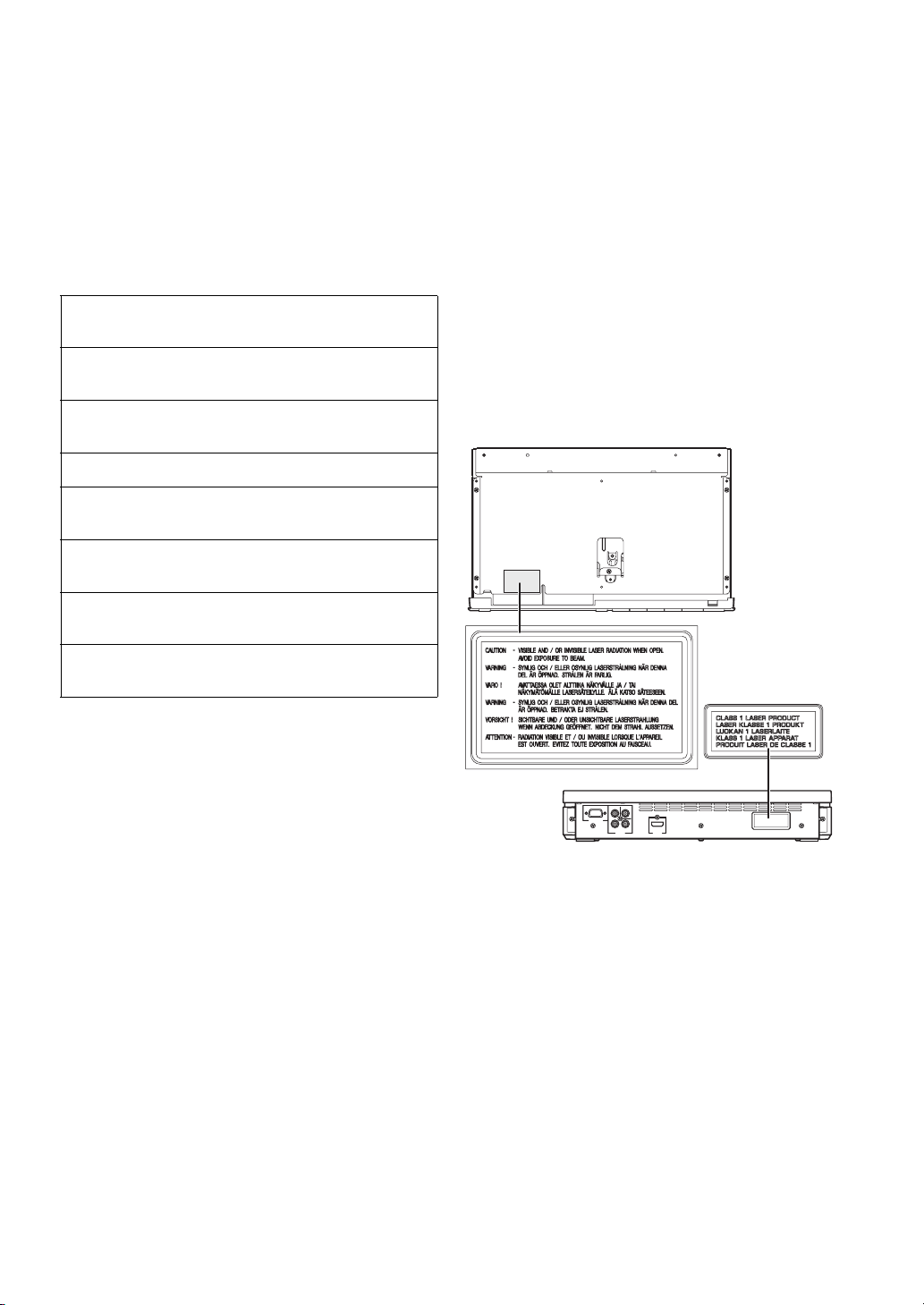
● The name plate is located on the rear panel of the DVD
controller.
● La plaque signalétique se trouve sur le panneau arrière du
lecteur de DVD.
● Das Typenschild befindet sich an der Rückseite des DVDControllers.
● Namnskylten sitter på DVD-enhetens baksida.
● La targhetta dati costruttore è posizionata sul pannello
posteriore del controller DVD.
● La placa de datos está situada en el panel trasero del
controlador de DVD.
● Het naamplaatje bevindt zich op het achterpaneel van de
DVD-receiver.
● Фирменная табличка расположена на задней
панели DVD-контроллера.
Without top cover
Sans couvercle supérieur
Ohne Abdeckung oben
Utan övre skydd
Senza coperchio superiore
Sin cubierta superior
Zonder bovenklep
Без верхней крышки
Page 3
Caution: read this before operating your unit.
1 To assure the finest performance, please read this manual
carefully. Keep it in a safe place for future reference.
2 Install this sound system in a well ventilated, cool, dry, clean
place — way from direct sunlight, heat sources, vibration,
dust, moisture, and/or cold. Allow ventilation space of at least
5 cm on the top, left, right, and the back of this unit.
3 Locate this unit away from other electrical appliances, motors,
or transformers to avoid humming sounds.
4 Do not expose this unit to sudden temperature changes from
cold to hot, nor locate this unit in an environment with high
humidity (i.e., a room with a humidifier) to prevent
condensation inside this unit, which may cause an electrical
shock, fire, damage to this unit, and/or personal injury.
5 Avoid installing this unit in a location where foreign objects
may fall onto this unit or where this unit may be exposed to
liquid dripping or splashing. On the top of this unit, do not
place:
– Other components, as they may cause damage and/or
discoloration on the surface of this unit.
– Burning objects (i.e., candles), as they may cause fire,
damage to this unit, and/or personal injury.
– Containers with liquid in them, as they may fall, spilling
the liquid and causing an electrical shock to the user and/
or damage to this unit.
6 Do not cover this unit with a newspaper, tablecloth, curtain,
etc. in order not to obstruct heat radiation. If the temperature
inside this unit rises, it may cause fire, damage to this unit,
and/or personal injury.
7 Do not plug in this unit to a wall outlet until all connections
are complete.
8 Do not operate this unit upside-down. It may overheat,
possibly causing damage.
9 Do not use excessive force on switches, knobs and/or cords.
10 When disconnecting the power cable from the wall outlet,
grasp the plug; do not pull the cable.
11 Do not clean this unit with chemical solvents; this might
damage the finish. Use a clean, dry cloth.
12 Use only the voltage specified on this unit. Using this unit
with a higher voltage than specified is dangerous and may
cause fire, damage to this unit, and/or personal injury.
Yamaha will not be held responsible for any damage resulting
from use of this unit with a voltage other than as specified.
13 To prevent damage by lightning, keep the power cable out and
outdoor antennas disconnected from a wall outlet or the unit
during a lightning storm.
14 Do not attempt to modify or fix this unit. Contact qualified
Yamaha service personnel when any service is needed. The
cabinet should never be opened for any reason.
15
When not planning to use this unit for long periods of time (i.e.,
vacation), disconnect the AC power plug from the wall outlet.
16 Be sure to read the “TROUBLESHOOTING” section on
common operating errors before concluding that this unit is
faulty.
17 Before moving this unit, press STANDBY/ON to set the unit
in standby mode, then disconnect the AC power plug from the
wall outlet.
18 Condensation will form when the surrounding temperature
changes suddenly. Disconnect the power cable from the
outlet, then leave the unit alone.
19 When using the unit for a long time, the unit may become
warm. Turn the power off, then leave the unit alone for
cooling.
20 Install this unit near the AC outlet and where the AC power
plug can be reached easily.
21 The batteries shall not be exposed to excessive heat such as
sunshine, fire or like.
22 Excessive sound pressure from earphones and headphones
can cause hearing loss.
23 When replacing the batteries, be sure to use batteries of the
same type. Danger of explosion may happen if batteries are
incorrectly replaced.
This unit is not disconnected from the AC power
source as long as it is connected to the wall outlet,
even if this unit itself is turned off. This state is called
the standby mode. In this state, this unit is designed to
consume a very small quantity of power.
Laser component in this product is capable of emitting
radiation exceeding the limit for Class 1.
WARNING
TO REDUCE THE RISK OF FIRE OR ELECTRIC
SHOCK, DO NOT EXPOSE THIS UNIT TO RAIN
OR MOISTURE.
CAUTION
Danger of explosion if battery is incorrectly replaced.
Replace only with the same or equivalent type.
This product complies with the radio interference
requirements of the European Community.
This product complies with the
requirements of the following directives
and guidelines: 2006/95/EC + 2004/
108/EC
Caution-i En
English
Page 4
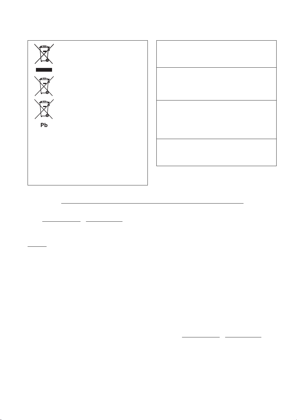
Information for Users on Collection and
Disposal of Old Equipment and used
Batteries
These symbols on the products, packaging, and/or
accompanying documents mean that used electrical and
electronic products and batteries should not be mixed
with general household waste. For proper treatment,
recovery and recycling of old products and used
batteries, please take them to applicable collection
points, in accordance with your national legislation and
the Directives 2002/96/EC and 2006/66/EC.
By disposing of these products and batteries correctly,
you will help to save valuable resources and prevent any
potential negative effects on human health and the
environment which could otherwise arise from
inappropriate waste handling.
For more information about collection and recycling of
old products and batteries, please contact your local
municipality, your waste disposal service or the point of
sale where you purchased the items.
[Information on Disposal in other Countries outside the European
Union]
These symbols are only valid in the European Union. If you wish to discard
these items, please contact your local authorities or dealer and ask for the
correct method of disposal.
Note for the battery symbol (bottom two symbol examples):
This symbol might be used in combination with a chemical symbol. In this
case it complies with the requirement set by the Directive for the chemical
involved.
Limited Guarantee for European Economic Area (EEA) and Switzerland
LASER SAFETY
This unit employs a laser. Due to possible eye injury, only a
qualified service person should remove the cover or attempt
to service this device.
DANGER
This unit emits visible laser radiation when open.
Avoid direct eye exposure to beam. When this unit is plugged
into a wall outlet, do not place your eyes close to the opening
of the disc loader and other openings or look inside.
LASER
Type Semiconductor laser ALGaInP
Wave length 655nm (DVD)
790nm (VCD/CD)
Output Power 5/7mW (DVD/VCD,CD)
Beam divergence 20degrees
CAUTION
Use of controls or adjustments or performance of procedures
other than those specified herein may result in hazardous
radiation exposure.
Thank you for having chosen a Yamaha product. In the unlikely event that your Yamaha product needs guarantee service, please contact the dealer from
whom it was purchased. If you experience any difficulty, please contact Yamaha representative office in your country. You can find full details on our
website (www.yamaha-hifi.com/
The product is guaranteed to be free from defects in workmanship or materials for a period of two years from the date of the original purchase. Yamaha
undertakes, subject to the conditions listed below, to have the faulty product or any part(s) repaired, or replaced at Yamaha’s discretion, without any charge
for parts or labour. Yamaha reserves the right to replace a product with that of a similar kind and/or value and condition, where a model has been
discontinued or is considered uneconomic to repair.
Conditions
1. The original invoice or sales receipt (showing date of purchase, product code and dealer’s name) MUST accompany the defective product, along with a
statement detailing the fault. In the absence of this clear proof of purchase, Yamaha reserves the right to refuse to provide free of charge service and the
product may be returned at the customer’s expense.
2. The product MUST have been purchased from an AUTHORISED Yamaha dealer within the European Economic Area (EEA) or Switzerland.
3. The product must not have been the subject of any modifications or alterations, unless authorised in writing by Yamaha.
4. The following are excluded from this guarantee:
a. Periodic maintenance and repair or replacement of parts due to normal wear and tear.
b. Damage resulting from:
(1) Repairs performed by the customer himself or by an unauthorised third party.
(2) Inadequate packaging or mishandling, when the product is in transit from the customer. Please note that it is the customer’s responsibility to
ensure the product is adequately packaged when returning the product for repair.
(3) Misuse, including but not limited to (a) failure to use the product for its normal purpose or in accordance with Yamaha’s instructions on the proper
use, maintenance and storage, and (b) installation or use of the product in a manner inconsistent with the technical or safety standards in force in
the country where it is used.
(4) Accidents, lightning, water, fire, improper ventilation, battery leakage or any cause beyond Yamaha’s control.
(5) Defects of the system into which this product is incorporated and/or incompatibility with third party products.
(6) Use of a product imported into the EEA and/or Switzerland, not by Yamaha, where that product does not conform to the technical or safety
standards of the country of use and/or to the standard specification of a product sold by Yamaha in the EEA and/or Switzerland.
(7) Non AV (Audio Visual) related products.
(Products subject to “Yamaha AV Guarantee Statement” are defined in our website at www.yamaha-hifi.com/
resident.)
5. Where the guarantee differs between the country of purchase and the country of use of the product, the guarantee of the country of use shall apply.
6. Yamaha may not be held responsible for any losses or damages, whether direct, consequential or otherwise, save for the repair or replacement of the
product.
7. Please backup any custom settings or data, as Yamaha may not be held responsible for any alteration or loss to such settings or data.
8. This guarantee does not affect the consumer’s statutory rights under applicable national laws in force or the consumer’s rights against the dealer arising
from their sales/purchase contract.
or www.yamaha-uk.com/ for U.K. resident).
or www.yamaha-uk.com/ for U.K.
Caution-ii En
Page 5

CONTENTS
1
1. INTRODUCTION
INTRODUCTION ......................................... 2
Main unit ............................................................. 4
Supplied accessories............................................ 4
FUNCTIONAL OVERVIEW ......................... 5
Front panel (DVR-700) ....................................... 5
Rear panel (DVR-700) ........................................ 6
Front panel display (DVR-700) ........................... 7
Rear panel (NS-PSW700).................................... 8
Remote control .................................................... 9
2. CONNECTIONS
CONNECTIONS ........................................ 11
Roles and layout of the speakers ....................... 11
Placing the speakers using the stands ................ 12
Placing the speakers on a wall ........................... 12
SYSTEM CONNECTIONS......................... 14
Connecting the speakers .................................... 14
Connecting the DVD controller and the subwoofer/
system control................................................ 16
OTHER CONNECTIONS........................... 17
Connecting a TV................................................ 17
Connecting an HDMI component ..................... 18
Connecting the FM antenna............................... 18
Connecting external AV components................ 19
Connecting the power cable .............................. 20
3. PREPARATION
GETTING STARTED................................. 21
Inserting batteries into the remote control ......... 21
Using the remote control ................................... 21
Turn on the system ............................................ 22
Setting the video input/output ........................... 23
Setting language preferences............................. 25
4. BASIC OPERATIONS
DISC OPERATION.................................... 26
Playing discs ...................................................... 26
Basic playback controls ..................................... 27
Ejecting a disc.................................................... 28
Using the disc menu (DVD only) ...................... 28
Playback control (PBC) (Video CD only)......... 28
Changing soundtrack language.......................... 28
Changing subtitle language ............................... 29
Resuming playback from the last stopped point 29
Viewing from another angle .............................. 29
Displaying disc information .............................. 29
Zooming in ........................................................ 29
Advanced operation ........................................... 30
Disc navigator.................................................... 32
PLAYING OTHER DISCS ......................... 33
To play back audio files .................................... 33
To start a slide show of JPEG files.................... 34
Selecting a file to play back............................... 34
Using a USB device........................................... 35
5. DVD SETUP MENU
DVD SETUP MENU OPTIONS................. 36
Menu overview................................................... 36
VIDEO ADJUST MENU ............................ 37
INITIAL SETTINGS MENU....................... 38
Video Output ...................................................... 38
Language ............................................................ 40
Display ............................................................... 41
Options ............................................................... 41
6. OTHER FUNCTIONS
AIR SURROUND XTREME ...................... 43
What is AIR SURROUND XTREME? ............. 43
Listening to surround mode of AIR SURROUND
XTREME ....................................................... 43
Shifting the optimum listening area from side to
side ................................................................. 44
Selecting the optimum distance between the
speakers .......................................................... 44
Checking the virtual surround effect.................. 45
Using extended stereo mode .............................. 45
Setting compressed music enhancer................... 45
LISTENING TO FM BROADCASTS......... 46
Basic tuning operation........................................ 46
Using station preset feature ................................ 47
Recalling the preset stations............................... 49
Receiving Radio Data System stations
(Europe and Russia models only) .................. 49
USING OPTIONAL EQUIPMENT............. 52
Using iPod™ ...................................................... 52
Using Bluetooth™ components ......................... 53
7. USEFUL OPERATION
USEFUL OPERATION.............................. 55
Adjusting the audio delay................................... 55
Listening at low volume (night listening mode) 55
Adjusting the audio balance for the playback.... 56
Changing the brightness of the front panel
display ............................................................ 56
Setting the sleep timer ........................................ 57
System menu ...................................................... 57
Setting the preset code ....................................... 58
8. ADDITIONAL INFORMATION
TROUBLESHOOTING.............................. 59
GLOSSARY .............................................. 64
SPECIFICATIONS .................................... 66
INDEX ....................................................... 67
APPENDIX
LIST OF PRESET CODES................................... i
LIST OF COUNTRY CODES ........................... iii
LIST OF LANGUAGE CODES ......................... iv
2
3
4
5
6
7
8
English
1 En
Page 6
INTRODUCTION
INTRODUCTION
Thank you for purchasing this unit. This Owner’s Manual
explains the basic operation of this unit.
Notes about discs
– This DVD controller is designed for use with the
following discs.
DVD disc: DVD-Video, DVD-R/-RW/-R
DL, DVD+R/+RW/+R DL
Compact Disc: Audio CD, CD-R, CD-RW,
Video CD, Super Video CD
Notes
– DVD-R/-RW/-R DL and DVD+R/+RW/+R DL
discs recorded in DVD-Video compatible format.
– DVD-R/-RW/-R DL discs recorded in VR format
(compatible with CPRM).
– CD-R/RW, DVD-R/-RW/-R DL and DVD+R/
+RW/+R DL cannot be played unless finalized.
– Multi-session discs are not supported.
– Some discs recorded on PC cannot be played
depending on the settings of the application
software.
– Discs recorded on PC in packet write format are
not compatible with this DVD controller.
– This unit is not compatible with 8-cm discs.
This controller can play the following formatted files
recorded on CD-R/RW, DVD-R/-RW, DVD+R/+RW and
USB device.
Compressed audio file
– MPEG1 audio layer3 (MP3)
– Windows Media Audio (WMA)
– MPEG-4 AAC
Still image file
–JPEG
– FUJICOLOR CD
– KODAK Picture CD
Movie file
(except files saved on USB devices)
–WMV
®
–DivX
Ultra
– Official DivX
®
Ultra Certified product.
– Plays all versions of DivX
®
6) with enhanced playback of DivX®
DivX
media files and the DivX
®
video (including
®
Media Format.
Hint
Refer to “DISC OPERATION” on page 26 for details.
Cleaning discs
– When a disc becomes dirty, clean it with a cleaning
cloth. Wipe the disc from the center out. Do not
wipe in a circular motion.
– Do not use solvents such as benzine, thinner,
commercially available cleaners, or antistatic spray
intended for analog records.
Avoid high temperatures, moisture, water
and dust
– Do not expose the system, batteries or discs to
humidity, rain, sand or excessive heat (caused by
heating equipment or direct sunlight).
Avoid condensation problem
– The lens may cloud over when the controller is
suddenly moved from cold to warm surroundings,
making it impossible to play a disc. Leave the
controller in the warm environment until the
moisture evaporates.
Disc care
– Write only on the printed side of a CD-R/RW,
DVD-R/-RW/-R DL, DVD+R/+RW/+R DL and
only with a soft felt tipped pen.
– Handle the disc by its edge; do not touch the
surface.
Lens care
– Basically, lens cleaning is not necessary.
– Do not use lens cleaner because it may cause
malfunction.
Cabinet care
– Use a soft cloth slightly moistened with a mild
detergent solution. Do not use a solution containing
alcohol, spirits, ammonia, or abrasives.
Choosing a suitable location
– Place the controller on a flat, hard, and stable
surface.
2 En
Page 7
INTRODUCTION
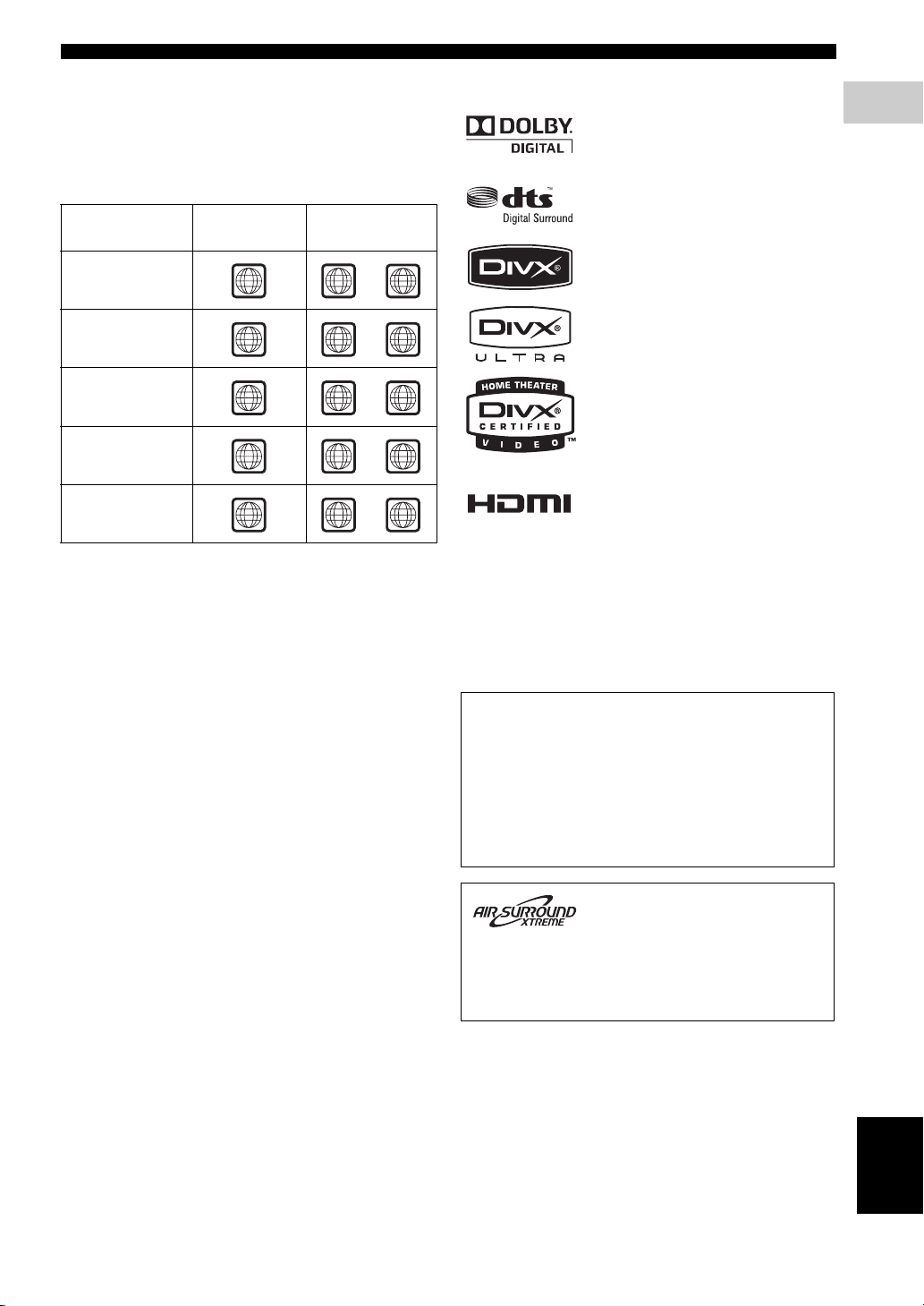
Region codes
The unit is designed to support the Region Management
System. Check the region code number on the disc
package. If the number does not match the unit’s region
number (Refer to the table below or the back of the unit),
the unit may be unable to play the disc.
Destination
U.S.A., and
Canada model
Europe
model
Asia and Taiwan
models
Australia
model
Russia
model
Region code
of DVR-700
1 1
2 2
3 3
4 4
5 5
Playable discs
ALL
ALL
ALL
ALL
ALL
Features
Manufactured under license from Dolby
Laboratories. “Dolby”, “Pro Logic”,
“MLP Lossless” and the double-D symbol
are trademarks of Dolby Laboratories.
“DTS” and “DTS Digital Surround” are
registered trademarks of DTS, Inc.
®
, DivX® Ultra Certified, and
DivX
associated logos are trademarks of
®
DivX
, Inc. and are used under license.
HDMI, the HDMI logo and High
Definition Multimedia Interface are
trademarks or registered trademarks of
HDMI Licensing LLC.
“Apple”, “iPod”, and “iTunes” are trademarks of Apple Inc.,
registered in the U.S. and other countries.
Bluetooth is a registered trademark of Bluetooth SIG and is used
by Yamaha in accordance with a license agreement.
Windows Media is either a registered trademark or trademark of
Microsoft Corporation in the United States and/or other countries.
1
INTRODUCTION
This product incorporates copyright protection
technology that is protected by U.S. patents and other
intellectual property rights. Use of this copyright
protection technology must be authorized by
Macrovision, and is intended for home and other
limited viewing uses only unless otherwise authorized
by Macrovision. Reverse engineering or disassembly
is prohibited.
This system employs new technologies and algorithms
that make it possible to achieve 7-channel surround
sound with only two speakers, and without using wall
reflections.
English
3 En
Page 8
INTRODUCTION
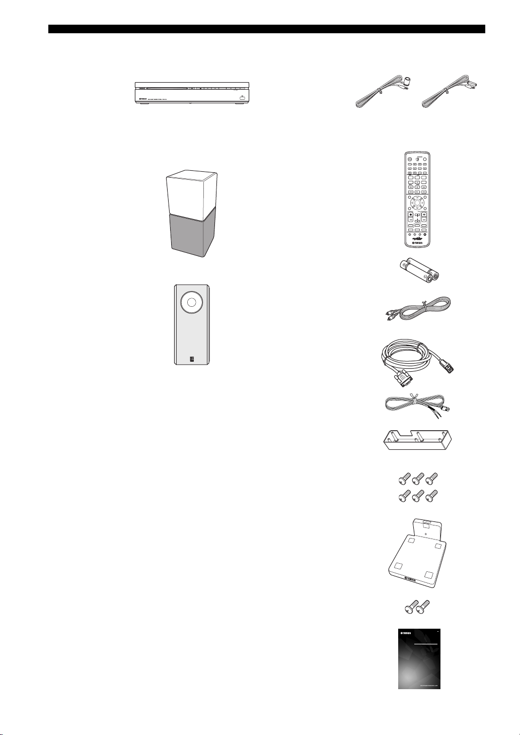
■ Main unit ■ Supplied accessories
Indoor FM antenna
DVD controller
(DVR-700)
(U.S.A., Canada,
Asia and Taiwan
models)
(Europe, Russia
and Australia
models)
Speaker package
Speaker (L/R)
(NS-P700)
Subwoofer/system control
(NS-PSW700)
Remote control
Battery x 2
(AA, R6, UM-3)
Video pin cable (1.5 m)
System control cable (4 m)
Speaker cable x 2 (4 m)
Cover
(For NS-PSW700)
WP87020DVX-700
/
ON
STANDBY
TV STB
FUNC.
10KEY
MUSIC
MOVIE
ENHANCER
STEREO
AUDIO DELAY
DISP. MODE
BLUETOOTH
ON OFF
AUDIO
SUBTITLE
PLAY MODE
PTY SEEK
START
MODE
AUTO
/
MANUAL
PRESET
/
TUNE
TOP MENU
PRESET
INFO.
A-E A-E
ENTER
SETUP RETURN
TV
/
STB
CH
TV VOL
TUNER MUTE
TV INPUT
DVD
/
USB INPUT 1-4
POSITION
AREA SOUND TEST
POWER
GAMESPORTS
SLEEP
NIGHT
ON SCREEN
ZOOM
ANGLE
CLEAR
FREQ / TEXT
MEMORY
MENU
CODE SET
VOLUME
DOCK
4 En
Screw x 6
(for cover 3 x 6 mm)
Stand x 2
(For NS-P700)
Screw x 2
(for stand 4 x 10 mm)
Owner’s Manual
DVD HOME THEATER SYSTEM
SYSTEME HOME CINEMA AVEC LECTUER DVD
DVX-700
(DVR-700 + NS-PA700)
OWNER’S MANUAL
BEDIENUNGSANLEITUNG
BRUKSANVISNING
MANUALE DI ISTRUZIONI
MANUAL DE INSTRUCCIONES
GEBRUIKSAANWIJZING
G
MODE D’EMPLOI
Page 9
FUNCTIONAL OVERVIEW
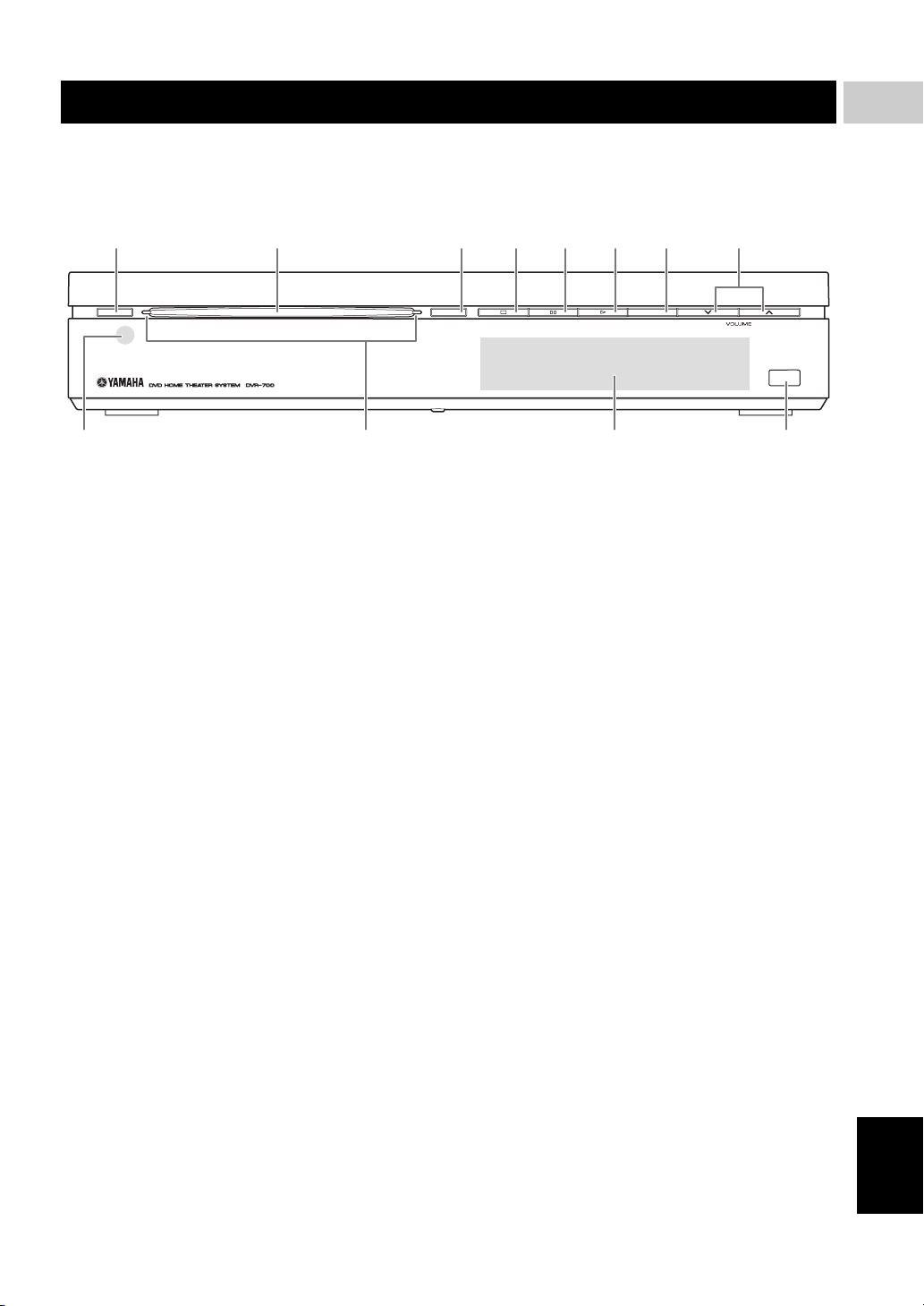
■ Front panel (DVR-700)
12 345678
1
INTRODUCTION
STANDBY / ON
1 STANDBY/ON
Turns on the system, or sets it to standby mode
(Page 22).
2 Disc loading slot
Insert a disc to be played.
3 EJECT
Ejects a disc in the DVD controller.
4 s
Stops playback.
5 e
Pauses playback.
6 h
Starts playback.
EJECT INPUT
USB
B09A
7 INPUT
Selects an input source by pressing repeatedly.
8 VOLUME u / d
Adjusts the volume level.
9 Remote control sensor
Point the remote control towards this sensor.
0 Power indicator
Lights up when system is on.
A Front panel display
Shows information about the operational status of the
unit.
B USB terminal
Connect to the USB connector of your USB device
(Page 35).
5 En
English
Page 10

FUNCTIONAL OVERVIEW
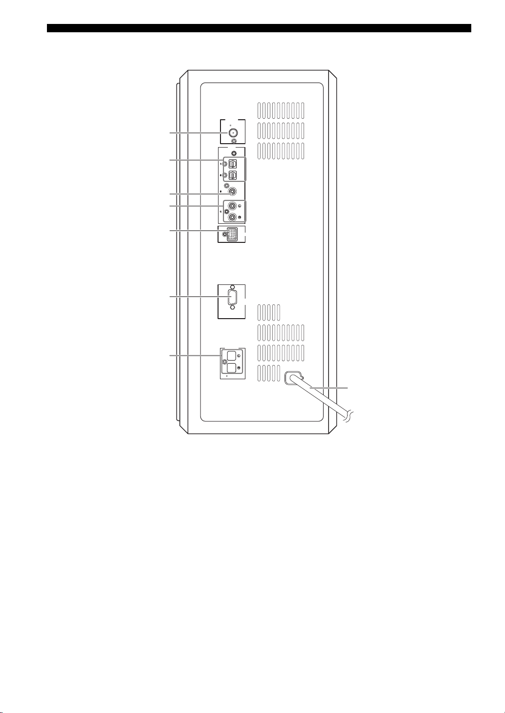
■ Rear panel (DVR-700)
1234
NS-PSW700
SYSTEM
CONNECTOR
P
Y
B
VIDEO
COMPONENT
VIDEO
OUTPUT
PR
HDMI
OUTPUT
1 SYSTEM CONNECTOR terminal
Connect to the subwoofer/system control (Page 16).
2 COMPONENT VIDEO OUTPUT jacks
Connect to the Y PB/CB PR/CR jacks on your TV
(Page 17).
3 VIDEO OUTPUT jack
Connect to the video (composite) jack on your TV
(Page 17).
4 HDMI OUTPUT terminal
Connect to the HDMI input terminal on your TV
(Page 18).
6 En
Page 11
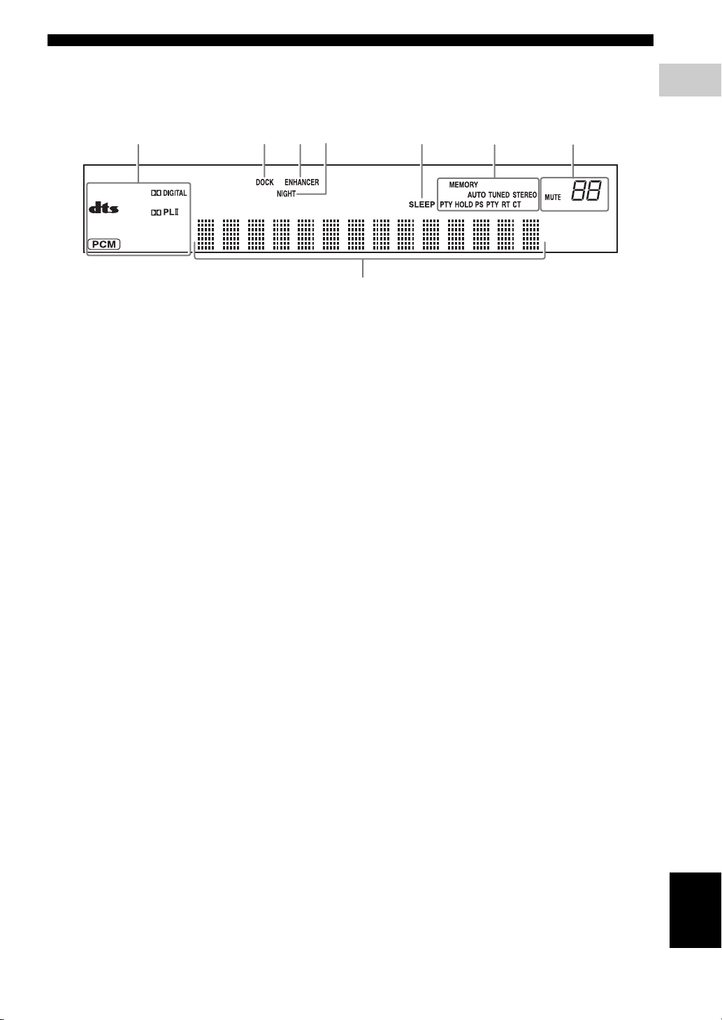
■ Front panel display (DVR-700)
FUNCTIONAL OVERVIEW
1
INTRODUCTION
12345
1 Decoder indicators
The respective indicator lights up when any of the
decoders of the system is functioning.
2 DOCK indicator
– Lights up when the system is receiving a signal
from an iPod stationed in the Yamaha iPod
universal dock (such as YDS-10 or YDS-11, sold
separately) connected to the DOCK terminal of the
subwoofer/system control (Page 20).
– Lights up while the Yamaha Bluetooth wireless
audio receiver (such as YBA-10, sold separately) is
connected to the Bluetooth component (Page 53).
– Flashes while the connected Yamaha Bluetooth
wireless audio receiver (such as YBA-10, sold
separately) and the Bluetooth component are
pairing or while the Yamaha Bluetooth wireless
audio receiver is searching for the Bluetooth
component (Page 53).
3 ENHANCER indicator
Lights up when compressed music enhancer mode is
selected (Page 45).
4 NIGHT indicator
Lights up when you select night listening mode
(Page 55).
5 SLEEP indicator
Lights up when sleep mode is on (Page 57).
68
7
6 Tuner indicators (AUTO/TUNED/STEREO/
MEMORY/PTY HOLD/PS/PTY/RT/CT)
AUTO indicator
Lights up when the system is in automatic tuning
mode (Page 46).
TUNED indicator
Lights up when the system is receiving a station
(Page 46).
STEREO indicator
Lights up when the system is receiving a strong signal
from an FM stereo broadcast in automatic tuning
mode (Page 46).
MEMORY indicator
Flashes to show a station can be stored (Page 47).
PTY HOLD indicator
Lights up while the system is in PTY SEEK mode.
PS/PTY/RT/CT indicator
Lights up according to the available Radio Data
System information (Page 49).
7 Multi information display
Shows the information, such as playing time and
selected input source. When you adjust or change a
setting, the value is displayed.
8 MUTE indicator/VOLUME indicator
– Flashes while the mute function is activated.
– Indicates the current volume level.
7 En
English
Page 12
FUNCTIONAL OVERVIEW
■ Rear panel (NS-PSW700)
1
2
3
4
ANTENNA
75
INPUT
FM
UNBAL
.
OPTICAL
OPTICAL
COAXIAL
ANALOG
5
6
7
1 ANTENNA terminal
Connect the FM antenna.
2 INPUT 1/2 OPTICAL jacks
Connect to the DIGITAL OUT jack (Optical Type) on
your digital audio component.
These input jacks support PCM, Dolby Digital, and
DTS bitstream.
3 INPUT 3 COAXIAL jack
Connect to the DIGITAL OUT jack (Coaxial Type) on
your digital audio component.
This input jack support PCM, Dolby Digital, and DTS
bitstream.
4 INPUT 4 ANALOG jacks
Connect to the ANALOG OUT jack if the component
does not have DIGITAL OUT jacks.
DVR-700
SPEAKERS
SPEAKER
:
6 MIN.
IMPEDANCE
DOCK
SYSTEM
CONNECTOR
MAINS
8
5 DOCK terminal
Connect the Yamaha iPod Universal Dock (such as
YDS-10 or YDS-11, sold separately) or Yamaha
Bluetooth wireless audio receiver (such as YBA-10,
sold separately) (Page 20).
6 SYSTEM CONNECTOR terminal
Connect to the DVD controller.
7 SPEAKER terminals
Connect to the speakers.
8 Power cable
Connect to a standard AC outlet.
8 En
Page 13

FUNCTIONAL OVERVIEW
■ Remote control
STANDBY
1
2
4
5
MOVIE
STEREO
DISP. MODE
ON OFF
AUDIO
6
8
9
PLAY MODE
MODE
A
B
PRESET/ TUNE
D
E
G
I
TOP MENU
INFO.
A-E A-E
SETUP RETURN
K
M
TV VOL
TV INPUT
P
DVD
POSITION
Q
R
1 STANDBY/ON ( )
Turns on the this system, or sets it to the standby
mode.
2 FUNC./10KEY
Switches the operation of the Function/Numeric
keypad keys. Also, the preset code to operate TV or
STB.
Hint
Using the remote control, you can operate two kinds
of peripheral devices such as TV and satellite tuner.
When operating them, you need to set the preset codes
depending on the components. Refer to “Setting the
preset code” on page 58.
WP87020DVX-700
/
ON
TV STB
FUNC.
MUSIC
ENHANCER
AUDIO DELAY
BLUETOOTH
SUBTITLE
PTY SEEK
START
AUTO/
MANUAL
PRESET
ENTER
TV
/
STB
CH
TUNER MUTE
/
USB INPUT 1-4
AREA SOUND TEST
10KEY
NIGHT
ZOOM
POWER
GAMESPORTS
SLEEP
ON SCREEN
ANGLE
CLEAR
FREQ / TEXT
MEMORY
MENU
CODE SET
VOLUME
DOCK
3
7
0
C
F
H
J
L
N
O
t
S
3 POWER
Turns on the TV.
Note
To operate your TV with the remote control, you need
to set the preset code. Refer to “Setting the preset
code” on page 58.
4 Function / Numeric keypad 0-9
Operates some functions, such as AIR SURROUND
XTREME, and enters track numbers or other
numbers.
The available operation will be changed depending on
the FUNC./10KEY position.
FUNC./10KEY: FUNC. side
MOVIE
MUSIC
SPORTS
Select surround mode.
GAME
STEREO – Turns extended stereo mode
on and off alternately
(Page 45).
– Turns surround mode off
(Page 43).
ENHANCER Turns compressed music
enhancer mode on and off
alternately (Page 45).
NIGHT Turns night listening mode on
and off alternately (Page 55).
SLEEP Sets the sleep timer (Page 57).
DISP. MODE Changes the brightness of the
front panel display (Page 56).
AUDIO DELAY Delays the output sound to
synchronize it with the video
image (Page 55).
ZOOM Enlarges the pictures while
playing DVD.
Hint
This button can be used
regardless of the FUNC./10KEY
position.
ON SCREEN Displays the disc information on
the TV display.
Hint
This button can be used
regardless of the FUNC./10KEY
position.
FUNC./10KEY: 10KEY side
Enters numeric characters using 0 to 9 buttons.
1
INTRODUCTION
English
9 En
Page 14

FUNCTIONAL OVERVIEW
5 AUDIO
Selects an audio language for the DVD that is playing
(if available).
6 SUBTITLE
Selects a subtitle language for the DVD that is playing
(if available).
7 ANGLE
Selects a camera angle for the DVD that is playing (if
available).
8 PLAY MODE
Displays the Play Mode menu.
9 s
Stops playback.
0 CLEAR
Erases the registered track/chapter order.
A w (PTY SEEK MODE)
Rewinds the disc.
FM: sets the system to the PTY SEEK mode.
B e (PTY SEEK START)
Pauses playback.
FM: starts searching for a Radio Data System station.
C f (FREQ/TEXT)
Fast-forwards the disc.
FM: switches the information display when receiving
Radio Data System.
D b (PRESET/TUNE)
Selects the previous track or chapter.
FM: switches how to select the radio station (preset or
radio frequency) (Page 49).
E h (AUTO/MANUAL)
Starts playback.
FM: selects auto/manual tuning (Page 46).
F a (MEMORY)
Selects the next track or chapter.
FM: registers the radio frequency.
G TOP MENU (INFO.)
Displays the top-level disc menu.
iPod: switches operation mode of the iPod.
H MENU
Displays the disc contents menu.
K SETUP
Displays the DVD setup menu.
L RETURN (CODE SET)
– Returns to the previous screen when DVD setup
menu is displayed.
– Use to set the preset code. Refer to “Setting the
preset code” on page 58.
M TV/STB control buttons
TV VOL +/–
Adjusts the TV volume level.
CH +/–
Select the TV channel.
TV INPUT
Selects the TV input.
Note
To operate your TV with the remote control, you need
to set the preset code. Refer to “Setting the preset
code” on page 58.
You can select TV or STB by switching FUNC./
10KEY.
N VOLUME +/–
Adjusts the volume level of DVX-700.
O MUTE
Mutes the volume of DVX-700. Press the button again
to mute OFF.
P Input selection buttons
DVD/USB
Switches the input source to DVD or USB. Each time
you press the button, the input source changes in
sequence.
TUNER
Switches the input source to FM.
INPUT 1-4
Switches the input source to the external input. Each
time you press the button, the input source changes in
sequence from input 1 to input 4.
DOCK
Switches the input source to DOCK.
Selects iPod or Bluetooth as the input source
depending on the option connected to the Dock
terminal.
Q POSITION
Shifts the optimum listening area according to your
listening position (Page 44).
I Cursors ( / / / )
Selects items or changes values in the menu screen.
– Tuning the FM station.
– Controlling an iPod.
– Changing the settings.
J ENTER
Confirms a selection.
10 En
R AREA
Sets the distance between speakers for the best
surround effect (Page 44).
S SOUND
Adjusts the volume balance for the virtual speaker and
subwoofer (Page 56).
T TEST
Outputs the test tone (Page 45).
Page 15
CONNECTIONS
CONNECTIONS
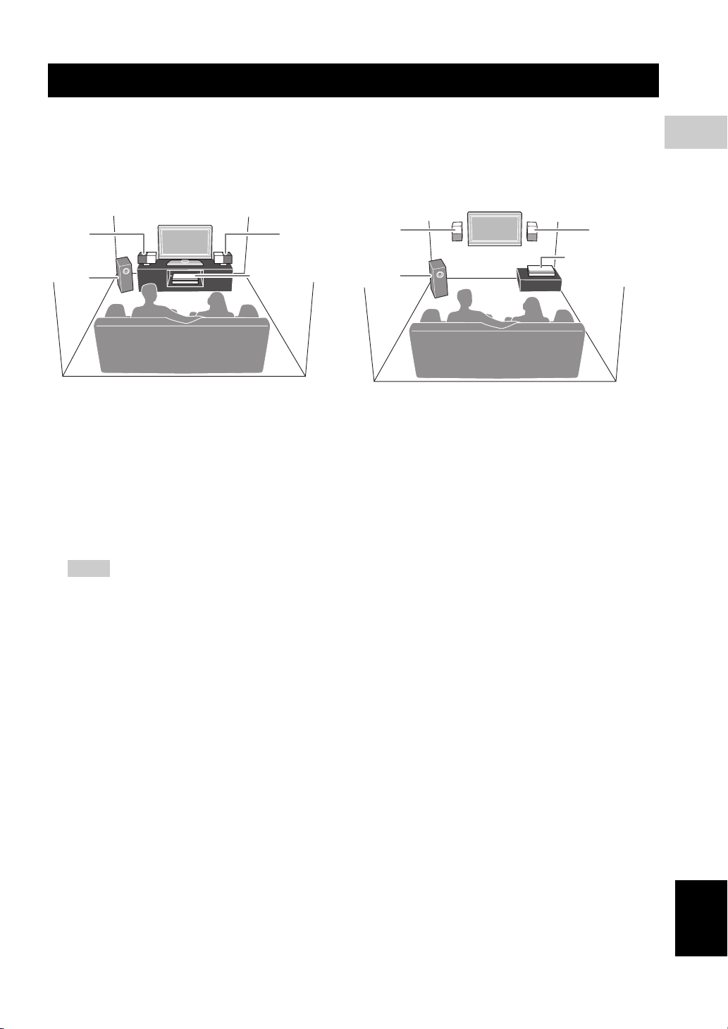
■ Roles and layout of the speakers
To enjoy quality sounds, you need to place the speakers in their appropriate positions and install them correctly.
The following shows the recommended layout of the speakers.
When placing the speakers on a rack When placing the speakers on a wall
11
2
1 Speaker (L, R)
Produces front channel (stereo) sounds. Also produces virtual center channel sounds (dialogue, etc.) and virtual
surround channel sounds effectively using the Yamaha front surround system.
Place the left and right speakers at equal distances away from the listening position so that you can produce high
quality surround sound. You can install the speakers on a rack using the stands or on a wall.
2 Subwoofer/system control
The subwoofer produces bass sounds and LFE sounds contained in Dolby Digital or DTS. Place the subwoofer in the
front of the listening position. Turn it slightly toward the center of the room to reduce wall reflections.
DVD controller
11
DVD controller
2
2
CONNECTIONS
Notes
– To avoid magnetic interference, do not position the speakers too close to your TV.
– Allow adequate ventilation around the DVD controller and subwoofer/system control.
– Bass sounds produced by the subwoofer may be heard differently depending on the listening position and
subwoofer location.
To enjoy desired sounds, try to change the location of the subwoofer according to the listening position.
– You can adjust the surround effect by arranging the position of the speakers (Page 46).
English
11 En
Page 16
CONNECTIONS
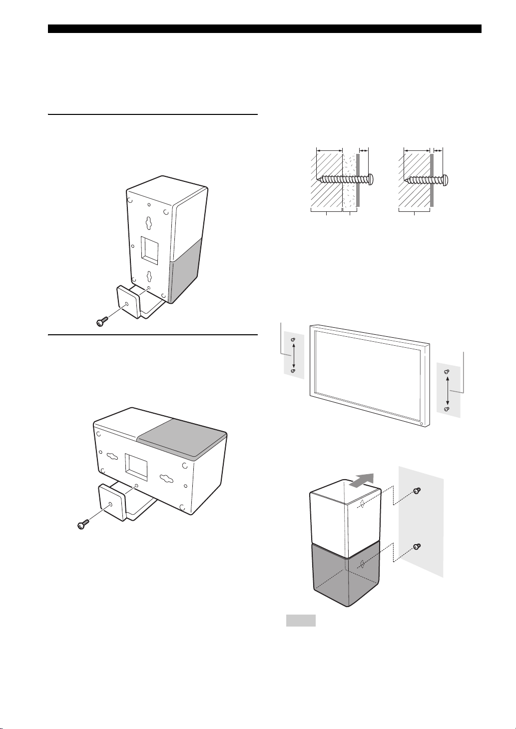
■ Placing the speakers using the stands
You can place the speakers in an upright position or a
horizontal position. Put the speakers on the stands and
secure them with the screws.
When placing the speaker in an
upright position
Place the speaker on the stand vertically, and then secure it
with the screw as shown in the illustration.
■ Placing the speakers on a wall
Put the speakers on a wall using commercially available
screws. Refer to the illustration below for the screw size.
Tapping screw (Available at the hardware store)
Dia.4 mm (1/8")
Installing on a plaster wall.
Min 20 mm
(3/4")
PlasterPillar
or lumber
1 When placing the speakers on a wall, remove the
stands.
2 Install screws on a wall as shown in the illustration.
The distance between the screws: 126 mm for both
sides
126 mm (5")
Installing on a firm wall.
5 mm
(1/4")
Min 20 mm
(3/4")
Pillar
or lumber
5 mm
(1/4")
When placing the speakers in a
horizontal position
Put the speaker on the stand so that the black side of the
speaker becomes outside, and then secure it with the screw
as shown in the illustration.
126 mm (5")
3 Insert the screws into the holes on the back of the
speaker.
Notes
– To attach the speaker to a wall with screws, the
wall must be firm. If not you may cause the speaker
to fall.
12 En
Page 17

– Use commercially available screws that can
support the weight of the installation.
– Make sure you use specified screws to attach the
speakers to a wall. Using clamps other than
specified screws, such as short screws, nails, or
two-sided tape, may cause the speaker to fall.
– After attaching the speakers, check that the
speakers are installed securely. Yamaha will bear
no responsibility for any accidents caused by
improper installations.
CONNECTIONS
2
CONNECTIONS
13 En
English
Page 18
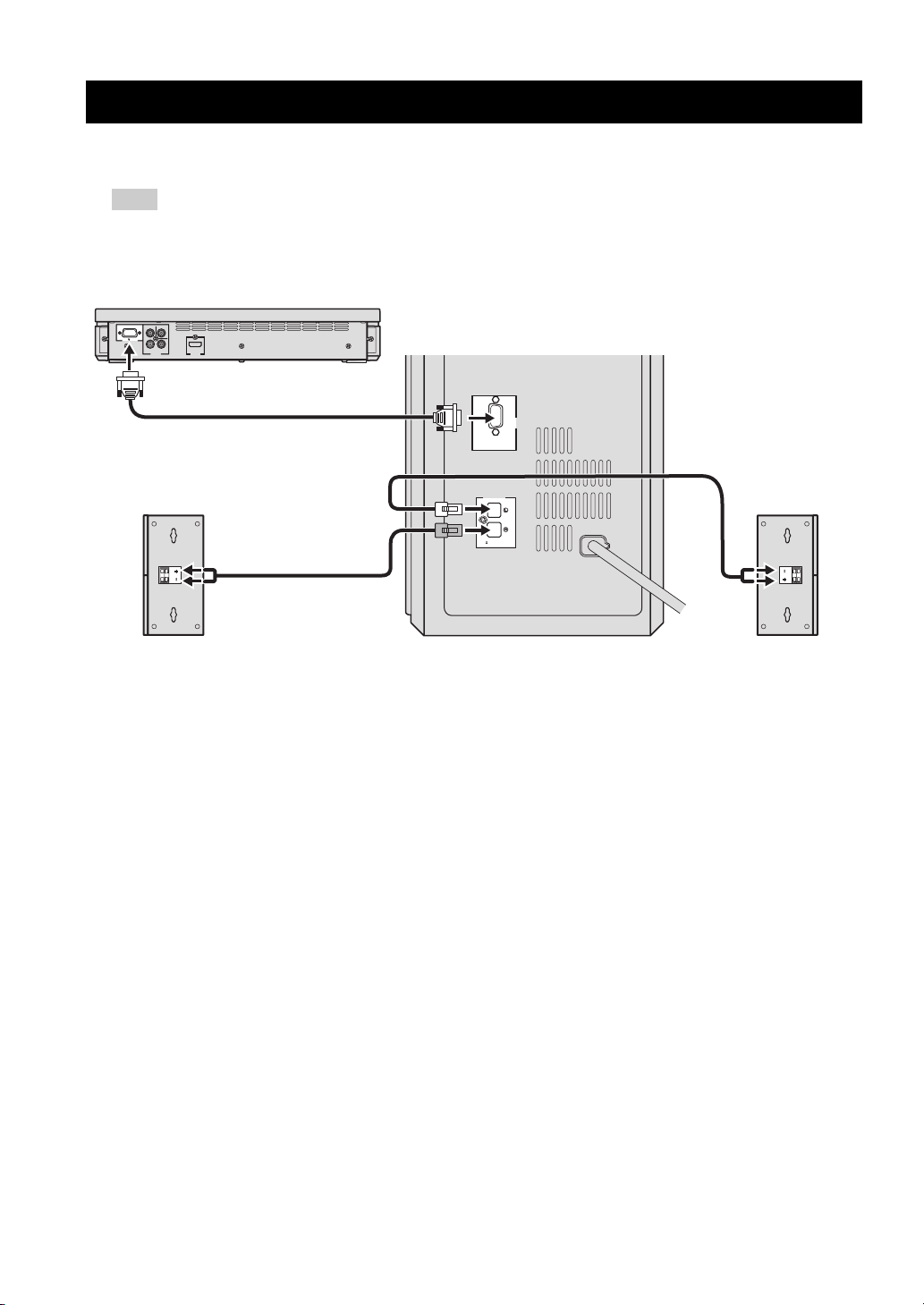
SYSTEM CONNECTIONS
■ Connecting the speakers
Note
Do not connect the power cable of the subwoofer/system control into an AC outlet until all cable connections are
completed.
DVD controller
NS-PSW700
VIDEO
Y
SYSTEM
P
B
PR
CONNECTOR
COMPONENT
VIDEO
HDMI
OUTPUT
OUTPUT
Subwoofer/system control
SYSTEM
CONNECTOR
DVR-700
SPEAKERS
SPEAKER
IMPEDANCE
:
6 MIN.
MAINS
Speaker (R)
Speaker (L)
14 En
Page 19
Connecting the speakers and
subwoofer/system control
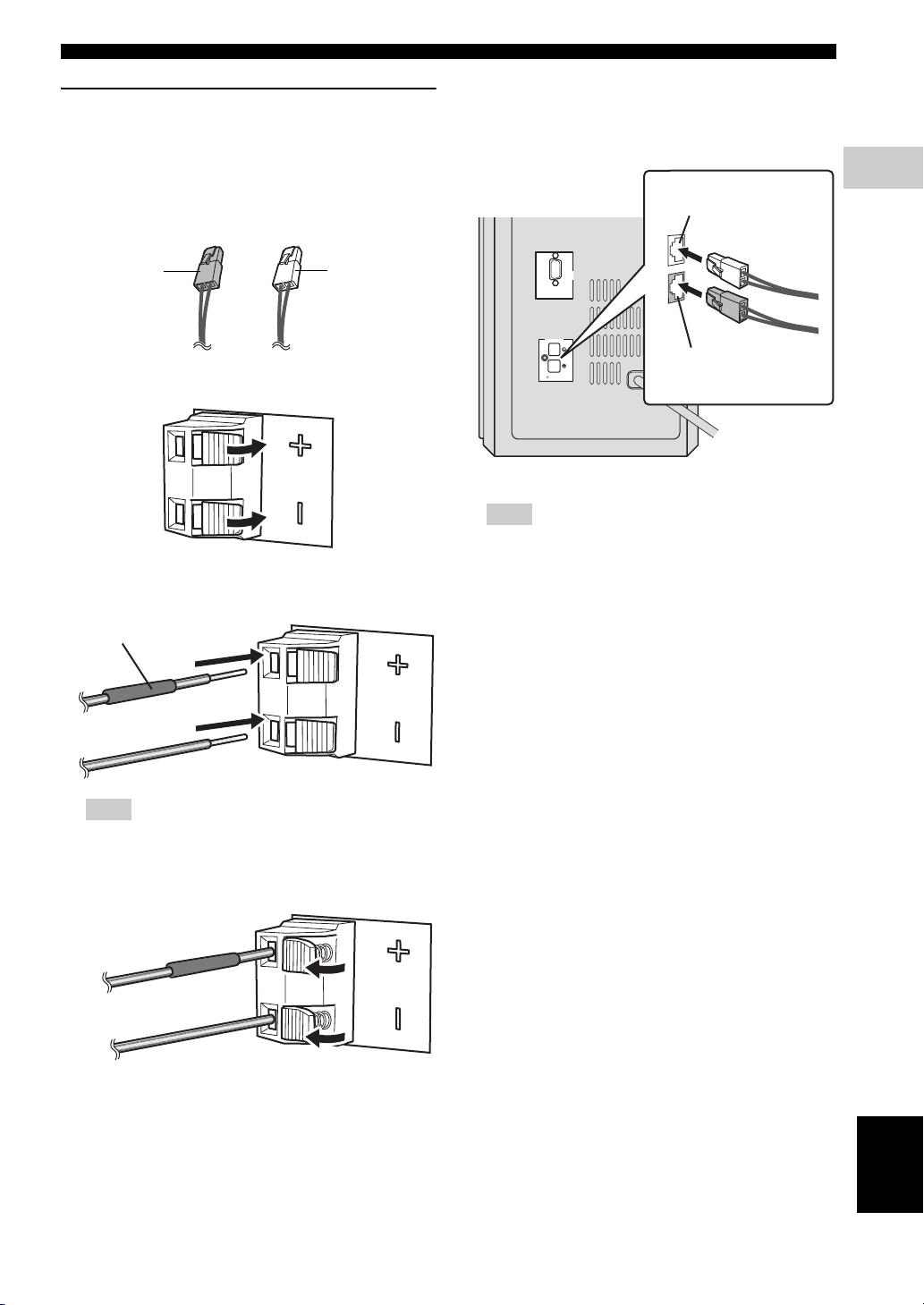
Connecting the speakers
Confirm the plug colors of the speaker cables.
– Speaker cable with white plug: for speaker (L)
– Speaker cable with red plug: for speaker (R)
SYSTEM CONNECTIONS
Connecting the subwoofer/system control
1 Insert the speaker cable plug until you hear a click
sound.
from speaker (L)
2
CONNECTIONS
for speaker (R):
Red plug
for speaker (L):
White plug
1 Push down the knob of the speaker terminal.
2 Insert the stripped speaker cable into the hole on the
speaker terminal.
Red tube
SYSTEM
CONNECTOR
DVR-700
SPEAKERS
from speaker (R)
SPEAKER
IMPEDANCE
:
6 MIN.
MAINS
Note
Make sure that the cable plugs are connected to the
subwoofer/system control terminals of the same color.
2 Use the same procedure to connect the other speaker
cable.
Note
Connect the cable with red tube to the positive
terminal, and the other cable to the negative terminal.
3 Release the knob of the speaker terminal.
English
15 En
Page 20
SYSTEM CONNECTIONS
E
■ Connecting the DVD controller and the subwoofer/system control
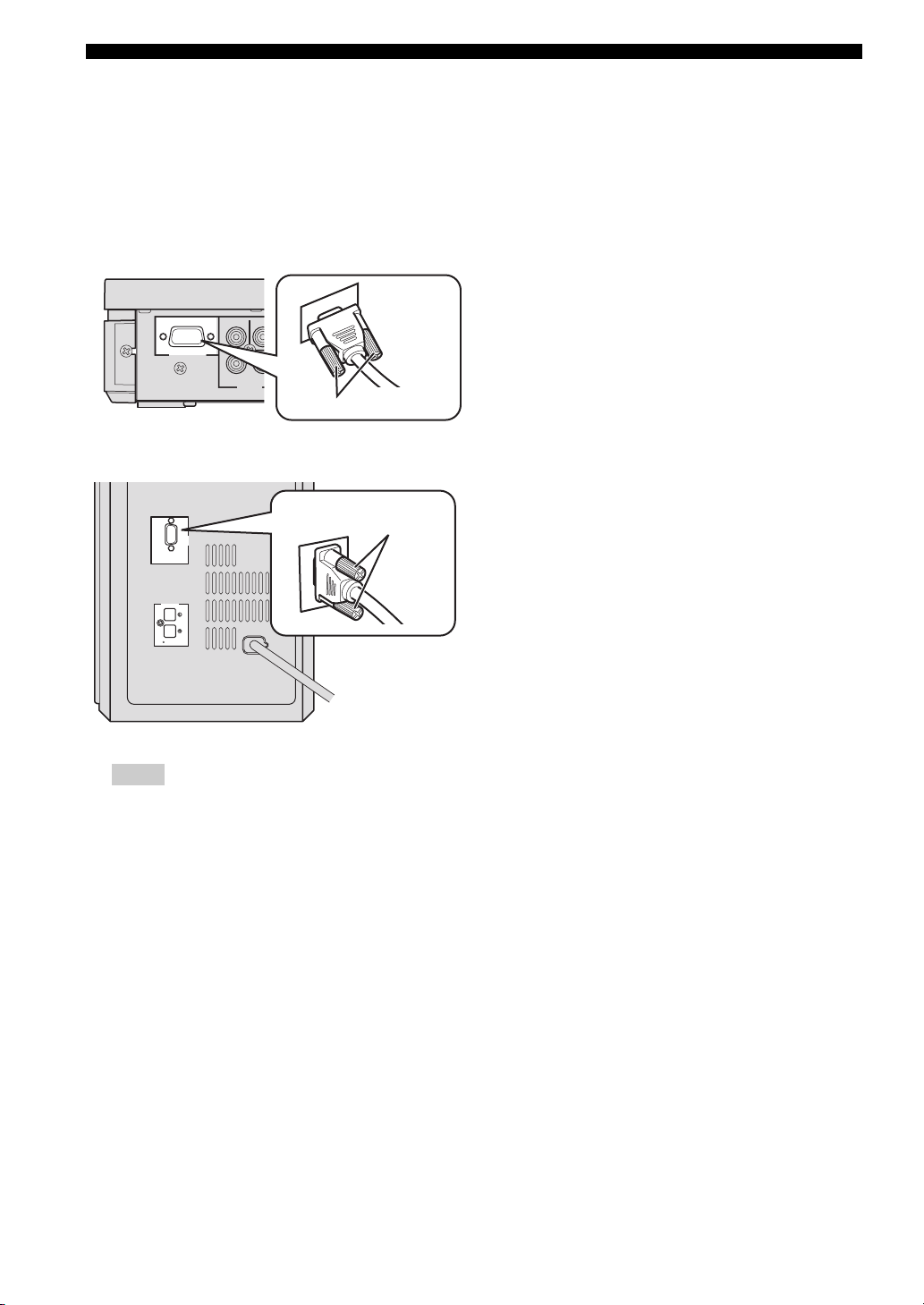
Connect the SYSTEM CONNECTOR terminal at the rear
of the subwoofer/system control to the SYSTEM
CONNECTOR terminal at the rear of the DVD controller
using the system control cable.
NS-PSW700
SYSTEM
CONNECTOR
P
Y
B
COMPONENT
VIDEO
OUTPUT
VID
NS-PSW700
Tighten the screws.
Tighten the screws.
DV
MAINS
SYSTEM
CONNECTOR
SPEAKER
:
DVR-700
SPEAKERS
6 MIN.
IMPEDANCE
SYSTEM
CONNECTOR
Notes
– Make sure that the system control cable is correctly
connected. Improper connections may damage the
system due to a short-circuit.
– To prevent unwanted noise, do not place the
subwoofer too close to the DVD controller, AC
power adaptor, TV or other sources of radiation.
– Do not insert the Power cable to an AC outlet until
all connections are completed.
16 En
Page 21
OTHER CONNECTIONS
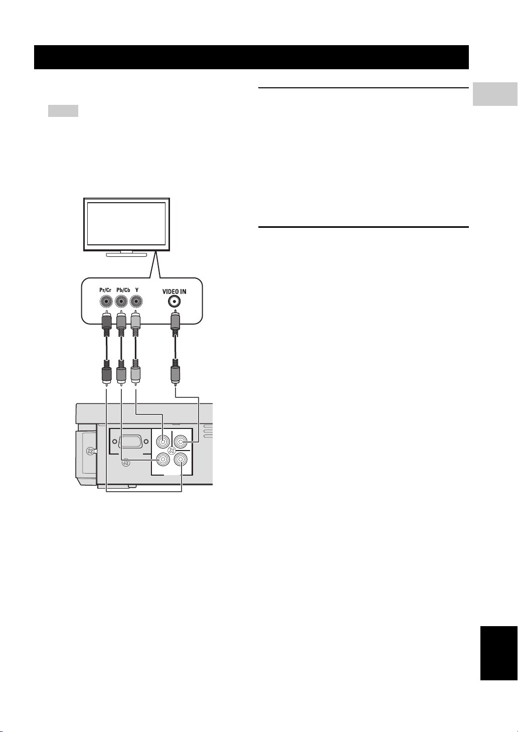
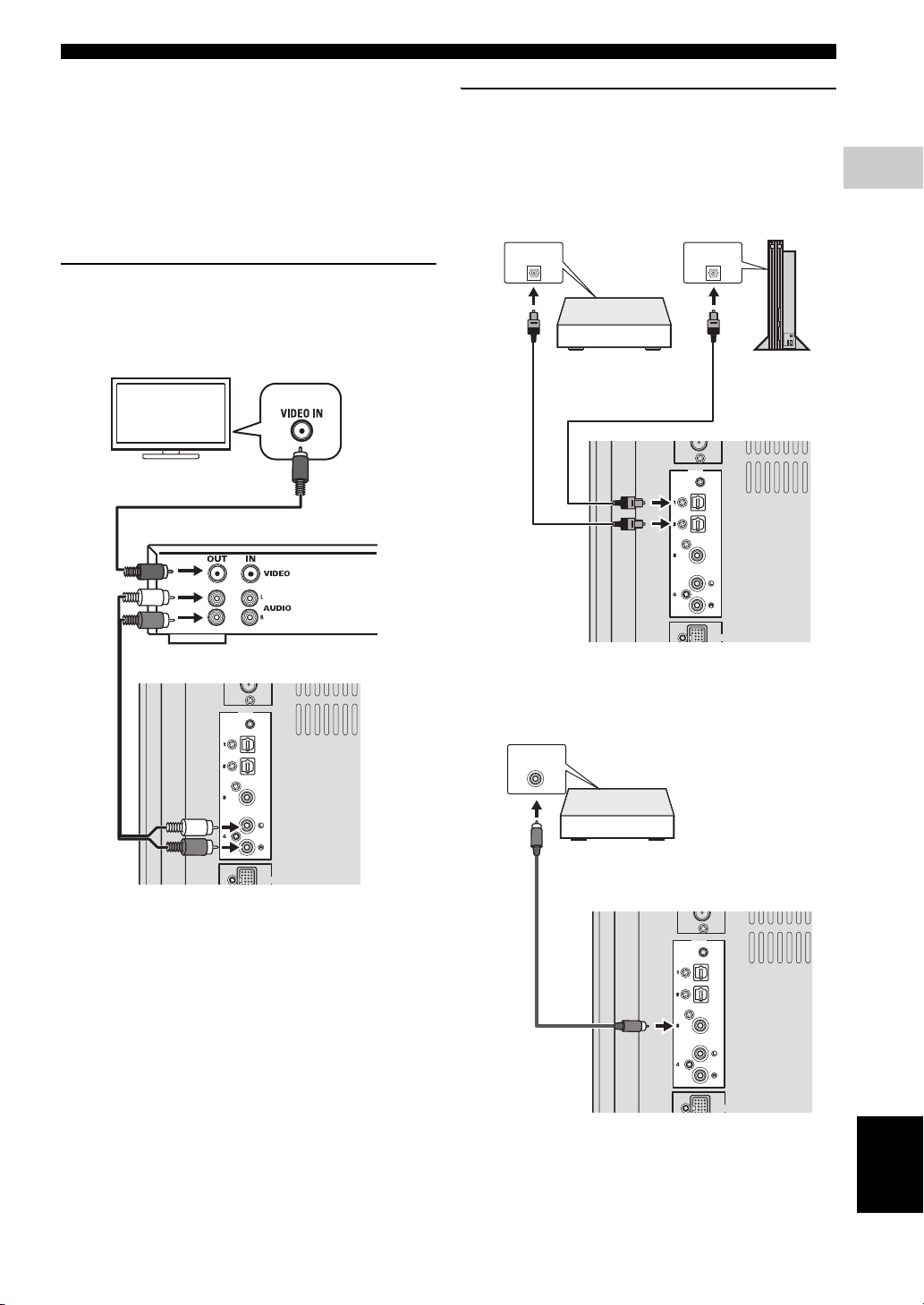
■ Connecting a TV
Notes
– You only need to make one video connection from
the following options (A or B), depending on the
capabilities of your TV.
– Do not connect the power cables until all cable
connections are completed.
TV
<A> <B>
COMPONENT VIDEO OUTPUT jacks
<A>
Use the component video cables (Green/Blue/Red, not
supplied) to connect the DVD controller’s Y P
B PR jacks
to the corresponding component video input jacks (or the
Y PB/CB PR/CR YUV jacks) on your TV.
Progressive scan video quality is only available when
using Y P
B PR in conjunction with a progressive scan TV.
To activate the progressive scan function, refer to
“Selecting the output type for COMPONENT VIDEO
OUTPUT jacks” on page 24.
VIDEO OUTPUT jack <B>
Use the Video pin cable (yellow-supplied) to connect the
DVD controller’s VIDEO OUTPUT jack to the video
input jack (or A/V In/Video In/Composite/Baseband jack)
on your TV.
2
CONNECTIONS
DVD controller
NS-PSW700
SYSTEM
CONNECTOR
P
Y
B
COMPONENT
VIDEO
OUTPUT
VIDEO
PR
English
17 En
Page 22
OTHER CONNECTIONS
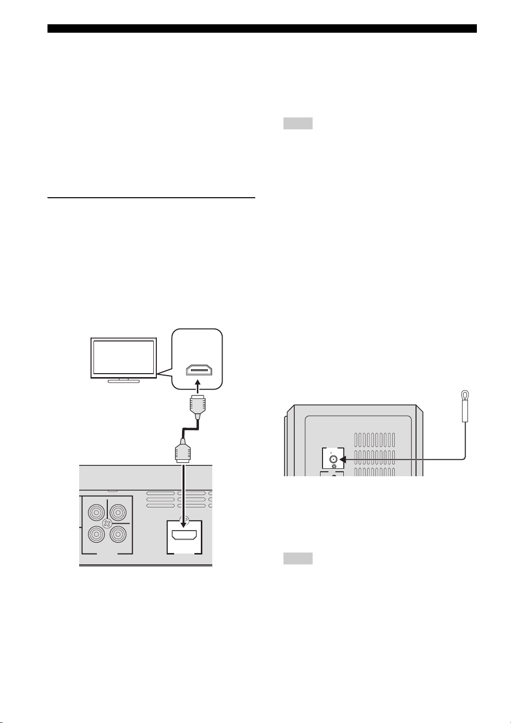
■ Connecting an HDMI component
HDMI (High-Definition Multimedia Interface) is the first
industry-supported, uncompressed, all-digital A/V (audio/
video) interface.
By connecting to an HDMI component (such as a TV),
you can enjoy standard, enhanced or high-definition video
as well as digital audio using a single cable.
When used in combination with HDCP (High-bandwidth
Digital Content Protection), HDMI provides a secure
audio/video interface that meets the security requirements
of content providers and system operators.
For further information on HDMI, visit the HDMI website
at “http://www.hdmi.org/”.
Viewing and Listening to playback
from an HDMI component
To output an HDMI signal, you need to configure the
settings manually. It is necessary to prepare in advance to
output an HDMI signal.
1 Set the system to standby mode.
2 Connect the HDMI terminals on your HDMI
compatible device and the DVD controller using a
commercially available HDMI cable.
TV
HDMI
IN
4 To set the video output according to the HDMI
compatible device, refer to “Video Output” on
page 38 to access the DVD setup menu, and then set
the two items under Video output in the system menu.
– HDMI Resolution
– HDMI Color
Notes
– This unit is designed to connect to HDMI
compatible devices. If you connect to the DVI
component, the system may not operate correctly.
– The DVD controller is not compatible with HDCP-
incompatible HDMI or DVI components.
– You need a commercially available HDMI/DVI
conversion cable when you connect the DVD
controller to other DVI components.
– If you connect the system to the DVI component
with a HDMI/DVI conversion cable, the HDMI
terminal of the DVD controller does not output any
audio signals.
– Do not disconnect or connect the HDMI cable from
the DVD controller or turn off the power of the
HDMI/DVI component connected to the HDMI
OUTPUT terminal of the DVD controller while
data is being transferred. Doing so may disrupt
playback or cause noise.
– PCM signal downmixed to two channels can be
output from the HDMI output terminal.
■ Connecting the FM antenna
DVD controller
VIDEO
Y
B
P
COMPONENT
VIDEO
OUTPUT
P
R
HDMI
OUTPUT
3 To output an audio signal from the DVD controller to
the HDMI compatible device, refer to “System menu”
on page 57.
After doing the settings, set the DVD controller to
standby mode, and then turn on the system again.
18 En
ANTENNA
FM
UNBAL
.
75
INPUT
Subwoofer/system control
Connect an indoor FM antenna to the ANTENNA
terminal. Extend the FM antenna and fix its ends to the
wall.
For better FM stereo reception, connect an external FM
antenna.
Notes
– Adjust the position of the antenna for optimal
reception.
– Position the antenna as far as possible from your
TV, VCR or other sources of radiation to prevent
unwanted interference.
Page 23
■ Connecting external AV components
If you connect external AV equipment, such as a VCR or
cassette deck, to the audio input terminal on the
subwoofer/system control, you can listen to those audio
sources on the system.
This section provides some examples of VCR and digital
AV equipment connections.
Connecting analog AV components
Connect the DVD controller and external AV equipment
as shown in the illustration.
OTHER CONNECTIONS
Connecting digital AV components
Connect the subwoofer/system control and external AV
equipment as shown in the illustration.
When connecting to optical type digital AV
components
OPTICAL
DIGITAL OUTPUT
OPTICAL
DIGITAL OUTPUT
2
CONNECTIONS
TV
Subwoofer/system control
INPUT
VCR (for example)
OPTICAL
OPTICAL
COAXIAL
ANALOG
DOCK
Digital audio
component
INPUT
OPTICAL
OPTICAL
COAXIAL
ANALOG
Game
console
DOCK
Subwoofer/system control
When connecting to coaxial type digital
AV components
COAXIAL
DIGITAL OUTPUT
Digital audio
component
INPUT
OPTICAL
OPTICAL
COAXIAL
ANALOG
DOCK
English
19 En
Page 24
OTHER CONNECTIONS
OPTICAL
OPTICAL
Y
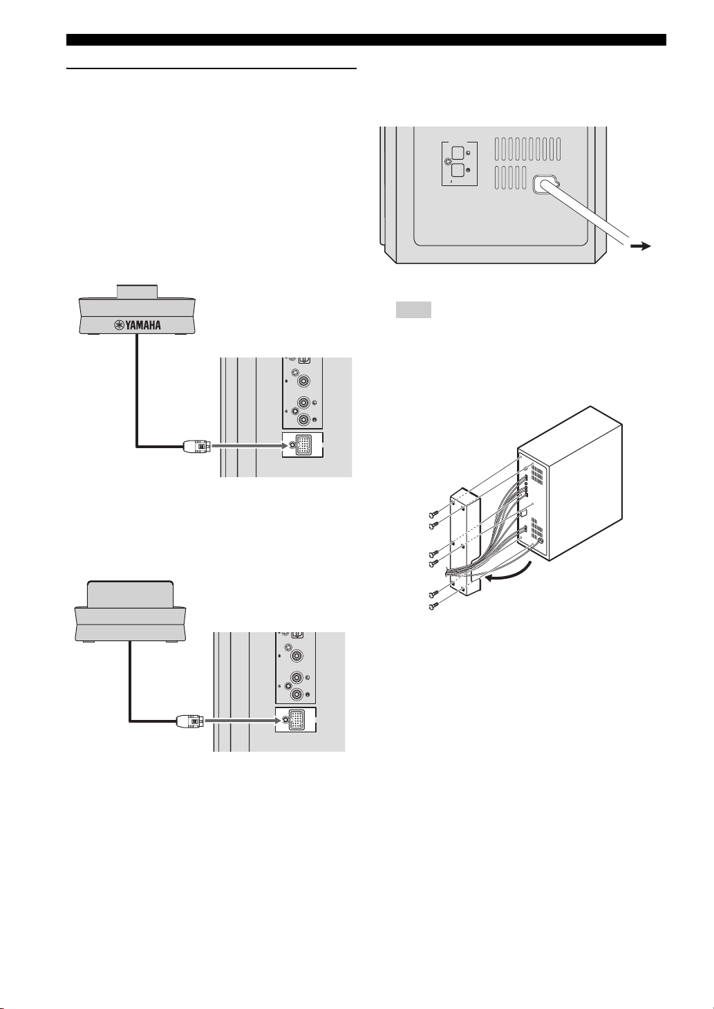
Connecting optional equipment
The system is equipped with the DOCK terminal, which
allows you to connect the Yamaha iPod universal dock
(such as YDS-10 or YDS-11, sold separately) or Yamaha
Bluetooth wireless audio receiver (such as YBA-10, sold
separately). Connect the optional equipment to the DOCK
terminal of the subwoofer/system control using its
dedicated cable.
When connecting the Yamaha iPod
universal dock
Yamaha iPod universal dock
(such as YDS-10 or YDS-11, sold separately)
COAXIAL
ANALOG
■ Connecting the power cable
After you have made all connections, connect the power
cable of the subwoofer/system control.
SPEAKERS
SPEAKER
IMPEDANCE
:
6 MIN.
Hint
You can attach or detach the cover according to your
preference after you have made all connections.
Attach the cover to the rear panel of subwoofer/system
control using the 6 supplied screws as shown.
MAINS
To AC
outlet
DOCK
When connecting the Yamaha Bluetooth
wireless audio receiver
amaha Bluetooth wireless audio receiver
(such as YBA-10, sold separately)
COAXIAL
ANALOG
DOCK
20 En
Page 25
PREPARATION
GETTING STARTED
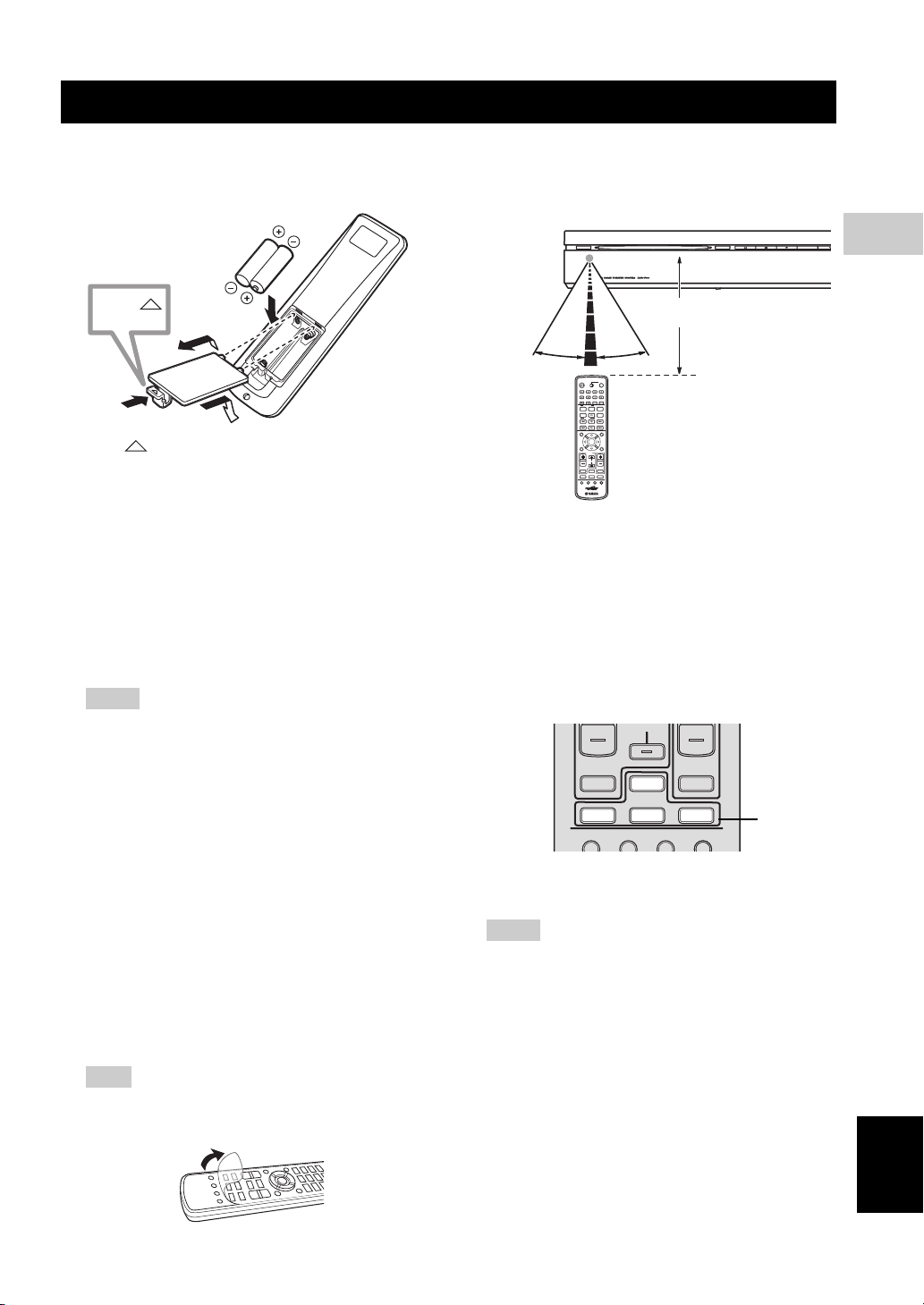
■ Inserting batteries into the remote control
Press
1
1 Press on the battery cover and open the cover.
2 Insert the two supplied batteries (AA, R6, UM-3) into
the battery compartment.
Insert the batteries according to the polarity markings
(+ and –).
3 Close the battery cover.
Replacing the batteries
If the batteries run low, the effective operation distance of the
remote control decreases considerably. If this happens,
replace the batteries with two new ones as soon as possible.
Notes
– Do not use an old battery together with new one.
– Do not use different types of batteries (for
example, alkaline and manganese) together. Each
type of battery has its own characteristics even if
they are similar in shape.
– If the batteries run out, immediately remove them
from the remote control to prevent an explosion or
acid leak.
– Dispose of the batteries according to the regional
regulations.
– If a battery starts leaking, dispose of it
immediately.
Be careful not to let leaking battery acid come into
contact with your skin or clothing. Before inserting
new batteries, wipe the compartment clean.
– Replace the batteries within two minutes to
preserve the preset code in the remote control.
Hint
Remove the transparent sheet before using the remote
control.
2
3
■ Using the remote control
Use the remote control within 6 m of the DVD controller
and point it toward the remote control sensor.
STANDBY / ON
30˚ 30˚
ENTER
/
STB
TV
CH
Within 6 m
EJECT
Basic operation of the remote control
1 Use the Input selection buttons on the remote control
to select the input source you wish to control (for
example DVD/USB).
→ The selected source appears in the front panel
display.
When the button contains several input sources such
as DVD/USB and INPUT 1-4 buttons, the input
source switches each time you press the button.
CH
TV VOL
TV INPUT
/
USB INPUT 1-4
DVD
POSITION
AREA SOUND TEST
2 Operate the desired function (for example, h or b
/ a).
Notes
– Be careful not to spill liquid on the remote control.
– Be careful not to drop the remote control.
– Do not leave the remote control in the following
places:
– hot or humid places, such as near a heater or in a
bathroom
– extremely cold places
– dusty places
– To operate your TV with the remote control, you
need to set the preset code.
Refer to “Setting the preset code” on page 58 for
how to change the preset code.
VOLUME
TUNER MUTE
DOCK
Input
selection
buttons
3
PREPARATION
English
21 En
Page 26

GETTING STARTED
■ Turn on the system
Press STANDBY/ON on the DVD controller or the
remote control.
The LED indicators beside the disc loading slot light up
when the system is turned on.
STANDBY/ON
STANDBY / ON
STANDBY
MOVIE
STEREO
Light up
/
ON
FUNC.
MUSIC
ENHANCER
WP87020DVX-700
TV STB
10KEY
NIGHT
POWER
GAMESPORTS
SLEEP
EJECT
22 En
Page 27
■ Setting the video input/output
Notes
– Make sure that you have completed all the
necessary connections (Refer to “Connecting a
TV” on page 17).
– If the settings you have selected are not
appropriate, you can reset DVD settings to the
initial factory settings (Refer to “System menu” on
page 57).
1 Press DVD/USB repeatedly until “DVD” appears in
the front panel display.
2 Turn on the TV and set to the correct video-in
channel.
→ You should see the background screen on the TV.
– Usually this channel is between the lowest and
highest channels and may be called FRONT, A/V
IN or VIDEO. See your TV manual for more
details.
– Or, you may go to channel 1 on your TV, then
press the Channel down button repeatedly until you
see the Video In channel.
– Or, the TV remote control may have a button or
switch that chooses different video modes.
GETTING STARTED
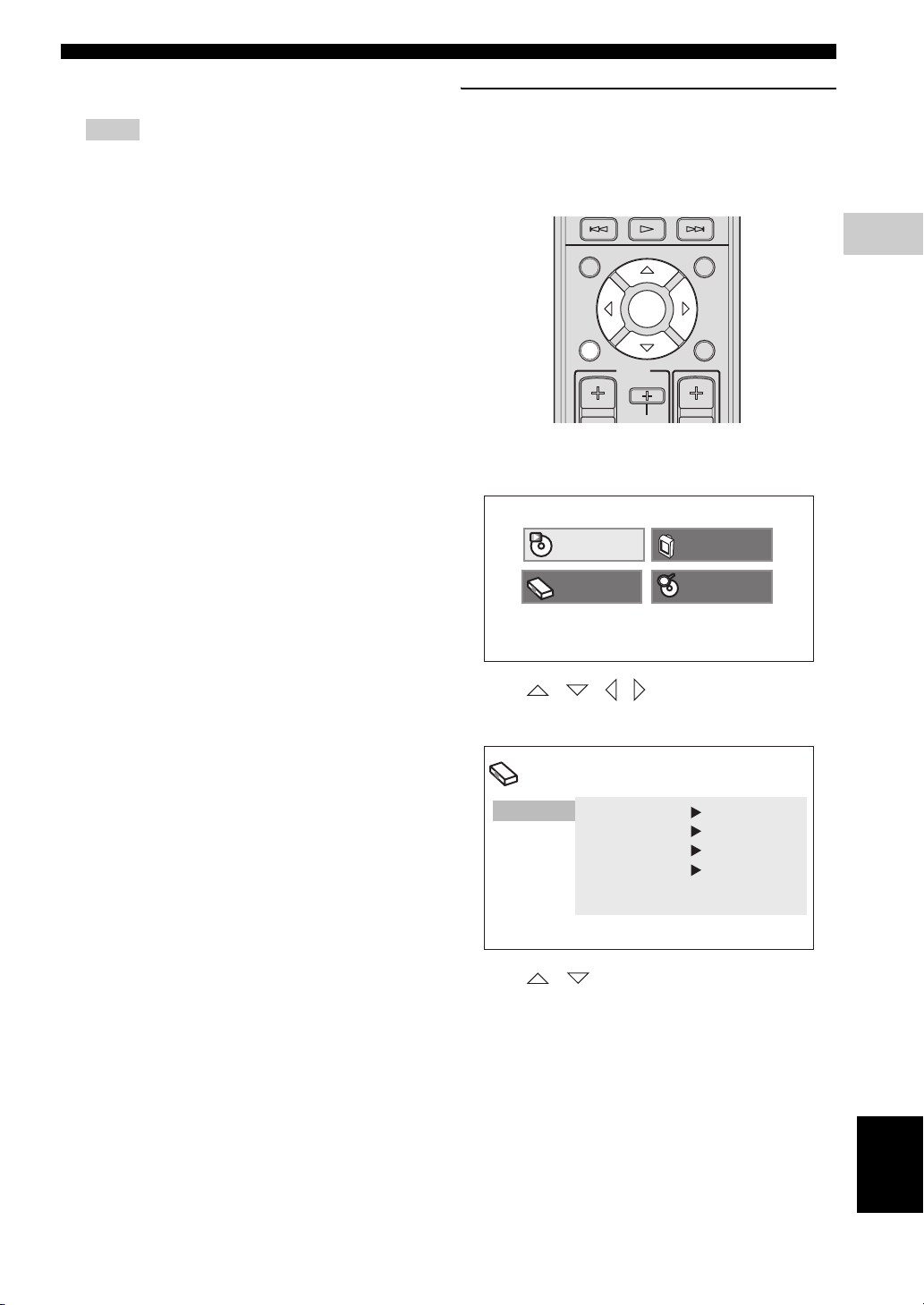
Setting the TV display
Set the aspect ratio of the DVD controller according to the
TV you have connected. The format you select must be
available on the disc. If it is not, the TV display setting
will not affect the picture during playback.
TOP MENU
PRESET
INFO.
A-E A-E
SETUP RETURN
ENTER
TV
/
STB
1 Press SETUP on the remote control.
DVD setup menu is displayed on the screen.
Play Mode
Initial Setting
MENU
CODE SET
CH
Video Adjust
Disc Navigator
3
PREPARATION
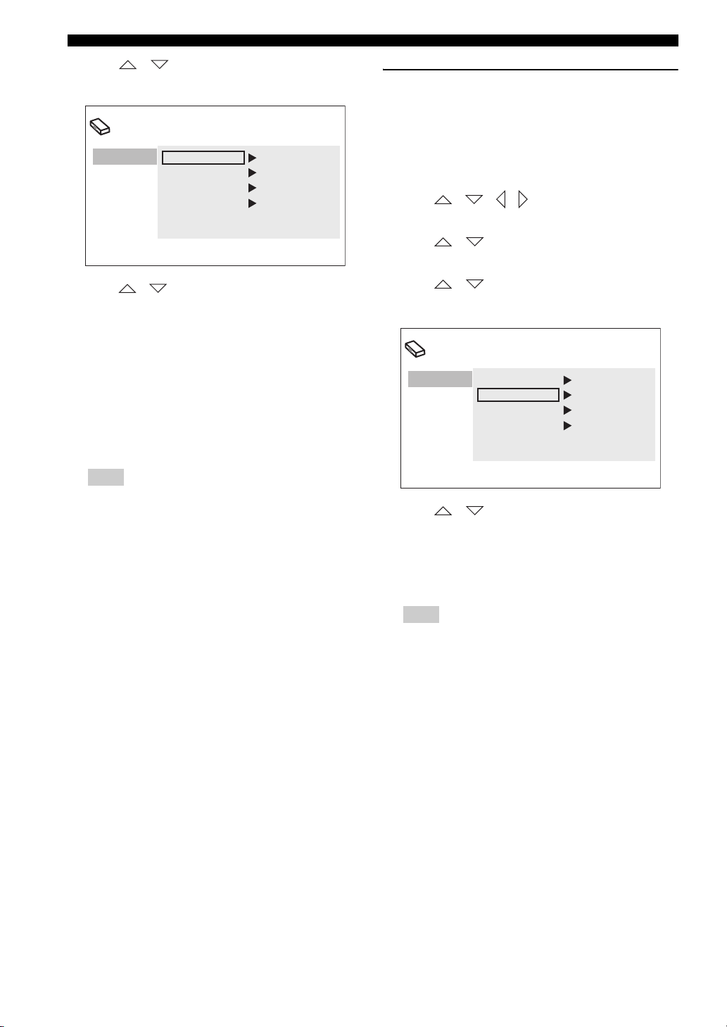
2 Press / / / on the remote control to
highlight [Initial Settings], and then press ENTER.
Initial Setting
Video Output
Language
Display
Options
TV Screen 4:3 (Letter Box)
Component Out Interlace
HDMI Resolution
HDMI Color Component
720x480p
3 Press / on the remote control to highlight
[Video Output], and then press ENTER.
English
23 En
Page 28
GETTING STARTED
4 Press / on the remote control to highlight
[TV Screen], and then press ENTER.
Initial Setting
Video Output
Language
Display
Options
TV Screen 4:3 (Letter Box)
Component Out Interlace
HDMI Resolution
HDMI Color Component
720x480p
Selecting the output type for
COMPONENT VIDEO OUTPUT jacks
To use progressive display function, connect to a TV,
which has that function, via COMPONENT VIDEO
OUTPUT jacks.
1 Press SETUP on the remote control.
2 Press / / / on the remote control to
highlight [Initial Settings], and then press ENTER.
3 Press / on the remote control to highlight
[Video Output], and then press ENTER.
5 Press / on the remote control to highlight one
of the options below, and then press ENTER.
4:3 (Letter Box)
Select this if you have a conventional TV. In this case, a
wide picture with black bar on the upper and lower
portions of the TV screen will be displayed.
4:3 (Pan&Scan)
Select this if you have a conventional TV and want both
sides of the picture to be trimmed or formatted to fit your
TV screen.
Note
If the disc does not support an aspect ratio of 4:3
(Pan&Scan), the content is displayed in 4:3 (Letter
Box).
16:9 (Wide)
Select this if you have a wide-screen TV.
16:9 (Compressed)
Select this if a wide-screen TV is connected to the DVD
controller with an HDMI cable, and set HDMI Resolution
to either [1920 x 1080p], [1920 x 1080i], or [1280 x
720p]. When playing back a content whose aspect ratio is
4:3, black bars cover the sides of the screen.
4 Press / on the remote control to highlight
[Component Out], and then press ENTER.
Initial Setting
Video Output
Language
Display
Options
TV Screen 4:3 (Letter Box)
Component Out Interlace
HDMI Resolution
HDMI Color Component
720x480p
5 Press / on the remote control to highlight
[Progressive] / [Interlace], and then press ENTER.
6 When the confirmation screen appears, press ENTER
again.
To cancel the setting, press RETURN.
Note
Do not select [Progressive] if your TV does not have a
progressive display function.
If your TV is also connected via HDMI OUTPUT
terminal, the system may ignore this setting and
output the progressive signal from COMPONENT
VIDEO OUTPUT jacks.
24 En
Page 29
■ Setting language preferences
You can select your preferred language settings so that
this controller will automatically switch to your preferred
language whenever you load a disc. If the language
selected is not available on the disc, the disc’s default
setting language will be used instead. The OSD (on-screen
display) language for the DVD setup menu will remain as
you set it, regardless of various disc languages.
On-screen display (OSD) language
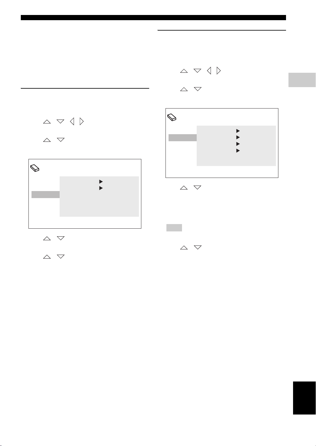
1 Press SETUP on the remote control.
DVD setup menu appears on the screen.
2 Press / / / on the remote control to
highlight [Initial Settings], and then press ENTER.
3 Press / on the remote control to highlight
[Display], and then press ENTER.
Initial Setting
GETTING STARTED
Audio, Subtitle and Disc menu
languages
1 Press SETUP on the remote control.
DVD setup menu appears on the screen.
2 Press / / / on the remote control to
highlight [Initial Settings], and then press ENTER.
3 Press / on the remote control to highlight
[Language], and then press ENTER.
Initial Setting
Video Output
Language
Display
Options
Audio Language English
Subtitle Language English
DVD Menu Lang. English
Subtitle Display On
3
PREPARATION
Video Output
Language
Display
Options
OSD Language English
Angle Indicator
On
4 Press / on the remote control to highlight
[OSD Language], and then press ENTER.
5 Press / on the remote control to select a
language, and then press ENTER.
4 Press / on the remote control to highlight the
item below, and then press ENTER.
– Audio Language
– Subtitle Language
– DVD Menu Language
Hint
Refer to page 40 for the other items.
5 Press / on the remote control to select a
language, and then press ENTER.
25 En
English
Page 30
BASIC OPERATIONS
DISC OPERATION
This unit is designed for use with DVD, CD, Video CD,
and Super Video CD, as well as DivX® files and WMV
files recorded on CD-R or DVD-R/DVD+R.
IMPORTANT!
– DVD discs and players are designed with regional
restrictions. Before playing a disc, make sure that
the disc is for the same zone as your DVD
controller.
– Do not insert any objects other than discs into the
disc loading slot. Doing so may cause the DVD
controller to malfunction.
– Depending on the disc, some functions may be
prohibited.
– This unit is not compatible with 8-cm discs.
■ Playing discs
1 Turn on the system.
2 Press DVD/USB repeatedly until “DVD” appears in
the front panel display.
3 Turn on the TV power and set to the correct Video-in
channel (Refer to “Setting the video input/output” on
page 23).
→ You should see the background screen on the TV.
4 Insert the disc into the disc loading slot.
STANDBY / ON
5 Press h to start playback.
→ If a disc menu appears on the TV, refer to “Using
the disc menu (DVD only)” on page 28.
→ If the disc is locked by parental lock function, you
must enter your 4-digit password (Refer to “Parental
Lock” on page 41).
Note
If you do the operation that is not available during
playback, a message “This operation can’t be
performed.” or “Depending on the disc, this operation
may be prohibited.” appears.
EJECT
Playing DivX® video/WMV files
DivX® video file
This unit can play DivX
DVD-R/-RW, DVD+R/+RW discs. By default they will
be played in alphabetical order. The supported files are
shown below.
– Plays all versions of DivX
®
6) with enhanced playback of DivX®
DivX
media files and the DivX
– The following filename extensions are supported
“.avi” and “.divx”.
Displaying external subtitle files
The font sets listed below are available for external
subtitle files. You can see the proper font set on-screen
by setting [Subtitle Language] to match the subtitle
file.
Group 1
Group 2
Group 3
Group 4
Group 5
– Some external subtitle files may be displayed
incorrectly or not at all.
– For external subtitle files, the following subtitle
format filename extensions are supported:
“.srt”, “.sub”, “.ssa”, “.smi”
– The filename of the movie file has to be
repeated at the beginning of the filename for the
external subtitle file.
– The number of external subtitle files which can
be switched for the same movie file is limited to
a maximum of 10.
®
videos recorded on CD-R/RW,
®
video (including
®
media format.
Albanian (sq), Basque (eu), Catalan (ca),
Danish (da), Dutch (nl), English (en),
Faroese (fo), Finnish (fi), French (fr),
German (de), Icelandic (is), Irish (ga),
Italian (it), Norweigian (no),
Portuguese (pt), Rhaeto-Romanic (rm),
Scottish (gd), Spanish (es), Swedish (sv)
Albanian (sq), Croatian (hr), Czech (cs),
Hungarian (hu), Polish (pl),
Romanian (ro), Slovak (sk),
Slovenian (sl)
Bulgarian (bg), Byelorussian (be),
Macedonian (mk), Russian (ru),
Serbian (sr), Ukrainian (uk)
Hebrew (iw), Yiddish (ji)
Turkish (tr)
26 En
Page 31

DISC OPERATION
WMV file
WMV content can be encoded by using Windows Media
Encoder.
The supported files are shown below.
– The DVD controller is compatible with WMV9
files that are encoded by using the Windows Media
Encoder 9 Series, with “.wmv” as an filename
extension.
– Compatible with size under 720 x 576 pixels/720 x
480 pixels.
– The available maximum bit rate is about 2 to
3 Mbps. The maximum bit rate varies depending
on the encode method.
– Advanced Profile is not supported.
– DRM-Protected video files are not played in the
DVD controller.
■ Basic playback controls
/
ON
FUNC.
MUSIC
ENHANCER
AUDIO DELAY
BLUETOOTH
PTY SEEK
AUTO/
WP87020DVX-700
TV STB
SUBTITLE
START
MANUAL
PRESET
10KEY
NIGHT
ZOOM
POWER
GAMESPORTS
SLEEP
ON SCREEN
ANGLE
CLEAR
FREQ / TEXT
MEMORY
MENU
When using Numeric
keypad 0-9
Switch FUNC./10KEY to
10KEY
Numeric keypad 0-9
STANDBY
MOVIE
STEREO
DISP. MODE
ON OFF
AUDIO
PLAY MODE
MODE
PRESET/ TUNE
TOP MENU
To pause playback
During playback, press e.
– To resume normal playback, press h.
To stop playback
Press s.
To select track/chapter
Press b / a to select previous/next track or chapter.
You can enter a track/chapter number using Numeric
keypad 0-9.
To search backward/forward
Press w / f.
– To resume normal playback, press h.
– When searching, press w / f again to increase the
search speed. (DVD, CD, and VideoCD only)
To playback in slow motion
During pause, press and hold f to play back in slow
motion. To resume normal playback, press h.
During pause, press and hold w to play back in reverse
slow motion. (DVD only)
4
BASIC OPERATIONS
Hint
During slow motion playback, press w / f to
change the playback speed. (DVD, CD, and Video CD
only)
To advance by frame
During pause, press f to advance by frame. To resume
normal mode, press h.
During pause, press w to reverse by frame. (DVD
only)
To adjust the volume level
Press VOLUME +/– on the remote control or VOLUME
u / d on the DVD controller. The volume level appears
in the front panel display.
27 En
English
Page 32

DISC OPERATION
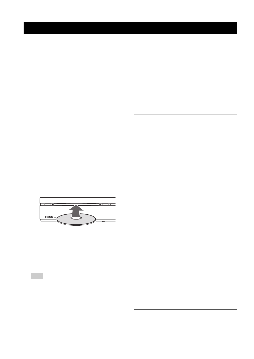
■ Ejecting a disc
Press s to stop disc playback, and then press EJECT on
the DVD controller.
EJECT
STANDBY / ON
Note
Do not push the ejected disc when reloading it. To
reload the ejected disc, press EJECT, or remove the
disc from the disc loading slot fully, then insert it to
the disc loading slot once again.
EJECT
■ Using the disc menu (DVD only)
To display the disc menu
Press TOP MENU to display the top-level disc menu.
Press MENU to return to the main menu. The same menu
as the top-level disc menu may appear depending on the
disc.
Hint
– Depending on the disc, a menu may appear on the
TV screen once you load a disc.
– The disc menu is displayed when you press TOP
MENU during playing DivX
Note
Depending on the disc, these menus do not appear on
the TV screen.
To select a playback feature or item
Press / / / on the remote control, then press
ENTER to start playback.
You can also specify the number to select a feature or
item.
To enter a number, switch FUNC./10KEY to 10KEY.
®
files. (If available)
■ Playback control (PBC) (Video CD only)
Some Video CD/super Video CD discs are compatibility
with PBC function.
PBC playback allows you to play Video CDs
interactively, following the menu on the display.
To display the PBC menu
When you insert a video CD or super video CD with PBC
function and press h, playback starts with the function.
During playback, press RETURN to display the menu.
Press b / a to display the other menu on the
previous/next page.
To select a track in PBC menu
To select a track, switch FUNC./10KEY to 10KEY, enter
the number, and then press ENTER.
Note
To disable PBC, press s twice, then press a. You
can enter a track number using Numeric keypad 0-
9 instead of pressing a.
To enable PBC again, press s twice, then press h to
play back.
■ Changing soundtrack language
While playing a DVD with multiple language
soundtracks, press AUDIO repeatedly to select the
language.
Notes
– If you cancel the resume mode or eject the disc, the
language gets back to the default setting.
– When playing a Video CD, it switches 1/L (Left)
and 2/R (Right).
– You can change the soundtrack language by
pressing AUDIO during playing DivX
files. (if available)
– Depending on the disc, you can change the
soundtrack language only in the disc menu.
®
video
28 En
Page 33

DISC OPERATION
■ Changing subtitle language
This operation works only on DVDs with multiple subtitle
languages. You can change the language you want while
playing a DVD.
Press SUBTITLE repeatedly to select a language from the
various subtitle languages.
Notes
– If you cancel the resume mode or eject the disc, the
language gets back to the default setting.
– Depending on the disc, you can change the
language only in the disc menu.
– You can change the subtitle language by pressing
SUBTITLE during playing DivX
available)
®
video files. (if
■ Resuming playback from the last stopped point
With the exception of VR format DVD-R/-RW discs,
when you stop playback of a DVD, CD, or Video CD/
Super video CD or DivX
“RESUME” appears in the front panel display indicating
that you can resume playback again from that point.
With DVDs and Video CD/Super video CDs, if you eject
the disc in the DVD controller after stopping playback, the
last play position is stored in memory. If the next disc you
load is the same one, “Last Memory” appears and
playback will resume. For DVD-Video discs, the system
stores the play position of the last five discs. When one of
these discs is next loaded, you can resume playback.
®
video/WMV discs,
■ Displaying disc information
Press ON SCREEN to display track, chapter and title
information. Press ON SCREEN repeatedly to select the
information.
■ Zooming in
This function allows you to enlarge the picture double or
quadruple of the original size. While playing a disc, press
ZOOM once to double or twice to quadruple the size. You
can move the zoom point using / / / .
Press ZOOM one more time to return to the original size.
4
BASIC OPERATIONS
Hints
– To clear the resume point, press s again while
“RESUME” is displayed.
– If you don’t need the Last Memory function when
you stop a disc, you can press EJECT to stop
playback and eject the disc.
Notes
– Resume and Last Memory functions may not work
with some discs.
– As for CD and movie files (DivX
resume point is cleared when the disc is ejected or
the input is changed.
®
/WMV), the
■ Viewing from another angle
If the disc contains sequences recorded from different
camera angles, the angle mark appears on the screen.
Press ANGLE repeatedly to select the desired angle.
Hint
You can hide the angle mark (Page 41).
English
29 En
Page 34

DISC OPERATION
■ Advanced operation
When playing discs, you can use advanced operations
such as repeat playback and programming playback. Use
the menu to set them.
PLAY MODE
PTY SEEK
MODE
AUTO/
PRESET/ TUNE
TOP MENU
INFO.
A-E A-E
SETUP RETURN
START
MANUAL
PRESET
ENTER
CLEAR
FREQ / TEXT
MEMORY
MENU
A-B repeat playback
Select [A-B Repeat] in the Play Mode menu, then press
ENTER.
Specify the section according to the following procedure.
Once you specify the section, repeat playback starts.
Starting point:
End point:
Exiting repeat playback:
Select [A (Start)], then press
ENTER at the point you want
to start repeating.
Select [B (End point)], then
press ENTER at the point you
want to end repeating.
Select [OFF], then press
ENTER.
1 Press PLAY MODE on the remote control.
Play Mode menu appears.
Play Mode
A-B Repeat
Repeat
Random
Program
Serch Mode
A (Start Point)
B (End Point)
Off
2 Use / to select playback function, then press
ENTER.
Setup for each items. Refer to the description below.
[A-B Repeat]
Repeats a specific section between A
and B
[Repeat]
[Random]
[Program]
Repeats title/chapter/disc/track
Plays titles/chapters/tracks randomly
Plays titles/chapters/tracks in the
order you want
[Search Mode]
Plays a specific chapter/track/time
that you want to play
3 Press SETUP to return to the previous screen.
Notes
– A-B repeat playback is not available for DivX®
Video/WMV discs.
– You cannot specify the section that straddles
tracks.
Repeat playback
Select [Repeat] in Play Mode menu, then press ENTER.
Select [Title Repeat]/[Chapter Repeat], then press
ENTER at the point you want to repeat. Repeat playback
starts.
To exit the repeat playback, select [Repeat Off], then press
ENTER.
Available repeat playback
DVD:
CD/Video CD:
DivX®/WMV:
[Title Repeat], [Chapter Repeat]
[Disc Repeat], [Track Repeat]
[Title Repeat], [Chapter Repeat]
(if supported)
Hint
You can use program playback with repeat playback.
If program playback is active, you can select [Program
Repeat].
Random playback
Select [Random] in Play Mode menu, then press ENTER.
When playing DVD, select [Random Title]/[Random
Chapter], then press ENTER.
When playing CD/Video CD, select [On], then press
ENTER.
To exit the random playback, select [Random Off], then
press ENTER.
30 En
Page 35

Program playback
Select [Program] in the Play Mode menu, then press
ENTER.
When playing a DVD, you can program the order the
titles/chapters are played back. When playing a CD/Video
CD, you can only program the order the tracks are played
back.
Programming the playback order
Select [Create/Edit] and press ENTER to open program
list to set the playback order. Use / / / and
ENTER to program the order. You can store up to 24
steps.
Each time you press ENTER, the step moves to the next.
Use the same procedure to complete the programming.
Program
Program Step
01.
02.
03.
04.
05.
06.
07.
08.
Track 1-14
Track 01
Track 02
Track 03
Track 04
Track 05
Track 06
Track 07
Track 08
Total Time 000.00
DISC OPERATION
Search mode types
DVD:
[Title Search], [Chapter Search], [Time
Search]
CD/Video CD:
DivX®/WMV:
[Track Search], [Time Search]
[Time Search], [Chapter Search]
(if supported)
You can select [Time Search] during playback. Enter a 4digit number to specify the minutes and seconds. For
example, to specify 32 minutes and 20 seconds, enter
3220. To specify 1 hour, 25 minute, and 40 second, enter
8540.
4
BASIC OPERATIONS
Hints
– To remove the step, press CLEAR on the step.
– To add a step in the middle of the list, select a title/
chapter/track.
– If you press SETUP after programming, program
playback is canceled. To do the program play back
again, enter [Program] again.
Starting/Stopping program playback
In program mode, press h to start program playback.
Press s to stop the program playback.
During program playback, press b / a to skip to the
next or previous programmed title/chapter/track.
Hint
You can also start/stop program playback by selecting
[Playback Start]/[Playback Stop].
Deleting the program order
Select [Program Delete] in the menu, then press ENTER.
Using search mode
Select [Search Mode] in Play Mode menu, then press
ENTER.
Select the item you want to search, then enter a title/
chapter/track number using Numeric keypad 0-9.
Press ENTER to start playback.
English
31 En
Page 36

DISC OPERATION
■ Disc navigator
When playing DVD or Video CD, you can display a list of
titles and tracks using disc navigator.
TOP MENU
PRESET
INFO.
A-E A-E
ENTER
SETUP RETURN
TV
/
STB
1 Press SETUP on the remote control.
DVD setup menu appears.
Play Mode
Initial Setting
2 Press / / / to highlight [Disc
Navigator], then press ENTER.
MENU
CODE SET
Video Adjust
Disc Navigator
4 Select a number, then press ENTER to start playback.
6 titles/chapters/tracks will be displayed on the screen.
Press b / a to display the next/previous page.
You can select the number either from the menu or
remote control.
01
04 05 06
02
03
3 Select the item that you want to display in a list, then
press ENTER.
The available items vary depending on the disc that
you are loading.
DVD-Video:
DVD-R/-R DL/-RW
(VR format):
[Title], [Chapter]
[Original: Title],
[Original: Time],
[Playlist: Title],
[Playlist: Time]
Video CD:
[Track], [Time]
Hints
– Select [Time] to display an image from every 10
minutes.
– Original means the titles recorded on a DVD
recorder. Playlist means the titles arranged based
on Original.
32 En
Page 37

PLAYING OTHER DISCS
This system can play audio files and picture files recorded
on CD-R or DVD-R/DVD+R, etc.
Note
The files and folders may not be recognized if the disc
is in the following condition.
There are 299 or more folders in a disc.
There are 648 or more files or subfolders in a folder.
Compressed audio file
– MPEG1 audio layer3 (MP3)
– Windows Media Audio (WMA)
– MPEG-4 AAC
Hints
– The available sampling frequency is 32/44.1/48
kHz.
– The recommended bit rate for MP3/WMA is
128 kbps or higher.
– The supported bit rate for MPEG-4 AAC is
between 16 and 320 kbps.
– The following filename extensions are supported.
“.mp3” or “.MP3” (for MP3 files), “.wma” or
“.WMA” (for WMA files), “.m4a” (for MPEG-4
AAC)
Notes
– Files that are encoded in VBR (Variable Bit Rate)
cannot be played.
– Files that are encoded in loss-less format cannot be
played.
– DRM copy-protected files cannot be played.
– Encode the WMA files with an application that is
certified by Microsoft Corporation. If not, the files
may not play back correctly.
– MPEG-4 AAC files encoded with iTunes are
supported. Those files may not play back correctly
depending on the version of iTunes.
Still image file
–JPEG
– FUJICOLOR CD
– KODAK Picture CD
■ To play back audio files
The audio files recorded on the disc are played back.
1 Insert the disc that contains audio files.
2 Press h, and playback starts.
During the playback, you can use the following
operations.
AUDIO DELAY
DISP. MODE
BLUETOOTH
ON OFF
AUDIO
PLAY MODE
PTY SEEK
MODE
AUTO/
PRESET/ TUNE
TOP MENU
e Pauses the slide show. When
playing a disc with audio files, it
pauses the music.
b / a Plays the previous/next track.
ON SCREEN Displays the track information on
the TV display.
3 Press s to stop.
ZOOM
SUBTITLE
START
MANUAL
ON SCREEN
ANGLE
CLEAR
FREQ / TEXT
MEMORY
MENU
4
BASIC OPERATIONS
Hints
– This unit is compatible with JPEG images that are
3072 x 2048 pixels or less.
– This unit supports the files that are compliant with
Exif (Exchangeable Image File Format)
version 2.2.
– The image file must have the file name extension
“.jpg” or “.JPG”.
Note
This unit does not support progressive JPEG images.
English
33 En
Page 38

PLAYING OTHER DISCS
■ To start a slide show of JPEG
files
JPEG files recorded on the disc are played back in order in
slide show.
During the slide show, you can play back all JPEG files in
the disc in order.
Hints
– If the disc contains several folders, the pictures in
each folders are displayed in alphabetical order.
– If the disc contains both JPEG files and
compressible audio files, you can enjoy the music
during the slide show.
1 Insert a the disc that contains JPEG files.
2 Press h.
The slide show starts. During the slide show, you can
do the following operations.
AUDIO DELAY
DISP. MODE
BLUETOOTH
ON OFF
AUDIO
PLAY MODE
PTY SEEK
MODE
AUTO/
PRESET/ TUNE
TOP MENU
PRESET
INFO.
A-E A-E
SETUP RETURN
e Pauses the slide show. When
playing a disc with audio files, it
pauses the music.
b / a Move to the previous/next
picture. When playing a disc
with audio files, it plays the
previous/next song.
/ / / Pauses the slide show to rotate or
flip the picture. Press h to
restart the slide show.
ZOOM Pauses the slide show to enlarge
the picture. Each time you press
the key, the picture size doubles,
quadruples, and then returns to
normal. Press h to restart the
slide show.
MENU Displays Disc Navigator.
ZOOM
SUBTITLE
START
MANUAL
ENTER
ON SCREEN
ANGLE
CLEAR
FREQ / TEXT
MEMORY
MENU
■ Selecting a file to play back
You can select a file that you want to play back using Disc
Navigator.
1 Press SETUP after inserting the disc you want to play
back.
The DVD setup menu appears on the screen.
2 Select [Disc Navigator], then press ENTER.
Disc Navigator is opens.
00:00 00:00 0kbps
\
folder_1
folder_2
folder_3
folder_4
folder_5
folder_6
3 Press / to select the file you want to play
back.
If you select a JPEG file, the preview image appears in
the right window.
To move to the one lower folder
Select the folder, then press or ENTER.
To move to the one upper folder
Press . You can also move by selecting the [. .] folder.
4 Press ENTER to play back the selected file/folder.
When playing audio/movie files
Playback starts from the selected file and plays the files in
the folder.
When playing JPEG files
The slide show starts from the selected file and plays the
files in the folder.
Hint
When the disc contains both audio files and JPEG
files, play back an audio file first, then play back the
pictures to enjoy the music during the slide show.
In this case, e and b / a is used for JPEG files.
5 Press s to stop playback.
3 Press s to stop the slide show.
34 En
Page 39

■ Using a USB device
You can play back audio files, and picture files saved on
your USB devices.
Supported USB devices
The DVD controller supports USB mass storage class
devices (e.g., flash memories, card readers, portable audio
players) using FAT16 or FAT32 format.
PLAYING OTHER DISCS
Playing data files
Yamaha and suppliers accepts no liability for the loss of
data saved on the USB devices connected to the DVD
controller. As a precaution, it is recommended that the
files are tested after they have been saved on.
1 Press DVD/USB repeatedly until “USB” appears in
the front panel display.
Notes
– Some devices may not work properly even if they
meet the requirements.
– If “USB ERROR” or “NO USB” appears in the
front panel display, see the following methods.
– Set the system to the standby mode, and then
turn it on again.
– Disconnect the device when the DVD controller
is in the standby mode, then connect it again and
turn on the DVD controller.
– Set the input source to USB, then remove and
insert the USB device.
– Select the input source other than USB, then Set
it back to USB again.
– Connect the AC adapter if the adapter is supplied
with the device.
– If the electrical power consumption of the USB
device is high, the USB device may not be used
correctly.
– Do not connect devices other than USB mass
storage class devices: USB chargers, USB hubs,
PCs, etc.
2 Connect your USB device to the USB terminal of the
DVD controller.
INPUT
USB
USB
device
3 Start playback in either of the following ways.
When playing back all files in a USB device
Press h to start playback.
When playing back the selected files
Press MENU to open Disc Navigator.
Press / / / to select files, then press h.
Refer to page 34 for how to select files.
4 Press s to stop playback. Before you remove the
USB device, select an input source other than USB.
4
BASIC OPERATIONS
Note
When the input source is USB, you cannot open the
DVD setup menu.
35 En
English
Page 40

DVD SETUP MENU
DVD SETUP MENU OPTIONS
■ Menu overview
[Video Adjust] menu
Adjusts the picture quality. The bold items/parameters listed below are the default settings.
Menu Item Setting item/Parameter
Sharpness Fine, Standard, Soft
Brightness –20 – 0 – +20
Contrast –16 – 0 – +16
Gamma High, Medium, Low, Off
Hue green 9 – 0 – red 9
Chroma Level –9 – 0 – +9
[Initial Settings] menu
Make advanced settings. The bold items/parameters listed below are the default settings.
Menu Item Setting Item Parameter Page
TV Screen
Video Output
Language
Display
Options
* Depending on the disc, NTSC and PAL switches automatically. For U.S.A. and Canada models, only NTSC is available.
Component Out Progressive, Interlace 38
HDMI Resolution
HDMI Color Full range RGB, RGB, Component 39
Audio Language
Subtitle Language
DVD Menu Lang.
Subtitle Display On, Off 40
OSD Language
Angle Indicator On, Off 41
Parental Lock Password, Level Change, Country Code 41
DivX(R) VOD Display 42
4:3 (Letter Box), 4:3 (Pan&Scan), 16:9 (Wide),
16:9 (Compressed)
1920x1080p, 1920x1080i, 1280x720p,
720x480p*/720x576p*, 720x480i*/720x576i*
English, French, German, Italian, Spanish,
Russian, Other Language
English, French, German, Italian, Spanish,
Russian, Other Language
W/ Subtitle Lang., English, French, German,
Italian, Spanish, Russian, Other Language
English, Français, Deutsch, Italiano, Español,
Русский
38
39
40
40
40
41
Notes
– Refer to page 30 for [Play Mode]
– Refer to page 32 for [Disc Navigator]
36 En
Page 41

VIDEO ADJUST MENU
INFO.
A-E A-E
MENU
TOP MENU
SETUP RETURN
CODE SET
PRESET
ENTER
TV
/
STB
TUNER MUTE
TV INPUT
DVD
/
USB INPUT 1-4
POSITION
AREA SOUND TEST
DOCK
This setup is carried out via the TV,
enabling you to customize the DVD
controller to suit your particular
requirements
1 Press DVD/USB repeatedly to switch the input source
to DVD.
2 Press SETUP on the remote control.
DVD setup menu appears.
Play Mode
Video Adjust
4 Select the item that you want to adjust, press ENTER,
and then press / / / to adjust the image
quality.
You can adjust the following items in Video Adjust
menu.
[Sharpness]
Select this to adjust the sharpness. Choose from Fine/
Standard/Soft.
[Brightness]
Increase or decrease the value to adjust the brightness.
You can adjust the value from -20 to +20 using / .
[Contrast]
Increase or decrease the value to adjust the sharpness. You
can adjust the value from -16 to +16 using / .
[Gamma]
Select this to adjust the darkness. Choose from High/
Medium/Low/Off.
[Hue]
Select this to adjust the balance of green and red. You can
adjust the value from Green 9 to Red 9 using / .
[Chroma Level]
Select this to adjust the color density. You can adjust the
value from –9 to +9 using / .
5
DVD SETUP MENU
Initial Setting
Disc Navigator
3 Press / / / to highlight [Video Adjust],
then press ENTER.
Video Adjust
Fine
Standard
Soft
Sharpness
Brightness
Contrast
Gamma
Hue
Chroma Level
5 Press ENTER to confirm.
Repeat steps 3 and 4 if necessary.
6 Press SETUP to close the menu.
Hints
– Once you confirm the values, you can select other
items in Video Adjust menu.
– If the settings you have selected are not
appropriate, you can reset DVD settings to the
initial factory settings (Page 57).
]
Note
The sharpness setting does not affect the HDMI
signal.
English
37 En
Page 42

INITIAL SETTINGS MENU
SLEEP
NIGHT
ENHANCER
AUDIO DELAY
AUDIO ANGLE
SUBTITLE
STEREO
ON SCREEN
ZOOM
ON OFF
BLUETOOTH
DISP. MODE
GAMESPORTS
MUSIC
FUNC.
WP87020DVX-700
TV STB
POWER
STANDBY
/
ON
10KEY
MOVIE
INFO.
A-E A-E
MENU
TOP MENU
SETUP RETURN
CODE SET
PRESET
ENTER
TV
/
STB
TUNER MUTE
TV INPUT
DVD
/
USB INPUT 1-4
POSITION
AREA SOUND TEST
DOCK
This setup is carried out via the TV,
enabling you to customize the DVD
controller to suit your particular
requirements
1 Press DVD/USB repeatedly to switch the input source
to DVD.
2 Press SETUP on the remote control.
DVD setup menu appears.
3 Press / / / to highlight [Initial Settings],
then press ENTER.
4 Press / to highlight the item that you want to
adjust, then press ENTER.
Refer to the following explanations.
5 Press ENTER to confirm.
Repeat steps 3 and 4 if necessary.
6 Press SETUP to close the menu.
Hint
If the settings you have selected are not appropriate,
you can reset DVD settings to the initial factory
settings (Page 57).
38 En
When using Numeric
keypad 0-9
Switch FUNC./10KEY to
10KEY
Numeric keypad 0-9
■ Video Output
Configure the video output settings.
Initial Setting
Video Output
Language
Display
Options
TV Screen
Set the aspect ratio according to the TV you have
connected.
[4:3 (Letter Box)] (default)
Select this if you have a conventional TV. In this case, a
wide picture with black bands on the upper and lower
portions of the TV screen will be displayed.
[4:3 (Pan&Scan)]
Select this if you have a conventional TV and want both
sides of the picture to be trimmed or formatted to fit your
TV screen.
Note
If the disc does not support an aspect ratio of 4:3
(Pan&Scan), the content is displayed in 4:3 (Letter
Box).
[16:9 (Wide)]
Select this if you have a wide-screen TV.
[16:9 (Compressed)]
Select this if a wide-screen TV is connected to the DVD
controller with an HDMI cable, and set HDMI Resolution
to either [1920 x 1080p], [1920 x 1080i], or [1280 x
720p]. When playing back a content whose aspect ratio is
4:3, black bars cover the sides of the screen.
Component Out
Select the video type output via the COMPONENT
VIDEO OUTPUT jacks.
[Progressive]
Select this if the connected TV has progressive display
function. When you select this and press ENTER, the
confirmation screen appears.
Press ENTER again to confirm the setting. If you want to
cancel the setting, press RETURN.
TV Screen 4:3 (Letter Box)
Component Out Interlace
HDMI Resolution
720x480p
HDMI Color Component
Page 43

[Interlace] (default)
Select this if the connected TV does not have progressive
display function.
Notes
– Do not select [Progressive] if the connected TV
does not have progressive display function.
– If your TV is also connected via HDMI OUTPUT
terminal, the progressive signal may be output
from the COMPONENT VIDEO OUTPUT jacks.
HDMI Resolution
Set the resolution output via the HDMI OUTPUT
terminal. Select the resolution and press ENTER, and a
message appears on the screen. Select [YES] to confirm.
The available values are shown below.
[1920 x 1080p]
Select this if the connected TV is designed for progressive
1920 x 1080 resolution.
1080p/60Hz (NTSC)
1080p/50Hz (PAL)
[1920 x 1080i]
Select this if the connected TV is designed for interlaced
1920 x 1080 resolution.
1080i/60Hz (NTSC)
1080i/50Hz (PAL)
[1280 x 720p]
Select this if the connected TV is designed for progressive
1280 x 720 resolution.
720p/60Hz (NTSC)
720p/50Hz (PAL)
[720 x 480p] / [720 x 576p] (default)
Select this if the connected TV is designed for progressive
720 x 480 (NTSC color system)/720 x 576 (PAL color
system) resolution.
480p/60Hz (NTSC)
576p/50Hz (PAL)
[720 x 480i] / [720 x 576i]
Select this if the connected TV is designed for interlaced
720 x 480 (NTSC color system)/720 x 576 (PAL color
system) resolution.
480i/60Hz (NTSC)
576i/50Hz (PAL)
INITIAL SETTINGS MENU
HDMI Color
Set the color output for the HDMI component.
[RGB Full Range]
Reproduces bright white and deep black colors. Select this
if the image reproducibility is poor.
[RGB]
Select this to lower the intensity of the picture when you
selected RGB Full Range.
[Component]
Select this to set the standard component video output
format of the HDMI component.
Note
The default setting varies depending on your HDMI
component.
5
DVD SETUP MENU
Notes
– Depending on the disc, NTSC and PAL switches
automatically. For U.S.A. and Canada models,
only NTSC is available.
– When you change the resolution, the screen may be
distorted or take some time to be displayed.
– If the screen is not displayed correctly, reset HDMI
resolution to the initial setting (Page 57).
English
39 En
Page 44

INITIAL SETTINGS MENU
■ Language
These menus contain various language options for the
audio, subtitle and disc menus recorded on the DVD. For
details, Refer to “DISC OPERATION” on page 26.
Initial Setting
Video Output
Language
Display
Options
Notes
– Depending on the disc, the language set on the
DVD controller may not play.
– If the disc does not contain the language that you
set on the DVD controller, it may play in another in
language.
Audio Language
Selects an audio language.
[English] (default), [French], [German],
[Italian], [Spanish], [Russian]
The selected language is used as a default audio setting.
[Other Language]
Selects an audio language from 136 languages. Once you
select this item and press ENTER, you can select a
language in “List of Languages” or “Code.” Refer to
“LIST OF LANGUAGE CODES” on the appendix for the
corresponding codes.
Audio Language English
Subtitle Language English
DVD Menu Lang. English
Subtitle Display On
DVD Menu Lang.
Selects an displaying language for the DVD menu.
[W/ Subtitle Lang.] (default)
Displays the menu in the language selected in [Subtitle
Language].
[English], [French], [German], [Italian],
[Spanish], [Russian]
Displays the menus in the selected language.
[Other Language]
Selects an audio language from 136 languages. Once you
select this item and press ENTER, you can select a
language in “List of Languages” or “Code.” Refer to
“LIST OF LANGUAGE CODES” on the appendix for the
corresponding codes.
Subtitle Display
Switch the subtitles On/Off.
[On]
The subtitles are displayed.
[Off]
The subtitles are not displayed.
Subtitle Language
Select the subtitle language.
[English] (default), [French], [German],
[Italian], [Spanish], [Russian]
The selected language is used as a default subtitle setting.
[Other Language]
Selects a subtitle language from 136 languages. Once you
select this item and press ENTER, you can select a
language in “List of Languages” or “Code.” Refer to
“LIST OF LANGUAGE CODES” on the appendix for the
corresponding codes.
40 En
Page 45

INITIAL SETTINGS MENU
■ Display
Set the screen display for the DVD controller.
Initial Setting
Video Output
Language
Display
Options
OSD Language
Selects a language for the DVD setup menu.
[English] (default), [Français], [Deutsch],
[Italiano], [Español], [Русский]
Displays the DVD setup menu in the selected language.
Angle Indicator
Switches the angle mark on/off. If the disc contains
sequences recorded from different camera angles, the
angle mark appears on the screen. Press ANGLE
repeatedly to select the desired angle.
[On]
The angle mark is displayed when the disc contains multiangles.
[Off]
The angle mark is not displayed even if the disc contains
multi-angles.
OSD Language English
Angle Indicator
On
■ Options
You can set other items such as parental lock.
Initial Setting
Video Output
Language
Display
Options
Parental Lock
Some DVDs may have a parental lock level assigned to
the complete disc or to certain scenes on the disc. This
feature lets you set a playback limitation level. The rating
levels are from 1 to 8 and are country dependent. You can
prohibit the playback of certain discs that are not suitable
for your children, or play alternative scenes for certain
discs.
[Password]
Set a password to use for the parental lock function. You
need to enter the password to cancel the parental lock.
1 To set a password, select [Password] and press
ENTER.
2 Use Numeric keypad 0-9 on the remote control to
enter a 4-digit number, then press ENTER to confirm.
Hint
When you play a DVD that is restricted by a parental
lock, a screen requiring a password to be input
appears. Use Numeric keypad 0-9 to enter the
password.
Parental Lock Off
DivX(R) VOD
5
DVD SETUP MENU
Notes
– Keep the password secure.
– If you forget the password, resets the DVD settings
to the factory defaults, and set it again. For details,
refer to “System menu” on page 57.
41 En
English
Page 46

INITIAL SETTINGS MENU
[Password Change]
Once you set a password, the item name changes to
[Password Change]. If you select [Password Change], you
can change the password.
1 Select [Password Change] to change the password,
then press ENTER.
DivX(R) VOD
Yamaha provides you with the DivX® VOD (Video On
Demand) registration code that allows you to rent and
purchase videos using the DivX
information, go to www.divx.com/vod
®
VOD service. For more
.
2 Use Numeric keypad 0-9 on the remote control to
enter the password that you have set before, then press
ENTER.
3 Enter a new password using Numeric keypad 0-9,
then press ENTER.
[Level Change]
You can change the parental lock level.
1 Select [Level Change], then press ENTER.
2 Use Numeric keypad 0-9 on the remote control to
enter a password, then press ENTER to confirm.
3 Press / to change the parental lock level, then
press ENTER.
[Country Code]
You can change the country code. Refer to appendix at the
end of this manual.
1 Select [Country Code], then press ENTER.
2 Use Numeric keypad 0-9 on the remote control to
enter a password, then press ENTER to confirm.
3 Press / to change the parental level, then
press ENTER. You can enter country code using
Numeric keypad 0-9.
Notes
– If you try to play files without an authorized
registration code, a message “Authorization Error”
appears and the file does not start.
– If a file has a play time limit, the number of
remaining plays is displayed on the screen.
You may need to show the registration code of this unit to
the delivery site. You can check the registration code as
shown below.
1 Select [DivX(R) VOD], then press .
2 Select [Display], then press ENTER.
The registration code is displayed.
Initial Setting
Video Output
Language
Display
Options
DivX(R)Video On Demand
Your registration code is : XXXX
To learn more visit www.divx.com/vod
Done
Registration code
Note
When you change the country code, eject the disc
once. Reinsert the disc to apply the settings.
42 En
Page 47

OTHER FUNCTIONS
AIR SURROUND XTREME
■
What is AIR SURROUND XTREME?
Ordinarily, two speakers, a center speaker, two surround
speakers, and a subwoofer are necessary for enjoying 5.1
channel surround sound.
Typical 5.1 channel speaker system
Front speakers
Subwoofer
■ Listening to surround mode of AIR SURROUND XTREME
/
ON
TV STB
FUNC.
MUSIC
ENHANCER
WP87020DVX-700
10KEY
NIGHT
POWER
GAMESPORTS
SLEEP
Switch FUNC./10KEY
to FUNC.
Surround mode
buttons
STANDBY
MOVIE
STEREO
Center speaker
Surround speakers
Virtual 7.1 channel
The AIR SURROUND XTREME technology, using only
the left and right speakers of the this system and
subwoofer, enables you to enjoy a realistic 7.1 channel
sound by simulating sound from virtual speakers at center,
surround, and surround backs.
The sound image of the system
Sw
DISP. MODE
AUDIO DELAY
ZOOM
ON SCREEN
Press one of the surround mode buttons.
The names of the selected input source and the selected
surround mode appear in the front panel display.
MOVIE
Surround mode descriptions
MOVIE
This mode is useful when you listen to a movie soundtrack
on media such as DVDs, etc.
MUSIC
This mode is useful when you listen to music on media
such as DVDs, etc.
SPORTS
This mode is useful when you enjoy sports or TV news
programs.
GAME
This mode is useful when you play video games.
6
OTHER FUNCTIONS
C: Center virtual speaker
FR, FL: Front speaker
SW: Subwoofer
SR, SL: Surround virtual speaker
SBR, SBL: Surround back virtual speaker
You can check the virtual surround effect and adjust the
volume balance according to your preference and the
characteristics of your listening room. Refer to the
following pages for details.
– Checking the virtual surround effect. (Page 45)
– Adjusting the volume balance. (Page 56)
Hints
– To reproduce the original sounds, press STEREO.
– The system automatically memorizes the settings
assigned to each input source. When you select
another input, the system automatically recalls the
last settings for the selected input.
English
43 En
Page 48

AIR SURROUND XTREME
INFO.
A-E A-E
MENU
TOP MENU
SETUP RETURN
CODE SET
PRESET
ENTER
TV
/
STB
DVD/ USB INPUT 1-4
POSITION
AREA SOUND TEST
DOCK
INFO.
A-E A-E
MENU
TOP MENU
SETUP RETURN
CODE SET
PRESET
ENTER
TV
/
STB
DVD/ USB INPUT 1-4
POSITION
AREA SOUND TEST
DOCK
■ Shifting the optimum listening area from side to side
This function shifts the optimum listening area from side
to side according to your listening position for the best
Virtual Surround effect.
The optimum listening area
1 Press POSITION to enter position mode.
The current position appears in the front panel display.
2 Press / to shift the optimum listening area (L6,
L5, L4, L3, L2, L1, CENTER, R1, R2, R3, R4, R5,
R6).
Adjust the optimum listening area from L1 to L6 when
your listening position is to the left side of the center
position, and adjust the optimum listening area from
R1 to R6 when your listening position is to the right
side of the center position.
The position appears in the front panel display.
■ Selecting the optimum distance between the speakers
The surround effect will be changed depending on the
speaker positions. You can set the optimum distance area
to enjoy the best surround effect at your listening position.
32"
NARROW
80cm (32")
42"
NORMAL
120cm (48")
Over 42"
WIDE
200cm
1 Press AREA when the surround mode is activated.
The mode switches to the area setting mode. The
current setting appears in the front panel display.
3 Press POSITION again or ENTER to exit position
mode.
Hints
– The default setting is CENTER.
– If you press TEST after performing step 1, the
system outputs the test tone for a virtual center
speaker so that you can adjust the position setting.
(Page 45)
– The setting is set for all the input sources.
– This function is available even when surround
mode is off.
Note
If you do not operate this function within 30 seconds
44 En
after entering position mode, the system automatically
exits position mode.
POSITION R3
AREA NORMAL
2 Use / to select one of the following area.
NARROW: Select this when the distance between
the speakers is about 80 cm.
NORMAL: Select this when the distance between
the speakers is about 120 cm.
WIDE: Select this when the distance between
the speakers is about 200 cm.
Hints
– The default setting is NORMAL.
– When you select WIDE, slightly turn the speakers
toward the listening position to get the better
surround effect.
3 Press AREA or ENTER to apply the setting.
Page 49

AIR SURROUND XTREME
FUNC.10KEY
Hint
This function is available when the surround mode or
extended stereo mode is on. If you do not operate this
function within 30 seconds after entering area setting
mode, the setting automatically exits area setting
mode.
■ Checking the virtual surround effect
You can check the virtual surround effect using test
tones produced from the speakers.
DVD/ USB INPUT 1-4
POSITION
AREA SOUND TEST
DOCK
1 Press TEST to output the test tone.
2 The system outputs the test tone and the output
channel of the test tone appears in the front panel
display.
TEST:L
Active (virtual) speaker channel
The output channel of the test tone cycles through as
follows. Each channel outputs the test tone for about
2 seconds.
LCR
SW SL SR
3 To cancel test tone mode, press TEST again.
Note
The surround back virtual speaker is included in SL
and SR.
■ Using extended stereo mode
An extended sound is achieved for a 2 channel source
such as a CD player.
NIGHT
ZOOM
GAMESPORTS
SLEEP
ON SCREEN
MOVIE
STEREO
DISP. MODE
MUSIC
ENHANCER
AUDIO DELAY
Press STEREO to activate extended stereo mode.
“EXTENDED” appears in the front panel display.
EXTENDED
Each time you press STEREO, the function is turned on
(EXTENDED) and off (STEREO) alternately.
Hints
– The default setting is STEREO.
– The system memorizes the settings assigned to
each input source.
– You can also turn on compressed music enhancer
mode when extended stereo mode is turned on.
Note
This operation is only available when the surround
mode is not activated.
■ Setting compressed music enhancer
This function enhances your listening experience by
regenerating the missing harmonics in a compression
artifact. This is useful when you play back compressed
music data stored on an iPod or a digital music player.
NIGHT
ZOOM
GAMESPORTS
SLEEP
ON SCREEN
MOVIE
STEREO
DISP. MODE
MUSIC
ENHANCER
AUDIO DELAY
6
OTHER FUNCTIONS
Press ENHANCER.
The ENHANCER indicator lights up in the front panel
display when this function is turned on.
Each time you press ENHANCER, the function is turned
on and off alternately. The selected mode is stored in
memory even when the system is in the standby mode.
Hints
– The default setting is OFF.
– The system memorizes the settings assigned to
each input source.
– When this function is on, night listening mode is
automatically set to off.
45 En
English
Page 50

LISTENING TO FM BROADCASTS
SLEEP
NIGHT
ENHANCER
AUDIO DELAY
AUDIO ANGLE
SUBTITLE
STEREO
ON SCREEN
ZOOM
ON OFF
BLUETOOTH
DISP. MODE
GAMESPORTS
MUSIC
FUNC.
WP87020DVX-700
TV STB
POWER
STANDBY
/
ON
10KEY
MOVIE
PTY SEEK
INFO.
A-E A-E
MENU
TOP MENU
SETUP RETURN
CODE SET
FREQ / TEXT
MEMORY
START
MODE
AUTO/
MANUAL
PRESET
ENTER
TV
/
STB
PRESET/ TUNE
TV VOL
VOLUME
TUNER MUTE
TV INPUT
DVD
/
USB INPUT 1-4
DOCK
Make sure that the FM antenna is
connected to the subwoofer/system
control when using the tuner
You can use two tuning modes to tune into the desired FM
station:
Frequency tuning mode
You can search or specify the frequency of the desired FM
station automatically or manually.
Preset tuning mode
You can preset the desired FM stations in advance, and
then recall the station by specifying the preset group and
number.
■ Basic tuning operation
When using Numeric
keypad 0-9
Switch FUNC./10KEY to
10KEY
Numeric keypad 0-9
The AUTO indicator lights up when the system is set to
automatic tuning mode.
Lights up
A FM 88.90MHz
3 Press PRESET / once to begin automatic
tuning.
When the system is tuned to a station, the TUNED
indicator lights up and the frequency of the received
station is shown in the front panel display.
Lights up
A FM 89.10MHz
Hint
When you tune in an FM station using automatic
tuning mode, the system receives the FM radio signal
in stereo reception mode. The STEREO indicator
appears in the front panel display.
Manual tuning
If the signal received from the station you want to
select is weak, you can tune into the desired station by
specifying the frequency manually. In FM tuning
mode, press AUTO/MANUAL repeatedly so that the
AUTO indicator disappears, and then press PRESET
/ repeatedly to specify the frequency of the
desired station.
If you tune into a station using the manual tuning
feature, the system receives the FM radio signals in
monaural reception mode to increase signal quality.
1 Press TUNER to set the input source to FM.
“FM” appears in the front panel display.
2 Press AUTO/MANUAL to switch automatic tuning
46 En
mode.
FM
Page 51

LISTENING TO FM BROADCASTS
INFO.
A-E A-E
MENU
TOP MENU
SETUP RETURN
CODE SET
MEMORY
AUTO/
MANUAL
PRESET
ENTER
TV
/
STB
PRESET/ TUNE
TV VOL
VOLUME
TUNER MUTE
TV INPUT
DVD
/
USB INPUT 1-4
DOCK
Direct frequency tuning
Use this feature to tune into the desired station directly
by entering the frequency.
1 Press TUNER to set the input source to FM.
2 Press AUTO/MANUAL to select automatic tuning
mode or manual tuning mode.
3 Use Numeric keypad 0-9 to specify a radio
frequency.
For example, enter 10370 using Numeric
keypad 0-9 to specify 103.70 MHz.
Hint
If the entered frequency is out of the range of the
FM tuning, “WRONG STATION!” appears in the
front panel display and then this unit automatically
tunes into the last selected station.
■ Using station preset feature
You can store up to 40 stations (A1 to E8: 8 preset
numbers in each of the 5 preset groups).
6
OTHER FUNCTIONS
Automatic station preset
Available radio stations are automatically tuned in. You
can set all available stations to a preset group at the same
time by using automatic preset.
Note
Only radio stations with sufficient signal strength are
set by automatic preset. If a radio station’s signal is
weak, set it by using manual preset tuning.
1 Press TUNER to set the input source to FM.
“FM” appears in the front panel display.
2 Press and hold MEMORY for more than 3 seconds.
The preset group and number as well as the
MEMORY and AUTO indicators flash. After
approximately 5 seconds, automatic presetting starts
from the current frequency and proceeds through
higher frequencies.
Press MEMORY again to cancel while the MEMORY
indicator is flashing.
Flashes
A1:FM 88.90MHz
Flashes
Hint
Press A-E / to select a preset group, and then
press PRESET / . repeatedly to select a
preset number to which the first station will be stored
after you perform step 2.
47 En
English
Page 52

LISTENING TO FM BROADCASTS
Notes
– Any stored station data existing under a preset
number is cleared when you store a new station
under the same preset number.
– If the number of received stations does not reach
40 (A1 to E8), automatic preset tuning
automatically stops after searching for all the
available stations.
If the desired station is not stored, or a station is not
stored to the desired preset group and number, preset
the station manually. Refer to Manual station preset for
details.
Manual station preset
Use this feature to store the radio stations manually.
1 Tune into a station.
Refer to “Basic tuning operation” on page 46 for the details.
2 Press MEMORY.
The MEMORY indicator flashes in the front panel
display for approximately 30 seconds.
Press MEMORY again to cancel while the MEMORY
indicator is flashing.
Flashes
A :FM 88.90MHz
3 Press A-E / repeatedly to select a preset group
(A to E) while the MEMORY indicator is flashing.
The selected preset group appears.
Flashes
A :FM 88.90MHz
Preset group
4 Press PRESET / to select a preset number (1
to 8) while the MEMORY indicator is flashing.
Flashes
A1:FM 88.90MHz
Preset number
5 Press MEMORY to confirm the preset.
A1:PRESET OK
After “A1:PRESET OK” appears in the front panel
display, the frequency appears with the preset group
and number you selected. The MEMORY indicator
disappears from the front panel display.
A1:FM 88.90MHz
The displayed station has been stored as A1.
Notes
– Any stored station data existing under a preset
number is cleared when you store a new station
under the same preset number.
– The reception mode (stereo or monaural) is stored
along with the station frequency.
48 En
Page 53

LISTENING TO FM BROADCASTS
■ Recalling the preset stations
If you have stored the preset stations based on “Presetting
radio stations”, you can recall them using the following
procedures.
1 Press TUNER on the remote control.
“FM” appears in the front panel display.
2 Press PRESET/TUNE to select preset tuning mode.
Hint
If a colon(:) appears, the system is set to preset tuning
mode.
3 Use A-E / to select the preset group (A to E).
4 Use PRESET / to select the preset number
you want (1 to 8).
A1:FM 88.90MHz
Preset group and number
Preset FM station
Hint
You can specify the preset number using Numeric
keypad 0-9 by switching FUNC./10KEY to 10KEY.
■ Receiving Radio Data System stations (Europe and Russia models only)
Radio Data System is a data transmission system used by
FM stations in many countries. This unit can receive
various Radio Data System data such as PS (program
service), PTY (program type), RT (radio text), CT (clock
time) when receiving Radio Data System broadcasting
stations.
PLAY MODE
PTY SEEK
MODE
AUTO/
PRESET/ TUNE
TOP MENU
INFO.
A-E A-E
SETUP RETURN
TV
/
To switch the information type of
Radio Data System
While receiving Radio Data System broadcasting stations,
press FREQ/TEXT.
Each time you press the button, the displayed information
changes as follows:
START
PRESET
ENTER
STB
MANUAL
CLEAR
FREQ / TEXT
MEMORY
MENU
CODE SET
6
OTHER FUNCTIONS
FREQUENCYCTRTPTYPS
Information type
PROGRAM SERVICE (PS)
Displays the currently received Radio Data System
program.
PROGRAM TYPE (PTY)
Displays the type of the currently received Radio Data
System program.
RADIO TEXT (RT)
Displays the information of the currently received Radio
Data System program.
CLOCK TIME (CT)
Displays the current time.
FREQUENCY
Displays the frequency and preset group and number.
English
49 En
Page 54

LISTENING TO FM BROADCASTS
Note
– You can select one of the Radio Data System
information types only when the corresponding
Radio Data System indicator lights up in the front
panel display. It may take a while for the system to
receive all of the Radio Data System data from the
station.
– You can select only the available Radio Data
System information type being offered by the
station.
– If the signals being received are not strong enough,
the system may not be able to utilize the Radio
Data System data. In particular, RT mode requires
a large amount of data and may not be available
even when other Radio Data System information
types are available.
– In case of poor reception conditions, press AUTO/
MANUAL to select Manual tuning. (Page 46)
– If the signal strength is weakened by external
interference while the system is receiving the
Radio Data System data, the reception may be cut
off unexpectedly and “...WAIT” appears in the
front panel display.
– When RT mode is selected, the system can display
the program information with a maximum of 64
alphanumeric characters, including the umlaut
symbol. Unavailable characters are displayed with
underscores “_”.
– If the reception is cut off when CT mode is
selected, “CT WAIT” appears in the front panel
display.
To select stations by program type
(genre)
You can tune Radio Data System stations by selecting a
program type (genre) from 15 options. Once you select a
program type, the system automatically searches for a
program type from the all preset Radio Data System
broadcasting stations.
PLAY MODE
PTY SEEK
MODE
AUTO/
PRESET/ TUNE
TOP MENU
INFO.
A-E A-E
SETUP RETURN
TV
PRESET
ENTER
/
STB
START
MANUAL
CLEAR
FREQ / TEXT
MEMORY
MENU
CODE SET
1 Press PTY SEEK MODE to set the system to PTY
SEEK mode.
The name of the program type or “NEWS” flashes in
the front panel display.
A :NEWS
Flashes
Hint
To cancel PTY SEEK mode, press PTY SEEK
MODE again.
2 Press PRESET / to select the program type.
The name of the selected program type appears in the
front panel display.
Program type Descriptions
NEWS News
AFFAIRS Current affairs
INFO General information
SPORT Sports
EDUCATE Education
DRAMA Drama
CULTURE Cultures
SCIENCE Science
VARIED Light entertainment
50 En
Page 55

Program type Descriptions
POP M Popular music
ROCK M Rock music
LISTENING TO FM BROADCASTS
M.O.R.M
LIGHT M Light classics
CLASSICS Serious classics
OTHER M Other music
Middle-of-the-road music
(easy-listening)
3 Press PTY SEEK START to start searching for all
the available Radio Data System preset stations.
The name of the selected program type flashes and the
PTY HOLD indicator lights up in the front panel
display.
A1:POP M
Flashes
Hint
To stop searching for stations, press PTY SEEK
START again.
Notes
– The system stops searching for stations when a
station broadcasting the selected program type is
found.
– If the station found is not the one you desire, press
PTY SEEK START again to resume searching for
another station broadcasting the same program
type.
6
OTHER FUNCTIONS
51 En
English
Page 56

USING OPTIONAL EQUIPMENT
■ Using iPod™
Once you have stationed your iPod in the Yamaha iPod
universal dock (such as YDS-10/ YDS-11, sold
separately) connected to the DOCK terminal of the
subwoofer/system control (Page 20), you can enjoy
playback on your iPod.
Supported iPod
iPod (Click and Wheel)
iPod touch
iPod nano
iPod mini
Battery charge feature
This system charges the battery of an iPod stationed in the
Yamaha iPod universal dock connected to the DOCK
terminal of the subwoofer/system control while this
system is turned on.
Stationing your iPod in the Yamaha iPod
universal dock
Once you station your iPod in the Yamaha iPod universal
dock, “iPod connected” and the DOCK indicator appear in
the front panel display.
Notes
– Some features may not be available depending on
the model or the software version of your iPod.
– For a complete list of status messages that appear
in the front panel display, Refer to the “iPod”
section in “TROUBLESHOOTING” (Page 59).
– Be sure to set the volume to minimum before
docking or removing your iPod.
PLAY MODE
PTY SEEK
MODE
AUTO/
PRESET/ TUNE
TOP MENU
INFO.
A-E A-E
SETUP RETURN
TV
PRESET
ENTER
/
STB
START
MANUAL
CLEAR
FREQ / TEXT
MEMORY
MENU
CODE SET
DOCK
Set the input source to DOCK.
Playback control buttons
Controls the connected iPod.
h: Play/pause (Normal mode),
Play (Menu browse mode)
e: Play/pause (Normal mode),
Pause (Menu browse mode)
s:Stop
b / a: Skip backward/forward.
When you press b just after a song
has started, skip backward to the
beginning of the previous song.
w / f: Search backward/forward.
Cursor buttons ( / / / )/ENTER
Navigates the menus on your iPod.
– Press to move to a previous menu level.
– Press / to move the cursor to an upper/
lower menu.
–Press ENTER or to confirm the selected menu.
–Press ENTER in the “Songs” level menu screen to
play the selected song.
INFO.
Switches between simple remote mode and menu browse
mode.
Controlling your iPod in simple remote
mode
Docking your iPod in the Yamaha iPod universal dock
(such as YDS-10 or YDS-11, sold separately) enters
simple remote mode. You can perform the basic
operations of your iPod (play, stop, skip backward/
forward, etc.) using the supplied remote control in this
mode.
Hint
Operations can be also done with the controls on your
iPod. Refer to the instruction manuals of your iPod for
information about these operations.
52 En
TV VOL
TV INPUT
DVD
/
USB INPUT 1-4
CH
VOLUME
TUNER MUTE
DOCK
Page 57

Controlling your iPod in menu browse
mode
Song information and play lists are displayed in the front
panel display so that you can select and play back songs or
adjust settings using the supplied remote control in this
mode.
Notes
– Operations cannot be done with the controls of
your iPod.
– Characters that cannot be displayed in the front
panel display are replaced with underscores “_”.
1 Press INFO. to enter menu browse mode.
2 Press / / / repeatedly to select the
desired menu, and then press ENTER to play back the
selected song.
Options Level 1 Level 2 Level 3 Level 4
Playlists Playlist Song list
Artists Artist list Album list Song list
Albums Album list Song list
Songs Song list
USING OPTIONAL EQUIPMENT
■ Using Bluetooth™ components
You can connect the Yamaha Bluetooth wireless audio
receiver (such as YBA-10, sold separately) to the DOCK
terminal of the subwoofer/system control and enjoy the
music contents stored in your Bluetooth component (such
as a portable music player or computer equipped with a
Bluetooth transmitter, etc.) without connecting it to the
system. You need to perform “pairing” of the connected
Yamaha Bluetooth wireless audio receiver and your
Bluetooth component in advance.
BLUETOOTH
ON OFF
AUDIO
PLAY MODE
PTY SEEK
MODE
AUTO/
PRESET/ TUNE
TOP MENU
INFO.
A-E A-E
SETUP RETURN
TV
/
SUBTITLE
START
MANUAL
PRESET
ENTER
STB
ANGLE
CLEAR
FREQ / TEXT
MEMORY
MENU
CODE SET
6
OTHER FUNCTIONS
Genres Genre list Artist list Album list Song list
Composers
Composer
list
Album list Song list
Settings Setting list
Shuffle
Use this feature to set the system to play songs or albums
in random order.
Options: Off, Songs, Album
You can switch each option by pressing ENTER.
– Select “Off” to deactivate this feature.
– Select “Songs” to set the system to play songs in
random order.
– Select “Album” to set the system to play albums in
random order.
Repeat
Use this feature to set the system to repeat one song or a
sequence of songs.
Options: Off, One, All
You can switch each option by pressing ENTER.
– Select “Off” to deactivate this feature.
– Select “One” to set the system to repeat one song.
– Select “All” to set the system to repeat a sequence
of songs.
Note
The contents of the iPod menu vary, depending on the
model or the generation.
CH
TV VOL
TV INPUT
DVD
/
USB INPUT 1-4
VOLUME
TUNER MUTE
DOCK
DOCK
Set the input source to DOCK.
BLUETOOTH ON / BLUETOOTH OFF
– Start or cancel the pairing.
– Connect or disconnect a Bluetooth component.
Playback control buttons
Control the playback of a Bluetooth component.
h: Play
e: Pause
s: Stop
b / a: Skip backward/forward
English
53 En
Page 58

USING OPTIONAL EQUIPMENT
Pairing the Yamaha Bluetooth™
wireless audio receiver and your
Bluetooth™ component
Pairing must be performed before using a Bluetooth
component with the Yamaha Bluetooth wireless audio
receiver connected to the system for the first time or if
the registered pairing data has been deleted. “Pairing”
refers to the operation of registering a Bluetooth
component for Bluetooth communications.
To ensure security, a time limit of 8 minutes is set for
the pairing operation. Please read and fully understand
all the instructions before starting.
1 Connect the Yamaha Bluetooth wireless audio
receiver to the DOCK terminal of the subwoofer/
system control. (Page 20)
2 Press DOCK to set the input source to DOCK.
3 Turn on the Bluetooth component you want to pair
with, and then enter pairing mode.
Refer to the instruction manual of your Bluetooth
component for details.
4 Press and hold BLUETOOTH ON for more than 3
seconds to start pairing.
“Searching...” appears when the pairing starts. While
the Yamaha Bluetooth wireless audio receiver is in
pairing mode, the DOCK indicator flashes in the front
panel display.
Note
The Yamaha Bluetooth wireless audio receiver can be
paired with up to eight Bluetooth components. When
pairing is conducted successfully with a ninth
component and the pairing data is registered, the
pairing data for another least recently used component
is deleted.
Establishing a connection
After the pairing is completed, perform the connecting
operation on the system or on the Bluetooth component to
enable communication between them. The connecting
operation on the system is only available for the most
recently connected Bluetooth component.
1 Press DOCK to set the input to DOCK.
2 Press BLUETOOTH ON to start a connection.
“Searching...” appears in the front panel display.
When the system finds the last connected Bluetooth
component, “BT connected” appears in the front panel
display for 3 seconds.
Hints
– If the system cannot find the last connected
Bluetooth component, “Not found” appears in the
front panel display.
– If you want to establish a connection with a
Bluetooth component other than the one most
recently connected to, connect from that Bluetooth
component. Refer to the instruction manual of your
Bluetooth component for details.
Hint
To cancel the pairing, press BLUETOOTH OFF.
5 Check that the Bluetooth component detects the
Yamaha Bluetooth wireless audio receiver.
If the Bluetooth component detects the Yamaha
Bluetooth wireless audio receiver, the audio receiver
name (“YBA-10 YAMAHA” for example) appears in
the device list of the Bluetooth component.
6 Select the Yamaha Bluetooth wireless audio receiver
in the device list of the Bluetooth component, and then
enter the pass key “0000” on the Bluetooth
component.
When the pairing procedure is successful,
“Completed” appears in the front panel display.
Hints
– If the pairing is not completed within 8 minutes,
“Not found” appears and the DOCK indicator is
turned off in the front panel display.
– If the pairing is canceled during the pairing,
“Canceled” appears in the front panel display.
54 En
Disconnecting
Press DOCK, and then BLUETOOTH OFF to
disconnect the system from the Bluetooth component.
“Disconnected” appears in the front panel display.
Playing back the Bluetooth
component
You can play back your Bluetooth component using the
supplied remote control.
You can also play back your Bluetooth component by
operating it directly.
Hint
Operation using the remote control is available only
when the connection is established between the
Bluetooth component you want to play back and the
system.
Page 59

USEFUL OPERATION
SLEEP
NIGHT
ENHANCER
AUDIO DELAY
AUDIO ANGLE
SUBTITLE
STEREO
ON SCREEN
ZOOM
ON OFF
BLUETOOTH
DISP. MODE
GAMESPORTS
MUSIC
FUNC.
WP87020DVX-700
TV STB
POWER
STANDBY
/
ON
10KEY
MOVIE
INFO.
A-E A-E
MENU
TOP MENU
SETUP RETURN
PRESET
ENTER
USEFUL OPERATION
■ Adjusting the audio delay
FPD TV images sometimes lag behind the sound. You can
use this function to delay the sound output to synchronize
it with the video image.
Switch FUNC./10KEY
to FUNC.
1 Press AUDIO DELAY to enter adjusting mode.
2 Press / to adjust the delay time.
Options: 0 to 240 ms
You can adjust the delay time by the 10 ms.
■ Listening at low volume (night listening mode)
Night listening mode enables you to listen to dialog or
vocals more clearly at lower volume by suppressing
louder sound effects. This function is useful when playing
sources with wide dynamic range of the sound at night.
/
ON
FUNC.
MUSIC
ENHANCER
AUDIO DELAY
BLUETOOTH
WP87020DVX-700
TV STB
10KEY
NIGHT
ZOOM
POWER
GAMESPORTS
SLEEP
ON SCREEN
Switch FUNC./10KEY
to FUNC.
STANDBY
MOVIE
STEREO
DISP. MODE
Press NIGHT.
“NIGHT ON” appears in the front panel display.
The NIGHT indicator lights up when night listening mode
is selected.
Lights up
NIGHT ON
7
USEFUL OPERATION
DELAY 120ms
Setting value
3 Press AUDIO DELAY again or ENTER to exit
adjusting mode.
Hints
– The default setting is 0 ms and “DELAY OFF”
appears in the front panel display.
– The system memorizes the settings assigned to
each input source.
Notes
If you do not operate this function within 30 seconds
after entering adjusting mode, the system
automatically exits adjusting mode.
Hints
– To cancel night listening mode, press NIGHT
again.
– When this function is on, compressed music
enhancer mode is automatically set to off.
(Page 45)
– The setting is set for all the input sources.
English
55 En
Page 60

USEFUL OPERATION
INFO.
A-E A-E
MENU
TOP MENU
SETUP RETURN
CODE SET
PRESET
ENTER
TV
/
STB
TUNER MUTE
TV INPUT
DVD
/
USB INPUT 1-4
POSITION
AREA SOUND TEST
DOCK
■ Adjusting the audio balance for the playback
You can adjust the volume balance of the virtual speakers
and subwoofer.
1 Press SOUND repeatedly to select the item you want
to adjust.
Each time you press SOUND, the item changes to
subwoofer, center and surround.
SWFR
Adjusts the output level of the subwoofer channel.
■ Changing the brightness of the front panel display
You can change the brightness of the front panel display.
You can also turn off the front panel display to view a
movie in a darker environment.
SLEEP
NIGHT
ENHANCER
STEREO
AUDIO DELAY
DISP. MODE
BLUETOOTH
ON OFF
AUDIO
PLAY MODE
PTY SEEK
MODE
Press DISP. MODE repeatedly.
Each time you press DISP. MODE, the brightness of the
front panel display changes.
ZOOM
SUBTITLE
START
ON SCREEN
ANGLE
CLEAR
FREQ / TEXT
Bright
CENTER
Adjusts the output level of the center virtual speaker
channel.
SUR.
Adjusts the output level of the surround virtual speaker
channels.
2 Use / to adjust the volume balance.
You can adjust the balance from +6 to –6.
Hints
– The volume balance setting for the virtual surround
speaker is assigned to both left and right channels.
– You can also adjust the speaker volume while the
test tone is output. (Page 45)
– The setting is set for all the input sources.
Note
You cannot check the volume balance of the center
virtual speaker and surround virtual speaker when the
surround mode is off. Set the surround mode to on to
check the volume balance.
Dark
* Selecting “DISPLAY OFF” turns off the front
panel display. Before it turns off, “DISPLAY
OFF” appears briefly in the front panel display.
The front panel display lights up momentarily when any
operation is performed while DISPLAY OFF is selected.
Hints
– The default setting is DIMMER OFF.
– Only the power indicator remains lit in DISPLAY
OFF mode.
56 En
Page 61

USEFUL OPERATION
■ Setting the sleep timer
The sleep timer function sets the system to the standby
mode automatically at the preset time.
SLEEP
NIGHT
ENHANCER
STEREO
AUDIO DELAY
DISP. MODE
BLUETOOTH
ON OFF
AUDIO
PLAY MODE
PTY SEEK
MODE
ZOOM
SUBTITLE
START
ON SCREEN
ANGLE
CLEAR
FREQ / TEXT
Press SLEEP repeatedly until the desired turn-off time is
displayed.
The preset time appears on the front panel display.
Flashes
SLEEP 120min
120 min.
90 min.
60 min.
30 min.
OFF
Select [OFF] to cancel the sleep timer.
■ System menu
This feature allows you to initialize the settings (such as
DVD setting) or change the HDMI audio output settings
by opening a specialized menu (system menu) for this
purpose.
1 Set the system to standby mode.
2 Press and hold INPUT and e on the DVD controller,
then press STANDBY/ON.
Keep holding INPUT and e until “SYSTEM MENU”
appears in the front panel display.
The system menu appears on the front panel display.
SYSTEM MENU
3 Press / to select the item you want.
1:DVD INIT
1:DVD INIT
Resets the settings for DVD settings to the initial factory
settings.
2:HDMI INIT
Resets the settings for HDMI settings to the initial factory
settings.
3:HDMI A ON
Select if the audio signal is output from the HDMI
terminal. Select [ON] to output the audio signal to HDMI
components such as TV.
4:HDMI A OFF
Select if the audio signal is output from the HDMI
terminal. Select [OFF] not to output the audio signal to
HDMI components such as TV.
5:SIRIUS P.CLR
(U.S.A. and Canada models only)
Clears the parental lock code for the SiriusConnect tuner.
4 Press ENTER to confirm.
“*” is displayed on the left side of the selected item in
the front panel display.
Each time you press ENTER, set (asterisk “*”
appears) and cancel (asterisk “*” disappears) switches
in sequence.
The settings will be activated the next time you turn
on this unit. Press STANDBY/ON to set the system to
the standby mode, then turn on the power again.
Hints
– If you select other items before the system is set to
the standby mode, the item you confirmed is
canceled.
7
USEFUL OPERATION
English
57 En
Page 62

USEFUL OPERATION
SLEEP
NIGHT
ENHANCER
AUDIO DELAY
AUDIO ANGLE
SUBTITLE
STEREO
ON SCREEN
ZOOM
ON OFF
BLUETOOTH
DISP. MODE
GAMESPORTS
MUSIC
FUNC.
WP87020DVX-700
TV STB
POWER
STANDBY
/
ON
10KEY
MOVIE
A-E A-E
SETUP RETURN
CODE SET
ENTER
TV
/
STB
– The next time you turn on the system after setting
in the system menu, the system starts with DVD as
an input source.
■ Setting the preset code
You can use the remote control to control the power, TV
input, channel, and volume for up to two components,
such as TV or Set top box (STB). Set the preset codes
depending on the components.
Hint
The preset cords are set to “298” (TV) and “748”
(STB) as the default settings.
Switches TV or STB.
1 Switch TV/STB to the side you want to set.
58 En
2 Press and hold CODE SET, then press POWER.
3 Point the remote control toward the remote control
sensor on the DVD controller and enter a 3-digit code
while holding CODE SET.
Refer to “LIST OF PRESET CODES” on the
appendix for the corresponding codes.
4 Release CODE SET.
If the preset cord is set correctly, “PRESET OK!”
appears in the front panel display.
Note
If you have failed to set the preset code, “PRESET
NG!” appears in the front panel display. Try to set it
again.
Hints
– When you select the preset cord for “cable” or
“DBS”, you can use only POWER and CH +/–. If
a preset cord for “TV” is set on the other side, you
can use TV VOL +/– or TV INPUT to control TV.
– To set another preset code, switch TV/STB to the
other side and repeat the step 2 to step 4.
Operating a TV/STB
Once you set the preset code, you can operate your TV/
STB.
1 Switch TV/STB to the side, which the preset code is
set.
2 Press the button you want to operate.
Page 63

ADDITIONAL INFORMATION
TROUBLESHOOTING
If there is any problem with your unit, check the following items. If you cannot solve your problem with the following
remedies or if your problem is not listed below, turn off the system and unplug the unit, then consult the nearest
authorized Yamaha dealer or service center.
General
Problem Cause Remedy
Power turns on but immediately shuts
off.
The speakers make no sound. The volume may be set to minimum
Sound is too low on one side. The cables may be connected
Speaker channels other than the front
ones make no sound.
The virtual speaker channel makes no
sound.
The subwoofer makes no sound. The volume of the subwoofer channel
Sound is poor (noisy). A speaker cable may be shorted. Make sure all cables are connected
This system does not operate properly. This system may receive a strong
A digital or high-frequency equipment
produces noises.
The remote control does not operate
the system.
The power cable may be connected
improperly.
A speaker cable may be shorted. Make sure all speaker cables are
This system may have received a
strong electrical shock, such as from a
lightening bolt or excessive static
electricity.
level.
The mute function may be activated. Cancel the mute function. 10
The input source or input setting may
be incorrect.
The cables may be connected
improperly.
improperly.
You may be listening to stereo sounds
without surround mode.
The volume of the center virtual
speaker channel may be set to
minimum level.
The volume of the surround virtual
speaker channels may be set to
minimum level.
may be set to minimum level.
electrical shock, such as from a
lightening bolt or excessive static
electricity, or drop in power supply.
The system control cable may be
connected improperly.
The system may be placed close to
digital equipment or high-frequency
equipment.
The system may be outside the remote
control operation range.
The remote control sensor of this
system may be exposed to direct
sunlight or lighting.
The batteries may be worn out. Replace the batteries. 21
Make sure the power cable is plugged
into the outlet firmly.
connected properly.
Set this system to standby mode, and
then disconnect the power cable. Wait
for about 30 seconds, connect the
power cable, and then turn the system
on again.
Adjust the volume level. 5, 10
Select the correct input source or input
setting.
Make sure all cables are connected
properly.
Make sure all cables are connected
properly.
Press a surround mode button to enable
the sound field effect.
Adjust the volume level of the center
virtual speaker channel.
Adjust the volume level of the surround
virtual speaker channels.
Adjust the volume level of the
subwoofer.
properly.
Set this system to standby mode, and
then disconnect the power cable. Wait
for about 30 seconds, connect the
power cable, and then turn on this
system.
Connect the system control cable
firmly.
Place this system farther away from
such equipment.
For information on the remote control
operation range, refer to “Using the
remote control”.
Change the lighting. --
See
page
20
14
20, 22
5, 10
14
14
43
56
56
56
14
20, 22
14
--
21
8
ADDITIONAL INFORMATION
English
59 En
Page 64

TROUBLESHOOTING
Problem Cause Remedy
The picture is not displayed on the TV
screen.
The picture is not displayed on the TV
screen correctly.
The message “HDMI ERROR” is
displayed or the picture is not
displayed on the HDMI TV screen.
The TV cables may be connected
improperly.
If the COMPONENT VIDEO
OUTPUT and HDMI connections are
used simultaneously, the
COMPONENT VIDEO OUTPUT
jacks may output progressive video
signal regardless of the Component Out
setting.
The Video Output settings may be
incorrect.
The Component Out setting is set to
Progressive, but the TV connected to
the COMPONENT VIDEO OUTPUT
may not support progressive scanning.
The TV connected to the HDMI
OUTPUT terminal may not support the
selected resolution.
The wrong HDMI resolution may be
selected or an HDMI error may have
occurred.
Tuner (FM)
Problem Cause Remedy
FM stereo reception is noisy. The characteristics of FM stereo
There is distortion, and clear reception
cannot be obtained, even with a good
FM antenna.
The desired station cannot be tuned
into with the automatic tuning method.
broadcasts may cause this problem
when the transmitter is too far away, or
if the antenna quality is poor.
There is multi-path interference. Adjust the antenna position to
The signal is too weak. Use a high-quality directional FM
See
page
Make sure all cables are connected
properly.
Disconnect the HDMI component, or
connect a TV that supports progressive
video to the COMPONENT VIDEO
OUTPUT jacks.
Check the Video Output settings and
correct as necessary.
Change the Component Out setting to
Interlace.
Change the HDMI Resolution setting
to a resolution supported by the HDMI
TV.
Check the HDMI Resolution setting
and correct as necessary.
Reset the HDMI settings. 57
See
page
Check the antenna connections. 18
Try using a high-quality directional FM
antenna.
Use the manual tuning method. 46
eliminate multi-path interference.
antenna.
Use the manual tuning method. 46
17
18
38
38
38
38
--
--
--
60 En
Page 65

iPod
TROUBLESHOOTING
Status message Cause Remedy
Unknown iPod The iPod being used is not supported
by this system.
iPod connected Your iPod is properly stationed in the
Yamaha iPod universal dock (such as
YDS-10 or YDS-11, sold separately)
connected to the DOCK terminal of
this system, and the connection
between your iPod and this system is
completed.
Disconnected Your iPod was removed from the
Yamaha iPod universal dock (such as
YDS-10 or YDS-11, sold separately)
connected to the DOCK terminal of
this system.
Only iPod (Click and Wheel), iPod
touch, iPod nano, and iPod mini are
supported.
-- --
Station your iPod back in the Yamaha
iPod universal dock (YDS-10 or YDS11, sold separately) connected to the
DOCK terminal of this system.
Note
In case of a transmission error without a status message appearing in the front panel, check the connection to your
iPod.
Bluetooth
Status message Cause Remedy
Searching... The Yamaha Bluetooth wireless audio
receiver (such as YBA-10, sold
separately) and the Bluetooth
component are in the process of the
pairing.
The Yamaha Bluetooth wireless audio
receiver and the Bluetooth component
are in the process of establishing the
connection.
Completed The pairing is completed. -- --
Canceled The pairing is canceled. -- --
Not found The system cannot find the Bluetooth
component while performing the
pairing or trying to connect to the
Bluetooth component.
BT connected The connection between the Yamaha
Bluetooth wireless audio receiver and
the Bluetooth component is
established.
Disconnected The Bluetooth component is
disconnected from the Yamaha
Bluetooth wireless audio receiver.
Not Available The pairing is performed when the
Yamaha Bluetooth wireless audio
receiver is connected to the Bluetooth
component.
-- --
-- --
-- --
-- --
-- --
Perform the pairing when the Yamaha
Bluetooth wireless audio receiver is not
connected to the Bluetooth component.
See
page
--
20
See
page
53
8
ADDITIONAL INFORMATION
Note
In case of a transmission error without a status message appearing in the front panel, check your Bluetooth
component.
English
61 En
Page 66

TROUBLESHOOTING
Disc
Problem Cause Remedy
Some functions do not work. Not all discs support all of the disc
Playback does not start, the sound or
picture is distorted or playback is
stopped halfway.
After loading a DVD-Video, the same
picture is usually displayed and you
cannot move to the main contents or
the main menu.
Cannot select foreign language
soundtracks or subtitles.
Subtitles are not displayed. Subtitles are turned off. Select a subtitle. 29
Cannot select camera angles. The loaded disc does not contain
Cannot play some files. Only MP3, WMA, MPEG-4 AAC, and
Cannot record a DVD. The DVD is copy protected. Most DVD-Video discs are copy
The TV picture is disturbed. The picture may be disturbed while
The picture is stretched or black bars
are displayed.
Ghosting appears in some areas of the
picture.
The disc ejected as soon as it was
loaded.
The message “No Disc” is displayed
even though a disc is loaded.
Cannot display the DVD setup menu,
Initial Settings, and Video Adjust
menus.
playback functions of this unit.
The disc is not properly set. Place the disc, label-side up. 26
The disc is dirty. Check the disc and clean as necessary. 2
The loaded disc in not supported. Use only supported disc formats.
Condensation on the pickup lens. When
this system is moved from a cold
environment to a warm one,
condensation may form on the pickup
lens.
The Resume/Last memory function is
effective.
The loaded disc does not contain
foreign language soundtracks or
subtitles.
The loaded disc does not allow this
operation.
The loaded disc does not contain
subtitles.
When using A-B repeat playback,
subtitles outside of the specified
section may not be displayed.
multiple camera angles.
JPEG files with no copy protection
(DRM) can be played.
The file is not supported. Use only supported file format. 26,
rewinding or fast forwarding.
The TV Screen setting is set
incorrectly.
The video material is incompatible
with the Progressive Scanning function
due to the way in which it was edited or
the type of material it is.
The loaded disc in not supported. Use only supported disc formats. 2
The disc is not properly inserted into
the disc slot.
These menus can be displayed only
when DVD as the input source is
selected.
Try another disc. 2
The Disc that is not compliant with the
CD Audio specification (e.g. copy
control CD, the non-DVD side of the
DualDisc, etc.) may not play.
Wait for one to two hours for the
condensation to evaporate, then try
again.
Press s twice to set the Resume
function to off.
Reset the DVD setting to the initial
factory settings (DVD INIT) to clear
the resume point.
See the disc packaging for details on
foreign language soundtracks and
subtitles.
Select foreign language soundtracks or
subtitles in the disc menu.
See the disc packaging for details on
subtitles.
Turn off A-B repeat playback. 30
See the disc packaging for details on
multiple camera angles.
Use files with no copy protection. --
protected and cannot be recorded.
This is not a malfunction. --
Check the TV Screen setting and
change as necessary.
Change the Component Out setting to
Interlace.
Insert the disc, label-side up into the
disc slot.
Select DVD as the input source. 5, 9
See
page
27, 33
2
--
29
57
--
28
--
--
--
38
38
26
62 En
Page 67

USB
TROUBLESHOOTING
Problem Cause Remedy
Cannot play content stored on a USB
mass storage device.
Cannot play some files. Only MP3, WMA, MPEG-4 AAC, and
The message “NO USB” or “USB
ERROR” is displayed.
Not all USB storage devices are
recognized by this unit.
Only USB storage devices formatted
with FAT16 or FAT32 are supported.
The USB storage device is connected
to a USB hub, but this unit does not
support USB hubs.
JPEG files with no copy protection
(DRM) can be played.
The file is not supported. Use only supported file format. 33
The USB device is not compatible, or
this unit cannot supply enough power
to the device for it to function properly.
See
page
Try another USB storage device. --
Reformat the USB storage device with
FAT16 or FAT32.
Connect the USB storage device
directly to the USB port of this unit.
Use files with no copy protection. --
Turn this unit off and on again. 22
Set this unit to standby, disconnect the
USB storage device, and then
reconnect it.
Select the USB input source, and then
connect the USB device.
Select a different input source and
select USB again.
If the USB storage device came with its
own power adapter, use it to power the
USB storage device while connecting
to this unit.
If the message still appears, the USB
storage device is probably
incompatible with this unit.
22, 35
--
35
35
35
--
8
ADDITIONAL INFORMATION
--
63 En
English
Page 68

GLOSSARY
AAC (Advanced Audio Coding)
An audio compression scheme defined as part of the
MPEG-2/MPEG-4 standard. AAC supports up to 48
channels and generally achieves better sound quality
than MP3 at the same bit rate.
Analog
Sound that has not been turned into numbers.
Analog sound varies, while digital sound has specific
numerical values. These terminals send audio through
two channels, the left and right.
Aspect ratio
The ratio of vertical and horizontal sizes of a displayed
image. The horizontal vs. vertical ratio of conventional
TVs. is 4:3, and that of wide-screens is 16:9.
Bit
Short for binary digit. Represents the smallest unit of
information manipulated on a computer. In audio
systems, the bit size determines resolution to digitize
analog signals.
The larger the bit size, the larger the dynamic range (the
ratio of maximum and minimum frequency level) and
the finer the sounds. Generally, an audio CD is 16 bit
and DVD audio is 24 bit.
Bit rate
The amount of data used to hold a given length of
music; measured in kilobits per second, or kbps. Also,
the speed at which you record. Generally, the higher the
bit rate, or recording speed, the better the sound quality.
However, higher bit rates use more space on a disc.
Component Video
Terminals for inputting or outputting a component video
signal.Component video signal consists of three lines,
the luminance signal (Y) and two color difference
B/CB
signals (P
, PR/CR), which enable to provide high-
quality video.
Disc menu
A screen display prepared for allowing selection of
images, sounds, subtitles, multi-angles, etc. recorded on
a DVD.
®
DivX
DivX® is a popular media technology created by DivX,
®
Inc. DivX
media files contain highly compressed
video with high visual quality that maintains a relatively
small file size. DivX® files can also include advanced
media features like menus, subtitles, and alternate audio
®
tracks. Many DivX
media files are available for
download online, and you can create your own using
your personal content and easy-to-use tools from
DivX.com.
®
DivX Ultra
DivX® Ultra Certified products provide enhanced
playback of advanced media features supported by the
®
Media Format. Key features include interactive
DivX
video menus, subtitles, alternate audio tracks, video
tags, and chapter points.
DMF (DivX Media Format)
®
The DivX® Media Format supports advanced media
features, adding controls for an interactive media
experience: interactive video menus, chapter points,
multi-language subtitles, and alternate audio tracks.
Dolby Digital
Digital surround sound system which is developed by
Dolby Laboratories provides completely independent
multi-channel audio. With 3 front channels (left, center,
and right) and 2 surround stereo channels, Dolby Digital
provides five full-range audio channels. With an
additional channel especially for bass effects (called
LFE, or low frequency effect), the system has a total of
5.1-channels (LFE is counted as 0.1 channel). By using
2-channel stereo for the surround speakers, more
accurate moving sound effects and surround sound
environment are possible than with Dolby Surround.
Dolby Pro Logic II
It is an improved matrix decoding technology that
provides better spatiality and directionality on Dolby
Surround programmed material; provides a convincing
three-dimensional soundfield on conventional stereo
music recordings; and is ideally suited to bring the
surround experience to automotive sound. While
conventional surround programming is fully compatible
with Dolby Pro Logic II decoders, soundtracks will be
able to be encoded specifically to take full advantage of
Pro Logic II playback, including separate left and right
surround channels. (Such material is also compatible
with conventional Pro Logic decoders).
DTS (Digital Theater Systems)
Digital surround sound system developed by Digital
Theater Systems, Inc., which provides 5.1 channel audio
(max). With an abundance of audio data, it is able to
provide authentic-sounding effects.
HDMI
HDMI (High-Definition Multimedia Interface) is the
first industry-supported, uncompressed, all-digital
audio/video interface. Providing an interface between
any source (such as a set-top box or AV controller) and
an audio/video monitor (such as a digital television),
HDMI supports standard, enhanced or high-definition
video as well as multi-channel digital audio using a
single cable. HDMI transmits all ATSC (Advanced
Television Systems Committee) HDTV standards and
supports 8-channel digital audio, with bandwidth to
spare to accommodate future enhancements and
requirements.
When used in combination with HDCP (Highbandwidth Digital Content Protection), HDMI provides
a secure audio/video interface that meets the security
requirements of content providers and system operators.
For further information on HDMI, visit the HDMI
website at “www.hdmi.org/”.
64 En
Page 69

Interlace
The most common type of scanning used in televisions.
It divides a screen into even and odd numbered fields for
scanning, and then builds an image by combining them
into one image (frame).
JPEG (Joint Photographic Experts Group)
A standardized image compression system proposed by
the Joint Photographic Experts Group. It can reduce
image data sizes to 1 to 10% of their original sizes, and
works on digital photographs effectively.
MP3 (MPEG Audio Layer-3)
An audio file compression technology. It can reduce
audio data sizes to about 10% of their original sizes
while maintaining CD-level audio quality.
MPEG (Moving Pictures Experts Group)
International standard for digital video and audio
compression generated by ISO (International
Organization for Standardization) and IEC
(International Electrotechnical Commission).
Includes MPEG-1, MPEG-2, and MPEG-4. MPEG-1
offers VHS level video quality and is often used on
video CDs. MPEG-2 offers S-VHS level video quality
and is often used on DVDs.
Parental lock
Limits Disc play according to the age of the users or the
limitation level in each country. The limitation varies
from disc to disc; when it is activated, playback will be
prohibited if the software’s level is higher than the userset level.
Playback control (PBC)
An on-screen menu recorded on a Video CD or Super
Video CD that enables interactive playback and
searching.
Progressive Scan
A method of displaying all scanning lines in a frame at
once, reducing flicker noticeable on a larger screen and
creating a sharp and smooth image.
Region code
Many DVD discs include a region code so that the
copyright owner can control DVD software distribution
only to regions where they are ready to distribute. There
are six regions codes, which restrict a DVD player to
playing a DVD disc with the same region code.
Surround
A controller for creating realistic three-dimensional
sound fields full of realism by arranging multiple
speakers around the listener.
VR format (Video Recording format)
A DVD video recording format, which allows editing
DVD video data recorded onto a disc. You need a VR
format compatible player for playback.
GLOSSARY
8
ADDITIONAL INFORMATION
65 En
English
Page 70

SPECIFICATIONS
DVR-700
Input
Others ............................................................................................. USB: 1
Output
Video.....................................................................................Composite: 1
Component: 1
HDMI: 1
Others ........................................................................System Connector: 1
Dimensions (W x H x D)................................................360 x 68 x 224 mm
Weight ................................................................................................. 2.6 kg
NS-P700
Woofer.................................................................... 5.5 cm cone woofer x 2,
Magnetic shielding type
Tweeter................ ........................................2.5 cm Balanced dom e tweeter,
Magnetic shielding type
Input Power (Nominal/Maximum)........................................... 40 W/100 W
Frequency Response............................................ 130 Hz – 20 kHz (-10 dB)
Dimensions (W x H x D)
Excluding stands ........................................................... 95 x 190 x 98 mm
Including stands/Upright position ...............................95 x 206 x 106 mm
Including stands/Horizontal position ........................ 190 x 111 x 106 mm
Weight ..................................................................1.2 kg (Excluding stands)
NS-PSW700
Type..................................................................................... Bass reflex type
16.5 cm cone, Magnetic shielding type
Frequency Response.............................................. 35 Hz – 130 Hz (-10 dB)
Dimensions (W x H x D)..............................................194 x 450 x 400 mm
Weight .................................................................................................. 13 kg
Power Supply
[U.S.A. and Canada models].......................................... AC 120 V, 60 Hz
[Asia, Europe, Russia models] ....................................... AC 230 V, 50 Hz
[Taiwan model] .............................................................. AC 110 V, 60 Hz
[Australia model] ........................................................... AC 240 V, 50 Hz
Power Consumption ............................................................................. 50 W
Standby Power Consumption (reference data)....................... Less than 1 W
INPUT
Analog Audio ............................................................... Pin Jack: 1 (AUX)
Digital Audio..............................................................................Coaxial: 1
Optical: 2
DOCK: 1
(YDS-10, YDS-11, YBA-10)
FM Antenna terminal: 1
XM Tuner: 1 (U.S.A., and Canada model only)
Sirius Tuner: 1 (U.S.A., and Canada model only)
OUTPUT
Analog Audio .................................................................. SPEAKER OUT
Others ........................................................................System Connector: 1
Amplifier Section
Maximum Power
SP OUT......................................................70 W [6 Ω, 1 kHz, 10 %THD]
Subwoofer ................................................70 W [6 Ω , 100 Hz, 10 %THD]
Minimum RMS Output Power
SP OUT........................................................55 W [6 Ω, 1 kHz, 1 %THD]
Subwoofer ..................................................55 W [6 Ω , 100 Hz, 1 %THD]
Input Sensitivity/Input Impedance
AUX................................................................................... 350 mV/32 kΩ
Maximum Input Signal
AUX.............. .................................................≥ 2.2 V [1 kHz, DSP=Thru]
Frequency Response
SP OUT....................................................................... -2.0 ± 1dB [20Hz]
S / N Ratio
SP OUT......................... ................. ≥ 82 dB [1 kHz, 18.5 V/6 Ω, Analog]
SP OUT......................... .................. ≥ 98 dB [1 kHz, 18.5 V/6 Ω, Digital]
Total Harmonic Distortion
SP OUT......................... ..≤ 0.06 % [1 kHz, Analog, Digital 20 kHz-LPF]
Residual Noise ............................................................... SP OUT: ≤ 138 uV
0dB [1kHz]
-0.5 ± 1dB [20kHz]
[IHF-A Network]
DVD Section
Video Output....................................................... Composite: 1 Vp-p (75 Ω)
Y Output/Component Video Output ..................Component: 1 Vp-p (75 Ω)
P
B Output/Component Video Output.............. Component: 0.7 Vp-p (75 Ω)
P
R Output/Component Video Output.............. Component: 0.7 Vp-p (75 Ω)
Tuner Section
FM Tuning Range
[U.S.A. and Canada models]........................................ 87.5 to 107.9 MHz
[Other models] .........................................................87.50 to 108.00 MHz
Radio Data System Function (Europe and Russian model only)
Other Section
SOUND FIELD................................... MOVIE, MUSIC, SPORTS, GAME
Surround mode
Night listening mode
Extended stereo
Compressed music enhancer
VIRTUAL SURROUND PROCESSOR .......AIR SURROUND XTREME
AUDIO DECODE....................... Dolby Digital / Dolby Pro Logic II / DTS
Speakers distance mode .......................................... Wide / Normal /Narrow
Specifications are subject to change without prior notice.
66 En
Page 71

ADDITIONAL INFORMATION
INDEX
■ A
A-B repeat playback ............................ 30
AIR SURROUND XTREME .............. 43
Angle Indicator, Display menu ............41
angle selection ...................................... 29
ANGLE, remote control ...................... 10
ANTENNA terminal, subwoofer/system
control rear panel ............................... 8
AREA, remote control ......................... 10
AUDIO DELAY, remote control ........... 9
audio file playback ............................... 33
Audio language .................................... 25
Audio Language, Language menu ....... 40
AUDIO, remote control .......................10
AUTO indicator, front panel display ..... 7
Automatic station preset, FM ............... 47
■ B
battery insertion, remote control ..........21
Bluetooth component listening ............53
brightness of front panel display .......... 56
Brightness, Video Adjust menu ...........37
■ C
CH, remote control .............................. 10
Chroma Level, Video Adjust menu ..... 37
CLEAR, remote control ....................... 10
CODE SET, remote control ................. 10
Component Out, Video Output
menu ................................................ 38
COMPONENT VIDEO OUTPUT jacks,
DVD controller rear panel ................. 6
compressed music enhancer ................. 45
connecting DVD controller .................. 16
connecting external AV component .... 19
connecting FM antenna ........................ 18
connecting HDMI component ............. 18
connecting power cable ....................... 20
connecting speakers ............................. 14
connecting TV ...................................... 17
connection ............................................ 14
Contrast, Video Adjust menu ............... 37
Country Code, Parental Lock ............... 42
CT indicator, front panel display ........... 7
■ D
Decoder indicator, front panel display ... 7
Direct frequency tuning, FM ............... 47
disc ejection ......................................... 28
disc information displaying ................. 29
Disc loading slot, front panel ................. 5
disc menu ............................................. 28
Disc menu language ............................. 25
disc navigator ....................................... 32
disc playback ........................................ 26
DISP. MODE, remote control ................ 9
Display, Initial Setting menu ...............41
displaying disc information ................. 29
distance between speakers setting ........ 44
DivX video playback ........................... 26
DivX VOD, Options menu ...................42
DOCK indicator, front panel display .....7
DOCK terminal, subwoofer/system
control rear panel ...............................8
DOCK, remote control .........................10
DVD controller connection ..................16
DVD Menu Lang., Language menu .....40
DVD setup menu ..................................36
DVD/USB, remote control ...................10
■ E
EJECT, front panel ................................. 5
ejecting disc .......................................... 28
ENHANCER indicator ...........................7
ENHANCER, remote control .................9
ENTER, remote control .......................10
extended stereo mode ...........................45
external AV component connection .....19
■ F
FM antenna connection ........................18
FM listening .........................................46
FM tuning operation .............................46
front panel display brightness .............. 56
Front panel display, DVD controller ...... 7
Front panel display, front panel .............5
Front panel, DVD controller ..................5
FUNC./10KEY, remote control .............9
■ G
GAME, AIR SURROUND
XTREME .........................................43
GAME, remote control ...........................9
Gamma, Video Adjust menu ................37
■ H
HDMI Color, Video Output menu .......39
HDMI component connection ..............18
HDMI OUTPUT terminal, DVD
controller rear panel ...........................6
HDMI Resolution, Video Output
menu .................................................39
Hue, Video Adjust menu ......................37
■ I
Initial Setting menu ..............................38
initialization ..........................................57
INPUT 1 OPTICAL jack, subwoofer/
system control rear panel ...................8
INPUT 2 OPTICAL jack, subwoofer/
system control rear panel ...................8
INPUT 3 COAXIAL jack, subwoofer/
system control rear panel ...................8
INPUT 4 ANALOG jacks, subwoofer/
system control rear panel ...................8
Input selection buttons, remote
control ..............................................10
INPUT, front panel .................................5
INPUT, remote control .........................10
inserting batteries, remote control ........21
iPod content playback ..........................52
■ J
JPEG file slide show ............................ 34
■ L
language preference setting ................. 25
Language, Initial Setting menu ............ 40
Level Change, Parental Lock .............. 42
Lights up when compressed .................. 7
listening area shifting .......................... 44
■ M
Manual station preset, FM ................... 48
Manual tuning, FM .............................. 46
MEMORY indicator, front panel
display ............................................... 7
menu browse mode, iPod .................... 53
MENU, remote control ........................ 10
MOVIE, AIR SURROUND
XTREME ........................................ 43
MOVIE, remote control ......................... 9
MUSIC, AIR SURROUND
XTREME ........................................ 43
MUSIC, remote control ......................... 9
MUTE indicator, front panel display ..... 7
MUTE, remote control ........................ 10
■ N
NIGHT indicator, front panel display ... 7
NIGHT, remote control ......................... 9
Numeric keypad, remote control ........... 9
■ O
ON SCREEN, remote control ................ 9
On-screen display language ................. 25
Options, Initial Setting menu ............... 41
OSD language ...................................... 25
OSD Language, Display menu ............ 41
■ P
pairing to Bluetooth component .......... 54
Parental Lock, Options menu .............. 41
Password, Parental Lock ..................... 41
PBC ...................................................... 28
placing speakers ................................... 12
PLAY MODE, remote control ............ 10
playable disc .......................................... 2
playback control .................................. 28
playback controls ................................. 27
playing back audio file ........................ 33
playing disc .......................................... 26
playing DivX video ............................. 26
playing WMV file ................................ 26
POSITION, remote control ................. 10
power cable connection ....................... 20
Power cable, subwoofer/system control
rear panel ........................................... 8
Power indicator, front panel .................. 5
POWER, remote control ........................ 9
preset code, remote control .................. 58
preset station, FM ................................ 47
program playback ................................ 31
8
ADDITIONAL INFORMATION
English
67 En
Page 72

INDEX
PS indicator, front panel display ............ 7
PTY HOLD indicator, front panel
display ................................................ 7
PTY indicator, front panel display ......... 7
■ R
Radio Data System ............................... 49
random playback .................................. 30
Rear panel, subwoofer/system control ... 8
Recalling preset station, FM ................ 49
Remote control ....................................... 9
Remote control sensor, front panel ........ 5
remote control using ............................ 21
repeat playback .................................... 30
resuming playback ............................... 29
RETURN, remote control .................... 10
RT indicator, front panel display ........... 7
■ S
search mode ......................................... 31
SETUP, remote control ........................ 10
Sharpness, Video Adjust menu ............ 37
shifting listening area ........................... 44
simple remote mode, iPod ................... 52
SLEEP indicator, front panel display ....7
sleep timer ............................................ 57
SLEEP, remote control .......................... 9
slide show of JPEG file ........................ 34
SOUND, remote control ...................... 10
soundtrack language changing ............. 28
speaker connection ............................... 14
speaker layout ...................................... 11
speaker placement ................................ 12
SPEAKER terminals, subwoofer/system
control rear panel ............................... 8
SPORTS, AIR SURROUND
XTREME ......................................... 43
SPORTS, remote control ....................... 9
STANDBY/ON, front panel .................. 5
STANDBY/ON, remote control ............ 9
station preset, FM ................................ 47
STEREO indicator, front panel
display ................................................ 7
STEREO, remote control ....................... 9
Subtitle Display, Language menu ........ 40
Subtitle language .................................. 25
subtitle language changing ................... 29
Subtitle Language, Language menu ..... 40
SUBTITLE, remote control ................. 10
supplied accessory ................................. 4
SYSTEM CONNECTOR terminal, DVD
controller rear panel ........................... 6
SYSTEM CONNECTOR terminal,
subwoofer/system control rear
panel .................................................. 8
system menu ........................................ 57
TV display setting ................................23
TV INPUT, remote control ..................10
TV Screen, Video Output menu ........... 38
TV VOL, remote control ...................... 10
■ U
USB device using .................................35
USB terminal, front panel ......................5
■ V
Video Adjust menu .............................. 37
video input/output setting ..................... 23
VIDEO OUTPUT jack, DVD controller
rear panel ............................................ 6
Video Output, Initial Setting menu ...... 38
virtual surround effect checking ..........45
VOLUME indicator, front panel
display ................................................ 7
VOLUME, front panel ...........................5
VOLUME, remote control ...................10
■ W
WMV file playback .............................. 26
■ Z
ZOOM, remote control ..........................9
zooming in ............................................ 29
■ T
TEST, remote control .......................... 10
TUNED indicator, front panel display ... 7
TUNER, remote control ....................... 10
tuning operation, FM ........................... 46
Turning on ............................................ 22
TV connection ...................................... 17
68 En
Page 73

Attention: veuillez lire ce qui suit avant d’utiliser l’appareil.
1 Pour utiliser l’appareil au mieux de ses possibilités, lisez
attentivement ce mode d’emploi. Conservez-le soigneusement
pour référence.
2 Installez ce système sonore dans un lieu bien aéré, frais, sec et
propre - à l'écart de la lumière directe du soleil, des sources de
chaleur, des vibrations, de la poussière, de l'humidité et/ou du
froid. Laissez au moins 5 cm au-dessus, à gauche, à droite et à
l'arrière de l'appareil pour l'aération.
3 Placez l’appareil loin des équipements, moteurs et
transformateurs électriques, pour éviter les ronflements parasites.
4 N’exposez pas l’appareil à des variations brutales de température,
ne le placez pas dans un environnement très humide (par exemple
dans une pièce contenant un humidificateur) car cela peut
entraîner la condensation d’humidité à l’intérieur de l’appareil
qui elle-même peut être responsable de secousse électrique,
d’incendie, de dommage à l’appareil ou de blessure corporelle.
5 Evitez d’installer l’appareil dans un endroit où des objets peuvent
tomber, ainsi que là où l’appareil pourrait être exposé à des
éclaboussures ou des gouttes d’eau. Sur le dessus de l’appareil,
ne placez pas:
– D’autres appareils qui peuvent endommager la surface de
l’appareil ou provoquer sa décoloration.
– Des objets se consumant (par exemple, une bougie) qui
peuvent être responsables d’incendie, de dommage à
l’appareil ou de blessure corporelle.
– Des récipients contenant des liquides qui peuvent être à
l’origine de secousse électrique ou de dommage à l’appareil.
6 Ne couvrez pas l’appareil d’un journal, d’une nappe, d’un rideau,
etc. car cela empêcherait l’évacuation de la chaleur. Toute
augmentation de la température intérieure de l’appareil peut être
responsable d’incendie, de dommage à l’appareil ou de blessure
corporelle.
7 Ne branchez la fiche du cordon d’alimentation de l’appareil sur
une prise secteur que lorsque tous les raccordements ont été
effectués.
8 Ne pas faire fonctionner l’appareil à l’envers. Il risquerait de
chauffer et d’être endommagé.
9 N’exercez aucune force excessive sur les commutateurs, les
boutons et les cordons.
10 Pour débrancher la fiche du cordon d’alimentation au niveau de
la prise secteur, saisissez la fiche et ne tirez pas sur le cordon.
11 Ne nettoyez pas l’appareil au moyen d’un solvant chimique, ce
qui pourrait endommager la finition. Utilisez un chiffon sec et
propre.
12 N’alimentez l’appareil qu’à partir de la tension prescrite.
Alimenter l’appareil sous une tension plus élevée est dangereux
et peut être responsable d’incendie, de dommage à l’appareil ou
de blessure corporelle. Yamaha ne saurait être tenue responsable
des dommages résultant de l’alimentation de l’appareil sous une
tension autre que celle prescrite.
13 Pour empêcher tout dommage causé par les éclairs, déconnectez
le cordon d’alimentation de la prise murale pendant un orage.
14 Ne tentez pas de modifier ni de réparer l’appareil. Consultez le
service Yamaha compétent pour toute réparation qui serait
requise. Le coffret de l’appareil ne doit jamais être ouvert, quelle
que soit la raison.
15 Si vous envisagez de ne pas vous servir de l’appareil pendant une
longue période (par exemple, pendant les vacances), débranchez
la fiche du cordon d’alimentation au niveau de la prise secteur.
16 Lisez la section intitulée “Guide de dépannage” où figure une
liste d’erreurs de manipulation communes avant de conclure que
l’appareil présente une anomalie de fonctionnement.
17 Avant de déplacer l’appareil, appuyez sur STANDBY/ON pour
placer l’appareil en veille puis débranchez la fiche du cordon
d’alimentation au niveau de la prise secteur.
18 La condensation se forme lorsque la température ambiante
change brusquement. En ce cas, débranchez la fiche du cordon
d’alimentation et laissez l’appareil reposer.
19 La température de l’appareil peut augmenter en raison d’une
utilisation prolongée. En ce cas, coupez l’alimentation de
l’appareil et laissez-le au repos pour qu’il refroidisse.
20 Installez l’appareil près de la prise secteur et à un endroit tel que
la fiche secteur soit facilement accessible.
21 Les piles ne doivent pas être exposées à une chaleur extrême, par
exemple au soleil, à une flamme, etc.
22 Une pression excessive du son par les écouteurs et le casque
d’écoute peut entraîner une perte d’acuité auditive.
23 Toujours remplacer les piles par des piles du même type. Il y a
risque d'explosion en cas d'erreur dans la mise en place des piles.
Cet appareil n’est pas déconnecté du secteur tant qu’il
reste branché à la prise de courant. Il se trouve alors
“en veille”. En mode veille, l’appareil consomme une
très faible quantité de courant.
Le laser de cet appareil peut émettre un rayonnement dépassant les limites de la Classe I.
AVERTISSEMENT
POUR RÉDUIRE LES RISQUES D’INCENDIE OU
DE SECOUSSE ÉLECTRIQUE, N’EXPOSEZ PAS
CET APPAREIL À LA PLUIE OU À L’HUMIDITÉ.
ATT EN TI ON
Risque d’explosion si la pile n’est pas remplacée
correctement. Remplacer exclusivement par un type
identique ou équivalent.
Ce produit est conforme aux exigences de la
Communauté Européenne en matière d’interférences
radio.
Ce produit est conforme aux exigences
des directives et recommandations
suivantes: 2006/95/CE + 2004/108/CE
Français
Attention-i Fr
Page 74

Information concernant la Collecte et le
Traitement des piles usagées et des
déchets d’équipements électriques et
électroniques
Les symboles sur les produits, l’emballage et/ou les
documents joints signifient que les produits électriques
ou électroniques usagés ainsi que les piles ne doivent
pas être mélangés avec les déchets domestiques
habituels.
Pour un traitement, une récupération et un recyclage
appropriés des déchets d’équipements électriques et
électroniques et des piles usagées, veuillez les déposer
aux points de collecte prévus à cet effet, conformément
à la réglementation nationale et aux Directives 2002/96/
EC et 2006/66/EC.
En vous débarrassant correctement des déchets
d’équipements électriques et électroniques et des piles
usagées, vous contribuerez à la sauvegarde de
précieuses ressources et à la prévention de potentiels
effets négatifs sur la santé humaine qui pourraient
advenir lors d’un traitement inapproprié des déchets.
Pour plus d’informations à propos de la collecte et du recyclage des déchets
d’équipements électriques et électroniques et des piles usagées, veuillez
contacter votre municipalité, votre service de traitement des déchets ou le
point de vente où vous avez acheté les produits.
[Information sur le traitement dans d’autres pays en dehors
de l’Union Européenne]
Ces symboles sont seulement valables dans l’Union Européenne. Si vous
souhaitez vous débarrasser de déchets d’équipements électriques et
électroniques ou de piles usagées,veuillez contacter les autorités locales ou
votre fournisseur et demander la méthode de traitement appropriée.
Note pour le symbole “pile” (deux exemples de symbole cidessous):
Ce symbole peut être utilisé en combinaison avec un symbole chimique.
Dans ce cas il respecte les exigences établies par la Directive pour le produit
chimique en question.
SÉCURITÉ LASER
L'appareil utilise un laser. En raison des risques de
blessure des yeux, le retrait du couvercle ou les
réparations de l'appareil devront être confiés
exclusivement à un technicien d'entretien qualifié.
DANGER
Risque d'exposition au laser en cas d'ouverture. Eviter
toute exposition au faisceau. Lorsque cet appareil est
branché à une prise secteur, ne pas approcher les yeux
de l’ouverture du chargeur de disque et des autres
ouvertures pour regarder à l’intérieur.
LASER
Type Laser à semi-conducteur
ALGaInP
Longueur d’onde 655 nm (DVD)
790 nm (VCD/CD)
Puissance de sortie 5/7mW(DVD/VCD,CD)
Divergence de faisceau 20 degrés
AVERTISSEMENT
L’utilisation de commandes et l’emploi de réglages ou
de méthodes autres que ceux décrits ci-dessous,
peuvent entraîner une exposition à un rayonnement
dangereux.
Garantie Limitée pour la Zone Économique Européenne (EEA) et la Suisse
Merci d’avoir porté votre choix sur un produit Yamaha. Si votre produit Yamaha devait avoir besoin d’une réparation pendant sa période de garantie,
veuillez contacter votre revendeur. En cas de difficulté, veuillez contacter une agence Yamaha dans votre propre pays. Vous trouverez tous les détails
nécessaires sur notre site Web (www.yamaha-hifi.com/
Ce produit est garanti contre les vices de fabrication et de matériaux pour une période de deux ans à compter de la date d’achat originale. Yamaha réparera,
ou remplacera à sa seule discrétion, le produit défectueux ou les pièces de manière gratuite, dans les conditions mentionnées ci-dessous. Yamaha se réserve
le droit de remplacer un produit par un autre de même type et/ou valeur et condition, si le modèle n’est plus fabriqué ou si son remplacement semble plus
économique.
Conditions
1. La facture originale ou le bon d’achat (indiquant la date de l’achat, le code du produit et le nom du revendeur) DOIT être fourni avec le produit
défectueux et une description détaillée du problème. En l’absence de preuve évidente d’achat, Yamaha se réserve le droit de refuser une réparation
gratuite et de renvoyer le produit aux propres frais du client.
2. Le produit DOIT avoir été acheté auprès d’un revendeur AGRÉÉ Yamaha dans la Zone Économique Européenne (EEA) ou en Suisse.
3. Le produit ne doit pas avoir subi de modifications ni de changements, à moins d’une autorisation écrite de Yamaha.
4. Sont exclus de la garantie les points suivants:
a. Entretien périodique et réparation ou remplacement de pièces ayant subi une usure ou défaillance normale.
b. Dommages résultant de:
(1) Réparations effectuées par le client lui-même ou par un tiers non autorisé.
(2) Emballage ou manipulation inadéquats lors de l’expédition par le client. Le client doit emballer le produit correctement avant de l’expédier en vue
d’une réparation.
(3) Mauvaise utilisation, y compris mais sans s’y limiter (a) utilisation du produit dans un autre but ou de façon contraire aux instructions de Yamaha,
entretien et entreposage et (b) installation ou emploi du produit sans tenir compte des normes de sécurité ou techniques en vigueur dans le pays
d’utilisation.
(4) Accidents, foudre, eau, incendie, mauvaise ventilation, fuite des piles ou autres causes indépendantes de Yamaha.
(5) Défauts de la chaîne avec laquelle ce produit est utilisé et/ou incompatibilité avec des produits d’autres sociétés.
(6) Utilisation d’un produit importé dans la Zone Économique Européenne (EEA) et/ou la Suisse, par une autre société que Yamaha, et non conforme
aux standards techniques et aux normes de sécurité du pays d’utilisation, et/ou aux spécifications standard d’un produit vendu par Yamaha dans la
Zone Économique Européenne (EEA) et/ou la Suisse.
(7) Produits non audiovisuels.
(Les produits soumis à une “Déclaration de Garantie AV de Yamaha” sont indiqués sur notre site Web à l’adresse www.yamaha-hifi.com/
www.yamaha-uk.com/
5. En cas de différences entre la garantie du pays d’achat et celle du pays d’utilisation du produit, la garantie du pays d’utilisation du produit entrera en
vigueur.
6. Yamaha décline toute responsabilité quant aux pertes de données ou dommages, direct, accessoires ou autres, résultant de la réparation ou du
remplacement du produit.
7. Veuillez sauvegarder tous vos réglages et toutes vos données personnelles avant d’expédier votre produit, car Yamaha ne peut être tenu pour responsable
des modifications ou pertes de réglages ou de données.
8. Cette garantie n’affecte pas les droits légaux du consommateur garantis par la législation nationale, ni les droits du consommateur envers le revendeur,
découlant d’un contrat de vente/achat particulier.
pour les résidents au Royaume-Uni).
ou www.yamaha-uk.com/ pour les résidents au Royaume-Uni).
ou
Attention-ii Fr
Page 75

TABLE DES MATIÈRES
1
1. INTRODUCTION
INTRODUCTION ......................................... 2
Unité principale ................................................... 4
Accessoires fournis.............................................. 4
DESCRIPTION DES ÉLÉMENTS ............... 5
Panneau avant (DVR-700) .................................. 5
Panneau arrière (DVR-700)................................. 6
Écran du panneau avant (DVR-700) ................... 7
Panneau arrière (NS-PSW700)............................ 8
Télécommande .................................................... 9
2. CONNEXIONS
CONNEXIONS........................................... 11
Rôle et disposition des enceintes....................... 11
Installation des enceintes à l’aide des supports.... 12
Installation des enceintes sur un mur................. 12
CONNEXIONS DU SYSTÈME .................. 14
Connexion des enceintes ................................... 14
Connexion du lecteur de DVD et du caisson de
graves/de la commande du système .............. 16
AUTRES CONNEXIONS........................... 17
Connexion d’un téléviseur................................. 17
Connexion d’un composant HDMI ................... 18
Connexion de l’antenne FM .............................. 18
Connexion de composants audiovisuels extérieurs.. 19
Connexion du cordon d’alimentation ................ 20
3. PRÉPARATION
POUR DÉMARRER................................... 21
Mise en place des piles dans la télécommande .... 21
Utilisation de la télécommande ......................... 21
Mise en service du système ............................... 22
Réglage de l’entrée/la sortie vidéo .................... 23
Réglage de la langue préférée............................ 25
4. OPÉRATIONS DE BASE
FONCTIONNEMENT DU LECTEUR DE DISQUE ... 26
Lecture de disques ............................................. 26
Commandes de lecture simples ......................... 27
Éjection d’un disque .......................................... 28
Utilisation du menu du disque (DVD uniquement).... 28
Commande de lecture (PBC) (CD Vidéo uniquement)... 28
Modification de la langue de la bande son ........ 28
Modification de la langue des sous-titres.......... 29
Reprise de la lecture au point d’arrêt................. 29
Visionnage depuis un autre angle...................... 29
Affichage des informations du disque ............... 29
Agrandissement de l’image ............................... 29
Fonctionnement avancé..................................... 30
Navigateur de disque ......................................... 32
LECTURE D’AUTRES DISQUES ............. 33
Pour lire des fichiers audio ................................ 33
Pour démarrer un diaporama des fichiers JPEG .. 34
Sélection du fichier à lire................................... 34
Utilisation d’un périphérique USB .................... 35
5. MENU DE DVD SETUP
OPTIONS DU MENU DE DVD SETUP..... 36
Vue d’ensemble des menus ................................ 36
MENU VIDEO ADJUST ............................ 37
MENU INITIAL SETTING.......................... 38
Video Output...................................................... 38
Language............................................................ 40
Display ............................................................... 41
Options ............................................................... 41
6. AUTRES FONCTIONS
AIR SURROUND XTREME ...................... 43
Qu’est-ce que la technologie AIR SURROUND
XTREME ?..................................................... 43
Écoute du mode d’ambiance de la technologie AIR
SURROUND XTREME ................................ 43
Déplacement latérale de la zone d’écoute optimale... 44
Sélection de la distance optimale entre les enceintes.. 44
Vérification de l’effet d’ambiance virtuel.......... 45
Utilisation du mode stéréo étendu...................... 45
Réglage du rehausseur de musique compressée... 45
ÉCOUTE D’ÉMISSIONS FM..................... 46
Opération d’accord de base................................ 46
Utilisation de la fonction de prédéfinition des
stations............................................................ 47
Rappel des stations prédéfinies .......................... 49
Réception de stations Système de
radiocommunication de données (modèles pour
l’Europe et la Russie uniquement) ................. 49
UTILISATION DES ÉQUIPEMENTS EN
OPTION ................................................. 52
Utilisation des iPod™ ........................................ 52
Utilisation des composants Bluetooth™............ 53
7. OPÉRATIONS UTILES
OPÉRATIONS UTILES............................. 55
Réglage du retard audio ..................................... 55
Écoute à un faible volume (mode d’écoute tardive) .. 55
Réglage de la balance audio pour la lecture....... 56
Réglage de la luminosité de l’ écran du panneau
avant ............................................................... 56
Réglage de la minuterie d’arrêt .......................... 57
Menu du système................................................ 57
Réglage du code prédéfini.................................. 58
8. INFORMATIONS COMPLÉMENTAIRES
GUIDE DE DÉPANNAGE......................... 59
GLOSSAIRE ............................................. 64
SPÉCIFICATIONS .................................... 66
INDEX ....................................................... 67
ANNEXE
LISTE DES CODES PRÉDÉFINIS...................... i
LISTE DES CODES DE PAYS......................... iii
LISTE DE CODES DE LANGUES ................... iv
2
3
4
5
6
7
8
Français
1 Fr
Page 76

INTRODUCTION
INTRODUCTION
Merci pour l’achat de cet appareil. Ce manuel décrit les
fonctions de base de l’appareil.
Remarques à propos des disques
– Ce lecteur de DVD est conçu pour être utilisé avec
les disques suivants :
Disque DVD : DVD-Vidéo, DVD-R/-RW/-R
DL, DVD+R/+RW/+R DL
Disque CD : CD Audio, CD-R, CD-RW, CD
Vidéo, CD Super Vidéo
Remarques
– Disques DVD-R/-RW/-R DL et DVD+R/+RW/+R
DL enregistrés dans un format compatible avec le
format DVD-Vidéo.
– Disques DVD-R/-RW/-R DL enregistrés au format
VR (compatible avec le format CPRM).
– Les disques CD-R/RW, DVD-R/-RW/-R DL et
DVD+R/+RW/+R DL ne peuvent être lus qu’une
fois finalisés.
– Les disques multisessions ne sont pas pris en
charge.
– Selon les paramètres du logiciel d’application,
certains disques enregistrés sur ordinateur PC ne
peuvent être lus.
– Les disques enregistrés sur ordinateur PC au
format d’écriture par paquet ne sont pas
compatibles avec ce lecteur de DVD.
– Cet appareil n’est pas compatible avec les disques
de 8 cm.
Ce lecteur peut lire les fichiers formatés suivants,
enregistrés sur CD-R/RW, sur DVD-R/-RW, sur DVD+R/
+RW ou sur un périphérique USB.
Fichier audio compressé
– MPEG1 audio layer3 (MP3)
– Windows Media Audio (WMA)
– MPEG-4 AAC
Fichier image fixe
–JPEG
–CD FUJICOLOR
– CD KODAK Picture
Fichier film
(sauf les fichiers enregistrés sur des périphériques USB)
–WMV
®
–DivX
Ultra
®
– Produit DivX
Ultra officiel certifié
– Lit toutes les versions vidéo DivX
®
DivX
6 inclus), avec lecture optimisée des
fichiers média DivX
®
.
DivX
®
et du format média
®
(format
Conseil
Reportez-vous à la section “FONCTIONNEMENT
DU LECTEUR DE DISQUE”, à la page 26 pour plus
de détails.
Nettoyage des disques
– Lorsqu’un disque est sale, nettoyez-le avec un
chiffon. Essuyez le disque du centre vers la
périphérie. Ne l’essuyez pas dans le sens circulaire.
– N’utilisez pas de solvants comme la benzine, les
diluants, les produits de nettoyage en vente dans le
commerce ou les vaporisateurs antistatiques pour
disques analogiques.
Évitez l’exposition à des températures
élevées, à l’humidité, à l’eau et à la
poussière.
– N’exposez pas le système, les piles ou les disques à
l’humidité, la pluie, le sable ou une chaleur intense
(provenant d’un appareil de chauffage ou du
soleil).
Évitez les problèmes de condensation.
– De la condensation peut se former sur la lentille si
vous portez sans transition le lecteur d’un endroit
froid dans une pièce chaude, la lecture ne sera alors
pas possible. Laissez le lecteur dans la pièce
chaude pour que l’humidité s’évapore.
Entretien des disques
– Écrivez uniquement sur la face imprimée des
disques CD-R/RW, DVD-R/-RW/-R DL, DVD+R/
+RW/+R DL, à l’aide exclusive d’un crayonfeutre.
– Prenez le disque par son pourtour, ne touchez pas
la surface.
Entretien de la lentille
– D’une manière générale, il n’est pas nécessaire de
nettoyer la lentille.
– N’utilisez pas de produit de nettoyage pour
lentilles, cela risque d’occasionner des anomalies
de fonctionnement.
2 Fr
Page 77

INTRODUCTION
Entretien du coffret
– Utilisez un chiffon doux, légèrement mouillé d’une
solution détergente neutre. N’utilisez pas de
solution contenant de l’alcool, de l’essence, de
l’ammoniaque ou des produits abrasifs.
Choisir un bon emplacement
– Posez le lecteur sur une surface plate, dure et
stable.
Codes régionaux
Cet appareil est conforme au Système de Gestion
Régional. Vérifiez le numéro de code régional sur
l’emballage des disques. Si le numéro ne correspond pas
au code régional de cet appareil (reportez-vous au tableau
ci-dessous ou à l’arrière de l’appareil), le disque ne pourra
pas être lu.
Zone
commerciale
Code
régional du
DVR-700
Disques
compatibles
Modèle pour les
États-Unis et le
Canada
Modèle pour
l’Europe
Modèles pour
l’Asie et Taïwan
Modèle pour
l’Australie
Modèle pour la
Russie
1 1
2 2
3 3
4 4
5 5
ALL
ALL
ALL
ALL
ALL
Fonctions
Fabriqué sous licence de Dolby
Laboratories. “Dolby”, “Pro Logic”,
“MLP Lossless” et le symbole
représentant un double D sont des
marques de Dolby Laboratories.
“DTS” et “DTS Digital Surround” sont
des marques déposées de DTS, Inc.
®
, la certification DivX® Ultra et les
DivX
logos associés sont des marques de
®
DivX
, Inc. et sont utilisés sous licence.
HDMI, le logo HDMI et High Definition
Multimedia Interface sont des marques ou
des marques déposées de HDMI Licensing
LLC.
“Apple”, “iPod” et “iTunes” sont des marques commerciales
d’Apple Inc., déposées aux Etats-Unis et dans d’autres pays.
Bluetooth est une marque déposée de Bluetooth SIG et est utilisée
par Yamaha conformément à un accord de licence.
Windows Media est une marque déposée ou une marque
commerciale de Microsoft Corporation aux Etats-Unis et/ou dans
d’autres pays.
Ce produit intègre une technologie de protection des
droits d’auteur protégée par des brevets américains et
autres droits de propriété intellectuelle. L’utilisation de
cette technologie de protection des droits d’auteur doit
être autorisée par Macrovision et doit être limitée à des
fins domestiques, ou similaires, sauf accord préalable
de Macrovision. L’ingénierie inverse et le
désassemblage sont proscrits.
1
INTRODUCTION
Ce système utilise de nouvelles technologies et de
nouveaux algorithmes qui permettent d’obtenir un son
d’ambiance 7 canaux avec seulement deux enceintes,
sans l’aide des réflexions murales.
3 Fr
Français
Page 78

INTRODUCTION
■ Unité principale ■ Accessoires fournis
Antenne FM
Lecteur de DVD
(DVR-700)
Ensemble des enceintes
Enceinte (L/R)
(NS-P700)
Caisson de graves/
commande du système
(NS-PSW700)
intérieure
(modèles pour
les États-Unis, le
Canada, l’Asie et
Taï wa n)
Télécommande
Pile x 2 (AA, R6, UM-3)
Câble vidéo à fiches (1,5 m)
(modèles pour
l’Europe, la
Russie et
l’Australie)
WP87020DVX-700
/
ON
STANDBY
POWER
TV STB
FUNC.
10KEY
GAMESPORTS
MUSIC
MOVIE
SLEEP
NIGHT
ENHANCER
STEREO
ON SCREEN
ZOOM
AUDIO DELAY
DISP. MODE
BLUETOOTH
ON OFF
AUDIO
ANGLE
SUBTITLE
PLAY MODE
CLEAR
PTY SEEK
START
MODE
FREQ / TEXT
MEMORY
AUTO
/
MANUAL
PRESET
/
TUNE
MENU
TOP MENU
PRESET
INFO.
A-E A-E
ENTER
SETUP RETURN
CODE SET
TV
/
STB
CH
TV VOL
VOLUME
TUNER MUTE
TV INPUT
DVD
/
USB INPUT 1-4
DOCK
POSITION
AREA SOUND TEST
Câble de commande du
système (4 m)
Câble d’enceinte x 2 (4 m)
Couvercle
(pour NS-PSW700)
Vis x 6
(pour le couvercle 3 x 6 mm)
Support x 2
(pour NS-P700)
Vis x 2
(pour le support 4 x 10 mm)
Mode d’emploi
DVD HOME THEATER SYSTEM
SYSTEME HOME CINEMA AVEC LECTUER DVD
DVX-700
(DVR-700 + NS-PA700)
G
4 Fr
OWNER’S MANUAL
BEDIENUNGSANLEITUNG
BRUKSANVISNING
MANUALE DI ISTRUZIONI
MANUAL DE INSTRUCCIONES
GEBRUIKSAANWIJZING
MODE D’EMPLOI
Page 79

DESCRIPTION DES ÉLÉMENTS
■ Panneau avant (DVR-700)
12 345678
1
INTRODUCTION
STANDBY / ON
1 STANDBY/ON
Permet de mettre le système en service ou en veille
(page 22).
2 Logement du disque
Insérez le disque à lire.
3 EJECT
Permet d’éjecter un disque du lecteur de DVD.
4 s
Permet d’arrêter la lecture.
5 e
Permet d’interrompre la lecture.
6 h
Permet de démarrer la lecture.
EJECT INPUT
USB
B09A
7 INPUT
Appuyez plusieurs fois sur cette touche pour
sélectionner une source d’entrée.
8 VOLUME u / d
Permet de régler le volume.
9 Capteur de télécommande
Dirigez la télécommande vers ce capteur.
0 Indicateur d’alimentation
S’allume lorsque le système est sous tension.
A Écran du panneau avant
Affiche des informations sur l’état de l’appareil.
B USB Prise
À raccorder au connecteur USB du périphérique USB
(page 35).
5 Fr
Français
Page 80

DESCRIPTION DES ÉLÉMENTS
■ Panneau arrière (DVR-700)
1234
NS-PSW700
SYSTEM
CONNECTOR
P
Y
B
COMPONENT
VIDEO
OUTPUT
VIDEO
PR
HDMI
OUTPUT
1 Prise SYSTEM CONNECTOR
À raccorder au caisson de graves/à la commande du
système (page 16).
2 Prises COMPONENT VIDEO OUTPUT
À raccorder aux prises Y PB/CB PR/CR de votre
téléviseur (page 17).
3 Prise VIDEO OUTPUT
À raccorder à la prise vidéo (composite) de votre
téléviseur (page 17).
4 Prise HDMI OUTPUT
À raccorder à la prise d’entrée HDMI de votre
téléviseur (page 18).
6 Fr
Page 81

■ Écran du panneau avant (DVR-700)
DESCRIPTION DES ÉLÉMENTS
1
INTRODUCTION
12345
1 Indicateurs du décodeur
L’indicateur correspond s’allume lorsqu’un des
décodeurs du système fonctionne.
2 Indicateur DOCK
– S’allume lorsque le système reçoit un signal d’un
iPod placé dans un socle universel iPod Yamaha
(tel que le modèle YDS-10 ou YDS-11, vendu
séparément) connecté à la prise DOCK du caisson
de graves/de la commande du système (page 20).
– S’allume lorsque le récepteur audio sans fil
Bluetooth Yamaha (tel que le modèle YBA-10,
vendu séparément) est connecté au composant
Bluetooth (page 53).
– Clignote lorsque le récepteur audio sans fil
Bluetooth Yamaha connecté (tel que le modèle
YBA-10, vendu séparément) et le composant
Bluetooth sont reliés ou lorsque le récepteur audio
sans fil Bluetooth Yamaha recherche le composant
Bluetooth (page 53).
3 Indicateur ENHANCER
S’allume lorsque le mode de rehausseur de musique
compressée est sélectionné (page 45).
4 Indicateur NIGHT
S’allume lorsque vous sélectionnez le mode d’écoute
tardive (page 55).
5 Indicateur SLEEP
S’allume lorsque le mode de veille est activé
(page 57).
68
7
6 Indicateurs du tuner (AUTO/TUNED/STEREO/
MEMORY/PTY HOLD/PS/PTY/RT/CT)
Indicateur AUTO
S’allume lorsque le mode d’accord automatique du
système est activé (page 46).
Indicateur TUNED
S’allume lorsque le système reçoit une station
(page 46).
Indicateur STEREO
S’allume lorsque le système reçoit un signal puissant
d’une émission stéréo FM en mode d’accord
automatique (page 46).
Indicateur MEMORY
Clignote pour indiquer qu’une station peut être
mémorisée (page 47).
Indicateur PTY HOLD
S’allume lorsque le mode PTY SEEK du système est
activé.
Indicateur PS/PTY/RT/CT
S’allume en fonction des informations Système de
radiocommunication de données disponibles
(page 49).
7 Multi information display
Affiche des informations telles que la durée de lecture
et la source d’entrée sélectionnée. Lorsque vous
ajustez ou modifiez un paramètre, la valeur est
affichée.
8 Indicateur MUTE /indicateur VOLUME
– Clignote lorsque la fonction de mise en sourdine
est activée.
– Indique le niveau du volume.
Français
7 Fr
Page 82

DESCRIPTION DES ÉLÉMENTS
■ Panneau arrière (NS-PSW700)
1
2
3
4
ANTENNA
75
INPUT
FM
UNBAL
.
OPTICAL
OPTICAL
COAXIAL
ANALOG
5
6
7
1 Prise ANTENNA
Raccordez l’antenne FM.
2 Prises INPUT 1/2 OPTICAL
À raccorder à la prise DIGITAL OUT (type optique)
de votre composant audionumérique.
Ces prises d’entrée prennent en charge les flux
binaires PCM, Dolby Digital et DTS.
3 Prise INPUT 3 COAXIAL
À raccorder à la prise DIGITAL OUT (type coaxial)
de votre composant audionumérique.
Cette prise d’entrée prend en charge les flux binaires
PCM, Dolby Digital et DTS.
4 Prises INPUT 4 ANALOG
À raccorder à la prise ANALOG OUT si le composant
ne dispose pas de prises DIGITAL OUT.
DVR-700
SPEAKERS
SPEAKER
:
6 MIN.
IMPEDANCE
DOCK
SYSTEM
CONNECTOR
MAINS
5 Prise DOCK
Connectez le socle universel iPod Yamaha (tel que le
modèle YDS-10 ou YDS-11, vendu séparément) ou le
récepteur audio sans fil Bluetooth Yamaha (tel que le
modèle YBA-10, vendu séparément) (page 20).
6 Prise SYSTEM CONNECTOR
À raccorder au lecteur de DVD.
7 Prises SPEAKER
À raccorder aux enceintes.
8 Cordon d’alimentation
À raccorder à une prise secteur.
8
8 Fr
Page 83

DESCRIPTION DES ÉLÉMENTS
■ Télécommande
STANDBY
1
2
4
5
MOVIE
STEREO
DISP. MODE
ON OFF
AUDIO
6
8
9
PLAY MODE
MODE
A
B
PRESET/ TUNE
D
E
G
I
TOP MENU
INFO.
A-E A-E
SETUP RETURN
K
M
TV VOL
TV INPUT
P
DVD
POSITION
Q
R
1 STANDBY/ON ( )
Permet de mettre ce système en service ou en veille.
2 FUNC./10KEY
Permet de basculer entre le fonctionnement de la
Fonction/les touches du pavé numérique. Code
prédéfini pour utiliser le téléviseur ou le boîtier
décodeur.
Conseil
La télécommande vous permet d’utiliser deux types de
périphériques, tels qu’un téléviseur et un tuner
satellite. Lors de leur utilisation, vous devez régler les
codes prédéfinis adaptés aux composants. Reportezvous à la section “Réglage du code prédéfini”, à la
page 58.
WP87020DVX-700
/
ON
TV STB
FUNC.
10KEY
MUSIC
NIGHT
ENHANCER
AUDIO DELAY
ZOOM
BLUETOOTH
SUBTITLE
PTY SEEK
START
AUTO/
MANUAL
PRESET
ENTER
TV
/
STB
CH
TUNER MUTE
/
USB INPUT 1-4
AREA SOUND TEST
POWER
GAMESPORTS
SLEEP
ON SCREEN
ANGLE
CLEAR
FREQ / TEXT
MEMORY
MENU
CODE SET
VOLUME
DOCK
3
7
0
C
F
H
J
L
N
O
t
S
3 POWER
Permet de mettre le téléviseur en service.
Remarque
Vous devez définir le code prédéfini pour utiliser le
téléviseur avec la télécommande. Reportez-vous à la
section “Réglage du code prédéfini”, à la page 58.
4 Fonction / Numeric keypad 0-9
Permet d’activer d’autres fonctions, telles que AIR
SURROUND XTREME, et de saisir les numéros de
plage ou d’autres numéros.
Les opérations disponibles varient en fonction de la
position FUNC./10KEY.
FUNC./10KEY : côté FUNC.
MOVIE
MUSIC
SPORTS
Sélectionnez le mode d’ambiance.
GAME
STEREO – Permet d’activer ou de désactiver
le mode stéréo étendu (page 45).
– Permet de désactiver le mode
d’ambiance (page 43).
ENHANCER Permet d’activer ou de désactiver le
mode de rehausseur de musique
compressée (page 45).
NIGHT Permet d’activer ou de désactiver le
mode d’écoute tardive (page 55).
SLEEP Permet de régler la minuterie d’arrêt
(page 57).
DISP. MODE Permet de modifier la luminosité de
l’écran du panneau avant (page 56).
AUDIO DELAY Permet de retarder la sortie sonore
de manière à la synchroniser avec
l’image vidéo (page 55).
ZOOM Permet d’agrandir les images lors de
la lecture du DVD.
Conseil
Cette touche peut être utilisée quelle
que soit la position FUNC./10KEY.
ON SCREEN Affiche les informations relatives au
disque sur l’écran du téléviseur.
Conseil
Cette touche peut être utilisée quelle
que soit la position FUNC./10KEY.
FUNC./10KEY : côté 10KEY
Permet de saisir des caractères numériques à l’aide des
touches 0 à 9.
1
INTRODUCTION
Français
9 Fr
Page 84

DESCRIPTION DES ÉLÉMENTS
5 AUDIO
Sélectionnez une langue audio pour le DVD en cours
de lecture (le cas échéant).
6 SUBTITLE
Sélectionnez une langue de sous-titres pour le DVD en
cours de lecture (le cas échéant).
7 ANGLE
Sélectionnez un angle de caméra pour le DVD en cours
de lecture (le cas échéant).
8 PLAY MODE
Affiche le menu du mode de lecture.
9 s
Permet d’arrêter la lecture.
0 CLEAR
Permet d’effacer l’ordre des plages/chapitres enregistré.
A w (PTY SEEK MODE)
Permet de rembobiner le disque.
FM : permet d’activer le mode PTY SEEK du système.
B e (PTY SEEK START)
Permet d’interrompre la lecture.
FM : permet de rechercher une station Système de
radiocommunication de données.
C f (FREQ/TEXT)
Permet d’avancer la lecture du disque.
FM : bascule vers l’affichage d’informations lors de la
réception de Système de radiocommunication de données.
D b (PRESET/TUNE)
Permet de sélectionner la plage ou le chapitre précédent.
FM : permet de définir le mode de sélection de la
station radio (prédéfini ou fréquence radio) (page 49).
E h (AUTO/MANUAL)
Permet de démarrer la lecture.
FM : permet de sélectionner l’accord automatique/
manuel (page 46).
F a (MEMORY)
Permet de sélectionner la plage ou le chapitre suivant.
FM : permet d’enregistrer la fréquence radio.
G TOP MENU (INFO.)
Affiche la première page du menu.
iPod : permet de modifier le mode de fonctionnement de l’iPod.
H MENU
Affiche le menu du contenu du disque.
I Touches de déplacement du curseur ( / /
/ )
Permet de sélectionner les éléments ou de modifier les
valeurs de l’écran du menu.
– Accord de la station FM
– Commande d’un iPod
– Modification des paramètres
J ENTER
Permet de valider une sélection.
K SETUP
Affiche le menu de DVD setup.
L RETURN (CODE SET)
– Permet de retourner à l’écran précédent lorsque le
menu de DVD setup est affiché.
– Permet de régler le code prédéfini. Reportez-vous à
la section “Réglage du code prédéfini”, à la page 58.
M Touches de commande TV/STB
TV VOL +/–
Permet de régler le volume du téléviseur.
CH +/–
Permet de sélectionner la chaîne du téléviseur.
TV INPUT
Permet de sélectionner l’entrée du téléviseur.
Remarque
Vous devez définir le code prédéfini pour utiliser le
téléviseur avec la télécommande. Reportez-vous à la
section “Réglage du code prédéfini”, à la page 58.
Vous pouvez sélectionner TV ou STB à l’aide de FUNC./10KEY.
N VOLUME +/–
Permet de régler le volume du DVX-700.
O MUTE
Permet de mettre le volume du DVX-700 en sourdine. Appuyez
de nouveau sur la touche pour désactiver la mise en sourdine.
P Touches de sélection d’entrée
DVD/USB
Permet de sélectionner DVD ou USB comme source
d’entrée. Chaque fois que vous appuyez sur la touche,
la source d’entrée change.
TUNER
Permet de sélectionner FM comme source d’entrée.
INPUT 1-4
Permet de sélectionner l’entrée externe comme source
d’entrée. Chaque fois que vous appuyez sur la touche,
la source d’entrée change de l’entrée 1 à l’entrée 4.
DOCK
Permet de sélectionner DOCK comme source d’entrée.
Permet de sélectionner iPod ou Bluetooth comme source
d’entrée, en fonction de l’option connectée à la prise Dock.
Q POSITION
Permet de déplacer la zone d’écoute optimale en
fonction de votre position d’écoute (page 44).
R AREA
Permet de définir la distance entre les enceintes de
’
manière à obtenir un effet d
ambiance optimal (page 44).
S SOUND
Permet de régler la balance de l’enceinte virtuel et du
caisson de graves (page 56).
T TEST
Permet d’émettre le signal d’essai (page 45).
10 Fr
Page 85

CONNEXIONS
CONNEXIONS
■ Rôle et disposition des enceintes
Pour que les sons produits soient de qualité, vous devez disposer convenablement les enceintes et les installer de la
manière appropriée.
Il est conseillé de disposer les enceintes de la façon suivante.
Lors de l’installation des enceintes sur un
meuble
11
2
1 Enceinte (L/R)
Produit le son (stéréo) des canaux avant. Produit également de manière efficace le son des canaux centraux virtuels
(dialogue, etc.) et le son des canaux d’ambiance virtuels à l’aide du système d’ambiance avant Yamaha.
Placez les enceintes gauche et droite à égale distance de la position d’écoute de manière à produire un son
d’ambiance de haute qualité. Vous pouvez installer les enceintes sur un meuble, à l’aide des supports, ou sur un mur.
Lecteur de DVD
Lors de l’installation des enceintes sur un
mur
11
Lecteur de DVD
2
2
CONNEXIONS
2 Caisson de graves/commande du système
Le caisson de graves produit les sons graves et les sons très graves (LFE) inclus dans les signaux Dolby Digital ou
DTS. Placez le caisson de graves devant la position d’écoute. Tournez-le légèrement vers le centre de la pièce pour
réduire les réflexions murales.
Remarques
– Pour éviter toute interférence magnétique, n’installez pas les enceintes trop près du téléviseur.
– Laissez un espace suffisant tout autour du lecteur de DVD et du caisson de graves/de la commande du système
pour la ventilation.
– Les sons graves produits par le caisson de graves peuvent être perçus différemment selon la position d’écoute et
l’emplacement du caisson de graves.
Pour obtenir le son souhaité, modifiez légèrement la disposition du caisson de graves en fonction de la position
d’écoute.
– Vous pouvez ajuster l’effet d’ambiance en modifiant la position des enceintes (page 46).
Français
11 Fr
Page 86

CONNEXIONS
■ Installation des enceintes à l’aide
des supports
Vous pouvez installer les enceintes dans une position
verticale ou horizontale. Placez les enceintes sur les
enceintes et fixez-les à l’aide des vis.
Lors de l’installation des enceintes
dans une position verticale
Placez l’enceinte verticalement sur le support et fixez-la à
l’aide de la vis, comme indiqué sur l’illustration.
■ Installation des enceintes sur un
mur
Placez les enceintes sur le mur à l’aide de vis disponibles
dans le commerce. Reportez-vous à l’illustration cidessous pour la taille des vis.
Vis autotaraudeuse (disponible dans les
quincailleries) 4 mm (1/8") de diamètre
Installation sur un mur en
plâtre
20 mm (3/4")
minimum
PlâtrePoteau ou
pièce de bois
1 Retirez les supports lors de l’installation des enceintes
sur un mur.
2 Installez les vis sur le mur comme indiqué sur
l’illustration.
Distance entre les vis : 126 mm pour les deux côtés
Installation sur un mur
solide
20 mm (3/4")
5 mm
(1/4")
minimum
Poteau ou
pièce de bois
5 mm
(1/4")
Lors de l’installation des enceintes
dans une position horizontale
Placez l’enceinte sur le support de manière à ce que la
partie noire de l’enceinte soit orientée vers l’extérieur,
puis fixez-la à l’aide de la vis, comme indiqué sur
l’illustration.
126 mm (5")
126 mm (5")
3 Insérez les vis dans les trous situés à l’arrière de
l’enceinte.
12 Fr
Page 87

Remarques
– Pour fixer l’enceinte sur le mur à l’aide des vis, le
mur doit être solide, faute de quoi l’enceinte risque
de tomber.
– Utilisez des vis disponibles dans le commerce en
mesure de soutenir le poids de l’installation.
– Veillez à utiliser les vis indiquées pour fixer les
enceintes sur le mur. L’utilisation d’attaches autres
que les vis indiquées, telles que des vis courtes, des
clous ou de la bande adhésive biface, peut entraîner
la chute de l’enceinte.
– Une fois les enceintes fixées, vérifiez qu’elles sont
correctement installées. Yamaha ne peut être tenu
responsable en cas d’accidents occasionnés par une
installation incorrecte.
CONNEXIONS
2
CONNEXIONS
13 Fr
Français
Page 88

CONNEXIONS DU SYSTÈME
■ Connexion des enceintes
Remarque
Ne branchez pas le cordon d’alimentation du caisson de graves/de la commande du système dans une prise électrique
avant que tous les câbles soient connectés.
Lecteur de DVD
NS-PSW700
VIDEO
Y
SYSTEM
P
B
PR
CONNECTOR
COMPONENT
VIDEO
HDMI
OUTPUT
OUTPUT
Caisson de graves/commande du système
SYSTEM
CONNECTOR
DVR-700
SPEAKERS
SPEAKER
IMPEDANCE
:
6 MIN.
MAINS
Enceinte (R)
Enceinte (L)
14 Fr
Page 89

Connexion des enceintes et du
caisson de graves/de la commande du
système
Connexion des enceintes
Vérifiez la couleur des fiches des câbles des enceintes.
– Câble d’enceinte avec fiche blanche : pour
l’enceinte (L)
– Câble d’enceinte avec fiche rouge : pour l’enceinte
(R)
pour l’enceinte
(R) : fiche
rouge
1 Appuyez sur le bouton de la prise de
l’enceinte.
pour l’enceinte
(L) : fiche
blanche
CONNEXIONS DU SYSTÈME
Connexion du caisson de graves/de la
commande du système
1 Insérez la fiche du câble d’enceinte jusqu’à ce qu’un
déclic soit émis.
de l’enceinte (L)
SYSTEM
CONNECTOR
DVR-700
SPEAKERS
SPEAKER
:
6 MIN.
IMPEDANCE
de l’enceinte (R)
MAINS
Remarque
Vérifiez que les fiches des câbles sont connectées aux
prises de même couleur du caisson de graves/de la
commande du système.
2
CONNEXIONS
2 Insérez le câble d’enceinte dénudé dans le trou de la
prise de l’enceinte.
Tube rouge
Remarque
Connectez le câble avec le tube rouge à la prise
positive et l’autre câble à la prise négative.
3 Relâchez le bouton de la prise de l’enceinte.
2 Procédez de même pour connecter l’autre câble
d’enceinte.
Français
15 Fr
Page 90

CONNEXIONS DU SYSTÈME
E
■ Connexion du lecteur de DVD et
du caisson de graves/de la
commande du système
Connectez la prise SYSTEM CONNECTOR, située à
l’arrière du caisson de graves/de la commande du système
à la prise SYSTEM CONNECTOR, située à l’arrière du
lecteur de DVD, à l’aide du câble de commande du
système.
NS-PSW700
SYSTEM
CONNECTOR
P
Y
B
COMPONENT
VIDEO
OUTPUT
VID
NS-PSW700
Serrez les vis.
SPEAKER
:
DVR-700
SPEAKERS
6 MIN.
IMPEDANCE
SYSTEM
CONNECTOR
MAINS
Serrez les vis.
SYSTEM
CONNECTOR
DV
Remarques
– Vérifiez que le câble de commande du système est
correctement connecté. Une mauvaise connexion
peut causer un court-circuit et endommager le
système.
– Pour éviter toute interférence, ne posez pas le
caisson de graves trop près du lecteur de DVD, de
l’adaptateur secteur, du téléviseur ou d’autres
sources électromagnétiques.
– N’insérez pas le Cordon d’alimentation dans une
prise électrique avant que toutes les connexions
soient effectuées.
16 Fr
Page 91

AUTRES CONNEXIONS
■ Connexion d’un téléviseur
Remarques
– Il suffit de choisir une des options suivantes (A ou
B) pour la liaison vidéo selon les caractéristiques
du téléviseur.
– Ne raccordez pas les cordons d’alimentation avant
que tous les câbles soient connectés.
TV
<A> <B>
Prises COMPONENT VIDEO OUTPUT
<A>
Utilisez des câbles à composantes vidéo (vert/bleu/rouge,
non fournis) pour connecter les prises Y P
B PR du lecteur
de DVD aux prises d’entrée à composantes vidéo
correspondantes (ou aux prises Y PB/CB PR/CR YUV) de
votre téléviseur.
La qualité d’image du balayage progressif n’est disponible
que lors de l’utilisation de Y P
B PR en association avec un
téléviseur à balayage progressif. Pour activer la fonction
de balayage progressif, reportez-vous à la section
“Sélection du type de sortie pour les prises
COMPONENT VIDEO OUTPUT”, à la page 24.
Prise VIDEO OUTPUT <B>
Utilisez le câble vidéo à fiches (jaune, fourni) pour
connecter la prise VIDEO OUTPUT du lecteur de DVD à
la prise d’entrée vidéo (ou à la prise Entrée A/V/Entrée
Vidéo/Composite/Bande de base) du téléviseur.
2
CONNEXIONS
NS-PSW700
Lecteur de DVD
SYSTEM
CONNECTOR
P
Y
B
COMPONENT
VIDEO
OUTPUT
VIDEO
PR
Français
17 Fr
Page 92

AUTRES CONNEXIONS
■ Connexion d’un composant HDMI
HDMI (High-Definition Multimedia Interface) est la
première interface A/V (audio/vidéo) totalement
numérique non compressée prise en charge par l’industrie.
En connectant le système à un composant HDMI (tel
qu’un téléviseur), vous pouvez bénéficier d’une vidéo de
qualité standard, améliorée ou haute définition, ainsi que
d’un son numérique à l’aide d’un câble unique.
En cas d’utilisation en combinaison avec HDCP (Highbandwidth Digital Content Protection), HDMI offre une
interface audio/vidéo sécurisée répondant aux exigences
de sécurité des fournisseurs de contenu et des utilisateurs
du système.
Pour plus d’informations sur HDMI, visitez le site Web
HDMI à l’adresse “http://www.hdmi.org/”.
Visionnage et écoute à partir d’un
composant HDMI
Vous devez configurer les paramètres manuellement pour
émettre un signal HDMI. Vous devez préparer l’émission
du signal HDMI de manière préalable.
1 Activez le mode de veille du système.
2 Connectez les prises HDMI de votre périphérique
HDMI et le lecteur de DVD à l’aide d’un câble HDMI
disponible dans le commerce.
TV
HDMI
IN
4 Pour régler la sortie vidéo en fonction du périphérique
HDMI, reportez-vous à la section “Video Output”, à la
page 38. Vous accéderez alors au menu de DVD setup
et définirez les deux éléments sous Video output dans
le menu du système.
– HDMI Resolution
– HDMI Color
Remarques
– Cet appareil est conçu pour la connexion à des
périphériques HDMI. En cas de connexion au
composant DVI, il est possible que le système ne
fonctionne pas correctement.
– Le lecteur de DVD n’est pas compatible avec les
composants HDMI ou DVI non compatibles avec
HDCP.
– Pour connecter le lecteur de DVD à d’autres
composants DVI, vous devez disposer d’un câble
de conversion HDMI/DVI disponible dans le
commerce.
– Si vous connectez le système au composant DVI à
l’aide d’un câble de conversion HDMI/DVI, la
prise HDMI du lecteur de DVD n’émet aucun
signal audio.
– Ne déconnectez ou ne connectez pas le câble
HDMI du lecteur de DVD et ne mettez pas hors
tension le composant HDMI/DVI connecté à la
prise HDMI OUTPUT du lecteur de DVD pendant
le transfert de données. En effet, cela pourrait
perturber la lecture ou provoquer du bruit.
– Le signal PCM mixé sur deux canaux peut être
émis à partir de la prise de sortie HDMI.
Lecteur de DVD
VIDEO
Y
B
P
COMPONENT
VIDEO
OUTPUT
P
R
HDMI
OUTPUT
3 Pour émettre un signal audio du lecteur de DVD vers
le périphérique HDMI, reportez-vous à la section
“Menu du système”, à la page 57.
Une fois les paramètres définis, activez le mode de
veille du lecteur de DVD, puis mettez de nouveau le
système en service.
■ Connexion de l’antenne FM
ANTENNA
FM
UNBAL
.
75
INPUT
Caisson de graves/commande du système
Connectez une antenne FM intérieure à la prise
ANTENNA. Dépliez l’antenne FM et fixez ses extrémités
sur le mur.
Pour une réception stéréo FM de meilleure qualité,
connectez une antenne FM extérieure.
Remarques
– Ajustez la position de l’antenne de manière à
obtenir une réception optimale.
– Positionnez l’antenne le plus loin possible du
téléviseur, du magnétoscope ou d’autres sources
électromagnétiques pour éviter les bruits
indésirables.
18 Fr
Page 93

■ Connexion de composants
audiovisuels extérieurs
Si vous connectez des équipements audiovisuels
extérieurs, tels qu’un magnétoscope ou une platine à
cassette, à la prise d’entrée audio du caisson de graves/de
la commande du système, vous pouvez écouter ces
sources audio sur le système.
Cette section propose quelques exemples de connexions
de magnétoscopes et d’équipements audiovisuels
numériques.
Connexion de composants
audiovisuels analogiques
Connectez le lecteur de DVD et l’équipement audiovisuel
extérieur comme indiqué sur l’illustration.
TV
AUTRES CONNEXIONS
Connexion des composants
audiovisuels numériques
Connectez le caisson de graves/la commande du système
et l’équipement audiovisuel extérieur comme indiqué sur
l’illustration.
Lors de la connexion à des composants
audiovisuels numériques de type optique
OPTICAL
DIGITAL OUTPUT
Composant
audionumérique
OPTICAL
DIGITAL OUTPUT
INPUT
OPTICAL
OPTICAL
Console
de jeu
2
CONNEXIONS
Magnétoscope (par exemple)
Caisson de graves/commande du
système
INPUT
OPTICAL
OPTICAL
COAXIAL
ANALOG
DOCK
COAXIAL
ANALOG
DOCK
Caisson de graves/
commande du système
Lors de la connexion à des composants
audiovisuels numériques de type coaxial
COAXIAL
DIGITAL OUTPUT
Composant
audionumérique
INPUT
OPTICAL
OPTICAL
COAXIAL
ANALOG
DOCK
Français
19 Fr
Page 94

AUTRES CONNEXIONS
OPTICAL
OPTICAL
R
m
Connexion d’équipements en option
Le système est équipé d’une prise DOCK qui vous permet
de connecter le socle universel iPod Yamaha (tel que le
modèle YDS-10 ou YDS-11, vendu séparément) ou le
récepteur audio sans fil Bluetooth Yamaha (tel que le
modèle YBA-10, vendu séparément). Connectez
l’équipement en option à la prise DOCK du caisson de
graves/de la commande du système à l’aide du câble
dédié.
Lors de la connexion du socle universel
iPod Yamaha
Socle universel iPod Yamaha (tel que le modèle YDS-10
ou YDS-11, vendu séparément)
COAXIAL
ANALOG
■ Connexion du cordon
d’alimentation
Une fois toutes les connexions effectuées, connectez le
cordon d’alimentation du caisson de graves/de la
commande du système.
SPEAKERS
SPEAKER
IMPEDANCE
:
6 MIN.
Conseil
Vous pouvez fixer ou détacher le capot à votre guise
une fois toutes les connexions effectuées. Fixez le
capot au panneau arrière du caisson de graves/de la
commande du système à l’aide des six vis fournies,
comme indiqué.
MAINS
Vers la
prise
électrique
DOCK
Lors de la connexion du récepteur audio
sans fil Bluetooth Yamaha
écepteur audio sans fil Bluetooth Yamaha (tel que le
odèle YBA-10, vendu séparément)
COAXIAL
ANALOG
DOCK
20 Fr
Page 95

PRÉPARATION
POUR DÉMARRER
■ Mise en place des piles dans la
télécommande
Appuyez
sur
1
1 Appuyez sur sur le couvercle des piles afin de
l’ouvrir.
2 Insérez les deux piles fournies (AA, R6, UM-3) dans
le logement des piles.
Insérez les piles conformément aux repères de polarité
(+ et –).
3 Fermez le couvercle des piles.
Remplacement des piles
Lorsque les piles sont usagées, la portée du boîtier de
télécommande diminue sensiblement. Dans ce cas,
remplacez, dès que possible, les piles usagées par deux piles
neuves.
Remarques
– N’utilisez pas à la fois une pile neuve et une pile
usagée.
– N’utilisez pas, en même temps, des piles de type
différent (par exemple, une pile alcaline et une pile
au manganèse). Chaque type de pile possède des
caractéristiques propres, même si la forme ou les
dimensions sont identiques à un autre type.
– Lorsque les piles sont usées, retirez-les sans tarder
du boîtier de télécommande pour éviter qu’elles
n’explosent ou ne fuient.
– Mettez les piles au rebut conformément à la
réglementation locale.
– Si une pile fuit, mettez-la immédiatement au rebut.
Veillez à ce que l’électrolyte d’une pile ne vienne
pas en contact avec votre peau ou avec un
vêtement. Avant de mettre en place les piles,
nettoyez leur logement.
– Effectuez le remplacement des piles en moins de
deux minutes de manière à conserver le code
prédéfini dans la télécommande.
2
3
Conseil
Retirez la feuille transparente avant d’utiliser la
télécommande.
■ Utilisation de la télécommande
Utilisez la télécommande à moins de six mètres du lecteur
de DVD et dirigez-la vers le capteur de télécommande.
STANDBY / ON
30˚ 30˚
ENTER
/
STB
TV
CH
Moins de six mètres
EJECT
Fonctionnement de base de la
télécommande
1 Utilisez les Touches de sélection d’entrée de la
télécommande pour sélectionner la source d’entrée
que vous souhaitez commander (DVD/USB, par
exemple).
→ La source sélectionnée s’affiche au niveau de
l’écran du panneau avant.
Lorsque la touche inclut plusieurs sources d’entrée,
telles que DVD/USB et INPUT 1-4, la source
d’entrée change à chaque fois que vous appuyez sur la
touche.
CH
TV VOL
TV INPUT
/
USB INPUT 1-4
DVD
POSITION
AREA SOUND TEST
2 Activez la fonction souhaitée (h ou b / a, par
exemple).
VOLUME
TUNER MUTE
DOCK
Touches
de
sélection
d’entrée
3
PRÉPARATION
Français
21 Fr
Page 96

POUR DÉMARRER
Remarques
– Veillez à ne renverser aucun liquide sur la
télécommande.
– Ne laissez pas tomber la télécommande.
– Ne conservez pas la télécommande dans les
endroits suivants :
– chauds et humides, près d’un appareil de
chauffage ou dans une salle de bains
– très froids
– poussiéreux
– Vous devez définir le code prédéfini pour utiliser le
téléviseur avec la télécommande.
Reportez-vous à la section “Réglage du code
prédéfini”, à la page 58 pour connaître la procédure
de modification du code prédéfini.
■ Mise en service du système
Appuyez sur STANDBY/ON sur le lecteur de DVD ou
sur la télécommande.
Lors de la mise en service du système, les indicateurs
électroluminescents situés à côté du logement du disque
s’allument.
/
ON
FUNC.
MUSIC
ENHANCER
WP87020DVX-700
TV STB
10KEY
NIGHT
POWER
GAMESPORTS
SLEEP
EJECT
STANDBY
STANDBY/ON
MOVIE
STEREO
Allumage
STANDBY / ON
22 Fr
Page 97

■ Réglage de l’entrée/la sortie vidéo
Remarques
– Vérifiez que toutes les connexions requises ont été
effectuées (reportez-vous à la section “Connexion
d’un téléviseur”, à la page 17).
– Si les réglages sélectionnés ne sont pas adaptés,
vous pouvez rétablir les valeurs par défaut de tous
les paramètres du DVD (reportez-vous à la section
“Menu du système”, à la page 57).
1 Appuyez plusieurs fois sur DVD/USB jusqu’à ce que
la mention “DVD” s’affiche sur l’écran du panneau
avant.
2 Allumez le téléviseur et sélectionnez le canal vidéo
correct.
→ L’écran d’arrière plan du téléviseur doit s’afficher.
– En principe, ce canal est situé entre les canaux
inférieurs et supérieurs et peut être appelé FRONT,
A/V IN ou VIDEO. Reportez-vous au mode
d’emploi du téléviseur pour plus de détails.
– Vous pouvez également passer à la chaîne 1 du
téléviseur, puis appuyer plusieurs fois sur la touche
descendante des chaînes jusqu’à ce que le canal
vidéo apparaisse.
– La télécommande peut également disposer d’une
touche ou un commutateur spécial pour changer de
mode vidéo.
POUR DÉMARRER
Réglage de l’écran du téléviseur
Réglez le format du lecteur de DVD en fonction du
téléviseur connecté. Le format sélectionné doit être
disponible sur le disque. Si ce n’est pas le cas, le réglage
de l’écran du téléviseur n’affectera pas l’image lors de la
lecture.
TOP MENU
PRESET
INFO.
A-E A-E
SETUP RETURN
ENTER
TV
/
STB
1 Appuyez sur SETUP sur la télécommande.
Le menu de DVD setup s’affiche à l’écran.
Play Mode
Initial Setting
MENU
CODE SET
CH
Video Adjust
Disc Navigator
3
PRÉPARATION
2 Appuyez sur / / / sur la télécommande
pour mettre [Initial Settings] en surbrillance, puis
appuyez sur ENTER.
Initial Setting
Video Output
Language
Display
Options
TV Screen 4:3 (Letter Box)
Component Out Interlace
HDMI Resolution
HDMI Color Component
720x480p
3 Appuyez sur / sur la télécommande pour
mettre [Video Output] en surbrillance, puis appuyez
sur ENTER.
Français
23 Fr
Page 98

POUR DÉMARRER
4 Appuyez sur / sur la télécommande pour
mettre [TV Screen] en surbrillance, puis appuyez sur
ENTER.
Initial Setting
Video Output
Language
Display
Options
TV Screen 4:3 (Letter Box)
Component Out Interlace
HDMI Resolution
HDMI Color Component
720x480p
5 Appuyez sur / sur la télécommande pour
mettre une des options suivantes en surbrillance, puis
appuyez sur ENTER.
4:3 (Letter Box)
Sélectionnez cette option si vous possédez un téléviseur
classique. Dans ce cas, une image grand écran apparaîtra
sur l’écran avec des bandes noires dans les parties
supérieure et inférieure.
4:3 (Pan&Scan)
Sélectionnez cette option si vous possédez un téléviseur
classique et si vous voulez que les deux côtés de l’image
soient coupés ou formatés en fonction de l’écran du
téléviseur.
Sélection du type de sortie pour les
prises COMPONENT VIDEO OUTPUT
Pour utiliser la fonction d’affichage progressif, procédez à
la connexion à un téléviseur équipé de cette fonction via
les prises COMPONENT VIDEO OUTPUT.
1 Appuyez sur SETUP sur la télécommande.
2 Appuyez sur / / / sur la télécommande
pour mettre [Initial Settings] en surbrillance, puis
appuyez sur ENTER.
3 Appuyez sur / sur la télécommande pour
mettre [Video Output] en surbrillance, puis appuyez
sur ENTER.
4 Appuyez sur / sur la télécommande pour
mettre [Component Out] en surbrillance, puis appuyez
sur ENTER.
Initial Setting
Video Output
Language
Display
Options
TV Screen 4:3 (Letter Box)
Component Out Interlace
HDMI Resolution
HDMI Color Component
720x480p
Remarque
Si le disque ne prend pas en charge le format 4:3
(Pan&Scan), le contenu est affiché au format 4:3
(Letter Box).
16:9 (Wide)
Sélectionnez cette option si vous possédez un téléviseur
grand écran.
16:9 (Compressed)
Sélectionnez cette option si un téléviseur grand écran est
connecté au lecteur de DVD à l’aide d’un câble HDMI.
Réglez la résolution HDMI sur [1920 x 1080p], [1920 x
1080i] ou [1280 x 720p]. Lors de la lecture d’un contenu
au format 4:3, des bandes noires couvrent les côtés de
l’écran.
5 Appuyez sur / sur la télécommande pour
mettre [Progressive] / [Interlace] en surbrillance, puis
appuyez sur ENTER.
6 Appuyez de nouveau sur ENTER lorsque l’écran de
confirmation s’affiche.
Pour annuler le réglage, appuyez sur RETURN.
Remarque
Ne sélectionnez pas [Progressive] si votre téléviseur
ne dispose pas de la fonction d’affichage progressif.
Si votre téléviseur est également connecté via une
prise HDMI OUTPUT, il est possible que le système
ignore ce réglage et émette le signal progressif à partir
des prises COMPONENT VIDEO OUTPUT.
24 Fr
Page 99

■ Réglage de la langue préférée
Vous pouvez sélectionner votre langue préférée qui sera
automatiquement utilisée lorsque vous insérerez un disque
dans le lecteur. Si la langue sélectionnée n’est pas
disponible sur le disque, le réglage par défaut du disque
sera utilisé. La langue de l’affichage sur écran restera celle
que vous avez spécifiée sous DVD setup menu, quelles
que soient les langues des disques.
Langue de l’affichage sur écran
1 Appuyez sur SETUP sur la télécommande.
Le menu de DVD setup s’affiche à l’écran.
2 Appuyez sur / / / sur la télécommande
pour mettre [Initial Settings] en surbrillance, puis
appuyez sur ENTER.
3 Appuyez sur / sur la télécommande pour
mettre [Display] en surbrillance, puis appuyez sur
ENTER.
Initial Setting
POUR DÉMARRER
Langues des menus Audio, Subtitle et
Disc
1 Appuyez sur SETUP sur la télécommande.
Le menu de DVD setup s’affiche à l’écran.
2 Appuyez sur / / / sur la télécommande
pour mettre [Initial Settings] en surbrillance, puis
appuyez sur ENTER.
3 Appuyez sur / sur la télécommande pour
mettre [Language] en surbrillance, puis appuyez sur
ENTER.
Initial Setting
Video Output
Language
Display
Options
Audio Language English
Subtitle Language English
DVD Menu Lang. English
Subtitle Display On
3
PRÉPARATION
Video Output
Language
Display
Options
OSD Language English
Angle Indicator
On
4 Appuyez sur / sur la télécommande pour
mettre [OSD Language] en surbrillance, puis appuyez
sur ENTER.
5 Appuyez sur / sur la télécommande pour
sélectionner une langue, puis appuyez sur ENTER.
4 Appuyez sur / sur la télécommande pour
mettre l’élément ci-dessous en surbrillance, puis
appuyez sur ENTER.
– Audio Language
– Subtitle Language
– DVD Menu Language
Conseil
Reportez-vous à la page 40 pour les autres éléments.
5 Appuyez sur / sur la télécommande pour
sélectionner une langue, puis appuyez sur ENTER.
25 Fr
Français
Page 100

OPÉRATIONS DE BASE
FONCTIONNEMENT DU LECTEUR DE DISQUE
Cet appareil est conçu pour l’utilisation avec des DVD,
des CD, des CD Vidéo et des CD Super Vidéo, ainsi que
des fichiers DivX
CD-R ou DVD-R/DVD+R.
IMPORTANT !
– Les disques et les lecteurs DVD sous soumis à des
restrictions régionales. Avant de lire un disque,
assurez-vous qu’il est adapté à la zone du lecteur
de DVD.
– N’insérez rien d’autre qu’un disque dans le
logement du disque, faute de quoi le lecteur de
DVD pourrait tomber en panne.
– Selon le disque, certaines fonctions peuvent ne pas
être disponibles.
– Cet appareil n’est pas compatible avec les disques
de 8 cm.
■ Lecture de disques
1 Mettez le système en service.
2 Appuyez plusieurs fois sur DVD/USB jusqu’à ce que
la mention “DVD” s’affiche sur l’écran du panneau
avant.
3 Allumez le téléviseur et sélectionnez le canal vidéo
correct (reportez-vous à la section “Réglage de
l’entrée/la sortie vidéo”, à la page 23).
→ L’écran d’arrière plan du téléviseur doit s’afficher.
4 Insérez le disque dans son logement.
5 Appuyez sur h pour démarrer la lecture.
→ Si le menu du disque s’affiche sur le téléviseur,
reportez-vous à la section “Utilisation du menu du
disque (DVD uniquement)”, à la page 28.
→ Si le disque est verrouillé à l’aide de la fonction de
verrouillage parental, vous devez saisir le mot de
passe à quatre chiffres (reportez-vous à la section
“Parental Lock”, à la page 41).
Remarque
Si vous exécutez une opération non disponible lors de
la lecture, un message indiquant “This operation can’t
be performed.” ou “Depending on the disc, this
operation may be prohibited.”.
®
et des fichiers WMV enregistrés sur
STANDBY / ON
EJECT
Lecture de fichiers vidéo DivX®/
fichiers WMV
Fichier vidéo DivX
Cet appareil peut lire les vidéos DivX® enregistrées sur
des disques CD-R/RW, DVD-R/-RW, DVD+R/+RW. Ils
sont lus par défaut dans l’ordre alphabétique. Les fichiers
pris en charge sont indiqués ci-dessous.
– Lit toutes les versions vidéo DivX
6 inclus), avec lecture optimisée des fichiers média
®
DivX
et du format média DivX®.
– Les extensions de nom de fichier “.avi” et “.divx”
sont prises en charge.
Affichage de fichiers de sous-titres
externes
Les jeux de polices répertoriés ci-dessous sont
disponibles pour les fichiers de sous-titres externes.
Vous pouvez afficher le jeu de caractères correct à
l’écran en réglant [Subtitle Language] conformément
au fichier de sous-titres.
Groupe 1
Albanais (sq), basque (eu), catalan (ca),
danois (da), néerlandais (nl),
anglais (en), féroïen (fo), finnois (fi),
français (fr), allemand (de),
islandais (is), irlandais (ga), italien (it),
norvégien (no), portugais (pt),
romanche (rm), écossais (gd),
espagnol (es), suédois (sv)
Groupe 2
Albanais (sq), croate (hr), tchèque (cs),
hongrois (hu), polonais (pl),
roumain (ro), slovaque (sk), slovène (sl)
Groupe 3
Bulgare (bg), biélorusse (be),
macédonien (mk), russe (ru), serbe (sr),
ukrainien (uk)
Groupe 4
Groupe 5
Hébreu (iw), yiddish (ji)
Turc (tr)
– Certains fichiers de sous-titres externes peuvent
s’afficher de manière incorrecte ou ne pas
apparaître.
– Pour les fichiers de sous-titres externes, les
extensions de nom de fichier suivantes sont
prises en charge : “.srt”, “.sub”, “.ssa”, “.smi”.
– Le nom du fichier vidéo doit être répété au
début du nom du fichier de sous-titres externe.
– Le nombre de fichiers de sous-titres externes
pouvant être sélectionnés pour un même fichier
vidéo est limité à dix.
®
®
(format DivX®
26 Fr
 Loading...