

Page 1

DVD HOME THEATER SYSTEM
SYSTEME HOME CINEMA AVEC LECTUER DVD
DVX-700
(DVR-700 + NS-PSW700 + NS-P700)
UC
OWNER’S MANUAL
MODE D’EMPLOI
Page 2
IMPORTANT SAFETY INSTRUCTIONS
CAUTION
RISK OF ELECTRIC SHOCK
DO NOT OPEN
CAUTION: TO REDUCE THE RISK OF
ELECTRIC SHOCK, DO NOT REMOVE
COVER (OR BACK). NO USER-SERVICEABLE
PARTS INSIDE. REFER SERVICING TO
QUALIFIED SERVICE PERSONNEL.
• Explanation of Graphical Symbols
The lightning flash with arrowhead symbol, within an
equilateral triangle, is intended to alert you to the
presence of uninsulated “dangerous voltage” within
the product’s enclosure that may be of sufficient
magnitude to constitute a risk of electric shock to
persons.
The exclamation point within an equilateral triangle
is intended to alert you to the presence of important
operating and maintenance (servicing) instructions in
the literature accompanying the appliance.
Note to CATV system installer:
This reminder is provided to call the CATV system
installer’s attention to Article 820-40 of the NEC that
provides guidelines for proper grounding and, in
particular, specifies that the cable ground shall be
connected to the grounding system of the building, as
close to the point of cable entry as practical.
1 Read these instructions.
2 Keep these instructions.
3 Heed all warnings.
4 Follow all instructions.
5 Do not use this apparatus near water.
6 Clean only with dry cloth.
7 Do not block any ventilation openings. Install in accordance
with the manufacturer’s instructions.
8 Do not install near any heat sources such as radiators, heat
registers, stoves, or other apparatus (including amplifiers)
that produce heat.
9 Do not defeat the safety purpose of the polarized or
grounding-type plug. A polarized plug has two blades with
one wider than the other. A grounding type plug has two
blades and a third grounding prong. The wide blade or the
third prong are provided for your safety. If the provided plug
does not fit into your outlet, consult an electrician for
replacement of the obsolete outlet.
10 Protect the power cord from being walked on or pinched
particularly at plugs, convenience receptacles, and the point
where they exit from the apparatus.
11 Only use attachments/accessories specified by the
manufacturer.
12 Use only with the cart, stand, tripod, bracket,
or table specified by the manufacturer, or sold
with the apparatus. When a cart is used, use
caution when moving the cart/apparatus
combination to avoid injury from tip-over.
13 Unplug this apparatus during lightning storms or when
unused for long periods of time.
14 Refer all servicing to qualified service personnel. Servicing
is required when the apparatus has been damaged in any
way, such as power-supply cord or plug is damaged, liquid
has been spilled or objects have fallen into the apparatus, the
apparatus has been exposed to rain or moisture, does not
operate normally, or has been dropped.
FCC INFORMATION (for US customers)
1 IMPORTANT NOTICE: DO NOT MODIFY THIS UNIT!
This product, when installed as indicated in the instructions
contained in this manual, meets FCC requirements. Modifications
not expressly approved by Yamaha may void your authority,
granted by the FCC, to use the product.
2 IMPORTANT:
and/or another product use only high quality shielded cables.
Cable/s supplied with this product MUST be used. Follow all
installation instructions. Failure to follow instructions could void
your FCC authorization to use this product in the USA.
3NOTE:
the requirements listed in FCC Regulations, Part 15 for Class “B”
digital devices. Compliance with these requirements provides a
reasonable level of assurance that your use of this product in a
residential environment will not result in harmful interference with
other electronic devices.
This equipment generates/uses radio frequencies and, if not
installed and used according to the instructions found in the users
manual, may cause interference harmful to the operation of other
electronic devices.
When connecting this product to accessories
This product has been tested and found to comply with
Caution-i En
Compliance with FCC regulations does not guarantee that
interference will not occur in all installations. If this product is
found to be the source of interference, which can be determined by
turning the unit “OFF” and “ON”, please try to eliminate the
problem by using one of the following measures:
Relocate either this product or the device that is being affected by
the interference.
Utilize power outlets that are on different branch (circuit breaker or
fuse) circuits or install AC line filter/s.
In the case of radio or TV interference, relocate/reorient the
antenna. If the antenna lead-in is 300 ohm ribbon lead, change the
lead-in to coaxial type cable.
If these corrective measures do not produce satisfactory results,
please contact the local retailer authorized to distribute this type of
product. If you can not locate the appropriate retailer, please
contact Yamaha Electronics Corp., U.S.A. 6660 Orangethorpe
Ave, Buena Park, CA 90620.
The above statements apply ONLY to those products distributed by
Yamaha Corporation of America or its subsidiaries.
Page 3

Caution: read this before operating your unit.
1 To assure the finest performance, please read this manual
carefully. Keep it in a safe place for future reference.
2 Install this sound system in a well ventilated, cool, dry, clean
place — way from direct sunlight, heat sources, vibration,
dust, moisture, and/or cold. Allow ventilation space of at least
5 cm on the top, left, right, and the back of this unit.
3 Locate this unit away from other electrical appliances, motors,
or transformers to avoid humming sounds.
4 Do not expose this unit to sudden temperature changes from
cold to hot, nor locate this unit in an environment with high
humidity (i.e., a room with a humidifier) to prevent
condensation inside this unit, which may cause an electrical
shock, fire, damage to this unit, and/or personal injury.
5 Avoid installing this unit in a location where foreign objects
may fall onto this unit or where this unit may be exposed to
liquid dripping or splashing. On the top of this unit, do not
place:
– Other components, as they may cause damage and/or
discoloration on the surface of this unit.
– Burning objects (i.e., candles), as they may cause fire,
damage to this unit, and/or personal injury.
– Containers with liquid in them, as they may fall, spilling
the liquid and causing an electrical shock to the user and/
or damage to this unit.
6 Do not cover this unit with a newspaper, tablecloth, curtain,
etc. in order not to obstruct heat radiation. If the temperature
inside this unit rises, it may cause fire, damage to this unit,
and/or personal injury.
7 Do not plug in this unit to a wall outlet until all connections
are complete.
8 Do not operate this unit upside-down. It may overheat,
possibly causing damage.
9 Do not use excessive force on switches, knobs and/or cords.
10 When disconnecting the power cord from the wall outlet,
grasp the plug; do not pull the cord.
11 Do not clean this unit with chemical solvents; this might
damage the finish. Use a clean, dry cloth.
12 Use only the voltage specified on this unit. Using this unit
with a higher voltage than specified is dangerous and may
cause fire, damage to this unit, and/or personal injury.
Yamaha will not be held responsible for any damage resulting
from use of this unit with a voltage other than as specified.
13 To prevent damage by lightning, keep the power cord out and
outdoor antennas disconnected from a wall outlet or the unit
during a lightning storm.
14 Do not attempt to modify or fix this unit. Contact qualified
Yamaha service personnel when any service is needed. The
cabinet should never be opened for any reason.
15
When not planning to use this unit for long periods of time (i.e.,
vacation), disconnect the AC power plug from the wall outlet.
16 Be sure to read the “TROUBLESHOOTING” section on
common operating errors before concluding that this unit is
faulty.
17 Before moving this unit, press STANDBY/ON to set the unit
in standby mode, then disconnect the AC power plug from the
wall outlet.
18 Condensation will form when the surrounding temperature
changes suddenly. Disconnect the power cable from the
outlet, then leave the unit alone.
19 When using the unit for a long time, the unit may become
warm. Turn the power off, then leave the unit alone for
cooling.
20 Install this unit near the AC outlet and where the AC power
plug can be reached easily.
21 The batteries shall not be exposed to excessive heat such as
sunshine, fire or like.
22 Excessive sound pressure from earphones and headphones
can cause hearing loss.
23 When replacing the batteries, be sure to use batteries of the
same type. Danger of explosion may happen if batteries are
incorrectly replaced.
This unit is not disconnected from the AC power
source as long as it is connected to the wall outlet,
even if this unit itself is turned off. This state is called
the standby mode. In this state, this unit is designed to
consume a very small quantity of power.
Laser component in this product is capable of emitting
radiation exceeding the limit for Class 1.
WARNING
TO REDUCE THE RISK OF FIRE OR ELECTRIC
SHOCK, DO NOT EXPOSE THIS UNIT TO RAIN
OR MOISTURE.
CAUTION
Danger of explosion if battery is incorrectly replaced.
Replace only with the same or equivalent type.
FOR CANADIAN CUSTOMERS
To prevent electric shock, match wide blade of plug to
wide slot and fully insert.
This Class B digital apparatus complies with Canadian
ICES-003.
IMPORTANT
Please record the serial number of this unit in the space
below.
MODEL:
Serial No.:
The serial number is located on the rear of the unit.
Retain this Owner’s Manual in a safe place for future
reference.
Caution-ii En
Page 4

LASER SAFETY
This unit employs a laser. Due to possible eye injury, only a
qualified service person should remove the cover or attempt
to service this device.
DANGER
This unit emits visible laser radiation when open.
Avoid direct eye exposure to beam. When this unit is plugged
into a wall outlet, do not place your eyes close to the opening
of the disc loader and other openings or look inside.
LASER
Type Semiconductor laser ALGaInP
Wave length 655nm (DVD)
790nm (VCD/CD)
Output Power 5/7mW (DVD/VCD,CD)
Beam divergence 20degrees
CAUTION
Use of controls or adjustments or performance of procedures
other than those specified herein may result in hazardous
radiation exposure.
Caution-iii En
Page 5

CONTENTS
1
1. INTRODUCTION
INTRODUCTION.................................................. 2
Main unit......................................................................... 4
Supplied accessories ....................................................... 4
FUNCTIONAL OVERVIEW.................................. 5
Front panel (DVR-700) .................................................. 5
Rear panel (DVR-700).................................................... 6
Front panel display (DVR-700) ...................................... 7
Rear panel (NS-PSW700)............................................... 8
Remote control ............................................................... 9
2. CONNECTIONS
CONNECTIONS................................................. 11
Roles and layout of the speakers .................................. 11
Placing the speakers using the stands ........................... 12
Placing the speakers on a wall ...................................... 12
SYSTEM CONNECTIONS................................. 14
Connecting the speakers ............................................... 14
Connecting the DVD control ler and the subwoofe r/system
control ...................................................................... 16
OTHER CONNECTIONS ................................... 17
Connecting a TV........................................................... 17
Connecting an HDMI component................................. 18
Connecting the FM antenna.......................................... 18
Connecting external AV components ........................... 19
Connecting the power cable ......................................... 20
3. PREPARATION
GETTING STARTED ......................................... 21
Inserting batteries into the remote control .................... 21
Using the remote control .............................................. 21
Turn on the system ....................................................... 22
Setting the video input/output....................................... 23
Setting language preferences ........................................ 25
4. BASIC OPERATIONS
DISC OPERATION ............................................ 26
Playing discs ................................................................. 26
Basic playback controls ................................................ 27
Ejecting a disc............................................................... 28
Using the disc menu (DVD only) ................................. 28
Playback control (PBC) (Video CD only) .................... 28
Changing soundtrack language..................................... 28
Changing subtitle language .......................................... 29
Resuming playback from the last stopped point ........... 29
Viewing from another angle ......................................... 29
Displaying disc information ......................................... 29
Zooming in ................................................................... 29
Advanced operation ...................................................... 30
Disc navigator............................................................... 32
PLAYING OTHER DISCS.................................. 33
To play back audio files................................................ 33
To start a slide show of JPEG files............................... 34
Selecting a file to play back.......................................... 34
Using a USB device...................................................... 35
5. DVD SETUP MENU
DVD SETUP MENU OPTIONS.......................... 36
Menu overview ............................................................. 36
VIDEO ADJUST MENU ..................................... 37
INITIAL SETTINGS MENU ................................ 38
Video Output................................................................. 38
Language....................................................................... 40
Display .......................................................................... 41
Options .......................................................................... 41
6. OTHER FUNCTIONS
AIR SURROUND XTREME................................ 43
What is AIR SURROUND XTREME? ........................ 43
Listening to surround mode of AIR SURROUND
XTREME.................................................................. 43
Shifting the optimum listening area from side to side .. 44
Selecting the optimum distance between the
speakers .................................................................... 44
Checking the virtual surround effect............................. 45
Using extended stereo mode ......................................... 45
Setting compressed music enhancer ............................. 45
LISTENING TO FM BROADCASTS.................. 46
Basic tuning operation .................................................. 46
Using station preset feature ........................................... 47
Recalling the preset stations.......................................... 49
LISTENING TO XM® SATELLITE RADIO
BROADCASTS .............................................. 50
Connecting XM Mini-Tuner Home Dock..................... 50
Activating XM Satellite Radio...................................... 50
Basic XM Satellite Radio operations ............................ 51
Setting the XM Satellite Radio preset channels ............ 52
Displaying the XM Satellite Radio information ........... 53
LISTENING TO SIRIUS SATELLITE RADIO™
BROADCASTS .............................................. 54
Connecting the SiriusConnect™ tuner.......................... 54
Activating SIRIUS Satellite Radio™ subscription....... 55
Basic SIRIUS Satellite Radio™ operations .................. 55
Setting the SIRIUS Satellite Radio™ preset channels.. 57
Setting the Parental Lock .............................................. 58
Displaying the SIRIUS Satellite Radio™
information ............................................................... 59
USING OPTIONAL EQUIPMENT ...................... 60
Using iPod™................................................................. 60
Using Bluetooth™ components .................................... 61
7. USEFUL OPERATION
USEFUL OPERATION....................................... 63
Adjusting the audio delay ............................................. 63
Listening at low volume (night listening mode) ........... 63
Adjusting the audio balance for the playback ............... 64
Changing the brightness of the front panel display....... 64
Setting the sleep timer................................................... 65
System menu ................................................................. 65
Setting the preset code .................................................. 66
8. ADDITIONAL INFORMATION
TROUBLESHOOTING....................................... 67
GLOSSARY ....................................................... 74
SPECIFICATIONS ............................................. 76
INDEX................................................................. 77
APPENDIX
LIST OF PRESET CODES.............................................. i
LIST OF COUNTRY CODES....................................... ii
LIST OF LANGUAGE CODES................................... iii
2
3
4
5
6
7
8
English
1 En
Page 6
INTRODUCTION
INTRODUCTION
Thank you for purchasing this unit. This Owner’s Manual
explains the basic operation of this unit.
Notes about discs
– This DVD controller is designed for use with the
following discs.
DVD disc: DVD-Video, DVD-R/-RW/-R
DL, DVD+R/+RW/+R DL
Compact Disc: Audio CD, CD-R, CD-RW,
Video CD, Super Video CD
Notes
– DVD-R/-RW/-R DL and DVD+R/+RW/+R DL
discs recorded in DVD-Video compatible format.
– DVD-R/-RW/-R DL discs recorded in VR format
(compatible with CPRM).
– CD-R/RW, DVD-R/-RW/-R DL and DVD+R/
+RW/+R DL cannot be played unless finalized.
– Multi-session discs are not supported.
– Some discs recorded on PC cannot be played
depending on the settings of the application
software.
– Discs recorded on PC in packet write format are
not compatible with this DVD controller.
– This unit is not compatible with 8-cm discs.
This controller can play the following formatted files
recorded on CD-R/RW, DVD-R/-RW, DVD+R/+RW and
USB device.
Compressed audio file
– MPEG1 audio layer3 (MP3)
– Windows Media Audio (WMA)
– MPEG-4 AAC
Still image file
–JPEG
– FUJICOLOR CD
– KODAK Picture CD
Movie file
(except files saved on USB devices)
–WMV
®
–DivX
Ultra
– Official DivX
®
Ultra Certified product.
– Plays all versions of DivX
®
6) with enhanced playback of DivX®
DivX
media files and the DivX
®
video (including
®
Media Format.
Hint
Refer to “DISC OPERATION” on page 26 for details.
Cleaning discs
– When a disc becomes dirty, clean it with a cleaning
cloth. Wipe the disc from the center out. Do not
wipe in a circular motion.
– Do not use solvents such as benzine, thinner,
commercially available cleaners, or antistatic spray
intended for analog records.
Avoid high temperatures, moisture, water
and dust
– Do not expose the system, batteries or discs to
humidity, rain, sand or excessive heat (caused by
heating equipment or direct sunlight).
Avoid condensation problem
– The lens may cloud over when the controller is
suddenly moved from cold to warm surroundings,
making it impossible to play a disc. Leave the
controller in the warm environment until the
moisture evaporates.
Disc care
– Write only on the printed side of a CD-R/RW,
DVD-R/-RW/-R DL, DVD+R/+RW/+R DL and
only with a soft felt tipped pen.
– Handle the disc by its edge; do not touch the
surface.
Lens care
– Basically, lens cleaning is not necessary.
– Do not use lens cleaner because it may cause
malfunction.
Cabinet care
– Use a soft cloth slightly moistened with a mild
detergent solution. Do not use a solution containing
alcohol, spirits, ammonia, or abrasives.
Choosing a suitable location
– Place the controller on a flat, hard, and stable
surface.
2 En
Page 7
INTRODUCTION
Region codes
The unit is designed to support the Region Management
System. Check the region code number on the disc
package. If the number does not match the unit’s region
number (Refer to the table below or the back of the unit),
the unit may be unable to play the disc.
Destination
U.S.A., and
Canada model
Europe
model
Asia and Taiwan
models
Australia
model
Russia
model
Region code
of DVR-700
1 1
2 2
3 3
4 4
5 5
Playable discs
ALL
ALL
ALL
ALL
ALL
Features
Manufactured under license from Dolby
Laboratories. “Dolby”, “Pro Logic”,
“MLP Lossless” and the double-D symbol
are trademarks of Dolby Laboratories.
“DTS” and “DTS Digital Surround” are
registered trademarks of DTS, Inc.
®
, DivX® Ultra Certified, and
DivX
associated logos are trademarks of
®
DivX
, Inc. and are used under license.
HDMI, the HDMI logo and High
Definition Multimedia Interface are
trademarks or registered trademarks of
HDMI Licensing LLC.
The XM name and related logos are
registered trademarks of XM Satellite
Radio Inc.
1
INTRODUCTION
©2006 SIRIUS Satellite Radio Inc.
“SIRIUS”, “SiriusConnect”, the SIRIUS
dog logo, channel names and logos are
trademarks of SIRIUS Satellite Radio Inc.
“Apple”, “iPod”, and “iTunes” are trademarks of Apple Inc.,
registered in the U.S. and other countries.
Bluetooth is a registered trademark of Bluetooth SIG and is used
by Yamaha in accordance with a license agreement.
Windows Media is either a registered trademark or trademark of
Microsoft Corporation in the United States and/or other countries.
This product incorporates copyright protection
technology that is protected by U.S. patents and other
intellectual property rights. Use of this copyright
protection technology must be authorized by
Macrovision, and is intended for home and other
limited viewing uses only unless otherwise authorized
by Macrovision. Reverse engineering or disassembly
is prohibited.
This system employs new technologies and algorithms
that make it possible to achieve 7-channel surround
sound with only two speakers, and without using wall
reflections.
English
3 En
Page 8
INTRODUCTION
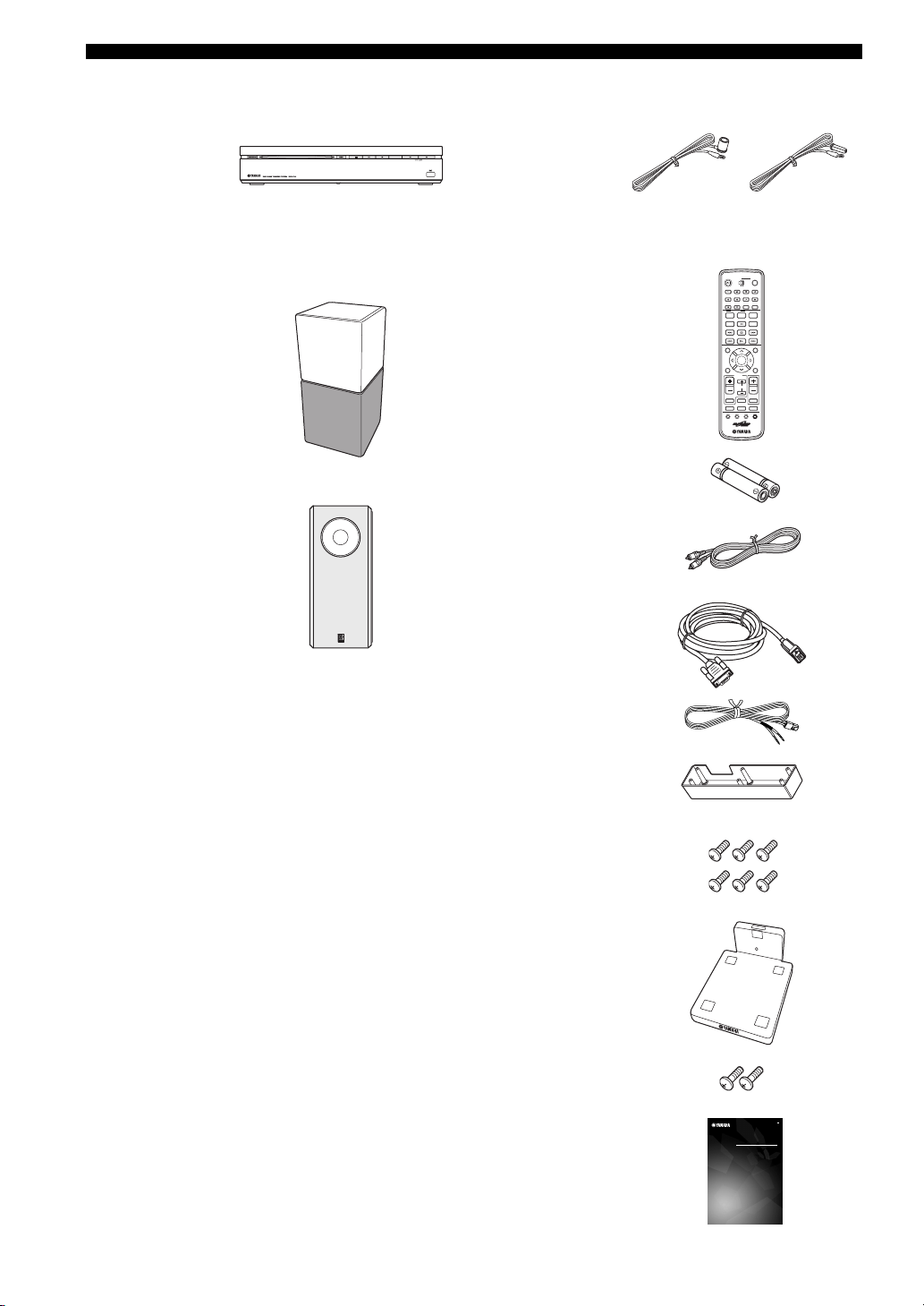
■ Main unit ■ Supplied accessories
Indoor FM antenna
DVD controller
(DVR-700)
(U.S.A., Canada,
Asia and Taiwan
models)
(Europe, Russia
and Australia
models)
Speaker package
Speaker (L/R)
(NS-P700)
Subwoofer/system control
(NS-PSW700)
Remote control
Battery x 2
(AA, R6, UM-3)
Video pin cable (1.5 m)
System control cable (4 m)
Speaker cable x 2 (4 m)
Cover
(For NS-PSW700)
WP87010DVX-700
/
ON
STANDBY
TV STB
FUNC.
10KEY
MUSIC
MOVIE
NIGHT
ENHANCER
STEREO
ZOOM
AUDIO DELAY
DISP. MODE
BLUETOOTH
ON OFF
AUDIO
SUBTITLE
PLAY MODE
LOCK
AUTO/
MANUAL
SRCH MODE
TOP MENU
PRESET/CH
INFO.
A-E/CAT. A-E/CAT.
ENTER
SETUP RETURN
TV
/
STB
CH
TV VOL
TUNER MUTE
TV INPUT
DVD
/
USB INPUT 1-4
POSITION
AREA SOUND TEST
POWER
GAMESPORTS
SLEEP
ON SCREEN
ANGLE
CLEAR
MEMORY
MENU
CODE SET
VOLUME
DOCK
4 En
Screw x 6
(for cover 3 x 6 mm)
Stand x 2
(For NS-P700)
Screw x 2
(for stand 4 x 10 mm)
Owner’s Manual
DVD HOME THEATER SYSTEM
SYSTEME HOME CINEMA AVEC LECTUER DVD
DVX-700
(DVR-700 + NS-PSW700 + NS-P700)
OWNER’S MANUAL
U
MODE D’EMPLOI
Page 9
FUNCTIONAL OVERVIEW
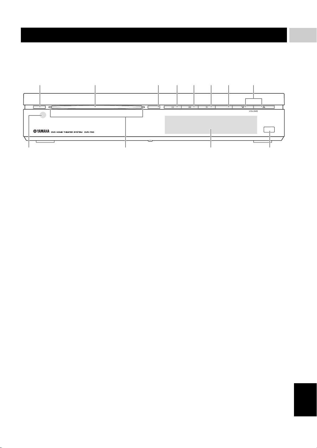
■ Front panel (DVR-700)
12 345678
1
INTRODUCTION
STANDBY / ON
1 STANDBY/ON
Turns on the system, or sets it to standby mode
(Page 22).
2 Disc loading slot
Insert a disc to be played.
3 EJECT
Ejects a disc in the DVD controller.
4 s
Stops playback.
5 e
Pauses playback.
6 h
Starts playback.
EJECT INPUT
USB
B09A
7 INPUT
Selects an input source by pressing repeatedly.
8 VOLUME u / d
Adjusts the volume level.
9 Remote control sensor
Point the remote control towards this sensor.
0 Power indicator
Lights up when system is on.
A Front panel display
Shows information about the operational status of the
unit.
B USB terminal
Connect to the USB connector of your USB device
(Page 35).
5 En
English
Page 10

FUNCTIONAL OVERVIEW
■ Rear panel (DVR-700)
1234
NS-PSW700
SYSTEM
CONNECTOR
P
Y
B
VIDEO
COMPONENT
VIDEO
OUTPUT
PR
HDMI
OUTPUT
1 SYSTEM CONNECTOR terminal
Connect to the subwoofer/system control (Page 16).
2 COMPONENT VIDEO OUTPUT jacks
Connect to the Y PB/CB PR/CR jacks on your TV
(Page 17).
3 VIDEO OUTPUT jack
Connect to the video (composite) jack on your TV
(Page 17).
4 HDMI OUTPUT terminal
Connect to the HDMI input terminal on your TV
(Page 18).
6 En
Page 11
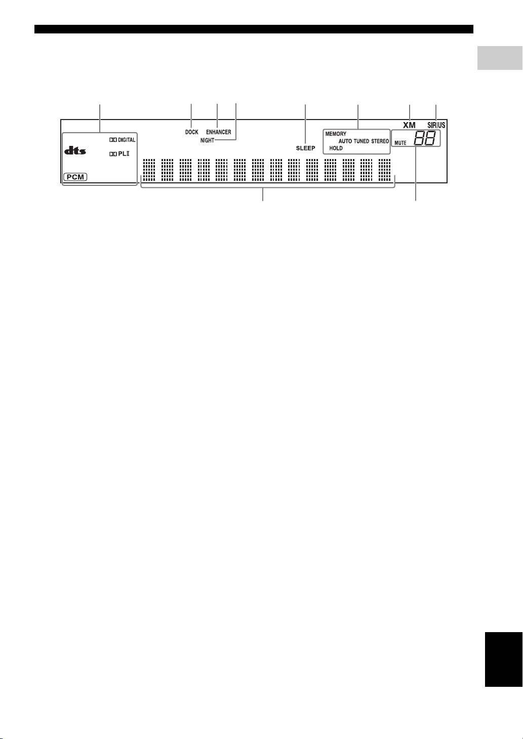
■ Front panel display (DVR-700)
FUNCTIONAL OVERVIEW
1
INTRODUCTION
12345
1 Decoder indicators
The respective indicator lights up when any of the
decoders of the system is functioning.
2 DOCK indicator
– Lights up when the system is receiving a signal
from an iPod stationed in the Yamaha iPod
universal dock (such as YDS-10 or YDS-11, sold
separately) connected to the DOCK terminal of the
subwoofer/system control (Page 20).
– Lights up while the Yamaha Bluetooth wireless
audio receiver (such as YBA-10, sold separately) is
connected to the Bluetooth component (Page 61).
– Flashes while the connected Yamaha Bluetooth
wireless audio receiver (such as YBA-10, sold
separately) and the Bluetooth component are
pairing or while the Yamaha Bluetooth wireless
audio receiver is searching for the Bluetooth
component (Page 61).
3 ENHANCER indicator
Lights up when compressed music enhancer mode is
selected (Page 45).
678
9@
6 Tuner indicators (AUTO/TUNED/STEREO/
MEMORY/HOLD)
AUTO indicator
Lights up when the system is in automatic tuning
mode (Page 46).
TUNED indicator
Lights up when the system is receiving a station
(Page 46).
STEREO indicator
Lights up when the system is receiving a strong signal
from an FM stereo broadcast in automatic tuning
mode (Page 46).
MEMORY indicator
Flashes to show a station can be stored (Page 47).
HOLD Indicator
Flashes while holding the XM/SIRIUS information
(Page 53, 59).
4 NIGHT indicator
Lights up when you select night listening mode
(Page 63).
5 SLEEP indicator
Lights up when sleep mode is on (Page 65).
7 XM indicator
Lights up when the input source is XM Mini-Tuner
(Page 50).
8 SIRIUS indicator
Lights up when the input source is SiriusConnect
tuner (Page 54).
9 Multi information display
Shows the playing time. When you adjust or change a
setting, the value is displayed.
0 MUTE indicator/VOLUME indicator
– Flashes while the mute function is activated.
– Indicates the current volume level.
English
7 En
Page 12
FUNCTIONAL OVERVIEW
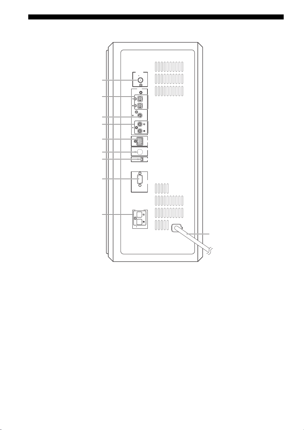
■ Rear panel (NS-PSW700)
1
2
3
4
ANTENNA
75
INPUT
FM
UNBAL
.
OPTICAL
OPTICAL
COAXIAL
ANALOG
5
6
7
8
9
1 ANTENNA terminal
Connect the FM antenna.
2 INPUT 1/2 OPTICAL jacks
Connect to the DIGITAL OUT jack (Optical Type) on
your digital audio component.
These input jacks support PCM, Dolby Digital, and
DTS bitstream.
3 INPUT 3 COAXIAL jack
Connect to the DIGITAL OUT jack (Coaxial Type) on
your digital audio component.
This input jack support PCM, Dolby Digital, and DTS
bitstream.
4 INPUT 4 ANALOG jacks
Connect to the ANALOG OUT jack if the component
does not have DIGITAL OUT jacks.
DVR-700
SPEAKERS
SPEAKER
:
6 MIN.
IMPEDANCE
DOCK
SIRIUS
XM
SYSTEM
CONNECTOR
MAINS
@
5 DOCK terminal
Connect the Yamaha iPod Universal Dock (such as
YDS-10 or YDS-11, sold separately) or Yamaha
Bluetooth wireless audio receiver (such as YBA-10,
sold separately) (Page 20).
6 SIRIUS terminal
Connect to a SiriusConnect tuner (sold separately).
7 XM terminal
Connect to an XM Mini-Tuner and XM Mini-Tuner
Home Dock (sold separately).
8 SYSTEM CONNECTOR terminal
Connect to the DVD controller.
9 SPEAKER terminals
Connect to the speakers.
0 Power cable
Connect to a standard AC outlet.
8 En
Page 13
FUNCTIONAL OVERVIEW
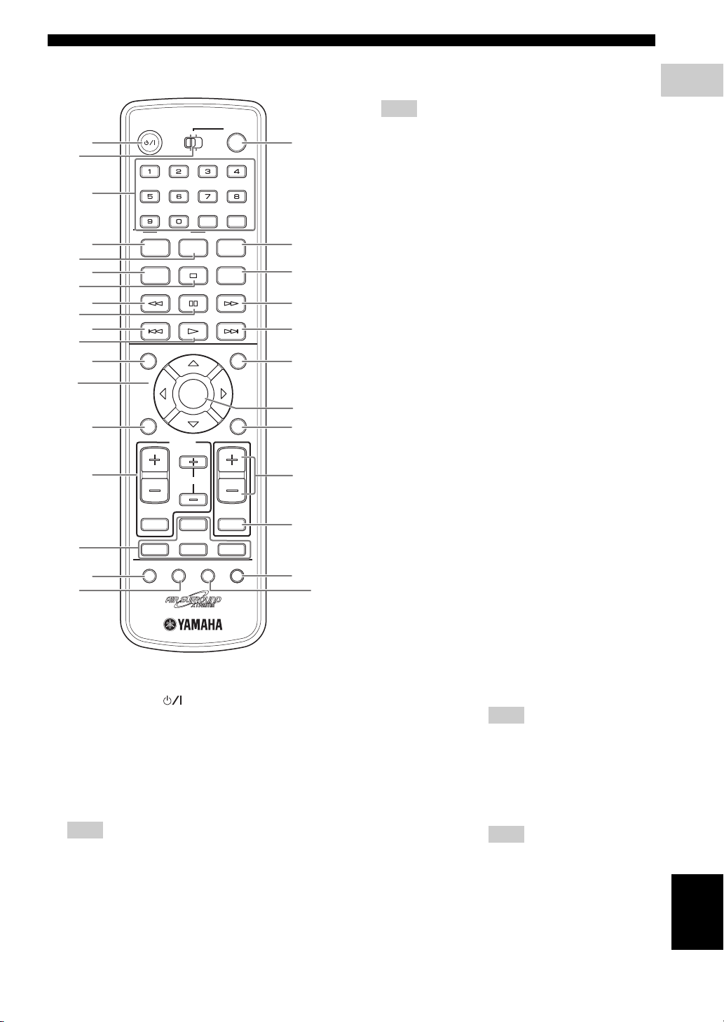
■ Remote control
STANDBY
1
2
4
5
MOVIE
STEREO
DISP. MODE
ON OFF
AUDIO
6
8
9
PLAY MODE
LOCK
A
B
SRCH MODE
D
E
G
I
TOP MENU
INFO.
A-E/CAT. A-E/CAT.
SETUP RETURN
K
M
TV VOL
TV INPUT
P
DVD
POSITION
Q
R
1 STANDBY/ON ( )
Turns on the this system, or sets it to the standby
mode.
2 FUNC./10KEY
Switches the operation of the Function/Numeric
keypad keys. Also, the preset code to operate TV or
STB.
Hint
Using the remote control, you can operate two kinds
of peripheral devices such as TV and satellite tuner.
When operating them, you need to set the preset codes
depending on the components. Refer to “Setting the
preset code” on page 66.
WP87010DVX-700
/
ON
TV STB
FUNC.
10KEY
MUSIC
ENHANCER
AUDIO DELAY
BLUETOOTH
SUBTITLE
AUTO/
MANUAL
PRESET/CH
ENTER
TV
/
STB
CH
TUNER MUTE
/
USB INPUT 1-4
AREA SOUND TEST
NIGHT
ZOOM
POWER
GAMESPORTS
SLEEP
ON SCREEN
ANGLE
CLEAR
MEMORY
MENU
CODE SET
VOLUME
DOCK
3
7
0
C
F
H
J
L
N
O
t
S
3 POWER
Turns on the TV.
Note
To operate your TV with the remote control, you need
to set the preset code. Refer to “Setting the preset
code” on page 66.
4 Function / Numeric keypad 0-9
Operates some functions, such as AIR SURROUND
XTREME, and enters track numbers or other
numbers.
The available operation will be changed depending on
the FUNC./10KEY position.
FUNC./10KEY: FUNC. side
MOVIE
MUSIC
SPORTS
Select surround mode.
GAME
STEREO – Turns extended stereo mode
on and off alternately
(Page 45).
– Turns surround mode off
(Page 43).
ENHANCER Turns compressed music
enhancer mode on and off
alternately (Page 45).
NIGHT Turns night listening mode on
and off alternately (Page 63).
SLEEP Sets the sleep timer (Page 65).
DISP. MODE Changes the brightness of the
front panel display (Page 64).
AUDIO DELAY Delays the output sound to
synchronize it with the video
image (Page 63).
ZOOM Enlarges the pictures while
playing DVD.
Hint
This button can be used
regardless of the FUNC./10KEY
position.
ON SCREEN Displays the disc information on
the TV display.
Hint
This button can be used
regardless of the FUNC./10KEY
position.
FUNC./10KEY: 10KEY side
Enters numeric characters using 0 to 9 buttons.
1
INTRODUCTION
English
9 En
Page 14

FUNCTIONAL OVERVIEW
5 AUDIO
Selects an audio language for the DVD that is playing
(if available).
6 SUBTITLE
Selects a subtitle language for the DVD that is playing
(if available).
7 ANGLE
Selects a camera angle for the DVD that is playing (if
available).
8 PLAY MODE
Displays the Play Mode menu.
9 s
Stops playback.
0 CLEAR
Erases the registered track/chapter order.
A w (LOCK)
Rewinds the disc.
SIRIUS: Sets a parental lock.
B e
Pauses playback.
C f
Fast-forwards the disc.
D b (SRCH MODE)
Selects the previous track or chapter.
XM/SIRIUS: Selects the search mode.
E h (AUTO/MANUAL)
Starts playback.
FM: selects auto/manual tuning (Page 46).
F a (MEMORY)
Selects the next track or chapter.
FM: registers the radio frequency.
G TOP MENU (INFO.)
Displays the top-level disc menu.
iPod: switches operation mode of the iPod.
H MENU
Displays the disc contents menu.
I Cursors ( / / / )
Selects items or changes values in the menu screen.
– Tuning the FM station.
– Controlling an iPod.
– Changing the settings.
J ENTER
Confirms a selection.
K SETUP
Displays the DVD setup menu.
L RETURN (CODE SET)
– Returns to the previous screen when DVD setup
menu is displayed.
– Use to set the preset code. Refer to “Setting the
preset code” on page 66.
M TV/STB control buttons
TV VOL +/–
Adjusts the TV volume level.
CH +/–
Select the TV channel.
TV INPUT
Selects the TV input.
Note
To operate your TV with the remote control, you need
to set the preset code. Refer to “Setting the preset
code” on page 66.
You can select TV or STB by switching FUNC./
10KEY.
N VOLUME +/–
Adjusts the volume level of DVX-700.
O MUTE
Mutes the volume of DVX-700. Press the button again
to mute OFF.
P Input selection buttons
DVD/USB
Switches the input source to DVD or USB. Each time
you press the button, the input source changes in
sequence.
TUNER
Switches the input source to FM/XM/SIRIUS.
INPUT 1-4
Switches the input source to the external input. Each
time you press the button, the input source changes in
sequence from input 1 to input 4.
DOCK
Switches the input source to DOCK.
Selects iPod or Bluetooth as the input source
depending on the option connected to the Dock
terminal.
Q POSITION
Shifts the optimum listening area according to your
listening position (Page 44).
R AREA
Sets the distance between speakers for the best
surround effect (Page 44).
S SOUND
Adjusts the volume balance for the virtual speaker and
subwoofer (Page 64).
T TEST
Outputs the test tone (Page 45).
10 En
Page 15
CONNECTIONS
CONNECTIONS
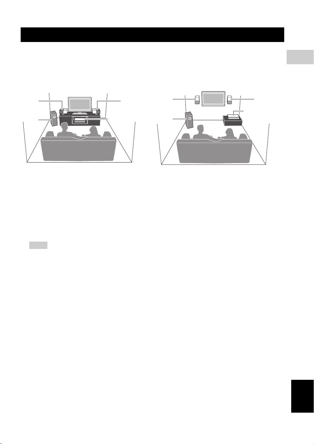
■ Roles and layout of the speakers
To enjoy quality sounds, you need to place the speakers in their appropriate positions and install them correctly.
The following shows the recommended layout of the speakers.
When placing the speakers on a rack When placing the speakers on a wall
11
2
1 Speaker (L, R)
Produces front channel (stereo) sounds. Also produces virtual center channel sounds (dialogue, etc.) and virtual
surround channel sounds effectively using the Yamaha front surround system.
Place the left and right speakers at equal distances away from the listening position so that you can produce high
quality surround sound. You can install the speakers on a rack using the stands or on a wall.
2 Subwoofer/system control
The subwoofer produces bass sounds and LFE sounds contained in Dolby Digital or DTS. Place the subwoofer in the
front of the listening position. Turn it slightly toward the center of the room to reduce wall reflections.
DVD controller
11
DVD controller
2
2
CONNECTIONS
Notes
– To avoid magnetic interference, do not position the speakers too close to your TV.
– Allow adequate ventilation around the DVD controller and subwoofer/system control.
– Bass sounds produced by the subwoofer may be heard differently depending on the listening position and
subwoofer location.
To enjoy desired sounds, try to change the location of the subwoofer according to the listening position.
– You can adjust the surround effect by arranging the position of the speakers (Page 46).
English
11 En
Page 16
CONNECTIONS
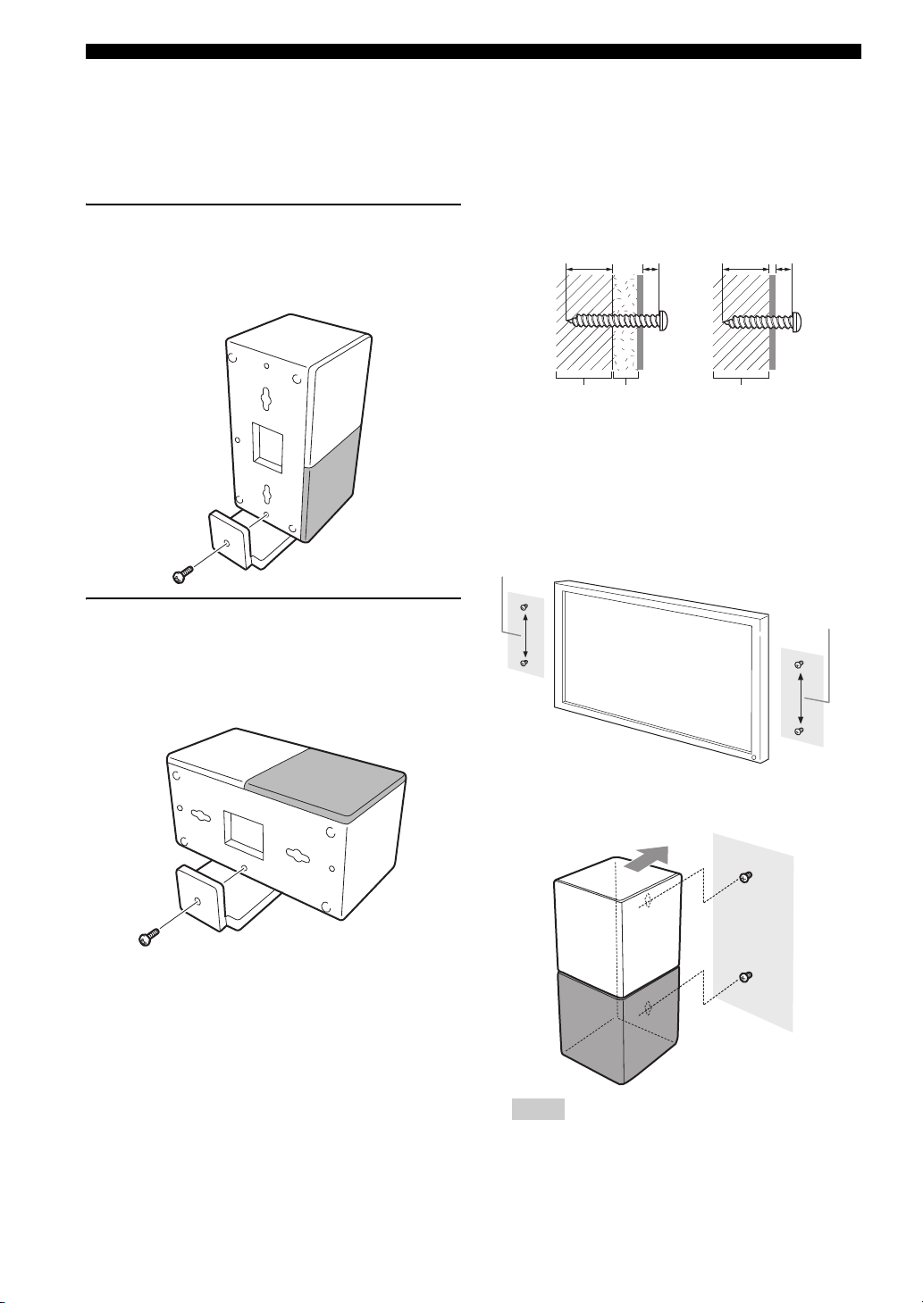
■ Placing the speakers using the stands
You can place the speakers in an upright position or a
horizontal position. Put the speakers on the stands and
secure them with the screws.
When placing the speaker in an
upright position
Place the speaker on the stand vertically, and then secure it
with the screw as shown in the illustration.
■ Placing the speakers on a wall
Put the speakers on a wall using commercially available
screws. Refer to the illustration below for the screw size.
Tapping screw (Available at the hardware store)
Dia.4 mm (1/8")
Installing on a plaster wall.
Min 20 mm
(3/4")
PlasterPillar
or lumber
1 When placing the speakers on a wall, remove the
stands.
2 Install screws on a wall as shown in the illustration.
The distance between the screws: 126 mm for both
sides
126 mm (5")
Installing on a firm wall.
5 mm
(1/4")
Min 20 mm
(3/4")
Pillar
or lumber
5 mm
(1/4")
When placing the speakers in a
horizontal position
Put the speaker on the stand so that the black side of the
speaker becomes outside, and then secure it with the screw
as shown in the illustration.
126 mm (5")
3 Insert the screws into the holes on the back of the
speaker.
Notes
– To attach the speaker to a wall with screws, the
wall must be firm. If not you may cause the speaker
to fall.
12 En
Page 17

– Use commercially available screws that can
support the weight of the installation.
– Make sure you use specified screws to attach the
speakers to a wall. Using clamps other than
specified screws, such as short screws, nails, or
two-sided tape, may cause the speaker to fall.
– After attaching the speakers, check that the
speakers are installed securely. Yamaha will bear
no responsibility for any accidents caused by
improper installations.
CONNECTIONS
2
CONNECTIONS
13 En
English
Page 18
SYSTEM CONNECTIONS
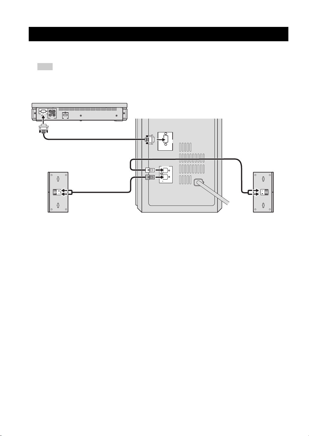
■ Connecting the speakers
Note
Do not connect the power cable of the subwoofer/system control into an AC outlet until all cable connections are
completed.
DVD controller
NS-PSW700
VIDEO
Y
SYSTEM
P
B
PR
CONNECTOR
COMPONENT
VIDEO
HDMI
OUTPUT
OUTPUT
Subwoofer/system control
SYSTEM
CONNECTOR
DVR-700
SPEAKERS
SPEAKER
IMPEDANCE
:
6 MIN.
MAINS
Speaker (R)
Speaker (L)
14 En
Page 19
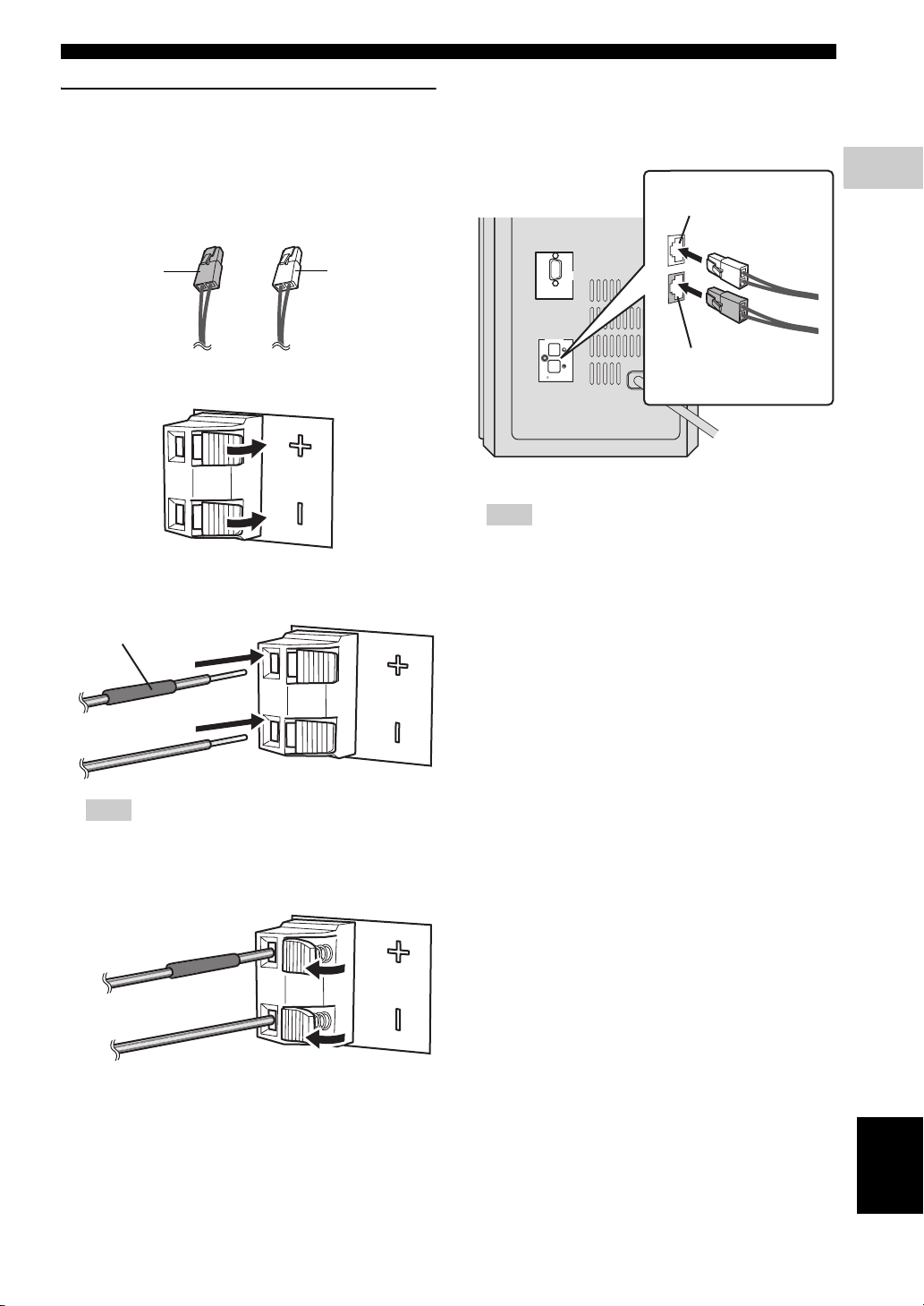
Connecting the speakers and
subwoofer/system control
Connecting the speakers
Confirm the plug colors of the speaker cables.
– Speaker cable with white plug: for speaker (L)
– Speaker cable with red plug: for speaker (R)
SYSTEM CONNECTIONS
Connecting the subwoofer/system control
1 Insert the speaker cable plug until you hear a click
sound.
from speaker (L)
2
CONNECTIONS
for speaker (R):
Red plug
for speaker (L):
White plug
1 Push down the knob of the speaker terminal.
2 Insert the stripped speaker cable into the hole on the
speaker terminal.
Red tube
SYSTEM
CONNECTOR
DVR-700
SPEAKERS
from speaker (R)
SPEAKER
IMPEDANCE
:
6 MIN.
MAINS
Note
Make sure that the cable plugs are connected to the
subwoofer/system control terminals of the same color.
2 Use the same procedure to connect the other speaker
cable.
Note
Connect the cable with red tube to the positive
terminal, and the other cable to the negative terminal.
3 Release the knob of the speaker terminal.
English
15 En
Page 20
SYSTEM CONNECTIONS
E
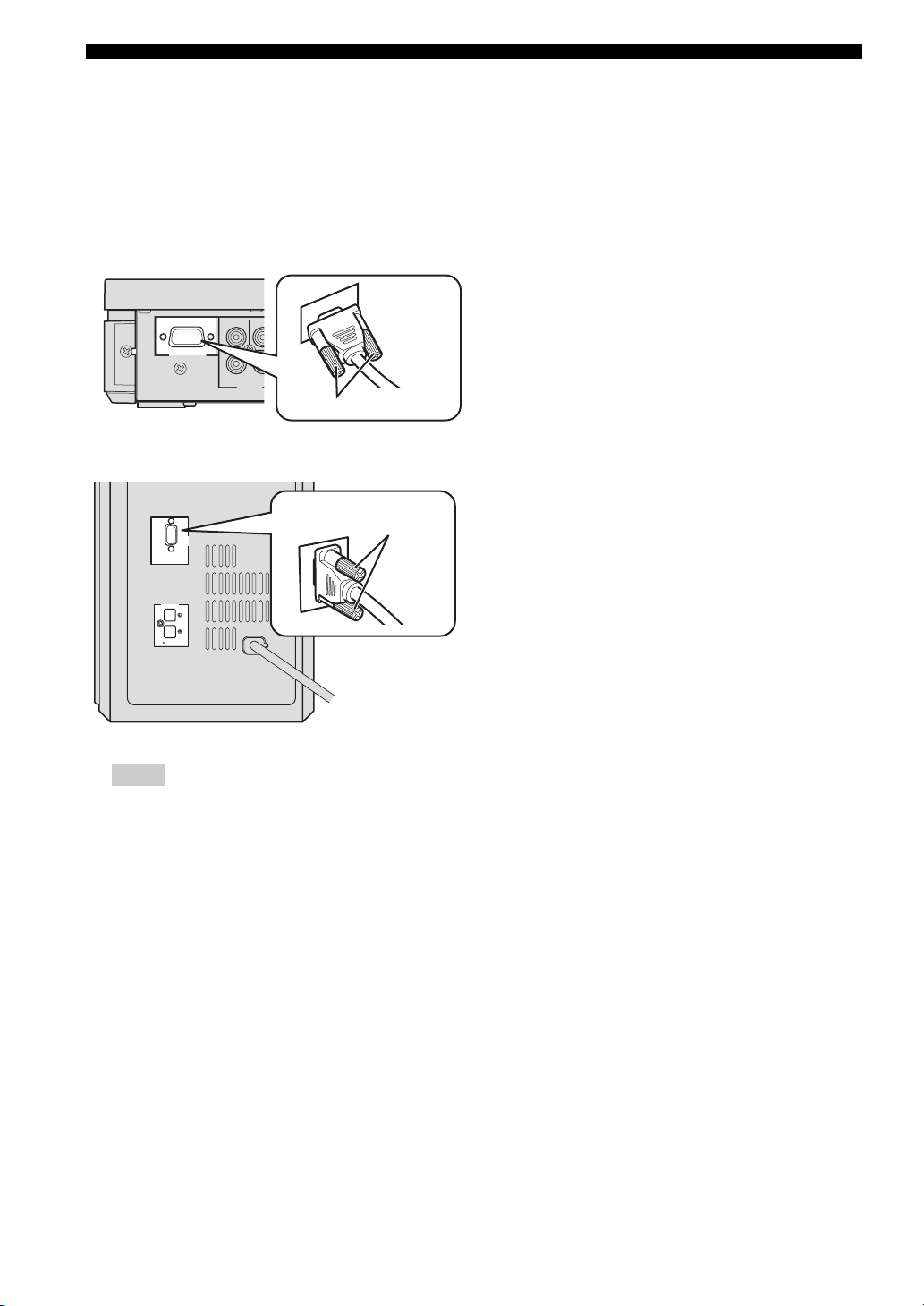
■ Connecting the DVD controller and the subwoofer/system control
Connect the SYSTEM CONNECTOR terminal at the rear
of the subwoofer/system control to the SYSTEM
CONNECTOR terminal at the rear of the DVD controller
using the system control cable.
NS-PSW700
SYSTEM
CONNECTOR
P
Y
B
COMPONENT
VIDEO
OUTPUT
VID
NS-PSW700
Tighten the screws.
Tighten the screws.
DV
MAINS
SYSTEM
CONNECTOR
SPEAKER
:
DVR-700
SPEAKERS
6 MIN.
IMPEDANCE
SYSTEM
CONNECTOR
Notes
– Make sure that the system control cable is correctly
connected. Improper connections may damage the
system due to a short-circuit.
– To prevent unwanted noise, do not place the
subwoofer too close to the DVD controller, AC
power adaptor, TV or other sources of radiation.
– Do not insert the Power cable to an AC outlet until
all connections are completed.
16 En
Page 21
OTHER CONNECTIONS
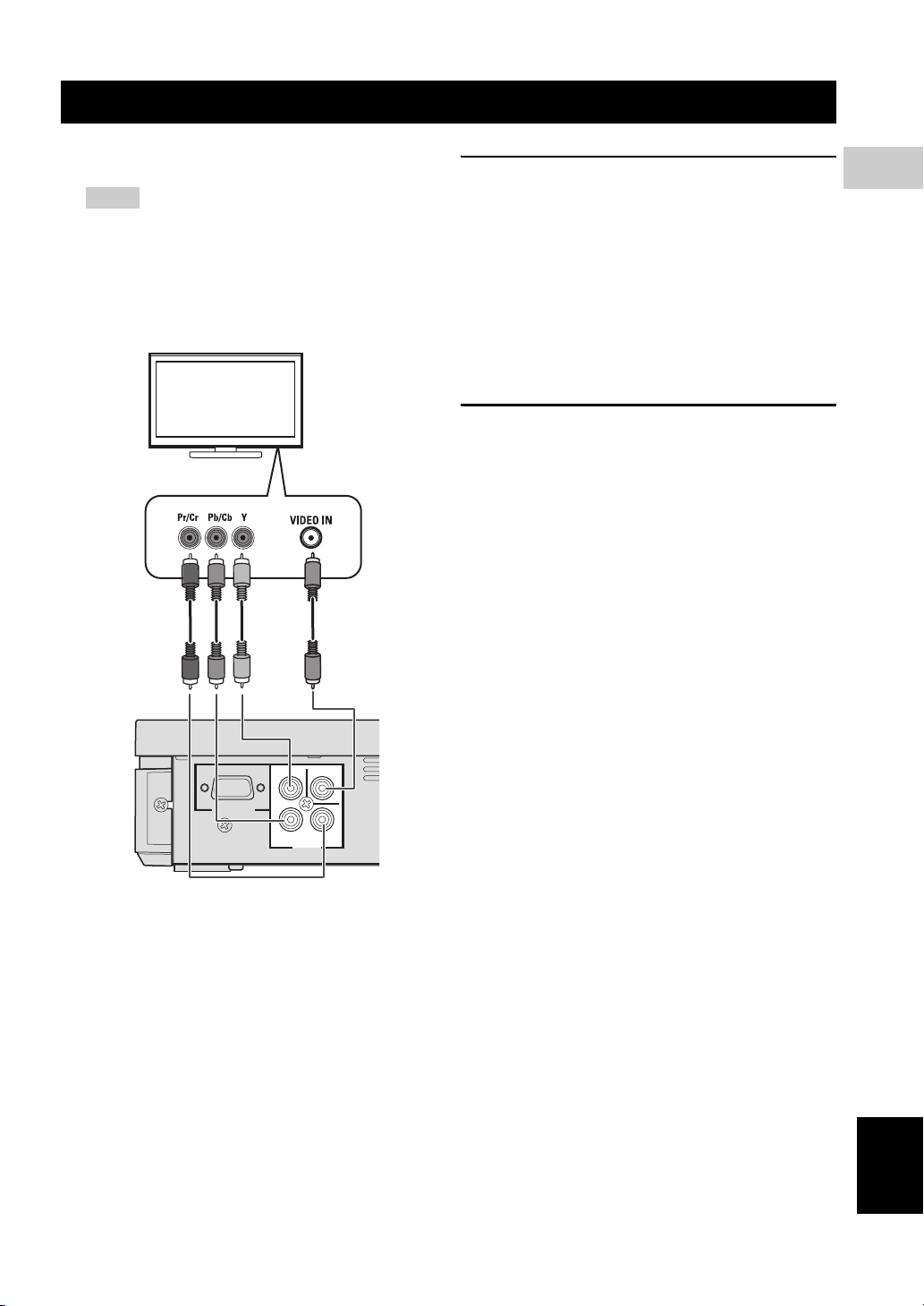
■ Connecting a TV
Notes
– You only need to make one video connection from
the following options (A or B), depending on the
capabilities of your TV.
– Do not connect the power cables until all cable
connections are completed.
TV
<A> <B>
COMPONENT VIDEO OUTPUT jacks
<A>
Use the component video cables (Green/Blue/Red, not
supplied) to connect the DVD controller’s Y P
B PR jacks
to the corresponding component video input jacks (or the
Y PB/CB PR/CR YUV jacks) on your TV.
Progressive scan video quality is only available when
using Y P
B PR in conjunction with a progressive scan TV.
To activate the progressive scan function, refer to
“Selecting the output type for COMPONENT VIDEO
OUTPUT jacks” on page 24.
VIDEO OUTPUT jack <B>
Use the Video pin cable (yellow-supplied) to connect the
DVD controller’s VIDEO OUTPUT jack to the video
input jack (or A/V In/Video In/Composite/Baseband jack)
on your TV.
2
CONNECTIONS
DVD controller
NS-PSW700
SYSTEM
CONNECTOR
P
Y
B
COMPONENT
VIDEO
OUTPUT
VIDEO
PR
English
17 En
Page 22
OTHER CONNECTIONS
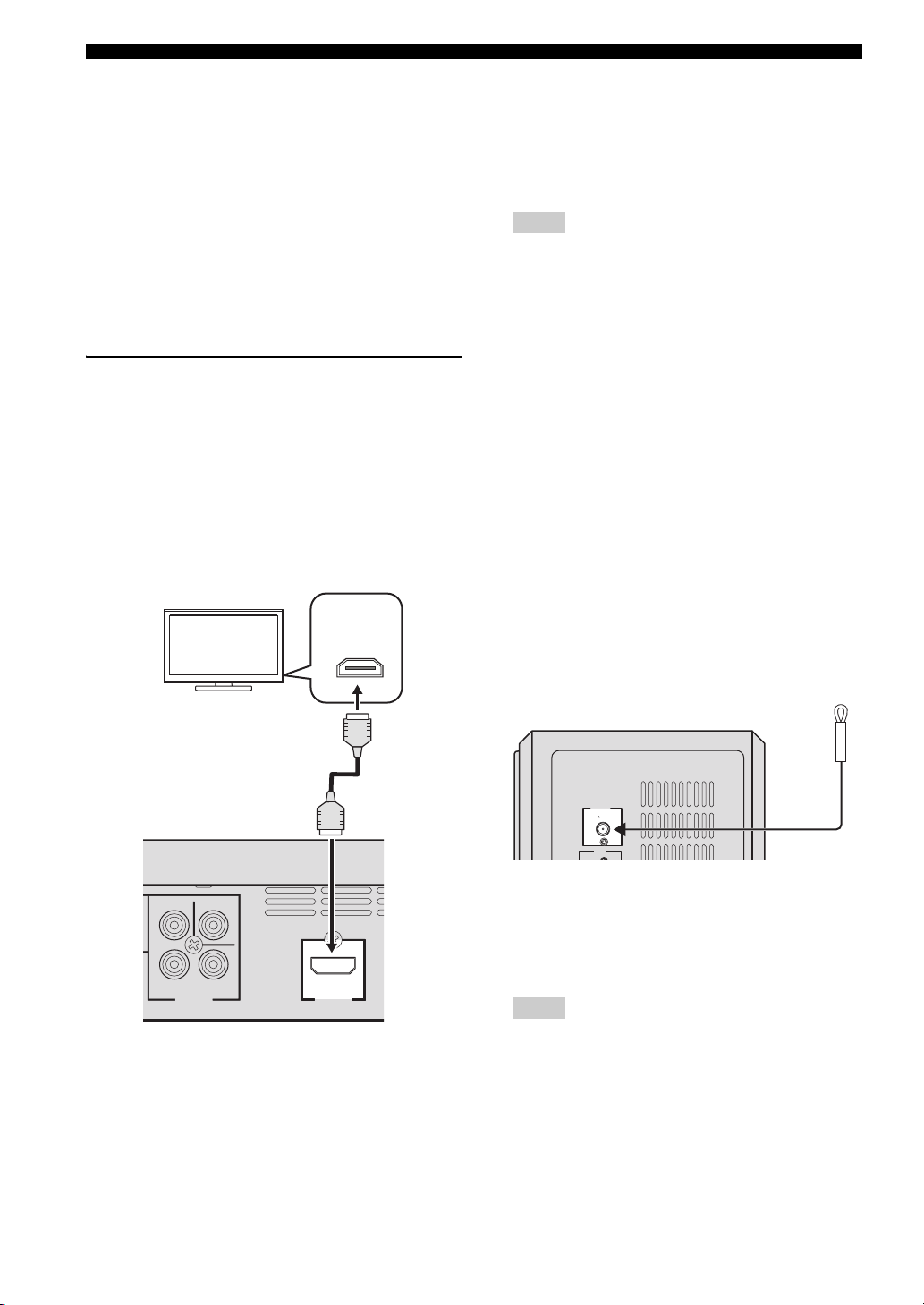
■ Connecting an HDMI component
HDMI (High-Definition Multimedia Interface) is the first
industry-supported, uncompressed, all-digital A/V (audio/
video) interface.
By connecting to an HDMI component (such as a TV),
you can enjoy standard, enhanced or high-definition video
as well as digital audio using a single cable.
When used in combination with HDCP (High-bandwidth
Digital Content Protection), HDMI provides a secure
audio/video interface that meets the security requirements
of content providers and system operators.
For further information on HDMI, visit the HDMI website
at “http://www.hdmi.org/”.
Viewing and Listening to playback
from an HDMI component
To output an HDMI signal, you need to configure the
settings manually. It is necessary to prepare in advance to
output an HDMI signal.
1 Set the system to standby mode.
2 Connect the HDMI terminals on your HDMI
compatible device and the DVD controller using a
commercially available HDMI cable.
TV
HDMI
IN
4 To set the video output according to the HDMI
compatible device, refer to “Video Output” on
page 38 to access the DVD setup menu, and then set
the two items under Video output in the system menu.
– HDMI Resolution
– HDMI Color
Notes
– This unit is designed to connect to HDMI
compatible devices. If you connect to the DVI
component, the system may not operate correctly.
– The DVD controller is not compatible with HDCP-
incompatible HDMI or DVI components.
– You need a commercially available HDMI/DVI
conversion cable when you connect the DVD
controller to other DVI components.
– If you connect the system to the DVI component
with a HDMI/DVI conversion cable, the HDMI
terminal of the DVD controller does not output any
audio signals.
– Do not disconnect or connect the HDMI cable from
the DVD controller or turn off the power of the
HDMI/DVI component connected to the HDMI
OUTPUT terminal of the DVD controller while
data is being transferred. Doing so may disrupt
playback or cause noise.
– PCM signal downmixed to two channels can be
output from the HDMI output terminal.
■ Connecting the FM antenna
DVD controller
VIDEO
Y
B
P
COMPONENT
VIDEO
OUTPUT
P
R
HDMI
OUTPUT
3 To output an audio signal from the DVD controller to
the HDMI compatible device, refer to “System menu”
on page 65.
After doing the settings, set the DVD controller to
standby mode, and then turn on the system again.
18 En
ANTENNA
FM
UNBAL
.
75
INPUT
Subwoofer/system control
Connect an indoor FM antenna to the ANTENNA
terminal. Extend the FM antenna and fix its ends to the
wall.
For better FM stereo reception, connect an external FM
antenna.
Notes
– Adjust the position of the antenna for optimal
reception.
– Position the antenna as far as possible from your
TV, VCR or other sources of radiation to prevent
unwanted interference.
Page 23
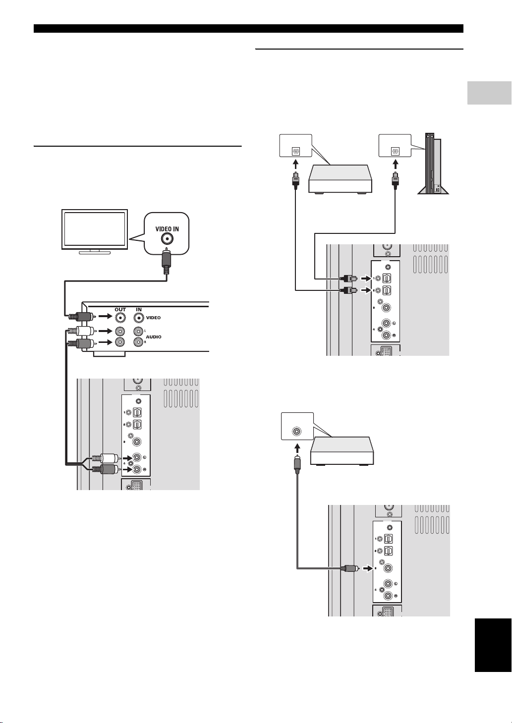
■ Connecting external AV components
If you connect external AV equipment, such as a VCR or
cassette deck, to the audio input terminal on the
subwoofer/system control, you can listen to those audio
sources on the system.
This section provides some examples of VCR and digital
AV equipment connections.
Connecting analog AV components
Connect the DVD controller and external AV equipment
as shown in the illustration.
OTHER CONNECTIONS
Connecting digital AV components
Connect the subwoofer/system control and external AV
equipment as shown in the illustration.
When connecting to optical type digital AV
components
OPTICAL
DIGITAL OUTPUT
OPTICAL
DIGITAL OUTPUT
2
CONNECTIONS
TV
Subwoofer/system control
INPUT
VCR (for example)
OPTICAL
OPTICAL
COAXIAL
ANALOG
DOCK
Digital audio
component
INPUT
OPTICAL
OPTICAL
COAXIAL
ANALOG
Game
console
DOCK
Subwoofer/system control
When connecting to coaxial type digital
AV components
COAXIAL
DIGITAL OUTPUT
Digital audio
component
INPUT
OPTICAL
OPTICAL
COAXIAL
ANALOG
DOCK
English
19 En
Page 24
OTHER CONNECTIONS
OPTICAL
OPTICAL
Y
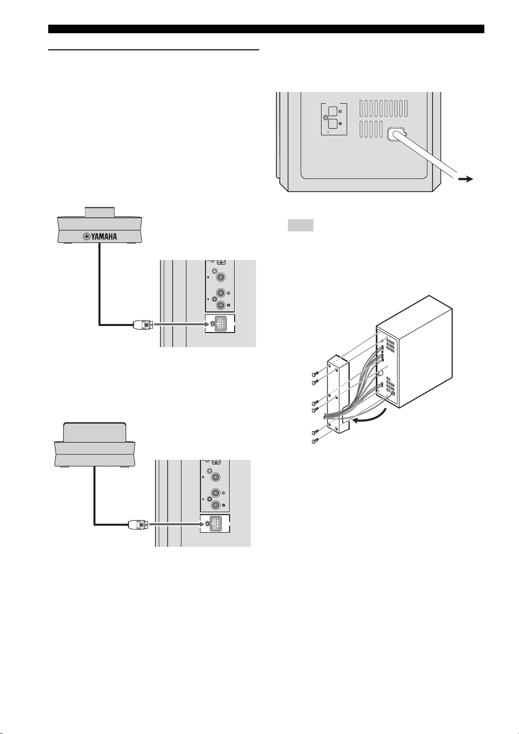
Connecting optional equipment
The system is equipped with the DOCK terminal, which
allows you to connect the Yamaha iPod universal dock
(such as YDS-10 or YDS-11, sold separately) or Yamaha
Bluetooth wireless audio receiver (such as YBA-10, sold
separately). Connect the optional equipment to the DOCK
terminal of the subwoofer/system control using its
dedicated cable.
When connecting the Yamaha iPod
universal dock
Yamaha iPod universal dock
(such as YDS-10 or YDS-11, sold separately)
COAXIAL
ANALOG
■ Connecting the power cable
After you have made all connections, connect the power
cable of the subwoofer/system control.
SPEAKERS
SPEAKER
IMPEDANCE
:
6 MIN.
Hint
You can attach or detach the cover according to your
preference after you have made all connections.
Attach the cover to the rear panel of subwoofer/system
control using the 6 supplied screws as shown.
MAINS
To AC
outlet
DOCK
When connecting the Yamaha Bluetooth
wireless audio receiver
amaha Bluetooth wireless audio receiver
(such as YBA-10, sold separately)
COAXIAL
ANALOG
DOCK
20 En
Page 25
PREPARATION
GETTING STARTED
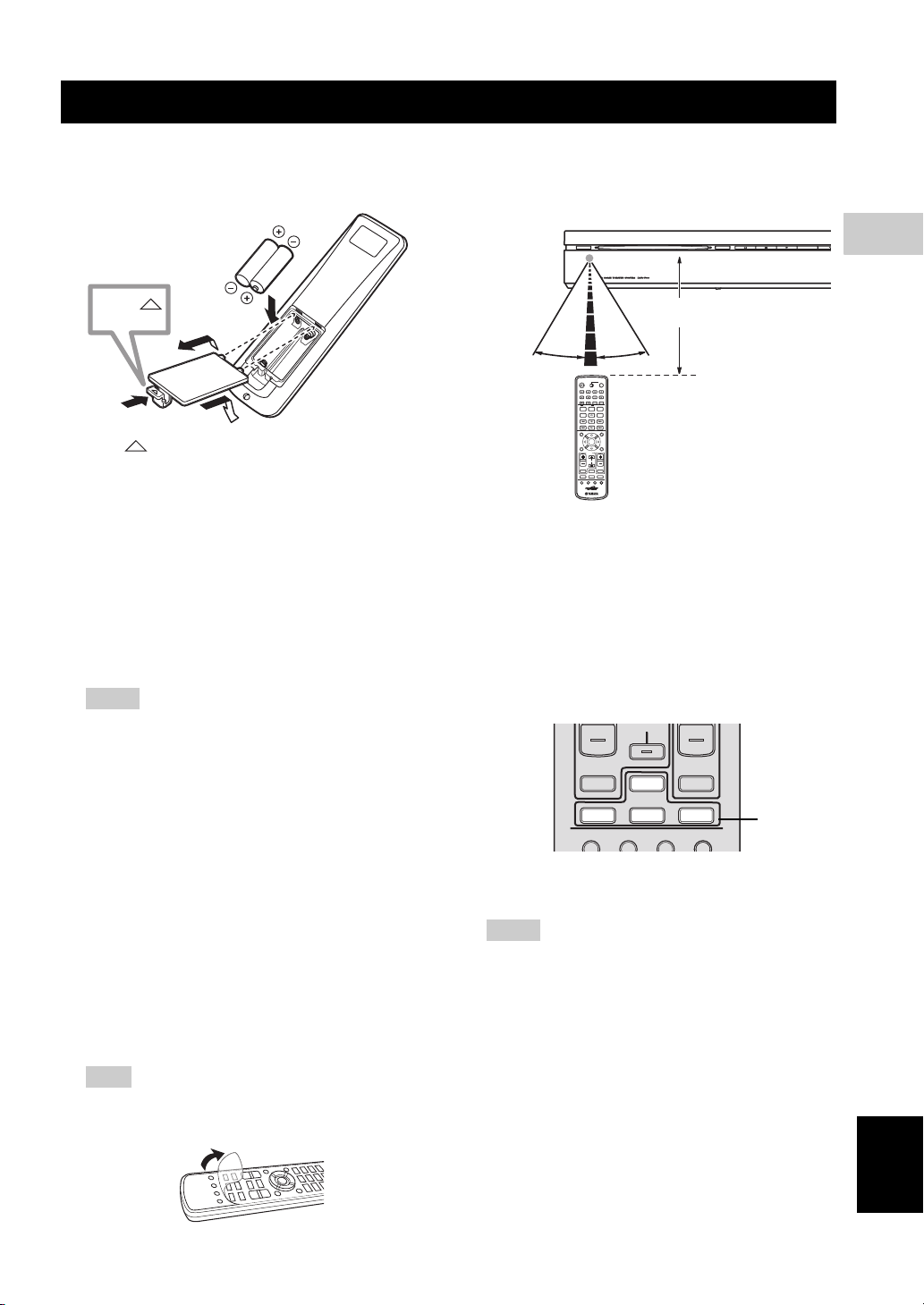
■ Inserting batteries into the remote control
Press
1
1 Press on the battery cover and open the cover.
2 Insert the two supplied batteries (AA, R6, UM-3) into
the battery compartment.
Insert the batteries according to the polarity markings
(+ and –).
3 Close the battery cover.
Replacing the batteries
If the batteries run low, the effective operation distance of the
remote control decreases considerably. If this happens,
replace the batteries with two new ones as soon as possible.
Notes
– Do not use an old battery together with new one.
– Do not use different types of batteries (for
example, alkaline and manganese) together. Each
type of battery has its own characteristics even if
they are similar in shape.
– If the batteries run out, immediately remove them
from the remote control to prevent an explosion or
acid leak.
– Dispose of the batteries according to the regional
regulations.
– If a battery starts leaking, dispose of it
immediately.
Be careful not to let leaking battery acid come into
contact with your skin or clothing. Before inserting
new batteries, wipe the compartment clean.
– Replace the batteries within two minutes to
preserve the preset code in the remote control.
Hint
Remove the transparent sheet before using the remote
control.
2
3
■ Using the remote control
Use the remote control within 6 m of the DVD controller
and point it toward the remote control sensor.
STANDBY / ON
30˚ 30˚
ENTER
/
STB
TV
CH
Within 6 m
EJECT
Basic operation of the remote control
1 Use the Input selection buttons on the remote control
to select the input source you wish to control (for
example DVD/USB).
→ The selected source appears in the front panel
display.
When the button contains several input sources such
as DVD/USB and INPUT 1-4 buttons, the input
source switches each time you press the button.
CH
TV VOL
TV INPUT
/
USB INPUT 1-4
DVD
POSITION
AREA SOUND TEST
2 Operate the desired function (for example, h or b
/ a).
Notes
– Be careful not to spill liquid on the remote control.
– Be careful not to drop the remote control.
– Do not leave the remote control in the following
places:
– hot or humid places, such as near a heater or in a
bathroom
– extremely cold places
– dusty places
– To operate your TV with the remote control, you
need to set the preset code.
Refer to “Setting the preset code” on page 66 for
how to change the preset code.
VOLUME
TUNER MUTE
DOCK
Input
selection
buttons
3
PREPARATION
English
21 En
Page 26

GETTING STARTED
■ Turn on the system
Press STANDBY/ON on the DVD controller or the
remote control.
The LED indicators beside the disc loading slot light up
when the system is turned on.
STANDBY/ON
STANDBY / ON
STANDBY
MOVIE
STEREO
Light up
/
ON
FUNC.
MUSIC
ENHANCER
WP87010DVX-700
TV STB
10KEY
NIGHT
POWER
GAMESPORTS
SLEEP
EJECT
22 En
Page 27

■ Setting the video input/output
Notes
– Make sure that you have completed all the
necessary connections (Refer to “Connecting a
TV” on page 17).
– If the settings you have selected are not
appropriate, you can reset DVD settings to the
initial factory settings (Refer to “System menu” on
page 65).
1 Press DVD/USB repeatedly until “DVD” appears in
the front panel display.
2 Turn on the TV and set to the correct video-in
channel.
→ You should see the background screen on the TV.
– Usually this channel is between the lowest and
highest channels and may be called FRONT, A/V
IN or VIDEO. See your TV manual for more
details.
– Or, you may go to channel 1 on your TV, then
press the Channel down button repeatedly until you
see the Video In channel.
– Or, the TV remote control may have a button or
switch that chooses different video modes.
GETTING STARTED
Setting the TV display
Set the aspect ratio of the DVD controller according to the
TV you have connected. The format you select must be
available on the disc. If it is not, the TV display setting
will not affect the picture during playback.
TOP MENU
PRESET/CH
INFO.
A-E/CAT. A-E/CAT.
SETUP RETURN
ENTER
TV
/
STB
1 Press SETUP on the remote control.
DVD setup menu is displayed on the screen.
Play Mode
Initial Setting
MENU
CODE SET
CH
Video Adjust
Disc Navigator
3
PREPARATION
2 Press / / / on the remote control to
highlight [Initial Settings], and then press ENTER.
Initial Setting
Video Output
Language
Display
Options
TV Screen 4:3 (Letter Box)
Component Out Interlace
HDMI Resolution
HDMI Color Component
720x480p
3 Press / on the remote control to highlight
[Video Output], and then press ENTER.
English
23 En
Page 28

GETTING STARTED
4 Press / on the remote control to highlight
[TV Screen], and then press ENTER.
Initial Setting
Video Output
Language
Display
Options
TV Screen 4:3 (Letter Box)
Component Out Interlace
HDMI Resolution
HDMI Color Component
720x480p
Selecting the output type for
COMPONENT VIDEO OUTPUT jacks
To use progressive display function, connect to a TV,
which has that function, via COMPONENT VIDEO
OUTPUT jacks.
1 Press SETUP on the remote control.
2 Press / / / on the remote control to
highlight [Initial Settings], and then press ENTER.
3 Press / on the remote control to highlight
[Video Output], and then press ENTER.
5 Press / on the remote control to highlight one
of the options below, and then press ENTER.
4:3 (Letter Box)
Select this if you have a conventional TV. In this case, a
wide picture with black bar on the upper and lower
portions of the TV screen will be displayed.
4:3 (Pan&Scan)
Select this if you have a conventional TV and want both
sides of the picture to be trimmed or formatted to fit your
TV screen.
Note
If the disc does not support an aspect ratio of 4:3
(Pan&Scan), the content is displayed in 4:3 (Letter
Box).
16:9 (Wide)
Select this if you have a wide-screen TV.
16:9 (Compressed)
Select this if a wide-screen TV is connected to the DVD
controller with an HDMI cable, and set HDMI Resolution
to either [1920 x 1080p], [1920 x 1080i], or [1280 x
720p]. When playing back a content whose aspect ratio is
4:3, black bars cover the sides of the screen.
4 Press / on the remote control to highlight
[Component Out], and then press ENTER.
Initial Setting
Video Output
Language
Display
Options
TV Screen 4:3 (Letter Box)
Component Out Interlace
HDMI Resolution
HDMI Color Component
720x480p
5 Press / on the remote control to highlight
[Progressive] / [Interlace], and then press ENTER.
6 When the confirmation screen appears, press ENTER
again.
To cancel the setting, press RETURN.
Note
Do not select [Progressive] if your TV does not have a
progressive display function.
If your TV is also connected via HDMI OUTPUT
terminal, the system may ignore this setting and
output the progressive signal from COMPONENT
VIDEO OUTPUT jacks.
24 En
Page 29

■ Setting language preferences
You can select your preferred language settings so that
this controller will automatically switch to your preferred
language whenever you load a disc. If the language
selected is not available on the disc, the disc’s default
setting language will be used instead. The OSD (on-screen
display) language for the DVD setup menu will remain as
you set it, regardless of various disc languages.
On-screen display (OSD) language
1 Press SETUP on the remote control.
DVD setup menu appears on the screen.
2 Press / / / on the remote control to
highlight [Initial Settings], and then press ENTER.
3 Press / on the remote control to highlight
[Display], and then press ENTER.
Initial Setting
GETTING STARTED
Audio, Subtitle and Disc menu
languages
1 Press SETUP on the remote control.
DVD setup menu appears on the screen.
2 Press / / / on the remote control to
highlight [Initial Settings], and then press ENTER.
3 Press / on the remote control to highlight
[Language], and then press ENTER.
Initial Setting
Video Output
Language
Display
Options
Audio Language English
Subtitle Language English
DVD Menu Lang. English
Subtitle Display On
3
PREPARATION
Video Output
Language
Display
Options
OSD Language English
Angle Indicator
On
4 Press / on the remote control to highlight
[OSD Language], and then press ENTER.
5 Press / on the remote control to select a
language, and then press ENTER.
4 Press / on the remote control to highlight the
item below, and then press ENTER.
– Audio Language
– Subtitle Language
– DVD Menu Language
Hint
Refer to page 40 for the other items.
5 Press / on the remote control to select a
language, and then press ENTER.
25 En
English
Page 30

BASIC OPERATIONS
DISC OPERATION
This unit is designed for use with DVD, CD, Video CD,
and Super Video CD, as well as DivX® files and WMV
files recorded on CD-R or DVD-R/DVD+R.
IMPORTANT!
– DVD discs and players are designed with regional
restrictions. Before playing a disc, make sure that
the disc is for the same zone as your DVD
controller.
– Do not insert any objects other than discs into the
disc loading slot. Doing so may cause the DVD
controller to malfunction.
– Depending on the disc, some functions may be
prohibited.
– This unit is not compatible with 8-cm discs.
■ Playing discs
1 Turn on the system.
2 Press DVD/USB repeatedly until “DVD” appears in
the front panel display.
3 Turn on the TV power and set to the correct Video-in
channel (Refer to “Setting the video input/output” on
page 23).
→ You should see the background screen on the TV.
4 Insert the disc into the disc loading slot.
STANDBY / ON
5 Press h to start playback.
→ If a disc menu appears on the TV, refer to “Using
the disc menu (DVD only)” on page 28.
→ If the disc is locked by parental lock function, you
must enter your 4-digit password (Refer to “Parental
Lock” on page 41).
Note
If you do the operation that is not available during
playback, a message “This operation can’t be
performed.” or “Depending on the disc, this operation
may be prohibited.” appears.
EJECT
Playing DivX® video/WMV files
DivX® video file
This unit can play DivX
DVD-R/-RW, DVD+R/+RW discs. By default they will
be played in alphabetical order. The supported files are
shown below.
– Plays all versions of DivX
®
6) with enhanced playback of DivX®
DivX
media files and the DivX
– The following filename extensions are supported
“.avi” and “.divx”.
Displaying external subtitle files
The font sets listed below are available for external
subtitle files. You can see the proper font set on-screen
by setting [Subtitle Language] to match the subtitle
file.
Group 1
Group 2
Group 3
Group 4
Group 5
– Some external subtitle files may be displayed
incorrectly or not at all.
– For external subtitle files, the following subtitle
format filename extensions are supported:
“.srt”, “.sub”, “.ssa”, “.smi”
– The filename of the movie file has to be
repeated at the beginning of the filename for the
external subtitle file.
– The number of external subtitle files which can
be switched for the same movie file is limited to
a maximum of 10.
®
videos recorded on CD-R/RW,
®
video (including
®
media format.
Albanian (sq), Basque (eu), Catalan (ca),
Danish (da), Dutch (nl), English (en),
Faroese (fo), Finnish (fi), French (fr),
German (de), Icelandic (is), Irish (ga),
Italian (it), Norweigian (no),
Portuguese (pt), Rhaeto-Romanic (rm),
Scottish (gd), Spanish (es), Swedish (sv)
Albanian (sq), Croatian (hr), Czech (cs),
Hungarian (hu), Polish (pl),
Romanian (ro), Slovak (sk),
Slovenian (sl)
Bulgarian (bg), Byelorussian (be),
Macedonian (mk), Russian (ru),
Serbian (sr), Ukrainian (uk)
Hebrew (iw), Yiddish (ji)
Turkish (tr)
26 En
Page 31

DISC OPERATION
WMV file
WMV content can be encoded by using Windows Media
Encoder.
The supported files are shown below.
– The DVD controller is compatible with WMV9
files that are encoded by using the Windows Media
Encoder 9 Series, with “.wmv” as an filename
extension.
– Compatible with size under 720 x 576 pixels/720 x
480 pixels.
– The available maximum bit rate is about 2 to
3 Mbps. The maximum bit rate varies depending
on the encode method.
– Advanced Profile is not supported.
– DRM-Protected video files are not played in the
DVD controller.
■ Basic playback controls
BLUETOOTH
LOCK
/
ON
TV STB
FUNC.
MUSIC
ENHANCER
AUDIO DELAY
SUBTITLE
AUTO/
PRESET/CH
WP87010DVX-700
10KEY
NIGHT
ZOOM
MANUAL
POWER
GAMESPORTS
SLEEP
ON SCREEN
ANGLE
CLEAR
MEMORY
MENU
When using Numeric
keypad 0-9
Switch FUNC./10KEY to
10KEY
Numeric keypad 0-9
STANDBY
MOVIE
STEREO
DISP. MODE
ON OFF
AUDIO
PLAY MODE
SRCH MODE
TOP MENU
To pause playback
During playback, press e.
– To resume normal playback, press h.
To stop playback
Press s.
To select track/chapter
Press b / a to select previous/next track or chapter.
You can enter a track/chapter number using Numeric
keypad 0-9.
To search backward/forward
Press w / f.
– To resume normal playback, press h.
– When searching, press w / f again to increase the
search speed. (DVD, CD, and VideoCD only)
To playback in slow motion
During pause, press and hold f to play back in slow
motion. To resume normal playback, press h.
During pause, press and hold w to play back in reverse
slow motion. (DVD only)
4
BASIC OPERATIONS
Hint
During slow motion playback, press w / f to
change the playback speed. (DVD, CD, and Video CD
only)
To advance by frame
During pause, press f to advance by frame. To resume
normal mode, press h.
During pause, press w to reverse by frame. (DVD
only)
To adjust the volume level
Press VOLUME +/– on the remote control or VOLUME
u / d on the DVD controller. The volume level appears
in the front panel display.
27 En
English
Page 32

DISC OPERATION
■ Ejecting a disc
Press s to stop disc playback, and then press EJECT on
the DVD controller.
EJECT
STANDBY / ON
Note
Do not push the ejected disc when reloading it. To
reload the ejected disc, press EJECT, or remove the
disc from the disc loading slot fully, then insert it to
the disc loading slot once again.
EJECT
■ Using the disc menu (DVD only)
To display the disc menu
Press TOP MENU to display the top-level disc menu.
Press MENU to return to the main menu. The same menu
as the top-level disc menu may appear depending on the
disc.
Hint
– Depending on the disc, a menu may appear on the
TV screen once you load a disc.
– The disc menu is displayed when you press TOP
MENU during playing DivX
Note
Depending on the disc, these menus do not appear on
the TV screen.
To select a playback feature or item
Press / / / on the remote control, then press
ENTER to start playback.
You can also specify the number to select a feature or
item.
To enter a number, switch FUNC./10KEY to 10KEY.
®
files. (If available)
■ Playback control (PBC) (Video CD only)
Some Video CD/super Video CD discs are compatibility
with PBC function.
PBC playback allows you to play Video CDs
interactively, following the menu on the display.
To display the PBC menu
When you insert a video CD or super video CD with PBC
function and press h, playback starts with the function.
During playback, press RETURN to display the menu.
Press b / a to display the other menu on the
previous/next page.
To select a track in PBC menu
To select a track, switch FUNC./10KEY to 10KEY, enter
the number, and then press ENTER.
Note
To disable PBC, press s twice, then press a. You
can enter a track number using Numeric keypad 0-
9 instead of pressing a.
To enable PBC again, press s twice, then press h to
play back.
■ Changing soundtrack language
While playing a DVD with multiple language
soundtracks, press AUDIO repeatedly to select the
language.
Notes
– If you cancel the resume mode or eject the disc, the
language gets back to the default setting.
– When playing a Video CD, it switches 1/L (Left)
and 2/R (Right).
– You can change the soundtrack language by
pressing AUDIO during playing DivX
files. (if available)
– Depending on the disc, you can change the
soundtrack language only in the disc menu.
®
video
28 En
Page 33

DISC OPERATION
■ Changing subtitle language
This operation works only on DVDs with multiple subtitle
languages. You can change the language you want while
playing a DVD.
Press SUBTITLE repeatedly to select a language from the
various subtitle languages.
Notes
– If you cancel the resume mode or eject the disc, the
language gets back to the default setting.
– Depending on the disc, you can change the
language only in the disc menu.
– You can change the subtitle language by pressing
SUBTITLE during playing DivX
available)
®
video files. (if
■ Resuming playback from the last stopped point
With the exception of VR format DVD-R/-RW discs,
when you stop playback of a DVD, CD, or Video CD/
Super video CD or DivX
“RESUME” appears in the front panel display indicating
that you can resume playback again from that point.
With DVDs and Video CD/Super video CDs, if you eject
the disc in the DVD controller after stopping playback, the
last play position is stored in memory. If the next disc you
load is the same one, “Last Memory” appears and
playback will resume. For DVD-Video discs, the system
stores the play position of the last five discs. When one of
these discs is next loaded, you can resume playback.
®
video/WMV discs,
■ Displaying disc information
Press ON SCREEN to display track, chapter and title
information. Press ON SCREEN repeatedly to select the
information.
■ Zooming in
This function allows you to enlarge the picture double or
quadruple of the original size. While playing a disc, press
ZOOM once to double or twice to quadruple the size. You
can move the zoom point using / / / .
Press ZOOM one more time to return to the original size.
4
BASIC OPERATIONS
Hints
– To clear the resume point, press s again while
“RESUME” is displayed.
– If you don’t need the Last Memory function when
you stop a disc, you can press EJECT to stop
playback and eject the disc.
Notes
– Resume and Last Memory functions may not work
with some discs.
– As for CD and movie files (DivX
resume point is cleared when the disc is ejected or
the input is changed.
®
/WMV), the
■ Viewing from another angle
If the disc contains sequences recorded from different
camera angles, the angle mark appears on the screen.
Press ANGLE repeatedly to select the desired angle.
Hint
You can hide the angle mark (Page 41).
English
29 En
Page 34

DISC OPERATION
■ Advanced operation
When playing discs, you can use advanced operations
such as repeat playback and programming playback. Use
the menu to set them.
PLAY MODE
LOCK
AUTO/
SRCH MODE
TOP MENU
PRESET/CH
INFO.
A-E/CAT. A-E/CAT.
SETUP RETURN
MANUAL
ENTER
CLEAR
MEMORY
MENU
A-B repeat playback
Select [A-B Repeat] in the Play Mode menu, then press
ENTER.
Specify the section according to the following procedure.
Once you specify the section, repeat playback starts.
Starting point:
End point:
Exiting repeat playback:
Select [A (Start)], then press
ENTER at the point you want
to start repeating.
Select [B (End point)], then
press ENTER at the point you
want to end repeating.
Select [OFF], then press
ENTER.
1 Press PLAY MODE on the remote control.
Play Mode menu appears.
Play Mode
A-B Repeat
Repeat
Random
Program
Serch Mode
A (Start Point)
B (End Point)
Off
2 Use / to select playback function, then press
ENTER.
Setup for each items. Refer to the description below.
[A-B Repeat]
Repeats a specific section between A
and B
[Repeat]
[Random]
[Program]
Repeats title/chapter/disc/track
Plays titles/chapters/tracks randomly
Plays titles/chapters/tracks in the
order you want
[Search Mode]
Plays a specific chapter/track/time
that you want to play
3 Press SETUP to return to the previous screen.
Notes
– A-B repeat playback is not available for DivX®
Video/WMV discs.
– You cannot specify the section that straddles
tracks.
Repeat playback
Select [Repeat] in Play Mode menu, then press ENTER.
Select [Title Repeat]/[Chapter Repeat], then press
ENTER at the point you want to repeat. Repeat playback
starts.
To exit the repeat playback, select [Repeat Off], then press
ENTER.
Available repeat playback
DVD:
CD/Video CD:
DivX®/WMV:
[Title Repeat], [Chapter Repeat]
[Disc Repeat], [Track Repeat]
[Title Repeat], [Chapter Repeat]
(if supported)
Hint
You can use program playback with repeat playback.
If program playback is active, you can select [Program
Repeat].
Random playback
Select [Random] in Play Mode menu, then press ENTER.
When playing DVD, select [Random Title]/[Random
Chapter], then press ENTER.
When playing CD/Video CD, select [On], then press
ENTER.
To exit the random playback, select [Random Off], then
press ENTER.
30 En
Page 35

Program playback
Select [Program] in the Play Mode menu, then press
ENTER.
When playing a DVD, you can program the order the
titles/chapters are played back. When playing a CD/Video
CD, you can only program the order the tracks are played
back.
Programming the playback order
Select [Create/Edit] and press ENTER to open program
list to set the playback order. Use / / / and
ENTER to program the order. You can store up to 24
steps.
Each time you press ENTER, the step moves to the next.
Use the same procedure to complete the programming.
Program
Program Step
01.
02.
03.
04.
05.
06.
07.
08.
Track 1-14
Track 01
Track 02
Track 03
Track 04
Track 05
Track 06
Track 07
Track 08
Total Time 000.00
DISC OPERATION
Search mode types
DVD:
[Title Search], [Chapter Search], [Time
Search]
CD/Video CD:
DivX®/WMV:
[Track Search], [Time Search]
[Time Search], [Chapter Search]
(if supported)
You can select [Time Search] during playback. Enter a 4digit number to specify the minutes and seconds. For
example, to specify 32 minutes and 20 seconds, enter
3220. To specify 1 hour, 25 minute, and 40 second, enter
8540.
4
BASIC OPERATIONS
Hints
– To remove the step, press CLEAR on the step.
– To add a step in the middle of the list, select a title/
chapter/track.
– If you press SETUP after programming, program
playback is canceled. To do the program play back
again, enter [Program] again.
Starting/Stopping program playback
In program mode, press h to start program playback.
Press s to stop the program playback.
During program playback, press b / a to skip to the
next or previous programmed title/chapter/track.
Hint
You can also start/stop program playback by selecting
[Playback Start]/[Playback Stop].
Deleting the program order
Select [Program Delete] in the menu, then press ENTER.
Using search mode
Select [Search Mode] in Play Mode menu, then press
ENTER.
Select the item you want to search, then enter a title/
chapter/track number using Numeric keypad 0-9.
Press ENTER to start playback.
English
31 En
Page 36

DISC OPERATION
■ Disc navigator
When playing DVD or Video CD, you can display a list of
titles and tracks using disc navigator.
TOP MENU
PRESET/CH
INFO.
A-E/CAT. A-E/CAT.
SETUP RETURN
ENTER
TV
/
STB
1 Press SETUP on the remote control.
DVD setup menu appears.
Play Mode
Initial Setting
2 Press / / / to highlight [Disc
Navigator], then press ENTER.
MENU
CODE SET
Video Adjust
Disc Navigator
4 Select a number, then press ENTER to start playback.
6 titles/chapters/tracks will be displayed on the screen.
Press b / a to display the next/previous page.
You can select the number either from the menu or
remote control.
01
04 05 06
02
03
3 Select the item that you want to display in a list, then
press ENTER.
The available items vary depending on the disc that
you are loading.
DVD-Video:
DVD-R/-R DL/-RW
(VR format):
[Title], [Chapter]
[Original: Title],
[Original: Time],
[Playlist: Title],
[Playlist: Time]
Video CD:
[Track], [Time]
Hints
– Select [Time] to display an image from every 10
minutes.
– Original means the titles recorded on a DVD
recorder. Playlist means the titles arranged based
on Original.
32 En
Page 37

PLAYING OTHER DISCS
This system can play audio files and picture files recorded
on CD-R or DVD-R/DVD+R, etc.
Note
The files and folders may not be recognized if the disc
is in the following condition.
There are 299 or more folders in a disc.
There are 648 or more files or subfolders in a folder.
Compressed audio file
– MPEG1 audio layer3 (MP3)
– Windows Media Audio (WMA)
– MPEG-4 AAC
Hints
– The available sampling frequency is 32/44.1/48
kHz.
– The recommended bit rate for MP3/WMA is
128 kbps or higher.
– The supported bit rate for MPEG-4 AAC is
between 16 and 320 kbps.
– The following filename extensions are supported.
“.mp3” or “.MP3” (for MP3 files), “.wma” or
“.WMA” (for WMA files), “.m4a” (for MPEG-4
AAC)
Notes
– Files that are encoded in VBR (Variable Bit Rate)
cannot be played.
– Files that are encoded in loss-less format cannot be
played.
– DRM copy-protected files cannot be played.
– Encode the WMA files with an application that is
certified by Microsoft Corporation. If not, the files
may not play back correctly.
– MPEG-4 AAC files encoded with iTunes are
supported. Those files may not play back correctly
depending on the version of iTunes.
Still image file
–JPEG
– FUJICOLOR CD
– KODAK Picture CD
■ To play back audio files
The audio files recorded on the disc are played back.
1 Insert the disc that contains audio files.
2 Press h, and playback starts.
During the playback, you can use the following
operations.
AUDIO DELAY
DISP. MODE
BLUETOOTH
ON OFF
AUDIO
PLAY MODE
LOCK
AUTO/
SRCH MODE
TOP MENU
e Pauses the slide show. When
playing a disc with audio files, it
pauses the music.
b / a Plays the previous/next track.
ON SCREEN Displays the track information on
the TV display.
3 Press s to stop.
ZOOM
SUBTITLE
MANUAL
ON SCREEN
ANGLE
CLEAR
MEMORY
MENU
4
BASIC OPERATIONS
Hints
– This unit is compatible with JPEG images that are
3072 x 2048 pixels or less.
– This unit supports the files that are compliant with
Exif (Exchangeable Image File Format)
version 2.2.
– The image file must have the file name extension
“.jpg” or “.JPG”.
Note
This unit does not support progressive JPEG images.
English
33 En
Page 38

PLAYING OTHER DISCS
■ To start a slide show of JPEG
files
JPEG files recorded on the disc are played back in order in
slide show.
During the slide show, you can play back all JPEG files in
the disc in order.
Hints
– If the disc contains several folders, the pictures in
each folders are displayed in alphabetical order.
– If the disc contains both JPEG files and
compressible audio files, you can enjoy the music
during the slide show.
1 Insert a the disc that contains JPEG files.
2 Press h.
The slide show starts. During the slide show, you can
do the following operations.
AUDIO DELAY
DISP. MODE
BLUETOOTH
ON OFF
AUDIO
PLAY MODE
LOCK
AUTO/
SRCH MODE
TOP MENU
PRESET/CH
INFO.
A-E/CAT. A-E/CAT.
SETUP RETURN
e Pauses the slide show. When
playing a disc with audio files, it
pauses the music.
b / a Move to the previous/next
picture. When playing a disc
with audio files, it plays the
previous/next song.
/ / / Pauses the slide show to rotate or
flip the picture. Press h to
restart the slide show.
ZOOM Pauses the slide show to enlarge
the picture. Each time you press
the key, the picture size doubles,
quadruples, and then returns to
normal. Press h to restart the
slide show.
MENU Displays Disc Navigator.
ZOOM
SUBTITLE
MANUAL
ENTER
ON SCREEN
ANGLE
CLEAR
MEMORY
MENU
■ Selecting a file to play back
You can select a file that you want to play back using Disc
Navigator.
1 Press SETUP after inserting the disc you want to play
back.
The DVD setup menu appears on the screen.
2 Select [Disc Navigator], then press ENTER.
Disc Navigator is opens.
00:00 00:00 0kbps
\
folder_1
folder_2
folder_3
folder_4
folder_5
folder_6
3 Press / to select the file you want to play
back.
If you select a JPEG file, the preview image appears in
the right window.
To move to the one lower folder
Select the folder, then press or ENTER.
To move to the one upper folder
Press . You can also move by selecting the [. .] folder.
4 Press ENTER to play back the selected file/folder.
When playing audio/movie files
Playback starts from the selected file and plays the files in
the folder.
When playing JPEG files
The slide show starts from the selected file and plays the
files in the folder.
Hint
When the disc contains both audio files and JPEG
files, play back an audio file first, then play back the
pictures to enjoy the music during the slide show.
In this case, e and b / a is used for JPEG files.
5 Press s to stop playback.
3 Press s to stop the slide show.
34 En
Page 39

■ Using a USB device
You can play back audio files, and picture files saved on
your USB devices.
Supported USB devices
The DVD controller supports USB mass storage class
devices (e.g., flash memories, card readers, portable audio
players) using FAT16 or FAT32 format.
PLAYING OTHER DISCS
Playing data files
Yamaha and suppliers accepts no liability for the loss of
data saved on the USB devices connected to the DVD
controller. As a precaution, it is recommended that the
files are tested after they have been saved on.
1 Press DVD/USB repeatedly until “USB” appears in
the front panel display.
Notes
– Some devices may not work properly even if they
meet the requirements.
– If “USB ERROR” or “NO USB” appears in the
front panel display, see the following methods.
– Set the system to the standby mode, and then
turn it on again.
– Disconnect the device when the DVD controller
is in the standby mode, then connect it again and
turn on the DVD controller.
– Set the input source to USB, then remove and
insert the USB device.
– Select the input source other than USB, then Set
it back to USB again.
– Connect the AC adapter if the adapter is supplied
with the device.
– If the electrical power consumption of the USB
device is high, the USB device may not be used
correctly.
– Do not connect devices other than USB mass
storage class devices: USB chargers, USB hubs,
PCs, etc.
2 Connect your USB device to the USB terminal of the
DVD controller.
INPUT
USB
USB
device
3 Start playback in either of the following ways.
When playing back all files in a USB device
Press h to start playback.
When playing back the selected files
Press MENU to open Disc Navigator.
Press / / / to select files, then press h.
Refer to page 34 for how to select files.
4 Press s to stop playback. Before you remove the
USB device, select an input source other than USB.
4
BASIC OPERATIONS
Note
When the input source is USB, you cannot open the
DVD setup menu.
35 En
English
Page 40

DVD SETUP MENU
DVD SETUP MENU OPTIONS
■ Menu overview
[Video Adjust] menu
Adjusts the picture quality. The bold items/parameters listed below are the default settings.
Menu Item Setting item/Parameter
Sharpness Fine, Standard, Soft
Brightness –20 – 0 – +20
Contrast –16 – 0 – +16
Gamma High, Medium, Low, Off
Hue green 9 – 0 – red 9
Chroma Level –9 – 0 – +9
[Initial Settings] menu
Make advanced settings. The bold items/parameters listed below are the default settings.
Menu Item Setting Item Parameter Page
TV Screen
Video Output
Language
Display
Options
* Depending on the disc, NTSC and PAL switches automatically. For U.S.A. and Canada models, only NTSC is available.
Component Out Progressive, Interlace 38
HDMI Resolution
HDMI Color Full range RGB, RGB, Component 39
Audio Language
Subtitle Language
DVD Menu Lang.
Subtitle Display On, Off 40
OSD Language English, Français, Deutsch, Italiano, Español 41
Angle Indicator On, Off 41
Parental Lock Password, Level Change, Country Code 41
DivX(R) VOD Display 42
4:3 (Letter Box), 4:3 (Pan&Scan), 16:9 (Wide),
16:9 (Compressed)
1920x1080p, 1920x1080i, 1280x720p,
720x480p*/720x576p*, 720x480i*/720x576i*
English, French, German, Italian, Spanish, Other
Language
English, French, German, Italian, Spanish, Other
Language
W/ Subtitle Lang., English, French, German,
Italian, Spanish, Other Language
38
39
40
40
40
Notes
– Refer to page 30 for [Play Mode]
– Refer to page 32 for [Disc Navigator]
36 En
Page 41

VIDEO ADJUST MENU
INFO.
A-E/CAT. A-E/CAT.
MENU
TOP MENU
SETUP RETURN
CODE SET
PRESET/CH
ENTER
TV
/
STB
TUNER MUTE
TV INPUT
DVD
/
USB INPUT 1-4
POSITION
AREA SOUND TEST
DOCK
This setup is carried out via the TV,
enabling you to customize the DVD
controller to suit your particular
requirements
1 Press DVD/USB repeatedly to switch the input source
to DVD.
2 Press SETUP on the remote control.
DVD setup menu appears.
Play Mode
Video Adjust
4 Select the item that you want to adjust, press ENTER,
and then press / / / to adjust the image
quality.
You can adjust the following items in Video Adjust
menu.
[Sharpness]
Select this to adjust the sharpness. Choose from Fine/
Standard/Soft.
[Brightness]
Increase or decrease the value to adjust the brightness.
You can adjust the value from -20 to +20 using / .
[Contrast]
Increase or decrease the value to adjust the sharpness. You
can adjust the value from -16 to +16 using / .
[Gamma]
Select this to adjust the darkness. Choose from High/
Medium/Low/Off.
[Hue]
Select this to adjust the balance of green and red. You can
adjust the value from Green 9 to Red 9 using / .
[Chroma Level]
Select this to adjust the color density. You can adjust the
value from –9 to +9 using / .
5
DVD SETUP MENU
Initial Setting
Disc Navigator
3 Press / / / to highlight [Video Adjust],
then press ENTER.
Video Adjust
Fine
Standard
Soft
Sharpness
Brightness
Contrast
Gamma
Hue
Chroma Level
5 Press ENTER to confirm.
Repeat steps 3 and 4 if necessary.
6 Press SETUP to close the menu.
Hints
– Once you confirm the values, you can select other
items in Video Adjust menu.
– If the settings you have selected are not
appropriate, you can reset DVD settings to the
initial factory settings (Page 65).
]
Note
The sharpness setting does not affect the HDMI
signal.
English
37 En
Page 42

INITIAL SETTINGS MENU
SLEEP
NIGHT
ENHANCER
AUDIO DELAY
AUDIO ANGLE
SUBTITLE
STEREO
ON SCREEN
ZOOM
ON OFF
BLUETOOTH
DISP. MODE
GAMESPORTS
MUSIC
FUNC.
WP87010DVX-700
TV STB
POWER
STANDBY
/
ON
10KEY
MOVIE
INFO.
A-E/CAT. A-E/CAT.
MENU
TOP MENU
SETUP RETURN
CODE SET
PRESET/CH
ENTER
TV
/
STB
TUNER MUTE
TV INPUT
DVD
/
USB INPUT 1-4
POSITION
AREA SOUND TEST
DOCK
This setup is carried out via the TV,
enabling you to customize the DVD
controller to suit your particular
requirements
1 Press DVD/USB repeatedly to switch the input source
to DVD.
2 Press SETUP on the remote control.
DVD setup menu appears.
3 Press / / / to highlight [Initial Settings],
then press ENTER.
4 Press / to highlight the item that you want to
adjust, then press ENTER.
Refer to the following explanations.
5 Press ENTER to confirm.
Repeat steps 3 and 4 if necessary.
6 Press SETUP to close the menu.
Hint
If the settings you have selected are not appropriate,
you can reset DVD settings to the initial factory
settings (Page 65).
38 En
When using Numeric
keypad 0-9
Switch FUNC./10KEY to
10KEY
Numeric keypad 0-9
■ Video Output
Configure the video output settings.
Initial Setting
Video Output
Language
Display
Options
TV Screen
Set the aspect ratio according to the TV you have
connected.
[4:3 (Letter Box)] (default)
Select this if you have a conventional TV. In this case, a
wide picture with black bands on the upper and lower
portions of the TV screen will be displayed.
[4:3 (Pan&Scan)]
Select this if you have a conventional TV and want both
sides of the picture to be trimmed or formatted to fit your
TV screen.
Note
If the disc does not support an aspect ratio of 4:3
(Pan&Scan), the content is displayed in 4:3 (Letter
Box).
[16:9 (Wide)]
Select this if you have a wide-screen TV.
[16:9 (Compressed)]
Select this if a wide-screen TV is connected to the DVD
controller with an HDMI cable, and set HDMI Resolution
to either [1920 x 1080p], [1920 x 1080i], or [1280 x
720p]. When playing back a content whose aspect ratio is
4:3, black bars cover the sides of the screen.
Component Out
Select the video type output via the COMPONENT
VIDEO OUTPUT jacks.
[Progressive]
Select this if the connected TV has progressive display
function. When you select this and press ENTER, the
confirmation screen appears.
Press ENTER again to confirm the setting. If you want to
cancel the setting, press RETURN.
TV Screen 4:3 (Letter Box)
Component Out Interlace
HDMI Resolution
720x480p
HDMI Color Component
Page 43

[Interlace] (default)
Select this if the connected TV does not have progressive
display function.
Notes
– Do not select [Progressive] if the connected TV
does not have progressive display function.
– If your TV is also connected via HDMI OUTPUT
terminal, the progressive signal may be output
from the COMPONENT VIDEO OUTPUT jacks.
HDMI Resolution
Set the resolution output via the HDMI OUTPUT
terminal. Select the resolution and press ENTER, and a
message appears on the screen. Select [YES] to confirm.
The available values are shown below.
[1920 x 1080p]
Select this if the connected TV is designed for progressive
1920 x 1080 resolution.
1080p/60Hz (NTSC)
1080p/50Hz (PAL)
[1920 x 1080i]
Select this if the connected TV is designed for interlaced
1920 x 1080 resolution.
1080i/60Hz (NTSC)
1080i/50Hz (PAL)
[1280 x 720p]
Select this if the connected TV is designed for progressive
1280 x 720 resolution.
720p/60Hz (NTSC)
720p/50Hz (PAL)
[720 x 480p] / [720 x 576p] (default)
Select this if the connected TV is designed for progressive
720 x 480 (NTSC color system)/720 x 576 (PAL color
system) resolution.
480p/60Hz (NTSC)
576p/50Hz (PAL)
[720 x 480i] / [720 x 576i]
Select this if the connected TV is designed for interlaced
720 x 480 (NTSC color system)/720 x 576 (PAL color
system) resolution.
480i/60Hz (NTSC)
576i/50Hz (PAL)
INITIAL SETTINGS MENU
HDMI Color
Set the color output for the HDMI component.
[RGB Full Range]
Reproduces bright white and deep black colors. Select this
if the image reproducibility is poor.
[RGB]
Select this to lower the intensity of the picture when you
selected RGB Full Range.
[Component]
Select this to set the standard component video output
format of the HDMI component.
Note
The default setting varies depending on your HDMI
component.
5
DVD SETUP MENU
Notes
– Depending on the disc, NTSC and PAL switches
automatically. For U.S.A. and Canada models,
only NTSC is available.
– When you change the resolution, the screen may be
distorted or take some time to be displayed.
– If the screen is not displayed correctly, reset HDMI
resolution to the initial setting (Page 65).
English
39 En
Page 44

INITIAL SETTINGS MENU
■ Language
These menus contain various language options for the
audio, subtitle and disc menus recorded on the DVD. For
details, Refer to “DISC OPERATION” on page 26.
Initial Setting
Video Output
Language
Display
Options
Notes
– Depending on the disc, the language set on the
DVD controller may not play.
– If the disc does not contain the language that you
set on the DVD controller, it may play in another in
language.
Audio Language
Selects an audio language.
[English] (default), [French], [German],
[Italian], [Spanish]
The selected language is used as a default audio setting.
[Other Language]
Selects an audio language from 136 languages. Once you
select this item and press ENTER, you can select a
language in “List of Languages” or “Code.” Refer to
“LIST OF LANGUAGE CODES” on the appendix for the
corresponding codes.
Audio Language English
Subtitle Language English
DVD Menu Lang. English
Subtitle Display On
DVD Menu Lang.
Selects an displaying language for the DVD menu.
[W/ Subtitle Lang.] (default)
Displays the menu in the language selected in [Subtitle
Language].
[English], [French], [German], [Italian],
[Spanish]
Displays the menus in the selected language.
[Other Language]
Selects an audio language from 136 languages. Once you
select this item and press ENTER, you can select a
language in “List of Languages” or “Code.” Refer to
“LIST OF LANGUAGE CODES” on the appendix for the
corresponding codes.
Subtitle Display
Switch the subtitles On/Off.
[On]
The subtitles are displayed.
[Off]
The subtitles are not displayed.
Subtitle Language
Select the subtitle language.
[English] (default), [French], [German],
[Italian], [Spanish]
The selected language is used as a default subtitle setting.
[Other Language]
Selects a subtitle language from 136 languages. Once you
select this item and press ENTER, you can select a
language in “List of Languages” or “Code.” Refer to
“LIST OF LANGUAGE CODES” on the appendix for the
corresponding codes.
40 En
Page 45

INITIAL SETTINGS MENU
■ Display
Set the screen display for the DVD controller.
Initial Setting
Video Output
Language
Display
Options
OSD Language
Selects a language for the DVD setup menu.
[English] (default), [Français], [Deutsch],
[Italiano], [Español]
Displays the DVD setup menu in the selected language.
Angle Indicator
Switches the angle mark on/off. If the disc contains
sequences recorded from different camera angles, the
angle mark appears on the screen. Press ANGLE
repeatedly to select the desired angle.
[On]
The angle mark is displayed when the disc contains multiangles.
[Off]
The angle mark is not displayed even if the disc contains
multi-angles.
OSD Language English
Angle Indicator
On
■ Options
You can set other items such as parental lock.
Initial Setting
Video Output
Language
Display
Options
Parental Lock
Some DVDs may have a parental lock level assigned to
the complete disc or to certain scenes on the disc. This
feature lets you set a playback limitation level. The rating
levels are from 1 to 8 and are country dependent. You can
prohibit the playback of certain discs that are not suitable
for your children, or play alternative scenes for certain
discs.
[Password]
Set a password to use for the parental lock function. You
need to enter the password to cancel the parental lock.
1 To set a password, select [Password] and press
ENTER.
2 Use Numeric keypad 0-9 on the remote control to
enter a 4-digit number, then press ENTER to confirm.
Hint
When you play a DVD that is restricted by a parental
lock, a screen requiring a password to be input
appears. Use Numeric keypad 0-9 to enter the
password.
Parental Lock Off
DivX(R) VOD
5
DVD SETUP MENU
Notes
– Keep the password secure.
– If you forget the password, resets the DVD settings
to the factory defaults, and set it again. For details,
refer to “System menu” on page 65.
41 En
English
Page 46

INITIAL SETTINGS MENU
[Password Change]
Once you set a password, the item name changes to
[Password Change]. If you select [Password Change], you
can change the password.
1 Select [Password Change] to change the password,
then press ENTER.
DivX(R) VOD
Yamaha provides you with the DivX® VOD (Video On
Demand) registration code that allows you to rent and
purchase videos using the DivX
information, go to www.divx.com/vod
®
VOD service. For more
.
2 Use Numeric keypad 0-9 on the remote control to
enter the password that you have set before, then press
ENTER.
3 Enter a new password using Numeric keypad 0-9,
then press ENTER.
[Level Change]
You can change the parental lock level.
1 Select [Level Change], then press ENTER.
2 Use Numeric keypad 0-9 on the remote control to
enter a password, then press ENTER to confirm.
3 Press / to change the parental lock level, then
press ENTER.
[Country Code]
You can change the country code. Refer to appendix at the
end of this manual.
1 Select [Country Code], then press ENTER.
2 Use Numeric keypad 0-9 on the remote control to
enter a password, then press ENTER to confirm.
3 Press / to change the parental level, then
press ENTER. You can enter country code using
Numeric keypad 0-9.
Notes
– If you try to play files without an authorized
registration code, a message “Authorization Error”
appears and the file does not start.
– If a file has a play time limit, the number of
remaining plays is displayed on the screen.
You may need to show the registration code of this unit to
the delivery site. You can check the registration code as
shown below.
1 Select [DivX(R) VOD], then press .
2 Select [Display], then press ENTER.
The registration code is displayed.
Initial Setting
Video Output
Language
Display
Options
DivX(R)Video On Demand
Your registration code is : XXXX
To learn more visit www.divx.com/vod
Done
Registration code
Note
When you change the country code, eject the disc
once. Reinsert the disc to apply the settings.
42 En
Page 47

OTHER FUNCTIONS
AIR SURROUND XTREME
■
What is AIR SURROUND XTREME?
Ordinarily, two speakers, a center speaker, two surround
speakers, and a subwoofer are necessary for enjoying 5.1
channel surround sound.
Typical 5.1 channel speaker system
Front speakers
Subwoofer
■ Listening to surround mode of AIR SURROUND XTREME
/
ON
TV STB
FUNC.
MUSIC
ENHANCER
WP87010DVX-700
10KEY
NIGHT
POWER
GAMESPORTS
SLEEP
Switch FUNC./10KEY
to FUNC.
Surround mode
buttons
STANDBY
MOVIE
STEREO
Center speaker
Surround speakers
Virtual 7.1 channel
The AIR SURROUND XTREME technology, using only
the left and right speakers of the this system and
subwoofer, enables you to enjoy a realistic 7.1 channel
sound by simulating sound from virtual speakers at center,
surround, and surround backs.
The sound image of the system
Sw
DISP. MODE
AUDIO DELAY
ZOOM
ON SCREEN
Press one of the surround mode buttons.
The names of the selected input source and the selected
surround mode appear in the front panel display.
MOVIE
Surround mode descriptions
MOVIE
This mode is useful when you listen to a movie soundtrack
on media such as DVDs, etc.
MUSIC
This mode is useful when you listen to music on media
such as DVDs, etc.
SPORTS
This mode is useful when you enjoy sports or TV news
programs.
GAME
This mode is useful when you play video games.
6
OTHER FUNCTIONS
C: Center virtual speaker
FR, FL: Front speaker
SW: Subwoofer
SR, SL: Surround virtual speaker
SBR, SBL: Surround back virtual speaker
You can check the virtual surround effect and adjust the
volume balance according to your preference and the
characteristics of your listening room. Refer to the
following pages for details.
– Checking the virtual surround effect. (Page 45)
– Adjusting the volume balance. (Page 64)
Hints
– To reproduce the original sounds, press STEREO.
– The system automatically memorizes the settings
assigned to each input source. When you select
another input, the system automatically recalls the
last settings for the selected input.
English
43 En
Page 48

AIR SURROUND XTREME
INFO.
A-E/CAT. A-E/CAT.
MENU
TOP MENU
SETUP RETURN
CODE SET
PRESET/CH
ENTER
TV
/
STB
DVD/ USB INPUT 1-4
POSITION
AREA SOUND TEST
DOCK
INFO.
A-E/CAT. A-E/CAT.
MENU
TOP MENU
SETUP RETURN
CODE SET
PRESET/CH
ENTER
TV
/
STB
DVD/ USB INPUT 1-4
POSITION
AREA SOUND TEST
DOCK
■ Shifting the optimum listening area from side to side
This function shifts the optimum listening area from side
to side according to your listening position for the best
Virtual Surround effect.
The optimum listening area
1 Press POSITION to enter position mode.
The current position appears in the front panel display.
2 Press / to shift the optimum listening area (L6,
L5, L4, L3, L2, L1, CENTER, R1, R2, R3, R4, R5,
R6).
Adjust the optimum listening area from L1 to L6 when
your listening position is to the left side of the center
position, and adjust the optimum listening area from
R1 to R6 when your listening position is to the right
side of the center position.
The position appears in the front panel display.
■ Selecting the optimum distance between the speakers
The surround effect will be changed depending on the
speaker positions. You can set the optimum distance area
to enjoy the best surround effect at your listening position.
32"
NARROW
80cm (32")
42"
NORMAL
120cm (48")
Over 42"
WIDE
200cm
1 Press AREA when the surround mode is activated.
The mode switches to the area setting mode. The
current setting appears in the front panel display.
3 Press POSITION again or ENTER to exit position
mode.
Hints
– The default setting is CENTER.
– If you press TEST after performing step 1, the
system outputs the test tone for a virtual center
speaker so that you can adjust the position setting.
(Page 45)
– The setting is set for all the input sources.
– This function is available even when surround
mode is off.
Note
If you do not operate this function within 30 seconds
44 En
after entering position mode, the system automatically
exits position mode.
POSITION R3
AREA NORMAL
2 Use / to select one of the following area.
NARROW: Select this when the distance between
the speakers is about 80 cm.
NORMAL: Select this when the distance between
the speakers is about 120 cm.
WIDE: Select this when the distance between
the speakers is about 200 cm.
Hints
– The default setting is NORMAL.
– When you select WIDE, slightly turn the speakers
toward the listening position to get the better
surround effect.
3 Press AREA or ENTER to apply the setting.
Page 49

AIR SURROUND XTREME
FUNC.10KEY
Hint
This function is available when the surround mode or
extended stereo mode is on. If you do not operate this
function within 30 seconds after entering area setting
mode, the setting automatically exits area setting
mode.
■ Checking the virtual surround effect
You can check the virtual surround effect using test
tones produced from the speakers.
DVD/ USB INPUT 1-4
POSITION
AREA SOUND TEST
DOCK
1 Press TEST to output the test tone.
2 The system outputs the test tone and the output
channel of the test tone appears in the front panel
display.
TEST:L
Active (virtual) speaker channel
The output channel of the test tone cycles through as
follows. Each channel outputs the test tone for about
2 seconds.
LCR
SW SL SR
3 To cancel test tone mode, press TEST again.
Note
The surround back virtual speaker is included in SL
and SR.
■ Using extended stereo mode
An extended sound is achieved for a 2 channel source
such as a CD player.
NIGHT
ZOOM
GAMESPORTS
SLEEP
ON SCREEN
MOVIE
STEREO
DISP. MODE
MUSIC
ENHANCER
AUDIO DELAY
Press STEREO to activate extended stereo mode.
“EXTENDED” appears in the front panel display.
EXTENDED
Each time you press STEREO, the function is turned on
(EXTENDED) and off (STEREO) alternately.
Hints
– The default setting is STEREO.
– The system memorizes the settings assigned to
each input source.
– You can also turn on compressed music enhancer
mode when extended stereo mode is turned on.
Note
This operation is only available when the surround
mode is not activated.
■ Setting compressed music enhancer
This function enhances your listening experience by
regenerating the missing harmonics in a compression
artifact. This is useful when you play back compressed
music data stored on an iPod or a digital music player.
NIGHT
ZOOM
GAMESPORTS
SLEEP
ON SCREEN
MOVIE
STEREO
DISP. MODE
MUSIC
ENHANCER
AUDIO DELAY
6
OTHER FUNCTIONS
Press ENHANCER.
The ENHANCER indicator lights up in the front panel
display when this function is turned on.
Each time you press ENHANCER, the function is turned
on and off alternately. The selected mode is stored in
memory even when the system is in the standby mode.
Hints
– The default setting is OFF.
– The system memorizes the settings assigned to
each input source.
– When this function is on, night listening mode is
automatically set to off.
45 En
English
Page 50

LISTENING TO FM BROADCASTS
SLEEP
NIGHT
ENHANCER
AUDIO DELAY
AUDIO ANGLE
SUBTITLE
STEREO
ON SCREEN
ZOOM
ON OFF
BLUETOOTH
DISP. MODE
GAMESPORTS
MUSIC
FUNC.
WP87010DVX-700
TV STB
POWER
STANDBY
/
ON
10KEY
MOVIE
PTY SEEK
INFO.
A-E/CAT. A-E/CAT.
MENU
TOP MENU
SETUP RETURN
CODE SET
FREQ / TEXT
MEMORY
START
LOCK
AUTO/
MANUAL
PRESET/CH
ENTER
TV
/
STB
SRCH MODE
TV VOL
VOLUME
TUNER MUTE
TV INPUT
DVD
/
USB INPUT 1-4
DOCK
Make sure that the FM antenna is
connected to the subwoofer/system
control when using the tuner
You can use two tuning modes to tune into the desired FM
station:
Frequency tuning mode
You can search or specify the frequency of the desired FM
station automatically or manually.
Preset tuning mode
You can preset the desired FM stations in advance, and
then recall the station by specifying the preset group and
number.
■ Basic tuning operation
When using Numeric
keypad 0-9
Switch FUNC./10KEY to
10KEY
Numeric keypad 0-9
The AUTO indicator lights up when the system is set to
automatic tuning mode.
Lights up
A FM 88.9 MHz
3 Press PRESET/CH / once to begin
automatic tuning.
When the system is tuned to a station, the TUNED
indicator lights up and the frequency of the received
station is shown in the front panel display.
Lights up
A FM 89.1 MHz
Hint
When you tune in an FM station using automatic
tuning mode, the system receives the FM radio signal
in stereo reception mode. The STEREO indicator
appears in the front panel display.
Manual tuning
If the signal received from the station you want to
select is weak, you can tune into the desired station by
specifying the frequency manually. In FM tuning
mode, press AUTO/MANUAL repeatedly so that the
AUTO indicator disappears, and then press PRESET/
CH / repeatedly to specify the frequency of
the desired station.
If you tune into a station using the manual tuning
feature, the system receives the FM radio signals in
monaural reception mode to increase signal quality.
1 Press TUNER repeatedly to set the input source to
FM.
“FM” appears in the front panel display.
2 Press AUTO/MANUAL to switch automatic tuning
mode.
46 En
FM
Page 51

LISTENING TO FM BROADCASTS
INFO.
A-E/CAT. A-E/CAT.
MENU
TOP MENU
SETUP RETURN
CODE SET
MEMORY
AUTO/
MANUAL
PRESET/CH
ENTER
TV
/
STB
SRCH MODE
TV VOL
VOLUME
TUNER MUTE
TV INPUT
DVD
/
USB INPUT 1-4
DOCK
Direct frequency tuning
Use this feature to tune into the desired station directly
by entering the frequency.
1 Press TUNER to set the input source to FM.
2 Press AUTO/MANUAL to select automatic tuning
mode or manual tuning mode.
3 Use Numeric keypad 0-9 to specify a radio
frequency.
For example, enter 1037 using Numeric keypad
0-9 to specify 103.7 MHz.
Hint
If the entered frequency is out of the range of the
FM tuning, “WRONG STATION!” appears in the
front panel display and then this unit automatically
tunes into the last selected station.
■ Using station preset feature
You can store up to 40 stations (A1 to E8: 8 preset
numbers in each of the 5 preset groups).
6
OTHER FUNCTIONS
Automatic station preset
Available radio stations are automatically tuned in. You
can set all available stations to a preset group at the same
time by using automatic preset.
Note
Only radio stations with sufficient signal strength are
set by automatic preset. If a radio station’s signal is
weak, set it by using manual preset tuning.
1 Press TUNER repeatedly to set the input source to
FM.
“FM” appears in the front panel display.
2 Press and hold MEMORY for more than 3 seconds.
The preset group and number as well as the
MEMORY and AUTO indicators flash. After
approximately 5 seconds, automatic presetting starts
from the current frequency and proceeds through
higher frequencies.
Press MEMORY again to cancel while the MEMORY
indicator is flashing.
Flashes
A1:FM 88.9 MHz
Flashes
Hint
Press A-E/CAT. / to select a preset group, and
then press PRESET/CH / . repeatedly to
select a preset number to which the first station will be
stored after you perform step 2.
47 En
English
Page 52

LISTENING TO FM BROADCASTS
Notes
– Any stored station data existing under a preset
number is cleared when you store a new station
under the same preset number.
– If the number of received stations does not reach
40 (A1 to E8), automatic preset tuning
automatically stops after searching for all the
available stations.
If the desired station is not stored, or a station is not
stored to the desired preset group and number, preset
the station manually. Refer to Manual station preset for
details.
Manual station preset
Use this feature to store the radio stations manually.
1 Tune into a station.
Refer to “Basic tuning operation” on page 46 for the details.
2 Press MEMORY.
The MEMORY indicator flashes in the front panel
display for approximately 30 seconds.
Press MEMORY again to cancel while the MEMORY
indicator is flashing.
Flashes
A :FM 88.9 MHz
3 Press A-E/CAT. / repeatedly to select a preset
group (A to E) while the MEMORY indicator is
flashing.
The selected preset group appears.
Flashes
A :FM 88.9 MHz
Preset group
4 Press PRESET/CH / to select a preset
number (1 to 8) while the MEMORY indicator is
flashing.
Flashes
A1:FM 88.9 MHz
Preset number
5 Press MEMORY to confirm the preset.
A1:PRESET OK
After “A1:PRESET OK” appears in the front panel
display, the frequency appears with the preset group
and number you selected. The MEMORY indicator
disappears from the front panel display.
A1:FM 88.9 MHz
The displayed station has been stored as A1.
48 En
Page 53

Notes
– Any stored station data existing under a preset
number is cleared when you store a new station
under the same preset number.
– The reception mode (stereo or monaural) is stored
along with the station frequency.
■ Recalling the preset stations
If you have stored the preset stations based on “Presetting
radio stations”, you can recall them using the following
procedures.
1 Press TUNER on the remote control.
“FM” appears in the front panel display.
2 Press PRESET/CH to select preset tuning mode.
LISTENING TO FM BROADCASTS
Hint
If a colon(:) appears, the system is set to preset tuning
mode.
3 Use A-E/CAT. / to select the preset group (A to
E).
4 Use PRESET/CH / to select the preset
number you want (1 to 8).
A1:FM 88.9 MHz
Preset group and number
Preset FM station
Hint
You can specify the preset number using Numeric
keypad 0-9 by switching FUNC./10KEY to 10KEY.
6
OTHER FUNCTIONS
49 En
English
Page 54

LISTENING TO XM® SATELLITE RADIO BROADCASTS
XM Satellite Radio offers an extraordinary variety of
commercial-free music, plus the best in sports, news, talk
and entertainment. XM is broadcast in superior digital
audio from coast to coast. From rock to reggae, from
classical to hip hop, XM has something for every music
fan.
XM Satellite Radio online information
For U.S. customers: http://www.xmradio.com/
For Canadian customers: http://www.xmradio.ca/
XM READY legal disclaimer
XM monthly service subscription sold separately. XM
Mini-Tuner and Home Dock required (each sold
separately) to receive XM service. It is prohibited to
copy, decompile, disassemble, reverse engineer, hack,
manipulate or otherwise make available any
technology or software incorporated in receivers
compatible with the XM Satellite Radio System.
Installation costs and other fees and taxes, including a
one-time activation fee may apply. All fees and
programming subject to change. Channels with
frequent explicit language are indicated with an XL.
Channel blocking is available for XM radio receivers
by calling 1-800-XMRADIO (U.S. residents) and 1877-GETXMSR (Canadian residents). XM service
only available in the 48 contiguous United States and
Canada. ©2008 XM Satellite Radio Inc. All rights
reserved.
■ Connecting XM Mini-Tuner Home Dock
Connect XM Mini-Tuner and XM Mini-Tuner Home
Dock (sold separately) to the XM terminal on the rear
panel of subwoofer/system control. For details, see the
operating instructions provided with the XM Mini-Tuner
Home Dock.
SIRIUS
XM
XM Mini-Tuner and XM Mini-Tuner Home Dock
(sold separately)
Hint
To ensure optimal reception of the XM Satellite Radio
signals, the XM Mini-Tuner Home Dock must be
placed at or near a southerly facing window with no
obstacles in the path to the sky. You can mount it
indoors or outdoors. Use the “ANTENNA INFO”
information in the front panel display to check the
antenna reception level and adjust the orientation of
the antenna.
Notes
– If “CHECK ANTENNA” or “CHECK XM
TUNER” appears in the front panel display, the
connection and setting of the antenna, XM MiniTuner Home Dock, or XM Mini-Tuner may not be
correct.
– If “UPGRADE” and “XM TUNER” appear in
sequence in the front panel display, the connected
XM Mini-Tuner is incompatible with this unit.
■ Activating XM Satellite Radio
Once you have installed the XM Mini-Tuner Home Dock,
inserted the XM Mini-Tuner, connected the XM MiniTuner Home Dock to your XM Ready
system, and installed the antenna, you are ready to
subscribe and begin receiving XM programming. There
are three places to find your eight characters XM Radio
ID: On the XM Mini-Tuner, on the XM Mini-Tuner
package, and on XM Channel 0. Record the XM Radio ID
in the following eight squares for reference.
Note
The XM Radio ID does not use the letters “I”, “O”,
“S” or “F”. Activate your XM Satellite Radio service
in the U.S. online at http://activate.xmradio.com/ or
call 1-800-XM-RADIO (1-800- 967-2346). Activate
your XM Satellite Radio service in Canada online at
https://activate.xmradio.ca/ or call 1-877-GET-XMSR
(1-877-438-9677). You will need a major credit card.
XM will send a signal from the satellites to activate
the full channel lineup. Activation normally takes 10
to 15 minutes, but during peak busy periods you may
need to keep your XM Ready home audio system on
for up to an hour. When you can access the full lineup
on your XM Ready home audio system you are done.
®
home audio
50 En
Page 55

LISTENING TO XM® SATELLITE RADIO BROADCASTS
SLEEP
NIGHT
ENHANCER
AUDIO DELAY
AUDIO ANGLE
SUBTITLE
STEREO
ON SCREEN
ZOOM
ON OFF
BLUETOOTH
DISP. MODE
GAMESPORTS
MUSIC
FUNC.
WP87010DVX-700
TV STB
POWER
STANDBY
/
ON
10KEY
MOVIE
INFO.
A-E/CAT. A-E/CAT.
MENU
TOP MENU
SETUP RETURN
CODE SET
MEMORY
LOCK
AUTO/
MANUAL
PRESET/CH
ENTER
TV
/
STB
SRCH MODE
TV VOL
VOLUME
TUNER MUTE
TV INPUT
DVD
/
USB INPUT 1-4
DOCK
■ Basic XM Satellite Radio operations
When using Numeric
keypad 0-9
Switch FUNC./10KEY to
10KEY
Numeric keypad 0-9
– To select a channel by category, refer to “Category
Search mode” on page 51.
– To select a channel from the preset channels, refer
to “Preset Search mode” on page 51.
– To select the desired channel directly by entering
the channel number, refer to “Direct number access
mode” on page 52.
All Channel Search mode
1 Press SRCH MODE repeatedly to select “ALL CH
SEARCH”.
2 Press PRESET/CH / repeatedly to search
for a channel within all channels.
Hint
You can search for a channel quickly by pressing and
holding PRESET/CH / .
Category Search mode
1 Press SRCH MODE repeatedly to select “CAT
SEARCH”.
2 Press A-E/CAT. / repeatedly to change the
channel category.
6
OTHER FUNCTIONS
1 Press TUNER repeatedly to select “XM” as the input
source.
The XM indicator lights up in the front panel display
and the XM Satellite Radio information (such as
channel number, channel name, category, and artist
name/song title) for the currently selected channel
appears in the front panel display.
001 Preview
Hint
When you select “XM” as the input source, this unit
automatically recalls the previously selected channel.
Note
If a status message or an error message appears in the
front panel display, refer to the “XM Satellite Radio”
section in “Troubleshooting” on page 68 for
appropriate remedies.
2 Search for a channel by using one of the XM Satellite
Radio search modes.
– To select a channel from the all channel list, refer
to “All Channel Search mode” on page 51.
Lights up
3 Press PRESET/CH / repeatedly to search
for a channel within the selected channel category.
Hint
You can search for a channel quickly by pressing and
holding PRESET/CH / .
Preset Search mode
Prior to selecting a preset channel in the Preset Search
mode, you must preset XM Satellite Radio channels. For
details, refer to “Setting the XM Satellite Radio preset
channels” on page 52.
Hint
The initial factory setting of all preset channels (A1 to
E8) is “001 Preview”.
1 Press SRCH MODE repeatedly to select “PRESET
SEARCH”.
2 Press A-E/CAT. / repeatedly to change the
preset channel group (A to E).
3 Press PRESET/CH / repeatedly to change
the preset channel number (1 to 8).
Hint
You can also select the preset channel number directly
by pressing the Numeric keypad 0-9.
51 En
English
Page 56

LISTENING TO XM® SATELLITE RADIO BROADCASTS
Direct number access mode
1 Press SRCH MODE on the remote control repeatedly
to select “ALL CH SEARCH” or “CAT SEARCH”.
2 Press the Numeric keypad 0-9 to enter the desired
3-digit channel number.
For example, to select the channel “123”, enter 123
using Numeric keypad 0-9.
Hints
– To enter a 1-digit or 2-digit channel number, press
the Numeric keypad 0-9 on the remote control
and then press ENTER to confirm the input
number.
– Instead of pressing ENTER to tune into the
channel immediately, you can wait a few seconds
until this unit confirms the entered channel
number.
■ Setting the XM Satellite Radio preset channels
You can use this feature to store up to 40 XM Satellite
Radio channels (A1 to E8: 8 preset channel numbers in
each of the 5 preset channel groups). You can recall any
preset channel easily by selecting the preset channel group
and number as described in “Preset Search mode” on
page 51.
MANUAL
ENTER
MEMORY
MENU
CODE SET
AUTO/
SRCH MODE
TOP MENU
PRESET/CH
INFO.
A-E/CAT. A-E/CAT.
SETUP RETURN
1 Search for a channel you want to set as a preset
channel by using one of the XM Satellite Radio search
modes.
Refer to “Basic XM Satellite Radio operations” on
page 51 for details.
2 Press MEMORY.
The MEMORY indicator flashes in the front panel
display for approximately 30 seconds.
Flashes
Note
You must proceed to and carry out steps 3 and 4 while
the MEMORY indicator is flashing in the front panel
display.
3 Press PRESET/CH / repeatedly to select a
preset channel group and number (A1 to E8) while the
MEMORY indicator is flashing.
The preset channel number appears in the front panel
display.
Flashes
C5 043 XMU
Selected preset channel group and number
Hint
You can select the preset station group (A to E) by
pressing A-E/CAT. / repeatedly.
4 Press MEMORY to set the selected XM Satellite
Radio channel as a preset channel while the
MEMORY indicator is flashing.
A colon (:) appears next to the preset channel number
for confirmation, and the MEMORY indicator turns
off in the front panel display.
Goes off
C5:043 XMU
Colon (:)
043 XMU
Currently selected channel number
52 En
Note
Once you set a new preset channel, the one previously
stored in the same preset channel group and number is
overwritten.
Page 57

LISTENING TO XM® SATELLITE RADIO BROADCASTS
■ Displaying the XM Satellite Radio information
You can display the XM Satellite Radio information (such
as channel number, channel name, category, artist name,
or song title) for the currently selected channel in the front
panel display.
AUTO/
SRCH MODE
TOP MENU
PRESET/CH
INFO.
A-E/CAT. A-E/CAT.
SETUP RETURN
Note
If a status message or an error message appears in the
front panel display, refer to the “XM Satellite Radio”
section in “Troubleshooting” on page 68 for
appropriate remedies.
Press INFO. repeatedly to toggle between the following
XM Satellite Radio information display modes.
CHANNEL INFO
Channel number/name
MEMORY
MANUAL
MENU
ENTER
CODE SET
e.g.) 043 XMU
– To hold the current XM Radio information, press
ENTER on the remote control while it is being
displayed. The HOLD indicator flashes in the front
panel display while you are holding the XM
information. Press ENTER again to release the
held information.
– When the antenna of the XM Mini-Tuner Home
Dock cannot receive the signals, “NO SIGNAL”
appears in the front panel display.
6
OTHER FUNCTIONS
CATEGORY INFO
Channel category
SONG INFO
Artist name / Song title
ANTENNA INFO
Channel number/Antenna reception level
DSP PROG. INFO
Sound field program
Back to “CHANNEL INFO”
e.g.) ROCK
e.g.) Coldplay / Sp
e.g.) 043 ANT: -
e.g.) STEREO
Hints
– The front panel display can indicate up to 14
alphanumeric characters at once. If the information
contains more than 14 alphanumeric characters, it
starts scrolling.
– If the XM Satellite Radio information contains a
character that cannot be recognized by this unit, the
character will be displayed with a space.
English
53 En
Page 58

LISTENING TO SIRIUS SATELLITE RADIO™ BROADCASTS
DOCK
SIRIUS Satellite Radio provides over 130 channels of
exclusive entertainment and 100% commercial-free
music. Only SIRIUS has more than 65 original music
channels, from today’s hits to R&B, oldies, and classical
masterpieces. From authentic country and real bluegrass
to cool jazz, hot latin, reggae, rock and many more. Best
of all, it’s all 100% commercial-free.
SIRIUS also has more than 55 channels of world-class
sports, news and entertainment. Included as part of your
subscription, you get up to 16 NFL games a week, up to
40 NBA games a week and up to 40 NHL games a week.
(Games are broadcast during their respective seasons.)
Coupled with great sports news from ESPN, the SIRIUS
sports offering is unrivaled. And don’t forget a host of
other great news and entertainment, like NPR, CNBC, Fox
News, Radio Disney and E! Entertainment Radio. For
more information, visit http://www.sirius.com/.
SIRIUS Satellite Radio legal disclaimer
SIRIUS is available in the U.S.A. for subscribers with
addresses in the continental U.S.A. and is available in
Canada for subscribers with a Canadian address. To
Get SIRIUS Satellite Radio a subscription and
compatible tuner and antenna are required and sold
separately. Visit sirius.com for the most complete and
up-to-date channel lineup and information.
“SIRIUS” and the SIRIUS dog logo and related marks
are trademarks of SIRIUS Satellite Radio Inc.
■ Connecting the SiriusConnect™ tuner
Connect the SiriusConnect tuner (sold separately) to the
SIRIUS terminal on the rear panel of the unit. For details,
see the operating instructions provided with the
SiriusConnect tuner.
SIRIUS
XM
SiriusConnect tuner
and the antenna (sold
separately)
To the AC wall outlet
Hints
– To ensure optimal reception of the SIRIUS
Satellite Radio signals, the antenna of the
SiriusConnect tuner must be placed at or near a
window with no obstacles in the path to the sky.
The orientation of the antenna for the best
reception differs depending on the area. Refer to
the instruction manuals supplied with the
SiriusConnect tuner for the installation of the
antenna. You can mount it indoors or outdoors.
– Use the “ANTENNA INFO” information in the
front panel display to check the antenna reception
level and adjust the orientation of the antenna.
– You need to connect the SiriusConnect tuner to the
AC wall outlet.
NT
A
5V
DC
54 En
Notes
– If “CHECK SR TUNER” or “ANTENNA
ERROR” appears in the front panel display, the
connection of the SiriusConnect tuner or antenna is
incorrect. In such cases, check the connection of
the SiriusConnect tuner and the antenna.
– If “NOT SUPPORTED” appears in the front panel
display, the unit does not support the connected
SiriusConnect tuner.
Page 59

LISTENING TO SIRIUS SATELLITE RADIO™ BROADCASTS
SLEEP
NIGHT
ENHANCER
AUDIO DELAY
AUDIO ANGLE
SUBTITLE
STEREO
ON SCREEN
ZOOM
ON OFF
BLUETOOTH
DISP. MODE
GAMESPORTS
MUSIC
FUNC.
WP87010DVX-700
TV STB
POWER
STANDBY
/
ON
10KEY
MOVIE
INFO.
A-E/CAT. A-E/CAT.
MENU
TOP MENU
SETUP RETURN
CODE SET
MEMORY
LOCK
AUTO/
MANUAL
PRESET/CH
ENTER
TV
/
STB
SRCH MODE
TV VOL
VOLUME
TUNER MUTE
TV INPUT
DVD
/
USB INPUT 1-4
DOCK
■ Activating SIRIUS Satellite Radio™ subscription
Before using the SIRIUS Satellite Radio feature, you need
to activate your SIRIUS Satellite Radio subscription. To
activate the subscription you need the Sirius ID which is
uniquely assigned to the SiriusConnect tuner. Sirius ID is
a 12-digit number and it appears on the package of the
SiriusConnect tuner, on the label of the SiriusConnect
tuner, and when you tune into the SIRIUS Satellite Radio
channel “0” (see below).
When using Numeric
keypad 0-9
Switch FUNC./10KEY to
10KEY
Numeric keypad 0-9
3 Contact SIRIUS Satellite Radio to activate your
subscription.
SIRIUS Satellite Radio online
information
Contact for activation
URL: https//activate.siriusradio.com/
Phone: 1-888-539-SIRIUS (1-888-539-7474)
Hint
Status messages appear in the front panel display
during the activation. Once the activation is finished,
“SUB UPDATED” appears.
■ Basic SIRIUS Satellite Radio™ operations
1 Press TUNER repeatedly to select “SIRIUS” as the
input source.
The SIRIUS indicator lights up in the front panel
display and the SIRIUS Satellite Radio information
(such as channel number, channel name, category, and
artist name/song title) for the currently selected
channel appears in the front panel display.
Flashes
6
OTHER FUNCTIONS
Displaying the Sirius ID of your
SiriusConnect™ tuner
1 Press TUNER repeatedly to select “SIRIUS” as the
input source.
2 Press “0” (on the Numeric keypad 0-9) and
ENTER to display the Sirius ID of your
SiriusConnect tuner.
“000 Sirius IDxxxxxxxxxxxx” (“xxxxxxxxxxxx”
indicates the 12-digit Sirius ID of your SiriusConnect
tuner) appears in the front panel display.
Hints
– You can also display the Sirius ID by entering
“000”.
– To scroll the message again, press INFO..
Write the Sirius ID below.
ID___________________________
184 SIRIUS Wea
Hint
When you select “SIRIUS” as the input source, this
unit automatically recalls the previously selected
channel.
Notes
– When you have not activated your subscription yet,
you can only select “184” or “000”.
– If a status message or an error message appears in
the front panel display, refer to the “SIRIUS
Satellite Radio” section in “Troubleshooting” on
page 69 for appropriate remedies.
2 Search for a channel by using one of the SIRIUS
Satellite Radio search modes.
– To select a channel from the all channel list, refer
to “All Channel Search mode” on page 56.
– To select a channel by category, refer to “Category
Search mode” on page 56.
– To select a channel from the preset channels, refer
to “Preset Search mode” on page 56.
– To select the desired channel directly by entering
the channel number, refer to “Direct number access
mode” on page 56.
English
55 En
Page 60

LISTENING TO SIRIUS SATELLITE RADIO™ BROADCASTS
Hints
– If you tune into a channel that you do not
subscribe, “CALL 888-539-SIRIUS TO
SUBSCRIBE CH xxx” appears in the front panel
display. To scroll the message again, press INFO..
– You can set the SIRIUS Satellite Radio preset
channels (Page 57).
– You can display the SIRIUS Satellite Radio
information in the front panel display (Page 59).
All Channel Search mode
1 Press SRCH MODE repeatedly to select “ALL CH
SEARCH”.
2 Press PRESET/CH / repeatedly to search
for a channel within all channels.
Hints
– You can search for a channel quickly by pressing
and holding PRESET/CH / .
– You can skip channels to the previous or next
category by pressing A-E/CAT. / .
Category Search mode
1 Press SRCH MODE repeatedly to select “CAT
SEARCH”.
2 Press A-E/CAT. / repeatedly to change the
channel category.
3 Press PRESET/CH / repeatedly to change
the preset channel number (1 to 8).
Hint
You can also select the preset channel number directly
by pressing the Numeric keypad (1 to 8).
Direct number access mode
1 Press SRCH MODE on the remote control repeatedly
to select “ALL CH SEARCH” or “CAT SEARCH”.
2 Press the Numeric keypad 0-9 to enter the desired
3-digit channel number.
For example, to select the channel “123”, enter 123
using Numeric keypad 0-9.
Hints
– To display the Sirius ID number displayed in the
front panel display, select channel “0”.
– To enter a 1-digit or 2-digit channel number, press
the Numeric keypad 0-9 and then press ENTER
to confirm the input number.
– Instead of pressing ENTER to tune into the
channel immediately, you can wait a few seconds
until the system confirms the entered channel
number.
– If the selected channel is locked, “PIN:___”
appears in the front panel display. Enter the 4-digit
Parental Lock code number by using the Numeric
keypad 0-9 or press LOCK to cancel (Page 58).
3 Press PRESET/CH / repeatedly to search
for a channel within the selected channel category.
Hint
You can search for a channel quickly by pressing and
holding PRESET/CH / .
Note
The system skips the channels when the system is All
Channel Search mode or Category Search mode in the
following cases (it is not malfunction of the system):
– the channel is locked (page 58).
– the channel is out of service.
– you do not subscribe to the channel.
Preset Search mode
Before selecting a preset channel in the Preset Search
mode, you must preset SIRIUS channels. Refer to “Setting
the SIRIUS Satellite Radio™ preset channels” on page 57
for details.
1 Press SRCH MODE repeatedly to select “PRESET
SEARCH”.
2 Press A-E/CAT. / repeatedly to change the
preset channel group (A to E).
56 En
Page 61

LISTENING TO SIRIUS SATELLITE RADIO™ BROADCASTS
■ Setting the SIRIUS Satellite Radio™ preset channels
LOCK
ENTER
STB
MANUAL
MEMORY
MENU
CODE SET
AUTO/
SRCH MODE
TOP MENU
PRESET/CH
INFO.
A-E/CAT. A-E/CAT.
SETUP RETURN
TV
/
You can use this feature to store up to 40 SIRIUS Satellite
Radio channels (A1 to E8: 8 preset channel numbers in
each of the 5 preset channel groups). You can recall any
preset channel easily by selecting the preset channel group
and number as described in “Preset Search mode” on page
(Page 56).
1 Search for a channel you want to set as a preset
channel by using one of the SIRIUS Satellite Radio
search modes.
Refer to “Basic SIRIUS Satellite Radio™ operations”
on page 55 for details.
The preset channel number appears in the front panel
display.
Flashes
A1 023 Hair Na
Currently selected preset channel group and
number
Hint
You can select the preset station group (A to E) by
pressing A-E/CAT. / repeatedly.
4 Press MEMORY to set the selected SIRIUS Satellite
Radio channel as a preset channel while the
MEMORY indicator is flashing.
A colon (:) appears next to the preset channel number
for confirmation, and the MEMORY indicator turns
off in the front panel display.
Goes off
A1:023 Hair Na
Colon (:)
6
OTHER FUNCTIONS
001 SIRIUS Hit
Currently selected channel number
2 Press MEMORY.
The MEMORY indicator flashes in the front panel
display for approximately 30 seconds.
Flashes
Note
You must proceed to and carry out steps 3 and 4 while
the MEMORY indicator is flashing in the front panel
display.
3 Press PRESET/CH / repeatedly to select a
preset channel group and number (A1 to E8) while the
MEMORY indicator is flashing.
Note
Once you set a new preset channel, the one previously
stored in the same preset channel group and number is
overwritten.
English
57 En
Page 62

LISTENING TO SIRIUS SATELLITE RADIO™ BROADCASTS
SLEEP
NIGHT
ENHANCER
AUDIO DELAY
AUDIO ANGLE
SUBTITLE
STEREO
ON SCREEN
ZOOM
ON OFF
BLUETOOTH
DISP. MODE
GAMESPORTS
MUSIC
FUNC.
WP87010DVX-700
TV STB
POWER
STANDBY
/
ON
10KEY
MOVIE
INFO.
A-E/CAT. A-E/CAT.
MENU
TOP MENU
SETUP RETURN
CODE SET
MEMORY
LOCK
AUTO/
MANUAL
PRESET/CH
ENTER
TV
/
STB
SRCH MODE
TV VOL
VOLUME
TUNER MUTE
TV INPUT
■ Setting the Parental Lock
You can use the Parental Lock feature to limit the access
to the desired SIRIUS Satellite channels. The system
automatically skips the locked channels when the system
is in the All Channel Search mode or Category Search
mode and you search a channel by pressing PRESET/CH
/ .
When using Numeric
keypad 0-9
Switch FUNC./10KEY to
10KEY
Numeric keypad 0-9
4 Press A-E/CAT. / to select the place you want
to change, then enter a number by pressing Numeric
keypad 0-9.
Complete the other places using the same procedure.
Keep the parental lock code number secure. You need
it the next time you change the number again.
PIN________
Hints
– To cancel the setting, press LOCK during the
setting.
– If you forget the password, restore to the factory
defaults. Refer to “System menu” on page 65 for
details.
– Each time you enter a number, the cursor moves to
the next place.
– You can change the number by moving the cursor
to the place again.
5 Press ENTER to confirm the setting.
PIN:1234 OK
6 Select a channel you want to lock.
Refer to “Basic SIRIUS Satellite Radio™ operations”
on page 55 for details.
Locking/Unlocking channels
Use this feature to set the Parental Lock code number
(PIN) and select the channels to be locked.
1 Press TUNER repeatedly to select “SIRIUS” as the
input source.
2 Press LOCK.
“PARENTAL LOCK” appears in the front panel
display.
3 Press ENTER.
“NEW PIN:0000” appears.
Hint
If the Parental Lock code number is already set,
“PIN:___” appears instead of “NEW PIN:0000”.
Note
If a SiriusConnect tuner is not connected to the unit,
“Not Available” appears.
58 En
NEW PIN:0000
L001 SIRIUS Hi
7 Press ENTER to set the parental lock.
Once the parental lock is set, the channel number is
displayed with asterisk “*”.
L001*SIRIUS Hi
Hint
Each time you press ENTER, lock (asterisk “*”
appears) and unlock (asterisk “*” disappears) switches
in sequence.
8 Repeat the steps 6 and 7 to lock other channels.
9 Press LOCK to return to the original display.
Hint
To cancel the parental lock using the same procedures
as when you have locked the channel. Once the lock is
canceled, the asterisk “*” disappears.
Page 63

LISTENING TO SIRIUS SATELLITE RADIO™ BROADCASTS
Tuning into the locked channels
You can tune into the locked channels by the Direct
number access mode or preset tuning mode. When you
tune into the locked channel, following message appears
in the front panel display. Enter the code number you set
for the parental lock feature by using Numeric keypad
0-9.
PIN:
____
Notes
– Enter each code number within 10 seconds.
– If the entered code number is incorrect, “Wrong”
appears in the front panel display.
– To cancel the tuning, press LOCK.
■ Displaying the SIRIUS Satellite Radio™ information
You can display the SIRIUS Satellite Radio information
(such as channel number, channel name, category, artist
name, composer name, or song title) for the currently
selected channel in the front panel display.
TOP MENU
PRESET/CH
INFO.
A-E/CAT. A-E/CAT.
SETUP RETURN
ENTER
Note
If a status message or an error message appears in the
front panel display, refer to the “SIRIUS Satellite
Radio” section in “Troubleshooting” on page 69 for
appropriate remedies.
MENU
Displaying the SIRIUS Satellite Radio
information in the front panel display
Press INFO. repeatedly to toggle between the following
SIRIUS Satellite Radio information display modes.
CHANNEL INFO
Channel number/name
CATEGORY INFO
Channel category
SONG INFO
Artist name / Song title
COMPOSER INFO
Composer name
ANTENNA INFO
Channel number/Antenna reception level
DSP PROG. INFO
Sound field program
Back to “CHANNEL INFO”
Hints
– The front panel display can indicate up to 14
alphanumeric characters at once. If the information
contains more than 14 alphanumeric characters, it
starts scrolling.
– If the SIRIUS Satellite Radio information contains
a character that cannot be recognized by the
system, the character will be displayed with a
space.
– To hold the current SIRIUS Satellite Radio
information, press ENTER on the remote control
while it is being displayed. The HOLD indicator
flashes in the front panel display while you are
holding the SIRIUS Satellite Radio information.
Press ENTER again to release the held
information.
– When the antenna of the SiriusConnect tuner
cannot receive the signals, “ACQUIRING” appears
in the front panel display.
– When an information is unavailable, “----” appears.
e.g.) 008 Big '80s
e.g.) Pop
e.g.) Sanumemo / Roa
e.g.) Frankie Zipper
e.g.) 043 ANT: -
e.g.) STEREO
6
OTHER FUNCTIONS
English
59 En
Page 64

USING OPTIONAL EQUIPMENT
■ Using iPod™
Once you have stationed your iPod in the Yamaha iPod
universal dock (such as YDS-10/ YDS-11, sold
separately) connected to the DOCK terminal of the
subwoofer/system control (Page 20), you can enjoy
playback on your iPod.
Supported iPod
iPod (Click and Wheel)
iPod touch
iPod nano
iPod mini
Battery charge feature
This system charges the battery of an iPod stationed in the
Yamaha iPod universal dock connected to the DOCK
terminal of the subwoofer/system control while this
system is turned on.
Stationing your iPod in the Yamaha iPod
universal dock
Once you station your iPod in the Yamaha iPod universal
dock, “iPod connected” and the DOCK indicator appear in
the front panel display.
Notes
– Some features may not be available depending on
the model or the software version of your iPod.
– For a complete list of status messages that appear
in the front panel display, Refer to the “iPod”
section in “TROUBLESHOOTING” (Page 67).
– Be sure to set the volume to minimum before
docking or removing your iPod.
PLAY MODE
LOCK
AUTO/
SRCH MODE
TOP MENU
PRESET/CH
INFO.
A-E/CAT. A-E/CAT.
SETUP RETURN
TV
/
STB
MANUAL
ENTER
CLEAR
MEMORY
MENU
CODE SET
DOCK
Set the input source to DOCK.
Playback control buttons
Controls the connected iPod.
h: Play/pause (Normal mode),
Play (Menu browse mode)
e: Play/pause (Normal mode),
Pause (Menu browse mode)
s:Stop
b / a: Skip backward/forward.
When you press b just after a song
has started, skip backward to the
beginning of the previous song.
w / f: Search backward/forward.
Cursor buttons ( / / / )/ENTER
Navigates the menus on your iPod.
– Press to move to a previous menu level.
– Press / to move the cursor to an upper/
lower menu.
–Press ENTER or to confirm the selected menu.
–Press ENTER in the “Songs” level menu screen to
play the selected song.
INFO.
Switches between simple remote mode and menu browse
mode.
Controlling your iPod in simple remote
mode
Docking your iPod in the Yamaha iPod universal dock
(such as YDS-10 or YDS-11, sold separately) enters
simple remote mode. You can perform the basic
operations of your iPod (play, stop, skip backward/
forward, etc.) using the supplied remote control in this
mode.
Hint
Operations can be also done with the controls on your
iPod. Refer to the instruction manuals of your iPod for
information about these operations.
60 En
TV VOL
TV INPUT
DVD
/
USB INPUT 1-4
CH
VOLUME
TUNER MUTE
DOCK
Page 65

Controlling your iPod in menu browse
mode
Song information and play lists are displayed in the front
panel display so that you can select and play back songs or
adjust settings using the supplied remote control in this
mode.
Notes
– Operations cannot be done with the controls of
your iPod.
– Characters that cannot be displayed in the front
panel display are replaced with underscores “_”.
1 Press INFO. to enter menu browse mode.
2 Press / / / repeatedly to select the
desired menu, and then press ENTER to play back the
selected song.
Options Level 1 Level 2 Level 3 Level 4
Playlists Playlist Song list
Artists Artist list Album list Song list
Albums Album list Song list
Songs Song list
USING OPTIONAL EQUIPMENT
■ Using Bluetooth™ components
You can connect the Yamaha Bluetooth wireless audio
receiver (such as YBA-10, sold separately) to the DOCK
terminal of the subwoofer/system control and enjoy the
music contents stored in your Bluetooth component (such
as a portable music player or computer equipped with a
Bluetooth transmitter, etc.) without connecting it to the
system. You need to perform “pairing” of the connected
Yamaha Bluetooth wireless audio receiver and your
Bluetooth component in advance.
BLUETOOTH
ON OFF
AUDIO
PLAY MODE
LOCK
AUTO/
SRCH MODE
TOP MENU
PRESET/CH
INFO.
A-E/CAT. A-E/CAT.
SETUP RETURN
TV
/
SUBTITLE
MANUAL
ENTER
STB
ANGLE
CLEAR
MEMORY
MENU
CODE SET
6
OTHER FUNCTIONS
Genres Genre list Artist list Album list Song list
Composers
Composer
list
Album list Song list
Settings Setting list
Shuffle
Use this feature to set the system to play songs or albums
in random order.
Options: Off, Songs, Album
You can switch each option by pressing ENTER.
– Select “Off” to deactivate this feature.
– Select “Songs” to set the system to play songs in
random order.
– Select “Album” to set the system to play albums in
random order.
Repeat
Use this feature to set the system to repeat one song or a
sequence of songs.
Options: Off, One, All
You can switch each option by pressing ENTER.
– Select “Off” to deactivate this feature.
– Select “One” to set the system to repeat one song.
– Select “All” to set the system to repeat a sequence
of songs.
Note
The contents of the iPod menu vary, depending on the
model or the generation.
CH
TV VOL
TV INPUT
DVD
/
USB INPUT 1-4
VOLUME
TUNER MUTE
DOCK
DOCK
Set the input source to DOCK.
BLUETOOTH ON / BLUETOOTH OFF
– Start or cancel the pairing.
– Connect or disconnect a Bluetooth component.
Playback control buttons
Control the playback of a Bluetooth component.
h: Play
e: Pause
s: Stop
b / a: Skip backward/forward
English
61 En
Page 66

USING OPTIONAL EQUIPMENT
Pairing the Yamaha Bluetooth™
wireless audio receiver and your
Bluetooth™ component
Pairing must be performed before using a Bluetooth
component with the Yamaha Bluetooth wireless audio
receiver connected to the system for the first time or if
the registered pairing data has been deleted. “Pairing”
refers to the operation of registering a Bluetooth
component for Bluetooth communications.
To ensure security, a time limit of 8 minutes is set for
the pairing operation. Please read and fully understand
all the instructions before starting.
1 Connect the Yamaha Bluetooth wireless audio
receiver to the DOCK terminal of the subwoofer/
system control. (Page 20)
2 Press DOCK to set the input source to DOCK.
3 Turn on the Bluetooth component you want to pair
with, and then enter pairing mode.
Refer to the instruction manual of your Bluetooth
component for details.
4 Press and hold BLUETOOTH ON for more than 3
seconds to start pairing.
“Searching...” appears when the pairing starts. While
the Yamaha Bluetooth wireless audio receiver is in
pairing mode, the DOCK indicator flashes in the front
panel display.
Note
The Yamaha Bluetooth wireless audio receiver can be
paired with up to eight Bluetooth components. When
pairing is conducted successfully with a ninth
component and the pairing data is registered, the
pairing data for another least recently used component
is deleted.
Establishing a connection
After the pairing is completed, perform the connecting
operation on the system or on the Bluetooth component to
enable communication between them. The connecting
operation on the system is only available for the most
recently connected Bluetooth component.
1 Press DOCK to set the input to DOCK.
2 Press BLUETOOTH ON to start a connection.
“Searching...” appears in the front panel display.
When the system finds the last connected Bluetooth
component, “BT connected” appears in the front panel
display for 3 seconds.
Hints
– If the system cannot find the last connected
Bluetooth component, “Not found” appears in the
front panel display.
– If you want to establish a connection with a
Bluetooth component other than the one most
recently connected to, connect from that Bluetooth
component. Refer to the instruction manual of your
Bluetooth component for details.
Hint
To cancel the pairing, press BLUETOOTH OFF.
5 Check that the Bluetooth component detects the
Yamaha Bluetooth wireless audio receiver.
If the Bluetooth component detects the Yamaha
Bluetooth wireless audio receiver, the audio receiver
name (“YBA-10 YAMAHA” for example) appears in
the device list of the Bluetooth component.
6 Select the Yamaha Bluetooth wireless audio receiver
in the device list of the Bluetooth component, and then
enter the pass key “0000” on the Bluetooth
component.
When the pairing procedure is successful,
“Completed” appears in the front panel display.
Hints
– If the pairing is not completed within 8 minutes,
“Not found” appears and the DOCK indicator is
turned off in the front panel display.
– If the pairing is canceled during the pairing,
“Canceled” appears in the front panel display.
62 En
Disconnecting
Press DOCK, and then BLUETOOTH OFF to
disconnect the system from the Bluetooth component.
“Disconnected” appears in the front panel display.
Playing back the Bluetooth
component
You can play back your Bluetooth component using the
supplied remote control.
You can also play back your Bluetooth component by
operating it directly.
Hint
Operation using the remote control is available only
when the connection is established between the
Bluetooth component you want to play back and the
system.
Page 67

USEFUL OPERATION
SLEEP
NIGHT
ENHANCER
AUDIO DELAY
AUDIO ANGLE
SUBTITLE
STEREO
ON SCREEN
ZOOM
ON OFF
BLUETOOTH
DISP. MODE
GAMESPORTS
MUSIC
FUNC.
WP87010DVX-700
TV STB
POWER
STANDBY
/
ON
10KEY
MOVIE
INFO.
A-E/CAT. A-E/CAT.
MENU
TOP MENU
SETUP RETURN
PRESET/CH
ENTER
USEFUL OPERATION
■ Adjusting the audio delay
FPD TV images sometimes lag behind the sound. You can
use this function to delay the sound output to synchronize
it with the video image.
Switch FUNC./10KEY
to FUNC.
1 Press AUDIO DELAY to enter adjusting mode.
2 Press / to adjust the delay time.
Options: 0 to 240 ms
You can adjust the delay time by the 10 ms.
■ Listening at low volume (night listening mode)
Night listening mode enables you to listen to dialog or
vocals more clearly at lower volume by suppressing
louder sound effects. This function is useful when playing
sources with wide dynamic range of the sound at night.
/
ON
FUNC.
MUSIC
ENHANCER
AUDIO DELAY
BLUETOOTH
WP87010DVX-700
TV STB
10KEY
NIGHT
ZOOM
POWER
GAMESPORTS
SLEEP
ON SCREEN
Switch FUNC./10KEY
to FUNC.
STANDBY
MOVIE
STEREO
DISP. MODE
Press NIGHT.
“NIGHT ON” appears in the front panel display.
The NIGHT indicator lights up when night listening mode
is selected.
Lights up
NIGHT ON
7
USEFUL OPERATION
DELAY 120ms
Setting value
3 Press AUDIO DELAY again or ENTER to exit
adjusting mode.
Hints
– The default setting is 0 ms and “DELAY OFF”
appears in the front panel display.
– The system memorizes the settings assigned to
each input source.
Notes
If you do not operate this function within 30 seconds
after entering adjusting mode, the system
automatically exits adjusting mode.
Hints
– To cancel night listening mode, press NIGHT
again.
– When this function is on, compressed music
enhancer mode is automatically set to off.
(Page 45)
– The setting is set for all the input sources.
English
63 En
Page 68

USEFUL OPERATION
INFO.
A-E/CAT. A-E/CAT.
MENU
TOP MENU
SETUP RETURN
CODE SET
PRESET/CH
ENTER
TV
/
STB
TUNER MUTE
TV INPUT
DVD
/
USB INPUT 1-4
POSITION
AREA SOUND TEST
DOCK
■ Adjusting the audio balance for the playback
You can adjust the volume balance of the virtual speakers
and subwoofer.
1 Press SOUND repeatedly to select the item you want
to adjust.
Each time you press SOUND, the item changes to
subwoofer, center and surround.
SWFR
Adjusts the output level of the subwoofer channel.
■ Changing the brightness of the front panel display
You can change the brightness of the front panel display.
You can also turn off the front panel display to view a
movie in a darker environment.
SLEEP
NIGHT
ENHANCER
STEREO
AUDIO DELAY
DISP. MODE
BLUETOOTH
ON OFF
AUDIO
PLAY MODE
LOCK
Press DISP. MODE repeatedly.
Each time you press DISP. MODE, the brightness of the
front panel display changes.
ZOOM
SUBTITLE
ON SCREEN
ANGLE
CLEAR
Bright
CENTER
Adjusts the output level of the center virtual speaker
channel.
SUR.
Adjusts the output level of the surround virtual speaker
channels.
2 Use / to adjust the volume balance.
You can adjust the balance from +6 to –6.
Hints
– The volume balance setting for the virtual surround
speaker is assigned to both left and right channels.
– You can also adjust the speaker volume while the
test tone is output. (Page 45)
– The setting is set for all the input sources.
Note
You cannot check the volume balance of the center
virtual speaker and surround virtual speaker when the
surround mode is off. Set the surround mode to on to
check the volume balance.
Dark
* Selecting “DISPLAY OFF” turns off the front
panel display. Before it turns off, “DISPLAY
OFF” appears briefly in the front panel display.
The front panel display lights up momentarily when any
operation is performed while DISPLAY OFF is selected.
Hints
– The default setting is DIMMER OFF.
– Only the power indicator remains lit in DISPLAY
OFF mode.
64 En
Page 69

USEFUL OPERATION
■ Setting the sleep timer
The sleep timer function sets the system to the standby
mode automatically at the preset time.
SLEEP
NIGHT
ENHANCER
STEREO
AUDIO DELAY
DISP. MODE
BLUETOOTH
ON OFF
AUDIO
PLAY MODE
LOCK
ZOOM
SUBTITLE
ON SCREEN
ANGLE
CLEAR
Press SLEEP repeatedly until the desired turn-off time is
displayed.
The preset time appears on the front panel display.
Flashes
SLEEP 120min
120 min.
90 min.
60 min.
30 min.
OFF
Select [OFF] to cancel the sleep timer.
■ System menu
This feature allows you to initialize the settings (such as
DVD setting) or change the HDMI audio output settings
by opening a specialized menu (system menu) for this
purpose.
1 Set the system to standby mode.
2 Press and hold INPUT and e on the DVD controller,
then press STANDBY/ON.
Keep holding INPUT and e until “SYSTEM MENU”
appears in the front panel display.
The system menu appears on the front panel display.
SYSTEM MENU
3 Press / to select the item you want.
1:DVD INIT
1:DVD INIT
Resets the settings for DVD settings to the initial factory
settings.
2:HDMI INIT
Resets the settings for HDMI settings to the initial factory
settings.
3:HDMI A ON
Select if the audio signal is output from the HDMI
terminal. Select [ON] to output the audio signal to HDMI
components such as TV.
4:HDMI A OFF
Select if the audio signal is output from the HDMI
terminal. Select [OFF] not to output the audio signal to
HDMI components such as TV.
5:SIRIUS P.CLR
(U.S.A. and Canada models only)
Clears the parental lock code for the SiriusConnect tuner.
4 Press ENTER to confirm.
“*” is displayed on the left side of the selected item in
the front panel display.
Each time you press ENTER, set (asterisk “*”
appears) and cancel (asterisk “*” disappears) switches
in sequence.
The settings will be activated the next time you turn
on this unit. Press STANDBY/ON to set the system to
the standby mode, then turn on the power again.
Hints
– If you select other items before the system is set to
the standby mode, the item you confirmed is
canceled.
7
USEFUL OPERATION
English
65 En
Page 70

USEFUL OPERATION
SLEEP
NIGHT
ENHANCER
AUDIO DELAY
AUDIO ANGLE
SUBTITLE
STEREO
ON SCREEN
ZOOM
ON OFF
BLUETOOTH
DISP. MODE
GAMESPORTS
MUSIC
FUNC.
WP87010DVX-700
TV STB
POWER
STANDBY
/
ON
10KEY
MOVIE
A-E/CAT.
A-E
SETUP RETURN
CODE SET
ENTER
TV
/
STB
– The next time you turn on the system after
selecting an item between 1 and 4 in the system
menu, the system starts with DVD as an input
source.
■ Setting the preset code
You can use the remote control to control the power, TV
input, channel, and volume for up to two components,
such as TV or Set top box (STB). Set the preset codes
depending on the components.
Hint
The preset cords are set to “298” (TV) and “748”
(STB) as the default settings.
Switches TV or STB.
1 Switch TV/STB to the side you want to set.
66 En
2 Press and hold CODE SET, then press POWER.
3 Point the remote control toward the remote control
sensor on the DVD controller and enter a 3-digit code
while holding CODE SET.
Refer to “LIST OF PRESET CODES” on the
appendix for the corresponding codes.
4 Release CODE SET.
If the preset cord is set correctly, “PRESET OK!”
appears in the front panel display.
Note
If you have failed to set the preset code, “PRESET
NG!” appears in the front panel display. Try to set it
again.
Hints
– When you select the preset cord for “cable” or
“DBS”, you can use only POWER and CH +/–. If
a preset cord for “TV” is set on the other side, you
can use TV VOL +/– or TV INPUT to control TV.
– To set another preset code, switch TV/STB to the
other side and repeat the step 2 to step 4.
Operating a TV/STB
Once you set the preset code, you can operate your TV/
STB.
1 Switch TV/STB to the side, which the preset code is
set.
2 Press the button you want to operate.
Page 71

ADDITIONAL INFORMATION
TROUBLESHOOTING
If there is any problem with your unit, check the following items. If you cannot solve your problem with the following
remedies or if your problem is not listed below, turn off the system and unplug the unit, then consult the nearest
authorized Yamaha dealer or service center.
General
Problem Cause Remedy
Power turns on but immediately shuts
off.
The speakers make no sound. The volume may be set to minimum
Sound is too low on one side. The cables may be connected
Speaker channels other than the front
ones make no sound.
The virtual speaker channel makes no
sound.
The subwoofer makes no sound. The volume of the subwoofer channel
Sound is poor (noisy). A speaker cable may be shorted. Make sure all cables are connected
This system does not operate properly. This system may receive a strong
A digital or high-frequency equipment
produces noises.
The remote control does not operate
the system.
The power cable may be connected
improperly.
A speaker cable may be shorted. Make sure all speaker cables are
This system may have received a
strong electrical shock, such as from a
lightening bolt or excessive static
electricity.
level.
The mute function may be activated. Cancel the mute function. 10
The input source or input setting may
be incorrect.
The cables may be connected
improperly.
improperly.
You may be listening to stereo sounds
without surround mode.
The volume of the center virtual
speaker channel may be set to
minimum level.
The volume of the surround virtual
speaker channels may be set to
minimum level.
may be set to minimum level.
electrical shock, such as from a
lightening bolt or excessive static
electricity, or drop in power supply.
The system control cable may be
connected improperly.
The system may be placed close to
digital equipment or high-frequency
equipment.
The system may be outside the remote
control operation range.
The remote control sensor of this
system may be exposed to direct
sunlight or lighting.
The batteries may be worn out. Replace the batteries. 21
Make sure the power cable is plugged
into the outlet firmly.
connected properly.
Set this system to standby mode, and
then disconnect the power cable. Wait
for about 30 seconds, connect the
power cable, and then turn the system
on again.
Adjust the volume level. 5, 10
Select the correct input source or input
setting.
Make sure all cables are connected
properly.
Make sure all cables are connected
properly.
Press a surround mode button to enable
the sound field effect.
Adjust the volume level of the center
virtual speaker channel.
Adjust the volume level of the surround
virtual speaker channels.
Adjust the volume level of the
subwoofer.
properly.
Set this system to standby mode, and
then disconnect the power cable. Wait
for about 30 seconds, connect the
power cable, and then turn on this
system.
Connect the system control cable
firmly.
Place this system farther away from
such equipment.
For information on the remote control
operation range, refer to “Using the
remote control”.
Change the lighting. --
See
page
20
14
20, 22
5, 10
14
14
43
64
64
64
14
20, 22
14
--
21
8
ADDITIONAL INFORMATION
English
67 En
Page 72

TROUBLESHOOTING
Problem Cause Remedy
The picture is not displayed on the TV
screen.
The picture is not displayed on the TV
screen correctly.
The message “HDMI ERROR” is
displayed or the picture is not
displayed on the HDMI TV screen.
The TV cables may be connected
improperly.
If the COMPONENT VIDEO
OUTPUT and HDMI connections are
used simultaneously, the
COMPONENT VIDEO OUTPUT
jacks may output progressive video
signal regardless of the Component Out
setting.
The Video Output settings may be
incorrect.
The Component Out setting is set to
Progressive, but the TV connected to
the COMPONENT VIDEO OUTPUT
may not support progressive scanning.
The TV connected to the HDMI
OUTPUT terminal may not support the
selected resolution.
The wrong HDMI resolution may be
selected or an HDMI error may have
occurred.
Tuner (FM)
Problem Cause Remedy
FM stereo reception is noisy. The characteristics of FM stereo
There is distortion, and clear reception
cannot be obtained, even with a good
FM antenna.
The desired station cannot be tuned
into with the automatic tuning method.
broadcasts may cause this problem
when the transmitter is too far away, or
if the antenna quality is poor.
There is multi-path interference. Adjust the antenna position to
The signal is too weak. Use a high-quality directional FM
See
page
Make sure all cables are connected
properly.
Disconnect the HDMI component, or
connect a TV that supports progressive
video to the COMPONENT VIDEO
OUTPUT jacks.
Check the Video Output settings and
correct as necessary.
Change the Component Out setting to
Interlace.
Change the HDMI Resolution setting
to a resolution supported by the HDMI
TV.
Check the HDMI Resolution setting
and correct as necessary.
Reset the HDMI settings. 65
See
page
Check the antenna connections. 18
Try using a high-quality directional FM
antenna.
Use the manual tuning method. 46
eliminate multi-path interference.
antenna.
Use the manual tuning method. 46
17
18
38
38
38
38
--
--
--
XM Satellite Radio
If an operation takes longer than usual or an error occurs, one of the following messages may appear in the front panel
display. In this case, read the causes and follow the corresponding remedies.
Status message Cause Remedy
CHECK XM TUNER The XM Mini-Tuner is not installed in
the XM Mini-Tuner Home Dock or the
XM Mini-Tuner Home Dock is not
connected to this unit.
CHECK ANTENNA The XM antenna is not connected to
the XM Mini-Tuner Home Dock or the
XM antenna cable has become
damaged.
Confirm the XM Mini-Tuner is fully
seated in the dock and check that the
XM Mini-Tuner Home Dock cable is
connected to this unit.
Check that the XM antenna is securely
connected to the XM Mini-Tuner
Home Dock and check the antenna
cable for damage. Replace the XM
antenna if the cable is damaged.
See
page
50
50
68 En
Page 73

TROUBLESHOOTING
Status message Cause Remedy
LOADING The XM Mini-Tuner is acquiring audio
or program information from the XM
satellite signal. This message can also
occur in weak XM signal conditions.
Note that this unit may not respond to
some operations while this message is
displayed.
NO SIGNAL The XM Mini-Tuner is not receiving
the XM satellite signal. Something may
be blocking the XM antenna view of
the satellites or the antenna is not
properly aimed.
OFF AIR The XM channel you selected is not
currently broadcasting.
CH UNAUTH You may be attempting to tune to an
XM channel that is blocked or that you
cannot receive with your XM
subscription package.
CH UNAVAIL The selected channel is not available.
The channel may have been reassigned
to a different channel number. This
message may occur initially with a new
XM Mini-Tuner that has not received
XM signal for an extended period.
- - - - No artist name or song title is available
for this selection.
See
page
This message should disappear in a few
seconds in good signal conditions. If
you see this message often, reposition
the XM antenna to get better signal
reception. Use the “ANTENNA INFO”
information in the front panel display
or “XM Information” screen in the
video monitor to check the antenna
reception level.
Check for antenna obstructions and
reposition the XM antenna to get better
signal reception. Use the “ANTENNA
INFO” information in the front panel
display or “XM Information” screen in
the video monitor to check the antenna
reception level. See instructions
supplied with the XM Mini-Tuner and
Dock for antenna installation
information.
Check back at a later time; in the mean
time, select another channel.
Consult the latest channel guide at
http://www.xmradio.com/ (US
residents) and http://www.xmradio.ca/
(Canadian residents) for the current list
of channels. For information on
receiving this channel, visit http://
www.xmradio.com/ (US residents) and
http://www.xmradio.ca/ (Canadian
residents) or contact XM Satellite
Radio at 1-800-967-2346 (US
residents) and 1-877-438-9677
(Canadian residents).
Consult the latest channel guide at
http://www.xmradio.com/ (US
residents) and http://www.xmradio.ca/
(Canadian residents) for the current list
of channels. For the case of a new XM
Mini-Tuner that has not received XM
signal for an extended period, allow the
XM Mini-Tuner to receive the XM
satellite signal for at least 5 minutes
and then try to select the channel again.
No action required. --
53
53
--
--
8
ADDITIONAL INFORMATION
--
UPGRADE XM TUNER This unit does not support the
connected XM Mini-Tuner.
Connect a XM Mini-Tuner that is
compatible with XM Rev 4x.
--
SIRIUS Satellite Radio
If an operation takes longer than usual or an error occurs, one of the following messages may appear in the front panel
display. In this case, read the causes and follow the corresponding remedies.
Status message Cause Remedy
ANTENNA ERROR The antenna is not connected to the
SiriusConnect tuner properly.
Check the connection of the antenna
and SiriusConnect tuner.
See
page
54
69 En
English
Page 74

TROUBLESHOOTING
Status message Cause Remedy
CHECK SR TUNER The SiriusConnect tuner is not
NOT SUPPORTED This unit does not support the
ACQUIRING The signal is too weak. Adjust the orientation of the antenna of
UPDATING The SiriusConnect tuner is updating the
F/W UPDATING The SiriusConnect tuner is updating the
CALL SIRIUS (CALL 888-539-SIRIUS TO
SUBSCRIBE)
SUB UPDATED The subscription information is
INVALID The selected channel is currently out of
Not Available The operation you made is not
connected to the SIRIUS terminal of
this unit correctly.
The SiriusConnect tuner is not
connected to the AC wall outlet.
connected SIRIUS Satellite Radio
tuner.
channel list.
The period of the subscription is end. Contact SIRIUS Satellite Radio to
firmware.
The selected channel is not subscribed. Contact SIRIUS Satellite Radio to
updated.
service.
available.
Check the connection of the
SiriusConnect tuner and this unit.
Connect the power cable of the
SiriusConnect tuner to the AC wall
outlet.
Connect the SiriusConnect tuner that is
compatible with this unit.
the SiriusConnect tuner. Use the
“ANTENNA INFO” information in the
front panel display or “SIRIUS
Information” screen in the video
monitor to check the antenna reception
level.
Wait until the updating is completed. --
renew the subscription.
Wait until the updating is completed. --
subscribe the selected channel. URL:
https://activate.siriusradio.com/ Phone:
1-888-539-SIRIUS (1-888-539-7474)
Select another channel. --
-- --
Select another channel. --
-- --
See
page
54
54
--
59
--
--
iPod
Status message Cause Remedy
Unknown iPod The iPod being used is not supported
by this system.
iPod connected Your iPod is properly stationed in the
Yamaha iPod universal dock (such as
YDS-10 or YDS-11, sold separately)
connected to the DOCK terminal of
this system, and the connection
between your iPod and this system is
completed.
Disconnected Your iPod was removed from the
Yamaha iPod universal dock (such as
YDS-10 or YDS-11, sold separately)
connected to the DOCK terminal of
this system.
Only iPod (Click and Wheel), iPod
touch, iPod nano, and iPod mini are
supported.
-- --
Station your iPod back in the Yamaha
iPod universal dock (YDS-10 or YDS11, sold separately) connected to the
DOCK terminal of this system.
Note
In case of a transmission error without a status message appearing in the front panel, check the connection to your
iPod.
70 En
See
page
--
20
Page 75

Bluetooth
TROUBLESHOOTING
Status message Cause Remedy
Searching... The Yamaha Bluetooth wireless audio
receiver (such as YBA-10, sold
separately) and the Bluetooth
component are in the process of the
pairing.
The Yamaha Bluetooth wireless audio
receiver and the Bluetooth component
are in the process of establishing the
connection.
Completed The pairing is completed. -- --
Canceled The pairing is canceled. -- --
Not found The system cannot find the Bluetooth
component while performing the
pairing or trying to connect to the
Bluetooth component.
BT connected The connection between the Yamaha
Bluetooth wireless audio receiver and
the Bluetooth component is
established.
Disconnected The Bluetooth component is
disconnected from the Yamaha
Bluetooth wireless audio receiver.
Not Available The pairing is performed when the
Yamaha Bluetooth wireless audio
receiver is connected to the Bluetooth
component.
-- --
-- --
-- --
-- --
-- --
Perform the pairing when the Yamaha
Bluetooth wireless audio receiver is not
connected to the Bluetooth component.
See
page
8
61
ADDITIONAL INFORMATION
Note
In case of a transmission error without a status message appearing in the front panel, check your Bluetooth
component.
Disc
Problem Cause Remedy
Some functions do not work. Not all discs support all of the disc
Playback does not start, the sound or
picture is distorted or playback is
stopped halfway.
After loading a DVD-Video, the same
picture is usually displayed and you
cannot move to the main contents or
the main menu.
playback functions of this unit.
The disc is not properly set. Place the disc, label-side up. 26
The disc is dirty. Check the disc and clean as necessary. 2
The loaded disc in not supported. Use only supported disc formats.
Condensation on the pickup lens. When
this system is moved from a cold
environment to a warm one,
condensation may form on the pickup
lens.
The Resume/Last memory function is
effective.
Try another disc. 2
The Disc that is not compliant with the
CD Audio specification (e.g. copy
control CD, the non-DVD side of the
DualDisc, etc.) may not play.
Wait for one to two hours for the
condensation to evaporate, then try
again.
Press s twice to set the Resume
function to off.
Reset the DVD setting to the initial
factory settings (DVD INIT) to clear
the resume point.
See
page
2
--
29
65
English
71 En
Page 76

TROUBLESHOOTING
Problem Cause Remedy
Cannot select foreign language
soundtracks or subtitles.
Subtitles are not displayed. Subtitles are turned off. Select a subtitle. 29
Cannot select camera angles. The loaded disc does not contain
Cannot play some files. Only MP3, WMA, MPEG-4 AAC, and
Cannot record a DVD. The DVD is copy protected. Most DVD-Video discs are copy
The TV picture is disturbed. The picture may be disturbed while
The picture is stretched or black bars
are displayed.
Ghosting appears in some areas of the
picture.
The disc ejected as soon as it was
loaded.
The message “No Disc” is displayed
even though a disc is loaded.
Cannot display the DVD setup menu,
Initial Settings, and Video Adjust
menus.
The loaded disc does not contain
foreign language soundtracks or
subtitles.
The loaded disc does not allow this
operation.
The loaded disc does not contain
subtitles.
When using A-B repeat playback,
subtitles outside of the specified
section may not be displayed.
multiple camera angles.
JPEG files with no copy protection
(DRM) can be played.
The file is not supported. Use only supported file format. 26,
rewinding or fast forwarding.
The TV Screen setting is set
incorrectly.
The video material is incompatible
with the Progressive Scanning function
due to the way in which it was edited or
the type of material it is.
The loaded disc in not supported. Use only supported disc formats. 2
The disc is not properly inserted into
the disc slot.
These menus can be displayed only
when DVD as the input source is
selected.
See the disc packaging for details on
foreign language soundtracks and
subtitles.
Select foreign language soundtracks or
subtitles in the disc menu.
See the disc packaging for details on
subtitles.
Turn off A-B repeat playback. 30
See the disc packaging for details on
multiple camera angles.
Use files with no copy protection. --
protected and cannot be recorded.
This is not a malfunction. --
Check the TV Screen setting and
change as necessary.
Change the Component Out setting to
Interlace.
Insert the disc, label-side up into the
disc slot.
Select DVD as the input source. 5, 9
See
page
27, 33
--
28
--
--
--
38
38
26
USB
Problem Cause Remedy
Cannot play content stored on a USB
mass storage device.
Cannot play some files. Only MP3, WMA, MPEG-4 AAC, and
Not all USB storage devices are
recognized by this unit.
Only USB storage devices formatted
with FAT16 or FAT32 are supported.
The USB storage device is connected
to a USB hub, but this unit does not
support USB hubs.
JPEG files with no copy protection
(DRM) can be played.
The file is not supported. Use only supported file format. 33
72 En
See
page
Try another USB storage device. --
Reformat the USB storage device with
FAT16 or FAT32.
Connect the USB storage device
directly to the USB port of this unit.
Use files with no copy protection. --
--
35
Page 77

TROUBLESHOOTING
Problem Cause Remedy
The message “NO USB” or “USB
ERROR” is displayed.
The USB device is not compatible, or
this unit cannot supply enough power
to the device for it to function properly.
See
page
Turn this unit off and on again. 22
Set this unit to standby, disconnect the
USB storage device, and then
reconnect it.
Select the USB input source, and then
connect the USB device.
Select a different input source and
select USB again.
If the USB storage device came with its
own power adapter, use it to power the
USB storage device while connecting
to this unit.
If the message still appears, the USB
storage device is probably
incompatible with this unit.
22, 35
35
35
--
--
8
ADDITIONAL INFORMATION
73 En
English
Page 78

GLOSSARY
AAC (Advanced Audio Coding)
An audio compression scheme defined as part of the
MPEG-2/MPEG-4 standard. AAC supports up to 48
channels and generally achieves better sound quality
than MP3 at the same bit rate.
Analog
Sound that has not been turned into numbers.
Analog sound varies, while digital sound has specific
numerical values. These terminals send audio through
two channels, the left and right.
Aspect ratio
The ratio of vertical and horizontal sizes of a displayed
image. The horizontal vs. vertical ratio of conventional
TVs. is 4:3, and that of wide-screens is 16:9.
Bit
Short for binary digit. Represents the smallest unit of
information manipulated on a computer. In audio
systems, the bit size determines resolution to digitize
analog signals.
The larger the bit size, the larger the dynamic range (the
ratio of maximum and minimum frequency level) and
the finer the sounds. Generally, an audio CD is 16 bit
and DVD audio is 24 bit.
Bit rate
The amount of data used to hold a given length of
music; measured in kilobits per second, or kbps. Also,
the speed at which you record. Generally, the higher the
bit rate, or recording speed, the better the sound quality.
However, higher bit rates use more space on a disc.
Component Video
Terminals for inputting or outputting a component video
signal.Component video signal consists of three lines,
the luminance signal (Y) and two color difference
B/CB
signals (P
, PR/CR), which enable to provide high-
quality video.
Disc menu
A screen display prepared for allowing selection of
images, sounds, subtitles, multi-angles, etc. recorded on
a DVD.
®
DivX
DivX® is a popular media technology created by DivX,
®
Inc. DivX
media files contain highly compressed
video with high visual quality that maintains a relatively
small file size. DivX® files can also include advanced
media features like menus, subtitles, and alternate audio
®
tracks. Many DivX
media files are available for
download online, and you can create your own using
your personal content and easy-to-use tools from
DivX.com.
®
DivX Ultra
DivX® Ultra Certified products provide enhanced
playback of advanced media features supported by the
®
Media Format. Key features include interactive
DivX
video menus, subtitles, alternate audio tracks, video
tags, and chapter points.
DMF (DivX Media Format)
®
The DivX® Media Format supports advanced media
features, adding controls for an interactive media
experience: interactive video menus, chapter points,
multi-language subtitles, and alternate audio tracks.
Dolby Digital
Digital surround sound system which is developed by
Dolby Laboratories provides completely independent
multi-channel audio. With 3 front channels (left, center,
and right) and 2 surround stereo channels, Dolby Digital
provides five full-range audio channels. With an
additional channel especially for bass effects (called
LFE, or low frequency effect), the system has a total of
5.1-channels (LFE is counted as 0.1 channel). By using
2-channel stereo for the surround speakers, more
accurate moving sound effects and surround sound
environment are possible than with Dolby Surround.
Dolby Pro Logic II
It is an improved matrix decoding technology that
provides better spatiality and directionality on Dolby
Surround programmed material; provides a convincing
three-dimensional soundfield on conventional stereo
music recordings; and is ideally suited to bring the
surround experience to automotive sound. While
conventional surround programming is fully compatible
with Dolby Pro Logic II decoders, soundtracks will be
able to be encoded specifically to take full advantage of
Pro Logic II playback, including separate left and right
surround channels. (Such material is also compatible
with conventional Pro Logic decoders).
DTS (Digital Theater Systems)
Digital surround sound system developed by Digital
Theater Systems, Inc., which provides 5.1 channel audio
(max). With an abundance of audio data, it is able to
provide authentic-sounding effects.
HDMI
HDMI (High-Definition Multimedia Interface) is the
first industry-supported, uncompressed, all-digital
audio/video interface. Providing an interface between
any source (such as a set-top box or AV controller) and
an audio/video monitor (such as a digital television),
HDMI supports standard, enhanced or high-definition
video as well as multi-channel digital audio using a
single cable. HDMI transmits all ATSC (Advanced
Television Systems Committee) HDTV standards and
supports 8-channel digital audio, with bandwidth to
spare to accommodate future enhancements and
requirements.
When used in combination with HDCP (Highbandwidth Digital Content Protection), HDMI provides
a secure audio/video interface that meets the security
requirements of content providers and system operators.
For further information on HDMI, visit the HDMI
website at “www.hdmi.org/”.
74 En
Page 79

Interlace
The most common type of scanning used in televisions.
It divides a screen into even and odd numbered fields for
scanning, and then builds an image by combining them
into one image (frame).
JPEG (Joint Photographic Experts Group)
A standardized image compression system proposed by
the Joint Photographic Experts Group. It can reduce
image data sizes to 1 to 10% of their original sizes, and
works on digital photographs effectively.
MP3 (MPEG Audio Layer-3)
An audio file compression technology. It can reduce
audio data sizes to about 10% of their original sizes
while maintaining CD-level audio quality.
MPEG (Moving Pictures Experts Group)
International standard for digital video and audio
compression generated by ISO (International
Organization for Standardization) and IEC
(International Electrotechnical Commission).
Includes MPEG-1, MPEG-2, and MPEG-4. MPEG-1
offers VHS level video quality and is often used on
video CDs. MPEG-2 offers S-VHS level video quality
and is often used on DVDs.
Parental lock
(On DVD) Limits Disc play according to the age of the
users or the limitation level in each country. The
limitation varies from disc to disc; when it is activated,
playback will be prohibited if the software’s level is
higher than the user-set level.
(On Sirius Satellite Radio) Limits the channel (channel
skip) to protect children from inappropriate contents.
The limitation is set by channel basis.
Playback control (PBC)
An on-screen menu recorded on a Video CD or Super
Video CD that enables interactive playback and
searching.
Progressive Scan
A method of displaying all scanning lines in a frame at
once, reducing flicker noticeable on a larger screen and
creating a sharp and smooth image.
Region code
Many DVD discs include a region code so that the
copyright owner can control DVD software distribution
only to regions where they are ready to distribute. There
are six regions codes, which restrict a DVD player to
playing a DVD disc with the same region code.
Surround
A controller for creating realistic three-dimensional
sound fields full of realism by arranging multiple
speakers around the listener.
VR format (Video Recording format)
A DVD video recording format, which allows editing
DVD video data recorded onto a disc. You need a VR
format compatible player for playback.
GLOSSARY
8
ADDITIONAL INFORMATION
English
75 En
Page 80

SPECIFICATIONS
DVR-700
Input
Others ............................................................................................. USB: 1
Output
Video.....................................................................................Composite: 1
Component: 1
HDMI: 1
Others ........................................................................System Connector: 1
Dimensions (W x H x D)................................................360 x 68 x 224 mm
Weight ................................................................................................. 2.6 kg
NS-P700
Woofer.................................................................... 5.5 cm cone woofer x 2,
Magnetic shielding type
Tweeter................ ........................................2.5 cm Balanced dom e tweeter,
Magnetic shielding type
Input Power (Nominal/Maximum)........................................... 40 W/100 W
Frequency Response............................................ 130 Hz – 20 kHz (-10 dB)
Dimensions (W x H x D)
Excluding stands ........................................................... 95 x 190 x 98 mm
Including stands/Upright position ...............................95 x 206 x 106 mm
Including stands/Horizontal position ........................ 190 x 111 x 106 mm
Weight .................................................................. 1.2 kg (Excluding stands)
NS-PSW700
Type..................................................................................... Bass reflex type
16.5 cm cone, Magnetic shielding type
Frequency Response.............................................. 35 Hz – 130 Hz (-10 dB)
Dimensions (W x H x D)..............................................194 x 450 x 400 mm
Weight .................................................................................................. 13 kg
Power Supply
[U.S.A. and Canada models].......................................... AC 120 V, 60 Hz
[Asia, Europe, Russia models] ....................................... AC 230 V, 50 Hz
[Taiwan model] .............................................................. AC 110 V, 60 Hz
[Australia model] ........................................................... AC 240 V, 50 Hz
Power Consumption ............................................................................. 50 W
Standby Power Consumption (reference data)....................... Less than 1 W
INPUT
Analog Audio ............................................................... Pin Jack: 1 (AUX)
Digital Audio..............................................................................Coaxial: 1
Optical: 2
DOCK: 1
(YDS-10, YDS-11, YBA-10)
FM Antenna terminal: 1
XM Tuner: 1 (U.S.A., and Canada model only)
Sirius Tuner: 1 (U.S.A., and Canada model only)
OUTPUT
Analog Audio .................................................................. SPEAKER OUT
Others ........................................................................System Connector: 1
Amplifier Section
Maximum Power
SP OUT......................................................70 W [6 Ω, 1 kHz, 10 %THD]
Subwoofer ................................................70 W [6 Ω , 100 Hz, 10 %THD]
Minimum RMS Output Power
SP OUT........................................................55 W [6 Ω, 1 kHz, 1 %THD]
Subwoofer ..................................................55 W [6 Ω , 100 Hz, 1 %THD]
Input Sensitivity/Input Impedance
AUX................................................................................... 350 mV/32 kΩ
Maximum Input Signal
AUX.............. .................................................≥ 2.2 V [1 kHz, DSP=Thru]
Frequency Response
SP OUT....................................................................... -2.0 ± 1dB [20Hz]
S / N Ratio
SP OUT......................... ................. ≥ 82 dB [1 kHz, 18.5 V/6 Ω, Analog]
SP OUT......................... .................. ≥ 98 dB [1 kHz, 18.5 V/6 Ω, Digital]
Total Harmonic Distortion
SP OUT......................... ..≤ 0.06 % [1 kHz, Analog, Digital 20 kHz-LPF]
Residual Noise ............................................................... SP OUT: ≤ 138 uV
0dB [1kHz]
-0.5 ± 1dB [20kHz]
[IHF-A Network]
DVD Section
Video Output....................................................... Composite: 1 Vp-p (75 Ω)
Y Output/Component Video Output ..................Component: 1 Vp-p (75 Ω)
P
B Output/Component Video Output.............. Component: 0.7 Vp-p (75 Ω)
P
R Output/Component Video Output.............. Component: 0.7 Vp-p (75 Ω)
Tuner Section
FM Tuning Range
[U.S.A. and Canada models]........................................ 87.5 to 107.9 MHz
[Other models] .........................................................87.50 to 108.00 MHz
Radio Data System Function (Europe and Russian model only)
Other Section
SOUND FIELD................................... MOVIE, MUSIC, SPORTS, GAME
Surround mode
Night listening mode
Extended stereo
Compressed music enhancer
VIRTUAL SURROUND PROCESSOR .......AIR SURROUND XTREME
AUDIO DECODE....................... Dolby Digital / Dolby Pro Logic II / DTS
Speakers distance mode .......................................... Wide / Normal /Narrow
Specifications are subject to change without prior notice.
76 En
Page 81

ADDITIONAL INFORMATION
INDEX
■ A
A-B repeat playback ............................ 30
AIR SURROUND XTREME .............. 43
Angle Indicator, Display menu ............41
angle selection ...................................... 29
ANGLE, remote control ...................... 10
ANTENNA terminal, subwoofer/system
control rear panel ............................... 8
AREA, remote control ......................... 10
AUDIO DELAY, remote control ........... 9
audio file playback ............................... 33
Audio language .................................... 25
Audio Language, Language menu ....... 40
AUDIO, remote control .......................10
AUTO indicator, front panel display ..... 7
Automatic station preset, FM ............... 47
■ B
battery insertion, remote control ..........21
Bluetooth component listening ............61
brightness of front panel display .......... 64
Brightness, Video Adjust menu ...........37
■ C
CH, remote control .............................. 10
Chroma Level, Video Adjust menu ..... 37
CLEAR, remote control ....................... 10
CODE SET, remote control ................. 10
Component Out, Video Output
menu ................................................ 38
COMPONENT VIDEO OUTPUT jacks,
DVD controller rear panel ................. 6
compressed music enhancer ................. 45
connecting DVD controller .................. 16
connecting external AV component .... 19
connecting FM antenna ........................ 18
connecting HDMI component ............. 18
connecting power cable ....................... 20
connecting speakers ............................. 14
connecting TV ...................................... 17
connection ............................................ 14
Contrast, Video Adjust menu ............... 37
Country Code, Parental Lock ............... 42
■ D
Decoder indicator, front panel display ... 7
Direct frequency tuning, FM ............... 47
disc ejection ......................................... 28
disc information displaying ................. 29
Disc loading slot, front panel ................. 5
disc menu ............................................. 28
Disc menu language ............................. 25
disc navigator ....................................... 32
disc playback ........................................ 26
DISP. MODE, remote control ................ 9
Display, Initial Setting menu ...............41
displaying disc information ................. 29
distance between speakers setting ........ 44
DivX video playback ........................... 26
DivX VOD, Options menu .................. 42
DOCK indicator, front panel display .....7
DOCK terminal, subwoofer/system
control rear panel ...............................8
DOCK, remote control .........................10
DVD controller connection ..................16
DVD Menu Lang., Language menu .....40
DVD setup menu ..................................36
DVD/USB, remote control ...................10
■ E
EJECT, front panel ................................. 5
ejecting disc .......................................... 28
ENHANCER indicator ........................... 7
ENHANCER, remote control .................9
ENTER, remote control .......................10
extended stereo mode ...........................45
external AV component connection ..... 19
■ F
FM antenna connection ........................18
FM listening .........................................46
FM tuning operation .............................46
front panel display brightness .............. 64
Front panel display, DVD controller ...... 7
Front panel display, front panel .............5
Front panel, DVD controller ..................5
FUNC./10KEY, remote control .............9
■ G
GAME, AIR SURROUND
XTREME .........................................43
GAME, remote control ...........................9
Gamma, Video Adjust menu ................37
■ H
HDMI Color, Video Output menu .......39
HDMI component connection ..............18
HDMI OUTPUT terminal, DVD
controller rear panel ...........................6
HDMI Resolution, Video Output
menu .................................................39
Hue, Video Adjust menu ......................37
■ I
Initial Setting menu ..............................38
initialization ..........................................65
INPUT 1 OPTICAL jack, subwoofer/
system control rear panel ...................8
INPUT 2 OPTICAL jack, subwoofer/
system control rear panel ...................8
INPUT 3 COAXIAL jack, subwoofer/
system control rear panel ...................8
INPUT 4 ANALOG jacks, subwoofer/
system control rear panel ...................8
Input selection buttons, remote
control ..............................................10
INPUT, front panel .................................5
INPUT, remote control .........................10
inserting batteries, remote control ........21
iPod content playback ..........................60
■ J
JPEG file slide show ............................ 34
■ L
language preference setting ................. 25
Language, Initial Setting menu ............ 40
Level Change, Parental Lock .............. 42
Lights up when compressed .................. 7
listening area shifting .......................... 44
■ M
Manual station preset, FM ................... 48
Manual tuning, FM .............................. 46
MEMORY indicator, front panel
display ............................................... 7
menu browse mode, iPod .................... 61
MENU, remote control ........................ 10
MOVIE, AIR SURROUND
XTREME ........................................ 43
MOVIE, remote control ......................... 9
MUSIC, AIR SURROUND
XTREME ........................................ 43
MUSIC, remote control ......................... 9
MUTE, remote control ........................ 10
■ N
NIGHT indicator, front panel display ... 7
NIGHT, remote control ......................... 9
Numeric keypad, remote control ........... 9
■ O
ON SCREEN, remote control ................ 9
On-screen display language ................. 25
Options, Initial Setting menu ............... 41
OSD language ...................................... 25
OSD Language, Display menu ............ 41
■ P
pairing to Bluetooth component .......... 62
Parental Lock, Options menu .............. 41
Password, Parental Lock ..................... 41
PBC ...................................................... 28
placing speakers ................................... 12
PLAY MODE, remote control ............ 10
playable disc .......................................... 2
playback control .................................. 28
playback controls ................................. 27
playing back audio file ........................ 33
playing disc .......................................... 26
playing DivX video ............................. 26
playing WMV file ................................ 26
POSITION, remote control ................. 10
power cable connection ....................... 20
Power cable, subwoofer/system control
rear panel ........................................... 8
Power indicator, front panel .................. 5
POWER, remote control ........................ 9
preset code, remote control .................. 66
preset station, FM ................................ 47
program playback ................................ 31
8
ADDITIONAL INFORMATION
English
77 En
Page 82

INDEX
■ R
random playback .................................. 30
Rear panel, subwoofer/system control ... 8
Recalling preset station, FM ................ 49
Remote control ....................................... 9
Remote control sensor, front panel ........ 5
remote control using ............................ 21
repeat playback .................................... 30
resuming playback ............................... 29
RETURN, remote control .................... 10
■ S
search mode ......................................... 31
SETUP, remote control ........................ 10
Sharpness, Video Adjust menu ............ 37
shifting listening area ........................... 44
simple remote mode, iPod ................... 60
SLEEP indicator, front panel display ....7
sleep timer ............................................ 65
SLEEP, remote control .......................... 9
slide show of JPEG file ........................ 34
SOUND, remote control ...................... 10
soundtrack language changing ............. 28
speaker connection ............................... 14
speaker layout ...................................... 11
speaker placement ................................ 12
SPEAKER terminals, subwoofer/system
control rear panel ............................... 8
SPORTS, AIR SURROUND
XTREME ......................................... 43
SPORTS, remote control ....................... 9
STANDBY/ON, front panel .................. 5
STANDBY/ON, remote control ............ 9
station preset, FM ................................ 47
STEREO indicator, front panel
display ................................................ 7
STEREO, remote control ....................... 9
Subtitle Display, Language menu ........ 40
Subtitle language .................................. 25
subtitle language changing ................... 29
Subtitle Language, Language menu ..... 40
SUBTITLE, remote control ................. 10
supplied accessory ................................. 4
SYSTEM CONNECTOR terminal, DVD
controller rear panel ........................... 6
SYSTEM CONNECTOR terminal,
subwoofer/system control rear
panel .................................................. 8
system menu ........................................ 65
USB terminal, front panel ......................5
■ V
Video Adjust menu .............................. 37
video input/output setting ..................... 23
VIDEO OUTPUT jack, DVD controller
rear panel ............................................ 6
Video Output, Initial Setting menu ...... 38
virtual surround effect checking ..........45
VOLUME, front panel ...........................5
VOLUME, remote control ...................10
■ W
WMV file playback .............................. 26
■ Z
ZOOM, remote control ..........................9
zooming in ............................................ 29
■ T
TEST, remote control .......................... 10
TUNED indicator, front panel display ... 7
TUNER, remote control ....................... 10
tuning operation, FM ........................... 46
Turning on ............................................ 22
TV connection ...................................... 17
TV display setting ................................ 23
TV INPUT, remote control .................. 10
TV Screen, Video Output menu .......... 38
TV VOL, remote control ..................... 10
■ U
USB device using ................................. 35
78 En
Page 83

APPENDIX
LIST OF PRESET CODES
LISTE DES CODES PRÉDÉFINIS
TV
Brand name Preset code
Yamaha 299, 292, 242, 285, 287,
Admiral 292, 293, 216
Aiwa 294, 276, 283, 284
Akai 295, 296
Alba 296
AOC 297
Bell & Howell 292
Bester 298
Blaupunkt 229, 222
Blue sky 298
Brandt 223
Brocsonic 297
Bush 296
By Design 201, 202
Clatronic 298
Craig 224
Croslex 225, 298
Curtis Mathis 297, 226
Daewoo 297, 298, 224, 227, 228,
Daytron 239
Dual 298
Dwin 293, 281
Electrograph 289
Emerson 297, 224, 239, 232
Ferguson 223, 265, 266
First line 298
Fisher 295, 233
Fraba 298
Fujitsu 290
Funai 277, 278
Gateway 215, 289
GE 293, 297, 234, 235, 236
Goodmans 296, 298, 223
Grundig 229, 238, 249
Hitachi 297, 239, 242, 243, 285,
ICE 296
Irradio 296
Itt/Nokia 244, 245
JC Penny 293, 297, 234, 237, 240
JVC 296, 246, 247, 286
Kendo 298
KTV 297, 239
LG/Goldstar 297, 298, 239, 237, 240
Loewe 298, 248, 207
LXI 293, 297, 225, 226, 233,
Magnavox 297, 225, 239, 298
Marantz 298, 210
Matsui 295
Medion 203, 204, 298
Memorex 297, 216
253, 206
215, 289
206
298
TV
Brand name Preset code
Mitsubishi 299, 297, 259, 287
Nad 226, 255
NEC 297, 252, 282
Nokia 244, 245
Nokia Oceanic 245
Nordmende 265, 266
Onwa 296
Panasonic 234, 235, 236, 253, 288
Philco 297, 225, 239, 298
Philips 225, 205, 298
Pioneer 226, 235, 254, 255
Portland 297, 256
Proscan 293, 221, 231, 241, 251
Proton 297, 250, 260, 270
Quasar 234, 235
Radio Shack 299, 293, 297
RCA 293, 297, 234, 256, 257,
Runco 220, 230, 271
SABA 223, 269, 265, 266
Sampo 281, 297, 280
Samsung 297, 239, 248, 262, 275
Sanyo 295, 233, 279, 272, 273,
Schneider 296
Scott 297
Sharp 292, 239, 232, 208
Siemens 229
Signature 216, 292
Sony 263, 214
Sylvania 297, 225, 298
Symphonic 217, 218, 219, 291
Tatung 215
Telefunken 269, 264, 265, 266
Thomson 223, 266
Toshiba 292, 226, 267
V 209, 211, 215, 289
Videch 297, 242
Viewsonic 209, 211, 289
VIZIO 209, 211, 213, 215, 268,
Wards 297, 239, 232, 216
Westinghouse 211
Ya ma ji 2 9 8
Zenith 216, 261, 271
258, 221
274, 212
289
CABLE
Brand name Preset code
ABC 739, 752, 753, 755, 758,
General
Instrument
Hamlin 723, 724, 725, 726, 727
Hitachi 722
Jerrold 722, 728, 729, 732, 733,
Magnavox 738
Motorola 748, 728
Oak 739, 742, 743
Panasonic 744, 745, 746, 747, 783,
Philips 763, 764, 765, 766, 767,
Pioneer 748, 785, 747
Radio Shack 749
RCA 744, 792, 793
Scientific Atlanta 752, 753, 754, 789
Sony 756, 757
Tocom 755
Universal 769, 772, 773, 774, 775
Viewstar 764, 766, 776, 777, 778,
759, 762
722, 786, 787, 788
734, 735, 736, 737
784
768
779, 782
i
Page 84

LIST OF COUNTRY CODES
LISTE DES CODES DE PAYS
DBS
Brand name Preset code
Bell expressvu 822, 855
DirecTV 825, 832, 842, 843, 846,
Dish Network
system
Dishpro 822, 854
Echostar 822, 854, 855
Expressvu 822
GE 837, 838, 839, 857, 858
General
Instrument
Goi 822
Hitachi 824
Houston 822
HTS 822
Hughes 843, 844, 845, 846
JVC 822, 855
Magnavox 825
Panasonic 826, 829
Philips 825, 843, 844, 845, 846,
Primestar 827
Proscan 837, 838, 839, 842
Radio Shack 828, 822
RCA 837, 838, 839, 842, 822
Samsung 852
SKY + 853
SKY HD 853
Sony 832, 835
Toshiba 833, 836
Uniden 825
Zenith 834
848, 849, 856, 857, 858,
859, 862, 863, 864, 865,
866
822, 854, 855
823
847, 848, 849, 822
Country/region Country code
Argentina ar 0118
Australia au 0121
Austria at 0120
Belgium be 0205
Brazil br 0218
Britain gb 0702
Canada ca 0301
Chile cl 0312
China cn 0314
Denmark dk 0411
Finland fi 0609
France fr 0618
Germany de 0405
Hong Kong hk 0811
India in 0914
Indonesia id 0904
Italy es 0920
Japan jp 1016
Korea kr 1118
Malaysia my 1325
Mexico mx 1324
Netherlands nl 1412
New Zealand nz 1426
Norway no 1415
Pakistan pk 1611
Philippines ph 1608
Portugal pt 1620
Russia ru 1821
Singapore sg 1907
Spain es 0519
Sweden se 1905
Switzerland ch 0308
Taiwan tw 2023
Thailand th 2008
U.S.A. us 2119
ii
Page 85

LIST OF LANGUAGE CODES
LISTE DE CODES DE LANGUES
Language Lanruage code
Abkhazian ab 0102
Afar aa 0101
Afrikaans af 0106
Albanian sq 1917
Amharic am 0113
Arabic ar 0118
Armenian hy 0821
Assamese as 0119
Aymara ay 0125
Azerbaijani az 0126
Bashkir ba 0201
Basque eu 0521
Bengali bn 0214
Bhutani dz 0426
Bihari bh 0208
Bislama bi 0209
Breton br 0218
Bulgarian bg 0207
Burmese my 1325
Byelorussian be 0205
Cambodian km 1113
Catalan ca 0301
Chinese zh 2608
Corsican co 0315
Croatian hr 0818
Czech cs 0319
Danish da 0401
Dutch nl 1412
English en 0514
Esperanto eo 0515
Estonian et 0520
Faroese fo 0615
Fiji fi 0609
Finnish fi 0609
French fr 0618
Frisian fy 0625
Galician gl 0712
Georgian ka 1101
German de 0405
Greek el 0512
Greenlandic kl 1112
Guarani gn 0714
Gujarati gu 0721
Hausa ha 0801
Hebrew iw 0923
Hindi hi 0809
Hungarian hu 0821
Icelandic is 0919
Indonesian in 0914
Interlingua ia 0901
Interlingue ie 0905
Inupiak ik 0911
Irish ga 0701
Language Lanruage code
Italian it 0920
Japanese ja 1001
Javanese jw 1023
Kannada kn 1114
Kashmiri ks 1119
Kazakh kk 1111
Kinyarwanda rw 1823
Kirghiz ky 1125
Kirundi rn 1814
Korean ko 1115
Kurdish ku 1121
Laotian lo 1215
Latin la 1201
Latvian lv 1222
Lingala ln 1214
Lithuanian lt 1220
Macedonian mk 1311
Malagasy mg 1307
Malayalam ml 1312
Maori mi 1309
Marathi mt 1320
Moldavian mo 1315
Mongolian mn 1314
Nauru na 1401
Nepali ne 1405
Norwegian no 1415
Occitan oc 1503
Oriya or 1518
Oromo om 1513
Panjabi pa 1601
Pashto, Pushto ps 1619
Persian fa 0601
Polish pl 1612
Portuguese pt 1620
Quechua qu 1721
Rhaeto-Romance rm 1813
Romanian ro 1815
Russian ru 1821
Samoan sm 1913
Sangho sg 1907
Sanskrit sa 1901
Scots-Gaelic gd 0704
Serbian sr 1918
Serbo-Croatian sh 1908
Sesotho st 1920
Setswana tn 2014
Shona sn 1914
Sindhi sd 1904
Sinhalese si 1909
Siswati ss 1919
Slovak sk 1911
Slovenian sl 1912
Somali so 1915
Language Lanruage code
Spanish es 0519
Sudanese su 1921
Swahili sw 1923
Swedish sv 1922
Tagalog tl 2012
Taj ik tg 20 07
Tam il t a 2 001
Tat ar tt 20 20
Telugu te 2005
Thai th 2008
Tibetan bo 0 215
Tigrinya ti 2009
Tonga to 2015
Tsonga ts 2019
Turk ish tr 2 018
Turk men tk 2 011
Twi t w 2 02 3
Ukrainian uk 2111
Urdu ur 2118
Uzbek uz 2126
Vietnamese vi 2209
Vo l a p ü k v o 22 1 5
Wel sh c y 0 32 5
Wol of w o 23 15
Xhosa xh 2408
Yiddish ji 1009
Yoruba yo 2515
Zulu zu 2621
iii
Page 86

©
LASER INFORMATION
INFORMATION LASER
● The name plate is located on the rear panel of the DVD
controller.
● La plaque signalétique se trouve sur le panneau arrière du
lecteur de DVD.
Without top cover
Sans couvercle supérieur
2008 All rights reserved.
Printed in China WQ33520
 Loading...