

Page 1
DVX-1000
(DVR-1000 + NX-SW1000 + NX-P1000)
G
OWNER’S MANUAL
MODE D’EMPLOI
BEDIENUNGSANLEITUNG
BRUKSANVISNING
MANUALE DI ISTRUZIONI
MANUAL DE INSTRUCCIONES
GEBRUIKSAANWIJZING
Page 2
Caution: read this before operating your unit.
1 To assure the finest performance, please read this manual
carefully. Keep it in a safe place for future reference.
2 Install this sound system in a well ventilated, cool, dry, clean
place with at least 10 cm on the top, 10 cm on the left and
right, and 10 cm at the back of DVR-1000 and at least 1 m
above, 30 cm behind and on both sides of NX-SW1000 for
adequate ventilation. — away from direct sunlight, heat
sources, vibration, dust, moisture, and/or cold.
3 Locate this unit away from other electrical appliances, motors,
or transformers to avoid humming sounds.
4 Do not expose this unit to sudden temperature changes from
cold to hot, nor locate this unit in an environment with high
humidity (i.e., a room with a humidifier) to prevent
condensation inside this unit, which may cause an electrical
shock, fire, damage to this unit, and/or personal injury.
5 Avoid installing this unit in a location where foreign objects
may fall onto this unit or where this unit may be exposed to
liquid dripping or splashing. On the top of this unit, do not
place:
– Other components, as they may cause damage and/or
discoloration on the surface of this unit.
– Burning objects (i.e., candles), as they may cause fire,
damage to this unit, and/or personal injury.
– Containers with liquid in them, as they may fall, spilling
the liquid and causing an electrical shock to the user and/
or damage to this unit.
6 Do not cover this unit with a newspaper, tablecloth, curtain,
etc. in order not to obstruct heat radiation. If the temperature
inside this unit rises, it may cause fire, damage to this unit,
and/or personal injury.
7 Do not plug in this unit to a wall outlet until all connections
are complete.
8 Do not operate this unit upside-down. It may overheat,
possibly causing damage.
9 Do not use excessive force on switches, knobs and/or cords.
10 When disconnecting the power cord from the wall outlet,
grasp the plug; do not pull the cord.
11 Do not clean this unit with chemical solvents; this might
damage the finish. Use a clean, dry cloth.
12 Use only the voltage specified on this unit. Using this unit
with a higher voltage than specified is dangerous and may
cause fire, damage to this unit, and/or personal injury.
Yamaha will not be held responsible for any damage resulting
from use of this unit with a voltage other than as specified.
13 To prevent damage by lightning, keep the power cord out and
outdoor antennas disconnected from a wall outlet or the unit
during a lightning storm.
14 Do not attempt to modify or fix this unit. Contact qualified
Yamaha service personnel when any service is needed. The
cabinet should never be opened for any reason.
15
When not planning to use this unit for long periods of time (i.e.,
vacation), disconnect the AC power plug from the wall outlet.
16 Be sure to read the “Troubleshooting” section on common
operating errors before concluding that this unit is faulty.
17 Before moving this unit, press STANDBY/ON to set the unit
in standby mode, then disconnect the AC power plug from the
wall outlet.
18 Condensation will form when the surrounding temperature
changes suddenly. Disconnect the power cable from the
outlet, then leave the unit alone.
19 When using the unit for a long time, the unit may become
warm. Turn the power off, then leave the unit alone for
cooling.
20 Install this unit near the AC outlet and where the AC power
plug can be reached easily.
21 The batteries shall not be exposed to excessive heat such as
sunshine, fire or like.
22 Excessive sound pressure from earphones and headphones
can cause hearing loss.
This unit is not disconnected from the AC power
source as long as it is connected to the wall outlet,
even if this unit itself is turned off. This state is called
the standby mode. In this state, this unit is designed to
consume a very small quantity of power.
Laser component in this product is capable of emitting
radiation exceeding the limit for Class 1.
WARNING
TO REDUCE THE RISK OF FIRE OR ELECTRIC
SHOCK, DO NOT EXPOSE THIS UNIT TO RAIN
OR MOISTURE.
CAUTION
Danger of explosion if battery is incorrectly replaced.
Replace only with the same or equivalent type.
This symbol mark is according to the
EU directive 2002/96/EC.
This symbol mark means that electrical
and electronic equipment, at their endof-life, should be disposed of separately
from your household waste.
Please act according to your local rules
and do not dispose of your old products
with your normal household waste.
This product complies with the radio interference
requirements of the European Community.
This product complies with the
requirements of the following directives
and guidelines: 2006/95/EC + 2004/
108/EC
En
Page 3

Contents
1
1. INTRODUCTION
Introduction................................................ 2
Main unit......................................................... 4
Supplied accessories........................................ 4
Functional overview .................................. 5
Top and front panels (DVR-1000).................. 5
Rear panel (DVR-1000).................................. 6
Rear panel (NX-SW1000)............................... 7
Remote control
(For DVR-1000).......................................... 8
2. PREPARATION
Connections ............................................. 10
Roles and layout of the speakers................... 10
System connections................................ 11
Connecting the speakers................................ 11
Other connections................................... 14
Connecting a TV........................................... 14
Connecting an HDMI component................. 15
Connecting the FM/AM antennas................. 17
Connecting external AV components ........... 18
Connecting a digital audio component.......... 19
Connecting a USB device ............................. 19
3. BASIC OPERATION
Getting started ......................................... 20
Inserting batteries into the remote control .... 20
Using the remote control............................... 20
Setting a TV .................................................. 21
Setting language preferences......................... 23
Setting speaker channels ............................... 24
5. ON-SCREEN MENU
DVD setup menu options........................ 33
Menu overview.............................................. 33
General setup menu....................................... 34
Audio setup menu.......................................... 36
Video setup menu.......................................... 37
Preference setup menu................................... 41
6. OTHER FEATURES
Tuner operations..................................... 44
Tuning radio stations..................................... 44
Presetting radio stations................................. 44
Receiving Radio Data System stations (Europe
and Russia models only)............................ 45
Sound controls........................................ 47
Using the Virtual Surround function ............. 47
Setting music enhancer.................................. 47
Night listening mode ..................................... 48
Adjusting the treble/bass level....................... 48
Adjusting the volume level............................ 48
Other functions........................................ 49
Switching to standby mode ........................... 49
Dimming the display screen.......................... 49
Setting the sleep timer ................................... 49
Recording on an external AV component ..... 49
7. ADDITIONAL INFORMATION
Troubleshooting...................................... 50
Glossary................................................... 53
Specifications.......................................... 55
Index......................................................... 56
2
3
4
5
6
7
4. OPERATIONS
Disc operation.......................................... 25
Playing discs.................................................. 25
Basic playback controls................................. 25
Selecting various repeat shuffle functions .... 26
Other operations for video playback
(DVD/VCD/SVCD) .................................. 27
Playing MP3/WMA/JPEG/DivX® discs...... 29
Special features for picture disc playback..... 30
Using a USB device...................................... 31
APPENDIX
(at the end of this manual)
LIST OF LANGUAGE CODES...................... i
LASER INFORMATION ............................... ii
English
1 En
Page 4
INTRODUCTION
Introduction
Thank you for purchasing this unit. This Owner’s Manual
explains the basic operation of this unit.
Notes about discs
– This receiver is designed for use with the following
discs: DVD-Video, Video CD, Super Video CD,
Audio CD, CD-R, CD-RW, DVD+RW, DVD+R,
DVD-R, DVD-RW and DVD-RW (VR format).
This receiver can play:
– MP3 and picture (Kodak, JPEG) files recorded on
CD-R/RW, DVD-R/RW and DVD+R/RW.
– JPEG/ISO 9660 format
– Maximum 30 character display
–DivX
– CD-R, CD-RW and DVD-RW (VR format) cannot
– Some discs cannot be played depending on the
– Be sure to use only CD-R/RW, DVD-R/RW and
– Do not use any non-standard shaped discs (heart-
– Do not use discs with tape, seals, or paste on their
– Do not use discs affixed with labels printed by a
®
disc on CD-R[W]/DVD+R[W]/
DVD-R[W](3.11, 4.x and 5.x)
Notes
be played unless finalized.
recording conditions, such as the PC environment
and application software. The characteristics and
condition of some discs; materials, scratches,
curvature, etc. may result in playback failure.
DVD+R/RW discs made by reliable manufacturers.
shaped, etc.).
surface. Doing so may damage this receiver.
commercially available label printer.
Cleaning discs
– When a disc becomes dirty, clean it with a cleaning
cloth. Wipe the disc from the center out. Do not
wipe in a circular motion.
– Do not use solvents such as benzine, thinner,
commercially available cleaners, or antistatic spray
intended for analog records.
Avoid high temperatures, moisture, water
and dust
– Do not expose the system, batteries or discs to
humidity, rain, sand or excessive heat (caused by
heating equipment or direct sunlight).
Avoid condensation problem
– The lens may cloud over when the receiver is
suddenly moved from cold to warm surroundings,
making it impossible to play a disc. Leave the
receiver in the warm environment until the moisture
evaporates.
Disc care
– Write only on the printed side of a CD-R[W]/
DVD+R[W]/DVD-R[W] and only with a soft felttipped pen.
– Handle the disc by its edge; do not touch the
surface.
Cabinet care
– Use a soft cloth slightly moistened with a mild
detergent solution. Do not use a solution containing
alcohol, spirits, ammonia, or abrasives.
Choosing a suitable location
– Place the receiver on a flat, hard, and stable surface.
2 En
Page 5
Introduction
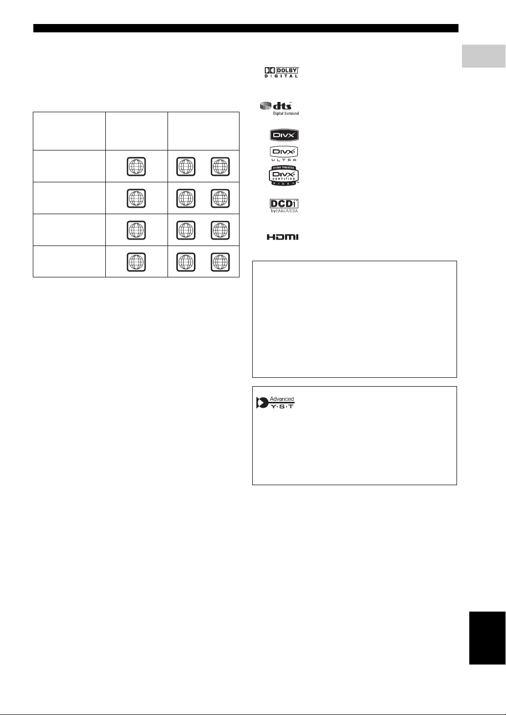
Region codes
The unit is designed to support the Region Management
System. Check the region code number on the disc
package. If the number does not match the unit’s region
number (see the table below or the back of the unit), the
unit may be unable to play the disc.
Destination
Europe
model
Australia
model
Korea, Asia and
Taiwan models
Russia
model
Region
code of
DVR-1000
2 2
4 4
3 3
5 5
Playable
discs
ALL
ALL
ALL
ALL
Sound field features
Manufactured under license from Dolby
Laboratories. “Dolby”, “Pro Logic”, “MLP
Lossless” and the double-D symbol are
trademarks of Dolby Laboratories.
“DTS” and “DTS Digital Surround” are
registered trademarks of DTS, Inc.
DivX, DivX Ultra Certified, and associated
logos are trademarks of DivX, Inc. and are used
under license.
“DCDi” is a trademark of Faroudja, a division
of Genesis Microchip, Inc.
HDMI, the HDMI logo and High Definition
Multimedia Interface are trademarks or
registered trademarks of HDMI Licensing LLC.
This product incorporates copyright protection
technology that is protected by method claims of
certain U.S. patents and other intellectual property
rights owned by Macrovision Corporation and other
rights owners. Use of this copyright protection
technology must be authorized by Macrovision
Corporation, and is intended for home and other
limited viewing uses only unless otherwise authorized
by Macrovision Corporation. Reverse engineering or
disassembly is prohibited.
1
INTRODUCTION
Active Servo Processing Subwoofer System with built-in
power amplifier.
This subwoofer system (NX-SW1000) employes Advanced
Yamaha Active Servo Technology which Yamaha has
developed for reproducing higher quality super-bass sound.
This super-bass sound adds a more realistic, theater-in-thehome effect to your stereo system.
English
3 En
Page 6
Introduction
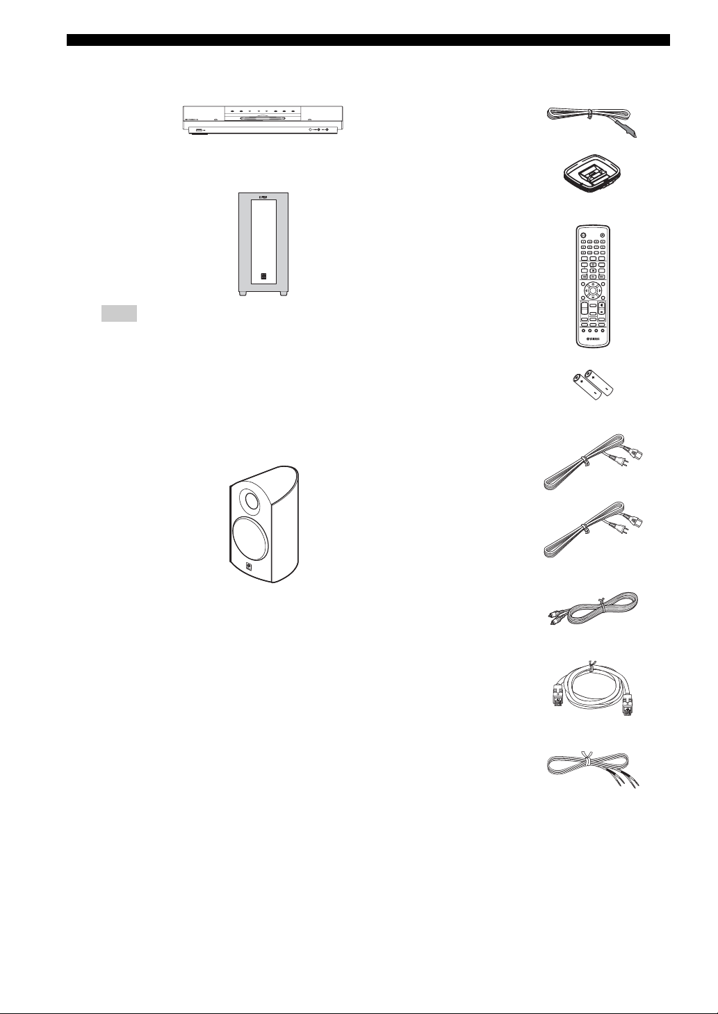
■ Main unit ■ Supplied accessories
DVD receiver
(DVR-1000)
Subwoofer
(NX-SW1000)
Note
Be sure to connect the power cable of the
subwoofer (NX-SW1000) to the AC outlet
before you turn on the DVD receiver (DVR-
1000). Otherwise, the subwoofer (NX-SW1000)
will not be powered correctly.
Front speakers (x2)
(NX-P1000)
Indoor FM antenna
AM loop antenna
(Asia, Australia, Korea,
and Taiwan models only)
Remote control
Batteries (x 2)
Power cable
(For DVR-1000)
Power cable
(For NX-SW1000: except
Europe and Russia models)
STANDBY/ON
BASS TREBLE
FREQ/TEXT
REPEAT
MODE START
A-B
PRESET PRESET
ON SCREEN
SET UP
AREA
MODE
ENHANCER
SURROUND
AUX
SUBTITLE
ANGLE ZOOM AUDIO
EJECT
DIMMER
SLEEP
NIGHT
PROG
PTY SEEK
SHUFFLE
MENU
ENTER
TOP MENU
/RETURN
DIRECT
DVD/CD
MUTE
TUNER
USB
4 En
Video pin cable (1.4 m)
System control cable (4 m)
(For NX-SW1000)
Speaker cables (4 m x 2)
(For NX-P1000)
Page 7
Functional overview
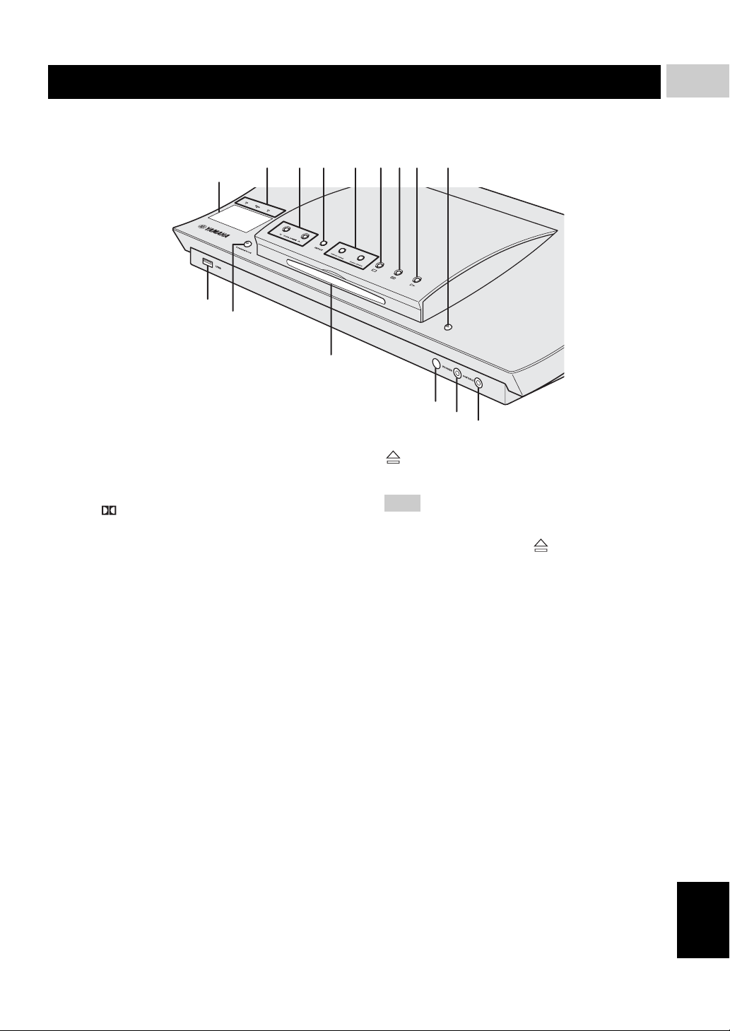
■ Top and front panels (DVR-1000)
1
INTRODUCTION
1
0
A
1 System display panel
Shows information about the operational status of the
unit.
2 PCM/ Digital/DTS indicator
Indicates the format of the audio being played back.
3 d VOLUME u
Adjusts the volume level.
4 INPUT
Selects input source or sets the priority level for the
audio input signals.
5 b/w, f/a
DVD/CD mode: selects the previous/next track or
chapter. Press and hold to fast forward or fast reverse.
TUNER mode: tunes the radio preset up/down.
USB mode: selects the previous/next track. Press and
hold to fast forward or fast reverse.
6 s
Exits an operation.
DVD/CD mode: stops disc playback.
TUNER mode: erases a preset radio station in Preset
mode if held more than two seconds, or stops preset
radio station installation in Auto Preset mode.
USB mode: stops playback.
7 e
DVD/CD mode: pauses disc playback.
USB mode: pauses playback.
7 8 965432
B
C
9
Ejects a disc in the DVD receiver.
Note
Do not push the ejected disc when reloading it. To
reload the ejected disc, press or h, or remove the
disc from the disc loading slot fully, then insert it to
the disc loading slot once again.
0 USB terminal
Connect to the USB connector of your USB device
(see page 19).
A STANDBY/ON
Turns on the DVD receiver, or sets it to the standby
mode (see “Turning the auto standby function on/off”
on page 35).
B Disc loading slot
Insert a disc to be played.
C Remote control sensor
Point the remote control towards this sensor.
D PHONES jack
Connects headphones.
E PORTABLE jack
Connects a portable audio player.
When this input source is selected, “FRONT IN”
appears on the system display panel.
D
E
English
8 h
DVD/CD mode: starts disc playback.
USB mode: starts playback.
5 En
Page 8

Functional overview
■ Rear panel (DVR-1000)
(Europe model)
21 4 5
3
AUX IN
SYSTEM
DIGITAL IN
OPTICAL
TO SUBWOOFER
CONNECTOR
MAINS
LRL
PCM/DTS
AUDIO
q
DIGITAL
67
1 AC inlet
Connect the supplied power cable.
2 COMPONENT VIDEO OUT jacks
Connect to the Y P
B/CB PR/CR jacks on your TV (see
page 14).
3 VIDEO output jack
Connect to the video (composite) jack on your TV
(see page 14).
4 FM ANT terminal
Connect the FM antenna.
5 GND and AM ANT terminals
Connect the AM loop antenna.
6 SYSTEM CONNECTOR terminal
Connect the subwoofer.
Y
LINE OUT
PB
R
P
R
COMPONENT
0 A
98
VIDEO
S VIDEO
VIDEO OUT
(DVD ONLY)
AV MONITOR OUT
(
DVD ONLY
)
HDMI
B
7 OPTICAL DIGITAL IN jack
Connect to the DIGITAL OUT jack on your digital
audio component.
8 AUX IN jacks
Connect to the AUDIO OUT jacks on your VCR or
cassette deck.
9 LINE OUT jacks
Connect to the AUDIO IN jacks on your VCR.
0 S VIDEO output jack
Connect to the S-video jack on your TV or VCR.
A AV MONITOR OUT terminal
(Europe and Russia models only)
Connect to your TV (see page 14).
B HDMI terminal
Connect to the HDMI input terminal of your HDMI
component (see page 15).
TUNER
GND
FM
AM
ANT
ANT
75Ω UNBAL
6 En
Page 9
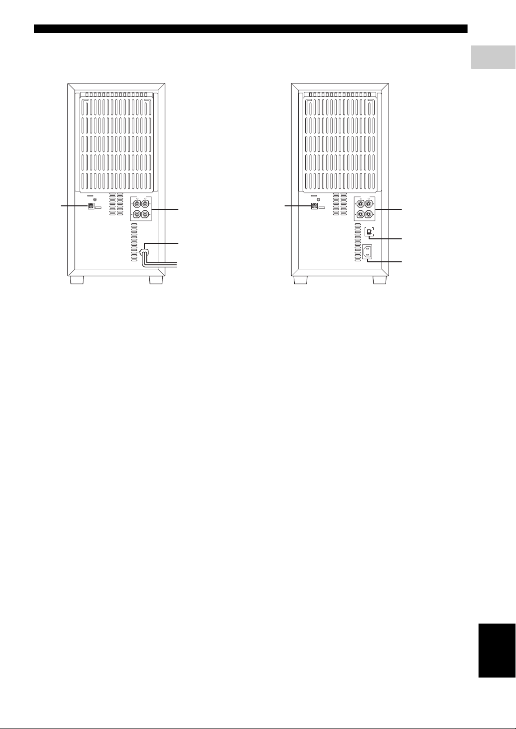
■ Rear panel (NX-SW1000)
Functional overview
1
INTRODUCTION
SPEAKERS
R
L
1
CONNECTOR
SYSTEM
6
Ω
MIN. /SPEAKER
MAINS
1 SYSTEM CONNECTOR terminal
Connect to the DVD receiver.
2 SPEAKER terminals
Connect to the speakers.
3 AC power cord
Connect to a standard AC outlet.
2
3
SPEAKERS
R
L
1
CONNECTOR
SYSTEM
6
Ω
MIN. /SPEAKER
VOLTAGE
SELECTOR
110V-120V
220V-240V
AC IN
(except Europe and Russia models)(Europe and Russia models)
1 SYSTEM CONNECTOR terminal
Connect to the DVD receiver.
2 SPEAKER terminals
Connect to the speakers.
3 VOLTAGE SELECTOR
Select the voltage according to your region.
4 AC inlet
Connect the supplied power cable.
2
3
4
7 En
English
Page 10
Functional overview
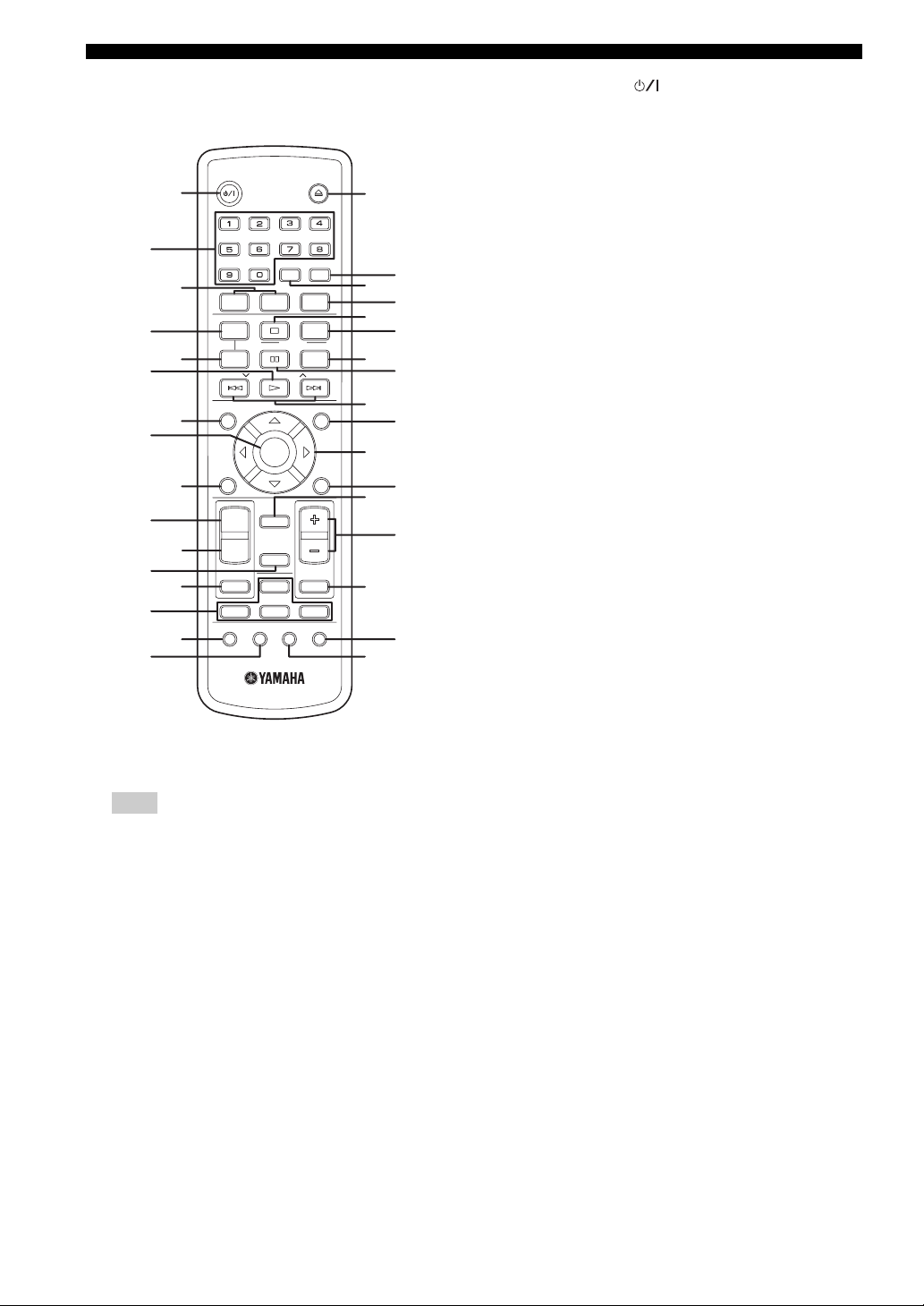
■ Remote control (For DVR-1000)
STANDBY/ON
1
2
4
6
8
0
B
D
F
3
5
7
9
A
C
E
BASS TREBLE
FREQ/TEXT
REPEAT
MODE START
A-B
PRESET PRESET
ON SCREEN
ENTER
SET UP
AREA
DIRECT
MODE
ENHANCER
DVD/CD
SURROUND
TUNER
AUX
SUBTITLE
ANGLE ZOOM AUDIO
DIMMER
PTY SEEK
EJECT
SLEEP
NIGHT
PROG
SHUFFLE
MENU
TOP MENU
MUTE
USB
/RETURN
G
I
K
M
O
Q
S
U
W
J
L
H
N
P
R
t
V
1 STANDBY/ON ( )
Turns on the DVD receiver, or sets it to the standby
mode.
2 Numeric keypad (0 – 9)
Enters a track/title number of the disc.
Enters a number of a preset radio station.
3 TREBLE/BASS
Selects the TREBLE (high tone) or BASS (low tone)
sound mode.
Use the VOLUME control to change the tone level.
4 REPEAT
Selects various repeat modes.
FREQ/TEXT
TUNER mode: switches the information display when
receiving Radio Data System.
5 REPEAT A-B
Repeats a specific section on a disc.
6 h
DVD/CD mode: starts disc playback.
USB mode: starts playback.
7 ON SCREEN
Displays the current status or disc information.
8 ENTER
Confirms a selection.
9 SET UP
Enters or exits the system setup menu.
0 AREA
Select either the WIDE or NARROW listening area
(see page 47).
Note
For details on how to use the remote control, see page 20.
8 En
A MODE
Select the Virtual Surround mode (see page 47).
B ENHANCER
Switches the Enhancer mode on or off (see page 47).
C SURROUND
Turns the surround effect on or off (see page 47).
D Input selection buttons
Selects the appropriate active source mode.
DVD/CD: switches to DVD/CD mode.
AUX: switches to ANALOG/FRONT IN/DIGITAL
input.
TUNER: switches to tuner (FM/AM) input.
USB: switches to USB mode. Accesses the contents of
the connected USB device or exits from the USB
mode (see page 31).
E SUBTITLE
Selects a subtitle language.
F ANGLE
Selects a DVD disc camera angle (if available).
Page 11

Functional overview
G EJECT ( )
Ejects a disc in the DVD receiver.
H SLEEP
Sets the sleep timer (see page 49).
I DIMMER
Selects different levels of brightness for the display
panel (see page 49).
J NIGHT
Turns the Night listening mode on or off
(see page 48).
K s
Exits an operation.
DVD/CD mode: stops disc playback.
DVD/CD mode: holding down the button will eject
the disc.
TUNER mode: erases a preset radio station if held for
more than two seconds.
USB mode: stops playback.
L PROG
DVD/CD mode: starts programming.
TUNER mode: starts automatic/manual preset
programming if held for more than two seconds.
M SHUFFLE
Plays tracks in random order.
PTY SEEK START
TUNER mode: starts searching for a Radio Data
System station.
frequency.
TUNER mode: press up or down to select auto tuning.
R TOP MENU/RETURN
Returns to the previous menu.
Displays the top-level disc menu
(if available).
S DIRECT
Switches the video output on or off during audio disc
playback.
This function (Audio Direct) is not available for
HDMI output.
In the DIRECT mode, the display panel dims to “DIM
2 (40% brightness)”.
T VOLUME (+/–)
Adjusts the volume level.
U MUTE
Mutes or restores the volume.
V AUDIO
Selects an audio language (DVD) or an audio channel
(VCD).
W ZOOM
Enlarges or reduces the TV screen picture.
1
INTRODUCTION
N e
DVD/CD mode: pauses disc playback.
USB mode: pauses playback.
PTY SEEK MODE
TUNER mode: sets the DVD receiver to the PTY
SEEK mode.
O b / a
DVD/CD mode: selects the previous/next track or
chapter. Press and hold to fast forward or fast reverse.
USB mode: selects the previous/next track. Press and
hold to fast forward or fast reverse.
d PRESET u
TUNER mode: press to select a preset radio station.
P MENU
Enters or exits the disc contents menu.
For VCD version 2.0 only:
In stop mode, turns on/off playback control (PBC)
mode.
During playback, returns to the main menu.
Q Cursors ( / / / )
Selects movement direction in the menu.
TUNER mode: press left or right to tune the radio
English
9 En
Page 12
PREPARATION
Connections
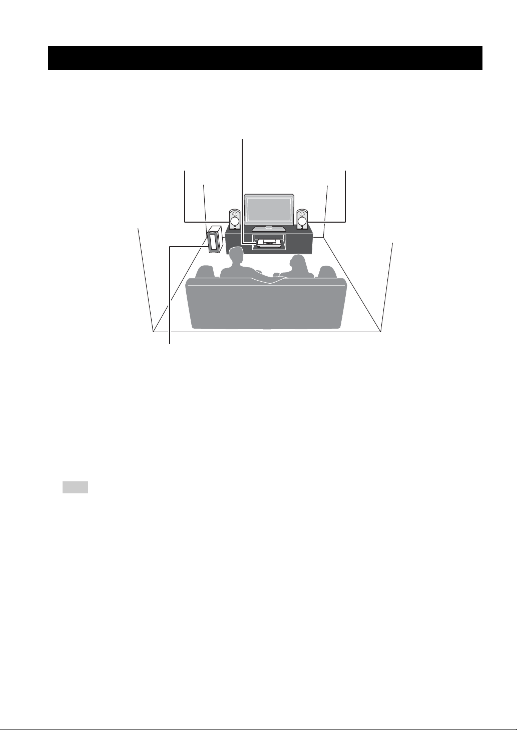
■ Roles and layout of the speakers
To enjoy quality sounds you need to place the speakers in their appropriate positions and install them correctly.
The following show the recommended layout of the speakers.
DVD receiver
Front
speaker (L)
For the best possible surround sound, all of the speakers (except the subwoofer) should be placed at the same distance
from the listening position.
1 Front Speakers (L, R)
Place the front left/right speakers on both sides of your TV at equal distances.
Main roles: Produces front channel (stereo) sounds and effect sounds.
2 Subwoofer
Place the subwoofer near a front speaker and turn it slightly toward the center of the room to reduce wall reflections.
Main roles: Produces bass sounds and low frequency (LFE) sounds contained in Dolby Digital or DTS.
1
Subwoofer
2
Front
1
speaker (R)
Note
To avoid magnetic interference, do not position the front speakers too close to your TV.
Allow adequate ventilation around the DVD receiver and subwoofer.
Bass sounds produced by the subwoofer may be heard differently depending on the listening position and subwoofer location.
To enjoy desired sounds, try to change the location of the subwoofer according to the listening position.
10 En
Page 13
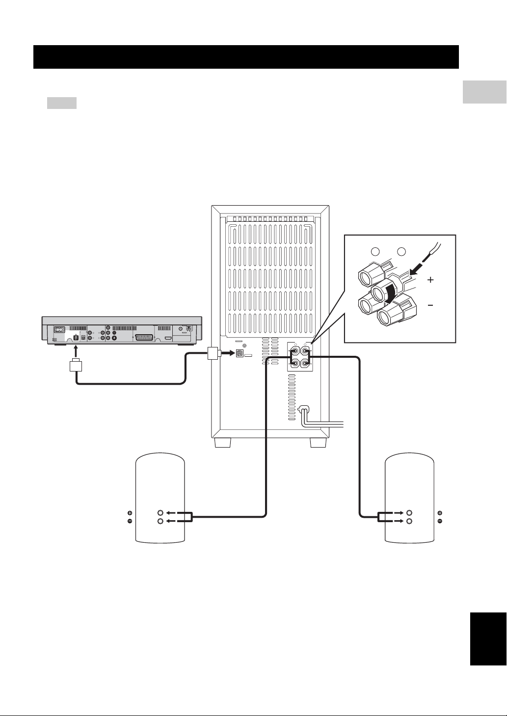
System connections
■ Connecting the speakers
Notes
– Do not connect the power cord of the subwoofer and DVD receiver into an AC outlet until all cable connections
are completed.
– Be sure to connect the end of the supplied speaker cable (where the red and black cable lengths differ) to the front
speaker, and leave some slack.
– Be sure to connect the red cable to the red terminal (subwoofer and front speakers) and the black cable to the
black terminal.
Subwoofer
R L
DVD receiver
DIGITAL IN
OPTICAL
CONNECTOR
MAINS
TO SUBWOOFER
PCM/DTS
q
DIGITAL
VIDEO
PB
LRL
R
COMPONENT
AUDIO
AV MONITOR OUT
VIDEO OUT
(DVD ONLY)
R
P
S VIDEO
Y
AUX IN
LINE OUT
SYSTEM
TUNER
GND
FM
AM
(
DVD ONLY
ANT
)
ANT
75Ω UNBAL
HDMI
SYSTEM
CONNECTOR
SPEAKERS
R
6
ΩMIN. /SPEAKER
L
2
PREPARATION
Front speaker (R)
MAINS
Front speaker (L)
English
11 En
Page 14
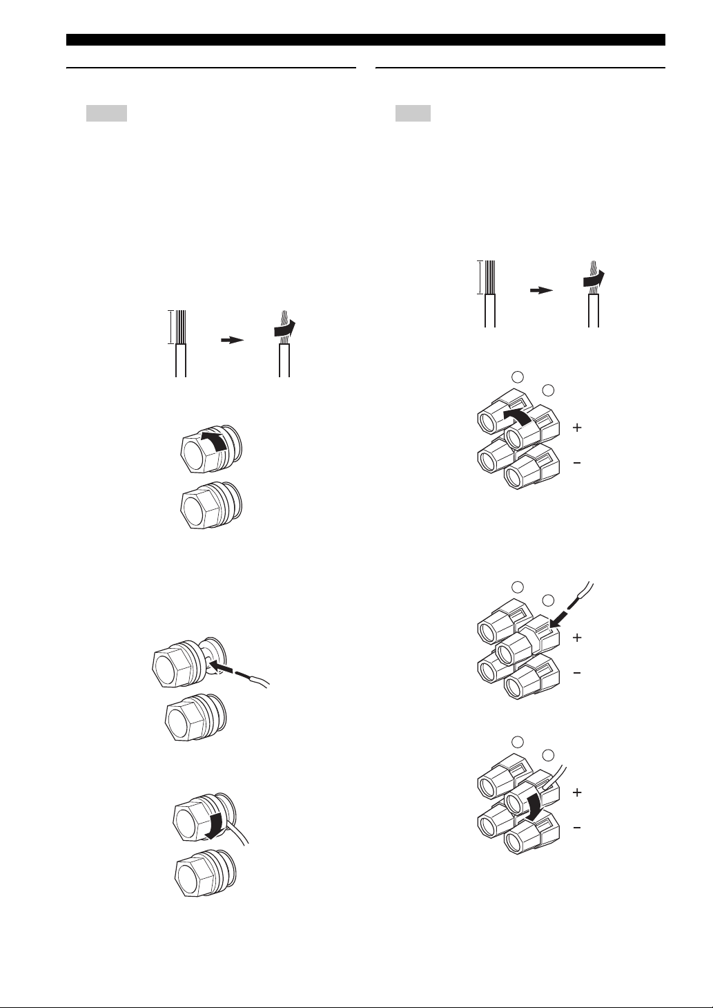
System connections
Connecting the speaker cables
Notes
– Be sure to connect the end of the supplied speaker
cable (where the red and black cable lengths differ)
to the front speaker, and leave some slack.
– Be sure to connect the red cable to the red terminal
(subwoofer and front speakers) and the black cable
to the black terminal.
1 Remove approximately 10 mm (0.4 in) of insulation
from the end of each speaker cable and then twist the
exposed wires of the cable together to prevent short
circuits.
10 mm (0.4 in)
2 Loosen the knob.
Connecting the subwoofer
Note
Be sure to connect the red cable to the red terminal
(subwoofer and front speakers) and the black cable to the
black terminal.
1 Remove approximately 10 mm (0.4 in) of insulation
from the end of each speaker cable and then twist the
exposed wires of the cable together to prevent short
circuits.
10 mm (0.4 in)
2 Loosen the knob.
R
L
Red: positive (+)
Black: negative (–)
3 Insert one bare wire into the hole in the center of each
terminal.
4 Tighten the knob to secure the wire.
Red: positive (+)
Black: negative (–)
3 Insert one bare wire into the hole on the side of each
terminal.
R
L
4 Tighten the knob to secure the wire.
R
L
12 En
Page 15
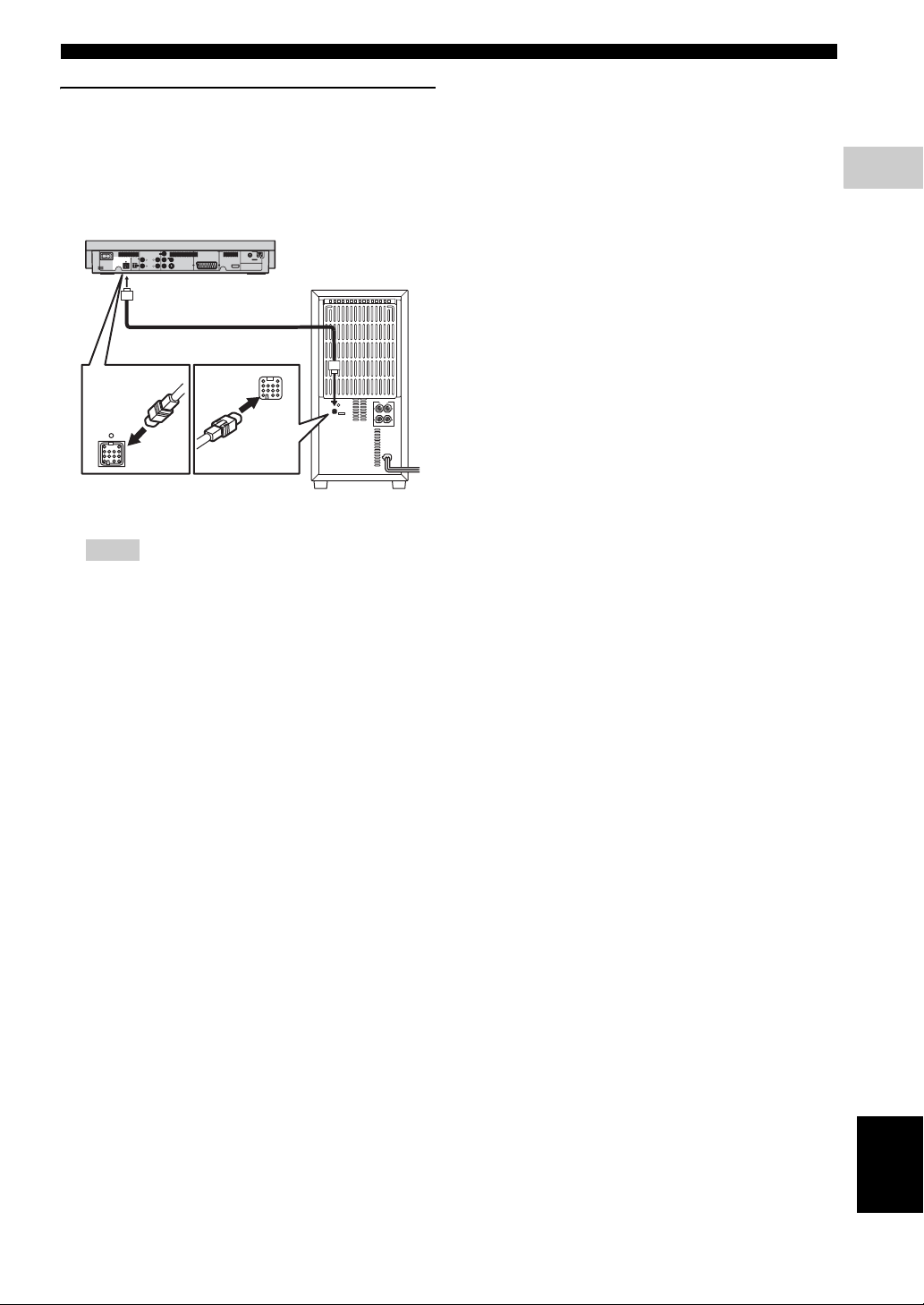
Connecting the DVD receiver and the
subwoofer
Connect the subwoofer to the DVD receiver using the
system control cable. Attach one end to the subwoofer and
the other to the SYSTEM CONNECTOR terminal at the
rear of the DVD receiver.
System connections
2
PREPARATION
MAINS
TO SUBWOOFER
SYSTEM
CONNECTOR
Y
AUX IN
LINE OUT
SYSTEM
DIGITAL IN
VIDEO
PB
OPTICAL
LRL
CONNECTOR
VIDEO OUT
(DVD ONLY)
P
R
R
S VIDEO
PCM/DTS
COMPONENT
AUDIO
q
DIGITAL
TUNER
GND
FM
AM
ANT
(
)
AV MONITOR OUT
DVD ONLY
ANT
75Ω UNBAL
HDMI
SPEAKERS
R
L
R
SYSTEM
CONNECTOR
SYSTEM
CONNECTOR
L
6
ΩMIN. /SPEAKER
MAINS
NX-SW1000
Notes
– When connecting the system control cable, be sure
to insert the plug until it clicks. When
disconnecting the system control cable, slide the
collar of the plug back to unlock.
– Ensure that the speaker cables are correctly
connected. Improper connections may damage the
system due to a short-circuit.
– When connecting the speakers, fix the speaker
cables in place so that cables do not loosen. If your
foot or hand accidentally gets caught on a loose
speaker cable, the speaker may fall.
– To prevent unwanted noise, do not place the
subwoofer too close to the DVD receiver, AC
power adaptor, TV or other sources of radiation.
– Be sure to connect the power cable of the
subwoofer (NX-SW1000) to the AC outlet before
you turn on the DVD receiver (DVR-1000).
Otherwise, the subwoofer (NX-SW1000) will not
be powered correctly.
13 En
English
Page 16
Other connections
O
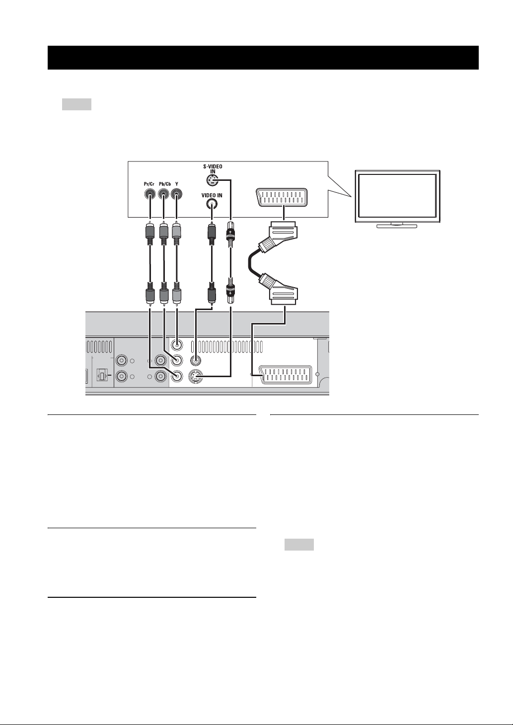
■ Connecting a TV
Notes
– You only need to make one video connection from the following options (A, B, C, or D), depending on the
capabilities of your TV.
– Do not connect the power cords until all cable connections are completed.
R
DIGITAL IN
OPTICAL
PCM/DTS
q
DIGITAL
AUX IN
<A>
LINE OUT
LRL
R
AUDIO
COMPONENT
<B>
Y
VIDEO
PB
R
P
S VIDEO
VIDEO OUT
(DVD ONLY)
<C>
COMPONENT VIDEO OUT jacks <A>
Use the component video cables (red/blue/green, not
supplied) to connect the DVD receiver’s Y P
B PR jacks to
the corresponding component video input jacks (or the Y
Pb/Cb Pr/Cr/ YUV jacks) on your TV.
Progressive scan video quality is only available when
using Y PB PR in conjunction with a progressive scan TV.
To activate the progressive scan function see “Progressive
function” on page 40.
VIDEO output jack <B>
Use a composite video cable (yellow -supplied) to connect
the DVD receiver’s VIDEO output jack to the video input
jack (or A/V In/Video In/Composite/Baseband jack) on
your TV.
S VIDEO output jack <C>
S (separate)-video connections achieve a clearer picture
than composite video connections. Use an S-video cable
(not supplied) to connect the DVD receiver’s
S VIDEO output jack to the S-video input jack (or Y/C or
S-VHS jack) on your TV.
AV MONITOR OUT
(
DVD ONLY
<D>
)
TV
AV MONITOR OUT terminal <D>
(Europe and Russia models only)
The SCART cable, or “Euro AV cable”, supports AV
MONITOR OUT signal transmission, providing you with
the best possible picture and sound. If your TV has only
one terminal for video input, and you want to connect it
directly to the DVD receiver, you can use the AV
MONITOR OUT connector. Connect one end of the
SCART cable to the AV MONITOR OUT connector and
the other end to the SCART connector on your TV.
Notes
– TV channels, if you use AV MONITOR OUT
terminal to connect the TV. To use AV MONITOR
OUT terminal, make sure to set the DVD
receiver’s component setting to “RGB” (see
page 22).
– When using AV MONITOR OUT terminal to
listen to the TV channels, set the DVD receiver’s
component setting to “RGB” (see page 22).
– S-video signal is not output at AV MONITOR
OUT terminal.
14 En
Page 17
Other connections
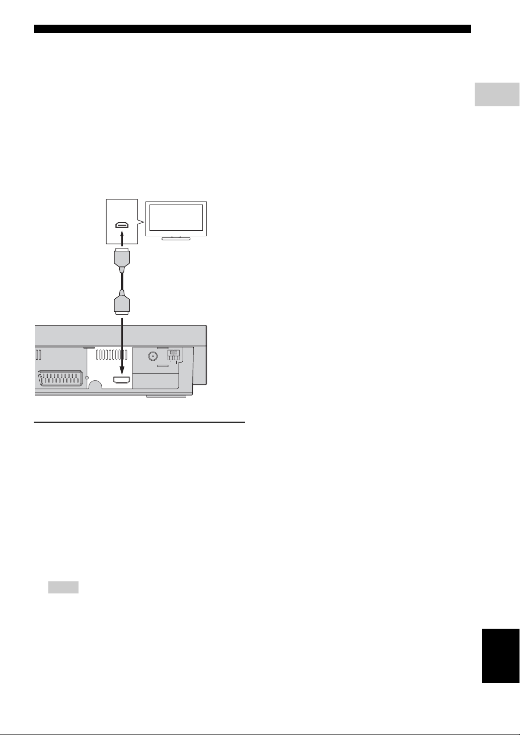
■ Connecting an HDMI component
HDMI (High-Definition Multimedia Interface) is the first
industry-supported, uncompressed, all-digital A/V (audio/
video) interface.
By connecting to an HDMI component (such as a TV),
you can enjoy standard, enhanced or high-definition video
as well as multi-channel digital audio using a single cable.
When used in combination with HDCP (High-bandwidth
Digital Content Protection), HDMI provides a secure
audio/video interface that meets the security requirements
of content providers and system operators.
For further information on HDMI, visit the HDMI website
at “http://www.hdmi.org/”.
HDMI
IN
TV
– Do not disconnect or connect the HDMI cable from
the DVD receiver or turn off the power of the
HDMI/DVI component connected to the HDMI
terminal of the DVD receiver while data is being
transferred. Doing so may disrupt playback or
cause noise.
2
PREPARATION
TUNER
AV MONITOR OUT
(
DVD ONLY
)
L
R
HDMI
GND
FM
AM
ANT
ANT
75Ω UNBAL
DVD receiver
Viewing and Listening to playback
from an HDMI component
1 Connect HDMI terminal of the DVD receiver to the
HDMI input terminal of your HDMI compatible
component using a commercially available HDMI
cable.
2 Select the appropriate audio output from [HDMI
AUDIO OUT] in [AUDIO SETUP PAGE] (see
page 36).
3 Select the appropriate video output from [HDMI
VIDEO] in [VIDEO SETUP PAGE] (see page 39).
Notes
– The DVD receiver is not compatible with HDCP-
incompatible HDMI or DVI components.
– You need a commercially available HDMI/DVI
conversion cable when you connect the DVD
receiver to other DVI components.
– When connecting an HDMI component, refer to
the instruction manual for the component.
English
15 En
Page 18
Other connections
HDMI audio output
HDMI AUDIO OUT
*2,3
*2
PCM 2-channel Off
DVD-Video
CD/MP3/WMA/
®
DivX
DTS-CD
Audio format Analog output
*1
Dolby Digital Multichannel
Dolby Digital
2-channel
DTS
Multi-channel
DTS 2-channel Multi
MPEG
Multi-channel
MPEG 2-channel Multi
PCM 2-channel
*4
Multi
Stereo
*1
Multi
/Stereo Dolby Digital
*1
Multi
Stereo
*1
/Stereo DTS
*1
Multi
Stereo
*1
/Stereo MPEG
Dolby Digital
DTS
MPEG
Multi*1/Stereo PCM 2-channel
2-channel Multi*1/Stereo PCM 2-channel
*1
Multi-channel
2-channel Multi
Multi
Stereo
*1
/Stereo DTS
DTS
AUTO PCM OFF
*2,3
*2
*2,3
*2
*2,3
*2
VCD 2-channel Multi*1/Stereo PCM 2-channel
*1
SVCD
Multi-channel
2-channel Multi
*1
The audio output is automatically changed from multi-channel audio signals to downmixed stereo signals.
*2
If the connected HDMI component does not support bitstream signals (Dolby Digital, DTS, and MPEG), the audio output is
Multi
Stereo
*1
/Stereo MPEG
MPEG
*2,3
*2
automatically changed from bitstream signals to PCM signals.
*3
If the connected HDMI component does not support multi-channel audio signals, the audio output is automatically changed from
PCM multi-channel signals to PCM stereo signals and 48 kHz/16 bits signals or less.
*4
If the connected HDMI component does not support more than 48 kHz, the audio output is automatically changed to 48 kHz/16 bits
signals or less.
Note
You need to set [HDMI AUDIO OUT] (see page 36).
16 En
Page 19
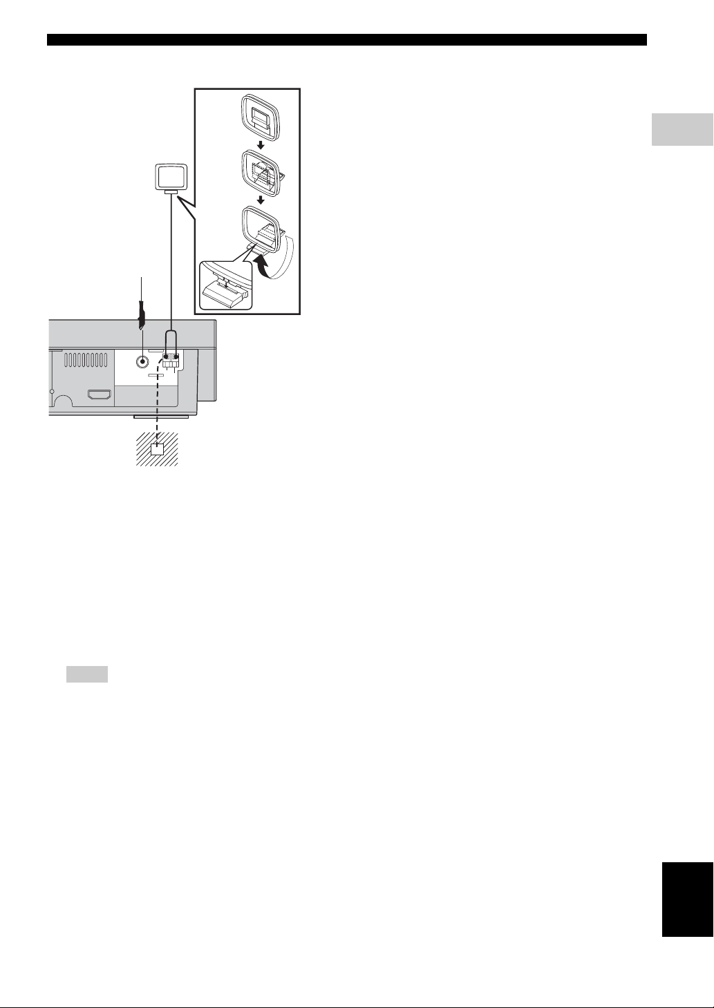
■ Connecting the FM/AM antennas
AM loop
antenna
1
Other connections
2
PREPARATION
FM antenna
2
TUNER
GND
FM
AM
ANT
ANT
75Ω UNBAL
HDMI
Ground (GND terminal)
For minimum interference, connect
the antenna GND terminal to a
good earth ground. A good earth
ground is a metal stake driven into
moist earth.
1 Connect an AM loop antenna to the AM ANT
terminal. Place the AM loop antenna on a shelf or
attach it to a stand or wall.
2 Connect an indoor FM antenna to the FM ANT
terminal. Extend the FM antenna and fix its ends to
the wall.
For better FM stereo reception, connect an external
FM antenna.
Notes
– Adjust the position of the antennas for optimal
reception.
– Position the antennas as far as possible from your
TV, VCR or other sources of radiation to prevent
unwanted interference.
17 En
English
Page 20
Other connections
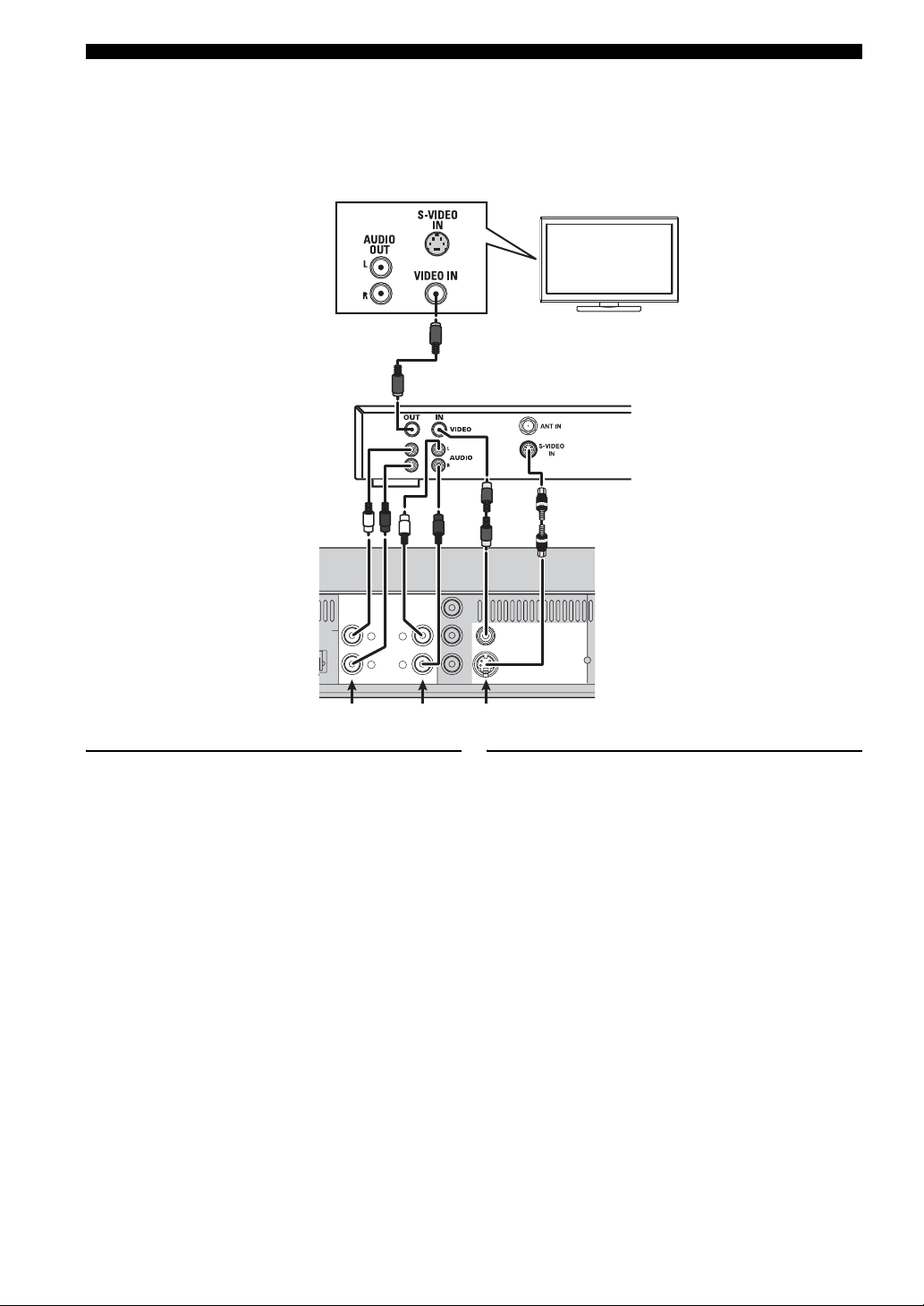
■ Connecting external AV components
If you connect external AV equipment such as a VCR, cassette deck or digital audio component to the following audio
terminals on the DVD receiver, you can enjoy those audio sources with the DVD receiver. Also, you can record AV
sources played on the DVD receiver using the recording equipment. This section provides some examples of other AV
equipment connections. For information on your AV equipment, refer to the manual provided.
TV
1
VCR (for example)
AUX IN
L IN
AL
DTS
ITAL
LINE OUT
LRL
R
AUDIO
2
Viewing and listening to playback
1 Connect the DVD receiver’s VIDEO output jack to
the VIDEO IN jack on your VCR. Or, connect the
VCR to the TV as shown.
2 Connect the DVD receiver’s AUX IN jacks to the
AUDIO OUT jacks on your VCR.
Before starting operation, press AUX to select
“ANALOG” in order to activate the input source.
Y
VIDEO
PB
VIDEO OUT
(DVD ONLY)
P
R
COMPONENT
S VIDEO
12
DVD receiver
Using the VCR for recording DVD
playback
Some DVDs are copy-protected. You cannot record or
dub protected discs using a VCR.
1 Connect the DVD receiver’s VIDEO output jack to
the VIDEO IN jack on your VCR. Or, connect the
DVD receiver’s S VIDEO output jack to the SVIDEO IN jack on your VCR.
2 Connect the DVD receiver’s LINE OUT jacks to the
AUDIO IN jacks on your VCR.
This will allow you to make analog stereo (two
channels, right and left) recordings.
18 En
Page 21

Other connections
■ Connecting a digital audio component
Digital audio
component
DIGITAL IN
OPTICAL
PCM/DTS
q
DIGITAL
AUX IN
TO SUBWOOFER
SYSTEM
CONNECTOR
Listening to playback
Connect the DVD receiver’s OPTICAL DIGITAL IN jack
to the DIGITAL OUT jack on a digital audio component.
Before starting operation, press AUX repeatedly to select
“DIGITAL” in order to activate the input source.
LINE OUT
LRL
R
AUDIO
DVD receiver
■ Connecting a USB device
USB terminal
The DVD receiver has a USB terminal and can access
MP3, WMA and AAC files saved on your USB device.
Connect the USB terminal on the front panel of the DVD
receiver to a USB connector of your USB device.
DVD receiver
USB
device
Notes
– The DVD receiver may not recognize some USB
devices.
– For details about the USB features, see “Using a
USB device” on page 31.
2
PREPARATION
Notes
– You cannot hear or record the MP3-CD playback if
you use a digital connection.
– Always refer to the owner’s manual of the
connected component for complete connection and
usage details.
English
19 En
Page 22

BASIC OPERATION
3
Getting started
■ Inserting batteries into the remote control
Press
1
1 Press on the battery cover and open the cover.
2 Insert the two supplied batteries (AA, R06, UM-3)
into the battery compartment.
Insert the batteries according to the polarity markings
(+ and -).
3 Close the battery cover.
To replace the batteries
If the batteries grow old, the effective operation distance
of the remote control decreases considerably. If this
happens, replace the batteries with two new ones as soon
as possible.
Notes
– Do not use an old battery together with new one.
– Do not use different types of batteries (for
example, alkaline and manganese) together. Each
type of battery has its own characteristics even if
they are similar in shape.
– If the batteries run out, immediately remove them
from the remote control to prevent an explosion or
acid leak.
– Dispose of the batteries according to the regional
regulations.
– If a battery starts leaking, dispose of it
immediately.
Be careful not to let leaking battery acid come into
contact with your skin or clothing. Before inserting
new batteries, wipe the compartment clean.
– Replace the batteries within two minutes to
preserve the memory in the remote control.
2
■ Using the remote control
Use the remote control within 6 m of the DVD receiver
and point it toward the remote control sensor.
Within 6 m
30˚ 30˚
STANDBY/ON
EJECT
DIMMER
SLEEP
BASS TREBLE
NIGHT
FREQ/TEXT
PROG
REPEAT
PTY SEEK
MODE START
A-B
SHUFFLE
PRESET PRESET
ON SCREEN
MENU
ENTER
TOP MENU
SET UP
/RETURN
AREA
DIRECT
MODE
ENHANCER
DVD/CD
SURROUND
MUTE
TUNER
AUX
USB
SUBTITLE
ANGLE ZOOM AUDIO
1 Use the input selection buttons on the remote control
to select the mode you wish to control (for example
DVD/CD).
→ The selected source mode appears in the display
panel.
2 Select the desired function (for example, h or b /
a).
Notes
– Be careful not to spill liquid on the remote control.
– Be careful not to drop the remote control.
– Do not leave the remote control in the following
places:
– hot or humid places, such as near a heater or in a
bathroom
– extremely cold places
– dusty places
20 En
Page 23

Getting started
■ Setting a TV
Notes
– Make sure you have completed all the necessary
connections (see “Connecting a TV” on page 14).
– To return to the previous menu, press .
– To exit from the menu, press SET UP.
– If the settings you have selected are not
appropriate, you can reset all settings to the initial
factory settings (see “Restoring to the factory
defaults” on page 43).
1 Press DVD/CD.
→ “DVD/CD” appears in the display panel.
2 Turn on the TV and set to the correct video-in
channel.
→ You should see the background screen on the TV.
–
Usually this channel is between the lowest and
highest channels and may be called FRONT, A/V IN
or VIDEO. See your TV manual for more details.
–
Or, you may go to channel 1 on your TV, then press
the Channel down button repeatedly until you see the
Video In channel.
–
Or, the TV remote control may have a button or
switch that chooses different video modes.
Selecting the TV type
In order for a DVD to play on this DVD receiver, the color
system of the DVD, the TV and the DVD receiver should
match. Before changing the TV system, determine the
color system of your TV.
1 In DVD/CD mode, press SET UP.
2 Press / repeatedly to select [VIDEO SETUP
PAGE].
4 Press / to highlight one of the options below:
PA L – Select this if the connected TV has the PAL
color system. It will change the video signal of an
NTSC disc and output it to PAL format.
NTSC – Select this if the connected TV has the NTSC
color system. It will change the video signal of a PAL
disc and output it to NTSC format.
MULTI – Select this if the connected TV is compatible
with both NTSC and PAL (multisystem). The output
format will be in accordance with the video signal of
the disc.
5 Select a setting and press ENTER.
–
Follow the instructions shown on the TV to confirm
the selection (if any).
–
If a blank/distorted TV screen appears, wait for 15
seconds for auto recovery to activate.
Selecting color system by using the
remote control
STANDBY/ON
ON SCREEN
SET UP
DIMMER
BASS TREBLE
FREQ/TEXT
REPEAT
PTY SEEK
MODE START
SHUFFLE
A-B
PRESET PRESET
ENTER
AREA
DIRECT
MODE
ENHANCER
SURROUND
DVD/CD
TUNER
AUX
SUBTITLE
ANGLE ZOOM AUDIO
EJECT
SLEEP
NIGHT
PROG
MENU
TOP MENU
/RETURN
MUTE
USB
AUDIO
3
BASIC OPERATION
3 Press / to highlight [TV TYPE], then press
.
VIDEO SETUP PAGE
TV TYPE PAL
TV DISPLAY NTSC
PICTURE SETTING MULTI
ADV PICTURE
PROGRESSIVE
COMPONENT
1 If a disc is inserted, press to eject the disc.
2 Press , then press AUDIO.
→ If the default setting of the color system is NTSC,
it will be changed to PA L.
→ If the default setting of the color system is PAL, it
will be changed to NTSC.
English
21 En
Page 24

Getting started
Setting the TV display
Set the aspect ratio of the DVD receiver according to the
TV you have connected. The format you select must be
available on the disc. If it is not, the TV display setting
will not affect the picture during playback.
1 In DVD/CD mode, press SET UP.
2 Press / repeatedly to select [VIDEO SETUP
PAGE].
3 Press / to highlight [TV DISPLAY], then
press .
VIDEO SETUP PAGE
TV TYPE
TV DISPLAY
PICTURE SETTING
ADV PICTURE
PROGRESSIVE
COMPONENT YUV
RGB
4 Press / to highlight one of the options below:
YUV – Select this for Y P
B PR or S-Video
connections.
RGB – Select this for AV MONITOR OUT
connections.
VIDEO SETUP PAGE
TV TYPE
TV DISPLAY 4:3 PAN SCAN
PICTURE SETTING 4:3 LETTER BOX
ADV PICTURE 16:9
PROGRESSIVE
COMPONENT
4 Press / to highlight one of the options below:
4:3 PAN SCAN – Select this if you have a
conventional TV and want both sides of the picture to
be trimmed or formatted to fit your TV screen.
4:3 LETTER BOX – Select this if you have a
conventional TV. In this case, a wide picture with
black bands on the upper and lower portions of the TV
screen will be displayed.
16:9 – Select this if you have a wide-screen TV.
5 Select a setting and press ENTER.
Selecting the color system
(Europe and Russia models only)
This setting allows you to toggle the video signal output
between YUV (Y P
RGB (AV MONITOR OUT connections).
B PR or S-Video connections) and
5 Select a setting and press ENTER.
6 To return to the previous menu, press .
To exit the menu, press SET UP.
Note
AV MONITOR OUT (SCART) connections are only
available for Europe and Russia models.
1 In DVD/CD mode, press SET UP.
2 Press / repeatedly to select [VIDEO SETUP
PAGE].
3 Press / to highlight [COMPONENT], then
press .
22 En
Page 25

■ Setting language preferences
You can select your preferred language settings so that
this receiver will automatically switch to your preferred
language whenever you load a disc. If the language
selected is not available on the disc, the disc’s default
setting language will be used instead. The OSD (on-screen
display) language for the system menu will remain as you
set it, regardless of various disc languages.
Notes
– To return to the previous menu, press .
– To exit from the menu, press SET UP.
– If the settings you have selected are not
appropriate, you can reset all settings to the initial
factory settings (see “Restoring to the factory
defaults” on page 43).
On-screen display (OSD) language
1 In DVD/CD mode, press SET UP.
2 Press / to select [GENERAL SETUP PAGE].
3 Press / to highlight [OSD LANGUAGE],
then press .
GENERAL SETUP PAGE
DISC LOCK ENGLISH
PROGRAM DANSK
OSD LANGUAGE DEUTSCH
SCREEN SAVER ESPAÑOL
AUTO STANDBY FRANÇAIS
DIVX(R) VOD CODE ITALIANO
NEDERLANDS
NORSK
Getting started
Audio, Subtitle and Disc menu
languages
1 Press s twice to stop playback (if any), then press
SET UP.
2 Press / repeatedly to select [PREFERENCE
PAGE].
3 Press / to highlight one of the options below
at a time, then press .
– [AUDIO] (disc’s soundtrack)
– [SUBTITLE] (disc’s subtitles)
– [DISC MENU] (disc’s menu)
PREFERENCE PAGE
AUDIO ENGLISH
SUBTITLE CHINESE
DISC MENU FRENCH
PARENTAL JAPANESE
PBC SPANISH
MP3/JPEG NAV PORTUGUESE
VR LIST POLISH
PASSWORD ITALIAN
4 Press / to select a language and press
ENTER to confirm.
If the language you want is not in the list, then select
[OTHERS].
Use the numeric keypad (0-9) on the remote control
to enter the 4-digit language code (see “LIST OF
LANGUAGE CODES” at the end of this manual”)
and press ENTER to confirm.
5 Repeat steps 3 and 4 for other settings.
3
BASIC OPERATION
4 Press / to select a language and press
ENTER to confirm.
English
23 En
Page 26

Getting started
■ Setting speaker channels
You can adjust the delay times and volume level for
individual speakers. This adjustment lets you optimize the
sound of your system to best suit your surroundings and
setup.
Notes
– To return to the previous menu, press .
– To exit from the menu, press SET UP.
– If the settings you have selected are not
appropriate, you can reset all settings to the initial
factory settings (see “Restoring to the factory
defaults” on page 43).
1 Press / repeatedly to select [AUDIO SETUP
PAGE].
2 Press / to highlight [SPEAKER], then press
.
AUDIO SETUP PAGE
HDMI AUDIO OUT
SPEAKER
CD UPSAMPLING
LIP SYNC
3 Press / to adjust the setting that best suit your
surround sound needs.
You can adjust the volume level for the individual
speakers from -6dB to +6dB.
SPEAKER VOLUME SETUP
FRONT LEFT
FRONT RIGHT
SUBWOOFER
0db
0db
0db
4 Press ENTER to confirm.
Note
A test tone will be automatically generated to help you judge
the sound level of each speaker.
→ The [SPEAKER] menu appears.
24 En
Page 27

OPERATIONS
Disc operation
IMPORTANT!
– If the inhibit icon ( or ) appears on the TV
screen when a button is pressed, the function for
that button is not available on the current disc or at
the current time.
– DVD discs and players are designed with regional
restrictions. Before playing a disc, make sure the
disc is for the same zone as your receiver.
– Do not insert any objects other than discs into the
disc loading slot. Doing so may cause the disc
player to malfunction.
■ Playing discs
1 Press DVD/CD until “DVD/CD” appears in the display
panel.
2 Turn on the TV power and set to the correct Video In
channel (see “Setting a TV” on page 21).
→ You should see the background screen on the TV.
3 Insert the disc into the disc loading slot.
4 Playback will start automatically.
→ If a disc menu shows on the TV, see “Using the
disc menu” on page 27.
→ If the disc is locked by parental control, you must
enter your six-digit password (see “Restricting
playback with parental control” on page 41).
■ Basic playback controls
STANDBY/ON
Numeric
keypad (0-9)
e
ON SCREEN
SET UP
SUBTITLE
To pause playback
During playback, press e.
– To resume normal playback, press h.
To select another track/chapter
Press b / a or use the numeric keypad (0-9) to
enter a track/chapter number.
–
During repeat playback of a track/chapter, pressing
b / a replays the same track/chapter.
To search backward/forward
Press and hold b / a (or / ).
– To resume normal playback, press h.
–
While searching, press b / a (or / ) again to
increase the search speed.
To stop playback
Press s.
DIMMER
NIGHT
BASS TREBLE
FREQ/TEXT
PROG
REPEAT
PTY SEEK
MODE START
SHUFFLE
A-B
PRESET PRESET
ENTER
AREA
DIRECT
MODE
ENHANCER
MUTE
SURROUND
DVD/CD
TUNER
AUX
ANGLE ZOOM AUDIO
EJECT
SLEEP
USB
MENU
TOP MENU
/RETURN
s
h
b / a
4
OPERATIONS
25 En
English
Page 28

Disc operation
■ Selecting various repeat shuffle functions
Repeat playback
Repeat chapter/title/disc (DVD-Video)
Each time you press REPEAT, the display changes as
follows:
CHAPTER
TITLE
DISC
REPEAT OFF
CHAPTER*: repeats the current chapter.
TITLE*: repeats the current title.
DISC*: repeats the entire disc.
REPEAT OFF: exits repeat mode.
* This feature may not be available with some discs.
Repeat track/disc
(except DVD-Video)
Each time you press REPEAT, the display changes as
follows:
Repeating a section within a chapter/
track
1 While playing a disc, press A-B at your chosen
starting point.
2 Press A-B again at your chosen end point.
→ The section will now repeat continuously.
3 To exit the sequence, press A-B.
Shuffle (except VR format disc)
With the Shuffle function, you can play tracks in random
order.
– During playback, press SHUFFLE repeatedly to
select between SHUFFLE, SHUFFLE REPEAT
and SHUFFLE OFF.
→ The selected mode appears in the display for
several seconds.
– In SHUFFLE mode, all tracks on the disc currently
playing are played in random order.
– In SHUFFLE REPEAT mode, all tracks are played
in random order and continuously.
TRACK
DISC
REPEAT OFF
TRACK: repeats the current track.
DISC: repeats the entire disc.
REPEAT OFF: exits repeat mode.
Note
For VCD, repeat playback is not possible if the PBC
mode is selected.
26 En
Page 29

■ Other operations for video playback (DVD/VCD/SVCD)
STANDBY/ON
FREQ/TEXT
PRESET PRESET
ON SCREEN
SUBTITLE
ON SCREEN
SET UP
SUBTITLE
ANGLE
Using the disc menu
Depending on the disc, a menu may appear on the TV
screen once you load the disc.
To select a playback feature or item
Use / / / or the numeric keypad (0-9)
on the remote control, then press ENTER to start
playback.
To access or remove the menu
Press MENU on the remote control.
Displaying disc information and the
current status
BASS TREBLE
REPEAT
A-B
AREA
MODE
SURROUND
AUX
ANGLE ZOOM AUDIO
DIMMER
PTY SEEK
MODE START
SHUFFLE
ENTER
DIRECT
ENHANCER
DVD/CD
TUNER
EJECT
SLEEP
NIGHT
PROG
MENU
TOP MENU
/RETURN
MUTE
USB
MENU
TOP MENU/
RETURN
AUDIO
ZOOM
Disc operation
1 During playback, press ON SCREEN.
→ A list of available disc information appears on the
TV screen.
DVD
MENU
TITLE 02/14
CHAPTER 02/14
AUDIO 5.1CH
SUBTITLE ENG
BITRATE 16 TITLE ELAPSED 0:02:25
VCD/SVCD
MENU
TRACK 02/14
DISC TIME 0:49:17
TRACK TIME 0:03:43
REPEAT OFF
BITRATE 16 TOTAL ELAPSED 0:02:25
2 Press / to view the information and press
ENTER to access.
3 Use the numeric keypad (0-9) to enter the number/
time or press / to make the selection, then
press ENTER to confirm.
→ Playback will change to the chosen time or to the
selected title/chapter/track.
Zooming in
This function allows you to enlarge the picture on the TV
screen and pan through the enlarged picture.
1 During playback, press ZOOM repeatedly to select a
different zoom factor.
Use / / / to move through the zoomed
image.
→ Playback continues.
4
OPERATIONS
You can display disc information and the disc’s current
status (for example, title or chapter number, elapsed
playing time, audio/subtitle language). A number of
operations can be performed without interrupting disc
playback.
2 Press ZOOM repeatedly to return to the original size.
Resuming playback from the last
stopped point
You can resume playback of the last 10 discs, even if the
disc was ejected or this receiver’s power switched off.
1 Load one of the last played 10 discs.
→ “LOAD” appears.
2 Press h and the disc will be played back from the last
stop point.
English
To cancel the resume mode
In stop mode, press s again.
27 En
Page 30

Disc operation
Advancing by frame
1 During playback, press e on the remote control.
→ Play will pause and sound will be mute.
2 Press e again to select the next picture frame.
3 To resume normal playback, press h.
Changing sound track language
This operation works only on DVDs (or a connected
digital audio component) with multiple language
soundtracks, you can change the language while playing a
DVD (or a connected digital audio component).
Press AUDIO repeatedly to select the available audio
languages.
For VCD - changing the audio channel
Press AUDIO repeatedly to select the available audio
channels provided by the disc (STEREO, MONO LEFT,
MONO RIGHT or MIX-MONO).
Changing subtitle language (DVD only)
This operation works only on DVDs with multiple subtitle
languages, you can change the language you want while
playing a DVD.
Press SUBTITLE repeatedly to select from the various
subtitle languages.
Viewing from another angle (DVD
only)
If the disc contains sequences recorded from different
camera angles, this function allows you to view the picture
from a number of different angles.
Press ANGLE repeatedly to select the desired angle.
→ Playback changes to the selected angle.
Selecting a title (DVD only)
Some DVDs may contain several titles. If the disc has
been recorded with a title menu recorded on it, you can
start playback from the selected movie title.
1 Press TOP MENU/RETURN.
→ The disc title menu appears on the TV screen.
2 Use / / / or the numeric keypad (0-
9) to select a play option.
3 Press ENTER to confirm.
Playback control (PBC) (VCD only)
PBC playback allows you to play Video CDs
interactively, following the menu on the display.
This function can also be accessed via the
‘PREFERENCE PAGE’ menu (see “PBC” on page 42).
For VCDs with Playback Control (PBC)
feature (version 2.0 only)
With playback stopped, press MENU to toggle between
‘PBC ON’ and ‘PBC OFF’.
→ If you select ‘PBC ON’, the disc menu (if available)
will appear on the TV. Use b / a or the numeric
keypad (0-9) to select a play option and press ENTER to
confirm.
→ If you select ‘PBC OFF’, the VCD will skip the index
menu and playback directly from the beginning.
28 En
Page 31

Disc operation
■ Playing MP3/WMA/JPEG/DivX
®
discs
This receiver can play DivX®, MP3, WMA and JPEG
files on a personally recorded CD-R/RW disc or
commercial CD.
Note
You have to turn on your TV and set to the correct Video In
channel (see “Setting a TV” on page 21).
1 Load the disc.
→ The disc reading time may exceed 30 seconds due
to the complexity of the directory/file configuration.
→ The disc menu appears on the TV screen.
00:00 00:00
001/020
Favorite
MP3
Piano
Cello
MP3
MP3
Jazz
MP3 disc features
The MP3-CD formats (ISO9660 format)
support the following:
– MP3 files must have the extension “.MP3” or “.mp3”
– Max. 30 characters
– Max. nested directory is 8 levels.
– Max. album number is 298.
– Max. track number is 648.
– Supported sampling rates of 32, 44.1, 48/16, 22.05, and
24 kHz
The following features are not supported
for MP3 discs:
– The discs that have any types of file other than MP3
and JPEG.
– Chinese filenames and text.
– Non-finalized closed discs.
– Discs recorded in UDF format.
Additional note for MP3 disc playback:
– The disc read time may exceed 10 seconds due to the
large number of songs compiled onto one disc.
– Multi-session discs are supported.
Downloading MP3 file from the internet or copying songs
from your own legal discs is a delicate process.
4
OPERATIONS
2 Press / to select a desired folder and press
ENTER to open the folder.
3 Press / to select a track/file.
4 Press ENTER to confirm.
→ Playback will start from the selected file to the end
of the folder.
While the disc menu is displayed, you can:
– Press b / a to select another track/file in the
current folder.
– To select another folder from the current disc, press
to return to the root menu, then press / to
make your selection and press ENTER to confirm.
– Press e to pause or h to resume playback.
Notes
– If you press / / / during playback of
JPEG images, the picture rotates.
– For JPEG, this unit is compatible with size of 3072
x 2048 pixels or less. However, some files may not
be displayed correctly depending on the aspect
ratio of the image.
English
29 En
Page 32

Disc operation
Playing MP3 music and a JPEG picture
simultaneously
1 Load an MP3 disc containing both music and picture
data.
→ The disc menu appears on the TV screen.
■ Special features for picture disc playback
1 Load a picture disc (Kodak Picture CD/JPEG).
→ For Kodak discs, the slide show begins.
→ For JPEG discs, the picture menu appears on the
TV screen.
2 Select an MP3 track and press h to start playback.
3 During MP3 music playback, select a picture folder
from the TV screen and press h.
→ The picture files will be played back until end of
the folder.
4 To quit simultaneous playback, press MENU followed
by s.
Notes
– It may not be possible to play certain MP3/JPEG/
– It is normal to experience an occasional “skip”
– It is normal to experience an occasional pixelation
– For multi-session discs with different formats, only
®
DivX
discs due to the configuration and
characteristics of the disc or condition of the
recording.
while listening to your MP3 disc.
during DivX® playback due to poor clarity of
digital contents during internet downloading.
the first session will be available.
2 Press h to start the slideshow.
Note
You have to turn on your TV and set to the correct Video In
channel (see “Setting a TV” on page 21).
Preview function
This function shows the content of the current folder or
the entire disc.
1 During playback, press s.
→ 12 thumbnail pictures will appear on the TV
screen.
2 Press b / a to display the other pictures on the
previous/next page.
30 En
3 Use / / / to highlight one of the picture
and press ENTER to start playback.
4 Press MENU to return to the picture CD menu.
Zooming pictures
1 During playback, press ZOOM repeatedly to select a
different zoom factor.
2 Use / / / to move through the zoomed
image.
Page 33

Multi-angle playback
During playback, use / / / to rotate/flip the
picture on the TV screen.
: flips the picture vertically.
: flips the picture horizontally.
: rotates the picture anti-clockwise.
: rotates the picture clockwise.
Scan effect
Press ANGLE repeatedly to choose a different scan effect.
→ Various scan effects appear in the top left corner of
the TV screen.
Disc operation
■ Using a USB device
You can play back MP3, WMA and AAC files saved on
your supported USB device.
Supported USB devices
The DVD receiver supports USB mass storage class
devices (e.g., flash memories, card readers, portable audio
players) using FAT12, FAT16 or FAT32 format.
Notes
– Some devices may not work properly even if they
meet the requirements.
– If a message saying that the device is not supported
appears on the TV screen when you connect the
USB device, follow the procedure below.
– Set the DVD receiver to the standby mode, and
then turn it on again.
– Disconnect the device when the DVD receiver is
in the standby mode, then connect it again and
turn on the DVD receiver.
– Connect the AC adapter if the adapter is supplied
with the device.
If a message saying that the device is not supported
still appears even after you perform this procedure,
the device is not playable with the DVD receiver.
– If a message saying that the device is not supported
(because USB current protection is active) appears
on the TV screen, the device is not playable with
the DVD receiver because the power consumption
of the device is too high.
– The DVD receiver cannot read more than two card
reader slots at once, though it can recognize up to
six slots. The first slot has priority.
– For an external hard disk drive, the DVD receiver
is compatible with size of 80 GB or less.
– Do not connect devices other than USB mass
storage class devices: USB chargers, USB hubs,
PCs, etc.
4
OPERATIONS
Playing data files
Yamaha and suppliers accepts no liability for the loss of
data saved on the USB devices connected to the DVD
receiver. As a precaution, it is recommended that the files
are tested after they have been saved on.
1 Connect your USB device to the USB terminal of the
DVD receiver (see “USB terminal” on page 19).
2 Press USB.
The reading time may exceed 30 seconds due to the
number of files/folders.
→ The file menu appears on the TV screen.
3 Follow the procedure in “Playing MP3/WMA/JPEG/
DivX® discs” on page 29.
31 En
English
Page 34

Disc operation
To exit from the USB mode
Press the input selection button (DVD/CD, AUX or
TUNER).
Notes
– In USB mode, the repeat function is not available.
– You cannot access the USB mode while
“LOADING” is displayed on the TV screen.
– Some files may not work properly depending on
the USB device specification.
– Copyright-protected files (except for WMA files)
cannot be played.
– The DVD receiver can display up to 648 files.
However, less than 648 files may be displayed if
some files are not playable with the DVD receiver.
– If the USB device is partitioned, only the first
partition is displayed.
– The DVD receiver can play back files of 2 GB in
size or less.
32 En
Page 35

ON-SCREEN MENU
DVD setup menu options
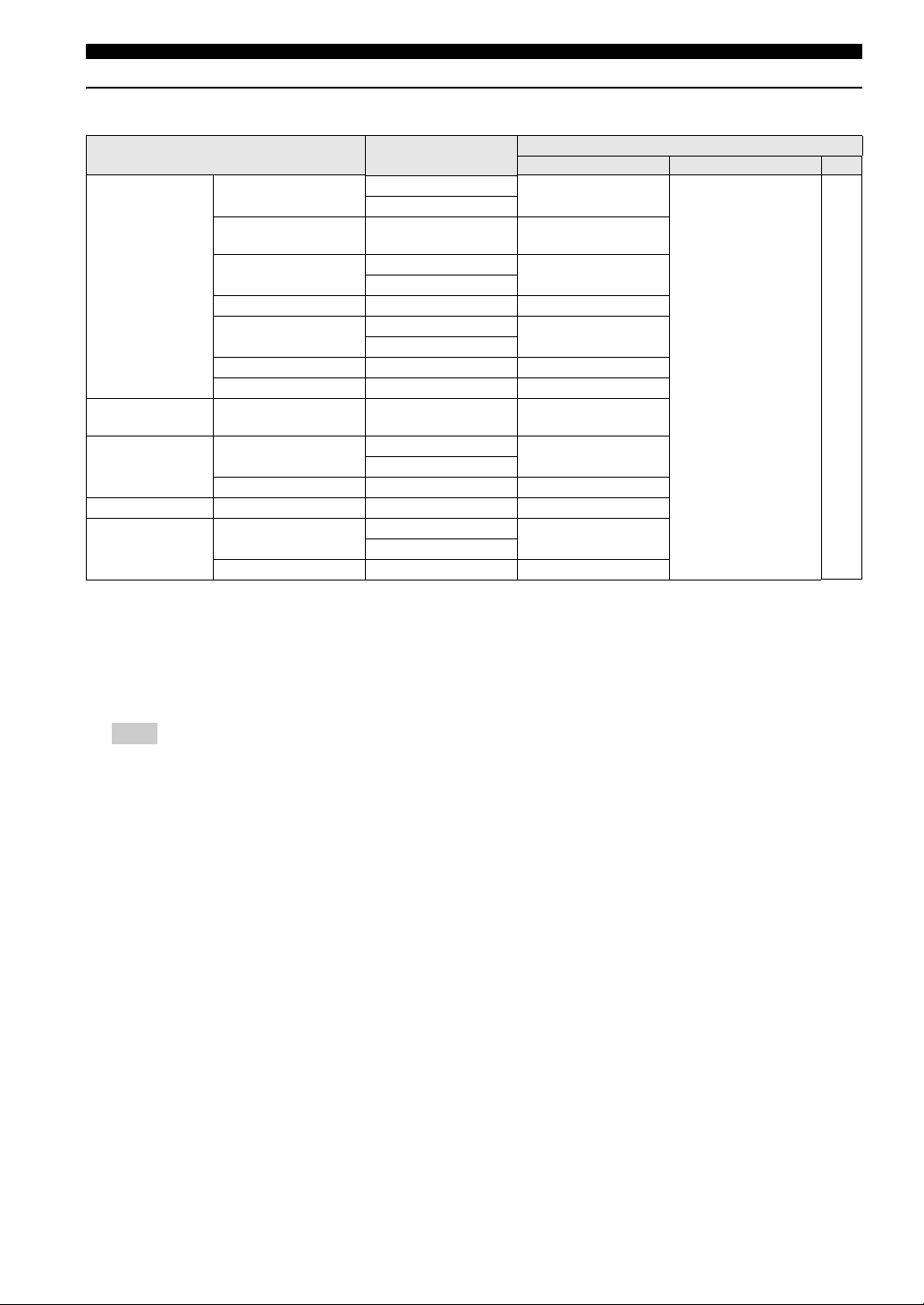
■ Menu overview
The bold items/parameters listed below are the default settings.
Setup page Menu item Setting Item/Submenu Setting item/Parameter Page
GENERAL
SETUP PAGE
AUDIO
SETUP PAGE
VIDEO
SETUP PAGE
PREFERENCE
PAGE
DISC LOCK LOCK, UNLOCK 34
PROGRAM INPUT MENU 34
OSD LANGUAGE ENGLISH, DANSK, DEUTSCH, ESPAÑOL,
SCREEN SAVER ON, OFF 35
AUTO STANDBY ON, OFF 35
DIVX(R) VOD
CODE
HDMI AUDIO OUT
SPEAKER SPEAKER VOLUME SETUP (FRONT LEFT) –6dB to +6dB (0dB)36
CD UPSAMPLING OFF, 88.2kHz (X2) 36
LIP SYNC DELAY TIME 0 MS to 200 MS 36
TV TYPE PAL, NTSC, MULTI 37
TV DISPLAY 4:3 PAN SCAN, 4:3 LETTER BOX, 16:9 37
PICTURE
SETTING
ADV PICTURE DCDI OFF, ON 38
PROGRESSIVE OFF, ON 40
COMPONENT YUV, RGB 40
AUDIO ENGLISH (for [AUDIO] and
SUBTITLE
DISC MENU
PARENTAL 1 KID SAFE, 2 G, 3 PG, 4 PG 13,
PBC ON, OFF 42
MP3/JPEG NAV WITH MENU, WITHOUT MENU 42
VR LIST ORIGINAL LIST, PLAY LIST 42
PASSWORD CHANGE 43
DIVX SUBTITLE GROUP1, GROUP2, GROUP3, GROUP4,
DEFAULT RESET 43
FRANÇAIS, ITALIANO, NEDERLANDS,
NORSK, POLSKI, PORTUGUÊS,
РУССКИЙ, SVENSKA, TÜRKÇE
®
registration code is displayed) 35
(DivX
AUTO, PCM, OFF 36
(FRONT RIGHT) –6dB to +6dB (0dB)
(SUBWOOFER) –6dB to +6dB (0dB)
STANDARD, BRIGHT, SOFT 37
PERSONAL (BRIGHTNESS) –20 to +20 (0)
PERSONAL (SHARPNESS) –7 to +7 (0)
PERSONAL (CONTRAST) –16 to +16 (0)
PERSONAL (TINT) –9 to +9 (0)
PERSONAL(COLOR) –9 to +9 (0)
GAMMA –7 to +7 (0)
CHROMA DELAY –3 to +3 (0)
WIDE SCREEN FORMAT NL STRETCH, 4:3 PILLAR BOX,
HDMI VIDEO 480P, 576P, 720P, 1080I, 1080P,
TRUE LIFE 0 to 5
DVI OUTPUT RANGE ENHANCED, STANDARD
[DISC MENU]),
OFF (for [SUBTITLE]), etc.
5 PGR, 6 R, 7 NC 17, 8 ADULT
GROUP5
OFF
AUTO
35
5
ON-SCREEN MENU
41
41
43
English
33 En
Page 36

DVD setup menu options
This setup is carried out via the TV,
enabling you to customize the DVD
receiver to suit your particular
requirements.
Notes
– To return to the previous menu, press .
– To exit from the menu, press SET UP.
– If the settings you have selected are not
appropriate, you can reset all settings to the initial
factory settings (see “Restoring to the factory
defaults” on page 43).
■ General setup menu
1 In DVD/CD mode, press SET UP.
2 Press / to select [GENERAL SETUP PAGE].
3 Press ENTER to confirm.
GENERAL SETUP PAGE
DISC LOCK
PROGRAM
OSD LANGUAGE
SCREEN SAVER
AUTO STANDBY
DIVX(R) VOD CODE
Locking/Unlocking discs for viewing
Not all discs are rated or coded by the manufacturer of the
disc. You can prevent playback of a specific disc by
locking the disc. You can lock up to 40 discs on this unit.
1 In [GENERAL SETUP PAGE], press / to
Programming disc tracks (except
®
picture CD/MP3/WMA/DivX
You can playback the contents of a disc in the order you
want by programming the tracks to be played. You can
store up to 20 tracks.
1 Press PROG on the remote control, or in [GENERAL
SETUP PAGE], press / to highlight
[PROGRAM], then press to select [INPUT
MENU].
2 Press ENTER to confirm.
PROGRAM: TRACK (01-17)
1 04
2 10
3 _ _
4 _ _
5 _ _
EXIT START NEXT
To program your favorite tracks/chapters
3 Use the numeric keypad (0-9) to enter a valid
track/chapter number.
4 Use / / / to move the cursor to the next
position.
If the track number is more than ten, press a to
open the next page and proceed with programming, or
use / / / to highlight [NEXT] on the
program menu, then press ENTER.
5 Repeat steps 3 and 4 to input another track/chapter
number.
To remove a track
6 _ _
7 _ _
8 _ _
9 _ _
10 _ _
discs)
highlight [DISC LOCK], then press .
LOCK
Select this to block playback of the current disc.
Subsequent access to a locked disc requires a six-digit
password. The default password is ‘000 000’ (see
“Changing the password” on page 43).
UNLOCK
Select this to unlock the disc and allow future
playback.
2 Press / to select a setting and press ENTER
to confirm.
34 En
6 Use / / / to move the cursor to the
track you want to remove.
7 Press ENTER to remove this track from the program
menu.
8 To exit the menu, press PROG. Or use / / /
to move the cursor to select [EXIT], then press
ENTER to confirm.
Page 37

DVD setup menu options
OSD language
This menu contains various language options for
displaying languages on the screen. For details, see “Onscreen display (OSD) language” on page 23.
Screen saver
The screen saver helps prevent your TV display from
becoming damaged.
1 In [GENERAL SETUP PAGE], press / to
highlight [SCREEN SAVER], then press .
ON
Select this if you wish to turn off the TV screen when
play is stopped or paused for more than 15 minutes.
OFF
Select this to disable the screen saver function.
2 Press / to select a setting and press ENTER
to confirm.
3 To return to the previous menu, press .
To exit the menu, press SET UP.
Turning the auto standby function on/
off
This function is used to turn on or off the auto standby
function.
1 In [GENERAL SETUP PAGE], press / to
highlight [AUTO STANDBY], then press .
ON
Select this to set the DVD receiver to the standby
mode automatically when disc playback is stopped for
more than 30 minutes or when the disc menu is
displayed for more than three hours without
performing any operation.
OFF
Select this to disable the auto standby function.
2 Press / to select a setting and press ENTER
to confirm.
DivX®VOD registration code
Yamaha provides you with the DivX®VOD (Video On
Demand) registration code that allows you to rent and
purchase videos using the DivX®VOD service. For more
information, go to www.divx.com/vod.
5
ON-SCREEN MENU
1 In [GENERAL SETUP PAGE], press / to
highlight [DIVX(R) VOD CODE], then press .
→ The registration code appears.
2 Press ENTER to exit.
3 Use the registration code to purchase or rent the
videos from DivX®VOD service at www.divx.com/
vod. Follow the instructions and download the video
onto a CD-R/RW for playback on this receiver.
Note
All the videos downloaded from DivX
be played back on this receiver.
®
VOD can only
English
35 En
Page 38

DVD setup menu options
■ Audio setup menu
1 In DVD/CD mode, press SET UP.
2 Press / to select [AUDIO SETUP PAGE].
3 Press ENTER to confirm.
AUDIO SETUP PAGE
HDMI AUDIO OUT
SPEAKER
CD UPSAMPLING
LIP SYNC
CD upsampling
This feature allows you to convert your music CD to a
higher sampling rate using sophisticated digital signal
processing for better sound quality.
Note
When the CD upsampling function is activated (or a
disc recorded at the sampling rate of 96 kHz is played
back), the music enhancer function is not available.
1 In [AUDIO SETUP PAGE], press / to
highlight [CD UPSAMPLING], then press .
OFF
Select this to disable CD-upsampling.
Setting the HDMI audio
When you connect the DVD receiver to an HDMI
compatible component via the HDMI terminal, set the
HDMI audio output to match the connected component.
For details about the relationship between the audio
format and the setting, see “HDMI audio output” on
page 16.
1 In [AUDIO SETUP PAGE], press / to
highlight [HDMI AUDIO OUT], then press .
AUTO
Select this to set the DVD receiver to the best setting
automatically based on the component you have
connected via the HDMI terminal.
PCM
Select this to output the decoded multichannel or 2channel PCM audio signals via the HDMI terminal.
OFF
Select this to turn off the HDMI audio output.
2 Press / to select a setting and press ENTER
to confirm.
Note
If the monitor/receiver connected to the DVD receiver
using HDMI does not support HDMI audio signal
input, set this setting to [OFF].
88.2 kHz (X2)
Select this to convert the sampling rate of CDs to
twice that of the original.
2 Press / to select a setting and press ENTER
to confirm.
Lip synchronization
This feature allows you to delay the sound output from the
front speakers in order to synchronize it with the video
image. This may be necessary when using certain LCD
monitors or projectors.
Choices: 0 to 200 ms
1 In [AUDIO SETUP PAGE], press / to
highlight [LIP SYNC], then press .
2 Press / to adjust the delay time (between 0 ms
and 200 ms) and press ENTER to confirm.
Speaker setup
This menu contains setup options for audio output so that
you can set your speakers to reproduce high quality
surround sound.
36 En
Page 39

DVD setup menu options
■ Video setup menu
1 In DVD/CD mode, press SET UP.
2 Press / to select [VIDEO SETUP PAGE].
3 Press ENTER to confirm.
VIDEO SETUP PAGE
TV TYPE
TV DISPLAY
PICTURE SETTING
ADV PICTURE
PROGRESSIVE
COMPONENT
TV type
This menu contains the options for selecting the color
system that matches the connected TV. For details, see
“Selecting the TV type” on page 21.
Note
When [PROGRESSIVE] is set to [ON] (see page 40),
composite video/S-video output depends on the format of
the disc.
Disc
format
NTSC PAL 576p 480i
PAL PAL 576p 575i
TV
TYPE
NTSC 480p 480i
MULTI 480p 480i
NTSC 480p 575i
MULTI 576p 575i
TV display
This menu contains the options for matching the aspect
ratio of the receiver to the connected TV. For details, see
“Setting the TV display” on page 22.
Output format
Component
video
Composite
video/S-video
Picture settings
Note
This receiver comes with three predefined sets of picture
color settings and one personal setting that you can define
yourself.
1 In [VIDEO SETUP PAGE], press / to
highlight [PICTURE SETTING], then press .
STANDARD
Select this for the standard picture setting.
BRIGHT
Select this to make the TV picture brighter.
SOFT
Select this to make the TV picture softer.
PERSONAL
Select this to personalize your picture color by
adjusting the brightness, sharpness, contrast, tint and
color (saturation).
2 Press / to select a setting and press ENTER
to confirm.
3 If you selected [PERSONAL], proceed to step 4.
→ The [PERSONAL PICTURE SETUP] menu
appears.
PERSONAL PICTURE SETUP
BRIGHTNESS
SHARPNESS
CONTRAST
TINT
COLOR
4 Press / to highlight one of the following
options.
BRIGHTNESS
Increase the value to brighten the picture or vice versa.
You can adjust the value from -20 to +20. Zero (0) is
the average setting value.
0
0
0
0
0
5
ON-SCREEN MENU
SHARPNESS
Increase the value to sharpen the picture or vice versa.
You can adjust the value from -7 to +7. Zero (0) is the
average setting value.
37 En
English
Page 40

DVD setup menu options
CONTRAST
Increase the value to sharpen the picture contrast or
vice versa. You can adjust the value from -16 to +16.
Zero (0) is the average contrast.
TINT
Increase or decrease the value to change the color
phase of the picture. You can adjust the value from -9
to +9. Zero (0) is the average setting value.
COLOR
Increase the value to enhance the color in your picture
or vice versa. You can adjust the value from -9 to +9.
Zero (0) is the average color setting value.
5 Press / to adjust the setting that best suits your
personal preference.
6 Repeat steps 4 and 5 to adjust other color features if
desired.
7 Press ENTER to confirm.
Note
All picture settings are not available for HDMI output.
Adjusting the advanced picture
settings
You can fine-tune the following video parameters.
We recommend setting the aspect ratio on your TV if the
function is available.
[DCDI]
DCDi (Directional Correction Deinterlacing) computes
and tracks the angle of the screen edge to fill in the
missing pixel on the TV screen. DCDi optimizes the
image quality significantly, especially during the slow
motion playback. This function is available for
progressive scan output only.
1 Select [ADV PICTURE] in [VIDEO SETUP PAGE].
2 Press / to highlight [DCDI], then press .
OFF
Select this to disable the DCDi function.
ON
Select this to enable the DCDi function.
3 Press / to select a setting and press ENTER
to confirm.
[GAMMA]
Adjust the intensity of the picture non-linearly. A positive
value enables you to bring out low level detail in dark
scenes, while a negative value emphasizes contrast. This
function is not available for HDMI output.
You can adjust the value from -7 to +7.
1 Select [ADV PICTURE] in [VIDEO SETUP PAGE].
2 Press / to highlight [GAMMA], then press
.
3 Press / to select a setting and press ENTER to
confirm.
38 En
Page 41

DVD setup menu options
[CHROMA DELAY]
The chroma (color) and luminance (brightness) signals are
not synchronized. You can adjust the advance delay of the
chroma signal to yield a perfectly clear picture. This
function is not available for HDMI output.
You can adjust the value from -3 to +3.
1 Select [ADV PICTURE] in [VIDEO SETUP PAGE].
2 Press / to highlight [CHROMA DELAY],
then press .
3 Press / to select a setting and press ENTER to
confirm.
[WIDE SCREEN FORMAT]
Set the aspect ratio of the projected images on the screen.
This function is only available for progressive scan and
HDMI output.
1 Select [ADV PICTURE] in [VIDEO SETUP PAGE].
2 Press / to highlight [WIDE SCREEN
FORMAT], then press .
NL STRETCH
Select this to display a 4:3 image on the 16:9 screen
with non-linear stretching (center position of screen is
stretched less than the sides).
4:3 PILLAR BOX
Select this to display a 4:3 image on the 16:9 screen
without stretching.
OFF
No aspect ratio adjustment is made when this option is
selected.
3 Press / to select a setting and press ENTER
to confirm.
[HDMI VIDEO]
Set the resolution depending on the monitor you are using.
This function is only available when you connect the
DVD receiver to an HDMI compatible component via the
HDMI terminal.
1 Select [ADV PICTURE] in [VIDEO SETUP PAGE].
2 Press / to highlight [HDMI VIDEO], then
press .
480P
480 progressive-scan video
576P
576 progressive-scan video
720P
720 progressive-scan video
1080I
1080 interlace video
1080P
1080 progressive-scan video
AUTO
The resolution is automatically selected to match the
component you are using.
3 Press / to select a setting and press ENTER
to confirm.
Notes
– For settings other than [AUTO], HDMI video
signals may not be output properly if a resolution
output setting is not supported by the HDMI
component you are using. In this case, follow the
steps below to change [HDMI VIDEO] to [480P].
– If a disc is inserted, press to eject the disc.
– Press .
– Press AUDIO.
Do not perform this operation while playing back a
disc on the DVD receiver.
5
ON-SCREEN MENU
39 En
English
Page 42

DVD setup menu options
[TRUE LIFE]
Adjust the intensity of the picture details. A positive value
enables you to reproduce the minute signals of video
sources.
This function is only available for progressive scan (using
the component video jacks) and HDMI output.
You can adjust the value from 0 to 5.
1 Select [ADV PICTURE] in [VIDEO SETUP PAGE].
2 Press / to highlight [TRUE LIFE], then press
.
3 Press / to select a setting and press ENTER to
confirm.
[DVI OUTPUT RANGE]
Set the DVI output range to match the connected
component. This function is only available when you
connect the DVD receiver to an DVI-D-compatible
component via the HDMI terminal.
1 Select [ADV PICTURE] in [VIDEO SETUP PAGE].
2 Press / to highlight [DVI OUTPUT
RANGE], then press .
ENHANCED
Select this if black and white in the image is not
distinct.
1 In [VIDEO SETUP PAGE], press / to
highlight [PROGRESSIVE], then press .
OFF
Select this to disable progressive scan function.
ON
Select this to enable progressive scan function.
2 Press / to select a setting and press ENTER
to confirm.
→ Follow the instructions shown on the TV to
confirm the selection (if any).
–
If a blank/distorted TV screen appears, wait for 15
seconds for auto recovery to activate.
Note
If you are changing the setting to OFF by using the remote
control, follow the procedure below.
1 If a disc is inserted, press to eject the disc.
2 Press , then press ANGLE.
Component
(Europe and Russia models only)
This setting allows you to toggle the output of the video
signal between RGB (on SCART) and Y Pb Pr (YUV).
STANDARD
Select this if you cannot see the correct image when
you select [ENHANCED].
3 Press / to select a setting and press ENTER
to confirm.
Progressive function
The progressive scan display present 60 complete frames
per seconds, rather than 30 frames per second of interlaced
scanning (ordinary normal TV system). With nearly
double the number of lines, progressive scan offers higher
picture resolution and eliminates bothersome motion
artifacts those jagged edge on moving objects.
Note
Before enabling the progressive scan function, you must
ensure:
1 Turn on your TV progressive scan function (refer
to your TV owner’s manual).
2 You have connected the DVD receiver to your TV
using Y P
page 14).
B PR (see “Connecting a TV” on
40 En
Page 43

■ Preference setup menu
1 Press s twice to stop playback (if necessary), then
press SET UP.
2 Press / to select [PREFERENCE PAGE].
3 Press ENTER to confirm.
PREFERENCE PAGE
AUDIO
SUBTITLE
DISC MENU
PARENTAL
PBC
MP3/JPEG NAV
VR LIST
PASSWORD
Audio, subtitle and disc menus
These menus contain various language options for the
audio, subtitle and disc menus recorded on the DVD. For
details, see “Audio, Subtitle and Disc menu languages” on
page 23.
DVD setup menu options
Restricting playback with parental
control
Some DVDs may have a parental level assigned to the
complete disc or to certain scenes on the disc. This feature
lets you set a playback limitation level. The rating levels
are from 1 to 8 and are country dependent. You can
prohibit the playing of certain discs that are not suitable
for your children, or play alternative scenes for certain
discs.
1 In [PREFERENCE PAGE], press / to
highlight [PARENTAL], then press .
PREFERENCE PAGE
AUDIO 1 KID SAFE
SUBTITLE 2 G
DISC MENU 3 PG
PARENTAL 4 PG 13
PBC 5 PGR
MP3/JPEG NAV 6 R
VR LIST 7 NC 17
PASSWORD 8 ADULT
2 Press / to highlight a rating level for the disc
inserted and press ENTER.
5
ON-SCREEN MENU
3 Use the numeric keypad (0-9) to enter the six-digit
password (see “Changing the password” on page 43).
→ DVDs that are rated above the level you select
will not play unless you enter the six-digit password.
English
41 En
Page 44

DVD setup menu options
Rating explanation
1 KID SAFE
2 G
General audience; recommended as acceptable for
viewers of all ages.
3 PG
Parental guidance suggested.
4 PG 13
Material is unsuitable for children under age 13.
5 PGR
6 R
Parental guidance - restricted; recommended that
parents restrict children under 17 from viewing, or
allow to view only when supervised by a parent or
adult guardian.
7 NC 17
Material is unsuitable for children under age 17.
8 ADULT
Mature material; should be viewed only by adults due
to the inclusion of graphic sexual material, violence or
language.
Notes
– VCD, SVCD, CD have no level indication, so the
parental control function has no effect with these
types of discs. This also applies to most illegal
DVDs.
– Some DVDs are not encoded with a rating though
the movie rating may be printed on the disc cover.
The rating level feature does not prohibit play of
such discs.
MP3/JPEG navigator
MP3/JPEG navigator can be set only if the disc was
recorded with a menu. It allows you to select different
display menus for easy navigation.
1 In [PREFERENCE PAGE], press / to
highlight [MP3/JPEG NAV], then press .
WITH MENU
Select this to display only the folder menu of the MP3/
Picture CD.
WITHOUT MENU
Select this to display all the files contained in the
MP3/Picture CD.
2 Press / to select a setting, then press ENTER
to confirm.
Playback VR format discs
There are two ways to play back a VR (Video Recording)
format discs: ORIGINAL LIST and PLAY LIST. This
feature is not available with non-VR format discs.
1 In [PREFERENCE PAGE], press / to
highlight [VR LIST], then press . The following
settings appear:
ORIGINAL LIST
Select this to play the originally recorded titles on the
disc.
PLAY LIST
Select this to play the edited version of the disc. This
feature is only available when a play list has been
created.
PBC
You can set PBC to ON or OFF. This feature is available
only on Video CD 2.0 with the playback control (PBC)
feature. For details, see “Playback control (PBC)” on
page 28.
42 En
2 Press / to highlight a setting, then press
ENTER to confirm.
3 Press SET UP to close the setup menu.
4 Press h. The setting you selected begins to play.
Page 45

DVD setup menu options
Changing the password
The same password is used for both parental control and
disc lock. Enter your six-digit password to play a
prohibited disc or if prompted for a password. The default
password is ‘000 000’.
1 In [PREFERENCE PAGE], press / to
highlight [PASSWORD], then press to select
[CHANGE].
PREFERENCE PAGE
AUDIO
SUBTITLE
DISC MENU
PARENTAL
PBC
MP3/JPEG NAV
VR LIST
PASSWORD CHANGE
2 Press ENTER to enter the ‘Password Change Page’.
OLD PASSWORD
NEW PASSWORD
CONFIRM PWD
OK
Changing the DivX subtitle
If the video downloaded from DivX®VOD has subtitles,
you can select its character code.
1 In [PREFERENCE PAGE], press / to
highlight [DIVX SUBTITLE], then press to select
[GROUP1].
2 Press ENTER to confirm.
Notes
– Some discs cannot be played depending on disc
characteristics or recording conditions.
– Some external subtitle files may be displayed
incorrectly or not at all.
– For external subtitle files, the following subtitle
format filename extensions are supported (note that
these files are not shown within the disc navigation
menu): .srt, .sub, .ssa, .smi
– The filename of the movie file has to be repeated at
the beginning of the filename for the external
subtitle file.
– The number of external subtitle files that can be
switched for the same movie file is limited to a
maximum of ten.
Restoring to the factory defaults
Setting the DEFAULT function will reset all options and
your personal settings to the factory defaults, except your
password for Parental Control and Disc Lock.
5
ON-SCREEN MENU
3 Use the numeric keypad (0-9) to enter your old six-
digit password.
–
When doing this for the first time, enter ‘000 000’.
–
If you forget your old six-digit password, enter ‘000
000’.
4 Enter the new six-digit password.
5 Enter the new six-digit password a second time to
confirm.
6 Press ENTER to confirm.
→ The new six-digit password is now valid.
1 In [PREFERENCE PAGE], press / to
highlight [DEFAULT], then press to select
[RESET].
2 Press ENTER to confirm.
→ All settings are reset to the factory defaults.
English
43 En
Page 46

OTHER FEATURES
Tuner operations
Note
Make sure the FM and AM antennas are connected to this
receiver.
Numeric
keypad (0-9)
dPRESETu
(b / a)
STANDBY/ON
ON SCREEN
SET UP
SUBTITLE
DIMMER
NIGHT
BASS TREBLE
FREQ/TEXT
PROG
REPEAT
PTY SEEK
MODE START
SHUFFLE
A-B
PRESET PRESET
ENTER
AREA
DIRECT
MODE
ENHANCER
MUTE
SURROUND
DVD/CD
TUNER
AUX
ANGLE ZOOM AUDIO
EJECT
USB
SLEEP
MENU
TOP MENU
PROG
/RETURN
TUNER
■ Tuning radio stations
1 Press TUNER to select “TUNER/FM” or “TUNER/
AM”.
2 Press / briefly on the remote control.
→ “SEARCH” appears.
→ The next radio station is tuned automatically.
3 Repeat step 2 (if necessary) until you find the desired
radio station.
4 To tune weak stations, press / briefly and
repeatedly until the optimal reception is found.
■ Presetting radio stations
You can store up to 30 preset radio stations (including
both FM and AM stations) in the receiver's memory.
Note
The receiver will exit presetting mode if no button is
pressed within 20 seconds.
Automatic presetting
You can start automatic presetting by pressing a selected
preset number.
1 Press TUNER to select “TUNER/FM” or “TUNER/
AM”.
2 Press b / a or use the numeric keypad (0-9)
to select a preset number to begin.
3 Press and hold PROG until “AUTO” appears.
→ If a radio station is stored in one of the earlier
presets, the same radio station will not store under
another preset number.
→ If no preset number is selected, automatic preset
will begin from preset (1) and all former presets will
be overridden.
Manual presetting
You can choose to store only your favourite radio stations.
1 Tune the desired radio station (see “Tuning radio
stations” on page 44).
2 Press PROG.
3 Press b / a to select a preset number.
4 Press PROG again to store.
Note
(Europe and Russia models only)
While receiving an FM station, the name of the station you
selected appears in the system display panel.
44 En
Page 47

Selecting a preset radio station
ENTER
REPEAT
ON SCREEN
MENU
SET UP
TOP MENU
/RETURN
FREQ/TEXT
MODE START
PRESET PRESET
PROG
A-B
SHUFFLE
PTY SEEK
Press b / a or use the numeric keypad (0-9) to
select a preset number.
→ The preset number, then radio frequency appears.
Deleting a preset radio station
Press and hold s on the front panel until “Preset Deleted”
starts scrolling.
→ The current preset radio station is deleted.
Setting frequency step
(except Europe and Russia models)
The inter-station frequency spacing differs depending on
the areas. Set the frequency step according to the
frequency spacing in your area.
Choices:AM9kHz/FM50kHz, AM10kHZ/FM100kHz
Default setting: AM9kHz/FM50kHz
To change the AM band to 10kHz and the
FM band to 100kHz
1 Unplug the AC power cord from the DVD receiver
and wait at least one minute.
Tuner operations
■ Receiving Radio Data System stations (Europe and Russia models only)
The Radio Data System is a data transmission system for
FM stations used mainly in the U.K. and Europe. The
DVD receiver can receive Radio Data System data such as
PS (program service) and PTY (program type) when
receiving Radio Data System broadcasting stations.
To select stations by program type
(genre)
You can tune Radio Data System stations by selecting a
program type (genre) from 31 options. Once you select a
program type, the DVD receiver automatically searches
for Radio Data System stations broadcasting
corresponding program type.
FREQ/TEXT
PTY SEEK
MODE
PTY SEEK
START
dPRESETu
6
OTHER FEATURES
2 While pressing and holding INPUT and a on the
front panel, plug the AC power cord to the DVD
receiver.
Note
Repeat the above steps 1 to 2 to change AM band to 9kHz
and FM band to 50kHz.
1 While receiving an FM, press FREQ/TEXT.
2 Press FREQ/TEXT to select the PTY mode.
3 Press PTY SEEK MODE.
4 Press PRESET d/u to select the program type.
The PTY program type flashes in the display panel.
Program type Descriptions
NEWS News
AFFAIRS Current Affairs
INFO Information
SPORT Sports
EDUCATE Education
DRAMA Drama
CULTURE Cultures
SCIENCE Science
VARIED Varied Speech
POP M Pop Music
English
ROCK M Rock Music
EASY M Easy Listening
LIGHT M Light Classics
45 En
Page 48

Tuner operations
Program type Descriptions
CLASSICS Serious Classics
OTHER M Other Music
WEATHER Weather & Meteorology
FINANCE Finance
CHILDREN Children’s Program
SOCIAL Social Affairs
RELIGION Religion
PHONE IN Phone In
TRAVEL Travel & Touring
LEISURE Leisure & Hobby
JAZZ Jazz Music
COUNTRY Country Music
NATION M National Music
OLDIES Oldies Music
FOLK M Folk Music
DOCUMENT Documentary
Notes
– The available Radio Data System information
types vary depending on the station.
– If the signal transmission of the Radio Data System
station is too weak, the DVD receiver may not be
able to receive Radio Data System information
completely.
TEST Alarm Test
ALARM Alarm
5 Press PTY SEEK START.
The DVD receiver starts searching for the
corresponding Radio Data System stations. The DVD
receiver stops searching when the selected program
type is found. The program name shows up on the
display panel.
To cancel PTY SEEK
Press PTY SEEK START again.
To switch the information display of
Radio Data System
While receiving Radio Data System, press FREQ/TEXT.
Each time you press the button, the information display
changes as follows:
PROGRAM SERVICE
PROGRAM TYPE
Information type
• PROGRAM SERVICE (PS)
Displays the station name.
• PROGRAM TYPE (PTY)
Displays the program type (genre).
46 En
Page 49

Sound controls
Note
For proper surround sound, make sure the speakers and
subwoofer are connected to this receiver (see “Connecting the
subwoofer” on page 12).
STANDBY/ON
TREBLE/BASS
FREQ/TEXT
PRESET PRESET
ON SCREEN
SET UP
AREA
MODE
SURROUND
SUBTITLE
BASS TREBLE
REPEAT
A-B
AREA
MODE
SURROUND
AUX
ANGLE ZOOM AUDIO
DIMMER
PTY SEEK
MODE START
ENTER
DIRECT
ENHANCER
DVD/CD
TUNER
NIGHT
PROG
SHUFFLE
EJECT
SLEEP
MENU
TOP MENU
/RETURN
MUTE
USB
VOLUME (+/–)
ENHANCER
■ Using the Virtual Surround function
Turning the Virtual Surround function
on/off
This function allows you to convert 2.1 channel sound to
virtual 5.1 channel surround sound.
Press SURROUND on the remote control to enable the
Virtual Surround function.
→ “SURR ON” appears.
To disable the Virtual Surround function
Press SURROUND again.
→ “SURR OFF” appears.
Changing the Virtual Surround area
This function is used to change the Virtual Surround area
setting.
With Virtual Surround activated, press AREA on the
remote control to select the Virtual Surround area.
NARROW
Select this to sharpen the sound field. The optimal
listening area will be limited.
WIDE
Select this to widen the optimal listening area. The
sound field will be less focused.
Changing the Virtual Surround mode
This function is used to change the Virtual Surround mode
setting.
With Virtual Surround activated, press MODE on the
remote control to select the Virtual Surround mode.
MUSIC
Select this for music content.
MOVIE
Select this for movie content.
Adjusting the sound balance
This function adjusts the sound balance according to your
listening position to optimize the Virtual Surround effect.
1 With Virtual Surround activated, press and hold
SURROUND on the remote control.
→ “POS CENT” appears.
2 Within three seconds, press VOLUME (+/–) to adjust
the sound balance (POS L6, POS L5, POS L4, POS
L3, POS L2, POS L1, POS CENT, POS R1, POS R2,
POS R3, POS R4, POS R5 or POS R6).
→ If the volume control is not used within three
seconds, it will resume its normal volume control
function.
Note
The selected sound balance automatically returns to “POS
CENT” when you turn off the DVD receiver.
■ Setting music enhancer
This function enhances your listening experience by
regenerating the missing harmonics in a compression
artifact.
Press ENHANCER on the remote control to enable the
music enhancer.
→ “ENH ON” appears.
To disable the music enhancer function
Press ENHANCER again.
→ “ENH OFF” appears.
Notes
– The night listening mode and the music enhancer
cannot be activated at the same time.
– When the CD upsampling function is activated (or
a disc recorded at the sampling rate of 96 kHz is
played back), the music enhancer function is not
available.
6
OTHER FEATURES
English
47 En
Page 50

Sound controls
■ Night listening mode
When night listening mode is activated, high volume
output is softened and low volume output raised to an
audible level. This is useful for watching your favorite
action movie without disturbing others at night.
– Press NIGHT on the remote control to activate the
night listening mode.
→ Playback continues at a more even volume and
“
NIGHT ON” appears in the display panel.
– To restore the volume, press NIGHT again.
→ Playback continues with the full dynamic range of
surround sound, and “
display panel.
Notes
– The night listening mode and the music enhancer
cannot be activated at the same time.
– When the CD upsampling function is activated (or
a disc recorded at the sampling rate of 96 kHz is
played back), night listening mode is not available.
NIGHT OFF” appears in the
■ Adjusting the treble/bass level
The TREBLE (high tone) and BASS (low tone) features
enable you to define the sound-processor settings.
1 Press TREBLE or BASS on the remote control.
2 Within three seconds, press VOLUME (+/–) to adjust
the treble or bass level (-6dB to +6dB, in 1dB
increments).
→ If the volume control is not used within three
seconds, it will resume its normal volume control
function.
■ Adjusting the volume level
Use the VOLUME control (or press VOLUME (+/–) on
the remote control) to increase or decrease the volume
level.
→ “VOL MIN” is the minimum volume level and “VO L
” is the maximum volume level.
MAX
To mute the volume temporarily
Press MUTE on the remote control.
–
Playback continues without sound and “MUTE” appears.
To restore the volume, press MUTE again or increase/
–
decrease the volume level.
48 En
Page 51

Other functions
■ Switching to standby mode
Press STANDBY/ON on the front panel or STANDBY/
ON ( ) on the remote control.
→ The display screen goes blank.
■ Dimming the display screen
In any active mode, press DIMMER on the remote control
to select the desired brightness:
DIM 1: 70% brightness
DIM 2: 40% brightness
DIM OFF: normal brightness
■ Setting the sleep timer
The sleep timer switches the receiver to Eco Power
standby mode automatically at the preset time.
1 Press SLEEP on the remote control until “SLEEP XX”
appears in the display panel (
OFF).
2 To select the next sleep timer value, continue pressing
SLEEP while in sleep timer mode until the desired
turn-off time is displayed.
XX: 15, 30, 45, 60 or
→ “SLEEP” appears in the display panel, except
when “
SLEEP OFF” is selected.
→ Before the receiver switches to Eco Power
standby mode, a countdown of 10 seconds is
displayed.
“
SLEEP 10” → “SLEEP 9”.... →
“SLEEP 2” → “SLEEP 1”
To cancel the sleep timer
Press SLEEP until “
SLEEP OFF” appears.
■ Recording on an external AV component
6
OTHER FEATURES
1 Connect the external recording component to LINE
OUT (see “Connecting external AV components” on
page 18).
2 Select the source to record from this DVD receiver
(DVD/CD, TUNER, AUX or USB) and start playback
(if necessary).
3 Start recording on the external recording device.
Note
Refer to the owner’s manual of the connected
component for details.
English
49 En
Page 52

ADDITIONAL INFORMATION
Troubleshooting
If there is any problem with your Home Theater Sound System, check the following items. If you cannot solve your
problem with the following remedies or if your problem is not listed below, turn off and unplug the Home Theater Sound
System, then consult the nearest authorized Yamaha dealer or service center.
Problem Solution
No power Check if the AC power cord is properly connected.
Press STANDBY/ON on the front of the receiver to turn on the power.
No picture Refer to your TV’s manual for correct Video In channel selection. Change
Completely distorted picture or
black/white picture
The aspect ratio of the screen cannot be changed
even though you have set the TV display
No sound or distorted sound Adjust the volume.
No sound or picture Check that the RGB/SCART cable is connected to the correct device (see
Sound is too low on one side Check if all cables are properly connected.
Cannot activate some features such as Angles,
Subtitles, or multi-language Audio
DVD videos cannot be copied with the VCR Most commercially available DVD’s include copy protect features. You
The disc is ejected without an operation Make sure that you use a disc supported by the DVD receiver.
Not able to select some items in the setup/system
menu
The DVD receiver does not start playback Insert a readable disc with the playback side facing down. The DVD-R/
the TV channel until you see the DVD screen.
Press DVD/CD on the remote control in order to switch to DVD/CD mode.
If this happens when you are changing the setting of the ‘TV TYPE’, wait
for 15 seconds for auto recovery (see page 21).
If this happens when you are turning on the progressive scan feature, wait
for 15 seconds for auto recovery (see page 40).
Check the video connection.
Sometimes a small amount of picture distortion may appear.
This is not a malfunction.
Clean a disc.
The aspect ratio is fixed on the DVD disc.
Depending on the TV, it may not be possible to change the aspect ratio.
Check if the system cable is properly connected.
Check if all speaker cables are properly connected.
Make sure that the audio cables are connected and press the Input selection
buttons to select the correct input source (AUX, for example) to choose the
equipment that you want to hear through the DVD receiver.
Check if the AC power cord of the subwoofer is properly connected.
Make sure that you use a disc supported by the DVD Player.
“Connecting a TV” on page 14).
The features may not be available on the DVD.
Changing the language for the sound or subtitle is prohibited on the DVD.
cannot make a copy of these DVD’s.
Press s twice before selecting the setup/system menu.
Depending on the disc availability, some menu items cannot be selected.
DVD+R/DVD-RW/DVD+RW/CD-R/CD-RW/DVD-RW (VR format)
must be finalized.
Check the disc type, color system (PAL or NTSC) and region code.
Check for any scratches or smudges on the disc.
Press SET UP to turn off the setup menu screen.
You may need to enter the password in order to change the parental control
rating level or to unlock the disc for playback.
Moisture has condensed inside the player. Remove the disc and leave the
receiver turned on for about an hour.
50 En
Page 53

Troubleshooting
Problem Solution
Sound played on the DVD receiver cannot be
recorded with an external recorder
Sounds played on the AV equipment connected to
the DVD receiver cannot be recorded with
external recording equipment
The volume does not increase or sounds are
distorted
There is no sound from the subwoofer Make sure the subwoofer is connected correctly.
“SPEAKER ERR” appears in the display panel Unplug the subwoofer, then make sure the front speakers are connected
Radio reception is poor If the signal is too weak, adjust the antenna or connect an external antenna for
The remote control does not function properly Select the source (DVD/CD or TUNER, for example) before pressing the
®
Unable to play DivX
The DVD receiver does not work Disconnect the power cord from the power outlet for a few minutes. Reconnect
The USB device cannot be recognized Check that the USB device is connected correctly.
movies Check that the DivX® file was encoded in ‘Home Theater’ mode with a DivX®
Use proper audio sources.
Connect those equipment to the DVD receiver with analog connections.
Turn on the power of the component connected to the DVD receiver.
Adjust the volume level in the setup menu.
Press SURROUND button to select a correct surround sound setting.
Make sure the source you are playing is recorded or broadcast in surround
sound (DTS, Dolby Digital, etc.).
correctly.
Set the DVD receiver to the standby mode, then disconnect the power cord.
Wait for about 30 seconds, then reconnect the power cord and turn on the DVD
receiver.
better reception.
Increase the distance between the receiver and your TV or VCR.
Tune in to the correct frequency.
Place the antenna farther away from any equipment that may be causing the
noise.
function button (h, b / a).
Reduce the distance between the remote control and the receiver.
Replace the batteries with new ones.
Point the remote control directly toward the remote control sensor.
Check that the batteries are loaded correctly.
5.x encoder.
the power cord and try to operate again as usual.
Some devices may not work even if they are USB mass storage class devices.
Set the DVD receiver to the standby mode, and then turn it on again.
Disconnect the device when the DVD receiver is in the standby mode, then
connect it again and turn on the DVD receiver.
Connect the AC adapter if the adapter is supplied with the device.
If a message saying that the device is not supported appears on the TV screen,
check whether the device is supported by the DVD receiver (see “Supported
USB devices” on page 31).
If a message saying that the device is not supported (because USB current
protection is active) appears on the TV screen, the device is not playable with
the DVD receiver (see page 31).
7
ADDITIONAL INFORMATION
English
51 En
Page 54

Troubleshooting
No picture is displayed when you make HDMI
connections (using the HDMI terminals)
A disc cannot be inserted into the DVD receiver Turn on the DVD receiver and insert the disc after “NO DISC” appears on the
Follow the steps below to change [HDMI VIDEO] to [480P].
1. Press on the front panel or press and hold s on the remote control to
eject the disc.
2. Press on the remote control.
3. Press AUDIO on the remote control.
display panel.
Wait for a while and insert the disc after “NO DISC” appears on the display
panel.
Eject the disc from the DVD receiver, and then insert the disc you want to play
back after “NO DISC” appears on the display panel.
Press or p , or remove the disc from the disc loading slot fully and then
insert it once again.
52 En
Page 55

Glossary
AAC (Advanced Audio Coding)
An audio compression scheme defined as part of the
MPEG-2/MPEG-4 standard. AAC supports up to 48
channels and generally achieves better sound quality
than MP3 at the same bit rate.
Analog
Sound that has not been turned into numbers.
Analog sound varies, while digital sound has specific
numerical values. These terminals send audio through
two channels, the left and right.
Aspect ratio
The ratio of vertical and horizontal sizes of a displayed
image. The horizontal vs. vertical ratio of conventional
TVs. is 4:3, and that of wide-screens is 16:9.
Bit
Short for binary digit. Represents the smallest unit of
information manipulated on a computer. In audio
systems, the bit size determines resolution to digitize
analog signals.
The larger the bit size, the larger the dynamic range (the
ratio of maximum and minimum frequency level) and
the finer the sounds. Generally, an audio CD is 16 bit
and DVD audio is 24 bit.
Bit rate
The amount of data used to hold a given length of
music; measured in kilobits per second, or kbps. Also,
the speed at which you record. Generally, the higher the
bit rate, or recording speed, the better the sound quality.
However, higher bit rates use more space on a disc.
Component Video
Terminals for inputting or outputting a component video
signal.Component video signal consists of three lines,
the luminance signal (Y) and two color difference
signals (P
quality video.
Disc menu
A screen display prepared for allowing selection of
images, sounds, subtitles, multi-angles, etc. recorded on
a DVD.
DivX
DivX® is a video compression technology developed by
®
DivX
sizes small enough to be transported over the Internet
without reducing the original video quality. You need
DivX codec software to play back DivX movies or
convert data to the DivX format.
, PR/CR), which enable to provide high-
B/CB
Networks, Inc. It compresses digital video data to
Dolby Digital
Digital surround sound system which is developed by
Dolby Laboratories provides completely independent
multi-channel audio. With 3 front channels (left, center,
and right) and 2 surround stereo channels, Dolby Digital
provides five full-range audio channels. With an
additional channel especially for bass effects (called
LFE, or low frequency effect), the system has a total of
5.1-channels (LFE is counted as 0.1 channel). By using
2-channel stereo for the surround speakers, more
accurate moving sound effects and surround sound
environment are possible than with Dolby Surround.
Dolby Surround Pro Logic II
It is an improved matrix decoding technology that
provides better spatiality and directionality on Dolby
Surround programme material; provides a convincing
three-dimensional soundfield on conventional stereo
music recordings; and is ideally suited to bring the
surround experience to automotive sound. While
conventional surround programming is fully compatible
with Dolby Surround Pro Logic II decoders,
soundtracks will be able to be encoded specifically to
take full advantage of Pro Logic II playback, including
separate left and right surround channels. (Such material
is also compatible with conventional Pro Logic
decoders).
DTS (Digital Theater Systems)
Digital surround sound system developed by Digital
Theater Systems, Inc., which provides 5.1 channel audio
(max). With an abundance of audio data, it is able to
provide authentic-sounding effects.
HDMI
HDMI (High-Definition Multimedia Interface) is the
first industry-supported, uncompressed, all-digital
audio/video interface. Providing an interface between
any source (such as a set-top box or AV receiver) and
an audio/video monitor (such as a digital television),
HDMI supports standard, enhanced or high-definition
video as well as multi-channel digital audio using a
single cable. HDMI transmits all ATSC (Advanced
Television Systems Committee) HDTV standards and
supports 8-channel digital audio, with bandwidth to
spare to accommodate future enhancements and
requirements.
When used in combination with HDCP (Highbandwidth Digital Content Protection), HDMI
provides a secure audio/video interface that meets the
security requirements of content providers and system
operators.
For further information on HDMI, visit the HDMI
website at “www.hdmi.org/”.
Interlace
The most common type of scanning used in televisions.
It divides a screen into even and odd numbered fields for
scanning, and then builds an image by combining them
7
ADDITIONAL INFORMATION
English
53 En
Page 56

Glossary
into one image (frame).
JPEG (Joint Photographic Experts Group)
A standardized image compression system proposed by
the Joint Photographic Experts Group. It can reduce
image data sizes to 1 to 10% of their original sizes, and
works on digital photographs effectively.
MP3 (MPEG Audio Layer-3)
An audio file compression technology. It can reduce
audio data sizes to about 10% of their original sizes
while maintaining CD-level audio quality.
MPEG (Moving Pictures Experts Group)
International standard for digital video and audio
compression generated by ISO (International
Organization for Standardization) and IEC
(International Electrotechnical Commission).
Includes MPEG-1, MPEG-2, and MPEG-4. MPEG-1
offers VHS level video quality and is often used on
video CDs. MPEG-2 offers S-VHS level video quality
and is often used on DVDs.
Parental control
Limits Disc play according to the age of the users or the
limitation level in each country. The limitation varies
from disc to disc; when it is activated, playback will be
prohibited if the software’s level is higher than the userset level.
Playback control (PBC)
An on-screen menu recorded on a Video CD or SVCD
that enables interactive playback and searching.
Progressive Scan
A method of displaying all scanning lines in a frame at
once, reducing flicker noticeable on a larger screen and
creating a sharp and smooth image.
Region code
Many DVD discs include a region code so that the
copyright owner can control DVD software distribution
only to regions where they are ready to distribute. There
are six regions codes, which restrict a DVD player to
playing a DVD disc with the same region code.
S-video
A terminal for inputting or outputting an S-video signal.
S-video signal consists of two lines, the luminance
signal (Y) and color signal (C), which enable to provide
high-quality video during playback or recording.
Surround
A receiver for creating realistic three-dimensional sound
fields full of realism by arranging multiple speakers
around the listener.
VR format (Video Recording format)
A DVD video recording format, which allows editing
DVD video data recorded onto a disc. You need a VR
format compatible player for playback.
54 En
Page 57

Specifications
DVD RECEIVER (DVR-1000)
TUNER SECTION
FM Tuning Range 87.50 to 108.00 MHz
AM Tuning Range
- Europe, Russia, Australia and Korea models
- Taiwan and Asia models 531 to 1602 kHz/530 to 1700 kHz
DISC SECTION
Laser Type Semiconductor
Disc Diameter 12 cm
Video Decoding MPEG-1 /MPEG-2/DivX 3.11, 4.x & 5.x/
Video DAC 12 bits/108 MHz
Signal System PAL/NTSC
Video Format 4:3/16:9
Composite Video Output 1.0 Vp-p, 75 ohm
S-video Output Y - 1.0 Vp-p, 75 ohm
RGB (SCART) Output 0.7 Vp-p, 75 ohm
Component Video Output Y - 1.0 Vp-p, 75 ohm
Audio DAC 24 bits/192 kHz
Frequency Response 4 Hz – 20 kHz (44.1 kHz)
Audio S/N 100 dB
Distortion 0.0035%
Dynamic Range 90 dB
AUDIO FORMAT
Digital Dolby Digital/DTS/MPEG Compressed Digital
PCM 16, 20, 24 bits
MP3 (ISO 9660) 24, 32, 56, 64, 96, 128, 256 kbps
WMA 32 to 192 kbps, mono, stereo
AAC
Full decoding of Dolby Digital and DTS multi-channel sound
Dolby Surround Compatible Downmix from Dolby Digital
multi-channel sound
GENERAL
Power Supply
- Australia model 240 V, 50 Hz
- Europe and Russia models
- Taiwan model 110–120 V, 50/60 Hz
- Asia model 220–240 V, 50/60 Hz
- Korea model 220 V, 60 Hz
Power Consumption 26 W (Max.)
Frequency Response 20 Hz to 20 kHz/±0.2 dB
Signal-to-Noise Ratio > 100 dB
Input Sensitivity
- SCART In
(Europe and Russia models only)
HDMI Output Type A
USB Type A
AUX IN (Stereo mini) φ3.5 mm mini jack
Dimensions (W x H x D) 435 x 78 (rear)/38 (front) x 208 mm
Weight 3.2 kg
531 to 1602 kHz
DivX Ultra
C - 0.3 Vp-p, 75 ohm
P
B/CB PR/CR – 0.7 Vp-p, 75 ohm
4 Hz – 22 kHz (48 kHz)
4 Hz – 44 kHz (96 kHz)
fs 44.1, 48, 88.2, 96, 176.4, 192 kHz
fs 16, 22.05, 24, 32, 44.1, 48 kHz
230 V, 50 Hz
0.5 W (Standby)
500 mV
FRONT SPEAKER (NX-P1000)
System 2-way acoustic suspension speaker system
Impedance
Speaker Drivers
Frequency Response 100 Hz – 20 kHz (-10dB)
Dimensions (W x H x D) 145 x 262 x 178 mm
Weight 2.9 kg
6
Ω
11.0cm woofer, magnetic shielding type
+ 2.5cm soft dome tweeter, magnetic shielding type
SUBWOOFER (NX-SW1000)
GENERAL
Power Supply Rating
- Australia model 110-120/220-240V, 50/60Hz
- Europe and Russia models
- Taiwan model 110-120/220-240V, 50/60Hz
- Asia model 110-120/220-240V, 50/60Hz
- Korea model 110-120/220-240V, 50/60Hz
Power Consumption 200 W
System Advanced Yamaha Active Servo Technology
Impedance 6 Ω
Speaker Driver 16cm cone woofer, magnetic shielding type
Frequency Response 35Hz – 100Hz (-10dB)
Input Sensitivity
- AUX In 300 mV
Dimensions (W x H x D) 230 x 477 x 440 mm
Weight 16.0 kg
AMPLIFIER SECTION
Output Power
- Europe and Russia models
L/R 70W+70W (1kHz 0.7% L+R)
Subwoofer 80W (100Hz 0.9%)
- Australia model
- Taiwan model
-Asia model
- Korea model
120/240V
L/R 70W+70W (1kHz 0.9% L+R)
Subwoofer 80W (100Hz 0.9%)
110/220V
L/R 60W+60W (1kHz 0.9% L+R)
Subwoofer 70W (100Hz 0.9%)
Specifications are subject to change without prior notice.
230 V, 50 Hz
90W+90W (1kHz 10% L+R)
100W (100Hz 10%)
90W+90W (1kHz 10% L+R)
100W (100Hz 10%)
75W+75W (1kHz 10% L+R)
90W (100Hz 10%)
7
ADDITIONAL INFORMATION
English
55 En
Page 58

ADDITIONAL INFORMATION
Index
■ Numerics
16:9, TV display setting .......................22
4:3 LETTER BOX, TV display setting
......................................................... 22
4:3 PAN SCAN, TV display setting ....22
■ A
AC inlet, DVR-1000 rear panel ............. 6
AC inlet, NX-SW1000 rear panel .......... 7
AC power cord, NX-SW1000 rear panel
........................................................... 7
Angle of view .......................................28
ANGLE, remote control ........................8
AREA, remote control ...........................8
Audio language ....................................23
Audio setup menu ................................36
AUDIO, remote control ......................... 9
Auto standby function ..........................35
Automatic presetting ............................44
AUX IN jacks, DVR-1000 rear panel .... 6
AV component connection ..................18
AV MONITOR OUT terminal ............14
AV MONITOR OUT terminal, DVR-
1000 rear panel .................................. 6
■ B
Bass level adjustment ...........................48
BRIGHTNESS, picture setting ............37
■ C
CD upsampling ....................................36
CHROMA DELAY, picture setting ..... 39
Color system selection .........................22
COLOR, picture setting .......................38
Component terminal setting .................40
COMPONENT VIDEO OUT jacks .....14
COMPONENT VIDEO OUT jacks, DVR-
1000 rear panel .................................. 6
Connecting a TV ..................................14
Connecting a USB device ....................19
Connecting an HDMI component ........ 15
Connecting AV components ................18
Connecting digital audio component ...19
Connecting FM/AM antennas ..............17
Connecting speaker cables ...................12
Connecting subwoofer .........................12
Connecting the speakers ......................11
CONTRAST, picture setting ................38
■ D
Data file playback ................................31
DCDI, picture setting ...........................38
Digital audio component connection ...19
DIMMER, remote control ......................9
Dimming the display screen ................49
DIRECT, remote control ........................9
Disc information ..................................27
Disc loading slot, DVR-1000 front panel
........................................................... 5
Disc menu ............................................ 27
Disc menu language .............................23
Disc operation ......................................25
Disc playback .......................................25
Displaying disc information .................27
DivX subtitle ........................................43
DivX® disc playback ...........................29
DivX®VOD registration code .............35
DVD receiver .........................................4
DVI OUTPUT RANGE, picture setting
......................................................... 40
DVR-1000 .............................................. 4
■ E
EJECT, remote control ...........................9
ENHANCER, remote control ................8
ENTER, remote control .........................8
■ F
Factory default restore .........................43
FM ANT terminal, DVR-1000 rear panel
........................................................... 6
FM/AM antenna connection ................17
FREQ/TEXT, remote control .................8
Front speaker ....................................4, 10
■ G
GAMMA, picture setting .....................38
General setup menu ..............................34
GND and AM ANT terminals, DVR-1000
rear panel ............................................6
■ H
HDMI audio setting .............................36
HDMI component connection ..............15
HDMI terminal, DVR-1000 rear panel
........................................................... 6
HDMI VIDEO, picture setting .............39
■ I
Input selection buttons, remote control
........................................................... 8
INPUT, DVR-1000 top panel ................5
Inserting batteries, remote control .......20
■ J
JPEG disc playback ..............................29
■ L
Language preferences ...........................23
Layout of speakers ...............................10
Layout of subwoofer ............................10
LINE OUT jacks, DVR-1000 rear panel
........................................................... 6
Lip synchronization ..............................36
Locking discs .......................................34
■ M
Manual presetting .................................44
MENU, remote control ..........................9
MODE, remote control ..........................8
MP3 disc playback ...............................29
MULTI, TV type selection .................. 21
Multi-angle playback ........................... 31
Music enhancer setting ........................ 47
MUTE, remote control .......................... 9
■ N
Night listening mode ........................... 48
NIGHT, remote control ......................... 9
NTSC, TV type selection .................... 21
Numeric keypad, remote control ........... 8
NX-P1000 .............................................. 4
NX-SW1000 .......................................... 4
■ O
ON SCREEN, remote control ............... 8
On-screen display language ................. 23
OPTICAL DIGITAL IN jack, DVR-1000
rear panel ........................................... 6
OSD language ...................................... 23
■ P
PAL, TV type selection ....................... 21
Parental control .................................... 41
Password changing .............................. 43
PBC ..................................................... 28
PHONES jack, DVR-1000 front panel
........................................................... 5
Picture settings .................................... 37
Playback control .................................. 28
Playback resume .................................. 27
PORTABLE jack, DVR-1000 front panel
........................................................... 5
Power cable ........................................... 4
Preference setup menu ......................... 41
PRESET, remote control ....................... 9
Presetting radio stations ....................... 44
Preview ................................................ 30
PROG, remote control ........................... 9
Programming disc tracks ..................... 34
Progressive function ............................ 40
PTY SEEK MODE, remote control ...... 9
PTY SEEK START, remote control ..... 9
■ R
Radio Data System station .................. 45
Radio station ........................................ 44
Remote control .................................. 4, 8
Remote control sensor, DVR-1000 front
panel .................................................. 5
Remote control using ........................... 20
REPEAT A-B, remote control ............... 8
Repeat playback .................................. 26
REPEAT, remote control ...................... 8
Resuming playback ............................. 27
RGB, color system .............................. 22
Roles of speakers ................................. 10
■ S
S VIDEO output jack .......................... 14
S VIDEO output jack, DVR-1000 rear
panel .................................................. 6
56 En
Page 59

Index
Scan effect ............................................31
Screen saver .........................................35
SET UP, remote control .........................8
SHARPNESS, picture setting ..............37
Shuffle ..................................................26
SHUFFLE, remote control .....................9
Sleep timer setting ...............................49
SLEEP, remote control ..........................9
Sound track language ...........................28
Speaker cable connection .....................12
Speaker cables ........................................4
Speaker channel setting .......................24
Speaker connection ..............................11
Speaker layout ......................................10
Speaker setup .......................................36
SPEAKER terminals, NX-SW1000 rear
panel ...................................................7
Standby mode ......................................49
STANDBY/ON, DVR-1000 top panel .. 5
STANDBY/ON, remote control ............8
Subtitle language ..................................23
Subtitle language changing ..................28
SUBTITLE, remote control ...................8
Subwoofer ..............................................4
Subwoofer connection .........................13
Subwoofer layout .................................10
Supplied accessories ..............................4
SURROUND, remote control ................8
SYSTEM CONNECTOR, DVR-1000 rear
panel ...................................................6
SYSTEM CONNECTOR, NX-SW1000
rear panel ...........................................7
System control cable ..............................4
System display panel, DVR-1000 top
panel ...................................................5
Virtual Surround function ....................47
VOLTAGE SELECTOR, NX-SW1000
rear panel ............................................7
Volume level adjustment ......................48
VOLUME, DVR-1000 top panel ...........5
VOLUME, remote control .....................9
VR format disc playback ......................42
■ W
WIDE SCREEN FORMAT, picture
setting ...............................................39
WMA disc playback .............................29
■ Y
YUV, color system ...............................22
■ Z
ZOOM, remote control ...........................9
Zooming in ...........................................27
Zooming pictures .................................30
7
ADDITIONAL INFORMATION
■ T
TINT, picture setting ............................38
Title selection .......................................28
TOP MENU/RETURN, remote control
........................................................... 9
Treble level adjustment ........................48
TREBLE/BASS, remote control ............8
TRUE LIFE, picture setting .................40
Tuning radio stations ...........................44
TV connection ......................................14
TV display setting ................................22
TV setting ............................................21
TV type selection .................................21
■ U
Unlocking discs ....................................34
USB device connection ........................19
USB device using .................................31
USB terminal, DVR-1000 front panel
........................................................... 5
■ V
VIDEO output jack ..............................14
VIDEO output jack, DVR-1000 rear panel
........................................................... 6
Video pin cable ......................................4
Video setup menu ................................37
Viewing angle ......................................28
English
57 En
Page 60

Limited Guarantee for European Economic Area (EEA) and Switzerland
Thank you for having chosen a Yamaha product. In the unlikely event that your Yamaha product needs guarantee service, please contact the dealer from
whom it was purchased. If you experience any difficulty, please contact Yamaha representative office in your country. You can find full details on our
website (www.yamaha-hifi.com/
The product is guaranteed to be free from defects in workmanship or materials for a period of two years from the date of the original purchase. Yamaha
undertakes, subject to the conditions listed below, to have the faulty product or any part(s) repaired, or replaced at Yamaha’s discretion, without any charge
for parts or labour. Yamaha reserves the right to replace a product with that of a similar kind and/or value and condition, where a model has been
discontinued or is considered uneconomic to repair.
Conditions
1. The original invoice or sales receipt (showing date of purchase, product code and dealer’s name) MUST accompany the defective product, along with a
statement detailing the fault. In the absence of this clear proof of purchase, Yamaha reserves the right to refuse to provide free of charge service and the
product may be returned at the customer’s expense.
2. The product MUST have been purchased from an AUTHORISED Yamaha dealer within the European Economic Area (EEA) or Switzerland.
3. The product must not have been the subject of any modifications or alterations, unless authorised in writing by Yamaha.
4. The following are excluded from this guarantee:
a. Periodic maintenance and repair or replacement of parts due to normal wear and tear.
b. Damage resulting from:
(1) Repairs performed by the customer himself or by an unauthorised third party.
(2) Inadequate packaging or mishandling, when the product is in transit from the customer. Please note that it is the customer’s responsibility to
ensure the product is adequately packaged when returning the product for repair.
(3) Misuse, including but not limited to (a) failure to use the product for its normal purpose or in accordance with Yamaha’s instructions on the proper
use, maintenance and storage, and (b) installation or use of the product in a manner inconsistent with the technical or safety standards in force in
the country where it is used.
(4) Accidents, lightning, water, fire, improper ventilation, battery leakage or any cause beyond Yamaha’s control.
(5) Defects of the system into which this product is incorporated and/or incompatibility with third party products.
(6) Use of a product imported into the EEA and/or Switzerland, not by Yamaha, where that product does not conform to the technical or safety
standards of the country of use and/or to the standard specification of a product sold by Yamaha in the EEA and/or Switzerland.
(7) Non AV (Audio Visual) related products.
(Products subject to “Yamaha AV Guarantee Statement” are defined in our website at www.yamaha-hifi.com/
resident.)
5. Where the guarantee differs between the country of purchase and the country of use of the product, the guarantee of the country of use shall apply.
6. Yamaha may not be held responsible for any losses or damages, whether direct, consequential or otherwise, save for the repair or replacement of the
product.
7. Please backup any custom settings or data, as Yamaha may not be held responsible for any alteration or loss to such settings or data.
8. This guarantee does not affect the consumer’s statutory rights under applicable national laws in force or the consumer’s rights against the dealer arising
from their sales/purchase contract.
or www.yamaha-uk.com/ for U.K. resident).
or www.yamaha-uk.com/ for U.K.
58 En
Page 61

59 En
English
Page 62

APPENDIX
LIST OF LANGUAGE CODES
LISTE DE CODES DE LANGUES
LISTE DER SPRACHCODES
LISTA ÖVER SPRÅKKODER
LISTA DEI CODICI DI LINGUA
LISTA DE CÓDIGOS DE IDIOMAS
LIJST VAN TAALCODES
СПИСОК ЯЗЫКОВЫХ КОДОВ
Abkhazian 6566
Afar 6565
Afrikaans 6570
Albanian 8381
Amharic 6577
Arabic 6582
Armenian 7289
Assamese 6583
Avestan 6569
Aymara 6589
Azerbaijani 6590
Bashkir 6665
Basque 6985
Belarusian 6669
Bengali 6678
Bihari 6672
Bislama 6673
Bokmål, Norwegian 7866
Bosnian 6683
Breton 6682
Bulgarian 6671
Burmese 7789
Castilian 6983
Catalan 6765
Chamorro 6772
Chechen 6769
Chewa 7889
Chichewa 7889
Chinese 9072
Chuang 9065
Church Slavic 6785
Church Slavonic 6785
Chuvash 6786
Cornish 7587
Corsican 6779
Croatian 7282
Czech 6783
Danish 6865
Dutch 7876
Dzongkha 6890
English 6978
Esperanto 6979
Estonian 6984
Faroese 7079
Fijian 7074
Finnish 7073
French 7082
Frisian 7089
Gaelic 7168
Gallegan 7176
Georgian 7565
German 6869
Gikuyu 7573
Greek 6976
Guarani 7178
Gujarati 7185
Hausa 7265
Hebrew 7269
Herero 7290
Hindi 7273
Hiri Motu 7279
Hungarian 7285
Icelandic 7383
Ido 7379
Indonesian 7368
Interlingua (International) 7365
Interlingue 7369
Inuktitut 7385
Inupiaq 7375
Irish 7165
Italian 7384
Japanese 7465
Javanese 7486
Kalaallisut 7576
Kannada 7578
Kashmiri 7583
Kazakh 7575
Khmer 7577
Kikuyu 7573
Kinyarwanda 8287
Kirghiz 7589
Komi 7586
Korean 7579
Kuanyama 7574
Kurdish 7585
Kwanyama 7574
Lao 7679
Latin 7665
Latvian 7686
Letzeburgesch 7666
Limburgan 7673
Limburger 7673
Limburgish 7673
Lingala 7678
Lithuanian 7684
Luxembourgish 7666
Macedonian 7775
Malagasy 7771
Malay 7783
Malayalam 7776
Maltese 7784
Manx 7186
Maori 7773
Marathi 7782
Marshallese 7772
Moldavian 7779
Mongolian 7778
Nauru 7865
Navaho 7886
Navajo 7886
Ndebele, North 7868
Ndebele, South 7882
Ndonga 7871
Nepali 7869
Northern Sami 8369
North Ndebele 7868
Norwegian 7879
Norwegian Bokmål 7866
Norwegian Nynorsk 7878
Nyanja 7889
Nynorsk, Norwegian 7878
Occitan (post 1500) 7967
Old Bulgarian 6785
Old Church Slavonic 6785
Old Slavonic 6785
Oriya 7982
Oromo 7977
Ossetian 7983
Ossetic 7983
Pali 8073
Panjabi 8065
Persian 7065
Polish 8076
Portuguese 8084
Provençal 7967
Pushto 8083
Quechua 8185
Raeto-Romance 8277
Romanian 8279
Rundi 8278
Russian 8285
Samoan 8377
Sango 8371
Sanskrit 8365
Sardinian 8367
Scottish Gaelic 7168
Serbian 8382
Shona 8378
Sindhi 8368
Sinhalese 8373
Slovak 8375
Slovenian 8376
Somali 8379
Sotho, Southem 8384
South Ndebele 7882
Spanish 6983
Sundanese 8385
Swahili 8387
Swati 8383
Swedish 8386
Tagalog 8476
Tahitian 8489
Tajik 8471
Tamil 8465
Tatar 8484
Telugu 8469
Thai 8472
Tibetan 6679
Tigrinya 8473
Tonga (Tonga Islands) 8479
Tsong 8483
Tswana 8478
Turkish 8482
Turkmen 8475
Twi 8487
Uighur 8571
Ukrainian 8575
Urdu 8582
Uzbek 8590
Vietnamese 8673
Volapük 8679
Walloon 8765
Welsh 6789
Wolof 8779
Xhosa 8872
Yiddish 8973
Yoruba 8979
Zhuang 9065
Zulu 9085
i
Page 63

LASER INFORMATION
INFORMATION LASER
LASERINFORMATIONEN
LASERINFORMATION
INFORMAZIONI SUL LASER
INFORMACIÓN DE LÁSER
LASERINFORMATIE
ИНФОРМАЦИЯ О ЛАЗЕРЕ
● The name plate is located on the bottom of the unit.
● La plaquette signalétique est placée sur le panneau de
fond de l’appareil.
● Das Typenschild ist an der Unterseite des Gerätes
angeordnet.
● Namnplåten sitter på apparatens undersida.
● La targhetta del nome del modello si trova sul fondo
dell’unità.
● La placa de características está en la parte inferior de la
unidad.
● Het typeplaatje kunt u vinden aan de onderkant van het
toestel.
● Заводская табличка расположена на нижней
стороне аппарата.
ii
Page 64

LASER SAFETY
This unit employs a laser. Due to possible eye injury,
only a qualified service person should remove the
cover or attempt to service this device.
DANGER
This unit emits visible laser radiation when open.
Avoid direct eye exposure to beam. When this unit is
plugged into a wall outlet, do not place your eyes close
to the opening of the disc loader and other openings or
look inside.
LASER
Type Semiconductor laser GaAlAs
Wave length 650 nm (DVD)
784 nm (VCD/CD)
Output Power 7 mW (DVD/VCD/CD)
Beam divergence 60 degrees
CAUTION
Use of controls or adjustments or performance of
procedures other than those specified herein may result
in hazardous radiation exposure.
SÉCURITÉ LASER
L'appareil utilise un laser. En raison des risques de
blessure des yeux, le retrait du couvercle ou les
réparations de l'appareil devront être confiés
exclusivement à un technicien d'entretien qualifié.
DANGER
Risque d'exposition au laser en cas d'ouverture. Eviter
toute exposition au faisceau. Lorsque cet appareil est
branché à une prise secteur, ne pas approcher les yeux
de l’ouverture du chargeur de disque et des autres
ouvertures pour regarder à l’intérieur.
LASER
Type Laser à semi-conducteur
GaAlAs
Longueur d’onde 650 nm (DVD)
784 nm (VCD/CD)
Puissance de sortie 7 mW (DVD/VCD/CD)
Divergence de faisceau 60 degrés
AVERTISSEMENT
L’utilisation de commandes et l’emploi de réglages ou
de méthodes autres que ceux décrits ci-dessous,
peuvent entraîner une exposition à un rayonnement
dangereux.
VORSICHT MIT DEM LASER
Dieses Gerät enthält einen Laser. Um unnötige
Augenverletzungen zu vermeiden, sollten Sie alle
Wartungs- und Reparaturarbeiten einem qualifiziertem
Wartungstechniker überlassen.
GEFAHR
Sichtbare Laserstrahlen bei geöffneter Abdeckung.
Achten Sie darauf, nicht direkt in den Laserstrahl zu
blicken. Wenn das Gerät an eine Netzsteckdose
angeschlossen ist, halten Sie die Augen von der
Öffnung der Disc-Lade und anderen Öffnungen fern
und schauen Sie nicht in das Geräteinnere.
LASER
Typ Halbleiter-GaAlAs-Laser
Wellenlänge 650 nm (DVD)
784 nm (VCD/CD)
Ausgangsleistung 7 mW (DVD/VCD/CD)
Strahlstreuung 60 Grad
VORSICHT
Die Verwendung von Bedienelementen oder die
Einstellung bzw. die Ausführung von anderen als in
dieser Anleitung beschriebenen Vorgängen kann zu
Gefährdung durch gefährliche Strahlung führen.
LASERSÄKERHET
Apparaten använder sig av en laser. På grund av risken
för ögonskador bör ingen annan än en kvalificerad
reparatör öppna höljet eller försöka reparera apparaten.
FARA
Apparaten avger slig laserstrålning i öppet läge.
Undvik direkt ögonkontakt med strålen. Placera inte
ögonen nära öppningen till skivfacket eller någon
annan öppning och titta inte in i apparaten, medan
apparaten är ansluten till ett nätuttag.
LASER
Typ Halvledarlaser GaAlAs
Våglängd 650 nm (DVD)
784 nm (VCD/CD)
Uteffekt 7 mW (DVD/VCD/CD)
Stråldivergens 60 grader
OBSERVERA
Användning av reglage eller justeringar eller utförande
av åtgärder på annat sätt än så som beskrivs häri kan
resultera i farlig strålning.
iii
Page 65

SICUREZZA DEL LASER
Quest'unità impiega un laser. Poiché è possibile
causare lesioni agli occhi, solo personale qualificato di
assistenza tecnica deve aprire la copertura o cercare di
riparare questo dispositivo.
PERICOLO
Radiazioni laser visibili quando aperto. Evitare
l'esposizione diretta al raggio laser. Quando questa
unità è collegata ad una presa a muro, non avvicinare
gli occhi all’apertura del cassetto del disco e ad altre
aperture per guardare all’interno.
LASER
Tipo
Laser a semiconduttori al GaAlAs
Lunghezza d'onda 650 nm (DVD)
784 nm (VCD/CD)
Potenza d'uscita 7 mW (DVD/VCD/CD)
Divergenza raggi 60 gradi
ATTENZIONE
L’uso di controlli, regolazioni, operazioni o procedure non
specificati in questo manuale possono risultare in esposizione
a radiazioni pericolose.
SEGURIDAD CONTRA LA RADIACIÓN LÁSER
Esta unidad utiliza rayos láser. Debido a la posibilidad
de que se produzcan daños en los ojos, la extracción de
la cubierta de la unidad o las reparaciones solamente
deberán ser realizadas por un técnico cualificado.
PELIGRO
Esta unidad emite radiación láser visible cuando se
abre. Evite la exposición directa a los rayos láser.
Cuando la unidad esté conectada a la corriente, debe
mantener los ojos alejados tanto de la ranura del
cargador de discos como del resto de las ranuras para
mirar en el interior de las mismas.
LÁSER
Tipo Láser de semiconductor
GaA1As
Longitud de onda 650 nm (DVD)
784 nm (VCD/CD)
Potencia de salida 7 mW (DVD/VCD/CD)
Divergencia del rayo láser 60 grados
PRECAUCIÓN
El uso de los controles, los ajustes o los
procedimientos que no se especifican enste manual
pueden causar una exposición peligrosa a la radiación.
VEILIGHEIDSINFORMATIE BETREFFENDE DE
LASER
Dit apparaat is voorzien van een laser. Om oogletsel te
voorkomen, mag u het verwijderen van de afdekking en
het uitvoeren van reparaties aan deze inrichting uitsluitend
door een bevoegde servicemonteur laten uitvoeren.
GEVAAR
Zichtbare laserstraling indien geopend. Voorkom
rechtstreekse blootstelling aan de laserstraal.
Als dit toestel is aangesloten op een stopcontact, mag u
uw ogen niet dicht bij de opening van de disclade en
andere openingen houden of naar binnen kijken.
LASER
Type GaAlAs Halfgeleiderlaser
Golflengte 650 nm (DVD)
784 nm (VCD/CD)
Uitgangsvermogen 7 mW (DVD/VCD/CD)
Uitwijking straal 60 graden
LET OP
Gebruik van bedieningsorganen, instellingen of
procedures anders dan beschreven in dit document kan
leiden tot blootstelling aan gevaarlijke stralen.
БЕЗОПАСНОЕ ИСПОЛЬЗОВАНИЕ ЛАЗЕРА
Данное устройство содержит лазер. Из-за опасности травмы
глаз, снимать крышку или обслуживать данное устройство
должен только сертифицированный обслуживающий персонал.
ОПАСНОСТЬ
Данное устройство в открытом состоянии излучает
видимые лазерные лучи. Не допускайте
непосредственного воздействия лазерных лучей на
глаза. Когда данное устройство подключено к розетке,
не приближайте глаза к отверстию лотка диска и
другим отверстиям и не смотрите внутрь аппарата.
ЛАЗЕР
Тип
Длина волны 650 nm (DVD)
Выходное напряжение
Отклонение луча 60 градусов
Полупроводниковый лазер GaAlAs
784 nm (VCD/CD)
7 mW (DVD/VCD/CD)
ПРЕДОСТЕРЕЖЕНИЕ
Использование органов управления или
произведение настроек или выполнение процедур, не
указанных в данной инструкции, может отразиться на
выделении опасной радиации.
iv
Page 66

YAMAHA ELECTRONICS CORPORATION, USA
©
YAMAHA CANADA MU SIC LTD.
YAMAHA ELECTRONIK EU ROPA G.m.b.H.
YAMAHA ELECTRON IQUE FRANCE S.A.
YAMAHA ELECTRONICS (UK) LTD.
YAMAHA SCANDINA VIA A.B.
YAMAHA MUSIC AUSTRALIA PTY. LTD.
135 MILNER AVE., SCARBOROUGH, ONTARIO M1S 3R1, CANADA
J A WETTERGRENS GATA 1, BOX 30053, 400 43 VÄSTRA FRÖLUNDA, SWEDEN
6660 ORANGETHORPE AVE., BUENA PARK, CALIF. 90620, U.S.A.
SIEMENSSTR. 22-34, 25462 RELLINGEN BEI HAMBURG, GERMANY
RUE AMBROISE CROIZAT BP70 CROISSY-BEAUBOURG 77312 MARNE-LA-VALLEE CEDEX02, FRANCE
YAMAHA HOUSE, 200 RICKMANSWORTH R OAD WATFORD, HERT S WD18 7GQ, ENGLAND
LEVEL 1, 99 QUEENSBRIDGE STREET, SOUTHBANK, VIC 3006, AUSTRALIA
2008 All rights reserved.
Printed in China 3139 245 28702
 Loading...