


Q
DVD PLAYER
Q
3
7
6
3
1
5
1
5
0
8
9
2
4
9
8
2
9
DVD-C940/DV-C6680
SERV ICE M A N UA L
SERV ICE M A NUA L
9
/DV-C6680
DVD-C940
TEL 13942296513 QQ 376315150 892498299
IMPORTANT NOTICE
This manual has been provided for the use of authorized YAMAHA Retailers and their service personnel.
It has been assumed that basic service procedures inherent to the industry, and more specifically YAMAHA Products, are
already known and understood by the users, and have therefore not been restated.
TEL
WARNING: Failure to follow appropriate service and safety procedures when servicing this product may result in
IMPORTANT: The presentation or sale of this manual to any individual or firm does not constitute authorization, certifi-
13942296513
The data provided is believed to be accurate and applicable to the unit(s) indicated on the cover. The research, engineering,
and service departments of YAMAHA are continually striving to improve YAMAHA products. Modifications are, therefore,
inevitable and specifications are subject to change without notice or obligation to retrofit. Should any discrepancy appear to
exist, please contact the distributor's Service Division.
WARNING: Static discharges can destroy expensive components. Discharge any static electricity your body may have
IMPORTANT: Turn the unit OFF during disassembly and part replacement. Recheck all work before you apply power to
personal injury, destruction of expensive components, and failure of the product to perform as specified.
For these reasons, we advise all YAMAHA product owners that any service required should be performed
by an authorized YAMAHA Retailer or the appointed service representative.
cation or recognition of any applicable technical capabilities, or establish a principle-agent relationship
of any form.
accumulated by grounding yourself to the ground buss in the unit (heavy gauge black wires connect to this
buss).
the unit.
Q
Q
3
7
6
3
1
5
1
5
0
8
9
2
4
9
8
2
9
TEL 13942296513 QQ 376315150 892498299
9
w
w
■ CONTENTS
TO SERVICE PERSONNEL .....................................2–3
PREVENTION OF ELECTROSTATIC DISCHARGE ...4
LOCALE MANAGEMENT INFORMATION .................. 4
FRONT PANELS ........................................................... 5
REAR PANELS .............................................................6
SPECIFICATIONS ......................................................... 7
DIMENSIONS ................................................................ 8
INTERNAL VIEW ..........................................................8
DISASSEMBLY PROCEDURES ............................9–10
w
100873
.
xia
o
y
u
1
DIAGNOSTIC SOFTWARE...................................11–19
SERVICE NOTE .......................................................... 19
IC DATA ................................................................ 20–25
BLOCK DIAGRAM ...................................................... 26
WIRING DIAGRAM ..................................................... 27
PRINTED CIRCUIT BOARD ................................. 28–40
SCHEMATIC DIAGRAM ....................................... 41–63
PARTS LIST ..........................................................64–74
6
3
.
c
o
m

DVD-C940/DV-C6680
■ TO SERVICE PERSONNEL
1. Critical Components Information
Q
Q
Components having special characteristics are marked Z
and must be replaced with parts having specifications equal
to those originally installed.
2. Leakage Current Measurement (For 120V Models Only)
When service has been completed, it is imperative to verify
that all exposed conductive surfaces are properly insulated
from supply circuits.
● Meter impedance should be equivalent to 1500 ohm shunted
by 0.15µF.
● Leakage current must not exceed 0.5mA.
DVD-C940
TEL 13942296513 QQ 376315150 892498299
● Be sure to test for leakage with the AC plug in both
/DV-C6680
polarities.
THE DVD AUDIO/VIDEO PLAYER SHOULD NOT BE ADJUSTED OR REPAIRED BY ANYONE EXCEPT PROPERLY QUALIFIED
SERVICE PERSONNEL.
WARNING: CHEMICAL CONTENT NOTICE!
The solder used in the production of this product contains LEAD. In addition, other electrical/electronic and/or
plastic (where applicable) components may also contain traces of chemicals found by the California Health and
Welfare Agency (and possibly other entities) to cause cancer and/or birth defects or other reproductive harm.
DO NOT PLACE SOLDER, ELECTRICAL/ELECTRONIC OR PLASTIC COMPONENTS IN YOUR MOUTH FOR
ANY REASON WHATSOEVER!
3
7
6
3
1
5
1
5
0
WALL
OUTLET
8
EQUIPMENT
UNDER TEST
INSULATING
9
TABLE
2
4
AC LEAKAGE
9
TESTER OR
EQUIVALENT
8
2
9
9
TEL 13942296513 QQ 376315150 892498299
Avoid prolonged, unprotected contact between solder and your skin! When soldering, do not inhale solder fumes
or expose eyes to solder/flux vapor!
TEL
If you come in contact with solder or components located inside the enclosure of this product, wash your hands
before handling food.
WARNING: Laser Safety
This product contains a laser beam component. This component may emit invisible, as well as visible radiation,
which may cause eye damage. To protect your eyes and skin from laser radiation, the following precautions must
be used during servicing of the unit.
1) When testing and/or repairing any component within the product, keep your eyes and skin more than 30 cm away from
the laser pick-up unit at all times. Do not stare at the laser beam at any time.
2) Do not attempt to readjust, disassemble or repair the laser pick-up, unless noted elsewhere in this manual.
3) CAUTION : Use of controls, adjustments or performance of procedures other than those specified herein may result in
hazardous radiation exposure.
Laser Emitting conditions:
1) When the Top Cover is removed, and the STANDBY/ON SW is turned to the "ON" position, the laser component will
emit a beam for several seconds to detect if a disc is present. During this time (5-10 sec.) the laser may radiate through
the lens of the laser pick-up unit. Do not attempt any servicing during this period!
If no disc is detected, the laser will stop emitting the beam. When a disc is loaded, you will not be exposed to any laser
emissions.
13942296513
Q
Q
3
7
6
3
1
5
1
5
0
8
9
2
4
9
8
2
9
9
2) The laser power level can be adjusted with the VR on the pick-up PWB, however, this level has been set by the factory
w
w
prior to shipping from the factory. Do not adjust this laser level control unless instruction is provided elsewhere in this
manual. Adjustment of this control can increase the laser emission level from the device.
2
w
.
xia
o
y
u
1
6
3
.
c
o
m

Q
Laser Diode Properties
Type: Semiconductor laser GaAlAs
Wave length: 650 nm (DVD)
Q
Output Power: 7 mW (DVD)
Beam divergence: 60 degree
3
7
6
3
780 nm (VCD/CD)
10 mW (VCD/CD)
1
5
1
5
0
8
9
2
DVD-C940/DV-C6680
Optical pick-up
4
9
8
2
9
9
/DV-C6680
DVD-C940
TEL 13942296513 QQ 376315150 892498299
VARO! : AVATTAESSA JA SUOJALUKITUS OHITETTAESSA OLET ALTTIINA NÄKYMÄTTÖMÄLLE
LASER-SÄTEILYLLE. ÄLÄ KATSO SÄTEESEEN.
VARNING! : OSYNLIG LASERSTRÅLNING NÄR DENNA DEL ÄR ÖPPNAD OCH SPÄRREN ÄR URKOPPLAD.
BETRAKTA EJ STRÅLEN.
TEL
13942296513
CAUTION
OPEN. AVOID EXPOSURE TO BEAM
ADVARSEL
UNDGÅ UDSÆTTELSE FOR STRÅLING
ADVARSEL
ÅPNES UNNGÅ EKSPONERING FOR STRÅLEN
VARNING
DENNA DEL ÄR ÖPPNAD BETRAKTA EJ STRÅLEN
VARO !
NÄKYMÄTTÖMÄLLE LASER SÄTEILYLLE, ÄLÄ KATSO SÄTEESEEN
VORSICHT
WENN ABDECKUNG GEÖFFNET NICHT DEM STRAHL AUSSETSEN
DANGER
OPEN AVOID DIRECT EXPOSURE TO BEAM
ATTENTION
CAS D'OUVERTURE EXPOSITION DANGEREUSE AU FAISCEAU
VISIBLE AND INVISIBLE LASER RADIATION WHEN
SYNLIG OG USYNLIG LASERSTRÅLING VED ÅBNING
SYNLIG OG USYNLIG LASERSTRÅLING NÅR DEKSEL
SYNLIG OCH OSYNLIG LASERSTRÅLNING NÄR
AVATTAESSA OLET ALTTIINA NÄKYVÄLLE JA
SICHTBARE UND UNSICHTBARE LASERSTRAHLUNG
VISIBLE AND INVISIBLE LASER RADIATION WHEN
RAYONNEMENT LASER VISIBLE ET INVISIBLE EN
Q
Q
3
7
6
3
1
5
1
5
0
8
9
2
4
9
8
2
9
TEL 13942296513 QQ 376315150 892498299
9
w
w
w
.
xia
CLASS 1 LASER PRODUCT
LASER KLASSE 1 PRODUKT
LUOKAN 1 LASERLAITE
KLASS 1 LASER APPARAT
PRODUIT LASER DE CLASSE 1
o
y
u
1
6
3
.
c
o
m
3
DVD-C940/DV-C6680
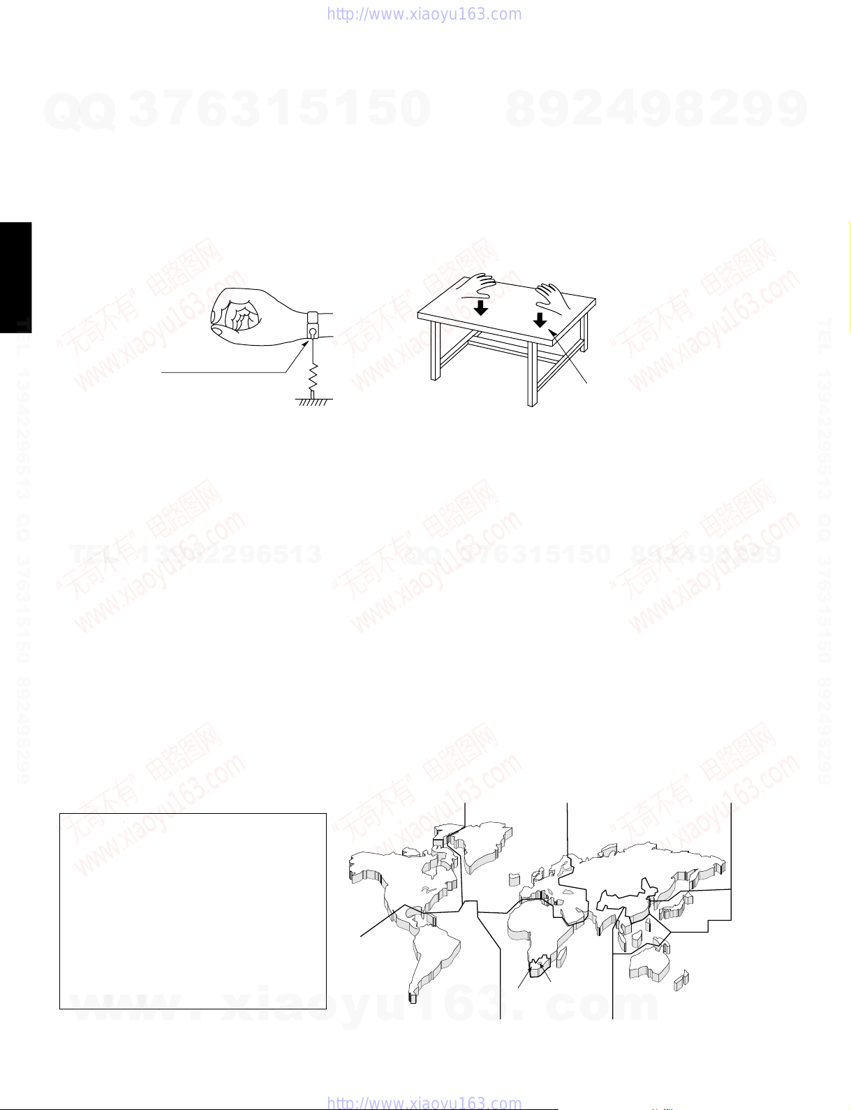
■ PREVENTION OF ELECTROSTATIC DISCHARGE
The laser diode in the traverse unit (optical pickup) may be damaged due to static electricity from clothes or the human
Q
Q
body. Use caution to prevent electrostatic damage when servicing or handling the laser diode.
1. Grounding for electrostatic damage prevention
1. Worktable grounding
Put a grounded conductive material (sheet) or iron sheet on the area where the optical pickup is placed.
2. Human body grounding
Use an anti-static wrist strap to discharge the static electricity from your body.
DVD-C940
/DV-C6680
TEL 13942296513 QQ 376315150 892498299
2. Handling of the optical pickup
1. To prevent damage to the optical pickup replacement parts during transportation and before installation, both ends
of the laser diode are short-circuited. After installing the new part, remove the short circuit according to the correct
procedure in this service manual.
2. Do not use a tester to check the laser diode in the optical pickup. The power supply in the tester will damage the
laser diode.
7
3
Anti-static wrist strap
6
3
1
5
1
1MΩ
5
0
8
2
9
Conductive material
(sheet) or steel sheet
4
9
8
2
9
9
TEL 13942296513 QQ 376315150 892498299
3. Handling Precautions for the Traverse Unit (Optical Pickup)
TEL
1. Handle the traverse unit (optical pickup) gently, as it is an extremely high-precision assembly.
2. The flexible cable lines may break if an excessive force is applied to it. Use caution when handling the cable.
3. The semi-fixed resistor for laser power adjustment should not be adjusted. Do not turn the resistor.
■ LOCALE MANAGEMENT INFORMATION
Locale Management Information : This DVD player is designed and manufactured to respond to the Locale
Management Information that is recorded on a DVD disc. If the Locale number described on the DVD disc does not
correspond to the Locale number of this DVD player, this DVD player cannot play this disc.
This product incorporates copyright
protection technology that is protected by
method claims of certain U.S. patents and
other intellectual property rights owned by
Macrovision Corporation and other rights
owners. Use of this copyright protection
technology must be authorized by
Macrovision Corporation, and is intended
for home and other limited viewing uses
only unless otherwise authorized by
Macrovision Corporation. Reverse
engineering or disassembly is prohibited.
w
13942296513
w
w
.
xia
o
q
y
r
u
Q
1
Q
3
6
6
7
3
3
w
.
1
w
1
5
t
c
0
5
t
o
9
8
t
y
m
8
9
4
2
w
e
r
2
9
9
4
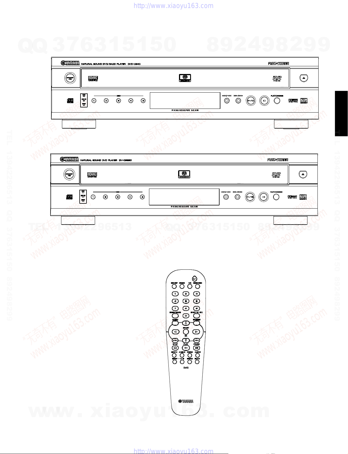
■ FRONT PANELS
DVD-C940/DV-C6680
Q
TEL 13942296513 QQ 376315150 892498299
▼ DVD-C940 (U model)
Q
▼ DV-C6680 (U model)
3
7
6
3
1
5
1
5
0
8
9
2
4
9
8
2
9
9
/DV-C6680
DVD-C940
TEL 13942296513 QQ 376315150 892498299
TEL
13942296513
3
6
7
3
Q
Q
● DVD-C940/DV-C6680
1
5
1
5
0
8
9
2
4
9
8
2
9
9
w
w
w
.
xia
o
y
u
1
6
3
.
c
o
m
5
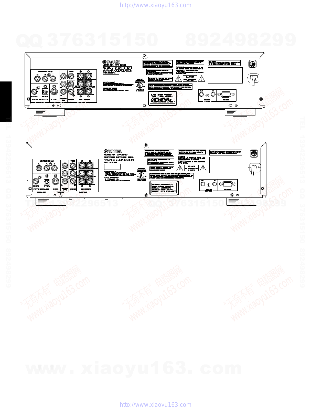
DVD-C940/DV-C6680
■ REAR PANELS
▼ DVD-C940 U model
Q
Q
DVD-C940
/DV-C6680
TEL 13942296513 QQ 376315150 892498299
▼ DV-C6680 U model
3
7
6
3
1
5
1
5
0
8
9
2
4
9
8
2
9
9
TEL 13942296513 QQ 376315150 892498299
TEL
13942296513
Q
Q
3
7
6
3
1
5
1
5
0
8
9
2
4
9
8
2
9
9
6
w
w
w
.
xia
o
y
u
1
6
3
.
c
o
m
■ SPECIFICATIONS
DVD-C940/DV-C6680
Q
TEL 13942296513 QQ 376315150 892498299
TEL
PLAYBACK SYSTEM
Q
DVD Video
SACD multichannel and SACD stereo
DVD+RW
DVD+R
Video CD and SVCD
CD (CD-R and CD-RW)
MP3 CD
TV STANDARD (PAL/50Hz) (NTSC/60Hz)
Number of lines 625 525
Playback Multistandard (PAL/NTSC)
VIDEO PERFORMANCE
Component video output Y: 1Vpp into 75 ohm
S-Video output Y: 1Vpp into 75 ohm
Video output 1 Vpp into 75 ohm
Black Level Shift On/Off
Video Shift Left/Right
AUDIO FORMAT
DSD Multichannel and Stereo
Dolby Digital/ Compressed Digital
DTS/MPEG
PCM 16, 20, 24 bits
MP3 96, 112, 128, 256 kbps and
(Joliet) variable bit rate fs 32, 44.1, 48kHz
Full decoding of Dolby Digital and DTS multi channel sound
Analog Stereo Sound
Dolby Surround-compatible downmix from Dolby Digital
multi-channel sound
3D Sound for virtual 5.1 channel sound on 2 speakers
SACD AUDIO PERFORMANCE
D/A Converter DSD
SACD fs 2.8224MHz DC - 100kHz
Max. output voltage (0dB) 2V rms
Channel unbalance <0.5 dB
Cut-off frequency 50 kHz (Front)
Signal-Noise (1kHz) 105 dB
Dynamic Range (1kHz) 100 dB
Harmonic Distortion + Noise (1kHz) 0.0025%
3
7
6
1
3
Pr/Cr Pb/Cb: 0.7Vpp into 75 ohm
C: 0.3Vpp into 75 ohm
13942296513
fs, 44.1, 48, 96 kHz
40 kHz (Surround, Center,
Subwoofer)
5
1
5
0
Q
Q
Dynamic Range (1kHz) 100 dB
Harmonic Distortion + Noise (1kHz) 0.0025%
MPEG MP3 MPEG Audio L3
CONNECTIONS
Y Pb/Cb Pr/Cr (480i/p) Cinch 3x (green, blue, red)
S-Video Output Mini DIN, 4 pins
Video Output Cinch (yellow)
Audio L+R output Cinch (white/red)
Digital Output 1 coaxial, 1 optical
Remote Control In/Out Mini jack, Mono
RS-232C D-sub, 9 pins
6 channel analog output
Audio Front L/R Cinch (white/red)
Audio Surround L/R Cinch (white/red)
Audio Center Cinch (blue)
Audio Subwoofer Cinch (black)
CABINET
Dimensions (w x h x d) 435 x 116 x 425 mm
Weight Approx. 6 Kg (13 lbs 3 oz)
POWER SUPPLY
7
3
Power input 120V, 60Hz
Power usage Approx. 24W
Power usage standby < 5W
Finish
DVD-C940 Black color (U model)
DV-C6680 Black color (U model)
Accessories
* typical playing time for movie with 2 spoken languages and 3
Specifications subject to change without prior notice
Manufactured under license from Dolby Laboratories.
“Dolby”, “Pro Logic” and the double-D symbol are trademarks of
Dolby Laboratories.
9
8
1
5
1
3
6
subtitle languages
4
2
0
5
Remote Control, Batteries, Audio/Video Cable
9
IEC958 for CDDA / LPCM
IEC1937 for MPEG1/2, Dolby
Digital, DTS
(17-1/8" x 4-9/16" x 16-3/4")
2
9
8
8
4
2
9
8
9
2
9
9
9
/DV-C6680
DVD-C940
TEL 13942296513 QQ 376315150 892498299
w
w
AUDIO PERFORMANCE
DA Converter 24 bits
DVD fs 96 kHz 2 Hz - 44 kHz
fs 48 kHz 2 Hz - 22 kHz
CD/Video CD fs 44.1 kHz 2 Hz - 20 kH z
S-Video CD fs 48 kHz 2 Hz - 22 kHz
w
Signal-Noise (1kHz) 110 dB
.
xia
o
y
fs 44.1 kHz 2 Hz - 20 kHz
u
1
Manufactured under license from Digital Theater Systems, Inc.
US Pat. No.5,451,942, 5,956,674, 5,974,380, 5,978,762 and
other world-wide patents issued and pending. “DTS” and “DTS
Digital Surround” are registered trademarks of Digital Theater
Systems, Inc. Copyright 1996,2000 Digital Theater Systems,
Inc. All Rights Reserved.
6
3
.
c
o
m
“DCDi” is a trademark of Faroudia, a division of Sage Inc.
7

DVD-C940/DV-C6680
■ DIMENSIONS
7
Q
Q
DVD-C940
/DV-C6680
TEL 13942296513 QQ 376315150 892498299
3
6
3
1
5
1
5
435 (17-1/8")
0
9
8
425 (16-3/4")
116
(4-9/16")
Unit : mm (inch)
2
4
9
8
2
9
9
TEL 13942296513 QQ 376315150 892498299
■ INTERNAL VIEW
TEL
13942296513
9
9
2
8
9
4
2
9
8
0
5
1
5
1
3
6
7
3
Q
Q
r t yq w e
q POWER SUPPLY UNIT
w RS-232C P.C.B.
e CM UNIT
r CLAMPER ASS’Y
t AV P.C.B.
y P-SCAN P.C.B.
u TRAY ASS’Y
i MONO BOARD P.C.B.
8
w
w
w
.
xia
u i
o
y
u
1
6
3
.
c
o
m
■ DISASSEMBLY PROCEDURES
t
DVD-C940/DV-C6680
Q
TEL 13942296513 QQ 376315150 892498299
Q
See exploded view for item numbers
3
➔ Remove cable connection.
➔ Unlock Front panel from frame by
releasing successively 4 snaps.
(2 on the side and bottom)
➔ Place Front panel in front of
the set ( service position ).
7
Front Panel 0001
6
3
1
5
1
5
0
Top Cover 300
➔ Remove 4 screws 310 and
3 screws 305
➔ Lift top cover from rear side
to remove.
Tray Ass’y
➔ Removes stopper screw 10 on
the Tray.
➔ Open Tray
(See instruction for manual
eject of tray)
➔ Gently pull the tray out.
8
9
2
➔ Open Tray
(See instruction for manual
eject of tray)
➔ Removes flex connection.
➔ Remove screw 275
(skt cinch to back-plate) and
screw 195 (board to bracket)
➔ Dismount board
4
Mounting
Dismounting
P-scan board 1003
9
8
2
Power supply unit 1005
➔ Remove cable connections.
➔ Remove 2 screws 185.
(Board to bottom frame)
➔ Release spacer locking.
(Board to bottom frame)
➔ Dismount board.
9
9
TEL 13942296513 QQ 376315150 892498299
T
E
L
Front Display board 2000 (1)
➔ Remove 8 screws 100.
(Board to Front cabinet)
➔ Remove cable connections.
➔ Dismount board.
➔ Remove 3 screws 0120.
1
➔ Remove Shield Plate.
Front Eject board 2000 (2)
➔ Remove 3 screws 115.
(Board to Front cabinet)
➔ Remove cable connection.
➔ Dismount board.
Shield Plate
3
9
4
2
2
9
6
Front Standby board 2000 (3)
➔ Remove 2 screws 110.
(Board to Front cabinet)
➔ Remove cable connection.
➔ Dismount board.
5
1
3
Clamper Ass’y 0004
➔ Remove 2 screws 12.
(Clamper to CM unit )
➔ Dismount clamper ass’y.
Holder/VAM Ass’y
➔ Remove 2 screws 11.
(Holder/VAM Ass’y to CM
unit)
➔ Dismount holder /VAM ass’y.
When disassembling, use the special screw driver with
tip shape in figure.
T20
3.8 mm
Q
Q
1
3
6
7
3
CM Unit
➔ Remove P-scan board 1003,
AV board 1001 and
Monobaord 1020.
➔ Remove 5 screws 150.
(CM module to bottom frame)
➔ Dismount CM uni
Motor driver board 1021
➔ Flip the CM unit.
➔ Release 3 catches.
➔ Remove cable connections
➔ Dismount board.
5
1
➔ Remove flex and cable
connections.
➔ Remove 4 screws 275
(skt cinch ,optical to back plate) and screw 280.
(S-video to back-plate)
➔ Release 2 screw 190.
(board to bracket)
➔ Dismount board.
➔ Remove flex and cable
connections from Changer
module to Monoboard.
➔ Remove 4 screws 200.
➔ Dismount Monoboard.
A/V board 1001
Monoboard
0
5
8
1020
9
2
4
9
RS-232C board 1111
➔ Remove cable connections.
➔ Remove 2 screws 265 and
screw 270.
(Board to Rear Panel)
➔ Release 2 spacers locking.
(Board to bottom frame)
➔ Dismount board.
9
9
2
8
w
w
w
.
x
i
a
T10
T6
o
2.7 mm
1.7 mm
y
u
1
6
3
.
c
o
m
9

DVD-C940/DV-C6680
Q
TEL 13942296513 QQ 376315150 892498299
Top Cover
Tray
Q
1
3
4
7
6
3
1
HOW TO MANUALLY EJECT THE TRAY
1. Remove the Top Cover.
2. Move the gear in the anti-clockwise direction
with your finger until the tray is ejected.
3. Gentlely pull the tray out.
5
2
1
5
0
8
2. Removal of Table
9
a. Remove 2 screws ( t ) and then remove the
Support/M in Fig. 3.
b. Remove the Plate/Table in Fig. 3.
c. Remove 1 screw ( y
Fig. 3.
Plate/Table
2
y
4
) and then take off the Table in
t
Support/M
9
Fit the table to the thick line on “ / ” mark.
t
8
2
9
9
TEL 13942296513 QQ 376315150 892498299
T
E
L
3
1. Removal of Tray Ass'y
a. Remove 1 screw ( r ) in Fig. 1.
b. Turn Gear/L0 as shown in Fig. 2 counter clockwise
gradually until immediately before the tray starts to
move and stop it there.
CAUTION: Gear/L0, if turned counter clockwise con-
tinuously, will mesh with the gear of the tray
and the tray will come out. When removing
the tray, use care so that Gear/L0 will not
mesh with the gear of the tray.
c. Pull out the Tray Ass'y.
1
Tray
3
9
4
2
2
9
6
5
1
3
Fig. 1
● Precaution for installation of the Tray Ass'y.
On Tray Ass'y setting.
Check the Direction of marking “▲” on gear
according to this drawing.
Gear/L0
Q
Q
3
7
6
3
0
5
1
5
1
Table
IMPORTANT: Installation of Table.
Install the table according to the following procedure.
1) Slide the Lever so that the Gear/RT becomes
free. (Fig.B)
2) With the “▲” mark on the Gear/RT aligned
with the same mark on the Tray, lock it with
the Lever. (Fig.B)
3) Install the Table by aligning it to the thick line
/ ” mark. (Fig.3)
on “
*Check that the Table is locked after installation.
Gear/RT1
Tray
Lever
Lock
4
2
9
8
Fit the Gear/RT to “▲” mark.
9
Fig. 3
8
2
9
9
10
w
w
Gear/L0
w
.
Fig. 2
x
i
Gear/L01
a
o
Marking
Front Panel
y
u
Fig. A
1
6
3
.
c
Unlock
o
Fig. B
m

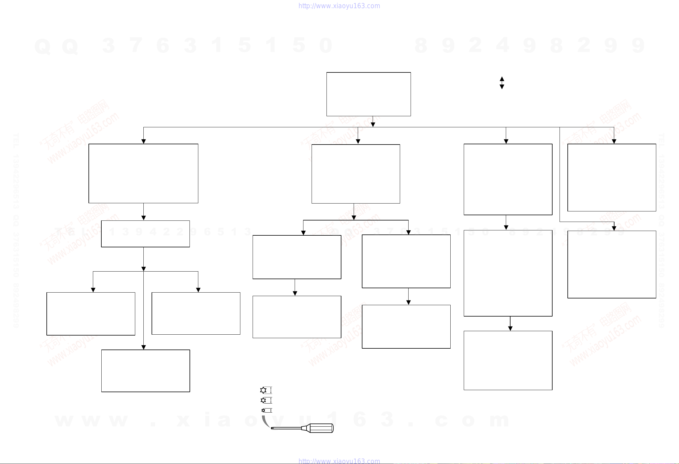
1 Dealerscript
1.1 Purpose of Dealer Script
1.2 Contents of Dealer Script
The dealer script executes all diagnostic nuclei that do not
need any user interaction and are meaningful on a standalone
DVD player.
The nuclei called in the dealer script are the following (the
number after each nucleus name corresponds with the number
being on the local display when the nucleus is executed during
the dealer script):
Nucleus
Figure 1 D ealer script nuclei
Figure 2 Dealer Script
9 6 PapChksFl
8
Checks the I2C interface with the slave processor
on the Display board
13
Press 2 keys simultaneously
<OPEN/CLOSE> + <PLAY/PAUSE>
Connect to mains.
During the test, the following display
is shown: the counter counts down
from the number of nuclei to be run
before the test finishes. Example:
SET O.K.?
YES
NO
To exit DEALER SCRIPT, disconnect from mains
Display
Countdown
Nucleus
Number
Nucleus Name Description
Calculate and verify checksum of FLASH memory
12 PapI2cDisp
7
92c ChangerI2cExp
Checks the I2C interface with the IO expander
on the Buffer board
6 29a
PapI2cLedExp
Checks the I2C interface with the IO expander
on the Display board
5
PapS2bEcho Checks the I2C interface to the basic engine
411
PapI2cNvram
Checks the I2C interface to the basic engine
315
PapNvramWrR Pattern test of all locations in the NVRAM
2 16 Pattern test of all locations in the SDRAM(s)
1
63
FURORERSdramWrRLow
Pattern test of all locations in the SDRAM(s)
CompSdramWrR
The dealer script can give a diagnosis on a standalone DVD
player, no other equipment is needed to perform a number of
hardware tests to check if the DVD player is faulty. The
diagnosis is simply an "error" or "pass" message. No
indication is given of faulty hardware modules. Only tests
within the scope of the diagnostic software will be executed
hence only faults within this scope can be detected.
■ DIAGNOSTIC SOFTWARE
DVD-C940/DV-C6680
7
Q
Q
TEL 13942296513 QQ 376315150 892498299
TEL
3
13942296513
6
3
1
5
1
5
0
Q
Q
3
2
9
8
1
5
1
3
6
7
5
0
4
9
8
9
8
2
4
2
9
8
9
2
9
9
9
/DV-C6680
DVD-C940
TEL 13942296513 QQ 376315150 892498299
xia
w
w
w
.
o
y
u
1
6
3
.
c
o
m
11
DVD-C940/DV-C6680
s
2 Player Script
2.1 Purpose of Player Script
Q
Q
The Player script will give the opportunity to perform a test that
will determine which of the DVD player's modules are faulty, to
read the error log and error bits and to perform an endurance
loop test. To successfully perform the tests, the DVD player
must be connected to a TV set to check the output of a number
of nuclei. For DVDv2b a multi-channel amplifier, a set of 6
speakers and an external video source are necessary to test.
To be able to check results of certain nuclei, the player script
expects some interaction of the user (i.e. to approve a test
picture or a test sound). Some nuclei (e.g. nuclei that test
functionality of the Basic Engine module) require that the DVD
player itself is opened, to enable the user to observe moving
DVD-C940
/DV-C6680
TEL 13942296513 QQ 376315150 892498299
parts and approve their movement visually. Only tests within
the scope of the diagnostic software will be executed hence
only faults within this scope can be detected.
2.2 Contents of Player Script
The player script contains all nuclei that are useful on a DVD
player that is connected to a TV set and help to determine
which module of the DVD player is faulty, as well as to read out
the contents of the error logs.
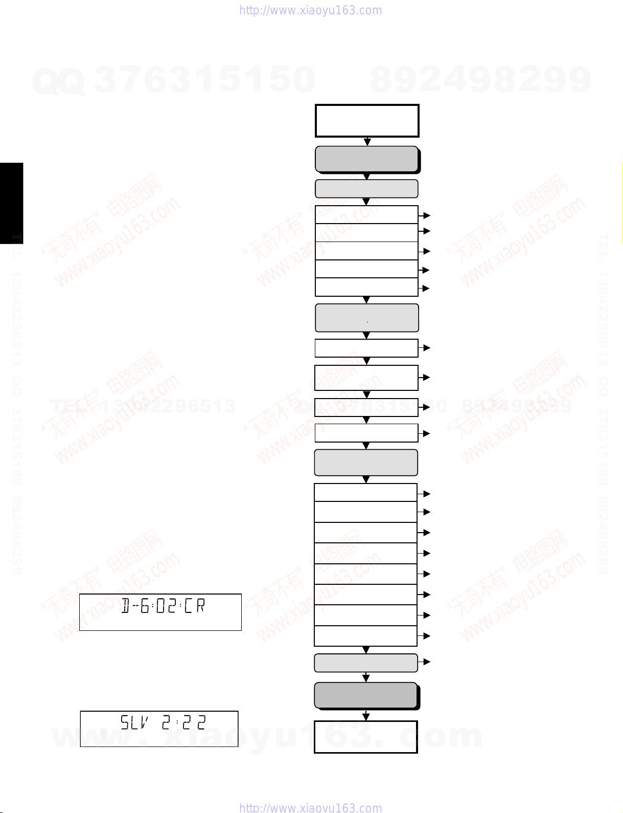
2.3 Structure of Player Script
The player script consists of a set of nuclei testing the three
hardware modules in the DVD player: the Display PWB, the
Digital PWB, and the Basic Engine.
Nuclei run by the player test need some user interaction. In the
next paragraph this interaction is described. The player test is
done in two phases:
TEL
1. Interactive tests: this part of the player test depends
strongly on user interaction and input to determine nucleus
results and to progress through the full test. Reading the
error log and error bits information can be useful to
determine any errors that occurred recently during normal
operation of the DVD player.
The loop test: this part of the player test will loop through
2.
the list of nuclei indefinitely, untill the player is reset. The
list of nuclei is as follows:
PapChksFlash
PapI2cNvram
CompSdramWrR
PapS2bEcho
PapI2cDisp
At the beginning of the tests, the DSW version number will be
indicated on the local display of the DVD.
The display will look like the following:
3
7
6
3
1
13942296513
ChangerI2cExp
PapI2cLedIOExp
FURORERSdramWrRLow
PapNvramWrR
5
1
5
0
Q
Press the PLAY/PAUSE key to proceed to the next test.
5.2.4 Survey
Press 2 keys simultaneously
<OPEN/CLOSE> + <STOP>
Connect to main
INTERACTIVE TESTS
DISPLAY PCB
DISPLAY TEST
LED TEST
KEYBOARD TEST
REMOTE CONTROL
P50 LOOP BACK TEST
MONO PCB
DIGITAL PART
PICTURE TEST
SOUND 1 TEST
SCART DVD TEST
SCART LOOP TEST
3
Q
SOUND 2 TEST
MONO PCB(SERVO)
& BASIC ENGINE
VERSION NUMBER
TRAY TEST
SLEDGE TEST
DISC MOTOR TEST
FOCUS TEST
RADIAL TEST
7
6
8
3
9
1
5
4
2
DispDisplay (30a)
DispLed
DispKeyb (27)
DispRc (28)
DispP50 (60)
VideoColDencOn (23a)
AudioPinkNoiseOn (20a)
VideoScartSwDvd (55a)
VideoScartSwPass (55b)
8
0
5
1
AudioSineOn (21a)
BeVer (37)
BeTrayOut/In (43a/b)
ChangerTrayOut/In (91b/c)
BeSledgeOut/In (41a/b)
BeDiscMotorOn (39a/b)
BeFocusOn (38a/b)
BeRadialOn (40a/b)
9
9
8
2
4
2
9
8
9
2
9
9
TEL 13942296513 QQ 376315150 892498299
9
12
Figure 3
Pressing the PLAY/PAUSE key will proceed to the slave S /W
version display, which is shown on the local display of the
DVD player.
The display will look like the following:
w
w
w
.
xia
Figure 4
o
JUMP TEST
TRAY TEST
ERROR LOG & BITS
LOOP TEST
To exit player test,
y
u
disconnect from mains
1
6
3
.
c
Figure 5
BeGroovesIn/Mid/Out (42a/b/c)
BeTrayOut/In (43a/b)
LogReadErr (31)
LogReadbits (32)
= Dealer script exclusive of test2
o
m

3 Display PCB
Q
TEL 13942296513 QQ 376315150 892498299
3.1 Display Test
Q
7
3
The display test is performed by nucleus DispDis play. By
putting a series of test patterns on the local display, the local
display is tested. To step through all different patterns, the user
must either press OPEN/CLOSE (pattern is ok) or STOP
(pattern was incorrect) to proceed to the next pattern. The
display of patterns is continued in a cyclic manner, shown in
Fig. 6, until the user presses PLAY/PAUSE. If the user presses
PLAY/PAUSE before all display patterns are tested, the
DispDisplay nucleus will return FALSE (display test
unsuccessful).
6
If OK, press OPEN/CLOSE
If OK, press OPEN/CLOSE
If OK, press OPEN/CLOSE
press PLAY/PAUSE to continue
3
1
5
If NOK, press STOP
If NOK, press STOP
If NOK, press STOP
1
5
0
DVD-C940/DV-C6680
KEY ID KEY
0
9
8
1
2
3
4
5
H
I
J
K
L
M
If any keys are detected more than once (due to hardware
error), the key-code is displayed twice (or more), with the
second digit increased by 1.
If the user does not press all keys minimally once (in any
order), the DispKeys nucleus will return FALSE and cause an
error in the overall result of the player script.
The user can leave the keyboard test by pressing the
PLAY/PAUSE key on the local keyboard of the DVD player
for at least one full second.
The result of the keyboard test is shown on local display as
follows:
PLAY / PAUSE
4
2
STOP
OPEN / CLOSE
STANDBY / ON
NEXT
PREVIOUS
PLAYXCHANGE
DISC 1
DISC 2
DISC 3
DISC 4
DISC 5
9
w/d
8
r/y
t/e
2
a
v
9
Figure 8
9
/DV-C6680
DVD-C940
TEL 13942296513 QQ 376315150 892498299
TEL
Figure 6
13942296513
3.2 LED Test
The LED(s) on the DVD player is (are) tested by nucleus
DispLed.
There are three test patterns for the LED test which can be
stepped through using the OPEN/CLOSE key.
The user must check if the LED(s) is (are) lighted; if it is, press
OPEN/CLOSE, if the LED did not light up, the user must press
STOP key. By pressing PLAY/PAUSE before OPEN/CLOSE or
STOP,
the Displed nucleus will return TRUE (LED test successful).
3.3 Keyboard Test
The keyboard of the DVD player is tested by nucleus
DispKeyb. The user is expected to press all keys on the
local keyboard once. The code of the key pressed is shown
on the local display (1 hexadecimal digit) immediately
followed by a (hexadecimal) number indicating how many
times that key has been pressed. Example of the local
display during this test:
Figure 7
Q
Q
1
5
1
3
6
7
3
Or
Pressing PLAY/PAUSE on the local keyboard again will
proceed to the next text.
3.4 Remote Control Test
The remote control of the DVD player is tested by nucleus
DispRc. The user must press any key on the remote control
just once. The codes of the key pressed will be shown on the
local display in hexadecimal format. Example:
5
0
Figure 9
Figure 10
8
9
2
4
9
8
2
9
9
w
w
The key-codes displayed on the local display will scroll from
right to left when the display gets full, the text "K" will remain
on display.
w
.
xia
o
y
u
1
6
Figure 11
3
.
c
o
In this example, 23 is the hexadecimal code of the pressed
RC key. The user can leave the remote-control test by
pressing PLAY/PAUSE on the local keyboard of the DVD
player. The remote control test is successful if a code was
received before the user pressed the PLAY/PAUSE key.
m
13

DVD-C940/DV-C6680
Pressing the PLAY/PAUSE key, before pressing a key on the
remote control, gives an error in the remote control test (note
that the remote control test will also fail if a key on the remote
control was pressed but no code was received). The remote
Q
Q
control test does not check upon the contents of the received
code, that is it will not be checked if the received code
matches the key pressed. If desired, the user can manually
check this code by using a code-table for the remote control
key-codes.
3
7
6
3
1
5
1
5
0
8
9
Figure13
2
4
9
8
2
9
9
RC Key id Hexadecimal code
STANDBY
DISC SKIP
DIMMER
DVD-C940
TEL 13942296513 QQ 376315150 892498299
T/C
/DV-C6680
SOUND MODE
1
2
3
4
5
6
7
8
9
0
RETURN/RESUME
TEL
CD TEXT/BIT RATE
MENU
ON SCREEN
CURSOR UP
CURSOR DOWN
CURSOR LEFT
CURSOR RIGHT
OK
PREVIOUS
NEXT
STOP
PLAY
PAUSE
SUBTITLE
ANGLE
ZOOM
AUDIO
REPEAT
REPEAT A-B
SHUFFLE
SCAN
13942296513
t
y
a
w
d
0C
7F
13
C8
50
01
02
03
04
05
06
07
08
09
00
83
48
54
82
58
59
5A
5B
5C
21
20
31
2C
30
4B
85
F7
4E
1D
3B
1C
2A
Or
Pressing PLAY/PAUSE on the local keyboard again will
proceed to the next test.
3.5 P50 Loop-Back Test
For the P50 loop-back test, the user must first press a key to
decide if the test is to be performed.
The display will show the following message:
3
Q
Q
If the user presses STOP, the P50 test will be skipped.
If the user presses OPEN/CLOSE, the P50 test is performed
and the result is displayed as follows:
Test successful:
Test fails:
Press the PLAY/PAUSE key to continue to the next text
7
6
Figure 14
1
3
Figure 15
Figure 16
Figure 17
5
1
5
0
8
9
2
4
9
8
2
9
TEL 13942296513 QQ 376315150 892498299
9
w
w
After pressing PLAY/PAUSE, the result of the remote control
test is displayed on the local display of the DVD player as
follows:
14
Figure 12
w
.
xia
o
y
u
1
6
3
.
c
o
m
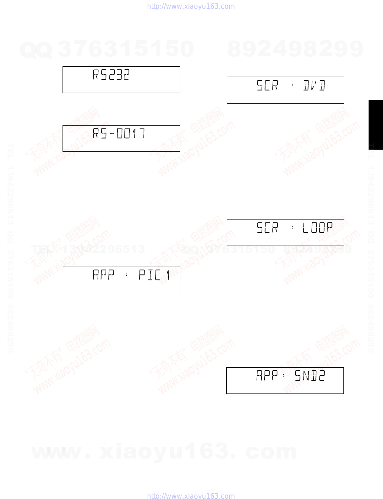
3.6 RS232C Test
Figure 18
4.2 Sound 1 & SCART DVD Test
Figure 21
Figure 22
4.3 Sound 2 Test
Figure 23
4 Mono PCB Digital Part
4.1 Picture Test
Figure 20
Figure 19
After the audio signal has been stopped by pressing
OPEN/CLOSE, the user confirms the test. Pressing STOP will
indicate that something went wrong. Pressing PLAY/PAUSE
will proceed to the next. If the user presses PLAY/PAUSE
without pressing OPEN/CLOSE or STOP first, the result of this
test will be TRUE (sound ok).
The test can be left by pressing the PLAY/PAUSE key for
more than one second.
On the TV screen a color bar (generated by nucleus
VideoColDencOn) is visible and the internally generated
pinknoise is audible.
By pressing the PLAY/PAUSE key, the user confirms the test.
Pressing the STOP key will indicate the sound was inaudible
or incorrect.
Note: Only for double scart models, SCART loop-through will
be simultaneously active during this test. SCART loop-through
will be measured with the aid of an external video source.
By pressing the PLAY/PAUSE key, the video will be switched
over to the external source. This must now become visible on
the TV screen (using the SCART).
The local display will show the following message:
The display will show as in Figure 18 for about 1 second and
then as in figure 19.
By pressing OPEN/CLOSE the user confirms the test, pressing
STOP will indicate the picture was invisible or incorrect.
Pressing PLAY/PAUSE will proceed to the next test. If the user
presses PLAY/PAUSE without pressing OPEN/CLOSE or STOP
first, the result of this test will be TRUE (picture ok).
The picture test is performed by putting a predefined picture
(color bar PAL) on the display (nucleus VideoColDencOn),
and asking the user for confirmation.
The display will show the following message:
Note: The color bar must be simultaneously available on the
CVBS, YC, and RGB (or YUV) outputs available. On the SCART
only the CVBS and RGB signals will be available.
The first sound test is performed by starting a pink noise sound
that needs confirmation from the user (nucleus
AudioPinkNoiseOn).
The display will show the following message:
The internally generated color bar is still available on the CVBS
and Y/C outputs. And the pinknoise-signal is still available on
the cinch audio outputs. By pressing the OPEN/CLOSE button,
the internally generated color bar becomes visible again.
The second sound test is performed by producing a sine sound
(nucleus AudioSineOn). The signal can be stopped by pressing
the STOP key.
The display will show the following message:
Press the PLAY/PAUSE key to continue to the next test.
DVD-C940/DV-C6680
7
Q
Q
TEL 13942296513 QQ 376315150 892498299
TEL
3
13942296513
6
3
1
5
1
5
0
Q
Q
3
6
7
8
3
9
1
5
2
1
5
0
4
9
8
9
8
2
4
2
9
8
9
2
9
9
9
/DV-C6680
DVD-C940
TEL 13942296513 QQ 376315150 892498299
w
w
w
.
xia
o
y
u
1
6
3
.
c
o
m
15
DVD-C940/DV-C6680
5 Basic Engine
5.1 Version Number
Q
Q
In the basic engine tests, the version number of the Basic
Engine will be shown first, as in the following example:
DVD-C940
/DV-C6680
TEL 13942296513 QQ 376315150 892498299
By pressing the PLAY/PAUSE key, the Basic Engine tests are
started.
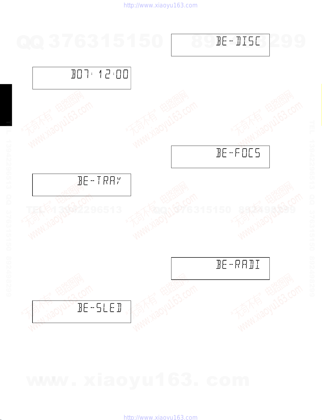
5.2 Tray Test
First, the tray is tested. The purpose of this test is also to give
the user the opportunity to put a disc in the tray of the DVD
player. Some tests on the Basic Engine require that a disc (e.g.
DVD MPTD test disc) is present in the player. At the end of the
Basic Engine tests this tray test will be repeated solely to
enable the user to remove the disc in the tray.
The local display will look as follows:
TEL
By pressing OPEN/CLOSE the user can toggle the position of
the tray. Note that this test will not contribute to the test result of
the Basic Engine. Pressing PLAY/PAUSE will proceed to the
next test. At this point, the tray will be closed automatically by
the software if it was open.
5.3 Sledge Test (Visual Test)
7
3
13942296513
6
Figure 24
Figure 25
3
1
5
1
5
0
By pressing OPEN/CLOSE the user confirms that the disc
motor is running. Pressing STOP indicates the disc motor
does not work. Pressing PLAY/PAUSE proceeds to the next
test, after a reset of the disc motor (nucleus BeDiscMotorOff).
If the user presses PLAY/PAUSE before pressing
OPEN/CLOSE or STOP, the result of this test will be TRUE
(disc motor is running).
5.5 Focus Test (Visual Test)
The fourth Basic Engine test tests the focussing. First
focussing is turned on by calling nucleus BeFocusOn.
The display will look as follows:
By pressing OPEN/CLOSE the user confirms that the
focussing was successful. Pressing STOP indicates a
focussing failure. Pressing PLAY/PAUSE proceeds to the next
test after a reset of the focussing (nucleus BeFocusOff). If
PLAY/PAUSE is pressed before OPEN/CLOSE or STOP, the
3
Q
Q
result of this test will be TRUE (focus successful).
5.6 Radial Test (Visual & Listening Test)
The fifth Basic Engine test tests the radial functionality (nucleus
BeRadialOn).
The local display looks as follows:
7
6
8
3
9
1
2
Figure 27
Figure 28
1
5
5
0
4
9
8
9
8
2
4
2
9
8
9
2
9
9
TEL 13942296513 QQ 376315150 892498299
9
The second Basic Engine test tests the sledge. The user can
move the sledge as many times as desired by using OPEN/
CLOSE (nucleus BeSledgeOut) and STOP (nucleus
BeSledgeIn). Pressing PLAY/PAUSE on the local keyboard
proceeds to the next test. Note that this test will not contribute to
the test result of the Basic Engine.
The local display will look as follows during the sledge test:
5.4 Disc Motor Test (Visual Test)
The third Basic Engine test tests the disc motor (nucleus
BeDiscMotorOn).
The local display looks as follows:
w
w
w
16
Figure 26
.
xia
o
y
u
By pressing OPEN/CLOSE the user confirms that the radial
function works. Pressing STOP indicates the function does not
work. Pressing PLAY/PAUSE proceeds to the next test, after a
reset of the radial (nucleus BeRadialOff). If the user presses
PLAY/PAUSE before pressing OPEN/CLOSE or STOP, the
result of this test will be TRUE (radial successful).
5.7 Jump Test (Listening Test)
The sixth and last Basic Engine test tests the jumping by calling
nuclei BeGroovesIn, BeGroovesMid and BeGroovesOut.
During this test, the local display looks as follows:
1
6
3
.
Figure 29
c
o
m
DVD-C940/DV-C6680
7
Q
Q
TEL 13942296513 QQ 376315150 892498299
TEL
3
The user can switch between the three different types of
groove settings by pressing OPEN/CLOSE (forward to next
nucleus in the list In-Mid-Out), or STOP (backward in the list
In-Mid-Out). This is done in a cyclic manner; note that this
test will not contribute to the test result of the Basic Engine.
Pressing PLAY/PAUSE proceeds to the next test, after the
disc motor has been shut off with a call to nucleus
BeDiscMotorOff.
5.8 Tray Test
As a last action for the Basic Engine tests, the tray test is
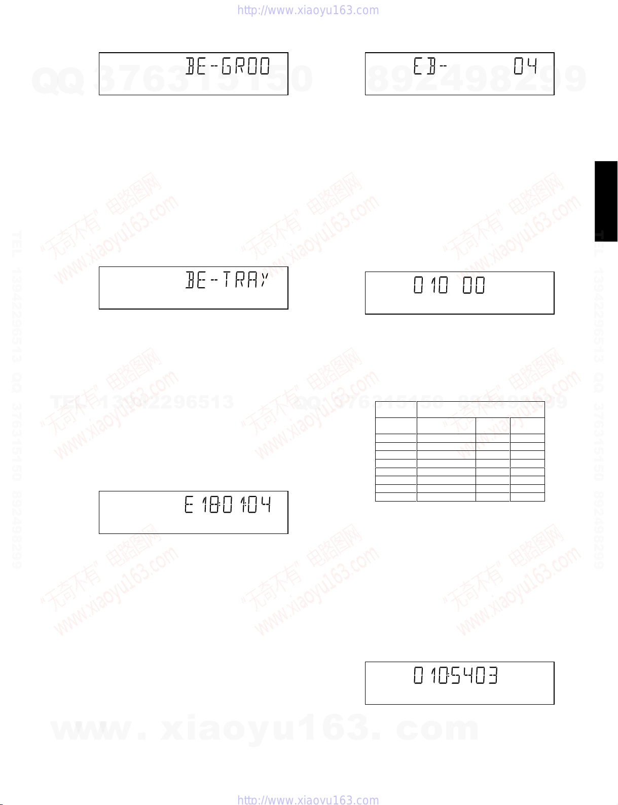
repeated. The local display will look as follows:
This test is meant to give the user the opportunity to remove
the disc in the tray. The tray position can be toggled using the
OPEN/CLOSE key. The tray will be closed (by the software, if
it is open) before proceeding to the next test when the user
presses the PLAY/PAUSE key.
13942296513
5.9 Error Log (See Table on Next Page)
Reading the error log and error bits information can be useful
to determine any errors that occurred recently during normal
operation of the DVD player. Reading the error log is done by
nucleus LogReadErr.
The display during the errorlog readout looks as follows :
6
3
Figure 30
Figure 31
1
5
1
5
0
Q
Q
3
7
4
2
9
8
Only the identification number (decimal) representing set
errorbits will be shown. By pressing OPEN/CLOSE or STOP,
the user can move forward or backward (respectively) through
the logged error codes. If the display only shows "EB-0", no
error bits were set. By pressing PLAY/PAUSE the user can
continue to the next test.
6 Loop Test (See Table Below)
At the start of the loop test, the local display of the DVD player
will show the interactive player test result readout in the
following display:
The left side of the display contains a 3-digit code, which can
have a value between 000 and 111. These values indicate the
faulty modules and are to be interpreted as follows:
Displayed
1
3
6
Value
000 ok ok ok
001 ok ok faulty
010 ok faulty ok
011 ok faulty faulty
100 faulty ok ok
101 faulty ok faulty
110 faulty faulty ok
111 faulty faulty faulty
Indication for each module
0
5
1
5
Basic Engine Mono
9
Figure 33
Figure 34
8
9
2
PCB
8
4
2
9
Display
PCB
8
2
9
9
9
9
/DV-C6680
DVD-C940
TEL 13942296513 QQ 376315150 892498299
w
w
Figure 32
Note: Previous versions of the diagnostic software showed a 8-
digit error code.
Due to limitations in the number of digits that can be displayed
by some front panel displays, the most significant digits will not
be shown. This can be done since all the error codes used by
this player has set these 2 digits to ì00î
By pressing OPEN/CLOSE or STOP the user can move
forward or backward (respectively) through the logged error
codes. If "0000" is displayed at all positions, the error log is
empty. Display of the logged errors is done in a cyclic
manner.
By pressing PLAY/PAUSE on the local keyboard, the user
can proceed to the next test.
5.10 E rror Bits
Reading the error bits is done by nucleus LogReadBits. The
w
display during the errorbits readout looks as follows:
.
xia
o
y
u
1
6
Figure 35
The loop test will perform the same nuclei as the dealer test,
but it will loop through the list of nuclei indefinitely. The
display of the DVD player will display not only the three digits
indicating correct/faulty modules and the last found error code
(as mentioned, faults are detected as far as they can be
within the scope of the diagnostic software), but also a loop
counter indicating how many times the loop has been gone
through. If an error was detected, the display will remain as in
figure 34 until the user presses the PLAY/PAUSE key and
then it will continue to the next loop.
Example:
3
.
c
The 2-digit number on the right of figure 34 indicates the
number of times the loop test has been performed.
o
Figure 36
m
17
DVD-C940/DV-C6680
After one loop cycle: Display the 3-digit module bits
together with the last error code which occured in the loop
test. The 4 digits at the right side of the display (fig. 34) show
Q
DVD-C940
/DV-C6680
TEL 13942296513 QQ 376315150 892498299
the last error that was found during the loop test. The leftmost
Q
two digits (54) of this code indicates which nucleus resulted in
a fault. The rightmost two digits (03) refer to the faultcode
within that nucleus.
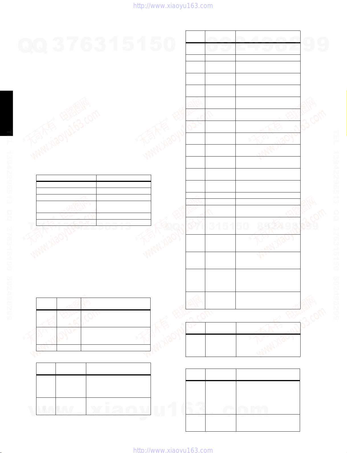
6.1 Errorlog
Explanation:
The application errors will be logged in the NVRAM. The
maximum number of error bytes that will be visible is 16. The
first word (4 digits) of the byte is the component identification,
the last word is the error code.
The diagnostics software will present a combination of this
component identification plus an error code on the local display
(and on the attached terminal). The last reported error is shown
as < 00000000, the oldest visible error as 00000000 > and the
errors in between as < 00000000 >.
The devices that may report errors are the serial controller
(UART), the basic engine (BE), the slave processor (SLPH),
the SACD Stream Manager (SSM) and the SACD Media
Access (SMA). The identification of these components is as
follows:
Component name Component identification
Serial controller (UART) 000A
Engine (BE) 0016
Slave Processor (SLPH) 001A
SACD Stream Manager
(SSM)
SACD Media Access (SMA) 002E
Diagnostic software (DS) Dxxx
TEL
The tables in the next chapters list the error code and
corresponding problem. The Explantion column has a more
detailed description and the most likely reason for the error.
Some Examples:
002E0000 (SMA reported a timeout error)
0016010A (Engine could not fully close or open the tray)
D0010001 (Flash checksum failed).
UART Error Codes
Error
Number
0000 BUF_OVE
0001 COMMUNI
0002 TIME OUT
BE Errors
Error
Number Error name Explanation
0101 S2B_ILL_CO
0102 S2B_ILL_PA RAMCommand not allowed in this
w
w
3
7
6
3
001C
1
13942296513
Error
name Explanation
RFLOW
CATION
MMAND
w
To many characters were offered in
too little time. Reason: system was
too busy doing other jobs.
Usually a protocol error. Reason:
bad connection between engine
and processor.
Parameter(s) not valid for this
command. Reason: some
communication problem
between UART and engine.
state or unknown. Reason: see
S2B_ILL_COMMAND error
.
xia
5
o
1
y
5
u
0
Q
1
Error
Number Error name Explanation
0103 S2B_SLEDGE Sledge could not be moved to
0104 S 2B_FO CUS Focus failure
0105 S2B_MOTOR Motor could not reach speed
0106 S 2B_RADIAL Servo didn't get on track after
0107 S2B_PLL_LOCKPLL could not lock in Accessing
0108 SBC_HEADE
0109 S2B_SBC_NO
010A S2B_TRAY Tray could not be opened or
010B S2B_TOC_READTOC could not be read within
010C S2B_JUMP Requested seek could not be
010D S2B_NON_EX
010E S2B_NON_EX
010F Speed setting A wrong or inappropraiate speed
0116 NO_DISC No disc selected
011A T RA Y_I NIT After reset, initialized tray
011B NO TOC INFO No TOC information in lead-in
01F0 S2B_OVERRUNToo many bytes received over
3
Q
01F1 S2B_COMM_TONot enough bytes are received
01F2 S2B_PARITY Byte received with parity error.
01F3 S2B_ILL_PHASECMD IDC is not valid,
01F4 S2B_ILL_NR_
SLPH Error Codes
Error
Number Error name Explanation
0000 COMMUNICA
SSM Error Codes
Error
Code Error name Explanation
0006 SP_SYNCER
6
0007 SP_EDCERRORData coming from disc is
6
7
3
9
8
R_TO
T_FOUND
IST_SES
IST_BCA
5
1
3
OF_BYTES
TION
ROR
.
c
4
2
home position.
within timeout
several retries.
or Tracking state
Header timeout
Requested subcode item could
not be found.
closed completely.
timeout period.
performed.
Attempt to access a non-existing
session.
Caller tries to acces a non-
existing BCA area
value has been set
area or erase TOC found
S2B Reason: see
5
1
S2B_ILL_COMMAND error
over S2B Reason: see
S2B_ILL_COMMAND error
Reason: see
S2B_ILL_COMMAND error
transmission out of sync.
Reason: see
S2B_ILL_COMMAND error
Byte count has an illegal value.
Reason: see
S2B_ILL_COMMAND error
Error in I2C communication.
Reason: bad connection
between slave processor and
main processor.
System cannot get synchronized
with sectors coming from disc.
Reason: Usually a damaged
disc or the player was dropped/
pushed during operation. If not,
the engine is malfunctioning.
o
damaged. Reason: see
SP_SYNCERROR
0
m
8
9
9
8
2
4
2
9
8
9
2
9
9
TEL 13942296513 QQ 376315150 892498299
9
18

DVD-C940/DV-C6680
Error
Code Error name Explanation
0008 SP_CONTINU
7
Q
Q
TEL 13942296513 QQ 376315150 892498299
3
0009 DMX_CONTI
000A LLD_ERROR An illegal audio format was
000B BCU_ERROR Internal problem in Furore chip
6.2 Trade Mode
When the player is in Trade Mode, the player cannot be
controlled by means of the front key buttons, but only by means
of the remote control.
TO ACTIVATE TRADE MODE
6
ITYERROR
NUITYERRO
R
POWER ON
Sequence of sectors coming
1
5
3
from disc is incorrect. Reason:
see SP_SYNCERROR
Sequence of sectors is incorrect.
Reason: problem with buffer
RAM
offered to the decoder. Reason:
unknown audio type on disc or
problem with buffer RAM
1
5
0
TO DEACTIVATE TRADE MODE
POWER ON
SMA Error Codes
Error
Number Error name Explanation
0000 SMA_TIMEO
8
9
UTERROR
2
4
9
Data coming from disc not in
time. Reason: damaged disc or
engine problem.
8
2
9
9
/DV-C6680
DVD-C940
TEL 13942296513 QQ 376315150 892498299
TEL
w
w
DURING STOP MODE AND W/O DISC.
PRESS REMOTE KEYS COMBINATION
<PLAY> <259> <PLAY>
PLAYER IS IN TRADE MODE WHEN
13942296513
PRESSING FRONT KEYS,
THE PLAYER DOESN'T RESPOND
Figure 37
Note: To activate and deactivate the Trade Mode with the disc
in the player, the procedure is similar to above, except that the
remote control keys combination is pressed at the instant when
the local display is flashing “READING”
■ SERVICE NOTE
This information is confidential and may not be distributed. Only a qualified service person should reprogram the
Mono board.
After reset of NV-memory or repair of the Mono board,
all of the customer settings and the region code will be
lost.
Reprogramming of the Mono board will install the default
factory settings and assigned region code.
Reprogramming is limited to 25 times.
When the counter reaches 25, reprogramming is no
longer possible.
Reprogramming is done by using the remote control.
w
.
xia
DURING STOP MODE AND W/O DISC.
PRESS REMOTE KEYS COMBINATION
<PLAY> <259> <PLAY>
PLAYER IS IN NORMAL MODE WHEN
THE PLAYER WILL RESPOND
o
y
Q
PRESSING FRONT KEYS,
u
1
Q
8
9
4
2
9
8
0
5
1
5
1
3
6
7
3
● Put the player in the stop mode with no disc loaded.
● Press the following keys on the remote control:
<PLAY> followed by numerical keys <2> <7> <4>
The display shows: “--- --- --“
● Now, successively press the following keys:
<1> <1> <1> <0> <1> <8> <0> <6>
● Press<PLAY> again.
The TV screen will momentarily become BLUE to
confirm that the mono board has been reprogrammed;
6
3
.
c
o
then the set goes to the stop mode.
m
2
9
9
19
DVD-C940/DV-C6680
■ IC DATA
7
Q
Q
DVD-C940
/DV-C6680
TEL 13942296513 QQ 376315150 892498299
TEL
3
DVDALAS2plus Advanced Analog DVD
Signal Processor and Laser Supply
DEVICE BLOCK DIAGRAM
OPU
Interface
13942296513
6
DVD
CD
3
1
5
MUX
MUX
1
5
Diode
Amplifiers
Processing
DPD
Push Pull
Offset
compensations
3 Beam
Tracking
0
Q
Q
Land/Groove
Swap
Mute
3
7
6
8
Var Gain
3
9
1
5
2
1
5
4
9
TZA1033
Balanced
HF
Data & header
Header
Land
Servo
Signals
D1-D6
8
0
9
8
2
4
2
9
8
9
2
9
9
TEL 13942296513 QQ 376315150 892498299
9
w
w
Rext
w
.
xia
V & I references
Dual Laser
Supply
Laser#1
Laser#2
TZA1033 Device Block Diagram (item 7100)
o
y
u
1
6
FTC comp.
Serial
I/Face
3
.
c
Control
Interface
o
FTC
m
20

DVD-C940/DV-C6680
DVDALAS2plus Advanced Analog DVD
Signal Processor and Laser Supply
7
Q
Q
TEL 13942296513 QQ 376315150 892498299
TEL
3
PIN COFIGURATION
handbook, full pagewidth
13942296513
6
CD-A
CD-B
CD-C
CD-D
CD-REF
CD-E
CD-F
VDDA1
VSSA1
DVD-MI
DVD-A
DVD-B
DVD-C
DVD-D
DVD-REF
3
-
1
1
2
3
4
5
6
7
8
9
10
11
12
13
14
15
16
5
DVD-LO
VDDL
64
63
1
CD-MI
62
61
5
CD-LO
R-EXT
60
0
VDDA2
VSSA2
59
58
Q
VSSA3
57
XXX
Q
RFN
RFP
56
55
TZA1033
7
3
8
VDDA3
RF-REF
54
53
3
6
9
-
52
1
---
51
5
2
50
1
5
49
4
0
48
O-A
47
O-B
46
O-C
45
O-D
44
VDDA4
43
VSSA4
42
S1
41
S2
40
O-CENTRAL
39
LPF-DPD2
38
LPF-DPD1
37
TD2
36
FTC-REF
35
TD1
TDO
34
8
FTC
33
TZA1033
8
9
2
9
4
2
9
8
9
2
9
9
9
/DV-C6680
DVD-C940
TEL 13942296513 QQ 376315150 892498299
17
18
19
20
21
22
23
24
25
26
27
28
29
COM
30
COO
VDDD5
-
TM
LAND
TZA1033 Pins (item 7100)
SIDA
VDDD3
HEADER
Pin configuration.
SICL
SILD
COP
VSSD
31
STB
NEW
32
MXXxxx
-
w
w
w
.
xia
o
y
u
1
6
3
.
c
o
m
21

DVD-C940/DV-C6680
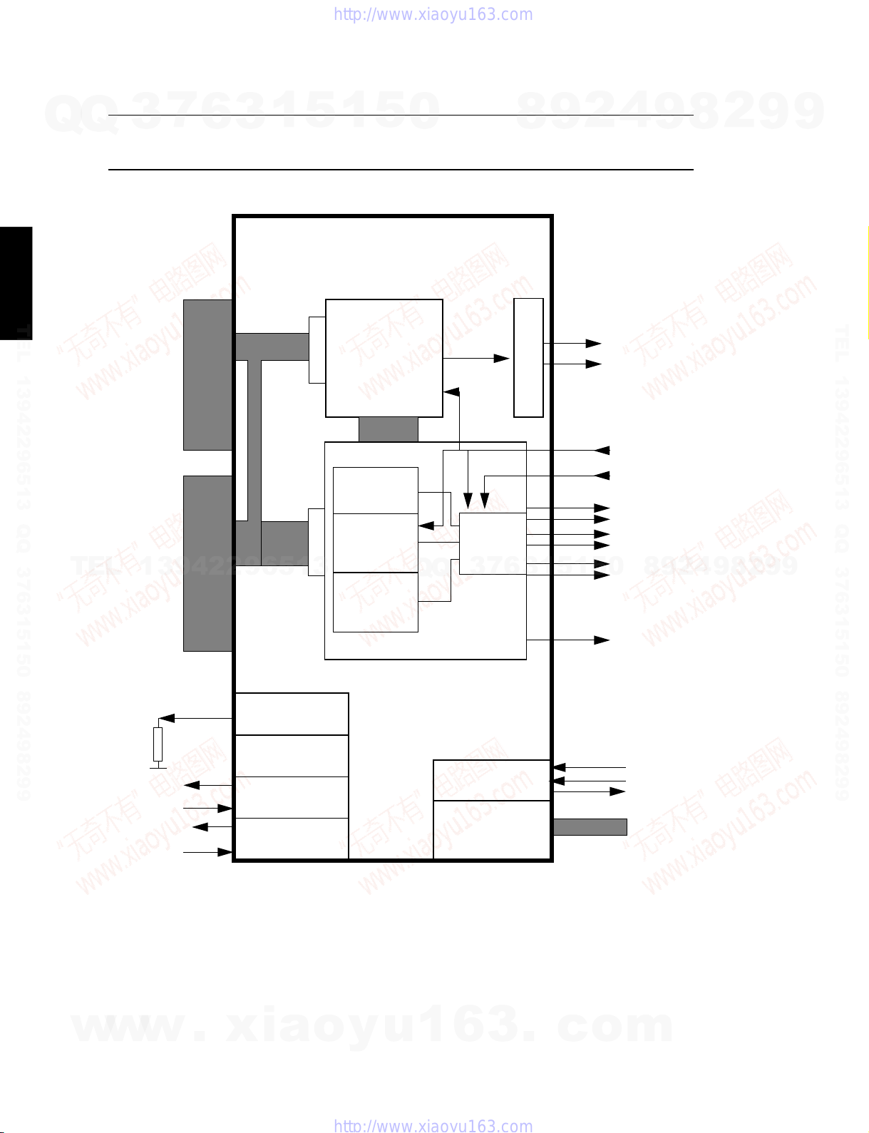
Front-end Processor
7
Q
Q
DVD-C940
/DV-C6680
TEL 13942296513 QQ 376315150 892498299
TEL
3
Diagram M2
Channel decoder
A/D
13942296513
6
Bit Detector
& Demodulator
Motor/
Tacho interface
A/D
A/D
3
1
CD/DVD Erco
Memory Proc
PCS
accelerator
servo
accelerator
5
servo
processor
1
Servo
RAM
5
control
registers
0
Block decoder/
encoder
interface
Q
drive
interface
subcode
interface
Q
3
7
Erco
µP
address
decoder
1k5 aux
RAM
6
SFRs
8
DRAM interface
cpu interface
1
3
2
9
Memory Proc
5
1
5
SAA7812HL
4
9
Host
interface
multimedia
interface
DAC
CSS
module
cpu
1k5 ROM
736 RAM
2
9
8
0
port regs
8
4
2
9
8
9
2
9
9
TEL 13942296513 QQ 376315150 892498299
9
w
w
w
.
xia
o
Functional Block Diagram
SAA7812HL Block Diagram (item 7200)
y
u
1
6
3
.
c
o
m
22

DVD-C940/DV-C6680
Front-end Processor
7
Q
Q
TEL 13942296513 QQ 376315150 892498299
TEL
3
VDD3P1
3P1
V
SS
T1
T2
T3
DAC_RP
DAC_RN
DAC_VPOS
DAC_VNEG
DAC_LP
DAC_LN
TEST1
TEST2
CRIN
CROUT
A1
V
DD
A1
V
SS
HFIN_DN
HFIN_DP
HFIN_SE
VCOM
IREF
WREFLO
TEST3
A2
V
SS
A2
V
DD
SIN_PHI
COS_PHI
TEST4
13942296513
XDET(auxadc)
ACT_EMFP
ACT_EMFN
TEST5
TEST6
TEST7
UOPB
UOPT
ALPHA0
A3
V
SS
V
A3
DD
D1
D2_TLN
D3_REN
D4_FEN
S1_MIRN
S2
VRIN
FTCH
P5_7_DEFO_N
P5_6_DEFI_N
P5_5_TL
P5_4_RP_FOK
6
BCA
MOTO1
207
208
1
2
3
4
5
6
7
8
9
10
11
12
13
14
15
16
17
18
19
20
21
22
23
24
25
26
27
28
29
30
31
32
33
34
35
36
37
38
39
40
41
42
43
44
45
46
47
48
49
50
51
52
5354555657585960616263646566676869707172737475767778798081828384858687888990919293949596979899
3
TEST10
POR_NEG
205
206
TEST9
204
TEST8
203
1
vampire3
vampire4
vampire5
200
201
202
5
3C4
SS
vampire2
V
198
199
3C4
DD
V
197
1
IECO_CL1
vampire1
195
196
3P8
V
194
DD
3P8
SS
V
193
5
0
XDD6
XDD7
XDD8
XDD9
XDD10
XDD11
XDD12
XDD13
XDD14
XDD15
183
184
185
186
187
188
189
190
191
192
SAA7812 M3x
Iguana
Q
Q
3
XDD5
182
XDD4
181
7
XDD3
180
XDD2
179
6
8
XDD0
XDD1
177
178
3
3P7
SS
V
176
1
9
XCAS_LO
XWR
XDA10
173
174
175
5
2
XCAS_HI
172
1
XRAS
171
5
3C3
SS
V
170
3C3
DD
V
169
0
4
XDA8
XDA9
167
168
SAA7812HL
8
9
XDA2
XDA3
XDA4
XDA5
XDA6
XDA7
161
162
163
164
165
166
2
9
8
100
4
XDA1
160
101
2
3P6
XDA0
V
158
159
9
102
103
SS
3P6
V
8
104 157
DD
156
155
154
153
152
151
150
149
148
147
146
145
144
143
142
141
140
139
138
137
136
135
134
133
132
131
130
129
128
2
127
126
125
124
123
122
121
120
119
118
117
116
115
114
113
112
111
110
109
108
107
106
105
9
9
9
DASP
CS1
CS0
V
5P1
SS
V
5P1
DD
DA2_GRD
DA0
PDIAG
DA1_GWR
IOCS16
INTRQ
DMACK_GRQ
IORDY
DIOR
DIOW
DMARQ_GACK
V
5P2
SS
V
5P2
DD
DD15
DD0
DD14
DD1
DD13
DD2
DD12
DD3
DD11
DD4
DD10
9
DD5
DD9
DD6
DD8
DD7
5P3
V
SS
V
5P3
DD
HRESET
P3_0_RXD1
P3_1_TXD1
P3_2_INT0
P3_3_INT1
V
3P5
SS
V
3P5
DD
P3_4_RXD2
P3_5_TXD2
P3_6_WRN
P3_7_RDN
UDA7
UDA6
UDA5
UDA4
UDA3
/DV-C6680
DVD-C940
TEL 13942296513 QQ 376315150 892498299
w
w
w
P5_3_CE1
P5_2_CLO
P5_1_SDA
.
xia
SL
FO
RA
P5_0_SCL
3P2
3P2
SS
DD
V
V
REF_SIN
RAC_SW
REF_COS
3C1
3C1
SS
DD
V
V
P4_4_PXT
P4_6_PXT2
P4_5_PXT0
P4_7_PXT2EN
UA15
UA14
UA13
P4_3_A19
P4_2_A18
P4_1_A17
UA12
P4_0_A16
3P3
3P3
UA9
UA8
UA11
UA10
SS
DD
V
V
EAN_WAITN
3C2
3C2
SS
DD
SCCLK
V
V
UA7_P1_7
UA6_P1_6
UA5_P1_5
PSENN_CS
ALE_ASTB
DSDEN_SRST
UA4_P1_4
3P4
3P4
SS
UDA0
UDA1
UDA2
DD
V
V
UA3_P1_3
UA2_P1_2
UA1_P1_1
UA0_P1_0
Pin Diagram
SAA7812HL Pins (item 7200)
o
y
u
1
6
3
.
c
o
m
23
 Loading...