

Page 1
DRUM TRIGGER MODULE
Owner’s Manual
Page 2
SPECIAL MESSAGE SECTION
This product utilizes batteries or an external power supply (adapter).
DO NOT connect this product to any power supply or adapter other
than one described in the manual, on the name plate, or specifically
recommended by Yamaha.
WARNING: Do not place this product in a position where anyone could
walk on, trip over ,or roll anything over power or connecting cords of any
kind. The use of an extension cord is not recommended! IF you must use
an extension cord, the minimum wire size for a 25' cord (or less ) is 18
AWG. NOTE: The smaller the AWG number ,the larger the current
handling capacity. For longer extension cords, consult a local electrician.
This product should be used only with the components supplied or; a
cart, rack, or stand that is recommended by Yamaha. If a cart, etc., is
used, please observe all safety markings and instructions that accompany the accessory product.
SPECIFICATIONS SUBJECT TO CHANGE:
The information contained in this manual is believed to be correct at the
time of printing. However, Yamaha reserves the right to change or
modify any of the specifications without notice or obligation to update
existing units.
This product, either alone or in combination with an amplifier and headphones or speaker/s, may be capable of producing sound levels that
could cause permanent hearing loss. DO NOT operate for long periods
of time at a high volume level or at a level that is uncomfortable. If you
experience any hearing loss or ringing in the ears, you should consult
an audiologist.
IMPORTANT: The louder the sound, the shorter the time period before
damage occurs.
Some Yamaha products may have benches and / or accessory mounting
fixtures that are either supplied with the product or as optional accessories. Some of these items are designed to be dealer assembled or
installed. Please make sure that benches are stable and any optional
fixtures (where applicable) are well secured BEFORE using.
Benches supplied by Yamaha are designed for seating only. No other
uses are recommended.
NOTICE:
Service charges incurred due to a lack of knowledge relating to how a
function or effect works (when the unit is operating as designed) are not
covered by the manufacturer’s warranty, and are therefore the owners
responsibility. Please study this manual carefully and consult your
dealer before requesting service.
ENVIRONMENTAL ISSUES:
Yamaha strives to produce products that are both user safe and environmentally friendly. We sincerely believe that our products and the
production methods used to produce them, meet these goals. In keeping with both the letter and the spirit of the law, we want you to be
aware of the following:
Battery Notice:
This product MAY contain a small non-rechargeable battery which (if
applicable) is soldered in place. The average life span of this type of
battery is approximately five years. When replacement becomes
necessary, contact a qualified service representative to perform the
replacement.
This product may also use “household” type batteries. Some of these
may be rechargeable. Make sure that the battery being charged is a
rechargeable type and that the charger is intended for the battery
being charged.
When installing batteries, do not mix batteries with new, or with batteries of a different type. Batteries MUST be installed correctly. Mismatches or incorrect installation may result in overheating and battery
case rupture.
Warning:
Do not attempt to disassemble, or incinerate any battery. Keep all
batteries away from children. Dispose of used batteries promptly and
as regulated by the laws in your area. Note: Check with any retailer of
household type batteries in your area for battery disposal information.
Disposal Notice:
Should this product become damaged beyond repair, or for some
reason its useful life is considered to be at an end, please observe all
local, state, and federal regulations that relate to the disposal of products that contain lead, batteries, plastics, etc. If your dealer is unable
to assist you, please contact Yamaha directly.
NAME PLATE LOCATION:
The name plate is located on the top panel of the product. The name
plate lists the product’s model number, power requirements, and other
information. The serial number is located on the rear panel. Please
record the model number, serial number, and date of purchase in the
spaces provided below, and keep this manual as a permanent record of
your purchase.
Model
Serial No.
Purchase Date
92-BP (others)
PLEASE KEEP THIS MANUAL
NEDERLAND / THE NETHERLANDS
• Dit apparaat bevat een lithium batterij voor geheugen back-up.
• This apparatus contains a lithium battery for memory back-up.
• Raadpleeg uw leverancier over de verwijdering van de batterij op
het moment dat u het apparaat ann het einde van de levensduur
afdankt of de volgende Yamaha Service Afdeiing:
Yamaha Music Nederland Service Afdeiing
Kanaalweg 18-G, 3526 KL UTRECHT
Tel. 030-2828425
• For the removal of the battery at the moment of the disposal at the
end of the service life please consult your retailer or Yamaha
Service Center as follows:
Yamaha Music Nederland Service Center
Address : Kanaalweg 18-G, 3526 KL UTRECHT
Tel : 030-2828425
• Gooi de batterij niet weg, maar lever hem in als KCA.
• Do not throw away the battery. Instead, hand it in as small chemical
waste.
(lithium disposal)
ADVARSEL!
Lithiumbatteri—Eksplosionsfare ved fejlagtig håndtering. Udskiftning
må kun ske med batteri af samme fabrikat og type. Levér det brugte
batteri tilbage til leverandoren.
VARNING
Explosionsfara vid felaktigt batteribyte. Använd samma batterityp
eller en ekvivalent typ som rekommenderas av apparattillverkaren.
Kassera använt batteri enlight fabrikantens instruktion.
VAROITUS
Paristo voi räjähtää, jos se on virheellisesti asennettu. Vaihda
paristo ainoastaan laitevalmistajan suosittelemaan tyyppiin. Hävitä
käytetty paristo valmistajan ohjeiden mukaisesti.
(lithium caution)
Caution
Always use the supplied Yamaha AC Adaptor to power DTXPRESS.
The use of an incompatible adaptor may cause a serious shock
hazard.
Page 3
PRECAUTIONS
PLEASE READ CAREFULLY BEFORE PROCEEDING
* Please keep these precautions in a safe place for future reference.
WARNING
Always follow the basic precautions listed below to avoid the possibility of serious injury or even death from electrical shock,
short-circuiting, damages, fire or other hazards. These precautions include, but are not limited to, the following:
• Do not open the instrument or attempt to disassemble the internal parts or
modify them in any way. The instrument contains no user-serviceable parts. If
it should appear to be malfunctioning, discontinue use immediately and have it
inspected by qualified Yamaha service personnel.
• Do not expose the instrument to rain, use it near water or in damp or wet
conditions, or place containers on it containing liquids which might spill into
any openings.
• If the AC adaptor cord or plug becomes frayed or damaged, or if there is a
sudden loss of sound during use of the instrument, or if any unusual smells or
smoke should appear to be caused by it, immediately turn off the power switch,
disconnect the adaptor plug from the outlet, and have the instrument inspected
by qualified Yamaha service personnel.
• Use the specified adaptor (PA-3B or an equivalent recommended by Yamaha)
only. Using the wrong adaptor can result in damage to the instrument or
overheating.
• Before cleaning the instrument, always remove the electric plug from the outlet.
Never insert or remove an electric plug with wet hands.
• Check the electric plug periodically and remove any dirt or dust which may
have accumulated on it.
CAUTION
Always follow the basic precautions listed below to avoid the possibility of physical injury to you or others, or damage to the
instrument or other property. These precautions include, but are not limited to, the following:
• Do not place the AC adaptor cord near heat sources such as heaters or radiators,
and do not excessively bend or otherwise damage the cord, place heavy objects
on it, or place it in a position where anyone could walk on, trip over, or roll
anything over it.
• When removing the electric plug from the instrument or an outlet, always hold
the plug itself and not the cord.
• Do not connect the instrument to an electrical outlet using a multiple-connector.
Doing so can result in lower sound quality, or possibly cause overheating in
the outlet.
• Unplug the AC power adaptor when not using the instrument, or during electrical
storms.
• Before connecting the instrument to other electronic components, turn off the
power for all components. Before turning the power on or off for all components,
set all volume levels to minimum. Also, be sure to set the volumes of all
components at their minimum levels and gradually raise the volume controls
while playing the instrument to set the desired listening level.
• Do not expose the instrument to excessive dust or vibrations, or extreme cold
or heat (such as in direct sunlight, near a heater, or in a car during the day) to
prevent the possibility of panel disfiguration or damage to the internal
components.
•Do not use the instrument near other electrical products such as televisions,
radios, or speakers, since this might cause interference which can affect proper
operation of the other products.
• Do not place the instrument in an unstable position where it might accidentally
fall over.
• Before moving the instrument, remove all connected adaptor and other cables.
• When cleaning the instrument, use a soft, dry cloth. Do not use paint thinners,
solvents, cleaning fluids, or chemical-impregnated wiping cloths. Also, do not
place vinyl, plastic or rubber objects on the instrument, since this might discolor
the panel or keyboard.
• Do not rest your weight on, or place heavy objects on the instrument, and do
not use excessive force on the buttons, switches or connectors.
• Use only the stand/rack specified for the instrument. When attaching the stand
or rack, use the provided screws only. Failure to do so could cause damage to
the internal components or result in the instrument falling over.
• Do not operate the instrument for a long period of time at a high or uncomfortable
volume level, since this can cause permanent hearing loss. If you experience
any hearing loss or ringing in the ears, consult a physician.
■ REPLACING THE BACKUP BATTERY
• This instrument contains a non rechargeable internal backup battery which
permits internal data to remain stored even when the power is off. When the
backup battery needs replacing, the message "Battery Low" will display in the
display. When this happens, immediately back up your data using an external
device such as the floppy disk-based Yamaha MIDI Data Filer MDF3, then
have qualified Yamaha service personnel replace the backup battery.
• Do not attempt to replace the backup battery yourself, in order to prevent the
possible serious hazards. Always have qualified Yamaha service personnel
replace the backup battery.
• Never place the backup battery in a location that a child can reach, since a child
might accidentally swallow the battery. If this should happen, consult a physician
immediately.
■ SAVING USER DATA
• Save all data to an external device such as the Yamaha MIDI Data Filer MDF3,
in order to help prevent the loss of important data due to a malfunction or user
operating error.
Yamaha cannot be held responsible for damage caused by improper use
or modifications to the instrument, or data that is lost or destroyed.
Always turn the power off when the instrument is not in use.
(3)-4
Page 4
Thank you for purchasing the YAMAHA DTXPRESS.
The DTXPRESS is a compact drum trigger module that is equipped with
an AWM tone generator and sequencer functions.
To g et the most out of your DTXPRESS, please read this manual carefully.
Also, after reading, keep this manual in a safe place for future reference.
How to use the Manual
The DTXPRESS Owner’s Manual is divided into the following two sections.
● Basic Guide (P. 2-26)
Please read this section before using the DTXPRESS.
This section contains cautions that must be followed for safe and proper use of the DTXPRESS.
Also, control and function names, connecting the pads and how to play the DTXPRESS, how to record and playback
songs, how to create original drum kits are all described in this section.
● Reference (P. 27-61)
This section describes in detail each of the DTXPRESS’ functions.
● Appendix (P. 63-)
At the rear of this book you will find an appendix section with specifications, error messages, drum voice, song, MIDI data
format, etc. .
About the descriptions
This manual describes buttons and explanations using the following rules.
• [PLAY], [START/S], etc. The button on the front panel is indicated with [ ]. (brackets).
• [SHIFT]+[START/S], etc. Means hold the [SHIFT] button and press the [START/S] button.
•[PAGEs]/[PAGEt], etc. Means use the [PAGEs] button or [PAGEt] button.
•“Complete!”, etc. Words inside “ ” indicate the message shown on the display.
• m P. 10, etc. Indicates the reference page where further information can be found.
NOTE
The illustrations and LCD screens as shown in this owner’s manual are for instructional purposes only, and
may appear somewhat different from those on your instrument.
Inside this package
This package contains the following items. After opening the package, please check and makes sure that all the items In the
list are present.
• The DTXPRESS
•Power Adaptor
• Owner’s Manual (this book)
4
Page 5

DTXPRESS Main Features
Along with the drum trigger function found in the DTXPRESS’ compact half-rack 1U size body is a 32 voice
polyphonic tone generator compatible with the GM System Level 1 standard and 2-track sequencer all especially designed for drummers.
You can use the DTXPRESS in many situations such as live performance, rhythm practice, original song
creation and recording.
■ Drum Trigger Function
• 10 trigger input jacks and a hi-hat controller input jack are provided. Besides trigger pads you can also use Yamaha’s DT10
Drum Triggers, etc. Stereo type pads are also compatible.
• Setup data for the connected pads, such as trigger input types,
sensitivity, etc., consists of 7 preset patterns. A user area also
provides 4 patterns.
• 48 preset drum kits as well as memory space for 32 user drum
kits.
■ Tone Generator Section
•A high-quality 16-bit AWM2 (PCM) tone generator that complies with the GM System Level 1 standard. 32 voice polyphonic.
•A total of 910 drum and percussion voices as well as 128 keyboard voices that comply to the GM System Level 1.
• An internal digital reverb section that is the same as found in
Yamaha’s MU Series of GM/XG tone generators.
• User drum kits use a single drum map that can be edited freely.
■ Sequencer Section
•A 2-track sequencer for recording songs. Each track can contain data for MIDI channels 1-16.
•A total of 95 preset songs as well as a User Song Area that provides memory space for 32 original user songs.
• In addition to one main song that is controlled from the panel
and with MIDI, 3 pad songs can be individually controlled and
simultaneously played by trigger input from the pads.
•Pad songs can be played one measure at a time, each measure
triggered with a stroke on a pad.
• Record your performance in real-time along with sequencer data
from an external device.
• Easily mute the song’s drum part or a specified drum voice and
play along with the song.
• Playback in sync with an external sequencer is possible.
•Groove Check Function checks and provides instant feedback
on your rhythmic skills offering a great way to improve your
technique.
■ Interface
• Equipped with both MIDI IN/OUT jacks and a TO HOST jack.
Connect the DTXPRESS to external MIDI devices or a computer to expand your system.
•The TO HOST jack and HOST SELECT switch provides direct
connection to a computer.
• Connect a CD or MD player, etc. to the AUX IN jack and play
along with your favorite recordings.
• Equipped with a headphone jack.
GM
“GM” (General MIDI) is a standard that provides common formats for tones to ease the transmission of MIDI song
data and provide the compatibility to playback the original tones when tone generators by different manufacturers
and of different types are used.
5
Page 6

CONTENTS
Basic Guide
PRECAUTIONS ........................................ 3
How to use the Manual ........................... 4
About the descriptions ........................... 4
Inside this package ................................. 4
DTXPRESS Main Features ...................... 5
Controls and Functions .......................... 8
Front Panel ................................................. 8
Rear Panel .................................................. 9
Setting Up .............................................. 10
■ Connecting the pads ............................. 10
Setting up with Acoustic Drums ................ 11
■ Connecting a Mixer or Audio
Equipment............................................ 12
■ Connecting a MIDI Device .................... 12
■ Connecting a Computer ........................ 12
■ Connecting a CD Player, etc.
(AUX IN jack) ....................................... 13
■ Connecting a Pair of Headphones
(PHONES jack) .................................... 13
■ Connecting the Power Supply............... 13
The DTXPRESS Quick Guide
(Basic Functions List) ........................... 14
Play the DTXPRESS! ............................. 16
Play Along with the Metronome ........... 17
Play Along with a Song ........................ 18
Record Your Performance ..................... 20
Create Your Own Original Drum Kit ..... 22
Getting More Out of Your DTXPRESS .....
■ Factory Set ........................................... 24
■ Functions related to connections and
input source (pads) .............................. 24
■ Set the Reverb ...................................... 24
■ Settings related to the Drum Voice ....... 24
Settings Related to the Tone Generator ...
■
■ Settings Related to the Song ................ 25
■ Other Functions .................................... 25
■ Using MIDI ............................................ 25
■ Connecting a Computer ........................ 26
24
25
Reference
DTXPRESS Internal Makeup ................ 28
Drum Kit Play Mode .............................. 30
1. Drum Kit & Song .......................................... 30
2. Trigger Setup & Tempo ................................. 30
3. Song & Mute ................................................. 31
Groove Check Function ................................... 31
About the Song ..................................... 32
Song Playback.................................................. 32
Song Recording ............................................... 34
Trigger Setup Edit Mode ....................... 35
1. INPUT Parameters ........................................ 36
1-1. Pad Type ......................................................... 36
1-2. Gain, Minimum Velocity .................................. 36
1-3. Velocity Curve ................................................. 37
1-4. Self Rejection, Rejection ................................ 37
1-5. Specific Rejection ........................................... 37
1-6. Trigger Setup Copy ......................................... 37
2. COMMON PARAMETERS ............................. 38
2-1. Increment/Decrement ..................................... 38
2-2. Input Exchange ............................................... 38
2-3. Trigger Setup Name ........................................ 38
Drum Kit Voice Edit Mode..................... 39
1. Voice Parameters.......................................... 40
1-1. Voice ............................................................... 41
1-2. Volume, Pan.................................................... 41
1-3. Tuning ............................................................. 41
1-4. Layer Balance ................................................. 42
1-5. Decay, Cutoff Frequency ................................ 42
1-6. Note Number .................................................. 42
1-7. Channel, Gate Time ........................................ 42
2. Input Common Parameters ......................... 43
2-1. Cross Fade ..................................................... 43
2-2. Reverb Send ................................................... 43
2-3. Alternate Group, Key Assign Mode ................ 43
2-4. Hold Mode ...................................................... 44
2-5. Key Off Enable ................................................ 44
2-6. Function .......................................................... 44
2-7. Pad Song ........................................................ 44
2-8. Rim To Pad ..................................................... 45
3. Reverb Parameter ......................................... 45
3-1. Reverb Type, Time .......................................... 45
3-2. Reverb Master Return .................................... 45
6
Page 7

4. Setup ............................................................. 46
4-1. Program Change, Bank Select ....................... 46
4-2. Volume, Pan .................................................... 46
4-3. Drum Kit Voice Copy....................................... 46
5. Drum Kit Common Parameters ................... 47
5-1. Volume ............................................................ 47
5-2. Drum Reverb Send ......................................... 47
5-3. Hi-hat Sensitivity ............................................. 47
5-4. Song Select .................................................... 47
5-5. Drum Kit Name ............................................... 47
Song Job Mode ..................................... 48
1. Tempo, Repeat Playback ................................... 48
2. Program Change, Bank Select .......................... 48
3. Volume, Pan ....................................................... 49
4. Song Copy ......................................................... 49
5. Quantize ............................................................ 49
6. Clear Track ......................................................... 50
7. Merge Track ....................................................... 50
8. Clear Song ......................................................... 50
9. Song Name ........................................................ 50
Utility Mode ............................................ 51
1. SYSTEM Group............................................. 52
1-1. Learn Mode .................................................... 52
1-2. Trigger Bypass ................................................ 52
1-3. Volume Mode .................................................. 52
1-4. Jump to Recent Page ..................................... 52
1-5. Hi-Hat Offset ................................................... 53
1-6. Factory Set ..................................................... 53
2. MIDI Group .................................................... 53
2-1. Bulk dump....................................................... 53
2-2. Channel 10 Program Change/Channel Event
Receive .......................................................... 54
2-3. Receive Program Change/System
Exclusive Messages....................................... 54
2-4. Program Change Table ................................... 55
2-5. MIDI Mode ...................................................... 55
2-6. Device Number, Local Control ........................ 55
2-7. MIDI Merge ..................................................... 55
2-8. Dump Interval ................................................. 56
2-9. Send Hi-Hat Control ....................................... 56
2-10. Host Thru Port .............................................. 56
3. Sequencer Group ......................................... 56
3-1. Click Voice ...................................................... 56
3-2. Click Tune ....................................................... 57
3-3. Click Note Number ......................................... 57
3-4. MIDI Control ................................................... 57
3-5. Count Switch .................................................. 57
3-6. Sync Mode ...................................................... 57
3-7. Use Tempo...................................................... 58
3-8. Click Mode ...................................................... 58
4. TG (Tone Generator) Group ......................... 58
4-1. Equalizer (EQ) ................................................ 58
4-2. Tuning ............................................................. 58
4-3. Volume ............................................................ 58
4-4. Reverb Bypass ............................................... 59
5. MAP (Drum Map) Group............................... 59
5-1. Voice ............................................................... 59
5-2. Volume, Pan.................................................... 60
5-3. Tuning ............................................................. 60
5-4. Layer Balance ................................................. 60
5-5. Decay, Cutoff Frequency ............................... 60
5-6. Reverb Send ................................................... 60
5-7. Alternate Group, Key Assign Mode ................ 61
5-8. Key Off Enable ................................................ 61
5-9. Map Copy ....................................................... 61
Appendix
Specifications ........................................ 64
Error Messages ..................................... 65
Trouble shooting ................................... 66
Drum Voice List ..................................... 68
GM Keyboard Voice List........................ 72
Preset Drum Kit List.............................. 72
Preset Song List .................................... 79
Trigger Setup List .................................. 79
MIDI Data Format................................... 80
MIDI Implementation Chart ................... 82
Index ....................................................... 83
Blank Chart ............................................ 85
7
Page 8
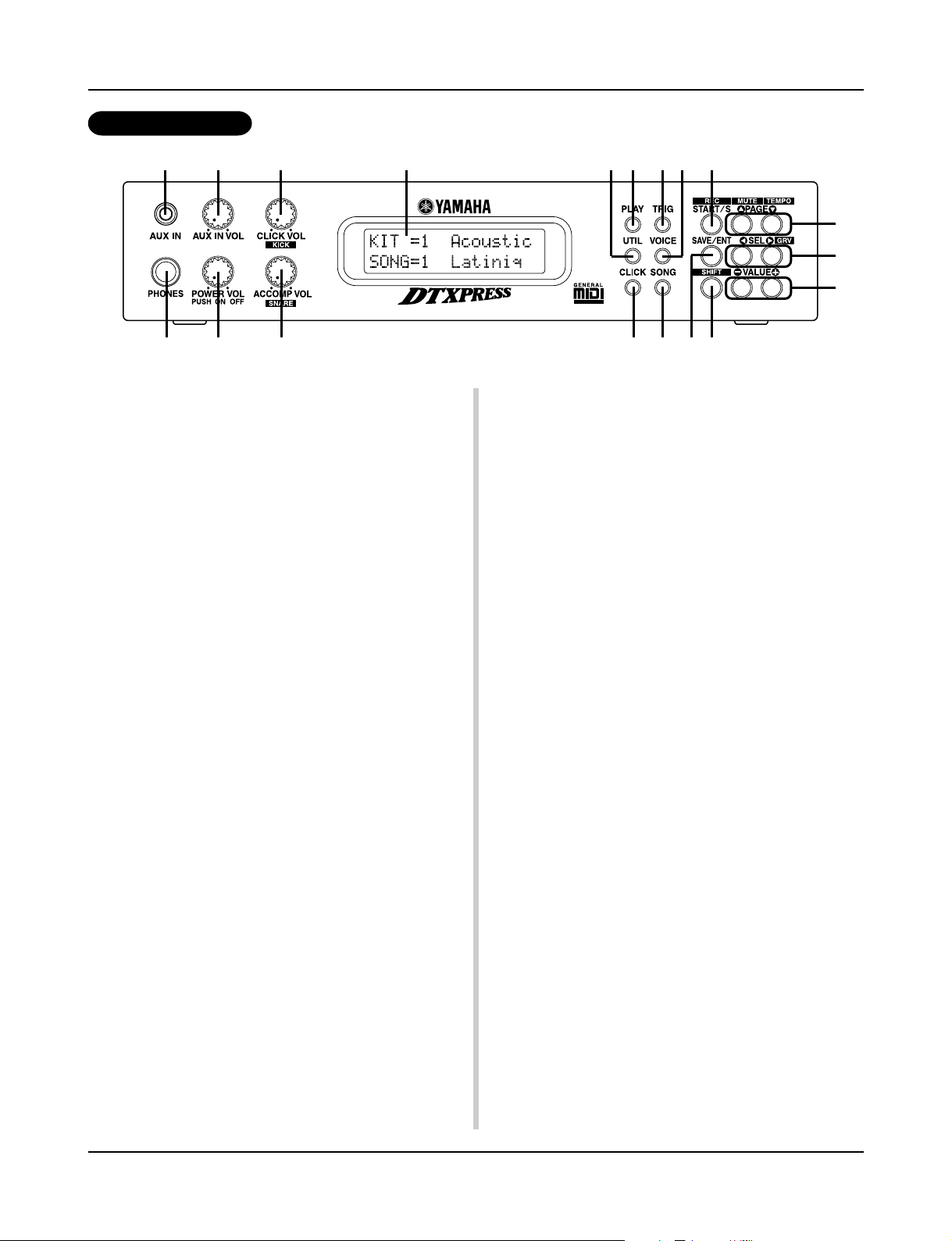
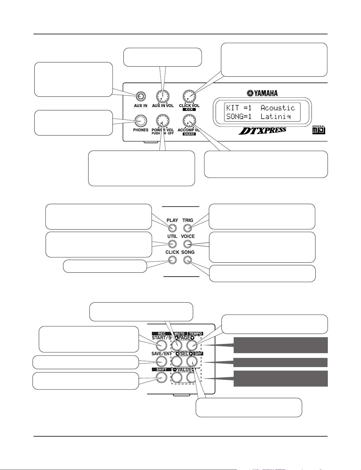
Controls and Functions
Front Panel
q w
e r
t u
y
q AUX IN Jack
Connect the output of an external audio device, etc., to this jack
(stereo mini jack). (P. 13)
This is convenient for playing along with music from a CD or
cassette player.
w AUX IN Volume (AUX IN VOL)
This volume control adjusts the volume of a CD or cassette player
connected to the AUX IN jack q.
e Head Phone Jack (PHONES)
Connect a pair of headphones to this jack to monitor the
DTXPRESS. (P. 13)
r Power Switch/Master Volume
(POWER/VOL)
Switches the power ON/OFF and controls the overall volume level
(output from the OUTPUT jacks and PHONES jack) of the
DTXPRESS.
Rotate the knob clockwise to increase volume, counter-clockwise
to decrease volume. Push the button to switch the power ON/OFF.
t Click Volume (CLICK VOL)
This volume control adjusts the volume of the metronome’s click.
(P. 17)
Holding the [SHIFT] button and rotating the knob adjusts the volume of the bass drum.
i
o !2
!1 !4
!7
!8
!9
!0
!3
!5 !6
o Utility Button (UTIL)
Press the button to enter the Utility Mode that contains basic settings for operation of the DTXPRESS.
!0 Click Button (CLICK)
Press this button to start/stop the metronome (click sound). (P. 17)
!1 Trigger Button (TRIG)
Press this button to enter the Trigger Setup Edit Mode. Doubleclick the button to display the “Gain, Minimum Velocity” page of
the Trigger Setup Edit Mode.
!2 Voice Button (VOICE)
Press this button to enter the Drum Kit Voice Edit Mode.
Press the button while in the Drum Kit Edit Mode allows you to
listen to the voice currently being set as if it where triggered from
the pad (audition function).
Double-click the button to display the “Volume, Pan” page of the
Drum Kit Voice Edit Mode.
Hold the [SHIFT] button and press the [VOICE] button to mute
audio output from the OUTPUT JACK @7 and PHONES JACK
e.
!3 Song Button (SONG)
Press this button to enter the Song Job Mode.
Double-click the button to display the “Clear Song” page of the
Song Job Mode.
y Accompaniment Volume (ACCOMP VOL)
This volume control adjusts the volume of the song’s accompaniment. (P. 18)
Holding the [SHIFT] button and rotating the knob adjusts the volume of the snare drum.
u LCD Display
The LCD Display shows information and data that is necessary to
operate the DTXPRESS.
i Play Button (PLAY)
Press the button to enter the DTXPRESS’ Drum Kit Play Mode.
8
!4 Start/Stop Button (START/S)
This button starts/stops playback or recording of the song.
Hold the [SHIFT] button and press [START/S] puts the
DTXPRESS in recording standby mode.
!5 Save/Enter Button (SAVE/ENT)
Carries out (enter) the command or save operation.
!6 Shift Button (SHIFT)
Holding this button and pressing another specific button switches
the button to its secondary function.
Page 9
Controls and Functions
!7 Page Button [PAGEs, PAGEt]
These buttons are used to navigate through the display pages. The
[PAGEs] button moves to the next page while the [PAGEt] button moves to the previous.
Hold the button to continuously move through the pages. Hold the
[SHIFT] button and press the [PAGEs] button to mute the drum
voice during playback (Rhythm Mute Function).
Hold the [SHIFT] button and press the [PAGEt] button to display the Song Tempo Setting (P. 18)
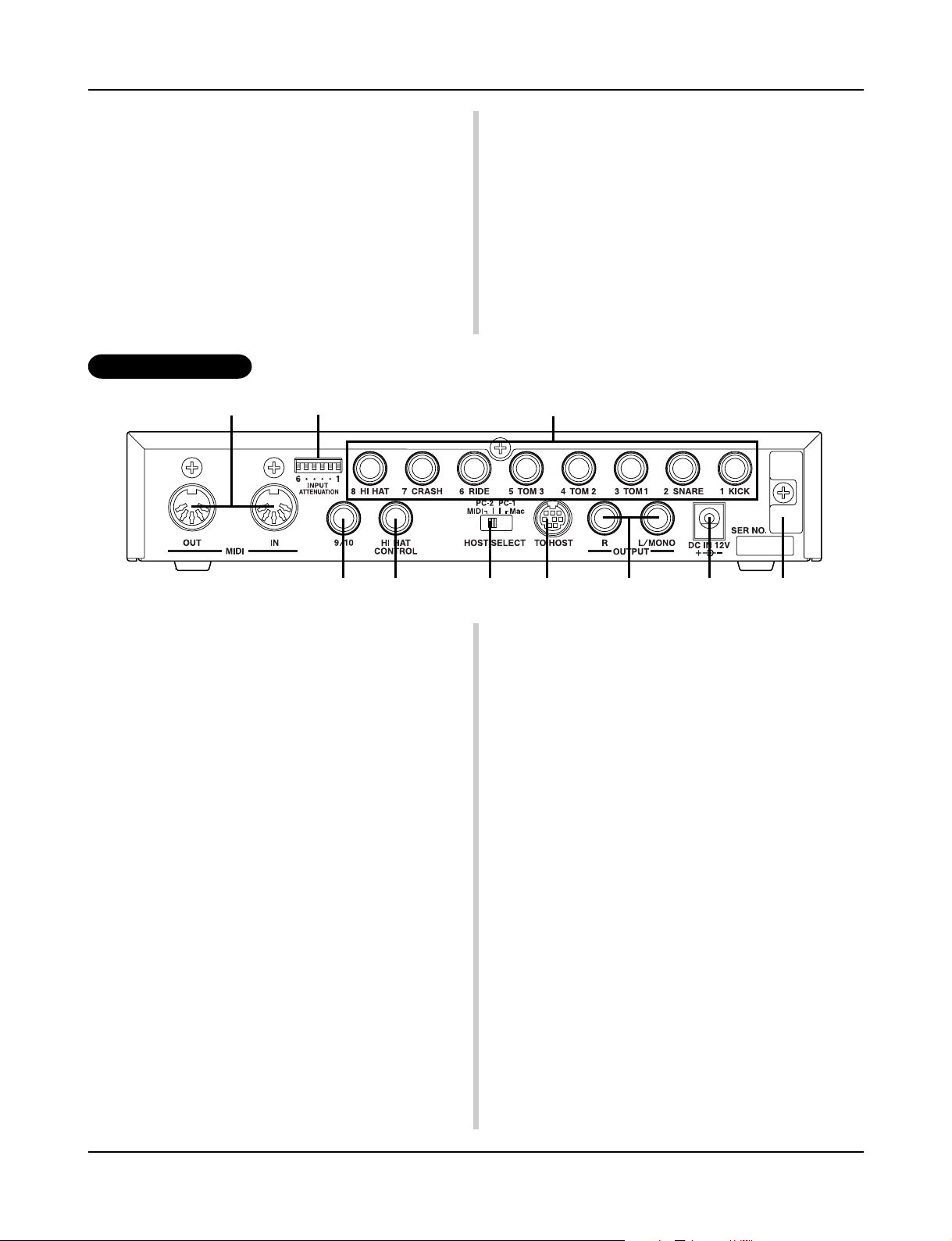
Rear Panel
@0 @1
H
L
!8 Select Button [SEL<, SEL>]
Use these buttons to move the cursor.
Hold the [SHIFT] button and press the [SEL>] button to switch
to the “Groove Check Function”. (P. 17)
!9 Value Button (VALUE–, VALUE+)
Changes the data value selected with the cursor.
Hold the button to continuously change the value.
Hold the [VALUE+] button and press the [VALUE–] button to
increase the value by 10 continuously.
Hold the [VALUE–] button and press the [VALUE+] button to
decrease the value by 10 continuously.
@2
@3
@4 @5 @6 @7 @8 @9
@0 MIDI IN/OUT Jack
These jacks are for the transmission and reception of MIDI data to
and from external MIDI devices.
Connecting external MIDI devices will expand the function of the
DTXPRESS.
@1 Input Attenuation Switch
(INPUT ATTENUATION)
Sets the general Input Attenuation for each Trigger Input Jack (1
KICK-6 RIDE). Lowering the switch (L) lowers the attenuation.
Raising the switch (H) increases attenuation. This adjusts the input level to meet the specification of pads and trigger sensors connected to the DTXPRESS. (P. 10)
@2 Trigger Input Jack (1 KICK-8HI HAT)
Connect pads and trigger sensors to these jacks. Connect pads according to the indication below each input. (P. 10) Stereo output
pads are also compatible with the DTXPRESS.
@3 Trigger Input Jack (9/10)
Used to connect a pad to the DTXPRESS. The stereo jack’s L
corresponds to input 9, R corresponds to input 10. Using a stereo
phone plug to connect two pads makes two-trigger input possible.
If a monaural phone plug is used, only input 9 is available for use.
@5 Host Select Switch
(HOST SELECT Mac/PC-1/PC-2/MIDI)
Set the switch according to the type of computer connected to the
TO HOST jack @6. If the MIDI jack is used set the switch to the
“MIDI” position. (P. 12, 26)
@6 TO HOST Jack
This jack is used to connect a computer to the DTXPRESS with a
serial cable. Use a cable that is compatible with the type of computer you are using. (P. 26)
@7 Output Jacks (OUTPUT L/MONO, R)
These jacks are used to connect the DTXPRESS to an external
amplifier, mixer, etc. For monaural playback use the L/MONO
jack. For stereo playback connect both L/R jacks.
@8 Power Supply Jack (DC IN 12V)
Connect an AC adaptor to this jack. To prevent the adaptor from
becoming unplugged, secure the cord to the cord hook @9.
@9 Cord Hook
Prevents the power cord from accidentally becoming unplugged.
(P. 13)
@4 Hi-Hat Controller Jack (HI HAT CONTROL)
This jack is used to connect a hi-hat controller (P. 10).
* Use a cable with a stereo plug when connecting a Hi-hat controller.
9
Page 10
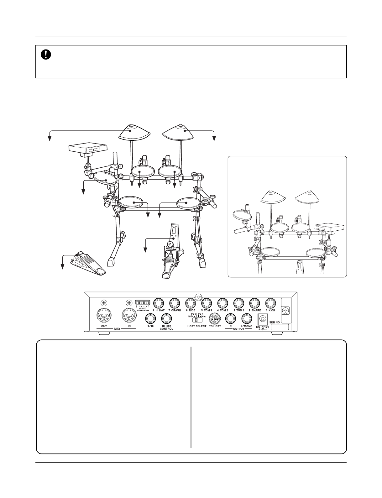
Setting Up
To prevent electric shock and damage to the devices, make sure the power is switched OFF on
the DTXPRESS and all related devices before making any connections to the DTXPRESS’ input
and output jacks.
■ Connecting the pads
Referring to the illustration shown below, connect the output cable from each pad to each Trigger Input Jack located on the rear panel of the
DTXPRESS.
The Trigger Input Jacks are all labeled (1 KICK, etc.) so make sure you connect each pad to its corresponding Trigger Input Jack.
to 6 RIDEto 7 CRASH
● For a move flexible snare/Hi-Hat
setup, set the pads as shown in
the illustration below.
to 3 TOM1 to 4 TOM2
to 8 HI HAT
Caution)
A cable equipped with a
stereo plug is required
when connecting the
Hi-Hat Controller.
to HI HAT
CONTROL
•Trigger Input Jacks are all stereo input type jacks.
Pads equipped with trigger switches like the TP80S, PCY80S, etc.
can be connected to these jacks.
• When a pad corresponding to the labeled input jack (1 KICK, etc.)
is connected, the DTXPRESS will automatically assign settings suitable for the pads. However, when pads and drum triggers that possess different characteristics are connected, it will be necessary to
assign suitable settings for parameters such as sensitivity, etc.
• Sensitivity is set in the Trigger Setup Edit mode’s [1-1. Pad Type]
(P. 36). By double clicking the [TRIG] button, you can hit the pad
you want to set and the DTXPRESS display will automatically jump
to the proper setting display.
•The input sensitivity switches (INPUT ATTENUATION) are sensitivity switches that correspond to Trigger Input Jacks 1 KICK-6 RIDE.
to 2 SNARE to 5 TOM3
to 1 KICK
H
L
The switch’s L position corresponds to a low sensitivity for pads
like TP, KP, PCY, BP, etc. The H position corresponds to a high
sensitivity proper for use with the DT10 Drum Trigger, etc.
• It is possible to connect the TP60, TP80S, PCY80S, etc. pads to the
1 KICK jack. You can also use the Hi-Hat Controller HH60, HH80,
HH80A as a kick pedal (Use [1-1. Pad Type] to assign settings.).
• In addition to the 1 KICK jack, the 9/10 jack can be used to connect
a second bass drum pedal to create a double-bass drum set.
• The 9/10 jacks correspond to a 2-trigger input that uses a stereo jack
for L (9) and R (10). We recommend the use of these jacks when
connecting the Yamaha Bar Pad (BP-80).
You can use an conversion cable plug (stereo plug m monaural plug
x2) to input two separate trigger signals.
10
Page 11
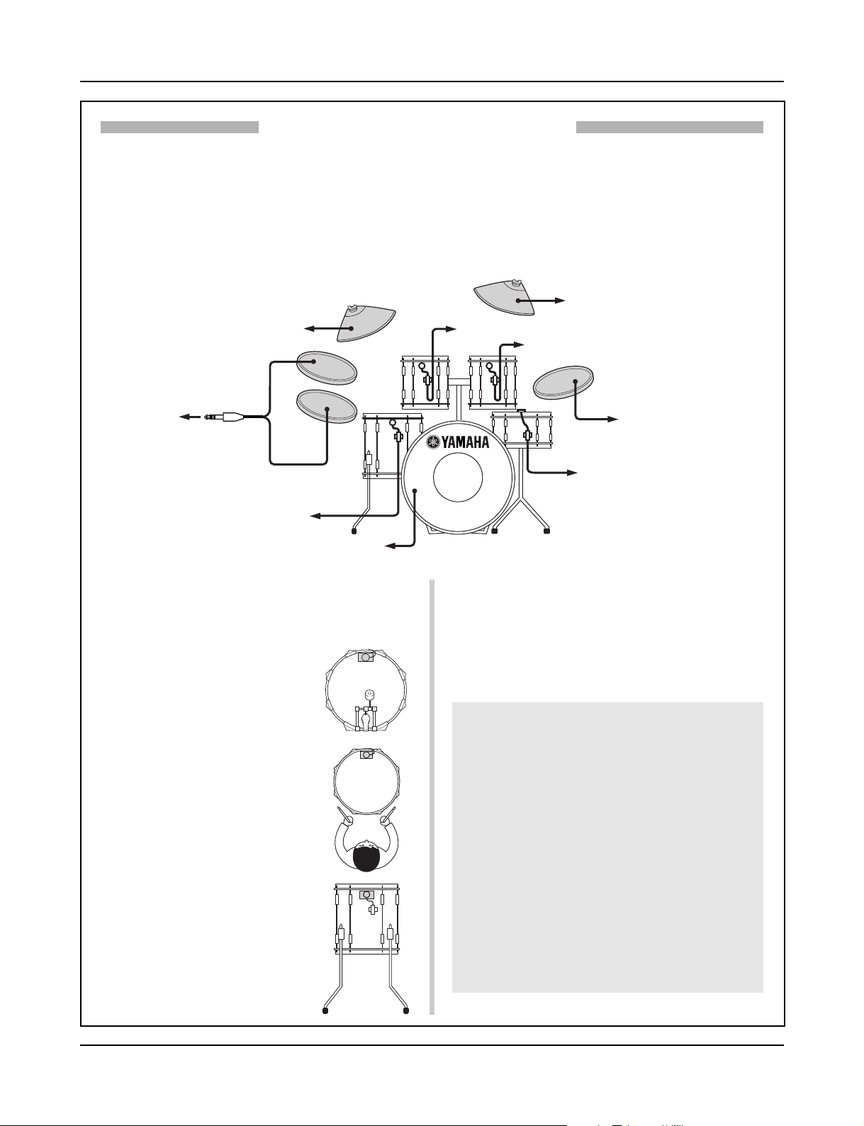
Setting Up
Setting up with Acoustic Drums
With the optional Yamaha DT10 Drum Triggers attached to a set of acoustic drums, it is possible to connect
acoustic drums to the DTXPRESS.
■ A setup example using both acoustic drums and drum pads.
Referring to the illustration shown below, connect the output cable from each pad and drum trigger to each Trigger Input Jack located on the rear
panel of the DTXPRESS.
* When using the drum triggers, appoint suitable settings in the Trigger Setup Edit mode’s [1-1. Pad Type]. (P. 36)
to 7 CRASH
to 6 RIDE
9
to 9/10
10
to 5 TOM3
to 1 KICK
■ Attach the Drum Trigger
Use the following procedure to attach the drum trigger sensors to your
acoustic drums.
• Attach to the Bass Drum
Mount the drum trigger sensor on the
batterhead of the bass drum close to the
edge of the rim.
* Make sure the sensor does not come in
contact with the rim.
• Attach to the Snare Drum
Mount the drum trigger sensor on the
batterhead of the snare drum close to the
edge of the rim across player.
* Make sure the sensor does not come in
contact with the rim.
• Attach to the Toms
Mount the drum trigger sensor on the shell
close to the edge of the rim.
* Make sure the sensor does not come in
contact with the rim.
*Place the trigger in a position where other
instruments (drum or percussion) will not
influence it.
to 4 TOM2
to 3 TOM1
to 8 HI HAT
to 2 SNARE
■ Removing the Drum Triggers
When changing the batterhead, carefully remove the drum trigger sensors with a knife, etc. before loosening the head.
* Be careful not to pull the cord when removing the trigger.
Taking Care of the Drum Triggers
• Make sure the surface of the batterhead or shell where
the trigger is to be mounted is free from dirt and grime.
Clean the surface with alcohol, etc. before attaching.
•To prevent broken trigger cords caused by the vibration
of the drum rim, secure the sensors and cords in place
with tape.
• Irregular vibration and sustained resonance on the
batterhead or shell may cause double-triggering. This
can be prevented by applying a mute to the batterhead
and controlling excessive vibration. We recommend the
use of the Yamaha Ring Mute.
• Once you have removed drum triggers and want to mount
them again, be sure completely remove the old tape and
apply new tape. Using used tape may cause problems
such as poor sensitivity, double-triggering, etc.
11
Page 12
Setting Up
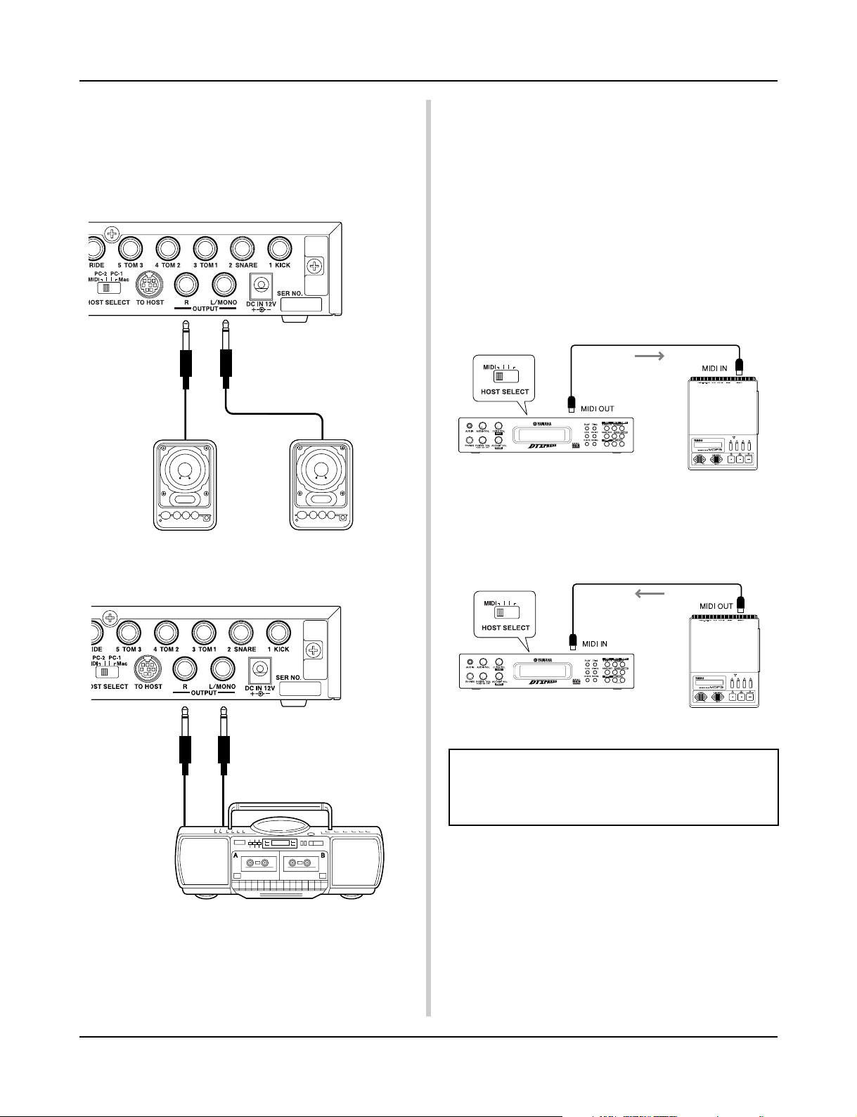
■ Connecting a Mixer or Audio Equipment
Connecting the OUTPUT L/MONO and R jacks on the rear of the
DTXPRESS to a mixer or audio equipment allows for audio reproduction through external speakers or the recording of your performance.
• Using speakers with built-in amplifiers.
•Recording your performance with the DTXPRESS to a
cassette tape deck.
■ Connecting a MIDI Device
Data in the DTXPRESS can be stored (Bulk Dump) to a Yamaha
MIDI Data Filer MDF3, etc. or other MIDI device.
Also, an external sequencer can be used to drive the DTXPRESS’
Tone Generator.
Furthermore, the use of MIDI functions allows for a wide range of
possibilities with the DTXPRESS.
Refer to the [Using MIDI] section (P. 25) on how to use MIDI
functions.
• Transmit MIDI Data
Use a MIDI cable to connect the MIDI OUT jack on the
DTXPRESS with the MIDI IN jack on the external MIDI device.
Set the HOST SELECT switch to the “MIDI’ position.
Set to “MIDI”
MIDI Data
DTXPRESS
MIDI Device
• Receive MIDI Data
Use a MIDI cable to connect the MIDI IN jack on the DTXPRESS
with the MIDI OUT jack on the external MIDI device.
Set the HOST SELECT switch to the “MIDI” position.
Set to “MIDI”
MIDI Data
* The OUTPUT jack is a standard monaural type phone jack. Please
use a cable equipped with a plug that matches device.
* When connecting to a monaural input device, please use the OUT-
PUT L/MONO jack on the DTXPRESS.
12
DTXPRESS
MIDI Device
Always use a standard MIDI cable when connecting devices. Also, use a MIDI cable that is not more than 15m in
length. Using a longer cable may result in irregular operation and other problems.
■ Connecting a Computer
The DTXPRESS is equipped with a built-in MIDI interface that
allows the DTXPRESS to be connected directly to a computer’s
serial board via the DTXPRESS’ TO HOST jack.
Sequencer software installed in the computer can be used to drive
the keyboard voices of the DTXPRESS and sequence data created
in the DTXPRESS can be edited in the computer.
Refer to the [Connecting a Computer] section (P. 26) for more
information.
Page 13
Setting Up
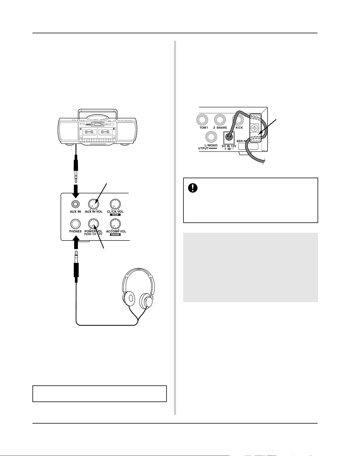
■ Connecting a CD Player, etc. (AUX IN jack)
The audio output from a CD player or cassette deck connected to
the AUX IN jack (stereo mini) on the front panel can be mixed
with the sound of the DTXPRESS and transmitted via the output
jacks on the rear panel.
This function is convenient when you want to play along with a
favorite song or enjoy performing with your friends.
The volume of the external signal is adjusted with the AUX IN
VOL knob.
Adjusts the volume of the AUX IN input jack.
■ Connecting the Power Supply
A special power source adaptor supplies power to the
DTXPRESS.
Make sure the power is switched OFF and connect the supplied
power adaptor to the DC IN jack on the rear panel.
To prevent the cord from becoming unplugged, wrap the cord
around the cord hook and secure.
cord hook
Please use the supplied power adaptor. The use of
any other power source may cause irregular operation or damage to the device.
Also, when the DTXPRESS is not to be used for a
long period of time, please unplug the power adaptor.
Adjusts the volume of the headphones.
■ Connecting a Pair of Headphones
(PHONES jack)
When you want to listen to the DTXPRESS with a pair of headphones, connect the headphones to the PHONES jack (stereo standard) on the front panel.
The headphone volume is adjusted with the POWER/VOL knob.
When using the headphones, do not damage your hearing. Adjust the volume to a comfortable level.
Before switching the power ON.
•To protect the speakers, headphones and the
DTXPRESS from damage, fully rotate the POWER/
VOL knob to the left (minimum volume) before
switching the power ON.
• Make sure the power is switched OFF on all external devices connected to the DTXPRESS. After the DTXPRESS’ power is switched ON, switch
the other device’s power ON.
13
Page 14
The DTXPRESS Quick Guide (Basic Functions List)
Play the DTXPRESS along
with your favorite CD or MD!
(Connect the line out from a
CD or MD player here.)
Connect a pair of headphones here to monitor the
DTXPRESS!
Press the knob to switch the power ON!
Rotate the knob to adjust the overall vol-
ume (transmitted to the OUTPUT jack).
Also controls the headphone volume.
Select the drum kit, song, and set the song
tempo and metronome.
m Enters the Drum Kit Play mode.
Control the volume of a CD
or MD player with this knob.
Controls the volume of the metronome’s
click voice!
Hold the [SHIFT] button and rotate this knob
to change the volume of the bass drum!
Controls the volume of the song accompaniment!
Hold the [SHIFT] button and rotate this knob to
change the volume of the snare drum!
Sets the pad’s sensitivity and dynamic
range.
m Enters the Trigger Setup Edit mode.
Set the basic settings and settings for MIDI
and the sequencer of the DTXPRESS.
m Enters the Utility mode
Starts/stops the metronome!
Hold the [SHIFT] button and press this
button to mute the song’s drum part.
Start/stop playback of the song!
Hold the [SHIFT] button and press this
button to start recording.
Save settings to the DTXPRESS’ memory.
Set a secondary function for the buttons and
knobs.
Change the instrument voice for each pad
in the drum kit or add reverb.
m Enters the Drum Kit Voice Edit
mode.
Edit the songs you create.
m Enters the Song Job mode.
Hold the [SHIFT] button and press this button to display the Tempo setting display!
Navigate through the setting display’s
pages.
Moves the cursor (flashing character).
Changes the value of the parameter
selected with the cursor.
Hold the [SHIFT] button and press this button to display the Groove Check display!
14
Page 15
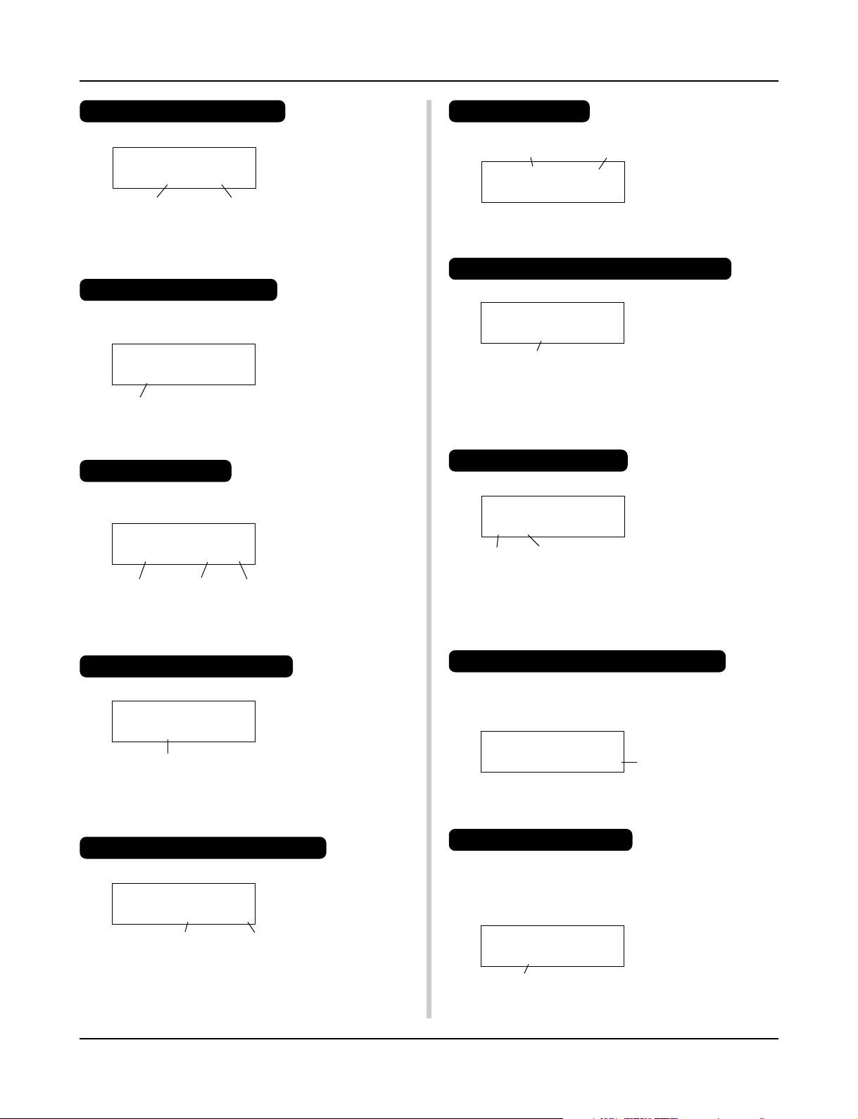
The DTXPRESS Quick Guide (Basic Functions List)
Listen to the Selected Song
1. Press the [PLAY] button to open this display,
KIT =1 Acoustic
SONG=1 Latiniq
Song Number Song Name
2. Use the [SEL<]/[SEL>] buttons to flash the song number.
3. Use the [VALUE–]/[VALUE+] buttons to select the song.
4. Press the [START/S] button to start playback!
Change the Song’s Tempo
1. Hold the [SHIFT] button and press the [PAGEt] button to
open this display,
TRIG =1 Medium
ƒ=110=--= 4/4=ƒ
Tempo
2. Use the [SEL<]/[SEL>] buttons to flash the tempo value.
3. Use the [VALUE–]/[VALUE+] buttons to set the tempo.
Set the Metronome
1. Hold the [SHIFT] button and press the [PAGEt] button to
open this display,
TRIG =1 Medium
ƒ=110=--= 4/4=ƒ
Tempo Beat Note
2. Use the [SEL<]/[SEL>] buttons to flash the parameter you
want to set.
3. Use the [VALUE–]/[VALUE+] buttons to set the value.
Change the Pad’s Sensitivity
1. Double-click the [TRIG] button to open this display,
TRIG IN= 1 ( 0%)
Gain=64 MVel= 32
Input Gain (Sensitivity)
2. Hit the pad that you want to edit (that pad will be selected).
3. Use the [SEL<]/[SEL>] and [VALUE–]/[VALUE+] buttons
to edit.
Select a Drum Kit
1. Press the [PLAY] button to open this display,
Drum Kit Number Drum Kit Name
KIT =1 Acoustic
SONG=1 Latiniq
2.
Use the [SEL<]/[SEL>] buttons to flash the drum kit number,
3. Use the [VALUE–]/[VALUE+] buttons to select a drum kit.
Change the Voice Volume For Each Pad
1. Double-click the [VOICE] button to open this display,
KIT IN=pad 1 V=Vol= 116 Pan= C
Volume Level
2. Hit the pad whose volume you want to change (that pad will
be selected),
3. Use the [SEL<]/[SEL>] and [VALUE–]/[VALUE+] buttons
to edit.
Change the Pad’s Voice
1. Press the [VOICE] button to open this display,
KIT IN=pad 1 V==K/017 BDaftty1
Voice Category
2. Hit the pad whose voice you want to change (that pad will be
selected),
3. Use the [SEL<]/[SEL>] and [VALUE–]/[VALUE+] buttons
to select the voice category and voice number.
Voice Number
Change the Reverb for the Drum Voice
1. After selecting the drum kit you want to add reverb to, press
the [VOICE] button, use the [PAGEs]/[PAGEt] buttons to
open this display.
KIT IN=pad 1
Reverb send= 15
2. Use the [SEL<]/[SEL>] and [VALUE–]/[VALUE+] buttons
to edit the reverb send level.
Reverb Send Level
Change the Output Sound Quality
1. Double-click the [UTIL] button to open this display,
UT TG MASTER
EQ Lo=+ 6 Hi=+ 0
Bass Treble
2. Use the [SEL<]/[SEL>] buttons to select either “Lo” (bass)
or “Hi” (treble),
3. Use the [SEL<]/[SEL>] and [VALUE–]/[VALUE+] buttons
to edit.
Save the Edited Settings
1. Press either the [VOICE] or [TRIG] button, use each mode’s
display to edit the settings.
2. Press the [SAVE/ENT] button,
3. Use the [VALUE–]/[VALUE+] buttons to set the save address.
Store Drumkit
To= 49 Init kit
Save Address
4. Press the [SAVE/ENT] button, after the confirmation display
appears, press the [SAVE/ENT] button again.
15
Page 16
Play the DTXPRESS!
Now that you have the DTXPRESS properly connected, let’s make some music!
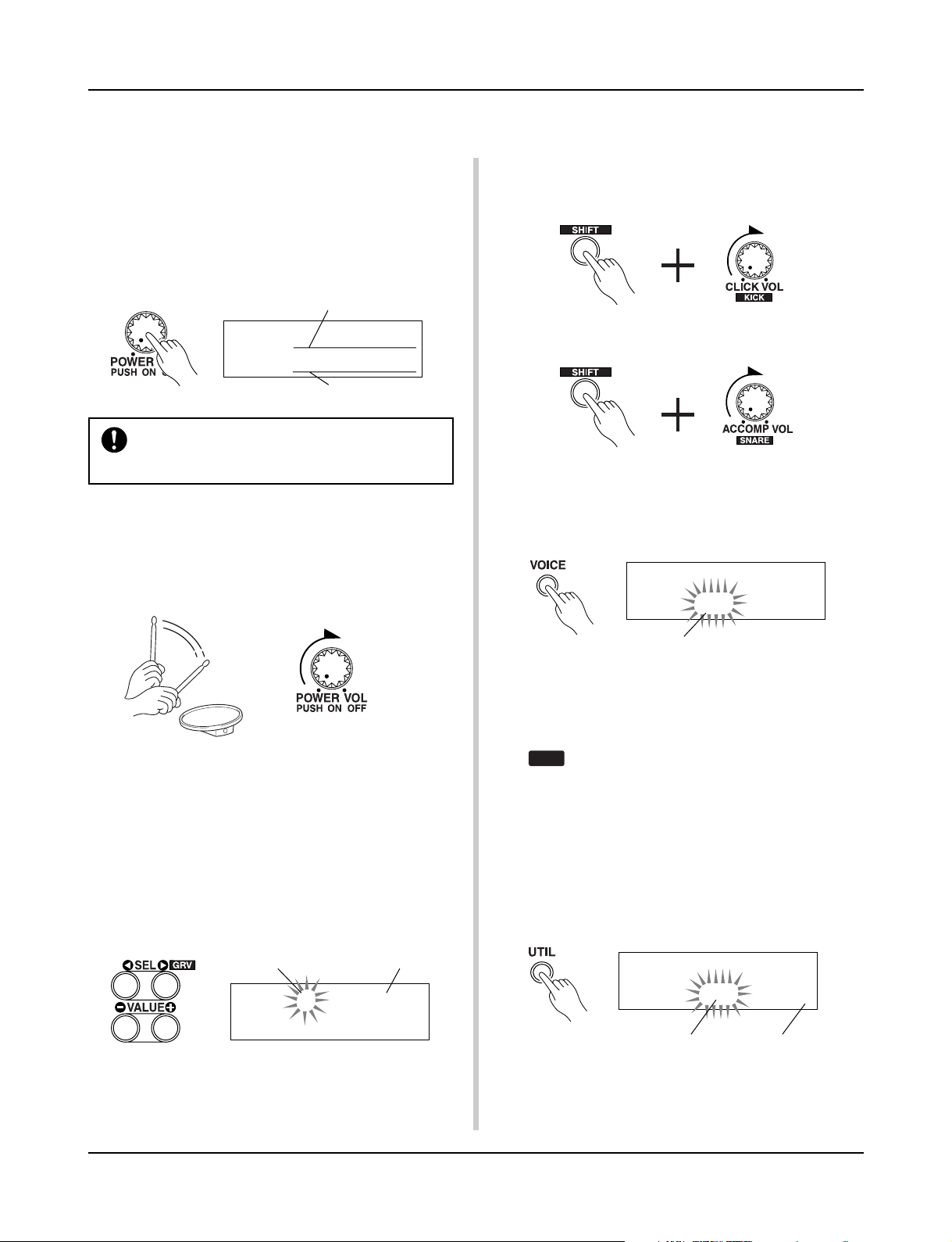
1. Switch the power ON
After confirming that each of the devices, pads, external devices, etc. are all properly connected, push the POWER/VOL
knob on the front panel to switch the power ON.
The DTXPRESS is ready to operate when the display, shown
below, for selecting the drum kit and song appears.
* The previously selected drum kit or song will be displayed.
Drum Kit
KIT =1 Acoustic
SONG=1 Latiniq
Song
To avoid damage to your speakers, first switch the
DTXPRESS’ power ON then switch on Audio Devices and the Mixer or Amplifier.
2. Hit a pad
While hitting a pad, rotate the POWER/VOL knob little by
little to the right until a comfortable volume level is reached.
The volume level is increased as the knob is rotated to the
right and decreased as it is rotated to the left.
4. Change the instrument volume for each pad.
• Hold the [SHIFT] button and rotate the Click VOL knob to
adjust the volume of the Bass Drum.
• Hold the [SHIFT] button and rotate the ACCOMP. VOL knob
to adjust the volume of the Snare Drum.
* The Bass Drum and Snare Drum volume settings, described
above, will reset when the power is switched off.
•Double-click the [VOICE] button, the volume setting display for each pad (Input Source) will be displayed.
KIT IN=pad 1 V=Vol= 116 Pan= C
3. Change the Drum Kit
Try out the voices for each of the kits.
Drum kit numbers 1-48 consist of 48 types of preset drum
kits that have been specially programmed by Yamaha. m [Pre-
set Drum Kit List] (P. 72)
Use the [SEL<]/[SEL>] buttons to move the flashing cursor to the drum kit number, then use the [VALUE–]/
[VALUE+] buttons to select the drum kit.
Drum Kit NameDrum Kit Number
KIT =1 Acoustic
SONG=1 Latiniq
Try out the different drum kits and select one drum kit you like.
*Some drum kits have Pad Songs and Drum Loop Voices
that will start when the corresponding pad is hit.
Volume
Hit the pad you want to adjust the volume of and use the
[VALUE–]/[VALUE+] buttons to adjust the volume.
* The same display can be used to adjust the pan (the posi-
tion of the voice within the stereo field) for each pad. (P. 41)
According to the setting in the Utility mode’s [1-3.
HINT
Volume Mode] (P. 52), the volume of the cymbal,
drums and other instruments can be adjusted using
the knobs shown above.
5. Change the sound quality heard through
the monitor.
Double-click the [UTIL] button, the sound quality setting display for the audio signal that is transmitted to the OUTPUT
jacks and PHONES jack will be displayed.
UT TG MASTER
EQ Lo=+ 6 Hi=+ 0
TrebleBass
Press the [SEL<]/[SEL>] buttons to move the flashing cursor to the Lo or Hi position, then use the [VALUE–]/[VALUE+]
buttons to adjust the sound quality.
16
Page 17
Play Along with the Metronome
Play the DTXPRESS along with the metronome.
Try out the Groove Check Function to check your rhythmic accuracy.
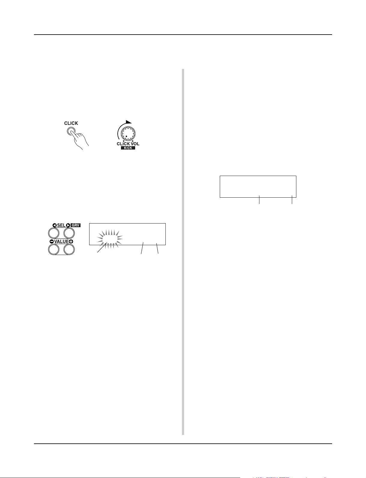
1. Turn On the Metronome
Press the [CLICK] button to start the metronome.
The lamp in the [CLICK] button will light every beat of each
measure.
Press the [CLICK] button again to stop the metronome.
The click voice volume is adjusted with the CLICK VOL knob.
1-1. Set Metronome Tempo
Hold the [SHIFT] button and press the [PAGEt] button, the
tempo setting display will appear.
Use the [SEL<]/[SEL>] buttons to move the flashing cursor
to the tempo value, then use the [VALUE–]/[VALUE+] buttons to set the desired tempo.
The Tempo setting range is q=30-300.
TRIG =1 Medium
ƒ=110=--= 4/4=ƒ
Tempo Value
1-2. Set the Metronome Beat
In the setting display shown above, press the [SEL>] button
to move the flashing cursor to the beat value, then use the
[VALUE–]/[VALUE+] buttons to set the desired beat.
The Beat setting range is 1/4-8/4, 1/8-16/8, 1/16-16/16.
1-3. Set the Metronome Note Value
In the setting display shown above press the [SEL>] button to
move the flashing cursor to the note value, then use the
[VALUE–]/[VALUE+] buttons to set the click tempo (finer
quantization).
1-4. Set the Click Voice and Other Settings
The metronome produces three different click voices.
“hi” will sound at the top of the measure, “mid” will sound
on every quarter note and “lo” will sound on the beats of
finer quantization.
Each of the click voices can be set to any voice (drum instrument voices) and pitch you like.
In the next section [Play with the Song] we will explain how
to change the voices in detail.
Refer to the Utility mode’s [3. Sequencer Group] (P. 56) section for more information.
Beat Note Value
2. Use the Groove Check Function
As you play the pads, the DTXPRESS’ Groove Check function will check your rhythmic accuracy and display the results.
Your timing is compared to the click of the metronome and
the accuracy is displayed.
2-1. Set the Metronome
Before you use the Groove Check Function, you will have to
select the tempo, beat and finer quantization that matches the
type of rhythm you want to practice.
2-2. Display the Groove Check Function
Hold the [SHIFT] button and press the [SEL>] button to display the Groove Check Function shown below.
KIT =1 Acoustic
Groov=+12Ave=+ 6
Average accuracyAccuracy of each stroke
2-3. Hit a Pad in Tempo with the Metronome
Press the [CLICK] button to start the metronome, then hit the
snare drum pad.
•The number that is displayed next to “Groov=” on the left
side of the display indicates the accuracy of each stroke on
the pad.
A “–” (minus) value is displayed when your timing is later
than that of the click voice (just timing) and a “+” (plus)
value is displayed when your timing is earlier than that of
the click voice.
•The number that is displayed next to “Ave=” on the right
side of the display indicates the overall accuracy or average of the values that are displayed next to “Groov=”. The
Groove Function can be used to check your accuracy on
the entire drum set or on an entire song.
The Groove Check Function can be used not only on the snare
drum, but on any of the DTXPRESS’ pads. Also, you can
change the metronome’s pattern to a sixteenth or triplet note
feel. Try practicing with some of the other settings.
* Hold the [SHIFT] button and press the [SEL>] button twice
to reset the data.
17
Page 18
Play Along with a Song
The DTXPRESS has a total of 95 preset songs that are good for rhythm practice.
Try and play along with a song.
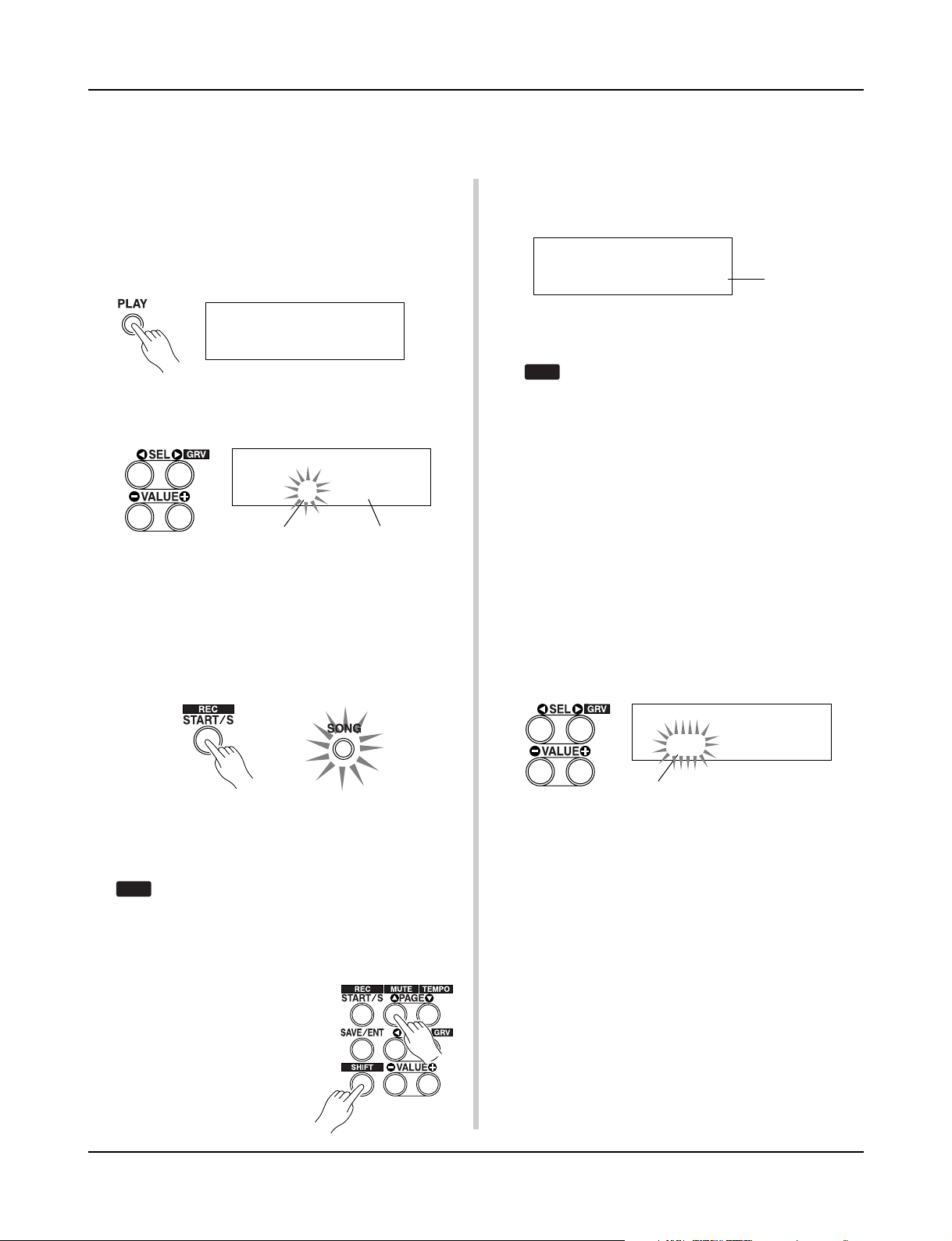
1. Select a Song
Select one of the DTXPRESS’ songs and listen to it. Song
numbers 1-95 are preset songs that have been created by
Yamaha.
m [Preset Song List] (P. 79)
Press the [PLAY] button to display the Drum Kit & Song display.
KIT =1 Acoustic
SONG=1 Latiniq
Use the [SEL<]/[SEL>] buttons to move the flashing cursor
to the song number, then use the [VALUE–]/[VALUE+] buttons to select the song.
KIT =1 Acoustic
SONG=1 Latiniq
Song Number Song Name
* When a song is switched, the drum kit also changes to a kit
that is set for that song.
2. Listen to the Song
When the [START/S] button is pressed, the song will start playback from the beginning.
The [SONG] lamp in the button will light on the first beat of
each measure.
While setting the Rhythm Mute, a “˚” will be displayed at the
end of the song name.
KIT =1 Acoustic
SONG=1 Latiniq˚
To cancel the Rhythm Mute, hold the [SHIFT] button and press
the [PAGEs] button again.
The mute function can be used during song playback.
HINT
To cancel the Mute, hold the [SHIFT] button and press the
[PAGEs] button again.
4. Adjust the Song Volume
The song volume is adjusted with the ACCOMP VOL knob.
Use both the ACCOMP VOL knob and the POWER/VOL knob
(overall volume of song and pads) to adjust the balance between the song and your drum part.
5. Change the Song’s Tempo
Hold the [SHIFT] button and press the [PAGEt] button to
display the Tempo Setting display.
In the same manner as the metronome, use the [SEL<]/
[SEL>] to move the flashing cursor to the Tempo value, then
use the [VALUE–]/[VALUE+] buttons to set the desired tempo
(q=30-300).
Indicates the
Rhythm Mute
The song will stop when it reaches the end.
You can stop the song during playback by pressing the [START/
S] button.
* Some songs repeat.
Before song playback, you can have the metronome
HINT
give a two-measure count. (m Utility Mode [3-5.
Count Switch] Reference Guide : P. 33)
3. Mute a Drum Part
Try playing along with the song.
Hold the [SHIFT] button and press the
[PAGEs] button, then press the
[START/S] button to playback the
song. A drum part in the song will be
muted (does not produce the part)
(Rhythm Mute Function).
You will play the drum part.
TRIG =1 Medium
ƒ=110=--= 4/4=ƒ
Tempo Value
Press the [PAGEs] button to return to the original display
(Drum Kit & Song setting display).
6. Play Along with the Click Voice
With the drum part muted, it may be a little difficult to keep
time. In this case, use the metronome along with the song.
Using the click voice as a reference will make it easier to play
along with the song.
Press the [CLICK] button to start the metronome. It will be in
tempo with the song. Press the [CLICK] button again to stop
the metronome.
The Click Voice’s volume can be adjusted using the CLICK
VOL knob.
18
Page 19
The metronome (click voice) can be set to start/stop
HINT
when the song starts/stops. (m [3-8. Click Mode]
(P. 58)
Play Along with a Song
Here, select “010 Marimba”.
Press the [CLICK] button to start the metronome and the
marimba voice will be delivered instead of the previously
assigned voice.
The same procedure can be used to change the other click
voices (“mid”, “lo”) to a voice you prefer.
Press the [PLAY] button to return to the original display
(Drum Kit & Song setting display).
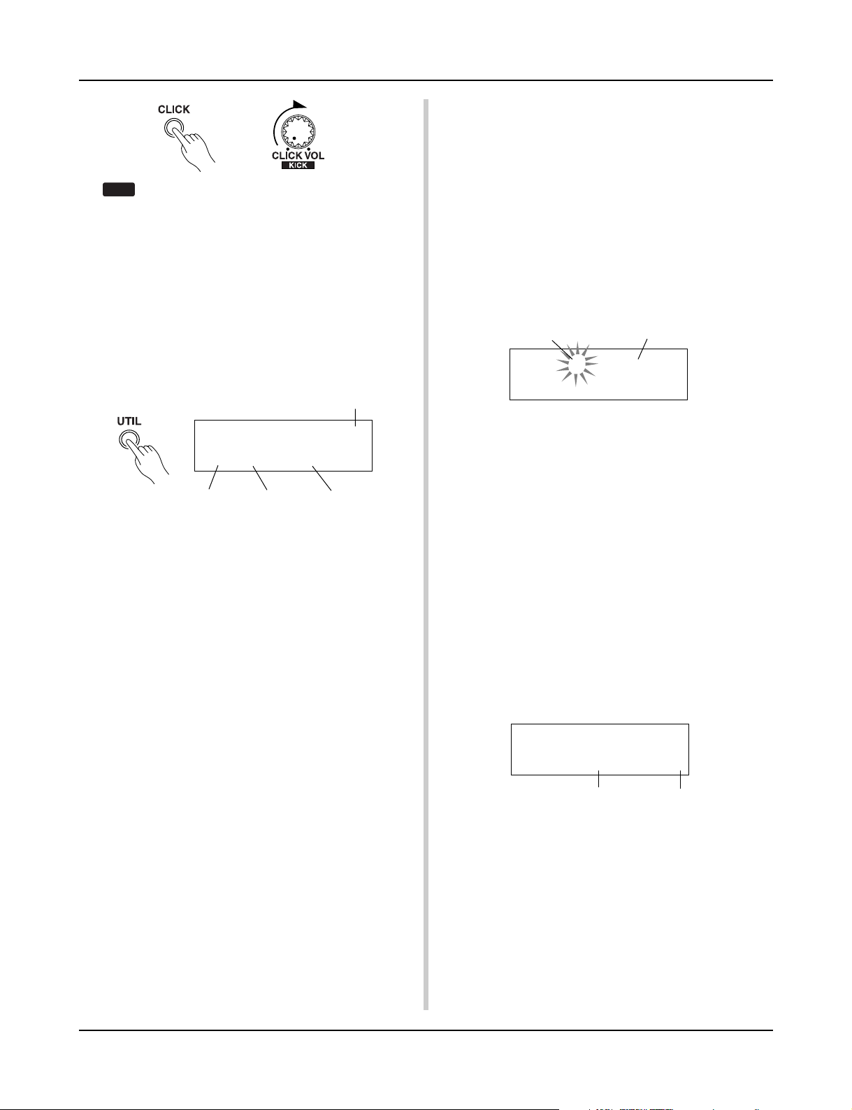
7. Change the Click Voice
When the click voice resembles voices that are found in the
song it might be hard to hear. In this case it is a good idea to
change the click voice.
•We will use the factory set 4-beat click voice (a high
and low bell voice) as an example here.
Change voice that is heard on the first beat.
Slowly press the [UTIL] button three times and the following
display will appear.
Click Voice Type
UT SEQ Click= hi
=P/053 MtBel
Voice Category Voice Number Voice Name
7-1. First, use the [SEL<]/[SEL>] buttons to move the flash-
ing cursor to the Click Voice Type position, then use the
[VALUE–]/[VALUE+] buttons to assign the “hi” click
voice (the click voice heard on the first beat).
7-2. Next, use the [SEL<]/[SEL>] buttons to move the flash-
ing cursor to the Voice Category position, then use the
[VALUE–]/[VALUE+] buttons to assign the Drum Voice
Category that will be used for the Click Voice.
Each of the following characters indicates a drum voice
category.
K: Acoustic Kick
k: Electric Kick
S: Acoustic Snare
s: Electric Snare
T: Acoustic Tom
t: Electric Tom
C: Cymbal
H: Hi-hat
P: Percussion
E: Effect 1
e: Effect 2
L: Drum Loop
m: misc. voices
Here, select the misc. voices “m”.
7-3. After selecting the category, press the [SEL>] button to
move the flashing cursor to the Voice Number, then use
the [VALUE–]/[VALUE+] buttons to assign the drum
voice that will be used for the click voice.
8. Change the Drum Kit
When you want to use a different drum kit with a particular
song, change only the drum kit number using the Drum Kit &
Song setting display.
Drum Kit Number
Drum Kit Name
KIT =1 Acoustic
SONG=1 Latiniq
9. Change the Song but Not the Drum Kit
Normally, when the song is switched the drum kit will be automatically switched to the kit that is set in the song. However,
if the Rhythm Mute Function ([SHIFT]+[PAGEs]) is used,
the drum kit will not change when the song is switched.
* Also, in the Utility mode’s [2-2. Channel 10 Program Change/
Receive Channel Event] (P. 54) set the Channel 10 Program Change to not receive program changes and then only
the song will change.
10. Mute Individual Drums
You can mute individual drums like the [Bass Drum], [Snare
Drum], [Cymbal], [Other Drum Instruments].
This function is convenient when you want to practice individual drum parts.
In the Drum Kit & Song setting display, press the [PAGEt]
button twice, the following display (Song & Mute) will appear.
SONG=1 Latiniq
Ki=®Sn=mCy=®Mi=®
Mute (Does not produce sound)
Use the [SEL<]/[SEL>] buttons to select the drum instrument (Ki: Bass Drum, Sn: Snare Drum, Cy: Cymbal, Mi: others) you want to mute, then press the [VALUE+] button to
change the speaker icon (®) to the mute icon (m).
To cancel the Mute Function, press the [VALUE–] button to
return to the speaker icon (®).
Produces sound
19
Page 20
Record Your Performance
Next, let’s try recording your performance to the DTXPRESS’ sequencer.
With song data you record you can switch drum kits, change the tempo and playback
in the same way as preset songs.
■ Recording System
• Recording can be done in any of the user songs (No. 96-127)
that supplied for recording. You cannot record to preset songs
(No. 1-95).
• User songs contain 2 tracks that can be recorded to. Recording can be done one track at a time.
• The song records (memory) data that precisely relates to when
and how each pad was hit, and stores that information. This
is called sequence data. MIDI data from the MIDI IN/TO
HOST jacks can be recorded simultaneously.
•Sequence data can be freely used to change the tempo, select
the voice or drum kit during playback.
m P. 48 [2. Program Change, Bank Select]
• Before recording, set the number of measures for the song
you want to record. Recording is done in real-time. When
the end of the assigned measure is reached, the record function can be set to act in one of two ways. (1) The song will
automatically stop (Replace) and recording will be complete.
(2) The song will repeat from its beginning and further data
can be added to the previously recorded data (Overwrite).
OK, Let’s Start Recording
1. Select the Song You Want To Record
Press the [PLAY] button to display the Drum Kit & Song display, select a User Song number (No. 96-127).
* User songs that already contain data in both tracks cannot
be recorded to.
* If a song is not selected when you start to record, the lowest
numbered empty user song will automatically be selected to
record. In the same manner, an empty user song will be selected if a preset song has been selected for recording.
* When there is data in the other track, the number of mea-
sures in that track will determine the length of the song.
2-2. Select the Record Mode
Select the method for recording from the following record
modes.
Overwrite (Ovr): The record operation will be in a repeat
mode. When the song reaches the end of the last measure, it will automatically start again from the beginning
and new data will be added to the track’s previous data.
Replace (Rpl): When the song reaches the end of the as-
signed measure or the [START/S] button is pressed, recording will stop (will not repeat).
2-3. Set the Track For Recording
Select either track 1 or 2 for recording.
2-4. Set the Metronome’s Tempo and Beat
Set the tempo and beat that will be used by the Metronome
when recording.
2-5. Set the Quantize Function
The Quantize function is used to align the timing of your performance with that of the nearest specified beat. The accuracy
of quantization is assigned with a note value. The quantize
function can be used when recording.
* If this function is set to “no”, the quantize function will not
operate.
*You can use the Quantize function after recording is com-
plete. (P. 49)
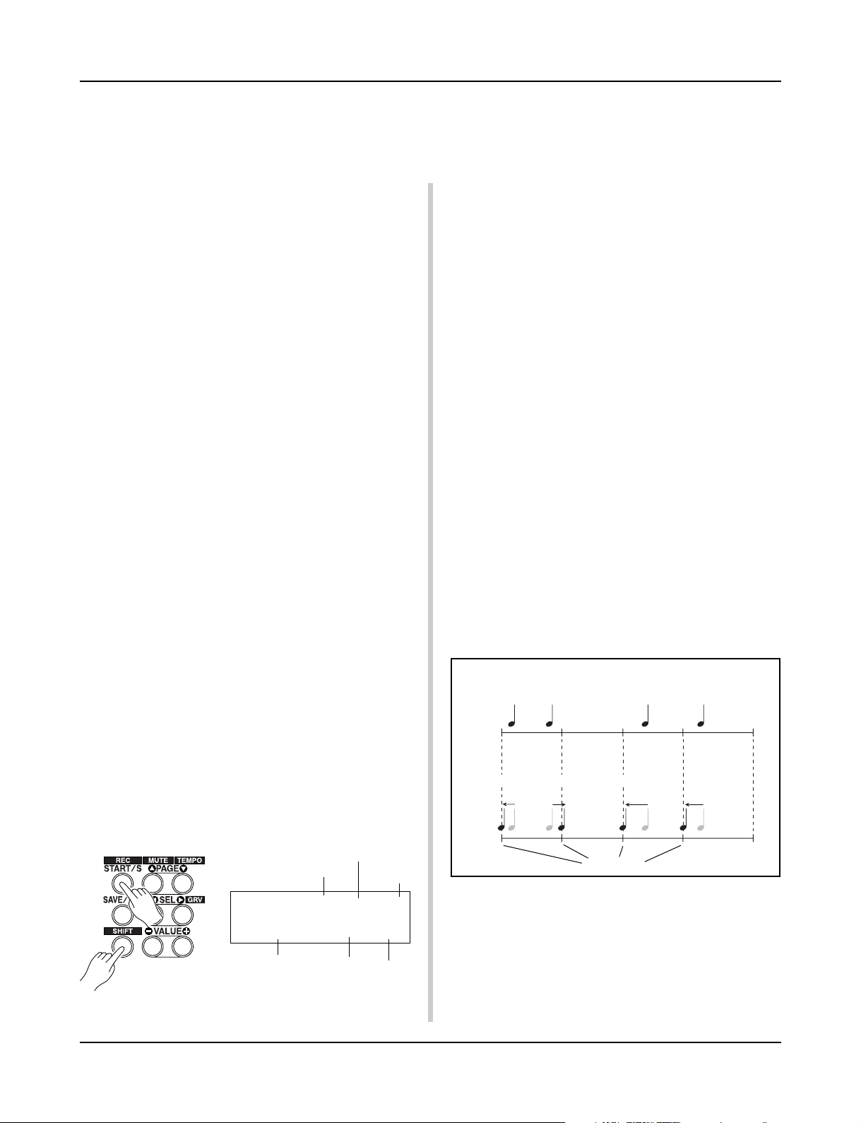
● How Quantize Works (an example)
• Recorded notes were not played in time.
2. Set the Recording Conditions
Hold the [SHIFT] button and press the [START/S] button, the
following Recording Conditions setting display will appear.
Use the [SEL<]/[SEL>] buttons to select the parameter you
want to set, then use the [VALUE–]/[VALUE+] buttons to set
each of the following recording conditions.
2-1. Set the Number of Measures to be Recorded.
Record Mode
Number of Measures for
Recording
REC M= 32=Rp1†=1
ƒ=120 B= 4/4Q=©
Tempo
Determine the number of measures you want to record and set.
20
Beat
Track
Quantize
• The Quantize Function aligns the timing.
Just Timing
3. Start Recording
Press the [START/S] button, after a two-measure count recording will start. Record while listening to the metronome’s click
voice.
* When the track assigned for recording contains data and
the [START/S] button is pressed, the error message “Data
not Empty” will appear and the recording operation will
not be carried out.
Page 21
Record Your Performance
● When the Record Mode is set to Replace (“Rpl”).
The following display will appear while recording (only displayed, cannot be changed).
The measure number currently being recorded.
REC M= 18=Rp1†=1
Now Recording.
When the end of the assigned measure number is reached, recording will automatically stop, and the display will return to
the Drum Kit & Song display.
*You can also stop recording by pressing the [START/S] but-
ton.
● When the Record Mode is set to Overwrite (“Ovr”).
The following display will appear while recording (only displayed, cannot be changed).
The measure number currently being recorded.
REC M= 18=Ovr†=1
UNDO press ENT
The song being recorded will continuously repeat until the
[START/S] button is pressed.
When the song reaches the end of the last measure, it will
automatically start again from the beginning and new data will
be added to the track’s previous data.
When the record mode is set to Overwrite (“Ovr”), press the
[SAVE/ENT] button while recording to “undo” (do again) the
record operation. The data previously recorded from the beginning of the song, up until the [SAVE/ENT] button was
pressed, will revert to the data originally present.
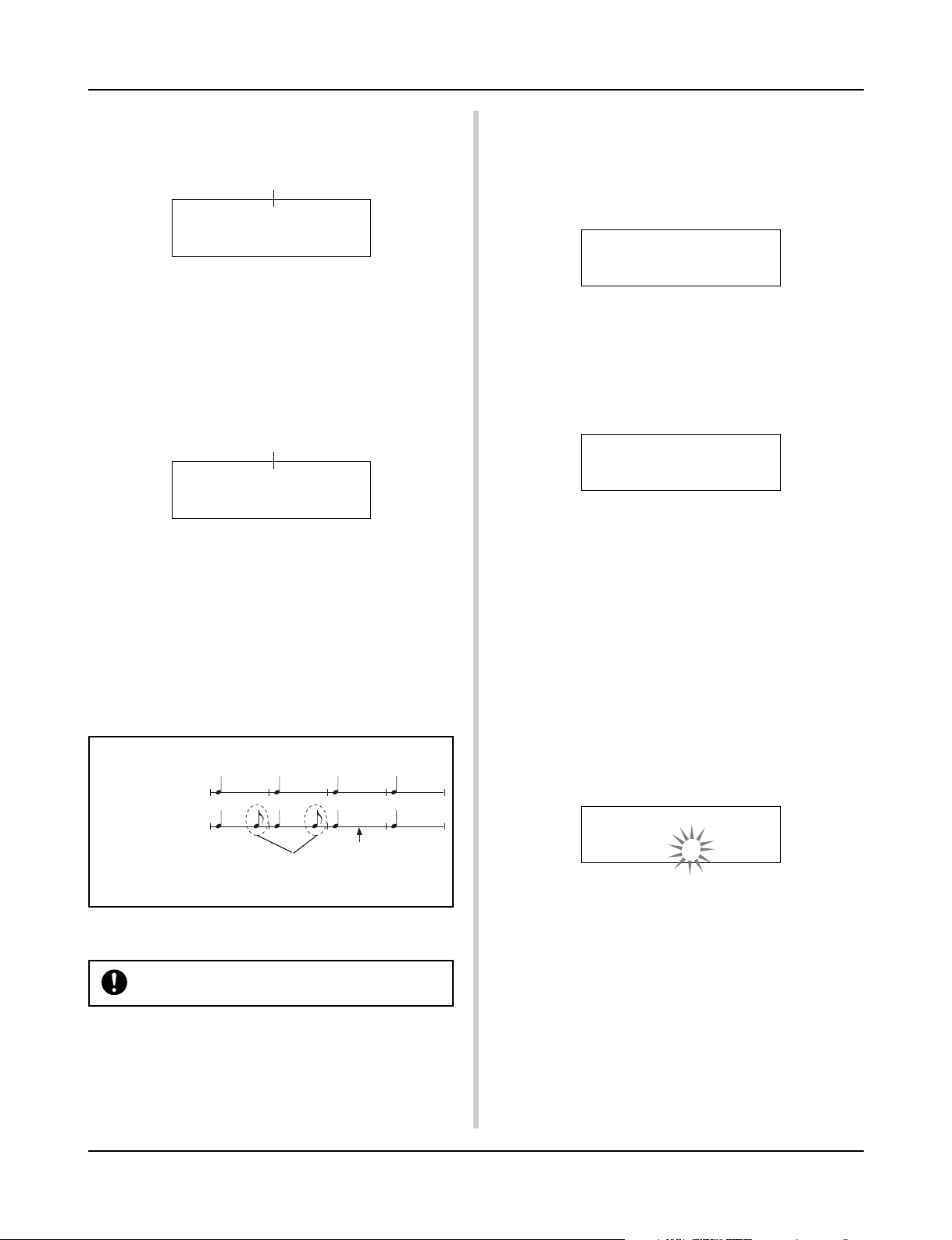
● How the “Undo” Works (an example)
Data recorded
the first time.
Data recorded
the second time.
Pressing the [SAVE/ENT] button here,
only the data recorded the second
time will be erased.
Press the [START/S] button to stop recording, the display will
return to the Drum Kit & Song display.
If the power is cut off during recording, all user song
data may be lost. Please use caution.
4. Listen to the Song
Press the [START/S] button, playback of the song you just
recorded will start from its beginning. You can also change the
drum kit and playback the song with a different kit.
m P. 48 [2. Program Change, Bank Select]
5. Redo the Recording
To record again, use the following procedure to clear previously recorded data in the track, then try recording again.
• To clear song data (both tracks 1 and 2).
Double-click the [SONG] button, the Clear Song display,
shown below, will appear.
SONG Clear Song
Are you sure ?
Press the [SAVE/ENT] button, all of the data in the currently
selected song will be cleared.
• To clear data from one track.
Double-click the [SONG] button, after the Clear Song display,
shown above, appears press the [PAGEs] button 2 times. The
Clear Track display shown below will appear.
SONG Clear Track
Track=1
Use the [VALUE–]/[VALUE+] buttons to set the number of
the track you want to clear, then press the [SAVE/ENT] button, “Are you sure ?” will appear in the display. Press
the [SAVE/ENT] button again, all of the data in the currently
assigned track of the selected song will be cleared.
6. Record One More Track
In the same manner, one more track can be used to record.
However, the number of measures cannot be changed.
7. Give the Song a Name
On the display, “no name” will appear for the song name.
Change the name to an original name.
Press the [SONG] button to display the song mode, use the
[PAGEs]/[PAGEt] buttons to select the Song Name setting
display shown below.
SONG
SngName=no name
Use the [SEL<]/[SEL>] buttons to move the flashing cursor
to the character you want to change, then use the [VALUE–]/
[VALUE+] buttons to select the desired character.
The available characters to choose from are listed below.
(in order)
Space
!"#$%&'()*+,-.0123456789:;<=>?@
ABCDEFGHIJKLMNOPQRSTUVWXYZ[\]^_`
abcdefghijklmnopqrstuvwxyz{|}ßå
A maximum of 8 characters can be used for the song name.
If the power is switched off, the completed
song will be stored.
21
Page 22
Create Your Own Original Drum Kit
You can assign voices you like to each of the pads, and set the tuning (pitch), voice,
decay, reverb, etc. to create your own original drum kit.
1. Select the Drum Voice
First, select a drum voice for the kit you want to create. Let’s
try assigning a snare drum voice.
It doesn’t matter what drum kit you select (the drum kit that is
created will be saved to a user drum kit (No. 49-80)).
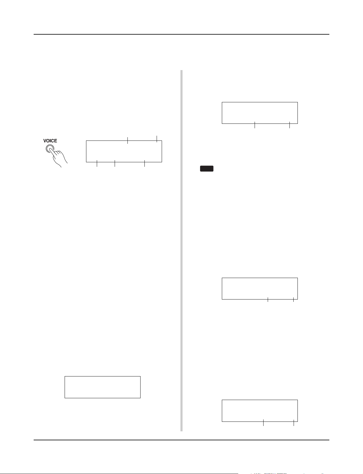
1-1. Select a Snare Drum for the Input Source.
Press the [VOICE] button and the display for selecting the
Drum Voice will appear.
Input Source Layer Number
KIT IN=pad 1 V=1
=K/017 BDaftty1
Voice Category Voice Number Voice Name
Use the [SEL<]/[SEL>] buttons to move the flashing cursor
to the input source position, then use the [VALUE–]/[VALUE+]
buttons to select “pad 2”. This means that the snare pad input that is connected to trigger input jack 2 SNARE is selected.
The value “V=1” indicates that the layer number=1. Two voices
can be delivered (2 layer) with one input source (trigger input). In this case, you will have to assign which voice will be
used here.
1-2. Select the Drum Voice Category.
Next, decide the drum voice category.
The drum voice category is the same category that was used in
the Metronome Click Voice (P. 19).
For this example, let’s select “s: Electric Snare”.
Use the [SEL<]/[SEL>] buttons to move the flashing cursor
to the voice category position, then use the [VALUE–]/
[VALUE+] buttons to select “s”.
A “*” mark will appear between “KIT” and “IN”. This is to
let you know that data in the currently selected drum kit has
changed.
1-3. Select the Drum Voice.
Next, let’s select a drum voice.
Using the same procedure you used when you changed the
metronome click voice (P. 19), press the [SEL>] button to
move the flashing cursor to the Voice Number position, then
use the [VALUE–]/[VALUE+] buttons to assign the drum
voice. For this example, let’s select “014 Dance01”.
KIT IN=pad 2 V=1
=s/014 Dance01
2. Try Changing the Volume
Let’s change the volume of the drum voice that is delivered when
the pad is hit. Adjust the volume balance between the other pads.
Press the [PAGEt] button and the following display will ap-
pear.
KIT*IN=pad 2 V=Vol= 120 Pan= C
Volume Pan
Use the [SEL<]/[SEL>] buttons to move the flashing cursor
to the volume level position, then use the [VALUE–]/
[VALUE+] buttons to set the volume level.
*“V=-“ appears when the drum voice is not a 2 layer voice.
Press the [VOICE] button to monitor the voice just as
HINT
if the pad were hit.
3. Try Changing the Pan
Using the same display, you can change the pan setting for the
drum voice.
According to this setting you can move the position of the
currently selected drum voice within the stereo field as follows: “L64” (left side) – “C” (Center) – “R63” (right side).
Press the [SEL>] button to move the flashing cursor to the
pan level position, then use the [VALUE–]/[VALUE+] buttons to set the pan value.
4. Try Changing the Tuning (Pitch)
Let’s try and change the tuning (pitch) of the drum voice.
Press the [PAGEt] button and the following display will appear.
KIT*IN=pad 2 V=Tune C= 0 F= 0
Tuning in half-step increments
Use the [SEL<]/[SEL>] buttons to move the flashing cursor
to the “C” or “F” position, then use the [VALUE–]/[VALUE+]
buttons to set the pitch of the voice.
Tuning for “C=” is in increments of a half-step, tuning for
“F=” is in steps of approximately 1.17 cents.
5. Tr y Changing the Decay (the length of time
it takes for the voice to fade)
Let’s try and change the voice’s decay (the length of time it
takes for the voice to fade).
Press the [PAGEt] button twice and the following display
will appear.
Finer tuning
With this, we have assigned a drum voice for the kit
you want to create.
Now, let’s try to edit this drum voice in several ways
and create your own original snare drum voice.
22
KIT*IN=pad 2 V=Decay=+ 8 Fc= 0
Decay
Filter Cutoff Frequency
Page 23
Create Your Own Original Drum Kit
HINT
Use the [SEL<]/[SEL>] buttons to move the flashing cursor
to the decay value position, then use the [VALUE–]/[VALUE+]
buttons to set the amount of decay.
A + (plus) value will produce a faster decay.
6. Tr y Changing the Character of the Voice
(Filter Setting).
Using the same display you can set the Filter Cutoff Frequency.
Try to change the character of the voice (the brightness of the
voice).
Press the [SEL>] button to move the flashing cursor to the
“Fc=” position, then use the [VALUE–]/[VALUE+] buttons
to set the value.
A + (plus) value will produce a brighter sound.
7. Tr y Adjusting the Volume Balance of the 2
Layer Voice.
If the selected drum voice is made with 2 layers (1 drum voice
made with 2 voice waves), the volume balance can be adjusted
between the 2 waves.
Press the [PAGEs] button and the following display will appear.
KIT*IN=pad 2 V=1
LayerBalance=+20
Use the [SEL<]/[SEL>] and [VALUE–]/[VALUE+] buttons
to select the layer number.
* If the assigned voice is not made of 2 layers this setting is
not valid.
Press the [SEL>] button to move the flashing cursor to the
layer balance position, then use the [VALUE–]/[VALUE+]
buttons to set the layer balance value.
Layer Number
Layer Balance
8. Adjust the Amount of Reverb.
Let’s try and adjust the amount of reverb effect that is applied
to the voice.
Use the [PAGEs]/[PAGEt] buttons to select the display
shown below.
KIT*IN=pad 2
Reverb send= 40
Reverb send level
10. Save the Voice You Have Created
Let’s save the drum voice you created to the DTXPRESS’
memory. Drum kit numbers “49” – “80” (these are called user
drum kits) are used for saving individual drum kits.
Press the [SAVE/ENT] button, the following display will appear.
Store Drumkit
To= 49 Init Kit
Use the [VALUE–]/[VALUE+] buttons to set the drum kit number (“49” – “80”) for saving your drum kit to.
Press the [SAVE/ENT] button, “Are you sure ?” will
appear on the display asking for confirmation.
*To cancel the save operation, press the [VALUE–] button.
Press the [SAVE/ENT] button again, the save operation will
be carried out, then “Complete!” will appear. After “Com-
plete!” appears, the display will return to the Drum Kit &
Song setting display.
11. Give Your Drum Kit a Name
The completed drum kit will still have the original drum kit’s
name.
Press the [VOICE] button to enter the Drum Kit Voice Edit
mode, then press the [PAGEt] button to display the Drum
Kit Name setting display shown below. With the same procedure you used when you made a Song, give your drum kit an
original name. (P. 21)
KIT Common
KitName=Acoustic
Now the drum kit with the original snare drum
you created is complete.
Use the same procedure to create drum voices
for the other pads (input source) and create a
complete drum kit that is all your own.
Use the [SEL<]/[SEL>] buttons to move the flashing cursor
to the reverb send level position, then use the [VALUE–]/
[VALUE+] buttons to set the value.
Large values will increase the amount of reverb applied to the
voice, “0” will produce no reverb.
* This setting is the reverb level for each input source. The
overall reverb level for the drum kit is set in [5-2. Drum Reverb Send] (P. 47)
9. Adjust the Balance Between Layer 1 and 2.
If you have used a 2 layer voice in the voice you just created,
adjust the balance between the voices by adjusting the volume
of each voice.
*You can select the conversion curve for 2 voices.
m Drum Kit Edit Mode [2-1. Cross Fade] (P. 43)
The DTXPRESS also has keyboard voices that comply with
the GM System Level 1. So, not only drum voices, but piano, guitar, bass, strings, brass, reeds, effect, etc. can be
delivered when the pad is struck.
To use keyboard voices with the pads first, change the pad’s
MIDI channel to any channel other than “10” (P. 42 [1-7.
Channel, Gate Time]), then select the MIDI note number
of the voice you want to use in (P. 42 [1-6. Note Number] )
* If the [2-5. Key Off Enable] (P. 44) is set to “disable”,
some voices may sound continuously. In this case, press
the [SHIFT] + [VOICE] buttons to stop voices sounding.
23
Page 24
Getting More Out of Your DTXPRESS
There is much more to the DTXPRESS than what we have covered so far.
With a full understanding of these functions you can get the most out of the DTXPRESS.
■ Factory Set
The internal settings of the DTXPRESS will be returned to their
factory preset condition.
m Utility Mode [1-6. Factory Set] (P. 53)
If the factory set operation is carried out, data for
the User Drum Kit, User Trigger Setups and User
Songs will be lost.
■ Functions related to connections and input
source (pads)
•Drum kits can be selected by hitting a pad. For example, with
an optional Yamaha Bar Pad BP80 connected to the trigger
input jack 9/10, you can hit the left bar pad to decrease the
value of the drum kit number by 1. Likewise, hitting the right
bar will increase the value of the drum kit number by 1.
When the function described above is used in any drum kit
m P. 38 [2-1. Increment/Decrement]
When the function described above is used in a specified drum
kit.
m P. 44 [2-6. Function]
•A hi-hat controller connected to the trigger input jack 1 KICK
can be used as a KICK pedal.
m P. 36 [1-1. Pad Type]
•Several methods are available for adjusting the sensitivity of
pads and drum triggers.
To automatically set suitable settings for pads and drum triggers
connected to the DTXPRESS
m P. 36 [1-1. Pad Type]
To greatly modify the sensitivity,
m Change the INPUT ATTENUATION switch on the rear panel. (P.
10)
For minor adjustments to the sensitivity,
m P. 36 [1-2. Gain, Minimum Velocity]
• Set the sensitivity of the hi-hat controller connected to the HI
HAT CONTROL jack.
m P. 47 [5-3. Hi-Hat Sensitivity]
• Set the point at which the hi-hat controller “closes” the hi-hat
and the amount of time it takes to detect a foot splash
m P. 53 [1-5. Hi-Hat Offset]
• Eliminate cross-talk (mixed input signals between the jacks)
m P. 37 [1-4. Self Rejection/Rejection]
m P. 37 [1-5. Specified Rejection]
•Eliminate double-triggers (2 sounds played at the same time)
m P. 37 [1-4. Self Rejection/Rejection]
• Set the velocity curve that determines the relationship between
the strength that the pad is hit and the volume that is produced
m P. 37 [1-3. Velocity Curve]
• Switch the signals between trigger input jacks 1 and 9/10
m P. 38 [2-2. Input Exchange]
• Copy trigger setup data from one trigger input jack’s setup to
another
m P. 37 [1-6. Trigger Setup Copy]
•Temporarily prohibit reception of trigger signals from all pads
connected to the DTXPRESS
m P. 52 [1-2. Trigger Bypass]
Switch the trigger bypass function (above) ON/OFF from a
pad.
m P. 44 [2-6. Function]
■ Set the Reverb
The DTXPRESS is equipped with a digital reverb section.
• Set the reverb type and reverb time for each drum kit
m P. 45 [3-1. Reverb Type, Time]
•The following three methods can be used to set the amount of
reverb.
Adjust the reverb level for the voice delivered by the pad of each
input source,
m P. 43 [2-2 Reverb Send]
Adjust the reverb send level for the entire drum kit,
m P. 47 [5-2. Drum Reverb Send]
Adjust the DTXPRESS’ overall reverb send level,
m P. 45 [3-2. Reverb Master Return]
Adjust the amount of reverb for each drum kit in the user drum
map
m P. 60 [5-6. Reverb Send]
• Bypass the reverb circuit (no reverb).
m P. 59 [4-4. Reverb Bypass]
■ Settings related to the Drum Voice
• Set the cross fade between voice layers 1 and 2.
m P. 43 [2-1. Cross Fade]
• Set the rim voice to simultaneously trigger the pad voice when
stereo pads are used.
m P. 45 [2-8. Rim to Pad]
• Set the alternate group and key assign mode for voices that are
delivered simultaneously.
m P. 43 [2-3. Alternate Group, Key Assign Mode]
• Set the key ON/OFF that is transmitted when the pad is hit.
m P. 44 [2-4. Hold Mode]
• Set whether to recognize or not key off messages.
m P. 44 [2-5. Key Off Enable]
24
Page 25
Getting More Out of Your DTXPRESS
• Set the volume of the entire drum kit.
m P. 47 [5-1. Volume]
• Create an original drum kit.
m P. 59 [5. MAP (Drum Map Group)]
■ Settings Related to the Tone Generator
•The following settings will have an effect over the entire tone
generator.
Equalizer (adjust the tone quality), Tuning, Volume, Reverb Bypass
m P. 58 [4. TG (Tone Generator) Group]
■ Settings Related to the Song
• Automatically switch the main song when the drum kit is
switched.
m P. 47 [5-4. Song Select]
• Control the simultaneous playback (start/stop) of up to 3 songs
by hitting the pad.
m P. 44 [2-7. Pad Song]
• Edit the following parameters in song sequencer data
Tempo, Repeat Playback, Program Change, Bank Select, Volume, Pan, Song Copy, Quantize, Clear Track, Merge Track,
Clear Song and Song Name
m P. 48 [Song Job Mode]
• Playback the song at the set tempo, even when the song is
switched.
m P. 58 [3-7. Use Tempo]
■ Other Functions
• Along with triggering voices the pads can be used for a variety
of control functions.
Pad song playback/stop, metronome’s click voice ON/OFF, switch
drum kits, trigger bypass ON/OFF and playback/stop of the main song.
m P. 44 [2-6. Function]
• Assign pads (trigger input source) in the Trigger Setup Edit
mode and Drum Kit Voice Edit mode simply by hitting the
pad.
m P. 52 [1-1. Learn Mode]
• Adjust the volume of the cymbal, drum and other instruments
using the ACCOMP. VOL. knob and CLICK VOL. knob.
m P. 52 [1-3. Volume Mode]
•Display the page that was previously used in the Trigger Setup
Edit mode and Drum Kit Voice Edit mode.
m P. 52 [1-4. Jump to Recent Page]
■ Using MIDI
The DTXPRESS is equipped with MIDI IN/OUT jacks and a TO
HOST jack. These jacks are used to exchange data between an
external MIDI device/computer and the DTXPRESS. The MIDI
data format is used.
About MIDI
MIDI (Musical Instrument Digital Interface) is a world standard that provides a means to connect instruments and computers and allow them to transmit and receive performance
and other data. This standard allows computers and instruments of different makers and types to communicate.
Using MIDI the DTXPRESS can perform the following operations. Refer to the [Connecting a MIDI Device] section (P. 12) for
more information on connecting external MIDI devices.
● Bulk Dump/Bulk In
Data for each of the settings in the DTXPRESS can be transmitted
to an external MIDI device or computer (Bulk Dump). When connected to the DTXPRESS, a device equipped with a “save” function, such as the Yamaha MDF3, etc., can be used to backup your
data and create a library with.
Also, the data saved in an external device can be transmitted back
to the DTXPRESS (Bulk In).
● Synchronized Playback with External MIDI
Devices
When two MIDI devices that use tempo information such as a
sequencer, etc. are connected, one device must play along with the
other (sync) using tempo information (clock) transmitted by the
master device.
Playback of an external sequencer’s data can be synchronized with
the DTXPRESS’ song and metronome click. Also, playback of
the DTXPRESS’ song can be synchronized to an external sequencer.
● Transmit and Receive MIDI Data
•The DTXPRESS’ tone generator can be driven by MIDI song
data (sequence data) transmitted from an external MIDI device. This song data can be recorded along with your performance on the DTXPRESS.
• The DTXPRESS’ drum kits can be switched and song playback can be controlled from an external MIDI device.
• Hi-hat controller information can be transmitted via MIDI.
A variety of other MIDI information can also be transmitted and
received.
Refer to the [Drum Kit Voice Edit Mode] (P. 39), [Utility Mode]
(P. 51), [MIDI Data Format], (P. 80) etc. for more information.
25
Page 26
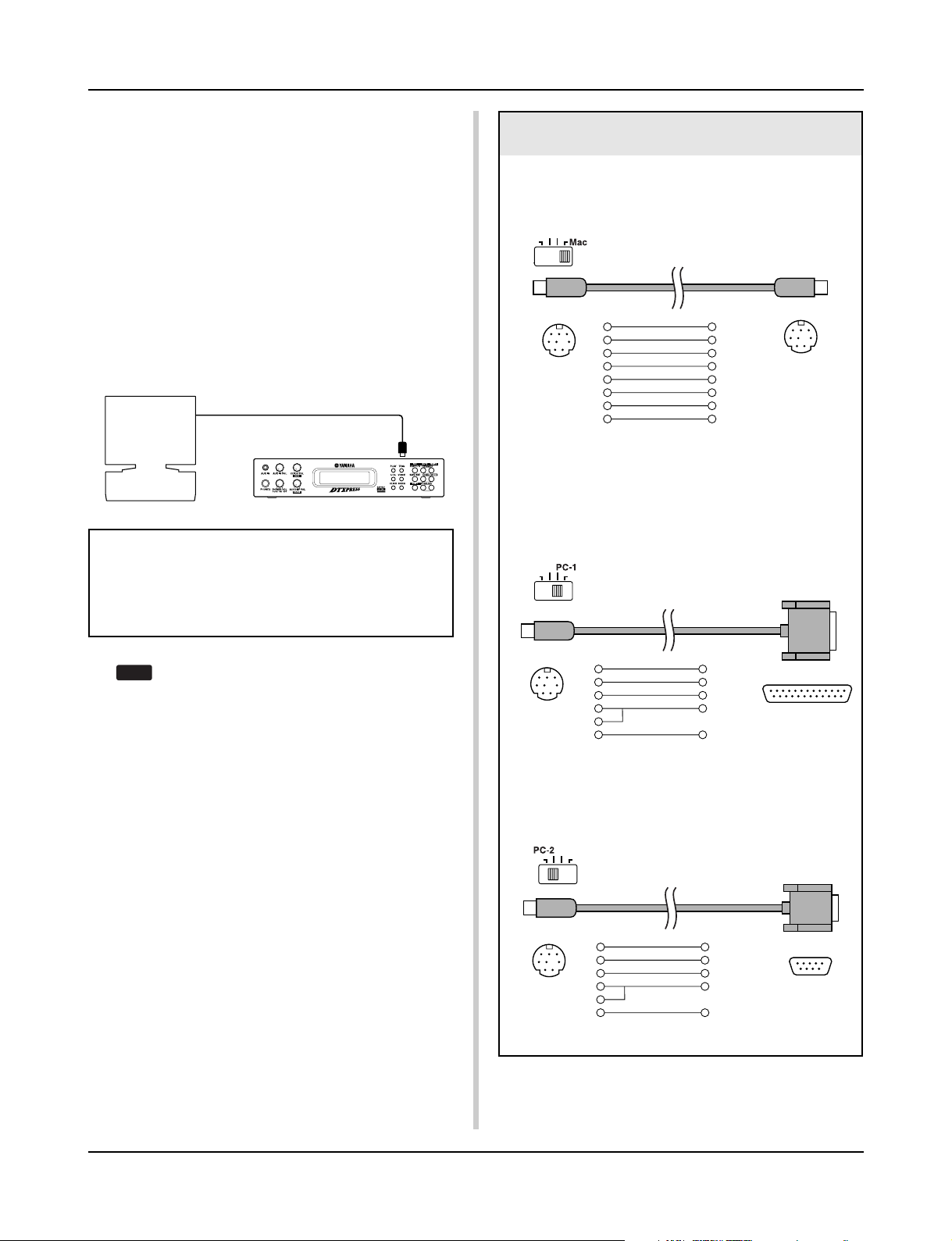
Getting More Out of Your DTXPRESS
■ Connecting a Computer
The following two methods are available for connecting the
DTXPRESS to a computer.
1. Directly connect the computer’s serial port to the
DTXPRESS’ TO HOST jack.
2. Connect the DTXPRESS’ MIDI IN jack to the computer
through a MIDI interface.
1. Directly connect the serial port to the TO
HOST jack.
The method used for connect and transferring signals between a
computer and the DTXPRESS is basically the same, no matter
what type of computer is used.
Computer
Serial Port
Serial Cable
TO HOST
DTXPRESS
Use a cable to connect the devices and set the HOST SELECT SWITCH according to the type of computer serial
port and clock used. Carefully read the instructions on
the right side of this page and select an appropriate cable
for the type of computer you are using.
Computer Connecting Cables
● Mac
Apple Macintosh Peripheral cable (M0197).
Maximum length 2 meters.
mini DIN 8-pin mini DIN 8-pin
2 (HSK i)1
1 (HSK o)2
5 (RxD _)3
4 (GND)4
3 (TxD _)5
8 (RxD +)6
7 (GP i)7
6 (TxD +)8
● PC-1
8-pin MINI DIN to D-SUB 25-pin cable.
If your PC-1 type computer has a 9-pin serial port, use the
PC-2 type cable. Maximum length 1.8 meters.
The input signal from the TO HOST jack will be trans-
HINT
mitted to the DTXPRESS’ tone generator and sequencer, and simultaneously transmitted to the
DTXPRESS’ MIDI OUT jack. At this time, only message for the port number that is set in the Utility mode’s
[2-10. Host Thru Port] (P. 56) will be sent to the MIDI
OUT jack.
The signal from the tone generator and sequencer is
merged with the signal from the MIDI IN jack and
output to the TO HOST jack.
2. Connect the MIDI IN Jack to a MIDI Interface
• If you are using a computer equipped with a MIDI interface,
connect the MIDI OUT jack on the computer to the MIDI IN
jack on the DTXPRESS. Set the HOST SELECT switch to the
“MIDI” position.
• If you are using a Macintosh series computer with an external
MIDI interface, connect the MIDI interface to the computers
RS-422 jack (modem or printer port), connect the MIDI OUT
jack on the interface to the MIDI IN jack on the DTXPRESS.
Set the HOST SELECT switch to the “MIDI’ position.
* When the HOST SELECT switch is set to the “MIDI” position,
the transmission and reception via the TO HOST jack is ignored.
mini DIN 8-pin
5 (CTS)1
4 (RTS)2
3 (RxD)3
7 (GND)4
8
2 (TxD)5
● PC-2
8-pin MINI DIN to D-SUB 9-pin cable.
Maximum length 1.8 meters.
mini DIN 8-pin
8 (CTS)1
7 (RTS)2
2 (RxD)3
5 (GND)4
8
3 (TxD)5
D-SUB 25-pin
D-SUB 9-pin
26
Page 27

Reference
This section describes each function of the DTXPRESS in detail.
You can use it like a dictionary to look up the functions you can’t
understand. Each mode is listed in the same order as they are
displayed in the DTXPRESS.
The Table of Contents (P. 6) and Index (P. 85) will assist in locating functions and lists.
DTXPRESS Internal Makeup .................. 28
Drum Kit Play Mode ................................ 30
About the Song ....................................... 32
Trigger Setup Edit Mode ......................... 35
Drum Kit Voice Edit Mode....................... 39
Song Job Mode ....................................... 48
Utility Mode .............................................. 51
Page 28

DTXPRESS Internal Makeup
■ The DTXPRESS’ Internal Signal Flow
Input for Trigger Signals produced when the pad is struck
Sequencer data
from a computer
or an external
MIDI device.
Record
Song Data
Preset
No. 1-95
User
No. 96-127
Trigger Setup Data Buffer
Record
Playback
Trigger Setup Data
Preset
No. 1-7
User
No. 8-11
Drum Kit Data
Drum Kit Data Buffer
Tone Generator
Transmits key on/off, program
change, note number, etc.
MIDI data to a computer or an
external MIDI device.
Audio Signal Output
● Pad Data Signal Flow
In order for the DTXPRESS to effectively manage trigger signals
transmitted from the pads connected to the Trigger Input Jacks (1
KICK, 2 SNARE, … 9/10) and the HI HAT CONTROL jack, trigger signals are adjusted to a suitable signal in the Trigger Setup
Buffer using the Trigger Setup.
Signals transmitted from the Trigger Setup Buffer will enter the
Drum Kit Buffer.
In the Drum Kit Buffer, the Drum Kit is set as to what voices will
be used and how voices will be delivered for each of the Trigger
Input Sources. The Tone Generator’s Voices will be produced
according to these settings and its audio signal will be transmitted
to the OUTPUT jacks and PHONES jack.
● Trigger Setup Data
This mode is used for adjusting the trigger input, from pads and
trigger sensors connected to the Trigger Input Jacks, to a suitable
signal the sensitivity and velocity curve settings. (The signals characteristics will change according to the strength of the hit.) Also,
cross-talk and double-trigger can be effectively eliminated with
the settings available here.
Copy
Copy
Store
The Tone Generator is sounded according to the Drum Maps
for each of the Drum Kits
• Each Preset Drum Kit has its own Drum Map
• User Drum Kits No. 49-80 use a common (one) Drum Map.
Preset
No. 1-48
User
No. 49-80
Along with 7 preset trigger setups (No. 1-7), there are another 4
user trigger setups (No. 8-11) available for storing original setups.
After selecting a trigger setup for use, the data will be copied to
the Trigger Setup Data Buffer where the copied data will be used
in performance. (Refer to the illustration above.)
Setup data can be freely changed in the Trigger Setup Edit mode
and saved, if necessary, to the User Trigger Setup’s memory (No.
8-11).
● Drum Kit Data
This mode is used for setting drum kit voices, for example, assign
a voice to each pad (trigger input source) used in the drum kit and
perform settings such as selecting the voice, tuning, reverb level,
etc.
The DTXPRESS has 48 preset (No. 1-48) drum kits and another
32 user (No. 49-80) drum kits that are used for saving original
drum kits created by the user.
As in the Trigger Setup, the selected drum kit’s data will be copied
to the Drum Kit Data Buffer where the copied data will be used in
performance. (Refer to the illustration above.) This Drum Kit data
can be freely changed in the Drum Kit Voice Edit mode and saved,
if necessary, to the User Drum Kit’s memory (No. 49-80).
28
Page 29

DTXPRESS Internal Makeup
● Tone Generator
The DTXPRESS’ tone generator contains a total of 910 drum and
percussion voices.
Preset Drum Kits use an exclusive Drum Kit Map for each kit in
which voices for the kit are assigned to individual MIDI note numbers.
The User Drum Kit uses one drum map (User Drum Map) that is
common for all drum kit numbers 49-80. The Utility mode’s [5.
Map (Drum Map)] group can be used to assign voices to each
MIDI note number (0-127) and edit the drum kit.
Along with the DTXPRESS’ drum and percussion voices, the
DTXPRESS possesses a variety of keyboard voices (128 voices)
that are based on the GM System Level 1. It is possible to deliver
piano and brass voices by hitting the pad and playback songs with
the internal sequencer or from external sequencer data. A maximum of 32 voices can be delivered simultaneously.
● Song Data
The DTXPRESS contains 95 preset songs (No. 1-95) that consist
of not only drum parts but also keyboard, brass, etc., accompaniment parts.
You can enjoy the songs as they are or mute the song’s drums or a
single drum voice (snare drum, etc.) and play along with the drum.
Also, you can record your performance to the User Song memory
(No. 96-127). Each song consists of two tracks and each track can
include data for MIDI channels 1-16.
● MIDI/TO HOST Jacks
All drum kit setting data and sequencer data are managed with a
MIDI data.
By connecting the DTXPRESS’ MIDI OUT/IN jacks to the MIDI
IN/OUT jacks on an external MIDI device, MIDI data can be exchanged. The TO/HOST jack is used to transmit and receive MIDI
data from a computer.
According to the MIDI data transmitted from an external MIDI
device or computer connected to the DTXPRESS, drum kits can
be switched, the song can be controlled and the tone generator can
be sounded freely.
For example, song data (sequencer data) transmitted from an external sequencer to the DTXPRESS’ MIDI IN jack can be used to
play the voices produced by the DTXPRESS’ internal tone generator. You can use the DTXPRESS to play along with these songs
and record both external sequencer and DTXPRESS parts.
Also, MIDI data produced when the DTXPRESS can be transmitted to an external MIDI device and/or computer. Playing the
DTXPRESS in this configuration allows you to trigger the external tone generator’s voices and when a drum kit is switched, have
the external MIDI keyboard’s voice change as well. The
DTXPRESS’ data can be stored to, as well as retrieved from an
external MIDI device.
■ Basic Operations for Data Setting
● Enter the Modes
Press each Mode button.
Double-click a button to jump directly to the specified page the
mode you want to enter.
• Drum Kit Play Mode .............................. [PLAY]
• Trigger Setup Edit Mode ....................... [TRIG]
• Utility Mode ........................................... [UTIL]
• Drum Kit Voice Edit Mode .................... [VOICE]
• Song Job Mode ..................................... [SONG]
● Page Navigation
Press the [PAGEs] button to move to the previous page, the
[PAGEt] button to move to the next page. Hold the button to
scroll through the pages.
● Select the Parameter
The flashing parameter on the display is specified for setting.
• Use the [SEL<] and [SEL>] buttons to move the cursor (the
flashing character or symbol).
The [SEL<] button moves the cursor to the left while the
[SEL>] moves the cursor to the right.
•When there is only one parameter on the display, the [SEL<]/
[SEL>] buttons will not operate.
● Change the setting
The setting (value) of flashing parameter on the display can be
changed.
•The [VALUE–] and [VALUE+] buttons are used to set parameter values.
When setting values, press the [VALUE–] button to decrease
(minus) the value, press the [VALUE+] button to increase (plus)
the value. Holding the button will continue to decrease/increase
the value.
Hold the [VALUE–] and press the [VALUE+] button will decrease the value by 10. Continue to hold both buttons and the
value will continue to decrease.
Hold the [VALUE+] button and press the [VALUE–] button to
increase the value by 10. Continue to hold both buttons and the
value will continue to increase.
29
Page 30

Drum Kit Play Mode
HINT
This mode enables you to play the DTXPRESS drum
voices by hitting the pads (or drums with trigger sensors attached) connected to the DTXPRESS.
The DTXPRESS automatically enters this mode when
the power is switched on.
You can select and play from 48 preset drum kits and 32
user kits.
Also, the drum kit, trigger setup and song specified in
this mode will be selected and ready for editing when
the Drum Kit Voice Edit, Trigger Setup Edit and Song
Job modes are entered.
■ Entering the Drum Kit Play Mode
Press the [PLAY] button on the front panel.
Once the Drum Kit Play mode is entered, the Drum Kit & Song
display shown below will appear.
KIT =1 Acoustic
SONG=1 Latiniq
■ What’s in the Drum Kit Play Mode
The Drum Kit Play mode contains the three setting displays shown
below.
1. Drum Kit & Song .................................. (P. 30)
This display is used for selecting the drum kit and
song.
2. Trigger Setup & Tempo ........................ (P. 30)
This display is used for selecting the trigger setup
and song settings.
3. Song & Mute ......................................... (P. 31)
This display is used for selecting the song and
specifying the drum mute during the song.
Procedure
1.
Press the [PLAY] button to enter the drum kit play mode.
2.
Use the [PAGEs]/[PAGEt] buttons to select the page
you want to set.
3.
Use the [SEL<]/[SEL>] buttons to move the cursor to
the parameter you want to set. The parameter will flash.
4.
Use the [VALUE–]/[VALUE+] buttons to set the
parameter’s value.
Press the [SHIFT]+[PAGEt] buttons, in any Drum Kit
HINT
Play mode display, to jump to the Trigger Setup & Tempo
display with the cursor moved to tempo value.
1. Drum Kit & Song
This display is used for selecting the drum kit and song.
KIT =1 Acoustic
SONG=1 Latiniq
q KIT (Drum Kit)
[Range] 1-80
Selects the drum kit. The drum kit number and drum kit name will
be displayed. Preset kits are numbered 1-48 and user kits are numbered 49-80.
When a pad is hit, the selected drum kit voice will be delivered.
Also, this drum kit will be specified for editing when the Drum
Kit Voice Edit mode is entered.
* Once a setting is changed in the Drum Kit Voice Edit mode, “*”
will appear between “KIT” and “=” until the data is stored.
* Refer to the [Preset Drum Kit List] (P. 72)
w SONG
[Range] 1-127
Selects the song. The song number and song name will be displayed. Preset songs are numbered 1-95 and user songs are numbered 96-127.
The selected song will playback when the [START/S] button is
pressed.
* When the rhythm mute ([SHIFT]+[PAGEs] is applied, the last
letter of the song name will be “˚”.
* Refer to [About the Song] (P. 32).
* Refer to the [Preset Song List] (P. 79).
q
w
2. Trigger Setup & Tempo
This display is used for selecting the trigger setup and song settings.
Press the [SHIFT]+[PAGEt] buttons, in any Drum Kit
Play mode display, to jump to the following display with
the cursor moved to tempo value.
TRIG =1 Medium
q
ƒ=110=--= 4/4=ƒ
w e r t
q TRIG (Trigger Setup)
[Range] 1-11
Selects the trigger setup to be used. The trigger number and trigger name will be displayed. Presets are numbered 1-7 and user
setups are numbered 8-11.
*For more information on the preset trigger setup, refer to the
[Trigger Setup List] (P. 79).
* Once a setting is changed in the Trigger Edit mode, “*” will ap-
pear between “TRIG” and “=” until the data is stored.
w q (Tempo)
[Range] 30-300, ext
Sets the playback tempo for the song.
30
Page 31

HINT
Drum Kit Play Mode
When the DTXPRESS is controlled by an external sync, “ext”
will be displayed.
* The external sync setting is found in [3-6. Sync Mode] (P. 57).
e Repeat Playback
[Range] —, rp
Sets the repeat playback (repeat continuously from the beginning
to the end of the song) of the song.
When this parameter is set to “rp”, the song will repeat playback.
When this parameter is set to “--”, the song will playback normally.
r Beat
[Range] 1/4-8/4, 1/8-16/8, 1/16-16/16
Sets the beat of the song (metronome).
t Metronome Note Value
[Range] When the beat r is set to 3/8, 6/8, 9/8, 12/8, 15/8, the
click tempo will be set to
ƒ quarter note, © eighth note, ˙ sixteenth note.
When the beat r is set to any value that is not listed
above, the click tempo will be set to
ƒ quarter note, ƒ3 quarter note (triplet),
© eighth note, ©3 eighth note (triplet),
˙ sixteenth note, ˙3 sixteenth note (triplet).
Use the note values to set the click tempo of the metronome.
3. Song & Mute
This display is used for selecting the song and specifying the drum
mute during the song.
Drum Voice Category Mute Classification
K, k Ki (kick)
S, s Sn (snare)
C, H Cy (cymbal)
T, t, P, E, e, L, m Mi (others)
Since drum voices for pads (triggers) are not muted you
can, for example, mute the snare voice of a song and practice the snare part along with song playback (the snare
voice is delivered when the pad is hit).
Groove Check Function
Function
As you play the pads along with a song, the DTXPRESS will
compare your performance with its song clock and let you
know how accurate your timing is.
Display
In the Drum Kit Play mode (from any display) press the
[SHIFT]+[SEL>] (GRV) buttons.
* The Groove Check function will quit when song playback
is stopped.
* The top line of the original page is displayed as is.
SONG=1 Latiniq
q
Ki=®Sn=mCy=®Mi=®
w
q SONG
[Range] 1-127
Selects the song. The song number and song name will be displayed.
Press the [SONG] button to start playback of the selected song.
* This song select operation is the same as in [1. Drum Kit and
Song]. The only difference is whether the display will switch or
not when the Groove Check is used.
w Drum Mute
[Range] m (mute; Does not produce sound), ® (Produces sound)
Sets the type of drum voice to be muted. The 4 types of voices that
can be muted are Ki (kick), Sn (snare), Cy (cymbal) and Mi (others).
* Drum voice types
Drum voices are divided into many groups (categories) in accordance with the type of sound i.e. kick, snare, etc. For more
information on Drum Voice categories, refer to the [Drum Voice
List] (P. 68).
KIT =1 Acoustic
Groov= 0Ave= 0
q w
Setting
q Groov (Groove)
[Range] –48 to 0 to +48
The difference in the timing of each stroke on the pad is displayed.
If the timing of the stroke is late compared to the just time, a
minus value will be displayed. If your timing is early, a plus
value will be displayed. If you timing is perfect, “0” will be
displayed.
w Ave (Average)
[Range] –48 to 0 to +48
This function displays the average value of your timing accuracy after the Groove Check function is switched ON.
This function checks your performance on the entire drum
set and can check your performance on one song. The information shown in the display is the same as in q Groov.
*To reset the data, press the [SHIFT]+[SEL>] buttons twice.
31
Page 32

About the Song
The DTXPRESS can internally store data for a maximum of 127
songs that can be played back freely.
Song numbers 1-95 are preset songs and song data in those songs
cannot be changed or rewritten.
Song numbers 96-127 are user songs that can be used to record
new performance data and also edit song data in.
■ Song Makeup
The Song consists of two sequencer tracks plus header data.
Header data is written at the front of the song and holds information related to the song’s tempo, beat, program numbers (voice)
for each MIDI channel and volume, etc. Header data is read every
time the song is played from the beginning.
Both tracks possess data for MIDI channels 1-16 (except system
exclusive data).
Durring song playback, the sequencer data that is written in the
song will be transmitted to the DTXPRESS’ tone generator to produce the song.
■ Main Song and Pad Song
Up to four songs can be played back simultaneously.
The song that is selected in the Drum Kit Play mode (P. 30) is
called the Main Song. Pressing the [START/S] button will start
playback of this song.
The remaining three songs are called Pad Song(s). These songs
are played back according to the trigger input (hitting a pad).
■ Metronome
The sequencer produces the metronome.
The metronome can be used either alone or with the Song.
Press the [CLICK] button, in any mode, to start the metronome.
The metronome’s tempo, voice, etc. are set in the Utility mode [3.
Sequencer Group] (P. 56).
Song Playback
■ Main Song Playback
• Select a Song
1.
Press the [PLAY] button to enter the Drum Kit Play mode.
Use the [PAGEs]/[PAGEt] buttons to display either of
the displays shown below (Drum Kit & Song or Song &
Mute).
• Drum Kit & Song
KIT =1 Acoustic
SONG=1 Latiniq
• Song & Mute
SONG=1 Latiniq
Ki=®Sn=®Cy=®Mi=®
2.
Use the [SEL<]/[SEL>] buttons to move the cursor to
the “SONG=” position.
3.
Use the [VALUE–]/[VALUE+] buttons to set the song number of the song you want to playback.
• Set the Tempo, Repeat Playback, Beat and Metronome
1.
In the Drum Kit Play mode, use the [PAGEs]/[PAGEt]
buttons to display the “Trigger Setup & Tempo” display
shown below.
TRIG =1 Medium
ƒ=120=--= 4/4=ƒ
2.
Use the display shown above to set the Tempo, Repeat
Playback, Beat and Metronome Note Value.
32
• Song Playback (Start/Stop)
Press the [START/S] button, in any display, to start playback of
the song (main song).
During playback, press the [START/S] button to stop playback of
the song. Press the [START/S] button again and the song will start
playback from the beginning.
* If the pad’s function is previously set to the “Main Song Control”
function (m Drum Kit Voice Edit Mode [2-6. Function] P. 44), you
can start/stop the main song by hitting the assigned pad.
* During song playback, the [SONG] button’s LED will light for a
moment at the beginning of each measure.
* During song playback, the song cannot be changed.
* If the song’s tempo or voices are irregular, re-select the song.
Page 33

About the Song
■ Pad Song Playback (Start/Stop)
To playback a Pad Song, hit the pad that is assigned to the Pad
Song you want to playback. Hit the same pad during playback will
stop the song. Hit the pad again to start the song from the beginning.
* Before using, set the pad’s function to “Pad Song Control” and
assign a song to the pad (m Drum Kit Voice Edit mode [2-6.
Function], [2-7. Pad Song] P. 44).
* The song can be played one measure at a time, each measure
triggered with a stroke on the pad (m Drum Kit Voice Edit mode
[2-7. Pad Song] P. 44)
* If the Pad Song’s tempo or voices are irregular, re-select the
Drum Kit.
■ Song Playback Functions
During song playback, the song can be repeated and volume levels for each instrument can be changed.
• Volume Control
With each of the knobs on the front panel, the following volume
levels can be controlled.
• [ACCOMP VOL]: The volume of the accompaniment (excluding percussion voices).
• [SHIFT]+[ACCOMP VOL]: The volume of the snare drum.
• [CLICK VOL]: The volume of the metronome’s click.
• [SHIFT]+[CLICK VOL]: the volume of the bass drum.
• Rhythm Mute Function
When the [SHIFT]+[PAGEs] buttons are pressed, the MIDI channels (usually channel 10) that are assigned to track 1 of the song
and the drum voice will be muted (sound will not be delivered).
* When the Rhythm Mute is applied, program changes will be ig-
nored so the drum kit cannot be changed.
• Other Functions
• This function can set whether the song will playback according to the tempo information in the song or according to the
tempo that is set when the song is switched. (m P. 58 [3-7.
Use Tempo])
• This function can set whether or not the click voice will be
delivered automatically when the song is played back. (m P.
58 [3-8. Click Mode])
•The metronome’s click voice can be switched ON/OFF by hitting the pad. (m P. 44 [2-6. Function])
If the Utility mode’s [1-3. Volume Mode] (P. 52) is set to “live”,
the following volume levels can be controlled.
• [ACCOMP VOL]: The volume of the snare drum.
• [SHIFT]+[ACCOMP VOL]: The volume of the cymbal.
• [CLICK VOL]: The volume of the bass drum.
• [SHIFT]+[CLICK VOL]: The volume of the other drum instruments (excluding snare, bass drum, cymbals and the
metronome’s click).
• Set the Metronome
The voice, pitch and MIDI note number of the metronome’s click
voice can be set. ([3-1. Click Voice] (P. 56), [3-2. Click Tune] (P.
57), [3-3. Click Note Number] (P.57)
• Count Function
If the Utility mode’s [3-5. Count Switch] (P. 57) is set to “on”
when the main song is played back, the first measure of the song
will be preceded by a two measure count.
• MIDI Control by an External Device
• If the Utility mode’s [3-4. MIDI Control] (P. 57) is set to “on”,
playback of the main song can be controlled with system realtime messages (start/continue/stop) from the MIDI IN/TO
HOST jack.
• If the Utility mode’s [3-6. Sync Mode] (P. 57) is set to “ext”
or “auto”, the song playback can be synchronized to the clock
of an external MIDI device.
33
Page 34

About the Song
Song Recording
Song recording lets you record data, produced as the drum kit is
played, to the sequencer in real-time (one track at a time). All MIDI
channels (1-16) are recorded simultaneously. Also, data produced
by a MIDI keyboard connected to the MIDI IN jack can be recorded as well as sequencer data received via the MIDI IN/TO
HOST jacks.
According to the recorded sequencer data (performance information), drum kits and voices can be changed during song playback.
The songs that are recorded can be played back and edited in the
same manner as preset songs (No. 1-48) with the Song Job mode.
■ Song Record Settings
• Select the Song
1.
Press the [PLAY] button to enter the Drum Kit Play mode,
set the User Song number (No. 96-127) that you want to
record to.
* Only User Songs (No. 96-127) can be used for recording.
Preset Songs (No. 1-95) cannot be used for recording.
• Set the Recording Conditions (Record Standby)
2.
Press the [SHIFT]+[START/S] buttons, the record mode
will be in standby. The following display will appear.
q w e
REC M= 32=Rp1†=1
ƒ=120 B= 4/4Q=©
r y
3.
Use the display shown above to set the following recording conditions.
q M (the number of measures that will be recorded)
[Range] 1-999
Assigns the number of measures that will be recorded. When
there is data in the other track, the number of measures in that
track will decide the length of the song and this length cannot
be changed.
w Record Mode
Select the method of recording from the following.
Overwrite (Ovr): The record operation will be in a repeat
mode. When the song reaches the end of the last measure, it
will automatically start again from the beginning and new
data will be added to the track’s previous data.
Replace (Rpl): When the song reaches the end of the mea-
sure number assigned in “M” or the [START/S] button is
pressed, recording will stop (the song will not repeat).
e TR (Specify the Track for Recording)
Selects which track (“1” or “2”) will be recorded.
r q (Metronome Tempo) [Range] 30-300
Sets the metronome tempo for recording
t B (Beat) [Range] 1/4-8/4, 1/8-16/8, 1/16-16/16
Sets the beat of the song (metronome) for recording.
t
y Q (Quantize Accuracy)
[Range] ƒ quarter note, ƒ3 quarter note (triplet)
© eighth note, ©3 eighth note (triplet)
˙ sixteenth note, ˙3 sixteenth note (triplet), no
The Quantize function* can be used when recording.
When set to “no”, the Quantize function will not operate.
Quantize: This function is used to correct the timing of recorded
MIDI note data. The accuracy of quantization is assigned
by the note value.
*You can also use the Quantize function after recording is com-
plete. (Song Job mode [5. Quantize] P. 49)
• Record
4.
Press the [START/S] button to start recording.
* If the Utility mode’s [3-4. MIDI Control] (P. 57) is set to “on”,
the recording operation can be started with a system real
time message (start) received via the MIDI IN/TO HOST jacks.
* When the track assigned for recording contains data and the
[START/S] button is pressed, the error message “Data not
Empty” will appear and the recording operation will not be
carried out.
While the song is recording, the following display will appear
(only displayed, cannot change).
• When the Record Mode = Replace (“Rpl”)
REC M= 5=Rp†=1
Now Recording.
• When the Record Mode = Overwrite (“Ovr”)
REC M= 5=Ovr†=1
UNDO press ENT
•Next to “M=” the measure number currently being recorded is
displayed.
• When the Record mode is set to “Ovr”, press the [SAVE/
ENT] button to “Undo” (do again) the record operation. Press
the [SAVE/ENT] button while recording to start recording from
the top of the song. The data previously recorded from the
beginning of the song, up until the [SAVE/ENT] button was
pressed, will revert to the data originally present.
• Stop Recording
5.
When the song reaches the end of the assigned measure number, recording will automatically stop and the
DTXPRESS will return to the Drum Kit Play mode (Drum
Kit & Song display).
* Recording can also be stopped anytime by pressing the
[START/S] button.
* If the power is switched off while recording, all the data in the
User Song may be lost. Please use caution.
Data recorded in the tracks cannot be overwritten. To
record new data, use the Song Job mode’s [6. Clear Track]
(P. 50) or [8. Clear Song] (P. 50) operations to erase tr ack
data.
34
Page 35

Trigger Setup Edit Mode
This mode contains various settings related to trigger
input from the pads and trigger sensors that are connected to the DTXPRESS.
It allows you to adjust pad sensitivity and assign drum
voices to each trigger input. Trigger Setup data consists
of seven preset types (No. 1-7) and four original setup
types (No. 8-11) for storing user setup data.
■ What you can do with the Trigger Setup Edit
Mode
The Trigger Setup Edit Mode lets you alter a variety of settings for
each of the trigger inputs jacks (1-10) of the Trigger Setup.
You can edit both preset (No. 1-7) and user Trigger Setups (No. 8-
11).
The edited Trigger Setup can be stored in a User Trigger Setup
(No. 8-11) using the Store Operation.
* Selecting another Trigger Setup before storing your changes
will result in the data reverting to its default settings.
* Data cannot be stored to preset Trigger Setup (No. 1- 7).
■ Entering the Trigger Setup Edit Mode
Press the [TRIG] button on the front panel.
Once the Trigger Setup Edit Mode is entered, the INPUT
parameter’s main page (pad type), shown below, will be displayed.
5.
Use the [VALUE–], [VALUE+] buttons to set the
parameter’s value or ON/OFF setting.
* Once a setting is changed, “*” will appear on the display next
to “TRIG”. After data is saved, the mark will disappear.
TRIG*IN= 1
Type= KP
6.
To store changes in the User Trigger Setup, use the following procedure.
* The changes you made will be lost if another trigger setup is
selected before your changes have been stored.
6-1. Press the [SAVE/ENT] button. The following display will
appear.
Store Trigger
To= 8 InitTrig
6-2. Use the [VALUE–], [VALUE+] buttons to assign the User
Trigger Setup number (8-11) (located next to “To=”) for
storing your changes. The number and setup name will
appear.
6-3. Press the [SAVE/ENT] button, the following display will
appear asking for confirmation before the store operation is carried out.
TRIG IN= 1
Type= KP
* Double-click the [TRIG] button to enter the Trigger Setup Edit
Mode. The [1-2. Gain, Minimum Velocity] display will appear.
■ What’s in the Trigger Setup Edit Mode
The Trigger Setup Edit Mode is divided into two sub-groups.
1. INPUT Parameters ............................... mP. 3 6
Contains specific settings for each pad (1-10).
2. COMMON Parameters ......................... mP. 3 8
Contains common settings for all pad inputs.
Procedure
1.
Before editing, it is necessary to select the trigger setup
you want to edit in the drum kit play mode [Trigger Setup
& Tempo].
2.
Press the [TRIG] button to enter the Trigger Setup Edit
mode.
3.
Use the [PAGE▲], [PAGE▼] buttons to display the list
you want to edit.
* If the Utility mode’s [Jump to Recent Page] parameter (P. 28)
is set to “on”, the DTXPRESS will display the page last edited when entering the Trigger Setup Edit mode.
4.
Use the [SEL<], [SEL>] buttons to move the cursor to
the list you want to edit. The list will flash.
* If there is only one list, it is not necessary to move the cursor.
Store TRG to 8
Are you sure ?
6-4. Press the [SAVE/ENT] or [VALUE+] button, the store
operation will be carried out.
*Press the [VALUE–] button to cancel the store opera-
tion.
The following display will appear after the store operation is completed.
Complete !
Trigger Setup Edit Mode Function List
Page
1. INPUT Parameters .................................................. 36
1-1. Pad Type .......................................................... 36
1-2. Gain, Minimum Velocity ................................... 36
1-3. Velocity Curve ................................................. 37
1-4. Self Rejection, Rejection ................................. 37
1-5. Specific Rejection ............................................ 37
1-6. Copy Input ....................................................... 37
2. COMMON Parameters ............................................ 38
2-1. Increment/Decrement ...................................... 38
2-2. Input Exchange ............................................... 38
2-3. Trigger Setup Name ........................................ 38
35
Page 36

Trigger Setup Edit Mode
1. INPUT Parameters
Contains specific settings for each of the pads (1-10).
This function is divided into the following 6 pages.
1-1. Pad Type .......................................................... 36
1-2. Gain, Minimum Velocity ................................... 36
1-3. Velocity Curve ................................................. 37
1-4. Self Rejection, Rejection ................................. 37
1-5. Specific Rejection ............................................ 37
1-6. Trigger Setup Copy .......................................... 37
1-1. Pad Type
Sets the type of pad or trigger sensor that is connected to the trigger input jack q. By selecting the appropriate pad type, pad functions can be used to their full potential.
TRIG IN= 1
Type= KP
q TRIG IN (Trigger Input Number)
[Range] 1-10
Assigns the trigger input jack number for the pad you want to edit.
* According to the setting in the utility mode’s [1-1. Learn Mode]
(P. 52) trigger input jack numbers can be assigned by hitting the
pad.
w Type (Pad Type)
Sets the type of pad that is connected to the trigger input jack
assigned in q TRIG IN.
*Values set in [1-2. Gain, Minimum Velocity] (P. 36) and [1-4. Self
Rejection] (P. 37) will automatically select the proper value for
the pad type you set here.
* The “ HH contrler” can only be assigned to Input Jack 1. Con-
nect the Hi-hat Controller HH60, HH80 or HH80A to Input Jack
1 and set to “HH contrler” to use in place of a kick pedal.
Use a cable with a stereo plug when connecting a Hi-hat controller.
Pad types are defined as follows.
TP snare TP60, TP80, TP80S used as a snare pad.
TP tom TP60, TP80, TP80S used as tom pads.
TP HH TP60, TP80, TP80S used as a hi-hat pad.
KP KP60, KP80, KP80A used.
PCY ride PCY60, PCY80, PCY80S used as ride cymbal
pads.
PCY crash PCY60, PCY80, PCY80S used as crash cymbal
pads.
PCY cup PCY10, etc. used as the cymbal cup.
BP BP80 used.
DT snare DT10, DT20 attach to the snare drum.
DT hi tom DT10, DT20 attach to small toms
DT lo tom DT10, DT20 attach to large toms
DT kick 1 DT10, DT20 attach to small bass drum
DT kick 2 DT10, DT20 attach to large bass drum
misc 1 Extensive use1—high sensitivity type.
Rim switch function is good for snare/tom use.
q
w
misc 2 Extensive use 2—high sensitivity type.
Rim switch function is good for cymbal use.
misc 3 Extensive use 3—normal sensitivity type.
Rim switch is good for snare/tom use.
misc 4 Extensive use 4—normal sensitivity type.
Rim switch function is good for cymbal use.
misc 5 Extensive use 5—low sensitivity type.
Rim switch is good for snare/tom use.
misc 6 Extensive use 6—low sensitivity type.
Rim switch function is good for cymbal use.
HH contrler
* The DT10, DT20 are Yamaha Drum Trigger Sensors.
Connect the HH60, HH80, HH80A to Trigger In-
put jack 1 to use as a kick pedal.
* The volume (velocity) is fixed.
1-2. Gain, Minimum Velocity
This function sets the input sensitivity (Gain) and velocity range
(Minimum Velocity) for each input jack q.
q
TRIG IN= 1 ( 0%)
Level Display
Gain=64 MVel= 32
w
q TRIG IN (Trigger Input Number)
Assigns the trigger input jack number. (The same procedure as in
[1-1. Pad Type]).
w GAIN (Input Gain)
[Range] 0-99
Adjusts the input gain level (minimum sensitivity) for the trigger
input jack assigned in step q TRIG IN.
Entering a larger value here allows smaller input levels to sound
the voice.
* This value will be automatically set after the appropriate pad
type is set in [1-1. Pad Type]. Some fine-tuning of the value will
be necessary.
e MVel (Minimum Velocity)
[Range] 1-127
Sets the MIDI Velocity (volume) that is transmitted when the pad
is hit the weakest. Large values will produce a high volume level
even if the pad is hit softly. However, this will result in a narrow
volume range making it difficult to adequately produce wider dynamic levels.
If “
HH contrler
be transmitted as the velocity.
The trigger input level will be displayed as a % in the upper right
hand corner of the display. The maximum velocity (input level
99%) will be 127. The level is low when the pad is hit the weakest
so a wider dynamic range will be possible.
* This value will be automatically set after the appropriate pad
type is set in [1-1. Pad Type]. Some fine-tuning of the value will
be necessary.
” is set for the pad type, the value set here will
e
36
Page 37

Trigger Setup Edit Mode
1-3. Velocity Curve
This function sets the MIDI Velocity Curve for the sensitivity for
each input jack q.
TRIG IN= 1
VelCurve= normal
q TRIG IN (Trigger Input Number)
Assigns the trigger input jack number (the same procedure as in
[1-1. Pad Type]).
w VelCurve (Velocity Curve)
Sets the Input Velocity Curve for the trigger input jack assigned in
TRIG IN q.
normal hard 2hard 1loud1loud 2
Velocitym
Strength
of hitm
q
w
1-4. Self Rejection, Rejection
This function is used to prevent double triggers* and cross talk
(mixed input signals between the jacks) for each input jack q.
* double trigger: When 2 sounds are played at the same time.
TRIG IN= 1
q
SelfRej=2 Rej= 3
w e
1-5. Specific Rejection
This function prevents cross talk from occurring between two specified input jacks q and e.
TRIG IN= 1
q
SPCRej=0 frm= 1
w
q TRIG IN (Trigger Input Number)
Assigns the trigger input jack number (the same procedure as in
[1-1. Pad Type]).
w SPCRej (Specific Rejection)
[Range] 0-9
After an event occurs from the pad from the input jack assigned in
e, the pad of the input jack assigned in TRIG IN q will not
sound for a certain length of time unless the level is greater than
the value assigned here.
e frm (Assigned Destination Trigger Input Number)
[Range] 1-10, 6&7
Sets the destination trigger input jack number of the pad that will
be rejected. When “6&7” is selected, both trigger inputs 6 and 7
will be assigned.
1-6. Trigger Setup Copy
This function copies all data settings in [1-1. Pad Type] to [1-5.
Specific Rejection] from input jack q to another input jack w.
TRIG IN= 1
Copy to Input= 1
e
q
w
q TRIG IN (Trigger Input Number)
Assigns the trigger input jack number (the same procedure as in
[1-1. Pad Type]).
w SelfRej (Self Rejection)
[Range] 0-9
Prevents double triggers from occuring in the input jack assigned
in TRIG IN q. After an event is detected, further events will be
automatically muted for a certain length of time. Larger values set
longer times.
e Rej (Rejection)
[Range] 0-9
Prevents cross talk from occuring in the input jack assigned in
TRIG IN q. Events triggered by other pads (input jacks) that are
of a lower input value than what is set here will not be delivered
for a set length of time.
When the Trigger Setup Copy operation is carried
out, the trigger setup data will be replaced with the
settings of the copy source.
q TRIG IN (Trigger Input Number)
Sets the trigger input jack number (1-10) of the pad copy source.
w Copy to Input (
Sets the trigger input jack number (1-10) of the copy destination.
Trigger Input Number Copy Destination
Procedure
1.
In the display shown above, assign the copy source and
copy destination, press the [SAVE/ENT] button. The following display will appear asking for confirmation before
the copy operation is carried out.
Input Copy to 1
Are you sure ?
2.
Press the [SAVE/ENT] or [VALUE+] button, the copy
operation will be carried out.
* Press the [VALUE-] button to cancel the copy operation.
When the copy operation is complete, “Complete!” will appear.
37
)
Page 38

Trigger Setup Edit Mode
2. COMMON Parameters
Contains common settings for all pad inputs (1-10).
This group is divided into the following 3 pages.
2-1. Increment/Decrement ...................................... 38
2-2. Input Exchange ............................................... 38
2-3. Trigger Setup Name ........................................ 38
2-1. Increment/Decrement
This sets the pad function that allows the currently selected drum
kit number to be increased or decreased by 1 by hitting the specified pad.
TRIG Common
IncIn= 4DecIn= 5
q w
q Incin (Pad for Increment)
[Range] —, 1-10
Assigns the trigger input jack number that is set for the increment
(+1) function. “--” will appear when this function is not assigned
to the pad.
w Decin (Pad for Decrement)
[Range] —, 1-10
Assigns the trigger input jack number that is set for the decrement
(-1) function. “--” will appear when this function is not assigned
to the pad.
*Even when the drum kit is changed, the pads connected to the
assigned trigger input jacks will retain their increment/decrement functions. To assign this function to each drum kit, refer to
the Drum Kit Voice Edit mode’s [2-6. Function] (P. 44)
When the input jack 9 pad is hit.
m This event will be recognized as a signal from the input jack
1 pad (as if a trigger were received from input jack 1) and
operate accordingly.
When the input jack 10 pad is hit.
m This event will be recognized as a signal from the input jack
9 pad (as if a trigger were received from input jack 9) and
operate accordingly.
2-3. Trigger Setup Name
Changes the name of the currently selected (currently being edited) Trigger Setup.
TRIG Common
TrgName=Medium
q TrgName (Trigger Setup Name)
Procedure
1.
In the display shown above, use the [SEL<]/[SEL>] buttons to move the cursor to the character you want to
change.
2.
Use the [VALUE–]/[VALUE+] buttons to select the alphabet, number or symbol.
3.
Repeat steps 1 and 2 above to create the Trigger Setup
name using a maximum of 8 characters.
● The available characters to choose from are (in order):
space
!"#$%&'()*+,-./0123456789:;<=>?@
ABCDEFGHIJKLMNOPQRSTUVWXYZ[\]^_`
abcdefghijklmnopqrstuvwxyz{|}ßå
q
2-2. Input Exchange
Switches the trigger signal from the pads between trigger input
jacks 1 and 9/10.
TRIG Common
In Excg= normal
q In Excg (Input Exchange)
normal: Normal operation.
In10,1/9: The signals from Input Jacks 1 and 9/10 are switched.
When the input jack 1 pad is hit.
m This event will be recognized as a signal from the input jack
10 pad (as if a trigger were received from input jack 10) and
operate accordingly.
When the input jack 1 rim is hit.
m Normal operation. This event will be recognized as a signal
from the input jack 1 rim.
38
q
Page 39

Drum Kit Voice Edit Mode
This mode lets you set which voice and how it will be
triggered for each pad (trigger input source) in the currently selected drum kit.
■ What you can do with the Drum Kit Voice
Edit Mode
This mode contains various settings related to the currently selected drum kit (data in the edit buffer for the drum kit).
You can edit both preset (No. 1-48) and user drum kits (No. 49-
80).
The edited drum kit can be stored in a User Drum Kit (No. 49-80)
using the Store Operation.
* Selecting another drum kit before storing your changes will re-
sult in the data reverting to its default settings.
* Data cannot be stored to preset drum kits (No. 1- 48).
■ Entering the Drum Kit Voice Edit Mode
Press the [VOICE] button on the front panel.
Once the Drum Kit Voice Edit Mode is entered, the Voice Parameter main page (Voice) shown below will be displayed.
KIT IN=pad 1 V=1
=K/017 BDaftty1
* Double-click the [VOICE] button to enter the Drum Kit Voice Edit
Mode. The [1-2. Volume, Pan] display will appear.
■ What’s in the Drum Kit Voice Edit Mode
The Drum Kit Voice edit Mode is divided into the following five
sub-groups.
1.Voice Parameters .............................. (m P. 40)
Sets the voice for each input source of the pad.
2. Input Common Parameters ............. (m P. 43)
Common settings related to the 2 layers for each
pad input source’s voice parameter.
3. Reverb Parameters .......................... (m P. 45)
Sets the internal reverb effect.
4. Setup................................................. (m P. 46)
When the drum kit is selected, this function copies the drum kit voice settings and MIDI transmit
settings.
5. Drum Kit Common Parameters ...... (m P. 47)
Common settings for the entire drum kit.
3.
Use the [PAGEs], [PAGEt] buttons to display the page
you want to edit.
* If the Utility Mode’s [1- 4. Jump to Recent Page] (P. 52) pa-
rameter is set to “on”, the DTXPRESS will display the page
last edited when entering the Drum Kit Voice Edit Mode.
4.
Use the [SEL<]/[SEL>] buttons to move the cursor to
the parameter you want to edit. The parameter will flash.
* If there is only one parameter, it is not necessary to move the
cursor.
5.
Use the [VALUE–]/[VALUE+] buttons to set the
parameter’s value or ON/OFF setting. Pressing the
[VOICE] button lets you listen to the Drum Kit Voice while
editing.
* Once a setting is changed, “*” will appear on the display next
to “KIT”. After data is stored, the mark will disappear.
KIT*IN=pad 1 V=1
=K/019 MapleA20
6.
To store your changes in a User Drum Kit, use the Store
Operation described below.
* The changes you made will be lost if another drum kit is se-
lected before your changes have been stored.
6-1. Press the [SAVE/ENT] button. The following display will
appear.
Store Drumkit
To= 49 Init Kit
6-2. Use the [VALUE-]/[VALUE+] buttons to assign the Drum
Kit number (49-80) (located next to “To=”). The number and drum kit name will appear.
6-3. Press the [SAVE/ENT] button, the following display will
appear asking for confirmation before the store operation is carried out.
Store KIT to= 49
Are you sure ?
6-4. Press the [SAVE/ENT] or [VALUE+] button, the store
operation will be carried out.
*Press the [VALUE-] button to cancel the store opera-
tion.
Procedure
1.
Before editing, it is necessary to select the drum kit you
want to edit in the Drum Kit Play Mode of the [Drum Kit &
Song] display.
2.
Press the [VOICE] button to enter the Drum Kit Voice
Edit Mode.
The following display will appear after the store operation is complete.
Complete !
39
Page 40

Drum Kit Voice Edit Mode
Drum Kit Voice Edit Mode Function List
Page
1. Voice Parameters .................................................... 40
1-1. Voice................................................................ 41
1-2. Volume, Pan .................................................... 41
1-3. Tuning .............................................................. 41
1-4. Layer Balance.................................................. 42
1-5. Decay, Cutoff Frequency ................................. 42
1-6. Note Number ................................................... 42
1-7. Channel, Gate Time ........................................ 42
2. Input Common Parameters .................................... 43
2-1. Cross Fade ...................................................... 43
2-2. Reverb Send.................................................... 43
2-3. Alternate Group, Key Assign Mode ................. 43
2-4. Hold Mode ....................................................... 44
2-5. Key Off Enable ................................................ 44
2-6. Function........................................................... 44
2-7. Pad Song......................................................... 44
2-8. Rim to Pad....................................................... 45
3. Reverb Parameters ................................................. 45
3-1. Reverb Type, Time ........................................... 45
3-2. Reverb Master Return ..................................... 45
4. Setup ....................................................................... 46
4-1. Program Change, Bank Select ........................ 46
4-2. Volume, Pan .................................................... 46
4-3. Drum Kit Voice Copy ....................................... 46
5. Drum Kit Common Parameters ............................. 47
5-1. Volume ............................................................ 47
5-2. Drum Reverb Send.......................................... 47
5-3. Hi-Hat Sensitivity ............................................. 47
5-4. Song Select ..................................................... 47
5-5. Drum Kit Name ................................................ 47
1. Voice Parameters
Sets the voice for each input source of the pad.
The Input Source is trigger data that is transmitted by the pads or
trigger sensors connected to input jacks 1-10 of the DTXPRESS.
When monaural pads TP60/80, KP60/80, PCY60/80, DT10/20,
etc. are used, one Input Source will be assigned to one input jack.
When stereo pads TP80S, PCY80S, etc. are used, two Input Sources
(pad input and rim switch input or 2 kinds of pad input, etc.) will
be assigned to one input jack.
The Voice Parameter is divided into the following 7 pages.
1-1. Voice................................................................ 41
1-2. Volume Pan ..................................................... 41
1-3. Tuning .............................................................. 41
1-4. Layer Balance.................................................. 42
1-5. Decay, Cutoff Frequency ................................. 42
1-6. Note Number ................................................... 42
1-7. Channel, Gate Time ........................................ 42
Select the Input Source for Editing
In Voice Parameter edit display, first it is necessary to select the
input source q for editing.
Also, 2 voices/key on events/occurrences (2 voices delivered with
one strike of the pad) can be assigned to one trigger input. This use
is called “2 layer”. When a 2 layer is used, assign the layer number
w that is used.
q w
KIT IN=pad 1 V=1
=K/019 MapleA20
q IN (Input Source)
Each Input Source is defined as follows.
pad 1 Pad input for Trigger Input Jack 1.
rim 1 Rim switch input for Trigger Input Jack 1.
pad 2 Pad input for Trigger Input Jack 2.
rim 2 Rim switch input for Trigger Input Jack 2.
::
rim 6 Rim switch input for Trigger Input Jack 6.
pad 7 Pad input for Trigger Input Jack 7.
rim 7 Rim switch input for Trigger Input Jack 7.
open Pad input (when the hi-hat controller is not fully closed)
for Trigger Input Jack 8.
rimOpen Rim switch input (when the hi-hat controller is not fully
closed) for Trigger Input Jack 8.
close Pad input (when the hi-hat controller is fully closed)
for Trigger Input Jack 8.
rimCls Rim switch input (when the hi-hat controller is fully
closed) for Trigger Input Jack 8.
footCl Event when the hi-hat controller is depressed for Trig-
ger Input Jack 8.
splash Splash event for the hi-hat controller for Trigger Input
Jack 8.
40
Page 41

Drum Kit Voice Edit Mode
pad 9 Pad input for Trigger Input Jack 9.
pad 10 Pad input for Trigger Input Jack 10.
*According to the setting in the Utility Mode’s [1-1. Learn Mode]
(P. 52), the input source can be assigned by hitting the pad.
* Monaural pads do not have a rim switch function.
w Layer Number
[Range] 1, 2, -
When 2 layers are used, use this setting to select which layer (“1”
or “2”) will be set.
When only 1 voice is set, “--” will appear and you will not be
able to switch.
* Use the [1-1. Voice] display to set whether 2 layer or 1 voice will
be used.
If the same MIDI note number is set to more than one pad
within the same drum kit, the lowest numbered Trigger
Input Jack will take priority. Regardless of which pad is
struck, the same voice (setting) will be delivered.
1-1. Voice
This function assigns the voice (drum voice) e for each input
source q. Two voices w can be assigned for simultaneous delivery to 1 input source (when the pad is hit once).
q
w
KIT IN=pad 1 V=2
=K/019 MapleA20
r Voice Number Voice Name
Selects the assigned voice. The Voice Number (1-127) and Voice
Name will be displayed. When 2 Layer is selected, “*” will be
displayed next to the Voice Name.
When “0” is selected, “NoAssign” will be displayed in place of
the Voice Name and no sound will be delivered.
* Refer to the [Drum Voice List] (P. 68).
1-2. Volume, Pan
This function sets the Volume e and Pan r (the position in the
stereo field) for each drum voice that is delivered by each layer w
of the input source q.
q w
KIT IN=pad 1 V=1
Vol= 120 Pan= C
e r
q IN (Input Source)
w Layer Number
Assigns the input source and layer for setting. (Refer to P. 40)
e Vol (Volume)
[Range] 0-127
r Pan
[Range] L64 to C to R64
e r
q IN (Input Source)
w Layer Number
Assigns the input source and layer for the setting. (Refer to P. 40)
Sets whether 2 layer or 1 voice will be used in this display. Only
“1” or “2” can be selected in the Layer Number.
e Voice Category
Selects the drum voice category that will be delivered by Layer 2
of Input Source q.
Each of the following characters indicates a drum voice category.
K: Acoustic Kick
k: Electric Kick
S: Acoustic Snare
s: Electric Snare
T: Acoustic Tom
t: Electric Tom
C: Cymbal
H: Hi-hat
P: Percussion
E: Effect 1
e: Effect 2
L: Drum Loop
m: misc. voices
1-3. Tuning
This function sets the pitch for each drum voice that is delivered
by each layer w of the input source q.
q w
KIT IN=pad 1 V=1
Tune C= 0 F= 0
e r
q IN (Input Source)
w Layer Number
Assigns the input source and layer for setting. (Refer to P. 40)
e Tune C (Tune Coarse)
[Range] –24 to 0 to +24
Tuning can be set increments of a half step.
r Tune F (Tune Fine)
[Range] –64 to 0 to +63
Tuning can be set increments of approximately 1.17 cents.
41
Page 42

Drum Kit Voice Edit Mode
1-4. Layer Balance
When a drum voice is made up of 2 layers (a single voice consisting of 2 voice waves), this function sets the volume balance between the 2 layers that are delivered by each layer w of the input
source q.
* When only a 1 layer voice is set, this setting will be ignored.
q w
KIT IN=pad 1 V=1
LayerBalance=+10
q IN (Input Source)
w Layer Number
Assigns the input source and layer for the setting. (Refer to P. 40)
e LayerBalance (Layer Balance)
[Range] –64 to 0 to +63, ---
Sets the volume balance between 2 layers.
* When the drum voice has only 1 layer “---” will appear in the
display and settings cannot be carried out.
1-5. Decay, Cutoff Frequency
This function sets the drum voice decay, the filter’s cutoff frequency
and adjusts the tone of each voice that is delivered by each layer
w of the input source q.
q w
e
1-6. Note Number
This function sets the MIDI note number for each layer w that is
transmitted when a signal is received from the input source q.
q w
KIT IN=pad 1 V=1
Note#= 33(A 0)
e
q IN (Input Source)
w Layer Number
Assigns the input source and layer for the setting. (Refer to P. 40)
e Note# (MIDI Note Number)
[Range] 0-127 (C-2 to G8)
Sets the MIDI note number. The note number and voice name will
be displayed.
* When the selected MIDI note number has already been assigned
to another input source, “*” will be displayed next to “Note#=”.
1-7. Channel, Gate Time
This function sets the MIDI transmit channel and gate time (the
length of time from key on to key off) for the MIDI note on data of
each layer w that is transmitted when a signal is received from
the input source q.
q w
KIT IN=pad 1 V=1
Decay= 0 Fc= 0
e r
q IN (Input Source)
w Layer Number
Assigns the input source and layer for the setting. (Refer to P. 40)
e Decay
[Range] –64 to 0 to +63
Positive values will produce a clearer sound.
r Fc (Cutoff Frequency)
[Range]) –64 to 0 to +63
A positive value will produce a brighter sound, negative values
will produce a rounder sound.
KIT IN=pad 1 V=1
Ch=10 GateT=0.3s
e r
q IN (Input Source)
w Layer Number
Assigns the input source and layer for the setting. (Refer to P. 40)
e Ch (MIDI Channel)
[Range] 1-16
r GateT (Gate Time)
[Range] 0.0s – 9.9s
42
Page 43

Drum Kit Voice Edit Mode
2. Input Common Parameters
This sub-mode sets the common settings between 2 layers for voice
parameters of each pad’s input source.
The Input Common Parameters sub-group is divided into the following 8 pages.
2-1. Cross Fade ...................................................... 43
2-2. Reverb Send.................................................... 43
2-3. Alternate Group, Key Assign Mode ................. 43
2-4. Hold Mode ....................................................... 44
2-5. Key Off Enable ................................................ 44
2-6. Function........................................................... 44
2-7. Pad Song......................................................... 44
2-8. Rim to Pad....................................................... 45
Select the Input Source for editing
In the Input Common Parameters edit display, first it is necessary
to select the input source q for editing. (Refer to page 40 on how
to select the input source.)
KIT IN=pad 1
q
X Fade=0 ¥¥¥¥¥¥¥
However, the same as in Voice Parameters, “If the same MIDI
note number is set to more than one pad within the same drum kit,
the lowest numbered trigger input jack will take priority. Regardless of which pad is struck, the same voice (setting) will be delivered.” So, when the setting is invalid in edit displays [2-1. Cross
Fade] – [2-5. Key Off Enable], the following display will appear
and edits cannot be carried out.
KIT IN=pad 1
(Note# in use )
2-1. Cross Fade
This function sets the velocity (volume) cross fade between the 2
layer voices delivered by the input source q.
2-2. Reverb Send
This function sets the reverb send level w for the voice (layer 1, 2)
delivered by the input source q.
*
The actual reverb send level will be determined by multiplying the
level set here with the level set in [5-2. Drum Reverb Send] (P. 47).
KIT IN=pad 1
Reverb send= 15
q IN (Input Source)
Assigns the input source for the setting. (Refer to P. 40)
w Reverb send (Reverb Send Level)
[Range] 0-127
q
w
2-3. Alternate Group, Key Assign Mode
This function sets the Alternate Group and Key Assign Mode for
the voice (layer 1, 2) delivered by the input source q.
Alternate Group: This is a group of voices assigned to the same
group number that should not be delivered at the same time.
For example, by assigning an open hi-hat with a closed hihat to the same group number, the open hi-hat sound will be
canceled once the closed hi-hat sound is delivered.
Key Assign Mode: This defines the sound output rules when mul-
tiple voices that are assigned to the same MIDI note number
are simultaneously delivered.
KIT IN=pad 1
q
AltG= 0 Key=semi
w e
q IN (Input Source)
Assigns the input source for the setting. (Refer to P. 40)
w AltG (Alternate Group)
Voices that are assigned to the same MIDI note number that you
do not want to be delivered simultaneously. If this parameter is set
to “0” there will be no truncation.
* Some alternate group voices like Hi-Hat, etc., are preset in the
voices.
KIT IN=pad 1
X Fade=1 ¥çœ¬æ…¥
q IN (Input Source)
Assigns the Input Source for setting. (Refer to the display shown
above.)
w j (Cross Fade Type)
[Range] 0-9
Selects the cross fade type (“1” to “9”). The conversion graph will
appear to the right of the type number.
If this parameter is set to “0”, the cross fade function will not be
valid.
q
w
e Key (Key Assign Mode)
This defines the sound output rules when multiple voices that are assigned to the same MIDI note number are simultaneously delivered.
poly:
There are no limits to the number of voices delivered at once.
semi: Up to 2 voices for this note number can be produced at
one time. When a 3
voices will be truncated.
mono:One voice can be delivered at one time, the previous voice
will be truncated.
high:One voice can be delivered at one time, the previous voice
will be truncated. However, even if the maximum number
of 32 notes is exceeded, the note number selected here
will not be truncated.
rd
voice is triggered, one of the first 2
43
Page 44

Drum Kit Voice Edit Mode
2-4. Hold Mode
Sets the Hold Mode for the voice (layer 1, 2) delivered by input
source q.
KIT IN=pad 1
Hold Mode= off
q IN (Input Source)
Assigns the input source for the setting. (Refer to P. 40)
w Hold Mode
on: Each time the pad is hit either a MIDI key on or MIDI key
off event will be transmitted in succession.
off: Normal operation. When a pad is hit, only a MIDI key on
event will be transmitted (after the decay time is up, key off
will be transmitted automatically).
* If this function is set to “on”, it is recommended that you use the
“key=high” setting in [2-3. Alternate Group, Key Assign Mode]
(P. 43).
q
w
2-5. Key Off Enable
This function decides whether or not to recognize MIDI key off
messages for the voice (layer1, 2) delivered by the input source
q.
KIT IN=pad 1
Key Off= disable
q
w
normal:Normal operation.
pad song: Controls playback of the pad song*.
click onoff: Switches the click sound on/off.
inc drumkit: Increases the value of the drum kit number by 1
(increment).
dec drumkit: Decreases the value of the drum kit number by
1 (decrement).
trig bypass: Switches the trigger bypass function on/off
(P. 28).
start/stop: Controls playback of the main song*.
main song: The main song is the selected in the Drum Kit Play
mode, and is controlled from the panel (of MIDI/TO HOST jack).
pad song: According to this setting, playback of the pad song will
be controlled by the trigger input. The pad song can be played
independently of the main song. Also, up to 3 pad songs can be
played along with main song simultaneously.
* Refer to the [2 -7. Pad Song] for more information on setting the
Pad Song.
* When 3 pad songs have already been selected in another input
source, the “pad song” will not be displayed (“------” is dis-
played).
2-7. Pad Song
This function contains settings for the pad song.
These settings are affective when a trigger from the input source
q, which is set in [2-6. Function], controls playback of the pad
song.
q IN (Input Source)
Assigns the input source for the setting. (Refer to P. 40)
w Key Off
enable: Recognizes key off.
disable: Does not recognize key off.
* When this function is set to “disable”, some voices may sound
continuously. Press the [SHIFT] plus [VOICE] buttons to stop
voices sounding.
2-6. Function
Along with the voice, this function can be used to control other
functions w according to the trigger from the input source q.
KIT IN=pad 1
Func= normal
q IN (Input Source)
Assigns the input source for the setting. (Refer to P. 40)
w Func (Function)
Selects the function that is controlled by the trigger input.
q
w
KIT IN=pad 1
q
Song= 1=--=play
w e r
q IN (Input Source)
Assigns the input source for the settings (Refer to P. 40).
w Song Number
Assigns the song number (1-127) that is assigned to the pad song.
e Repeat Playback
rp: Repeats playback of the song (when the song reaches the end
it will start again from the beginning, continuously).
--: Normal playback.
r Playback Mode
play: When a pad is hit, playback of the assigned pad song will
start/stop.
chse: When the pad is hit, one measure of the assigned pad song
will start playback then pause.
ctof: When the pad is hit, playback of the assigned pad song will
start/stop. However, if the pad song is set to “ctof” the
pad song will stop when another pad song with the “ctof”
setting is started. This function allows only one “ctof”
pad song to be played at a time.
44
Page 45

Drum Kit Voice Edit Mode
* Only data for MIDI channels 7, 8, 9, 10 is played back with the
pad song.
* If the Pad Song's tempo or voices are irregular, re-select the
Drum Kit.
* The following restrictions prevent overlapping of the main song
and MIDI channels.
• The first pad song in the drum kit will be transmitted on the
MIDI channel number that is determined by subtracting “4”
from the original MIDI channel number.
• The second pad song in the drum kit will be transmitted on
the MIDI channel number that is determined by adding “4”
from the original MIDI channel number.
• The third pad song in the drum kit will be transmitted after
the MIDI channel is converted as follows.
The original MIDI channel m MIDI transmit channel
7 m 15, 8 m 16, 9 m 1, 10 m 2.
2-8. Rim To Pad
This function is only in affect when the input source q is from a
rim switch.
When the rim is hit, pad events triggered from the same pad (trigger input jack) can be simultaneously transmitted with rim switch
events.
According to this setting, the pad can be triggered at the same
time as the snare’s rim shot.
KIT IN=pad 1
RimTopad=-------
q
w
3. Reverb Parameters
This function sets the internal reverb effect of the DTXPRESS.
The reverb parameters are divided into the following 2 pages.
3-1. Reverb Type, Time ........................................... 45
3-2. Reverb Master Return ..................................... 45
3-1. Reverb Type, Time
Sets the type of reverb effect and reverb time for each drum kit.
KIT Reverb
Type=hall 1 T=18
w e
q Type (Reverb Type)
Sets the reverb type.
none: No reverb (the same as thru).
hall 1: Simulates reverb in a small hall.
hall 2: Simulates reverb in a large hall.
room 1: Simulates reverb in a small room.
room 2: Simulates reverb in a large room.
room 3: Simulates reverb in a room with a high ceiling.
stage 1: Simulates playing on a large stage.
stage 2: Simulates playing on a small stage.
plate: Simulates steel plate reverb.
white:A special short reverb effect.
tunnel: Simulates the reverb of a tunnel.
bsemnt: Simulates the reverb of a basement.
q IN (Input Source)
Assigns the input source for the setting (Refer to P. 40).
* Selects the rim switch source.
w RimToPad (Rim to Pad)
Sets the event that is transmitted when the rim is hit.
disable:Only transmits rim switch event.
enable:Transmits rim switch event and pad event.
* When an input other than the rim switch is selected for the input
source, “-------“ will be displayed and settings can not be
carried out.
w T (Reverb Time)
[Range] 0-69
Sets the reverb time.
This function can be used to change the characteristic of the reverb’s
sound.
3-2. Reverb Master Return
This function sets the signal return level from the reverb effect for
every drum kit. By setting the level, you can adjust the reverb effect of the entire DTXPRESS system.
KIT Reverb
MasterReturn= 64
q
q MasterReturn (Master Return)
[Range] 0-127
45
Page 46

Drum Kit Voice Edit Mode
4. Setup
When a drum kit is selected, this function copies MIDI transmit
data settings and drum kit voice settings.
The Setup sub-group is divided into the following 3 pages.
4-1. Program Change, Bank Select ........................ 46
4-2. Volume, Pan .................................................... 46
4-3. Drum Kit Voice Copy ....................................... 46
4-1. Program Change, Bank Select
When a drum kit is selected, this function sets the MIDI Program
Channel Number e, the Bank Select MSB r and LSB t that
will be transmitted.
This can be set w for each MIDI channel q.
By switching the drum kit, you can change the voice in an external
MIDI device.
q w
KIT PC Ch 1=off
PC=---M=---L=---
e t
q MIDI Channel
[Range] Ch1–Ch16
w Program Change Transmit On/Off
on:Transmits.
off: Does not transmit.
e PC (Program Change Number)
[Range] 1-128
r M (Bank Select MSB)
t L (Bank Select LSB)
[Range] 0-127
Sets the bank for when the drum kit is switched. The bank will be
assigned with the 2 values set in Bank Select MSB and LSB.
* Refer to the Voice List and MIDI Data Format, etc. of the exter-
nal MIDI device you are using for more information on Bank
Select MSB, LSB.
r
q MIDI Channel
[Range] Ch1-Ch16
w Control Change Transmit On/Off
on:Transmits
off: Does not transmit
e Vol (Volume)
[Range] 1-128
Sets the Volume Control Change data value that will be transmitted.
r Pan
[Range] 0-127
Sets the Pan Control Change data value that will be transmitted.
4-3. Drum Kit Voice Copy
This function copies all data settings in [1-1. Voice] – [2-7. Pad
Song] from the Input Source q to another Input Source w.
KIT IN=pad 1
CopyTo IN=pad 1
When the Drum Kit Voice Copy operation is carried out, the Drum Kit Voice data in the destination
Input Jack will be replaced with the data of the copy
source.
q IN (Input Source Copy Source)
Sets the input source of the copy source. (Refer to P. 40)
w CopyTo IN (Input Source Copy Destination)
Sets the input source of the copy destination. (Refer to P. 40)
q
w
Procedure
1.
In the display shown above, assign the input source for
the copy source and copy destination, press the [SAVE/
ENT] button.
The following display will appear asking for confirmation
before the copy operation is carried out.
4-2. Volume, Pan
When a drum kit is selected, this function sets the MIDI Control
Change Volume e and the Pan r that will be transmitted.
This can be set w for each MIDI channel q.
By switching the drum kit, you can change the voice volume and
pan in an external MIDI device.
q w
KIT CC Ch 1=off
Vol= --- Pan=---
e
46
r
InputCpyTopad 1
Are you sure ?
2.
Press the [SAVE/ENT] or [VALUE+] button, the copy operation will be carried out.
* Press the [VALUE–] button to cancel the copy operation.
When the copy operation is complete, “Complete!” will appear.
Page 47

Drum Kit Voice Edit Mode
5. Drum Kit Common Parameters
This function sets the common settings for the entire drum kit.
The Drum Kit Common Parameters are divided into the following
5 pages.
5-1. Volume ............................................................ 47
5-2. Drum Reverb Send.......................................... 47
5-3. Hi-Hat Sensitivity ............................................. 47
5-4. Song Select ..................................................... 47
5-5. Drum Kit Name ................................................ 47
5-1. Volume
Sets the overall volume for the drum voice.
KIT Common
Volume= 127
q Volume
[Range] 0-127
5-2. Drum Reverb Send
Sets the overall reverb send level of the drum voice.
q
5-4. Song Select
This parameter allows you to switch the main song q at the same
time the drum kit is switched.
KIT Common
SongSel=110ƒ=120
q
q Song Select (Song Number)
[Range] —, 1-127
Assign the song number to select the song for playback. The song
will not be switched if the setting is set to “---”.
w q (Tempo)
[Range] —, 30-300
Assign the tempo that will be used. If “---” is set, the tempo will
not change .
5-5. Drum Kit Name
Changes the drum kit name that is currently selected for editing.
w
KIT Common
KitName=Acoustic
q
KIT Common
DrumRevSend 40
q DrumRevSend (Drum Reverb Send Level)
[Range] 0-127
The actual reverb send level will be determined by multiplying the
reverb send level set in [2-2. Reverb Send] (P. 43) with the value
set here.
5-3. Hi-Hat Sensitivity
Sets the foot controller sensitivity connected to HI-HAT CONTROL jack on the rear panel.
q
KIT Common
HH Sensitivty=32
q HH Sensitivty
[Range] 0-63
Larger values provide higher sensitivity.
q
q KitName (Drum Kit Name)
Procedure
1.
In the display shown above, use the [SEL<]/[SEL>] buttons to move the cursor to the character you want to
change.
2.
Use the [VALUE–]/[VALUE+] buttons to select the alphabet, number or symbol.
3.
Repeat steps 1 and 2 above to create the Drum Kit Name
using a maximum of 8 characters.
● The available characters to choose from are (in order):
space
!"#$%&'()*+,-./0123456789:;<=>?@
ABCDEFGHIJKLMNOPQRSTUVWXYZ[\]^_`
abcdefghijklmnopqrstuvwxyz{|}ßå
47
Page 48

Song Job Mode
This function edits the User Song (No. 97-128) that is
currently selected.
■ Entering the Song Job Mode
Press the [SONG] button on the front panel.
Once the Song Jobe Mode is entered, the main page (Tempo, Repeat Playback) shown below will be displayed.
SONG
ƒ=120 Repeat=off
* Double-click the [SONG] button to enter the Song Job Mode
and the [8. Clear Song] display will appear.
■ What’s in the Song Job Mode
The Song Job Mode is divided into the following 9 pages.
1. Tempo, Repeat Playback ..................................... 48
2. Program Change, Bank Select ............................ 48
3. Volume, Pan......................................................... 49
4. Song Copy ........................................................... 49
5. Quantize ............................................................... 49
6. Clear Track ........................................................... 50
7. Merge Track ......................................................... 50
8. Clear Song ........................................................... 50
9. Song Name .......................................................... 50
Procedure
1.
Before editing, it is necessary to select the User Song
(No. 97-128) you want to edit in the Drum Kit Play Mode’s
[Drum Kit & Song] display or [Song & Mute] display.
2.
Press the [SONG] button to enter the Song Job Mode.
* If the [SONG] button is pressed when a preset song is al-
ready selected, “ERROR Preset Data” will appear and the
Song Job Mode cannot be entered.
1. Tempo, Repeat Playback
This function changes the tempo (rewrites the tempo information
in the song’s header) and sets the repeat playback of the user song.
SONG
ƒ=120 Repeat=off
q w
q q (Tempo)
[Range] 30-300
w Repeat (Repeat Playback)
[Range] off, on
If this is set to “on”, the user song will repeat playback.
If this is set to “off”, the user song will play normally.
2. Program Change, Bank Select
This function changes the voices that will be used for each MIDI
channel in the user song (rewrites the voice information in the
song’s header). This program change will be transmitted when a
song is selected and when song playback is stopped.
wq
SONG Ch 1=off
PCNo=--- V=-----
e r
q MIDI Channel
[Range] Ch1-Ch16
w Program Change Transmit On/Off
on:Transmits.
off: Does not transmit.
3.
Use the [PAGEs]/[PAGEt] buttons to display the page
you want to edit.
* If the Utility Mode’s [1-4. Jump To Recent Page] (P. 52) pa-
rameter is set to “on”, The DTXPRESS will display the page
last edited when entering the Song Job Mode.
4.
Use the [SEL<]/[SEL>] buttons to move the cursor to
the parameter you want to edit. The parameter will flash.
* If there is only one parameter, it is not necessary to move the
cursor.
5.
Use the [VALUE–]/[VALUE+] buttons to set the
parameter’s value or ON/OFF setting.
Any settings made in the Song Job Mode will directly
change the settings in the memory of the DTXPRESS. It is
not necessary to use the Store Operation.
48
e PCNo (Program Change Number)
[Range] 1-128
r V (Bank Select)
[Range] meldy, drumV
Sets the bank that will be switched.
meldy: Transmits the melody voice program change (MSB=0).
drumV: Transmits the drum voice program change (MSB=127).
Page 49

Song Job Mode
3. Volume, Pan
This function changes the volume and pan settings for each MIDI
channel in the user song (rewrites the Voice information in the
song’s header). This control change will be transmitted when a
song is selected and when song playback is stopped.
q
w
SONG Ch 1=off
Vol= --- Pan=---
e r
q MIDI Channel
[Range] Ch1-Ch16
w Control Change transmit On/Off
on:Transmits.
off: Does not transmit.
e Vol (Volume)
[Range] 0-127
r Pan
[Range] 0-127
4. Song Copy
* Press the [VALUE-] button to cancel the copy operation.
* During song playback, the copy operation cannot be carried out.
“ERROR SEQ is Running” will appear. Stop the song and try
the copy operation again.
* If memory is insufficient when in the copy operation, “ERROR
Memory Full” will appear. Clear any unnecessary user songs
and try the copy operation again.
When the copy operation is complete, “Complete!” will appear.
5. Quantize
This function quantizes each track q of the user song to the accuracy w defined here.
quantize: When the timing of the sequence data that was recorded
is inaccurate, this function is used to correct the timing. The
accuracy for correcting can be assigned using note lengths.
SONG Quantize
TR=1 Value=ƒ
q w
When the Quantize operation is carried out, all data
in the assigned track of the currently selected user
song will be replaced.
This function copies the assigned song q to the user song that is
currently selected.
SONG Copy
from= 1Latiniq
When the Song Copy operation is carried out, all
data in the User Song that is currently selected will
be replaced with data of the copy source.
q from (Copy Source)
[Range] 1-127
Sets the song that is the copy source. The song number and name
will be displayed. A preset song or a user song can be assigned.
Procedure
1.
Assign the Copy Source Song on the display shown
above, press the [SAVE/ENT] button. The following display will appear asking for confirmation before the copy
operation is carried out.
q
CopySONG From 1
Are you sure ?
2.
Press the [SAVE/ENT] or [VALUE+] button, the copy
operation will be carried out.
q TR (Specified Track)
Assigns the track (“1” or “2”) to be quantized.
w Value (Quantize Accuracy)
[Range] ƒ quarter note, ƒ3 quarter note (triplet),
© eighth note, ©3 eighth note (triplet),
˙ sixteenth note, ˙3 sixteenth note (triplet)
Procedure
1.
Set the track and the quantize accuracy on the display
shown above, press the [SAVE/ENT] button.
The following display will appear asking for confirmation
before the quantize operation is carried out.
Quantize Tri ƒ
Are you sure ?
2.
Press the [SAVE/ENT] or [VALUE+] button, the quantize
operation will be carried out.
* Press the [VALUE-] button to cancel the quantize operation.
* During song playback, the quantize operation cannot be car-
ried out. “ERROR SEQ is Running” will appear. Stop the
song and try the quantize operation again.
* If memory is insufficient when in the quantize operation, “ER-
ROR Memory Full” will appear. Clear any unnecessary user
songs and try the quantize operation again.
When the quantize operation is complete, “Complete!” will appear.
49
Page 50

Song Job Mode
6. Clear Track
This function clears all data in the assigned track q in the user
song.
SONG Clear Track
Track=1
q TR (Specified Track)
Assigns the track (“1” or “2”) to be cleared.
Procedure
1.
Assign the track you want to clear on the display shown
above, press the [SAVE/ENT] button.
The following display will appear asking for confirmation
before the clear track operation is carried out.
Clear Track 1
Are you sure ?
2.
Press the [SAVE/ENT] or [VALUE+] button, the clear track
operation will be carried out.
* Press the [VALUE–] button to cancel the clear track opera-
tion.
* During song playback, the clear track operation cannot be
carried out. “ERROR SEQ is Running” will appear. Stop the
song and try the clear track operation again.
When the Clear Track operation is complete, “Complete!” will
appear.
7. Merge Track
This function merges (mixes) the sequence data in tracks 1 and 2
of the user song to track 1.
SONG Merge Track
Are you sure ?
Procedure
1.
Press the [SAVE/ENT] button on the display shown
above, the merge operation will be carried out.
When the Merge Track operation is complete, “Com-
plete!” will appear.
* If memory is insufficient when in the merge operation, “ER-
ROR Memory Full” will appear. Clear any unnecessary user
songs and try the merge operation again.
* During song playback, the merge operation cannot be car-
ried out. “ERROR SEQ is Running” will appear. Stop the
song and try the merge operation again.
8. Clear Song
This function clears the sequence data in tracks 1 and 2 of the user
song.
SONG Clear Song
Are you sure ?
Procedure
1.
Press the [SAVE/ENT] button on the display shown
above, the clear song operation will be carried out.
When the Clear Song operation is complete, “Com-
plete!” will appear.
* During song playback, the clear song operation cannot be
carried out. “ERROR SEQ is Running” will appear. Stop the
song and try the clear song operation again.
9. Song Name
This function changes the user song name that is currently selected
(for editing).
SONG
SngName=no name
q SngName (Song Name)
Procedure
1.
Use the [SEL<]/[SEL>] buttons to move the cursor to
the character you want to change on the display shown
above.
2.
Use the [VALUE–]/[VALUE+] buttons to select the alphabet, number or symbol.
3.
Repeat steps 1 and 2 above to create the User Song
Name using a maximum of 8 characters.
● The available characters to choose from are (in order):
space
!"#$%&'()*+,-./0123456789:;<=>?@
ABCDEFGHIJKLMNOPQRSTUVWXYZ[\]^_`
abcdefghijklmnopqrstuvwxyz{|}ßå
50
Page 51

Utility Mode
This mode sets general parameters for the DTXPRESS
system and MIDI.
■ Enter the Utility Mode
Press the [UTIL] button on the front panel.
Once the Utility Mode is entered, the System Group main page
(LearnMode) shown below will be displayed.
UT SYSTEM
LearnMode=allwys
*Double-click the [UTIL] button to enter the Utility Mode. The [4-
1. Equalizer (EQ)] display will appear.
■ What’s in the Utility Mode
The Utility Mode is divided into the 5 sub-groups listed below.
1. SYSTEM Group ................................. (mP. 52)
Contains various settings that affect the entire
DTXPRESS system.
2. MIDI Group ........................................ (mP. 53)
Contains various settings for the DTXPRESS’
MIDI and TO HOST functions.
3. SEQ (Sequencer) Group .................. (mP. 56)
Contains various settings that apply to the
DTXPRESS’ sequencer (song).
4. TG (Tone Generator) Group ............. (mP. 58)
Contains various settings that apply to the
DTXPRESS’ tone generator.
5. MAP (Drum Map) Group................... (mP. 59)
Used to edit the User Drum Map.
How to set…
1.
Press the [UTIL] button to enter the Utility Mode.
2.
Select the sub-mode.
• Press the [UTIL] button to move to the next sub group’s main
page.
• Use the [PAGE▲], [PAGE▼] buttons to move to page by page
within the selected sub group. You can use these buttons to
navigate through all of the pages (from the first System Group
main page to the last MAP Group page).
3.
Use the [SEL<], [SEL>] buttons to move the cursor to
the setting you want to change. The value will flash.
* If there is only one parameter, it is not necessary to move the
cursor.
4.
Use the [VALUE–] and [VALUE+] buttons to set the
parameter’s value or ON/OFF setting.
Utility Mode Function List
Page
1. SYSTEM Group......................................................... 52
1-1. Learn Mode ..................................................... 52
1-2. Trigger Bypass................................................. 52
1-3. Volume Mode .................................................. 52
1-4. Jump to Recent Page ...................................... 52
1-5. Hi-Hat Offset .................................................... 53
1-6. Factory Set ...................................................... 53
2. MIDI Group ................................................................ 53
2-1. Bulk Dump ....................................................... 53
2-2. Channel 10 Program Change/
Channel Event Receive ................................... 54
2-3. Receive Program Change/
System Exclusive Messages ........................... 54
2-4. Program Change Table .................................... 55
2-5. MIDI Mode ....................................................... 55
2-6. Device Number, Local Control......................... 55
2-7. MIDI Merge ...................................................... 55
2-8. Dump Interval .................................................. 56
2-9. Send Hi-Hat Control ........................................ 56
2-10. Host Thru Port ................................................. 56
3. Sequencer Group ..................................................... 56
3-1. Click Voice ....................................................... 56
3-2. Click Tune ........................................................ 57
3-3. Click Note Number .......................................... 57
3-4. MIDI Control .................................................... 57
3-5. Count Switch ................................................... 57
3-6. Sync Mode ...................................................... 57
3-7. Use Tempo ...................................................... 58
3-8. Click Mode ....................................................... 58
4. TG (Tone Generator) Group ..................................... 58
4-1. Equalizer (EQ) ................................................. 58
4-2. Tuning .............................................................. 58
4-3. Volume ............................................................ 58
4-4. Reverb Bypass ................................................ 59
5. MAP (Drum Map) Group........................................... 59
5-1. Voice................................................................ 59
5-2. Volume, Pan .................................................... 60
5-3. Tuning .............................................................. 60
5-4. Layer Balance.................................................. 60
5-5. Decay, Cutoff Frequency ................................. 60
5-6. Reverb Send.................................................... 60
5-7. Alternate Group, Key Assign Mode ................. 61
5-8. Key Off Enable ................................................ 61
5-9. Map Copy ........................................................ 61
Any settings made in the Utility Mode will directly change
the memory settings of the DTXPRESS. There is no store
function in this mode.
51
Page 52

Utility Mode
1. SYSTEM Group
This sub-mode contains settings that relate to the overall
DTXPRESS system. The group is divided into the following 6
pages.
1-1. Learn Mode ..................................................... 52
1-2. Trigger Bypass ................................................. 52
1-3. Volume Mode .................................................. 52
1-4. Jump to Recent Page ...................................... 52
1-5. Hi-Hat Offset.................................................... 53
1-6. Factory Set ...................................................... 53
1-1. Learn Mode
This function allows selection of the pad (trigger input) you want
to edit by hitting the pad when you are editing in the Trigger Setup
Edit mode or Drum Kit Edit mode. Also, MIDI key on input from
the MIDI IN/TO HOST jack can be used to appoint the MIDI note
number in the Utility mode’s User Map Setting.
UT SYSTEM
LearnMode=allwys
q LearnMode
allwys:Always appoints according to pad/key on input.
shift: Hitting a pad or key on input while holding the [SHIFT]
button selects the pad or note.
none: Can’t appoint according to pad/key on input.
q
1-3. Volume Mode
Sets the ACCOMP. VOL knob and CLICK VOL knob on the front
panel.
UT SYSTEM
VolMode=practice
q Vo lMode (Volume Mode)
• practice : When set to the practice mode.
[ACCOMP. VOL]
Using the [ACCOMP. VOL] knob as is will adjust the volume of
the song accompaniment.
Holding the [SHIFT] button while turning the knob will adjust the
snare drum volume.
[CLICK VOL]
Using the [CLICK VOL] knob as is will adjust the volume of the
metronome click.
Holding the [SHIFT] button while turning the knob will adjust the
bass drum volume.
• live: When set to the Live mode.
[ACCOMP. VOL]
Using the [ACCOMP. VOL] knob as is will adjust the snare drum
volume.
Holding the [SHIFT] button while turning the knob will adjust the
cymbal volume.
[CLICK VOL]
Using the CLICK VOL knob as is will adjust the bass drum volume.
Holding the [SHIFT] button while turning the knob will adjust the
volume of the drum’s other instruments.
q
1-2. Trigger Bypass
This function prohibits reception of pad signals from pads (the hihat controller too) connected to the DTXPRESS. You will not be
able to produce voices or transmit MIDI data. The sequencer and
tone generator will function normally.
Use this function when you are setting your drum kit with
HINT
trigger pickup devices, or when you do not want to accidentally make a sound during song playback.
UT SYSTEM
Trig Bypass=ioff
q Trig Bypass
off: Bypasses the trigger (does not receive).
on:The trigger functions normally (receives trigger).
q
1-4. Jump to Recent Page
This function lets you display the page last selected in the previous edit of the Trigger Setup Edit mode and Drum Kit Edit mode.
UT SYSTEM
JumpRecentPg=off
q JumpRecentPg (Jump to Recent Page)
on:The display page last selected in the previous edit will ap-
pear when you enter the Trigger Setup Edit, Drum Kit Edit,
Utility and Song Job modes.
off: The main page of each mode will be displayed.
q
52
Page 53

Utility Mode
1-5. Hi-Hat Offset
This sets the value of the data sent by a foot controller connected
to the HI HAT CONTROL jack on the rear panel. Set a + (plus) or
– (minus) level.
UT SYSTEM
HH OffS= 0T= 32
q w
q HH OFFS (Hi-Hat Offset)
When a low data value is received from the foot controller, the voice
will sound sooner. So, slightly pressing the foot controller will result in the voice sounding. In the case of the hi-hat controller, delicate adjustment of the controller’s “closed” point is possible.
w T (Foot Splash Detect Time)
Sets the detect time for the foot splash. Large values make foot
splashes easier to produce.
*Values too large will result in splashes being produced under
normal hi-hat use.
1-6. Factory Set
This function replaces all internal settings in the DTXPRESS to
their factory-set condition.
UT SYSTEM
Factory Set
The Factory Set function will replace all internal settings in the DTXPRESS to their factory-set condition. Take care so as not to loose important data.
Make sure any settings and user songs you want to
keep have been saved to an external device such as
the Yamaha MIDI Data Filer MDF3, etc. (m[2-1.
Bulk Dump] (P. 53)
Procedure
1.
Enter the display shown above, press the [SAVE/ENT]
button. The following display will appear asking for confirmation before the Factory Set operation is carried out.
All data will be
lost.AreYouSure?
2.
Once again, press the [SAVE/ENT] button to proceed
with the operation.
2. MIDI Group
This sub-mode contains functions and settings for the MIDI and
TO HOST jacks of the DTXPRESS. This group is divided into the
following 10 pages.
2-1. Bulk Dump ....................................................... 53
2-2. Channel 10 Program Change/
Channel Event Receive ................................... 54
2-3. Receive Program Change/
System Exclusive Messages ........................... 54
2-4. Program Change Table .................................... 55
2-5. MIDI Mode ....................................................... 55
2-6. Device Number, Local Control......................... 55
2-7. MIDI Merge ...................................................... 55
2-8. Dump Interval .................................................. 56
2-9. Send Hi-Hat Control ........................................ 56
2-10. Host Thru Port ................................................. 56
* Please refer to the [MIDI Data Format] (P. 80) section for more
information related to MIDI.
2-1. Bulk Dump
With the Bulk Dump operation, data stored in the ETXPRESS can
be transmitted via the MIDI OUT or TO HOST jack.
UT MIDI BULKDUMP
Fmt= all data
q Fmt (Bulk Dump Format)
Selects the type of data to be transmitted with the Bulk Dump
operation.
all data : All the data in the DTXPRESS
system data : Data set in the Utility mode (except User
Map).
user map : User Map data.
one drumkit : Data for the currently selected Drum Kit.
all drumkit : All User Drum Kit Data.
one trigger : Data for the currently selected Trigger Setup.
all trigger : All User Trigger Setup data
one song : Data for the currently selected User Song.
all song : All User Song data.
Procedure
1.
After reading the [Connecting a MIDI Device] (P. 12) or
the [Connecting a Computer] (P. 26) section, connect the
external MIDI device or computer to the MIDI OUT or TO
HOST jack on the DTXPRESS. Set the HOST SELECT
switch.
q
53
Page 54

Utility Mode
2.
Select the type of bulk data (that will be sent) in the display shown above and press the [SAVE/ENT] button.
The display shown below will appear.
BULK all data
Are you sure ?
3.
Press the [SAVE/ENT] or [VALUE+] button, the bulk dump
will be carried out.
* Press [VALUE-] to cancel the bulk dump.
When the operation is complete, the LCD will display “Com-
plete” as shown below.
2-2. Channel 10 Program Change/Channel Event Receive
This enables or disables the DTXPRESS to receive program change
messages/channel events through MIDI channel 10. Program
change messages received or transmitted through channel 10 can
be used to switch DTXPRESS drum kits.
It is necessary to set the receive parameter to “on” in this display
in order to switch the DTXPRESS’ drum kits from a song or an
external MIDI device.
UT MIDI RECEIVE
10PC= on 10= on
BULK sssssssssss
Complete !
* The device number must be set for bulk dumps [2-6. Device
Number, Local Control] (P. 55)
* Refer to the [MIDI Data Format] section (P. 80) for more infor-
mation on bulk dump operations.
Receiving Bulk Data
DTXPRESS data stored in an external device can be sent back
to the DTXPRESS’ MIDI IN/TO HOST jack using Bulk Data
Receive.
1. After reading the [Connecting a MIDI Device] (P. 12)
or the [Connecting a Computer] (P. 26) section, connect the MIDI device or computer to the MIDI OUT
jack/TO HOST jack on the DTXPRESS. Set the
HOST SELECT switch.
2. With the sequencer (song, metronome) stopped,
send bulk data from the external device.
3. When the DTXPRESS starts receiving data, the following screen will appear on the LCD.
BULK Receiving
Please wait...
4. When the DTXPRESS has completed receiving all
the data, the following screen will appear on the LCD
for a few seconds, then the screen will return to the
original display (before receiving bulk data).
q w
q 10PC (Receive Program Change)
This enables or disables the DTXPRESS to receive program change
messages through MIDI channel 10.
off: Does not receive.
on: Receives.
*Even if the q 10PC parameter is set to “on”, program change
messages from MIDI channel 10 will not be received in the following cases.
• If the w 10 (receive channel event) parameter is set to “off”
• If the [2-3. Receive Program Change/System Exclusive
Message’s] q PC (program change) parameter is set to “off”.
w 10 (Receive Channel Event)
This enables or disables the DTXPRESS to receive MIDI channel
messages through MIDI channel 10.
off: Does not receive.
on: Receives.
2-3. Receive Program Change/System
Exclusive Messages
This enables or disables the DTXPRESS to receive program change
messages/system exclusive messages from all MIDI channels.
UT MIDI RECEIVE
PC= on SySEx= on
q w
q PC (Receive Program Change)
off:Does not receive program change messages.
on: Receives program change messages.
BULK Receiving
BULK Received.
* Before receiving bulk data, it is necessary to match the de-
vice numbers (P. 55 [2-6]) of the DTXPRESS and the external device. It is also necessary to enable the DTXPRESS
to receive exclusive messages (P. 54 [2-3]).
54
w SySex (Receive System Exclusive Messages)
off: Does not receive system exclusive messages.
on: Receives system exclusive messages.
Page 55

Utility Mode
2-4. Program Change Table
Use this function to create a program change table (a list of program change numbers that correspond to drum kits).
A program change message received internally from the
DTXPRESS or through channel 10 from an external MIDI device
will select, according to the program change table, the drum kit
corresponding to the kit number in the DTXPRESS.
UT MIDI PC TABLE
No= 1-> kit 56
q w
q No (Program Change Number)
Sets the program change number (1-128).
When the program change number set in this parameter is received,
the corresponding drum kit number that is set in the following
“kit” parameter will be selected.
w kit (Drum Kit Number)
Sets the drum kit number (1-80).
If this parameter is set to “none” the DTXPRESS will not respond, even when a program change message is received.
* When the drum kit is changed with the DTXPRESS, the pro-
gram change set in this function will be transmitted through MIDI
channel 10. However, when a program change number is not
assigned, it will not transmit.
* When the following [2-5. MIDI Mode] is set to GM, receiving
program changes will be limited.
2-6. Device Number, Local Control
Sets the MIDI device number and local control.
UT MIDI SETUP
DevNo=ALLocl= on
q w
q DevNo (Device Number)
Sets the MIDI device number (1-16).
Bulk dumps will be transmitted with this device number.
Only data corresponding to this device number will be recognized
when received.
If this is set to “AL”, the device number will be “1” for transmitting data and data will be received from all device numbers.
w Locl (Local Control)
Switches Local Control ON or OFF.
off: MIDI signals triggered by the connected pads is disconnected
from the DTXPRESS’ tone generator, there will be no sound
produced by the DTXPRESS’ tone generator. The
DTXPRESS will transmit MIDI signals from the MIDI OUT
jack and TO HOST jack.
on: Normal operation. MIDI signals will be transmitted to the
DTXPRESS’ tone generator as well as the MIDI OUT and
TO HOST jacks.
2-7. MIDI Merge
2-5. MIDI Mode
This sub-group contains settings related to the MIDI IN jack and
TO HOST input jack that affect tone generator events.
UT MIDI SETUP
MIDI Mode=native
q MIDI Mode
native: Recognizes all program changes for the drum voice.
GM:Drum voice pan is reversed so you will hear the drums
as if your are sitting in the audience, the hi-hat will be
heard on the right side. The following drum voice program changes are recognized. 1, 2, 9, 17, 25, 26, 33,
41, 50
q
Sets the MIDI Merge function ON or OFF. When this function is
ON, data received from an external MIDI device connected to the
MIDI IN jack will be mixed with internal MIDI data from the
DTXPRESS and transmitted from the DTXPRESS’ MIDI OUT
jack.
UT MIDI SETUP
Merge Output=off
q Merge Output (Merge Out)
on: Sends signals to the MIDI OUT jack.
off: Does not send signal to the MIDI OUT jack (internal opera-
tion only). Normal operation.
Connecting the MIDI IN/OUT jacks on a single device and setting MIDI Merge to “on” will result in a
signal loop that may cause notes to sound (play) continuously.
q
55
Page 56

Utility Mode
2-8. Dump Interval
This sets the length of intervals between the packets of MIDI data
sent by the DTXPRESS Bulk Out function. The intervals can be
adjusted to the capacity of the external receiving MIDI device to
prevent data overflow.
UT MIDI SETUP
DumpInterval=100
q DumpInterval (Dump Interval)
[Range] 50, 100, 150, 200, 250, 300 (in msec.)
2-9. Send Hi-Hat Control
This sets whether or not hi-hat controller events will be transmitted from the MIDI OUT jack or TO HOST jack.
q
UT MIDI SETUP
Send HH Ctrl= on
q Send HH Ctrl (Send Hi-Hat Control)
on: Sends data to the MIDI OUT jack and TO HOST jack.
off: Does not send data to the MIDI OUT jack and TO HOST
jack.
* This setting does not affect internal operating data for the hi-hat
controller.
q
3. Sequencer Group
This sub-mode contains settings that relate to the sequencer (song).
This group is divided into the following 8 pages.
3-1. Click Voice ....................................................... 56
3-2. Click Tune ........................................................ 57
3-3. Click Note Number .......................................... 57
3-4. MIDI Control .................................................... 57
3-5. Count Switch ................................................... 57
3-6. Sync Mode ...................................................... 57
3-7. Use Tempo ...................................................... 58
3-8. Click Mode ....................................................... 58
3-1. Click Voice
This function sets each of the 3 click voices used for the click
sound. Drum voices are assigned.
UT SEQ Click= hi
q
=P/053 MtBel
w e
q Click (Click Voice)
Select and set the Click Voice for the click sound.
hi: Used for the click at the beginning of the measure.
mid: Used for quarter note beats.
lo: Used for other clicks for notes of smaller quantization.
2-10. Host Thru Port
This enables the DTXPRESS to transmit multi-port type messages
received from the TO HOST jack. Only messages corresponding
to the set port number will be sent via MIDI.
* This setting only has affect when the TO HOST switch is set to
a position other than “MIDI”.
UT MIDI SETUP
Host Thru Port=1
q Host Thru Port
Assigns the Port Number (1-8).
q
w Voice Category
[Range] K, k, S, s, T, t, C, H, P, E, e, L, m
Sets the voice to be used for the Click Voice selected in step q
Click, select a drum voice category.
Refer to Drum Kit Voice Edit Mode’s [1-1. Voice] (P. 41).
e Voice Number Voice Name
[Range] 0, 1-127
Selects the voice that will be assigned. The Voice Number (1-127)
and Voice Name will be displayed.
If this parameter is set to “0”, “NoAssign” will appear on the
display and sound will not be produced.
* Refer to the [Drum Voice List] (P. 68).
56
Page 57

Utility Mode
3-2. Click Tune
This sets the pitch for each of the 3 Click Voices.
UT SEQ Click= hi
q
Tune C= 0 F= 0
w e
q Click (Click Voice)
Selects the Click Voice. (The same Click Voice selected in function 3-1.)
w Tune C (Tune Coarse)
[Range] –24 to 0 to +24.
The Click Voice selected in step q will be tuned in increments of
a half-step.
e Tune F (Tune Fine)
[Range] –64 to 0 to +63.
The Click Voice selected in step q will be tuned in increments of
about 1.17 cents.
3-3. Click Note Number
Sets the MIDI Note Number for each of the 3 Click Voices.
3-4. MIDI Control
This enables or disables the DTXPRESS to transmit or receive
system real-time messages (start/continue/stop).
When this function is enabled, you can control an external sequencer or rhythm machine from the DTXPRESS. Control of the
DTXPRESS from an external sequencer or rhythm machine is also
possible.
UT SEQ SETUP
MIDI Control=off
q MIDI Control
on:Transmits and receives the following system real-time mes-
sages.
• Transmits timing clock (F8) (transmit only)
• Transmits and receives start, stop, and continue
(FA, FB, FC)
off: Does not transmit or receive system real-time messages.
3-5. Count Switch
This function turns the 2 bar countdown before the song starts
playback, on or off.
q
UT SEQ Click= hi
Note#= 22 (A#-1)
q Click (Click Voice)
Selects the Click Voice. (The same Click Voice selected in function 3-1.)
w Note # (MIDI Note Number)
[Range] off, 1-127 (—, C#-2 to G8)
Sets the MIDI note number. The note number and note name will
be displayed.
If this is set to “off”, the DTXPRESS will produce sound however; key on messages will not be transmitted.
* Refer to the preset drum kit’s [Drum Voice List] (P. 68) for the
voice assignment of each MIDI note number.
q
w
UT SEQ SETUP
Count Switch=off
q Count Switch
on: After a 2 bar countdown, the song will start playback.
off: No countdown, the song will start playback immediately.
3-6. Sync Mode
This function synchronizes the DTXPRESS sequencer’s clock with
the clock of an external device.
q
UT SEQ SETUP
Sync Mode= auto
q Sync Mode
int:Movement is determined by the DTXPRESS’ internal clock.
ext:Movement is determined by the clock of an external device
received via the MIDI IN/TO HOST jacks.
auto: If a timing clock (F8) is received via the MIDI IN/TO HOST
jack the external clock will be used If a timing clock (F8) is
not received the internal clock will be used.
q
57
Page 58

Utility Mode
3-7. Use Tempo
This function sets the tempo of a song to either change each time
to its default tempo, or remain unchanged at the currently set tempo
when the song is switched.
UT SEQ SETUP
Use Tempo= song
q Use Tempo
song: Changes the tempo of the song to its default tempo when
the song is switched.
global: The tempo remains unchanged at the currently set tempo
when the song is switched.
3-8. Click Mode
This sets whether or not the click voice will automatically sound
during song playback.
q
UT SEQ SETUP
ClickMode=manual
q
4. TG (Tone Generator) Group
This sub-mode contains settings for the DTXPRESS’ tone generator. This group is divided into the following 4 pages.
4-1. Equalizer (EQ) ................................................. 58
4-2. Tuning .............................................................. 58
4-3. Volume ............................................................ 58
4-4. Reverb Bypass ................................................ 59
4-1. Equalizer (EQ)
Sets the Master Equalizer (2-band shelving type).
UT TG MASTER
EQ Lo=+ 6iHi=+ 0
q
q EQ Lo (Low Gain)
[Range] +0 to +12 (dB)
w EQ Hi (High Gain)
[Range] +0 to +12 (dB)
w
q ClickMode (Click Mode)
manual:The [CLICK] button will control on/off operation of the
click sound.
sync:The click will sound during song playback, but will not
sound when the song is stopped. The [CLICK] button
can also be used to control on/off operation of the click
sound.
4-2. Tuning
This function sets the master tuning of the tone generator.
UT TG MASTER
Tune C= 0 F= 0
q w
q Tune C (Tune Coarse)
[Range] –24 to 0 to +24
Tuning can be set in increments of a half step.
w Tune F (Tune Fine)
[Range] –64 to 0 to +63
Tuning can be set in increments of about 1.17 cents.
4-3. Volume
This function sets the overall volume level of the tone generator.
UT TG MASTER
Volume= 110
q
58
q Volume
[Range] 0-127
Page 59

Utility Mode
4-4. Reverb Bypass
This function decides whether to bypass the system effect’s reverb
or not.
UT TG MASTER
ReverbBypass=off
q ReverbBypass (Reverb Bypass)
off: Does not bypass (functions). Normal operation.
on: Bypasses. Reverb will not be applied to the voice.
q
5. MAP (Drum Map) Group
This sub-mode is used to edit the User Drum Map. This mode is
divided into the following 9 pages.
5-1. Voice................................................................ 59
5-2. Volume, Pan .................................................... 60
5-3. Tuning .............................................................. 60
5-4. Layer Balance.................................................. 60
5-5. Decay, Cutoff Frequency ................................. 60
5-6. Reverb Send.................................................... 60
5-7. Alternate Group, Key Assign Mode ................. 61
5-8. Key Off Enable ................................................ 61
5-9. Map Copy ........................................................ 61
* When a User Drum Kit (No. 49-80) is selected, the User Drum
Map is the data that is used to set the note number’s voice, etc.,
that is not assigned to the drum kit’s pad input. Therefore, when a
preset drum kit is selected the User Drum Map will not be used
(the preset drum map will be used) so settings for functions [5-1]
to [5-8] that appear in the display can not be carried out.
UT MAP N= 0C -2
( Preset Map )
Also, settings cannot be carried out for the following functions [51] to [5-8] when the note numbers for the currently selected drum
kit are already assigned/set.
UT MAP N= 0C -2
( Drumkit Data )
5-1. Voice
This creates a list that assigns a drum voice for each MIDI note
number. Which MIDI note number q will be received and which
drum voice w will be sounded.
UT MAP N= 0C -2
q
=K/000 NoAssign
w
e
q N (MIDI Note Number)
[Range] 0-127 (C-2 to G8)
Sets the MIDI note number. Displays the note number and note
name.
*According to the setting of the Utility mode’s [1-1. Learn Mode]
(P. 52) you can appoint the MIDI note number with key on input
from the MIDI IN/TO HOST jacks.
w Voice Category
[Range] K, k, S, s, T, t, C, H, P, E, e, L, m
Selects the drum voice category.
Refer to Drum Kit Voice Edit Mode’s [1-1. Voice] (P. 41).
59
Page 60

Utility Mode
e Voice Number Voice Name
[Range] 0, 1-127
Selects the assigned voice. Displays the voice number (1-127)
and voice name.
If this parameter is set to “0”, “NoAssign” will appear in the
display and sound will not be produced.
* Refer to the [Drum Voice List] (P. 68).
5-2. Volume, Pan
This function sets the volume w and pan e (the position in the
stereo field) for each drum voice assigned to each MIDI note number q.
UT MAP N= 0C -2
q
Vol= 127 Pan= C
w
q N (MIDI Note Number)
Selects the MIDI note number (The same procedure as in [5-1.
Voice]).
w Vol (Volume)
[Range] 0-127
e Pan
[Range] L64 to C to R64.
5-3. Tuning
This function sets the pitch for each drum voice assigned to each
MIDI note number q.
UT MAP N= 0C -2
e
q
Tune C= 0 F= 0
w
q N (MIDI Note Number)
Selects the MIDI note number (The same procedure as in [5-1.
Voice]).
w TuneC (Tune Coarse)
[Range] –24 to 0 to +24
Tuning can be set in increments of a half step.
e TuneF (Tune Fine)
[Range] –64 to 0 to +63
Tuning can be set in increments of 1.17 cents.
e
5-4. Layer Balance
When a drum voice assigned to a MIDI note number q is made
up of 2 layers (a single voice consisting of 2 voice waves), this
function sets the volume balance between those 2 layers.
* When the selected voice only has a 1 layer, this setting will have
no affect.
UT MAP N= 0C -2
LayerBalance=---
q N (MIDI Note Number)
Selects the MIDI note number (The same procedure as in [5-1.
Voice]).
w LayerBalance (Layer Balance)
[Range] –64 to 0 to +63, ---
Sets the volume balance between the 2 layers.
*When the selected drum voice only has 1 layer, “---” will ap-
pear in the display and settings can not be carried out.
q
w
5-5. Decay, Cutoff Frequency
This function sets the drum voice decay, the filter’s cutoff frequency
and adjusts the tone of each voice assigned to each MIDI note
number q.
UT MAP N= 0C -2
q
Decay= 0 Fc= 0
w
q N (MIDI Note Number)
Selects the MIDI note number (The same procedure as in [5-1.
Voice]).
w Decay
[Range] –64 to 0 to +63.
Negative values will produce a clearer sound.
e Fc (Cutoff Frequency)
[Range] –64 to 0 to +63
A positive value will produce a brighter sound, negative values
will produce a rounder sound.
5-6. Reverb Send
This sets the Reverb Send Level w for each drum voice assigned
to each MIDI note number q.
* The actual reverb send level will be determined by multiplying
the Reverb Send Level set in [5-2. Drum Reverb Send] (P. 47) in
the Drum Kit Voice Edit Mode.
e
60
UT MAP N= 0C -2
Reverb send= 127
q
w
Page 61

Utility Mode
q N (MIDI Note Number)
Sets the MIDI note number (The same procedure as in [5-1. Voice]).
w Reverb send (Reverb Send Level)
[Range] 0-127
5-7. Alternate Group, Key Assign Mode
This sets the Alternate Group and Key Assign Mode for each drum
voice w assigned to each MIDI note number q.
The function and setting of the Alternate Group, Key Assign
Mode are the same functions and settings found in [2-3. Alternate Group, Key Assign Mode] (P. 43) in the Drum Kit Voice Edit
Mode.
UT MAP N= 0C -2
q
AitG= 0 Key=semi
w
q N (MIDI Note Number)
Selects the MIDI note number (The same procedure as in [5-1.
Voice]).
w AltG (Alternate Group)
[Range] 0-15
e
5-9. Map Copy
This function copies the preset drum map’s entire internal settings
to a user drum map.
UT MAP Copy
from= 1Acoustic
When the Map Copy function is used, the user drum
map’s internal settings will be erased and replaced
with the settings of the copy source. If you want to
keep important user drum map settings, use the bulk
dump operation and save the settings to an external
device before executing the map copy.
q from (Preset Drum Map)
Selects the preset drum kit number (1-48) that will be the copy
source. The drum kit number and drum kit name will be displayed.
Procedure
1.
In the display shown above, assign the copy source drum
kit (drum map), press the [SAVE/ENT] button.
The following display will appear asking for confirmation
before the copy operation is carried out.
q
e Key (Key Assign Mode)
[Range] poly, semi, mono, high
5-8. Key Off Enable
This function decides whether or not to recognize key off messages for each drum voice w assigned to each MIDI note number
q.
UT MAP N= 0C -2
Key Off= disable
q N (MIDI Note Number)
Selects the MIDI note number (The same procedure as in [5-1.
Voice]).
w Key Off
enable: Recognizes key off.
disable: Does not recognize key off.
* When this is set to “disable”, some voices may sound continu-
ously. Press the [SHIFT] and [VOICE] buttons to stop voices
sounding.
q
w
Copy Map From 1
Are you sure ?
2.
Press the [SAVE/ENT] or [VALUE+] button, the copy
operation will be carried out.
* Press the [VALUE-] button to cancel the copy operation.
When the copy operation is complete, “Complete!” will
appear.
61
Page 62

MEMO
62
Page 63

Appendix
This section contains lists for the DTXPRESS’ internal
Voice, Song, Trigger Setup as well as details related to
MIDI and Error Messages.
Specifications.......................................... 64
Error Messages ....................................... 65
Trouble Shooting..................................... 66
Drum Voice List ....................................... 68
GM Keyboard Voice List ......................... 72
Preset Drum Kit List ............................... 72
Preset Song List...................................... 79
Trigger Setup List ................................... 79
MIDI Data Format .................................... 80
MIDI Implememtation Chart ................... 82
Index......................................................... 83
Blank Chart .............................................. 85
63
Page 64

Specifications
Tone Generator 16 bit AWM2
Maximum polyphony 32
Voices 910 drum, percussion voices and effects
128 keyboard voices (GM system level 1)
Drum kits 48 Preset
32 User memory locations
Trigger setups 7 Preset
4 User memory locations
Sequencer tracks 2 (TR1, TR2)
Song control
Main song Start/Stop, note chase
Pad song 3 songs can be played at the same time, Trigger Control
Other Sequencer Functions MIDI sync play, Quantize (while recording, in Song Edit job mode),
Mute (rhythm mute, drum instrument mute), Groove Check
Song 95 Preset
32 User memory locations
Record modes Real-time
Controls
LED buttons 6 (PLAY, TRIGGER, UTILITY, VOICE, CLICK, SONG)
Buttons 9 (START/STOP, SAVE/ENTER, SHIFT, PAGEs/t, SELECT </>, VALUE–/+
Knobs MASTER VOLUME/POWER SW (push), ACCOMP. VOLUME, AUX VOLUME,
CLICK VOLUME
Display 16 x 2 LCD display (w/Back light)
Connections
Front Panel Aux input (stereo mini jack)
Head phone (stereo phone jack)
Rear Panel MIDI input/output
Foot controller (stereo phone jack)
HOST SELECT SW
TO HOST (mini DIN jack)
Output L/MONO (mono phone jack)
Output R (mono phone jack)
Tr igger Inputs 1 – 8 (stereo phone jackmL : trigger input, R : rim switch)
Tr igger Input 9/10 (stereo phone jackmL, R : trigger input)
Tr igger attenuation switch 1-6 (DIP SW)
Power supply DC 12V/AC adaptor (PA-3B or PA-3C)
Power Requirement 4.8 Watt
Dimensions (W x H x D) 220 x 240 x 44 mm (8-11/16” x 9-3/16” x 1-5/16”)
Weight 1.6 kg (3 lbs 8 oz)
Accessories Owner’s Manual
AC adaptor
* Specifications and descriptions in this owner’s manual are for information purposes only.
Yamaha Corp. reserves the right to change or modify products or specifications at any time without prior notice. Since specifications, equipment or options
may not be the same in every locale, please check with your Yamaha dealer.
64
Page 65

Error Messages
An Error Message will appear when incorrect settings or operation are detected, or abnormal operation occurs.
Check the Error Message below and make the appropriate corrections.
ERROR
Data Initialized
WARNING
Battery Low
ERROR
MIDI Buffer full
ERROR
HOST is OffLine
ERROR
Check Sum Error
ERROR
Illegal Data
This message appears just after the power is switched on and the device can not
correctly read the data. The cause of the problem may be that the backup RAM data
has been damaged or the backup battery power is low. Contact the nearest Yamaha
Service Center or the dealer where you purchased the device.
The internal memory backup battery power is too low. User data may be deleted.
Contact the nearest Yamaha Service Center or the dealer where you purchased the
device.
Too much MIDI data is being received at one time and the device could not manage
the data. Reduce the amount of data being sent at one time and try again.
The computer connected to the device is either turned off or not correctly connected.
Check cable connections and the power and try again.
The check sum for the data received is incorrect. Check the check sum of the data
being transmitted.
An error occurred while data was being received. There may be abnormalities in the
data being sent. Check the data being transmitted.
CAN'T EDIT
PRESET SONG
ERROR
SEQ is Running
ERROR
Data not Empty
ERROR
Memory Full
This message is displayed when you try to edit preset song.
Preset song cannot be edited.
The operation can’t be performed while the sequencer is running. Stop the sequencer
and try again.
This message appears if you try to record to a track containing data. Select an empty
track and try recording again.
You have exceeded the memory capacity of the user song. Delete unwanted songs
to make more memory available and try recording again. At this time, use the bulk
dump function to move any songs you wish to keep to an external MIDI device.
65
Page 66

Trouble Shooting
The DTXPRESS does not produce sound, and does not recognize trigger inputs.
● Is the pad or trigger sensor properly connected to the DTXPRESS’ trigger input jack? (m P. 10)
● Is the volume knob on the front panel turned down? (m P. 8 )
● Is the input level displayed when the pad is hit? (m P. 36 [1-2. Gain, Minimum Velocity])
● Is the gain set too low? (m P. 36 [1-2. Gain, Minimum Velocity])
● Is the Utility mode’s [1-2. Trigger Bypass] bypass switch set to “ON”? (m P. 52)
● Is the Drum Kit Voice Edit mode’s [1-2. Volume, Pan] (m P. 41) or [5-1. Volume] (m P. 47) volume set to “0”?
● Check the local control setting in the Utility mode. When the local control is set to “off” the DTXPRESS will not
produce sound when the pads are hit. (m P. 55 [2-6. Device Number, Local Control])
● Is the cable you are using OK?
The external tone generator does not produce sound.
● Is the MIDI cable (connector) properly connected? (m P. 12)
● Are the MIDI note number values proper? (m P. 42 [1-7. Channel, Gate Time])
● Is the Utility mode’s [1-2. Trigger Bypass] bypass switch set to “ON”? (m P. 52)
A voice other than the set voice is produced.
● Is the transmitting MIDI channel set to a channel that is not used for the drum voice (ch=10)?
(m P. 42 [1-7. Channel, Gate Time])
● Is the Voice=2 parameter set for a 2 layer voice? (m P. 41 [1-1. Voice])
Produces sound but the sensitivity is too low (volume is low).
● Is the gain set too low? (m P. 36 [1-2. Gain, Minimum Velocity])
● Pads with output or sensitivity control volumes should be adjusted (increased).
● Is the minimum velocity set too low? (m P. 36 [1-2. Gain, Minimum Velocity])
● Is a proper velocity curve being used? (m P. 37 [1-3. Velocity Curve])
● Is the volume of the voice you want to use too low? (m P. 41 [1-2. Volume, Pan])
● Is the drum head getting old?
● Change the INPUT ATTENUATION setting on the rear panel. (m P. 9 )
The trigger sound is not stable (for acoustic drums).
● Check the “Produces sound but the sensitivity is too low (volume is low).” list above.
● Is the proper pad type set? Select a larger pad type setting (DT snare m DT hi tom m DT lo tom m DT kick 1 m
DT kick 2) (m P. 36 [1-1. Pad Type])
● Is the DT10 properly attached with sticky tape? (Is there any old sticky tape remaining on the head?) (m P. 11)
● Is the cable securely connected to the DT10 jack?
66
Page 67

Trouble Shooting
Double-triggers are produced.
● Are you using a sensor made by a manufacturer other than Yamaha? If the signal is too large, double-triggers may
be produced.
● Is the head causing irregular vibrations? It may be necessary to mute the head.
● Is the sensor attached close to the center of the head? Move the sensor closer to the rim (above the bearing).
(m P. 1 1 )
● Is the sensor in contact with anything else?
● Pads with output or sensitivity control volumes should be adjusted (lowered).
● Tr y increasing the rejection parameter. However, a setting a value that is too high may cause the sound to be
muted when another drum is hit at the same time. (m P. 37 [1-4. Self-Rejection, Rejection])
● Use the self-rejection. (m P. 37 [1-4. Self-Rejection, Rejection])
● Change the INPUT ATTENUATION setting on the rear panel. (m P. 9 )
Cross-talk is produced.
● Tr y placing the sensors (DT10, etc.) away from nearby drums.
● Is the gain set too high? (m P. 36 [1-2. Gain, Minimum Velocity]).
● Tr y increasing the rejection parameter. However, a setting a value that is too high may cause the sound to be
muted when another drum is hit at the same time. (m P. 37 [1-4. Self-Rejection, Rejection])
● If cross-talk is produced with a specific trigger input, try using specific rejection. (m P. 37 [1-5. Specific Rejection])
Sounds are cut when you play continuously.
● The maximum polyphony of 32 voices might be exceeded. In the Drum Kit Voice Edit mode’s [2-3. Alternate
Group, Key Assign Mode] (m P. 43) set the “Key” value to “semi” or “mono”.
When 2 pads (drums) are played only 1 sound is heard.
● Raise the gain setting of the pad (drum) that is not producing sound. (m P. 36 [1-2. Gain, Minimum Velocity])
● Lower the rejection setting of the pad that is not producing sound. (m P. 37 [1-4. Self-Rejection, Rejection])
● Are both pads assigned to the same group in the Drum Kit Voice Edit mode’s [2-3. Alternate Group, Key Assign
Mode] display (m P. 43)?
The sound is always loud.
● Is the minimum velocities minimum value set too high? (m P. 36 [1-2. Gain, Minimum Velocity])
● Are you using a proper velocity curve? (m P. 37 [1-3. Velocity Curve])
● Are you using a sensor made by a manufacturer other than Yamaha? Depending upon the manufacturer output
levels might be too large.
● Change the INPUT ATTENUATION setting on the rear panel. (m P. 9 )
The DTXPRESS does not receive any switch or trigger signals.
● If you can access the Utility mode, do a factory reset. The DTXPRESS will reset to its factory settings. (m P. 53 [1-
6. Factory Reset])
● Turn the [POWER SW] OFF then ON while holding the [PAGEs] and [PAGEt] buttons. The DTXPRESS will reset
to its factory settings.
The sound will not stop.
● Some voices have very long release times when the [2-5. Key Off Enable] (m P. 44) “key off” parameter is set to
“disable”. To temporarily stop the sound, hold the [SHIFT] button and press the [VOICE] button.
67
Page 68

Drum Voice List
● Voice Category
K : Acoustic Kick
k : Electric Kick
S : Acoustic Snare
s : Electric Snare
T : Acoustic Tom
t : Electric Tom
C : Cymbal
H : Hi-Hat
P :Percussion
E : Effect 1
e : Effect 2
L :Drum Loop
m : misc. voices
● : 2-layer voice
K : Acoustic Kick
1 2HedMed1 ●
2 2HedMed2 ●
3 Basic ●
4 BD DRY 1
5 BD DRY 2
6 BD DRY 3
7 BD DRY 4
8 BD GMH
9BD GMM
10 BD GMM2
11 BD NN04C
12 Bottom ●
13 Pointy ●
14 SoTight ●
15 BDbasc1
16 BD 24Dry
17 BDaftty1 ●
18 BDaftty2 ●
19 MapleA20
20 MapleV20
21 BDstomp1 ●
22 Bdvman ●
23 BigSofty ●
24 2HeadHi ●
25 BD DRYB1
26 BD GMJ
27 BD GML
28 BD ROOM2
29 BD ROOM5
30 MapleAmb
31 BD Soft
32 2HeadLo ●
33 BD MONDO
34 BDbasc2
35 BD KONG1
36 BDersko1 ●
37 Bushy ●
38 BD ROOM3
39 BDbonzo2 ●
40 BD GATE1
41 BD GATE2
42 BD GateM
43 BD Metal ●
44 BD Rock1
45 BD Rock2
46 BD ROOM4
47 VeloRoom ●
48 WudPoint ●
49 BDevolvr ●
50 BDpalmer ●
51 Roomy ●
52 GrCMute
53 Gr nCassa
kÅFÉGÉåÉNÉgÉäÉbÉNÇ»ÉLÉbÉN
k : Electric Kick
1 AnaQuick
2 BD ELEC2
3 BD Rave6 ●
4 BD Rave7 ●
5 BD Rave8 ●
6 BDDance1
7 BDDance2
8 BDDance3
9 BDDance4
10 BDdance5 ●
11 BDDance6
12 BDDance9
13 BDlong1 ●
14 BDRave10
15 BDRave11 ●
16 Sub1
17 Sub2 ●
18 Sub3 ●
19 QuikBuzz
20 BD ELEC1
21 BDdigiro ●
22 BDfunky1 ●
23 BDindst1 ●
24 BDNIN1 ●
25 BDRevers
26 BDudu1 ●
27 BDurban1 ●
28 BDurban2 ●
29 BigBoy ●
30 MtlPoint ●
31 BDbass1 ●
32 Walkik ●
33 fefifofm ●
S : Acoustic Snare
1 Loosy ●
2 LoosyRim ●
3 Barypic ●
4 Baryrim ●
5 Binky ●
6 MapleA50 ●
7 MickMHS ●
8 MapleV65 ●
9 Blu90Rim ●
10 Blue90
11 BrysnH
12 BrysnR
13 Dr ygyrim ●
14 Hip Hop
15 OldCan ●
16 SnareH
17 LiteSnr1 ●
18 Tosh Sn ●
19 MapleRim ●
20 BigWdRim ●
21 BigWood
22 Dry
23 Wood Sn
24 Wood65
25 ToshL fi ●
26 Looz Pic
27 PhlyRiM ●
28 RIMhipop ●
29 LoosyP ●
30 SnareH2 ●
31 MickCJ8S ●
32 Maple12 ●
33 12Soprno
34 Picket ●
35 Slappy ●
36 BeatyRim
37 Beauty ●
38 BlastX ●
39 BrassRim
40 BuzRgRim ●
41 Buzzring ●
42 Jelyrim ●
43 MrcSnrH
44 MrcSnrM
45 RIMBrass ●
46 RIMetal ●
47 RIMnatrl ●
48 RIMouch! ●
49 RoldGold
50 SnareL2 ●
51 Steel ●
52 Sticky ●
53 VtgBras1
54 VtgBras2
55 MickDarS
56 BETA Sn ●
57 Brassy ●
58 Deep&Dr y ●
59 MickOLD ●
60 Fat looz
61 RIMdry1 ●
62 Rock ●
63 SnareM
64 SnarDeep ●
65 BrassPic
66 DryMetal ●
67 PicloRim ●
68 BluePIC ●
69 Metalpic ●
70 ClubOK ●
71 ClubORrim
72 Piclodry ●
73 Fusion ●
74 TrashRIM ●
75 Amb 02
76 Ambient1 ●
77 Ambt1rim ●
78 Cool Dry ●
79 OpnRim ●
80 Powerpic ●
81 Pwrpcrim ●
82 Room ●
83 Amb 01
84 Ambient ●
85 ParadeS ●
86 Amb 03
87 AmbiRim ●
88 Nashvill ●
89 OpnRimA ●
90 OpnRimB ●
91 OpnRimC ●
92 OpnRimD ●
93 RIMrock ●
94 RIMwatts ●
95 Fatbrass
96 Fatbrim ●
97 Brass55 ●
98 Steel65 ●
99 Alumi55 ●
100 RoldRim ●
101 SAmbie1 ●
102 SAmbie2 ●
103 SAmbie3 ●
104 Gate
105 GhiGateSn ●
106 RockH
107 RockL
108 RockM
109 S SStck1
110 S SStck2
111 S SStck3
112 S STK_HT
113 SidRim ●
114 SidStick ●
115 Timbrim ●
116 SnrGhst ●
117 TambSnre ●
118 SnareLes ●
119 LesRim ●
120 Latinrim ●
121 SnRoll1*
122 SnRoll2*
s : Electric Snare
1 AnaDaRim ●
2 AnaDark
3 AnaHit ●
4 Analog H ●
5 Analog L ●
6 AnalogH1 ●
7 AnalogL1 ●
8 AnaTite
9 AnaWide
10 AnaWiRim ●
11 AnHitRim ●
12 AnSStick
13 Dance
68
Page 69

Drum Voice List
14 Dance01
15 Dance02
16 Dance03
17 Dance05
18 Dance06
19 Electrik
20 SAmbie4 ●
21 SAna1 ●
22 SAna2 ●
23 SAna3 ●
24 Brsh H
25 AnAirRim ●
26 CapGun ●
27 CapRim ●
28 Dryroom ●
29 Electric
30 HiFive
31 RIMpopr ●
32 Sambie6 ●
33 AnaAir ●
34 AnaBuzz ●
35 AnaBzRim ●
36 AnaMeRim ●
37 AnaMetal ●
38 AnaShh ●
39 AnaShRim ●
40 AnaSlegh ●
41 AnaSlRim ●
42 AnaVel ●
43 AnaWee ●
44 AnaWeRim ●
45 AnVelRim ●
46 ASOBI ●
47 Blaaaghf ●
48 Brsh2Rim ●
49 BrsUpRim ●
50 DanceP
51 Distor t ●
52 Dry Guy ●
53 Elem1
54 Elem2
55 Elem3 ●
56 EltrcRIM ●
57 Eno rim ●
58 Enotype ●
59 Fact rim ●
60 Factory ●
61 Fantam ●
62 FantaRim ●
63 Filtroll ●
64 Filtrrim ●
65 FX ●
66 FX rim ●
67 Hi5Rim ●
68 JelyRoll
69 Philydry ●
70 RIMshort ●
71 RO_S
72 RockRim ●
73 RollEm1 ●
74 RollEm2 ●
75 RollEm3
76 RollRim1 ●
77 RollRim2
78 RollRim3
79 Ruberbnd ●
80 S Gate1
81 S Gate2
82 S Gate3
83 S RuberS
84 Sddark! ●
85 SDdkrim ●
86 SDind58 ●
87 Sheetmtl
88 Shmtlrim ●
89 Smacker ●
90 Snarf ●
91 SnarfRim ●
92 SteelRim ●
93 Tekk1
94 Tekk2
95 Tekk3
96 UnclAB ●
97 UnclARim ●
98 WackyEFX ●
99 Brsh1Rim ●
100 BrshAtak
101 BrshHit1
102 BrshHit2
103 BrshOp
104 BrshSc
105 BrshSlp
106 BrshSlpL
107 BrshSw
108 BrshSwep
109 BrshTap1
110 BrshTap2
111 BrshTap3
112 BrshTp
113 BrSwH*
114 BrSwL*
115 BrSwTime
116 BrSwTRim ●
117 S Brsh
118 Shotgun ●
119 tkattak! ●
120 Manycure ●
T : Acoustic Tom
1Dry1 Hi
2Dry1 Mid
3Dry1 Lo
4Dry1 Flr
5DRY GM6
6DRY GM5
7DRY GM4
8DRY GM3
9DRY GM2
10 DRY GM1
11 Maple10
12 Maple12
13 Maple14
14 Maple16
15 Lite Hi ●
16 Lite Mid ●
17 Lite Lo ●
18 Lite Flr ●
19 Jazz Hi
20 Jazz Mid
21 Jazz Lo
22 Jazz Flr
23 BrshJzHi
24 BrshJzMd
25 BrshJzLo
26 BrshJzFl
27 BrshRkHi
28 BrshRkMd
29 BrshRkLo
30 BrshRkFl
31 TOMntrlH
32 TOMntrlM
33 TOMntrlL
34 TOMntrlF
35 Dry2 Hi
36 Dry2 Mid
37 Dry2 Lo
38 Dry2 Flr
39 Room3 Hi
40 Room3Mid ●
41 Room3 Lo ●
42 Room3Flr ●
43 RoomP H
44 RoomP M
45 RoomP L ●
46 RoomP F
47 RoomQH ●
48 RoomQM ●
49 RoomQL ●
50 RoomQF ●
51 Room 6 ●
52 Room 5 ●
53 Room 4 ●
54 Room 3 ●
55 Room 2 ●
56 Room 1 ●
57 Rock 6
58 Rock 5
59 Rock 4
60 Rock 3
61 Rock 2
62 Rock 1
63 SAmbTmH ●
64 SAmbTmM ●
65 SAmbTmL ●
66 SAmbTmF ●
67 AmbTomH
68 AmbTomM
69 AmbTomL
70 AmbTomF
71 ACTomH
72 ACTomM
73 ACTomL
74 ACTomF
75 Room1 Hi ●
76 Room1Mid ●
77 Room1 Lo ●
78 Room1Flr ●
79 Room2 Hi ●
80 Room2Mid ●
81 Room2 Lo ●
82 Room2Flr ●
83 Night H
84 Night M
85 Night L
86 Night F
87 TOMXfadH ●
88 TOMXfadM ●
89 TOMXfadL ●
90 TOMXfadF ●
t : Electric Tom
1 Ana 1Hi
2 Ana 1Mid
3 Ana 1Lo
4 Ana 1Flr
5 Ana 2Hi ●
6 Ana 2Mid ●
7 Ana 2Lo ●
8 Ana 2flr
9 AnlgTom6
10 AnlgTom5
11 AnlgTom4
12 AnlgTom3
13 AnlgTom2
14 AnlgTom1
15 TEKK 1H
16 TEKK 1M
17 TEKK 1L
18 TEKK 1F
19 TEKK 2H
20 TEKK 2M
21 TEKK 2L
22 TEKK 2F
23 TEKK 3H
24 TEKK 3M
25 TEKK 3L
26 TEKK 3F
27 AnaIndsH ●
28 AnaIndsM ●
29 AnaIndsL ●
30 AnaIndsF ●
31 E Tom6
32 E Tom5
33 E Tom4
34 E Tom3
35 E Tom2
36 E Tom1
37 HybridH ●
38 HybridM ●
39 HybridL ●
40 HybridF ●
41 ElectrcH
42 ElectrcM
43 ElectrcL
44 ElectrcF
45 Distrt H
46 Distrt M
47 Distrt L
69
Page 70

Drum Voice List
48 Distrt F
49 ETMooRH
50 ETMooRM
51 ETMooRL
52 ETMooRXL
53 IndTmH ●
54 IndTmM ●
55 IndTmL ●
56 IndTmF ●
57 TM Revrs
58 Analog
59 T GongE
C : Cymbal
1CrashB
2 BriteCrs
3C Crash
4C CrshAC
5 CrshDRK
6 DeepDRK
7FasCrash ●
8FastCras
9PaperThn
10 ReverseC
11 SoftRoll
12 C CrshSi ●
13 C FX02
14 DeepCym ●
15 FlatTop ●
16 RideDark
17 Ridedrk ●
18 Ride’EM ●
19 RideLite
20 Rider3 ●
21 RideRock
22 RideRock
23 RidesizA ●
24 RidesizB ●
25 RidesizC ●
26 RideXfd ●
27 Rocksizl ●
28 SizzlDrk ●
29 Sizzler ●
30 SizzlLit ●
31 SizzlRck ●
32 RidB Lit
33 Bell A
34 BellTip
35 RidB Drk
36 RidB Rc
37 China
38 ChinaHi
39 MinChina
40 Clusher ●
41 C Splsh1
42 C Splsh2
43 C FX01
44 AngCym
45 Ride Anl
46 HCym1
47 HCym2 ●
48 HCymClsL
49 HCymClsM
50 HCymOpnL
51 HCymOpnM
H : Hi-Hat
1H Cls01
2H Cls13
3H ClsA1
4H ClsA2
5H ClsMu
6H ClsNB1
7H ClsTc1
8H ClsTc3
9H QOPMu
10 H QOpn13
11 H TiCls1
12 H TiCls2
13 HHcl2Xfd ●
14 HHclsXfd ●
15 HHRoKcls
16 HH32cls ●
17 HHbrtcls ●
18 H OPMu
19 H Opn13
20 H OpnDW ●
21 H OpnDWX ●
22 H OpnL1 ●
23 H OpnL2 ●
24 H OpnL3 ●
25 H OpnLK ●
26 H OpnLX1 ●
27 H OpnMU ●
28 H OpnNB
29 HHRoKopn
30 HHopen#1 ●
31 H Pdl13
32 H PdlDW
33 H PdlLit ●
34 H PdlMu
35 H PdlNB
36 H PdTit
37 HHFTpdl1
38 Hpdlcls1 ●
39 Hpdlcls2 ●
40 Hpdlcls3 ●
41 Hpdlcls4 ●
42 FTsplRK
43 FTsplRK2 ●
44 FTsplsh1
45 FTsplsh2 ●
46 H SplNB
47 H Splsht
48 Hpsplsh1 ●
49 H OpnAMu
50 H OpnAn
51 H OpnLA1 ●
52 H OpnLA2 ●
P : Percussion
1 AgogoCh
2 AgogoH1
3 AgogoH2
4 AnCongaM
5 AnCowbll
6 AnMaracs ●
7ATR
8 BassDr
9 Bell
10 Bell Tree
11 Bongo Hi
12 Bongo Lo
13 Bongo Mu
14 Cabasa1
15 Cabasa2 ●
16 Castanet
17 Clap8
18 ClapA
19 Clvs
20 ClvsA
21 Conga
22 Conga8H
23 CongaC
24 CongaG
25 CongaH
26 CongaM
27 CongaMV
28 CongAn
29 CongaO
30 CongaS
31 CongBe
32 CongC7
33 CowB1
34 CowB2
35 CowBAn
36 CowBM
37 CuicaH
38 CuicaL
39 EthWB
40 FSnap2
41 GONG
42 GranC
43 Guiro
44 GuiSht
45 HiQ
46 JingBell
47 Kalmb
48 Log H
49 Log L
50 Maracas1 ●
51 Maracas2
52 Maracas3
53 MtBel
54 Mtron
55 Scrach
56 Shake1
57 Shake2
58 ShakeA
59 SlBell
60 Surdo
61 SurdoM
62 Tabla B
63 Tabla BL
64 Tabla BM
65 Tabla BV
66 Tabla OV
67 TablaH
68 TablaM
69 TablaN
70 TablaO
71 Taiko
72 TalkD
73 TalknDrD
74 TalknDrU
75 TalknDrV
76 TambA
77 TambHH ●
78 Tambourn
79 Tambrn
80 Timb
81 TimbH
82 TimbL
83 TimCas
84 TimpH
85 TimpL
86 Triang
87 TriMut
88 Udo F
89 Udo H
90 Udo L
91 Udu808H ●
92 Udu808L ●
93 VibrSlap
94 WCHim
95 Whist
96 WHP
97 WoodBloc
98 XfadeTri ●
99 SWhistH*
100 SWhistL*
E : Effect 1
1 6AMBreth ●
2 Ambush ●
3 AMRhythm ●
4 Applau ●
5 Bird
6 Bird-P
7 Bottle
8 BreakOut
9 BrsHit
10 BuzzyWak ●
11 C Crash
12 CarPss
13 CBRadi
14 ComVc
15 CoolSA
16 Creature ●
17 Crush
18 CStart
19 Didger
20 Dog
21 DogHats
22 Door
23 DSqrm
24 FM Met
70
Page 71

Drum Voice List
25 FStep
26 Funky
27 Gargoyle ●
28 Glass1
29 Gun 1
30 Gun 2
31 Gun 3
32 HaHoHee ●
33 HandyDad ●
34 HandySon ●
35 Heli
36 HipNs
37 INDbells ●
38 INDchina
39 INDconga ●
40 INDcrash
41 InddogCR ●
42 INDhihat ●
43 INDrave ●
44 INDride ●
45 INDride2 ●
46 INDride3
47 INDshakr ●
48 Indust
49 InsAmb
50 Laugh
51 LoMo
52 MetalDip ●
53 MotoM
54 Motor
55 NoyzEB ●
56 OOOWWW
57 OrchSmsh ●
58 OrcHt1
59 OrcHt2
60 PAD
61 RatlBoom ●
62 RaveRide ●
63 RaveWave ●
64 Reverse ●
65 Ring
66 RubbrOil
67 Scream
68 Seasho
69 Shazam! ●
70 SlikRoad ●
71 SloSprkl ●
72 Stream
73 TablaX ●
74 TakeOff ●
75 TekGt
76 Thundr
77 TimbTimp ●
78 TineDrum ●
79 Tire
80 TungDrum ●
81 TV vo
82 TymKeepr ●
83 USS
84 VoclShKR ●
85 WetMetal ●
86 Yadee
e : Effect 2
1 JNGLSN1 ●
2 JNGLSN2 ●
3 JNGLSN3 ●
4 JNGLSN4 ●
5 JNGLSN5 ●
6 JNGLSN6 ●
7 JNGLSN7 ●
8 JNGLSN8
9 JNGLSN9 ●
10 JNGLSN10
11 JNGBASS! ●
12 JNGBASS2 ●
13 JNGBASS3 ●
14 JNGBASS4 ●
15 JNGBASS5 ●
16 JNGBASS6 ●
17 JNGBASS7 ●
18 JNGBASS8 ●
19 GUMYBASS ●
20 BDSUBSNK ●
21 TENDO ●
22 SPIKER ●
23 PULSAR
24 PULSAR2 ●
25 PULSAR3 ●
26 DALIBAS1 ●
27 DALIBAS2 ●
28 DALIBAS3
29 IRONBASS ●
30 SEAMNSTR ●
31 D&BFRAG1
32 POPPX
33 WINER ●
34 DOOMED ●
35 ANVILISH
36 TRANQUL ●
37 MOSHER ●
38 D&BFRAG8
39 PEEPER
40 WYZOG
41 D&FRAG11
42 SCRUNCH
43 VOLTAGE ●
44 D&FRAG14
45 GRONKER
46 SEMILOOP
47 POINGER
48 JNGSN11 ●
49 SUKRPNCH
50 D&FRAG20
51 BOUNCER ●
52 SHUTDOWN ●
53 DOPPLER ●
54 DUCKSTER ●
55 TAMTAMY ●
56 PANKY ●
57 ANAFROGR ●
58 GOWAH ●
59 DEEPDIVE ●
60 ASCENDER
61 JURASSIC ●
62 CLOUDS ●
63 TRAINBRK ●
64 RUNNER ●
65 RADAMACU ●
66 UMK 47
67 FRAG23
68 AmbHit10
69 WAKX PAD
70 AmbHit01
71 QueSPACE
72 AmbHit02
73 FRAG13
74 Vocal04 ●
75 FRAG03
76 FRAG14
77 FRAG12
78 FRAG08
79 FRAG01
80 FRAG18
81 FRAG11
82 FRAG05
83 FRAG21
84 FRAG20
L : Drum Loop
1 DigiTime ●
2 Hollis L
3 KillnL
4 LITELOOP
5 LoMLoop ●
6 MachineL ●
7 NYCLoop ●
8 PsychoLP ●
9 SNAPLOOP
10 AlienSp ●
11 Cymbloop ●
12 DIGERDO
13 Spirals
14 SwingnL
15 UptownL
16 WE LOOP
17 E NZE
18 ET Loop ●
19 EvlLoop
20 FactryLP
21 HellsBel
22 LoMO LP
23 LoMsolo
24 LPscNoiz
25 HeliLoop
26 StreamLP
m : misc. voices
1Brass 4
2Brass 5
3 Celesta
4 Chor 516
5 Chor 539
6 Chorus 4
7 GlockenH
8 GlockenL
9 GlockenM
10 Marimba
11 MTrp 4
12 ORGAN 3
13 SBrass 4
14 SBrass 5
15 sitar599
16 SteelDr3
17 SynPf 3
18 Trb 3
19 Trp 4
20 vibe 541
21 Xylophon
22 SStrngA4
23 SStrngB4
24 STRNG 3
25 STRNG 4
26 Syn 3
27 SynSt 3
28 AcBass
29 BassSAWH
30 BassSAWL
31 BassSINH
32 BassSINL
33 SyBass2H
34 SyBass2L
71
Page 72

GM Keyboard Voice List
● : 2-layer voice
No. Category Name
1 Piano GrandPno
2BritePno
3 E.Grand ●
4 HnkyTonk ●
5E.Piano1 ●
6E.Piano2 ●
7 Harpsi.
8 Clavi.
9 Chromatic Celesta
10 Percussion Glocken
11 MusicBox ●
12 Vibes
13 Marimba
14 Xylophon
15 TubulBel
16 Dulcimer ●
17 Organ DrawOrgn
18 PercOrgn
19 RockOrgn ●
20 ChrchOrg ●
21 ReedOrgn
22 Acordion ●
23 Harmnica
24 TangoAcd ●
25 Guitar NylonGtr
26 SteelGtr
27 Jazz Gtr
28 CleanGtr ●
29 Mute.Gtr
30 Ovrdrive
31 Dist.Gtr
32 GtrHarmo
No. Category Name
33 Bass Aco.Bass
34 FngrBass
35 PickBass
36 Fretless
37 SlapBas1
38 SlapBas2
39 SynBass1
40 SynBass2
41 Strings Violin
42 Viola
43 Cello
44 ContraBs
45 Trem.Str ●
46 Pizz.Str ●
47 Harp
48 Timpani
49 Ensemble Strings1
50 Strings2
51 Syn.Str1 ●
52 Syn.Str2 ●
53 ChoirAah ●
54 VoiceOoh
55 SynVoice
56 Orch.Hit
57 Brass Trumpet
58 Trombone
59 Tuba
60 Mute.Trp
61 Fr.Horn
62 BrasSect
63 SynBras1 ●
64 SynBras2 ●
No. Category Name
65 Reed SprnoSax
66 Alto Sax
67 TenorSax
68 Bari.Sax
69 Oboe
70 Eng.Horn
71 Bassoon
72 Clarinet
73 Pipe Piccolo
74 Flute
75 Recorder
76 PanFlute
77 Bottle ●
78 Shakhchi
79 Whistle
80 Ocalina
81 Synth Lead SquareLd ●
82 Saw.Lead ●
83 CaliopLd ●
84 Chiff Ld ●
85 CharanLd ●
86 Voice Ld ●
87 Fifth Ld ●
88 Bass &Ld ●
89 Synth Pad NewAgePd ●
90 Warm Pad ●
91 PolySyPd ●
92 ChoirPad ●
93 BowedPad ●
94 MetalPad ●
95 Halo Pad ●
96 SweepPad ●
No. Category Name
97 Synth Rain ●
98 Effects SoundTrk ●
99 Crystal ●
100 Atmosphr ●
101 Bright ●
102 Goblins ●
103 Echoes ●
104 SF ●
105 Ethnic Sitar
106 Banjo
107 Shamisen
108 Koto
109 Kalimba
110 Bagpipe ●
111 Fiddle
112 Shanai
113 Percussive TnklBell ●
114 Agogo
115 SteelDrm ●
116 WoodBlok
117 TaikoDrm
118 MelodTom
119 Syn.Drum
120 RevCymbl
121 Sound FretNoiz
122 Effect BrthNoiz
123 Seashore ●
124 Tweet ●
125 Telphone
126 Helicptr ●
127 Applause ●
128 Gunshot
Preset Drum Kit List
No. Name
1 Acoustic
2NewBeat
3Rock kit
4 RockDry1
5 RockDry2
6 RockDry3
7 RockDry4
8 BigRevrb
9 Ballade
10 BeBop
11 Andora
12 Room Kit
72
No. Name
13 (In)
14 In&Out
15 HipFunky
16 Dance 1
17 Dance 2
18 SoDance
19 Manh
20 D@RK
21 Oh!No!
22 Latin/Tm
23 LatinPer
24 Zebulon
No. Name
25 World
26 Reggae
27 Tabla
28 Cocktail
29 JamKit99
30 GoezOn!?
31 InDaHood
32 GroovKit ●
33 Bs.@Base ●
34 JungleNY
35 Snapkit
36 JumpBack ●
● : Kits used with the pad songs
No. Name
37 MondoKit ●
38 Torqkit ●
39 Mystery ●
40 GM std 1
41 GM std 2
42 GM room
43 GM rock
44 GM elec.
45 GM anal.
46 GM jazz
47 GM brush
48 GM class
Page 73

Preset Drum Kit List
No. 1 Accoustic
Input Voice-1 Voice-2
Source Cat./No./Name Cat./No./Name
pad1 K 17 BDaftty1 K 0 NoAssign
rim1 K 0 NoAssign K 0 NoAssign
pad2 S 1 Loosy K 0 NoAssign
rim2 S 79 OpnRim K 0 NoAssign
pad3 T 1 Dry1 Hi K 0 NoAssign
rim3 T 71 ACTomH K 0 NoAssign
pad4 T 2 Dry1 Mid K 0 NoAssign
rim4 T 72 ACTomM K 0 NoAssign
pad5 T 3 Dry1 Lo K 0 NoAssign
rim5 T 73 ACTomL K 0 NoAssign
pad6 C 28 SizzlDrk K 0 NoAssign
rim6 C 24 RidesizB K 0 NoAssign
pad7 C 1 CrashB K 0 NoAssign
rim7 C 37 China K 0 NoAssign
open H 23 H OpnL2 K 0 NoAssign
rimOpen H 25 H OpnLK K 0 NoAssign
close H 23 H OpnL2 K 0 NoAssign
rimClose H 23 H OpnL2 K 0 NoAssign
footClose H 32 H PdlDW K 0 NoAssign
splash H 48 Hpsplsh1 K 0 NoAssign
pad9 C 33 Bell A K 0 NoAssign
pad10 P 33 CowB1 K 0 NoAssign
No. 2 NewBeat
Input Voice-1 Voice-2
Source Cat./No./Name Cat./No./Name
pad1 K 43 BD Metal K 0 NoAssign
rim1 K 0 NoAssign K 0 NoAssign
pad2 S 46 RIMetal K 0 NoAssign
rim2 S 33 12Soprno K 0 NoAssign
pad3 T 58 Rock 5 K 0 NoAssign
rim3 T 6 DRY GM5 K 0 NoAssign
pad4 T 60 Rock 3 K 0 NoAssign
rim4 T 8 DRY GM3 K 0 NoAssign
pad5 T 61 Rock 2 K 0 NoAssign
rim5 T 10 DRY GM1 K 0 NoAssign
pad6 C 16 RideDark K 0 NoAssign
rim6 C 20 Rider3 K 0 NoAssign
pad7 C 1 CrashB K 0 NoAssign
rim7 C 2 BriteCrs K 0 NoAssign
open H 26 H OpnLX1 K 0 NoAssign
rimOpen H 26 H OpnLX1 K 0 NoAssign
close H 1 H Cls01 K 0 NoAssign
rimClose H 34 H PdlMu K 0 NoAssign
footClose H 38 Hpdlcls1 K 0 NoAssign
splash H 48 Hpsplsh1 K 0 NoAssign
pad9 C 33 Bell A K 0 NoAssign
pad10 P 33 CowB1 K 0 NoAssign
No. 3 Rock kit
Input Voice-1 Voice-2
Source Cat./No./Name Cat./No./Name
pad1 K 34 BDbasc2 K 32 2HeadLo
rim1 P 34 CowB2 K 0 NoAssign
pad2 s 87 Sheetmtl S 1 Loosy
rim2 S 96 Fatbrim K 0 NoAssign
pad3 T 75 Room1 Hi K 0 NoAssign
rim3 T 83 Night H K 0 NoAssign
pad4 T 76 Room1Mid K 0 NoAssign
rim4 T 84 Night M K 0 NoAssign
pad5 T 77 Room1 Lo K 0 NoAssign
rim5 T 85 Night L K 0 NoAssign
pad6 C 31 SizzlRck K 0 NoAssign
rim6 C 36 RidB Rc K 0 NoAssign
pad7 C 37 China K 0 NoAssign
rim7 C 1 CrashB K 0 NoAssign
open H 29 HHRoKopn K 0 NoAssign
rimOpen H 29 HHRoKopn K 0 NoAssign
close H 6 H ClsNB1 K 0 NoAssign
rimClose H 5 H ClsMu K 0 NoAssign
footClose H 37 HHFTpdl1 K 0 NoAssign
splash H 44 FTsplsh1 K 0 NoAssign
pad9 C 32 RidB Lit K 0 NoAssign
pad10 P 33 CowB1 K 0 NoAssign
No. 4 RockDry1
Input Voice-1 Voice-2
Source Cat./No./Name Cat./No./Name
pad1 K 41 BD GATE2 K 35 BD KONG1
rim1 K 0 NoAssign K 0 NoAssign
pad2 S 97 Brass55 K 0 NoAssign
rim2 S 96 Fatbrim K 0 NoAssign
pad3 T 58 Rock 5 K 0 NoAssign
rim3 T 83 Night H K 0 NoAssign
pad4 T 59 Rock 4 K 0 NoAssign
rim4 T 84 Night M K 0 NoAssign
pad5 T 60 Rock 3 K 0 NoAssign
rim5 T 85 Night L K 0 NoAssign
pad6 C 22 RideRock K 0 NoAssign
rim6 C 37 China K 0 NoAssign
pad7 C 41 C Splsh1 K 0 NoAssign
rim7 C 3 C Crash K 0 NoAssign
open H 43 FTsplRK2 K 0 NoAssign
rimOpen H 29 HHRoKopn K 0 NoAssign
close H 2 H Cls13 K 0 NoAssign
rimClose H 29 HHRoKopn K 0 NoAssign
footClose H 37 HHFTpdl1 K 0 NoAssign
splash H 48 Hpsplsh1 K 0 NoAssign
pad9 C 35 RidB Drk K 0 NoAssign
pad10 P 33 CowB1 K 0 NoAssign
No. 5 RockDry2
Input Voice-1 Voice-2
Source Cat./No./Name Cat./No./Name
pad1 K 32 2HeadLo K 11 BD NN04C
rim1 K 0 NoAssign K 0 NoAssign
pad2 S 63 SnareM K 0 NoAssign
rim2 S 47 RIMnatrl K 0 NoAssign
pad3 T 1 Dry1 Hi K 0 NoAssign
rim3 T 83 Night H K 0 NoAssign
pad4 T 2 Dry1 Mid K 0 NoAssign
rim4 T 84 Night M K 0 NoAssign
pad5 T 3 Dry1 Lo K 0 NoAssign
rim5 T 85 Night L K 0 NoAssign
pad6 C 16 RideDark K 0 NoAssign
rim6 C 24 RidesizB K 0 NoAssign
pad7 C 37 China K 0 NoAssign
rim7 C 1 CrashB K 0 NoAssign
open H 26 H OpnLX1 K 0 NoAssign
rimOpen H 23 H OpnL2 K 0 NoAssign
close H 6 H ClsNB1 K 0 NoAssign
rimClose H 23 H OpnL2 K 0 NoAssign
footClose H 35 H PdlNB K 0 NoAssign
splash H 46 H SplNB K 0 NoAssign
pad9 C 33 Bell A K 0 NoAssign
pad10 P 33 CowB1 K 0 NoAssign
No. 6 RockDry3
Input Voice-1 Voice-2
Source Cat./No./Name Cat./No./Name
pad1 K 39 BDbonzo2 K 19 MapleA20
rim1 K 0 NoAssign K 0 NoAssign
pad2 S 60 Fat looz K 0 NoAssign
rim2 s 19 Electrik K 0 NoAssign
pad3 T 75 Room1 Hi K 0 NoAssign
rim3 T 71 ACTomH K 0 NoAssign
pad4 T 76 Room1Mid K 0 NoAssign
rim4 T 72 ACTomM K 0 NoAssign
pad5 T 77 Room1 Lo K 0 NoAssign
rim5 T 73 ACTomL K 0 NoAssign
pad6 C 16 RideDark K 0 NoAssign
rim6 C 24 RidesizB K 0 NoAssign
pad7 C 39 MinChina K 0 NoAssign
rim7 C 5 CrshDRK K 0 NoAssign
open H 26 H OpnLX1 K 0 NoAssign
rimOpen H 23 H OpnL2 K 0 NoAssign
close H 6 H ClsNB1 K 0 NoAssign
rimClose H 23 H OpnL2 K 0 NoAssign
footClose H 32 H PdlDW K 0 NoAssign
splash H 46 H SplNB K 0 NoAssign
pad9 C 33 Bell A K 0 NoAssign
pad10 P 33 CowB1 K 0 NoAssign
No. 7 RockDry4
Input Voice-1 Voice-2
Source Cat./No./Name Cat./No./Name
pad1 K 49 BDevolvr K 3 Basic
rim1 K 0 NoAssign K 0 NoAssign
pad2 S 91 OpnRimC K 0 NoAssign
rim2 S 105GhiGateSn K 0 NoAssign
pad3 T 35 Dry2 Hi K 0 NoAssign
rim3 T 71 ACTomH K 0 NoAssign
pad4 T 36 Dry2 Mid K 0 NoAssign
rim4 T 72 ACTomM K 0 NoAssign
pad5 T 37 Dry2 Lo K 0 NoAssign
rim5 T 73 ACTomL K 0 NoAssign
pad6 C 16 RideDark K 0 NoAssign
rim6 C 24 RidesizB K 0 NoAssign
pad7 C 39 MinChina K 0 NoAssign
rim7 C 5 CrshDRK K 0 NoAssign
open H 26 H OpnLX1 K 0 NoAssign
rimOpen H 23 H OpnL2 K 0 NoAssign
close H 6 H ClsNB1 K 0 NoAssign
rimClose H 23 H OpnL2 K 0 NoAssign
footClose H 32 H PdlDW K 0 NoAssign
splash H 46 H SplNB K 0 NoAssign
pad9 C 33 Bell A K 0 NoAssign
pad10 P 33 CowB1 K 0 NoAssign
No. 8 BigRevrb
Input Voice-1 Voice-2
Source Cat./No./Name Cat./No./Name
pad1 K 2 2HedMed2 K 1 2HedMed1
rim1 K 0 NoAssign K 0 NoAssign
pad2 S 23 Wood Sn K 0 NoAssign
rim2 S 23 Wood Sn K 0 NoAssign
pad3 T 6 DRY GM5 K 0 NoAssign
rim3 P 57 Shake2 K 0 NoAssign
pad4 T 7 DRY GM4 K 0 NoAssign
rim4 P 76 TambA K 0 NoAssign
pad5 T 9 DRY GM2 K 0 NoAssign
rim5 P 97 WoodBloc K 0 NoAssign
pad6 C 23 RidesizA K 0 NoAssign
rim6 C 19 RideLite K 0 NoAssign
pad7 C 3 C Crash K 0 NoAssign
rim7 C 6 DeepDRK K 0 NoAssign
open H 26 H OpnLX1 K 0 NoAssign
rimOpen H 26 H OpnLX1 K 0 NoAssign
close H 6 H ClsNB1 K 0 NoAssign
rimClose H 34 H PdlMu K 0 NoAssign
footClose H 38 Hpdlcls1 K 0 NoAssign
splash H 47 H Splsht K 0 NoAssign
pad9 C 34 BellTip K 0 NoAssign
pad10 P 34 CowB2 K 0 NoAssign
73
Page 74

Preset Drum Kit List
No. 9 Ballade
Input Voice-1 Voice-2
Source Cat./No./Name Cat./No./Name
pad1 K 11 BD NN04C K 0 NoAssign
rim1 K 0 NoAssign K 0 NoAssign
pad2 S 110 S SStck2 K 0 NoAssign
rim2 S 15 OldCan K 0 NoAssign
pad3 T 1 Dry1 Hi K 0 NoAssign
rim3 T 6 DRY GM5 K 0 NoAssign
pad4 T 2 Dry1 Mid K 0 NoAssign
rim4 T 8 DRY GM3 K 0 NoAssign
pad5 T 3 Dry1 Lo K 0 NoAssign
rim5 T 10 DRY GM1 K 0 NoAssign
pad6 C 19 RideLite K 0 NoAssign
rim6 C 20 Rider3 K 0 NoAssign
pad7 C 1 CrashB K 0 NoAssign
rim7 C 2 BriteCrs K 0 NoAssign
open H 26 H OpnLX1 K 0 NoAssign
rimOpen H 26 H OpnLX1 K 0 NoAssign
close H 26 H OpnLX1 K 0 NoAssign
rimClose H 34 H PdlMu K 0 NoAssign
footClose H 38 Hpdlcls1 K 0 NoAssign
splash H 48 Hpsplsh1 K 0 NoAssign
pad9 C 33 Bell A K 0 NoAssign
pad10 P 33 CowB1 K 0 NoAssign
No. 10 BeBop
Input Voice-1 Voice-2
Source Cat./No./Name Cat./No./Name
pad1 K 36 BDersko1 K 0 NoAssign
rim1 K 0 NoAssign K 0 NoAssign
pad2 S 78 Cool Dry S 17 LiteSnr1
rim2 S 79 OpnRim K 0 NoAssign
pad3 T 19 Jazz Hi K 0 NoAssign
rim3 T 24 BrshJzMd K 0 NoAssign
pad4 T 20 Jazz Mid K 0 NoAssign
rim4 T 26 BrshJzFl K 0 NoAssign
pad5 T 22 Jazz Flr K 0 NoAssign
rim5 s 100 BrshAtak K 0 NoAssign
pad6 C 23 RidesizA K 0 NoAssign
rim6 C 24 RidesizB K 0 NoAssign
pad7 C 38 ChinaHi K 0 NoAssign
rim7 C 7 FasCrash K 0 NoAssign
open H 20 H OpnDW K 0 NoAssign
rimOpen H 21 H OpnDWX K 0 NoAssign
close H 20 H OpnDW K 0 NoAssign
rimClose H 21 H OpnDWX K 0 NoAssign
footClose H 31 H Pdl13 K 0 NoAssign
splash H 48 Hpsplsh1 K 0 NoAssign
pad9 C 35 RidB Drk K 0 NoAssign
pad10 P 33 CowB1 K 0 NoAssign
No. 11 Andora
Input Voice-1 Voice-2
Source Cat./No./Name Cat./No./Name
pad1 K 19 MapleA20 K 36 BDersko1
rim1 P 33 CowB1 K 0 NoAssign
pad2 S 17 LiteSnr1 K 0 NoAssign
rim2 S 79 OpnRim K 0 NoAssign
pad3 T 11 Maple10 K 0 NoAssign
rim3 T 1 Dry1 Hi K 0 NoAssign
pad4 T 13 Maple14 K 0 NoAssign
rim4 T 2 Dry1 Mid K 0 NoAssign
pad5 T 14 Maple16 K 0 NoAssign
rim5 T 4 Dry1 Flr K 0 NoAssign
pad6 C 16 RideDark K 0 NoAssign
rim6 C 21 RideRock K 0 NoAssign
pad7 C 1 CrashB K 0 NoAssign
rim7 C 37 China K 0 NoAssign
open H 23 H OpnL2 K 0 NoAssign
rimOpen H 25 H OpnLK K 0 NoAssign
close H 23 H OpnL2 K 0 NoAssign
rimClose H 23 H OpnL2 K 0 NoAssign
footClose H 32 H PdlDW K 0 NoAssign
splash H 48 Hpsplsh1 K 0 NoAssign
pad9 C 32 RidB Lit K 0 NoAssign
pad10 P 33 CowB1 K 0 NoAssign
No. 12 Room Kit
Input Voice-1 Voice-2
Source Cat./No./Name Cat./No./Name
pad1 K 19 MapleA20 K 0 NoAssign
rim1 K 0 NoAssign K 0 NoAssign
pad2 S 85 ParadeS K 0 NoAssign
rim2 S 79 OpnRim K 0 NoAssign
pad3 T 75 Room1 Hi K 0 NoAssign
rim3 T 71 ACTomH K 0 NoAssign
pad4 T 76 Room1Mid K 0 NoAssign
rim4 T 72 ACTomM K 0 NoAssign
pad5 T 78 Room1Flr K 0 NoAssign
rim5 T 73 ACTomL K 0 NoAssign
pad6 C 28 SizzlDrk K 0 NoAssign
rim6 C 24 RidesizB K 0 NoAssign
pad7 C 1 CrashB K 0 NoAssign
rim7 C 37 China K 0 NoAssign
open H 23 H OpnL2 K 0 NoAssign
rimOpen H 25 H OpnLK K 0 NoAssign
close H 23 H OpnL2 K 0 NoAssign
rimClose H 23 H OpnL2 K 0 NoAssign
footClose H 32 H PdlDW K 0 NoAssign
splash H 48 Hpsplsh1 K 0 NoAssign
pad9 C 33 Bell A K 0 NoAssign
pad10 P 33 CowB1 K 0 NoAssign
No. 13 (In)
Input Voice-1 Voice-2
Source Cat./No./Name Cat./No./Name
pad1 K 11 BD NN04C K 0 NoAssign
rim1 K 0 NoAssign K 0 NoAssign
pad2 S 37 Beauty K 0 NoAssign
rim2 S 36 BeatyRim K 0 NoAssign
pad3 T 31 TOMntrlH K 0 NoAssign
rim3 K 0 NoAssign K 0 NoAssign
pad4 T 32 TOMntrlM K 0 NoAssign
rim4 K 0 NoAssign K 0 NoAssign
pad5 T 33 TOMntrlL K 0 NoAssign
rim5 K 0 NoAssign K 0 NoAssign
pad6 C 17 Ridedrk K 0 NoAssign
rim6 C 19 RideLite K 0 NoAssign
pad7 C 6 DeepDRK K 0 NoAssign
rim7 C 41 C Splsh1 K 0 NoAssign
open H 26 H OpnLX1 K 0 NoAssign
rimOpen H 26 H OpnLX1 K 0 NoAssign
close H 11 H TiCls1 K 0 NoAssign
rimClose H 34 H PdlMu K 0 NoAssign
footClose H 38 Hpdlcls1 K 0 NoAssign
splash H 48 Hpsplsh1 K 0 NoAssign
pad9 C 33 Bell A K 0 NoAssign
pad10 P 34 CowB2 K 0 NoAssign
No. 14 In&Out
Input Voice-1 Voice-2
Source Cat./No./Name Cat./No./Name
pad1 k 1 AnaQuick K 0 NoAssign
rim1 K 0 NoAssign K 0 NoAssign
pad2 s 82 S Gate3 K 0 NoAssign
rim2 s 31 RIMpopr K 0 NoAssign
pad3 e 43 VOLTAGE K 0 NoAssign
rim3 T 1 Dry1 Hi K 0 NoAssign
pad4 e 50 D&FRAG20 K 0 NoAssign
rim4 T 1 Dry1 Hi K 0 NoAssign
pad5 e 33 WINER K 0 NoAssign
rim5 T 1 Dry1 Hi K 0 NoAssign
pad6 L 1 DigiTime K 0 NoAssign
rim6 C 19 RideLite K 0 NoAssign
pad7 E 11 C Crash K 0 NoAssign
rim7 C 41 C Splsh1 K 0 NoAssign
open P 31 CongBe K 0 NoAssign
rimOpen H 26 H OpnLX1 K 0 NoAssign
close P 11 Bongo Hi K 0 NoAssign
rimClose H 34 H PdlMu K 0 NoAssign
footClose P 39 EthWB K 0 NoAssign
splash H 48 Hpsplsh1 K 0 NoAssign
pad9 C 33 Bell A K 0 NoAssign
pad10 P 34 CowB2 K 0 NoAssign
No. 15 HipFunky
Input Voice-1 Voice-2
Source Cat./No./Name Cat./No./Name
pad1 K 8 BD GMH K 0 NoAssign
rim1 K 0 NoAssign K 0 NoAssign
pad2 S 14 Hip Hop K 0 NoAssign
rim2 S 33 12Soprno K 0 NoAssign
pad3 T 36 Dry2 Mid K 0 NoAssign
rim3 P 6 AnMaracs K 0 NoAssign
pad4 T 37 Dry2 Lo K 0 NoAssign
rim4 P 12 Bongo Lo K 0 NoAssign
pad5 T 38 Dry2 Flr K 0 NoAssign
rim5 P 30 CongaS K 0 NoAssign
pad6 C 23 RidesizA K 0 NoAssign
rim6 C 16 RideDark K 0 NoAssign
pad7 C 9 PaperThn K 0 NoAssign
rim7 C 3 C Crash K 0 NoAssign
open H 26 H OpnLX1 K 0 NoAssign
rimOpen H 26 H OpnLX1 K 0 NoAssign
close H 1 H Cls01 K 0 NoAssign
rimClose H 18 H OPMu K 0 NoAssign
footClose H 38 Hpdlcls1 K 0 NoAssign
splash H 48 Hpsplsh1 K 0 NoAssign
pad9 C 36 RidB Rc K 0 NoAssign
pad10 P 34 CowB2 K 0 NoAssign
No. 16 Dance 1
Input Voice-1 Voice-2
Source Cat./No./Name Cat./No./Name
pad1 k 7 BDDance2 K 0 NoAssign
rim1 P 35 CowBAn K 0 NoAssign
pad2 s 95 Tekk3 K 0 NoAssign
rim2 s 30 HiFive K 0 NoAssign
pad3 t 21 TEKK 2L K 0 NoAssign
rim3 P 6 AnMaracs K 0 NoAssign
pad4 t 23 TEKK 3H K 0 NoAssign
rim4 P 55 Scrach K 0 NoAssign
pad5 t 24 TEKK 3M K 0 NoAssign
rim5 P 55 Scrach K 0 NoAssign
pad6 C 45 Ride Anl K 0 NoAssign
rim6 C 32 RidB Lit K 0 NoAssign
pad7 C 44 AngCym K 0 NoAssign
rim7 C 41 C Splsh1 K 0 NoAssign
open H 50 H OpnAn K 0 NoAssign
rimOpen P 78 Tambourn K 0 NoAssign
close H 3 H ClsA1 K 0 NoAssign
rimClose H 5 H ClsMu K 0 NoAssign
footClose H 4 H ClsA2 K 0 NoAssign
splash H 48 Hpsplsh1 K 0 NoAssign
pad9 C 32 RidB Lit K 0 NoAssign
pad10 P 33 CowB1 K 0 NoAssign
74
Page 75

Preset Drum Kit List
No. 17 Dance2
Input Voice-1 Voice-2
Source Cat./No./Name Cat./No./Name
pad1 k 12 BDDance9 K 0 NoAssign
rim1 s 12 AnSStick K 0 NoAssign
pad2 s 17 Dance05 K 0 NoAssign
rim2 s 19 Electrik K 0 NoAssign
pad3 t 41 ElectrcH K 0 NoAssign
rim3 P 56 Shake1 K 0 NoAssign
pad4 t 42 ElectrcM K 0 NoAssign
rim4 P 52 Maracas3 K 0 NoAssign
pad5 t 43 ElectrcL K 0 NoAssign
rim5 P 55 Scrach K 0 NoAssign
pad6 C 45 Ride Anl K 0 NoAssign
rim6 C 32 RidB Lit K 0 NoAssign
pad7 C 44 AngCym K 0 NoAssign
rim7 C 42 C Splsh2 K 0 NoAssign
open H 50 H OpnAn K 0 NoAssign
rimOpen P 78 Tambourn K 0 NoAssign
close H 3 H ClsA1 K 0 NoAssign
rimClose H 5 H ClsMu K 0 NoAssign
footClose H 4 H ClsA2 K 0 NoAssign
splash H 48 Hpsplsh1 K 0 NoAssign
pad9 C 32 RidB Lit K 0 NoAssign
pad10 P 33 CowB1 K 0 NoAssign
No. 18 SoDance
Input Voice-1 Voice-2
Source Cat./No./Name Cat./No./Name
pad1 k 13 BDlong1 K 19 MapleA20
rim1 K 0 NoAssign K 0 NoAssign
pad2 s 4 Analog H K 0 NoAssign
rim2 s 19 Electrik K 0 NoAssign
pad3 E 15 CoolSA K 0 NoAssign
rim3 T 71 ACTomH K 0 NoAssign
pad4 E 15 CoolSA K 0 NoAssign
rim4 T 72 ACTomM K 0 NoAssign
pad5 E 83 USS t 44 ElectrcF
rim5 T 73 ACTomL K 0 NoAssign
pad6 C 18 Ride’EM K 0 NoAssign
rim6 C 13 C FX02 K 0 NoAssign
pad7 E 2 Ambush K 0 NoAssign
rim7 C 47 HCym2 K 0 NoAssign
open H 49 H OpnAMu K 0 NoAssign
rimOpen H 50 H OpnAn K 0 NoAssign
close H 12 H TiCls2 K 0 NoAssign
rimClose H 51 H OpnLA1 K 0 NoAssign
footClose t 51 ETMooRL K 0 NoAssign
splash H 46 H SplNB K 0 NoAssign
pad9 P 35 CowBAn K 0 NoAssign
pad10 P 33 CowB1 K 0 NoAssign
No. 19 Manh
Input Voice-1 Voice-2
Source Cat./No./Name Cat./No./Name
pad1 K 6 BD DRY 3 e 39 PEEPER
rim1 K 0 NoAssign K 0 NoAssign
pad2 S 1 Loosy K 0 NoAssign
rim2 S 1 Loosy K 0 NoAssign
pad3 E 36 HipNs K 0 NoAssign
rim3 T 6 DRY GM5 K 0 NoAssign
pad4 e 64 RUNNER K 0 NoAssign
rim4 T 8 DRY GM3 K 0 NoAssign
pad5 e 74 Vocal04 K 0 NoAssign
rim5 T 10 DRY GM1 K 0 NoAssign
pad6 C 45 Ride Anl K 0 NoAssign
rim6 C 20 Rider3 K 0 NoAssign
pad7 C 44 AngCym K 0 NoAssign
rim7 C 43 C FX01 K 0 NoAssign
open H 26 H OpnLX1 K 0 NoAssign
rimOpen H 26 H OpnLX1 K 0 NoAssign
close H 1 H Cls01 K 0 NoAssign
rimClose H 34 H PdlMu K 0 NoAssign
footClose H 38 Hpdlcls1 K 0 NoAssign
splash H 48 Hpsplsh1 K 0 NoAssign
pad9 C 33 Bell A K 0 NoAssign
pad10 P 33 CowB1 K 0 NoAssign
No. 20 D@RK
Input Voice-1 Voice-2
Source Cat./No./Name Cat./No./Name
pad1 k 12 BDDance9 k 17 Sub2
rim1 K 0 NoAssign K 0 NoAssign
pad2 s 7 AnalogL1 K 0 NoAssign
rim2 s 43 AnaWee K 0 NoAssign
pad3 t 24 TEKK 3M K 0 NoAssign
rim3 T 6 DRY GM5 K 0 NoAssign
pad4 t 25 TEKK 3L K 0 NoAssign
rim4 T 8 DRY GM3 K 0 NoAssign
pad5 e 64 RUNNER K 0 NoAssign
rim5 T 10 DRY GM1 K 0 NoAssign
pad6 C 45 Ride Anl K 0 NoAssign
rim6 C 20 Rider3 K 0 NoAssign
pad7 C 1 CrashB K 0 NoAssign
rim7 C 2 BriteCrs K 0 NoAssign
open H 50 H OpnAn K 0 NoAssign
rimOpen H 26 H OpnLX1 K 0 NoAssign
close H 50 H OpnAn K 0 NoAssign
rimClose H 34 H PdlMu K 0 NoAssign
footClose H 50 H OpnAn K 0 NoAssign
splash H 49 H OpnAMu K 0 NoAssign
pad9 C 33 Bell A K 0 NoAssign
pad10 P 33 CowB1 K 0 NoAssign
No. 21 Oh!No!
Input Voice-1 Voice-2
Source Cat./No./Name Cat./No./Name
pad1 k 6 BDDance1 K 0 NoAssign
rim1 K 0 NoAssign K 0 NoAssign
pad2 s 57 Eno rim K 0 NoAssign
rim2 s 58 Enotype K 0 NoAssign
pad3 E 58 OrcHt1 K 0 NoAssign
rim3 T 6 DRY GM5 K 0 NoAssign
pad4 E 58 OrcHt1 K 0 NoAssign
rim4 T 8 DRY GM3 K 0 NoAssign
pad5 L 14 SwingnL L 20 FactryLP
rim5 T 10 DRY GM1 K 0 NoAssign
pad6 E 58 OrcHt1 K 0 NoAssign
rim6 C 20 Rider3 K 0 NoAssign
pad7 C 13 C FX02 C 10 ReverseC
rim7 C 13 C FX02 K 0 NoAssign
open E 57 OrchSmsh K 0 NoAssign
rimOpen H 26 H OpnLX1 K 0 NoAssign
close E 10 BuzzyWak K 0 NoAssign
rimClose E 10 BuzzyWak K 0 NoAssign
footClose P 59 SlBell K 0 NoAssign
splash C 48 HCymClsL K 0 NoAssign
pad9 P 55 Scrach K 0 NoAssign
pad10 P 45 HiQ K 0 NoAssign
No. 22 Latin / Tm
Input Voice-1 Voice-2
Source Cat./No./Name Cat./No./Name
pad1 K 29
rim1 K 0 NoAssign K 0 NoAssign
pad2 S 31 MickCJ8S K 0 NoAssign
rim2 S 120Latinr im K 0 NoAssign
pad3 P 81 TimbH K 0 NoAssign
BD ROOM5
K0 NoAssign
rim3 P 27 CongaMV K 0 NoAssign
pad4 P 82 TimbL K 0 NoAssign
rim4 P 80 Timb K 0 NoAssign
pad5 P 29 CongaO K 0 NoAssign
rim5 P 51 Maracas2 K 0 NoAssign
pad6 C 19 RideLite K 0 NoAssign
rim6 C 20 Rider3 K 0 NoAssign
pad7 C 1 CrashB K 0 NoAssign
rim7 C 2 BriteCrs K 0 NoAssign
open P 2 AgogoH1 K 0 NoAssign
rimOpen H 26 H OpnLX1 K 0 NoAssign
close P 1 XfadeTri K 0 NoAssign
rimClose H 34 H PdlMu K 0 NoAssign
footClose P 33 CowB1 K 0 NoAssign
splash H 1 H Cls01 K 0 NoAssign
pad9 C 33 Bell A K 0 NoAssign
pad10 P 34 CowB2 K 0 NoAssign
No. 23 LatinPer
Input Voice-1 Voice-2
Source Cat./No./Name Cat./No./Name
pad1 K 1 2HedMed1 K 0 NoAssign
rim1 P 12 Bongo Lo K 0 NoAssign
pad2 P 21 Conga K 0 NoAssign
rim2 P 25 CongaH K 0 NoAssign
pad3 P 81 TimbH K 0 NoAssign
rim3 P 33 CowB1 K 0 NoAssign
pad4 P 82 TimbL K 0 NoAssign
rim4 P 83 TimCas K 0 NoAssign
pad5 P 89 Udo H K 0 NoAssign
rim5 P 70 TablaO K 0 NoAssign
pad6 P 3 AgogoH2 K 0 NoAssign
rim6 P 3 AgogoH2 K 0 NoAssign
pad7 P 38 CuicaL K 0 NoAssign
rim7 C 3 C Crash K 0 NoAssign
open P 21 Conga K 0 NoAssign
rimOpen P 26 CongaM K 0 NoAssign
close P 49 Log L K 0 NoAssign
rimClose P 19 Clvs K 0 NoAssign
footClose P 90 Udo L K 0 NoAssign
splash P 79 Tambrn K 0 NoAssign
pad9 P 86 Triang K 0 NoAssign
pad10 P 11 Bongo Hi K 0 NoAssign
No. 24 Zebulon
Input Voice-1 Voice-2
Source Cat./No./Name Cat./No./Name
pad1 K 14 SoTight K 0 NoAssign
rim1 K 0 NoAssign K 0 NoAssign
pad2 S 1 Loosy K 0 NoAssign
rim2 S 40 BuzRgRim K 0 NoAssign
pad3 T 79 Room2 Hi K 0 NoAssign
rim3 K 0 NoAssign K 0 NoAssign
pad4 T 80 Room2Mid K 0 NoAssign
rim4 K 0 NoAssign K 0 NoAssign
pad5 T 82 Room2Flr K 0 NoAssign
rim5 K 0 NoAssign K 0 NoAssign
pad6 C 24 RidesizB K 0 NoAssign
rim6 C 33 Bell A K 0 NoAssign
pad7 C 3 C Crash K 0 NoAssign
rim7 C 1 CrashB K 0 NoAssign
open H 29 HHRoKopn K 0 NoAssign
rimOpen H 18 H OPMu K 0 NoAssign
close H 10 H QOpn13 K 0 NoAssign
rimClose H 5 H ClsMu K 0 NoAssign
footClose H 31 H Pdl13 K 0 NoAssign
splash H 48 Hpsplsh1 K 0 NoAssign
pad9 C 32 RidB Lit K 0 NoAssign
pad10 P 33 CowB1 K 0 NoAssign
75
Page 76

Preset Drum Kit List
No. 25 World
Input Voice-1 Voice-2
Source Cat./No./Name Cat./No./Name
pad1 P 13 Bongo Mu K 0 NoAssign
rim1 P 80 Timb K 0 NoAssign
pad2 P 48 Log H K 0 NoAssign
rim2 P 39 EthWB K 0 NoAssign
pad3 P 29 CongaO K 0 NoAssign
rim3 P 11 Bongo Hi K 0 NoAssign
pad4 P 29 CongaO K 0 NoAssign
rim4 K 0 NoAssign K 0 NoAssign
pad5 P 29 CongaO K 0 NoAssign
rim5 P 48 Log H K 0 NoAssign
pad6 P 80 Timb K 0 NoAssign
rim6 P 80 Timb K 0 NoAssign
pad7 P 25 CongaH K 0 NoAssign
rim7 P 82 TimbL K 0 NoAssign
open P 25 CongaH K 0 NoAssign
rimOpen H 18 H OPMu K 0 NoAssign
close P 30 CongaS K 0 NoAssign
rimClose H 5 H ClsMu K 0 NoAssign
footClose P 30 CongaS K 0 NoAssign
splash H 48 Hpsplsh1 K 0 NoAssign
pad9 P 11 Bongo Hi K 0 NoAssign
pad10 P 24 CongaG K 0 NoAssign
No. 26 Reggae
Input Voice-1 Voice-2
Source Cat./No./Name Cat./No./Name
pad1 K 7 BD DRY 4 K 0 NoAssign
rim1 P 33 CowB1 K 0 NoAssign
pad2 S 33 12Soprno K 0 NoAssign
rim2 S 110 S SStck2 K 0 NoAssign
pad3 P 81 TimbH K 0 NoAssign
rim3 C 38 ChinaHi K 0 NoAssign
pad4 P 82 TimbL K 0 NoAssign
rim4 P 19 Clvs K 0 NoAssign
pad5 t 32 E Tom5 K 0 NoAssign
rim5 P 90 Udo L K 0 NoAssign
pad6 C 30 SizzlLit K 0 NoAssign
rim6 C 19 RideLite K 0 NoAssign
pad7 C 3 C Crash K 0 NoAssign
rim7 C 41 C Splsh1 K 0 NoAssign
open H 10 H QOpn13 K 0 NoAssign
rimOpen H 26 H OpnLX1 K 0 NoAssign
close H 2 H Cls13 K 0 NoAssign
rimClose H 34 H PdlMu K 0 NoAssign
footClose H 31 H Pdl13 K 0 NoAssign
splash H 47 H Splsht K 0 NoAssign
pad9 C 32 RidB Lit K 0 NoAssign
pad10 P 26 CongaM K 0 NoAssign
No. 27 Tabla
Input Voice-1 Voice-2
Source Cat./No./Name Cat./No./Name
pad1 P 90 Udo L K 0 NoAssign
rim1 P 2 AgogoH1 K 0 NoAssign
pad2 P 68 TablaM K 0 NoAssign
rim2 P 26 CongaM K 0 NoAssign
pad3 P 69 TablaN K 0 NoAssign
rim3 P 62 Tabla B K 0 NoAssign
pad4 P 70 TablaO K 0 NoAssign
rim4 P 63 Tabla BL K 0 NoAssign
pad5 P 67 TablaH K 0 NoAssign
rim5 P 65 Tabla BV K 0 NoAssign
pad6 P 66 Tabla OV K 0 NoAssign
rim6 C 33 Bell A K 0 NoAssign
pad7 P 89 Udo H K 0 NoAssign
rim7 P 88 Udo F K 0 NoAssign
open P 29 CongaO K 0 NoAssign
rimOpen H 23 H OpnL2 K 0 NoAssign
close P 30 CongaS K 0 NoAssign
rimClose H 1 H Cls01 K 0 NoAssign
footClose P 46 JingBell K 0 NoAssign
splash H 46 H SplNB K 0 NoAssign
pad9 C 33 Bell A K 0 NoAssign
pad10 P 3 AgogoH2 K 0 NoAssign
No. 28 Cocktail
Input Voice-1 Voice-2
Source Cat./No./Name Cat./No./Name
pad1 T 32 TOMntrlM K 0 NoAssign
rim1 K 0 NoAssign K 0 NoAssign
pad2 S 31 MickCJ8S K 0 NoAssign
rim2 S 74 TrashRIM K 0 NoAssign
pad3 T 19 Jazz Hi K 0 NoAssign
rim3 P 81 TimbH K 0 NoAssign
pad4 T 19 Jazz Hi K 0 NoAssign
rim4 P 81 TimbH K 0 NoAssign
pad5 P 33 CowB1 K 0 NoAssign
rim5 C 39 MinChina K 0 NoAssign
pad6 C 19 RideLite K 0 NoAssign
rim6 C 19 RideLite K 0 NoAssign
pad7 C 41 C Splsh1 K 0 NoAssign
rim7 C 9 PaperThn K 0 NoAssign
open H 27 H OpnMU K 0 NoAssign
rimOpen H 18 H OPMu K 0 NoAssign
close H 8 H ClsTc3 K 0 NoAssign
rimClose H 5 H ClsMu K 0 NoAssign
footClose H 34 H PdlMu K 0 NoAssign
splash P 79 Tambrn K 0 NoAssign
pad9 C 32 RidB Lit K 0 NoAssign
pad10 P 33 CowB1 K 0 NoAssign
No. 29 JamKit99
Input Voice-1 Voice-2
Source Cat./No./Name Cat./No./Name
pad1 k 17 Sub2 k 30 MtlPoint
rim1 K 0 NoAssign K 0 NoAssign
pad2 S 18 Tosh Sn k 30 MtlPoint
rim2 e 54
pad3 e 41 D&FRAG11 K 0 NoAssign
rim3 t 28 AnaIndsM K 0 NoAssign
pad4 e 65
rim4 t 27 AnaIndsH K 0 NoAssign
pad5 e 18 JNGBASS8 e 30
rim5 t 30 AnaIndsF K 0 NoAssign
pad6 e 69 WAKX PAD C 10 ReverseC
rim6 C 45 Ride Anl K 0 NoAssign
pad7 e 58 GOWAH K 0 NoAssign
rim7 C 44 AngCym K 0 NoAssign
open H 23 H OpnL2 K 0 NoAssign
rimOpen H 25 H OpnLK K 0 NoAssign
close H 24 H OpnL3 K 0 NoAssign
rimClose H 23 H OpnL2 K 0 NoAssign
footClose H 32 H PdlDW K 0 NoAssign
splash H 48 Hpsplsh1 K 0 NoAssign
pad9 C 33 Bell A K 0 NoAssign
pad10 P 33 CowB1 K 0 NoAssign
DUCKSTER
RADAMACU
K0 NoAssign
K0 NoAssign
SEAMNSTR
No. 30 GoezOn!?
Input Voice-1 Voice-2
Source Cat./No./Name Cat./No./Name
pad1 k 12 BDDance9 e 20
rim1 K 0 NoAssign K 0 NoAssign
pad2 s 24 Brsh H s 18 Dance06
rim2 s 6 AnalogH1 K 0 NoAssign
pad3 s 3 AnaHit e 22 SPIKER
BDSUBSNK
rim3 T 0 NoAssign K 0 NoAssign
pad4 H 17 HHbrtcls K 0 NoAssign
rim4 T 0 NoAssign K 0 NoAssign
pad5 L 9
rim5 T 0 NoAssign K 0 NoAssign
pad6 e 74 Vocal04 K 0 NoAssign
rim6 C 0 NoAssign K 0 NoAssign
pad7 e 53 DOPPLER K 0 NoAssign
rim7 E 33 HandyDad K 0 NoAssign
open H 23 H OpnL2 K 0 NoAssign
rimOpen H 25 H OpnLK K 0 NoAssign
close H 24 H OpnL3 K 0 NoAssign
rimClose H 23 H OpnL2 K 0 NoAssign
footClose H 31 H Pdl13 K 0 NoAssign
splash H 48 Hpsplsh1 K 0 NoAssign
pad9 E 13 CBRadi K 0 NoAssign
pad10 P 33 CowB1 K 0 NoAssign
SNAPLOOP
K0 NoAssign
No. 31 InDaHood
Input Voice-1 Voice-2
Source Cat./No./Name Cat./No./Name
pad1 K 2 2HedMed2 K 28
rim1 K 0 NoAssign K 0 NoAssign
pad2 S 5 Binky s 120 Manycure
rim2 S 28 RIMhipop K 0 NoAssign
pad3 T 1 Dry1 Hi K 0 NoAssign
rim3 T 11 Maple10 K 0 NoAssign
pad4 C 16 RideDark C 29 Sizzler
rim4 C 6 DeepDRK C 18 Ride’EM
pad5 T 3 Dry1 Lo K 0 NoAssign
rim5 T 13 Maple14 K 0 NoAssign
pad6 C 39 MinChina K 0 NoAssign
rim6 C 33 Bell A K 0 NoAssign
pad7 P 41 GONG K 0 NoAssign
rim7 C 11 SoftRoll K 0 NoAssign
open H 24 H OpnL3 K 0 NoAssign
rimOpen H 25 H OpnLK K 0 NoAssign
close H 17 HHbrtcls K 0 NoAssign
rimClose H 23 H OpnL2 K 0 NoAssign
footClose H 31 H Pdl13 K 0 NoAssign
splash H 48 Hpsplsh1 K 0 NoAssign
pad9 C 40 Clusher K 0 NoAssign
pad10 P 33 CowB1 K 0 NoAssign
BD ROOM2
No. 32 GroovKit
Input Voice-1 Voice-2
Source Cat./No./Name Cat./No./Name
pad1 K 4 BD DRY 1 K 30 MapleAmb
rim1 K 0 NoAssign K 0 NoAssign
pad2 s 120 Manycure S 8 MapleV65
rim2 S 28 RIMhipop K 0 NoAssign
pad3 T 1 Dry1 Hi K 0 NoAssign
rim3 T 11 Maple10 K 0 NoAssign
pad4 C 16 RideDark C 29 Sizzler
rim4 C 8 FastCras C 38 ChinaHi
pad5 T 3 Dry1 Lo K 0 NoAssign
rim5 T 13 Maple14 K 0 NoAssign
pad6 ● pad song : 90 BsGroov
rim6 C 33 Bell A K 0 NoAssign
pad7 ● pad song : 91 D&B07
rim7 C 11 SoftRoll K 0 NoAssign
open H 24 H OpnL3 K 0 NoAssign
rimOpen H 25 H OpnLK K 0 NoAssign
close H 17 HHbrtcls K 0 NoAssign
rimClose H 23 H OpnL2 K 0 NoAssign
footClose H 31 H Pdl13 K 0 NoAssign
splash H 48 Hpsplsh1 K 0 NoAssign
pad9 C 40 Clusher K 0 NoAssign
pad10 P 33 CowB1 K 0 NoAssign
76
Page 77

Preset Drum Kit List
No. 33 Bs.@Base
Input Voice-1 Voice-2
Source Cat./No./Name Cat./No./Name
pad1 k 32 Walkik k 18 Sub3
rim1 K 0 NoAssign K 0 NoAssign
pad2 s 118 Shotgun e 8 JNGLSN8
rim2 s 80 S Gate1 K 0 NoAssign
pad3 ● pad song : 89 HornGrv
rim3 K 0 NoAssign K 0 NoAssign
pad4 L 4 LITELOOP K 0 NoAssign
rim4 K 0 NoAssign K 0 NoAssign
pad5 ● pad song : 88 Jko?Naa
rim5 K 0 NoAssign K 0 NoAssign
pad6 e 34 DOOMED K 0 NoAssign
rim6 e 37 MOSHER K 0 NoAssign
pad7 e 45 GRONKER K 0 NoAssign
rim7 e 66 UMK 47 K 0 NoAssign
open H 18 H OPMu K 0 NoAssign
rimOpen H 18 H OPMu K 0 NoAssign
close H 5 H ClsMu K 0 NoAssign
rimClose H 5 H ClsMu K 0 NoAssign
footClose H 34 H PdlMu K 0 NoAssign
splash H 48 Hpsplsh1 K 0 NoAssign
pad9 C 32 RidB Lit K 0 NoAssign
pad10 P 33 CowB1 K 0 NoAssign
No. 34 JungleNY
Input Voice-1 Voice-2
Source Cat./No./Name Cat./No./Name
pad1 k 10 BDdance5 K 0 NoAssign
rim1 K 0 NoAssign K 0 NoAssign
pad2 e 82 FRAG05 K 0 NoAssign
rim2 e 38
pad3 e 12
rim3 K 0 NoAssign K 0 NoAssign
pad4 e 81 FRAG11 K 0 NoAssign
rim4 K 0 NoAssign K 0 NoAssign
pad5 e 41
rim5 K 0 NoAssign K 0 NoAssign
pad6 C 24 RidesizB K 0 NoAssign
rim6 e 36 TRANQUL K 0 NoAssign
pad7 e 36 TRANQUL K 0 NoAssign
rim7 e 36 TRANQUL K 0 NoAssign
open H 30 HHopen#1 K 0 NoAssign
rimOpen H 18 H OPMu K 0 NoAssign
close H 17 HHbrtcls K 0 NoAssign
rimClose H 5 H ClsMu K 0 NoAssign
footClose H 36 H PdTit K 0 NoAssign
splash H 43 FTsplRK2 K 0 NoAssign
pad9 C 32 RidB Lit K 0 NoAssign
pad10 P 33 CowB1 K 0 NoAssign
D&BFRAG8
JNGBASS2
D&FRAG11
K0 NoAssign
K0 NoAssign
K0 NoAssign
No. 35 Snapkit
Input Voice-1 Voice-2
Source Cat./No./Name Cat./No./Name
pad1 e 16
rim1 K 0 NoAssign K 0 NoAssign
pad2 e 56 PANKY K 0 NoAssign
rim2 e 84 FRAG20 K 0 NoAssign
pad3 e 24 PULSAR2 K 0 NoAssign
rim3 K 0 NoAssign K 0 NoAssign
pad4 e 40 WYZOG K 0 NoAssign
rim4 K 0 NoAssign K 0 NoAssign
pad5 L 9
rim5 K 0 NoAssign K 0 NoAssign
pad6 E 44 INDride K 0 NoAssign
rim6 e 64 RUNNER K 0 NoAssign
pad7 e 39 PEEPER K 0 NoAssign
rim7 e 55 TAMTAMY K 0 NoAssign
JNGBASS6
SNAPLOOP
K0 NoAssign
K0 NoAssign
open H 50 H OpnAn K 0 NoAssign
rimOpen H 18 H OPMu K 0 NoAssign
close H 3 H ClsA1 K 0 NoAssign
rimClose H 5 H ClsMu K 0 NoAssign
footClose H 36 H PdTit K 0 NoAssign
splash H 43 FTsplRK2 K 0 NoAssign
pad9 C 32 RidB Lit K 0 NoAssign
pad10 P 33 CowB1 K 0 NoAssign
No. 36 JumpBack
Input Voice-1 Voice-2
Source Cat./No./Name Cat./No./Name
pad1 K 30 MapleAmb K 0 NoAssign
rim1 K 0 NoAssign K 0 NoAssign
pad2 e 3 JNGLSN3 K 0 NoAssign
rim2 S 28 RIMhipop K 0 NoAssign
pad3 E 80 TungDrum K 0 NoAssign
rim3 K 0 NoAssign K 0 NoAssign
pad4 ● pad song : 83 Photon
rim4 K 0 NoAssign K 0 NoAssign
pad5 ● pad song : 84 Ganoosh
rim5 K 0 NoAssign K 0 NoAssign
pad6 E 45 INDride2 K 0 NoAssign
rim6 e 42
pad7 C 4 C CrshAC K 0 NoAssign
rim7 C 3 C Crash K 0 NoAssign
open H 29
rimOpen H 18 H OPMu K 0 NoAssign
close H 2 H Cls13 K 0 NoAssign
rimClose H 5 H ClsMu K 0 NoAssign
footClose H 36 H PdTit K 0 NoAssign
splash H 43 FTsplRK2 K 0 NoAssign
pad9 C 32 RidB Lit K 0 NoAssign
pad10 P 33 CowB1 K 0 NoAssign
SCRUNCH
HHRoKopn
K0 NoAssign
K0 NoAssign
No. 37 MondoKit
Input Voice-1 Voice-2
Source Cat./No./Name Cat./No./Name
pad1 K 33
rim1 K 0 NoAssign K 0 NoAssign
pad2 e 5 JNGLSN5 K 0 NoAssign
rim2 S 118SnareLes K 0 NoAssign
pad3 t 8 Ana 2flr K 0 NoAssign
rim3 K 0 NoAssign K 0 NoAssign
pad4 ● pad song : 79 Peaceout
rim4 K 0 NoAssign K 0 NoAssign
pad5 ● pad song : 80 Kinetic
rim5 K 0 NoAssign K 0 NoAssign
pad6 C 36 RidB Rc K 0 NoAssign
rim6 e 37 MOSHER K 0 NoAssign
pad7 C 5 CrshDRK K 0 NoAssign
rim7 E 40 INDcrash K 0 NoAssign
open H 25 H OpnLK K 0 NoAssign
rimOpen H 18 H OPMu K 0 NoAssign
close H 7 H ClsTc1 K 0 NoAssign
rimClose H 5 H ClsMu K 0 NoAssign
footClose H 41 Hpdlcls4 K 0 NoAssign
splash H 43 FTsplRK2 K 0 NoAssign
pad9 C 32 RidB Lit K 0 NoAssign
pad10 P 33 CowB1 K 0 NoAssign
BD MONDO
K0 NoAssign
No. 38 Torqkit
Input Voice-1 Voice-2
Source Cat./No./Name Cat./No./Name
pad1 K 24 2HeadHi K 0 NoAssign
rim1 K 0 NoAssign K 0 NoAssign
pad2 e 48 JNGSN11 K 0 NoAssign
rim2 e 8 JNGLSN8 K 0 NoAssign
pad3 T 19 Jazz Hi K 0 NoAssign
rim3 K 0 NoAssign K 0 NoAssign
pad4 ● pad song : 85 Babaj
rim4 K 0 NoAssign K 0 NoAssign
pad5 ● pad song : 86 NxtGene.
rim5 K 0 NoAssign K 0 NoAssign
pad6 C 18 Ride’EM K 0 NoAssign
rim6 e 59 DEEPDIVE K 0 NoAssign
pad7 P 21 Conga K 0 NoAssign
rim7 C 40 Clusher K 0 NoAssign
open H 50 H OpnAn K 0 NoAssign
rimOpen H 18 H OPMu K 0 NoAssign
close H 3 H ClsA1 K 0 NoAssign
rimClose H 5 H ClsMu K 0 NoAssign
footClose H 36 H PdTit K 0 NoAssign
splash H 43 FTsplRK2 K 0 NoAssign
pad9 C 32 RidB Lit K 0 NoAssign
pad10 P 33 CowB1 K 0 NoAssign
No. 38 Mystery
Input Voice-1 Voice-2
Source Cat./No./Name Cat./No./Name
pad1 k 24 BDNIN1 K 0 NoAssign
rim1 K 0 NoAssign K 0 NoAssign
pad2 e 76 FRAG14 e 82 FRAG05
rim2 e 1 JNGLSN1 K 0 NoAssign
pad3 ● pad song : 93 Suspens2
rim3 K 0 NoAssign K 0 NoAssign
pad4 ● pad song : 95 0
rim4 K 0 NoAssign K 0 NoAssign
pad5 ● pad song : 94 Suspens3
rim5 K 0 NoAssign K 0 NoAssign
pad6 C 30 SizzlLit K 0 NoAssign
rim6 C 19 RideLite K 0 NoAssign
pad7 C 3 C Crash C 37 China
rim7 C 1 CrashB C 37 China
open H 18 H OPMu K 0 NoAssign
rimOpen H 18 H OPMu K 0 NoAssign
close H 5 H ClsMu K 0 NoAssign
rimClose H 5 H ClsMu K 0 NoAssign
footClose H 34 H PdlMu K 0 NoAssign
splash H 48 Hpsplsh1 K 0 NoAssign
pad9 C 32 RidB Lit K 0 NoAssign
pad10 e 46
SEMILOOP
K0 NoAssign
No. 40 GM std 1
Input Voice-1 Voice-2
Source Cat./No./Name Cat./No./Name
pad1 K 17 BDaftty1 K 0 NoAssign
rim1 K 0 NoAssign K 0 NoAssign
pad2 S 1 Loosy K 0 NoAssign
rim2 S 79 OpnRim K 0 NoAssign
pad3 T 6 DRY GM5 K 0 NoAssign
rim3 T 6 DRY GM5 K 0 NoAssign
pad4 T 7 DRY GM4 K 0 NoAssign
rim4 T 7 DRY GM4 K 0 NoAssign
pad5 T 9 DRY GM2 K 0 NoAssign
rim5 T 9 DRY GM2 K 0 NoAssign
pad6 C 30 SizzlLit K 0 NoAssign
rim6 C 19 RideLite K 0 NoAssign
pad7 C 3 C Crash K 0 NoAssign
rim7 C 1 CrashB K 0 NoAssign
open H 18 H OPMu K 0 NoAssign
rimOpen H 18 H OPMu K 0 NoAssign
close H 5 H ClsMu K 0 NoAssign
rimClose H 5 H ClsMu K 0 NoAssign
footClose H 34 H PdlMu K 0 NoAssign
splash H 48 Hpsplsh1 K 0 NoAssign
pad9 C 32 RidB Lit K 0 NoAssign
pad10 P 33 CowB1 K 0 NoAssign
77
Page 78

Preset Drum Kit List
No. 41 GM std 2
Input Voice-1 Voice-2
Source Cat./No./Name Cat./No./Name
pad1 K 19 MapleA20 K 0 NoAssign
rim1 K 0 NoAssign K 0 NoAssign
pad2 S 98 Steel65 K 0 NoAssign
rim2 S 91 OpnRimC K 0 NoAssign
pad3 T 6 DRY GM5 K 0 NoAssign
rim3 T 6 DRY GM5 K 0 NoAssign
pad4 T 7 DRY GM4 K 0 NoAssign
rim4 T 7 DRY GM4 K 0 NoAssign
pad5 T 9 DRY GM2 K 0 NoAssign
rim5 T 9 DRY GM2 K 0 NoAssign
pad6 C 30 SizzlLit K 0 NoAssign
rim6 C 19 RideLite K 0 NoAssign
pad7 C 3 C Crash K 0 NoAssign
rim7 C 1 CrashB K 0 NoAssign
open H 18 H OPMu K 0 NoAssign
rimOpen H 18 H OPMu K 0 NoAssign
close H 5 H ClsMu K 0 NoAssign
rimClose H 5 H ClsMu K 0 NoAssign
footClose H 34 H PdlMu K 0 NoAssign
splash H 48 Hpsplsh1 K 0 NoAssign
pad9 C 32 RidB Lit K 0 NoAssign
pad10 P 33 CowB1 K 0 NoAssign
No. 42 GM room
Input Voice-1 Voice-2
Source Cat./No./Name Cat./No./Name
pad1 K 34 BDbasc2 K 0 NoAssign
rim1 K 0 NoAssign K 0 NoAssign
pad2 S 1 Loosy K 0 NoAssign
rim2 S 79 OpnRim K 0 NoAssign
pad3 T 52 Room 5 K 0 NoAssign
rim3 T 52 Room 5 K 0 NoAssign
pad4 T 53 Room 4 K 0 NoAssign
rim4 T 53 Room 4 K 0 NoAssign
pad5 T 55 Room 2 K 0 NoAssign
rim5 T 55 Room 2 K 0 NoAssign
pad6 C 30 SizzlLit K 0 NoAssign
rim6 C 19 RideLite K 0 NoAssign
pad7 C 3 C Crash K 0 NoAssign
rim7 C 1 CrashB K 0 NoAssign
open H 18 H OPMu K 0 NoAssign
rimOpen H 18 H OPMu K 0 NoAssign
close H 5 H ClsMu K 0 NoAssign
rimClose H 5 H ClsMu K 0 NoAssign
footClose H 34 H PdlMu K 0 NoAssign
splash H 48 Hpsplsh1 K 0 NoAssign
pad9 C 32 RidB Lit K 0 NoAssign
pad10 P 33 CowB1 K 0 NoAssign
No. 43 GM rock
Input Voice-1 Voice-2
Source Cat./No./Name Cat./No./Name
pad1 K 22 Bdvman K 0 NoAssign
rim1 K 0 NoAssign K 0 NoAssign
pad2 S 97 Brass55 S 47 RIMnatrl
rim2 S 79 OpnRim K 0 NoAssign
pad3 T 58 Rock 5 K 0 NoAssign
rim3 T 58 Rock 5 K 0 NoAssign
pad4 T 59 Rock 4 K 0 NoAssign
rim4 T 59 Rock 4 K 0 NoAssign
pad5 T 61 Rock 2 K 0 NoAssign
rim5 T 61 Rock 2 K 0 NoAssign
pad6 C 30 SizzlLit K 0 NoAssign
rim6 C 19 RideLite K 0 NoAssign
pad7 C 3 C Crash K 0 NoAssign
rim7 C 1 CrashB K 0 NoAssign
open H 18 H OPMu K 0 NoAssign
rimOpen H 18 H OPMu K 0 NoAssign
close H 5 H ClsMu K 0 NoAssign
rimClose H 5 H ClsMu K 0 NoAssign
footClose H 34 H PdlMu K 0 NoAssign
splash H 48 Hpsplsh1 K 0 NoAssign
pad9 C 32 RidB Lit K 0 NoAssign
pad10 P 33 CowB1 K 0 NoAssign
No. 44 GM elec.
Input Voice-1 Voice-2
Source Cat./No./Name Cat./No./Name
pad1 K 42 BD GateM K 0 NoAssign
rim1 K 0 NoAssign K 0 NoAssign
pad2 S 104 Gate K 0 NoAssign
rim2 S 79 OpnRim K 0 NoAssign
pad3 t 32 E Tom5 K 0 NoAssign
rim3 t 32 E Tom5 K 0 NoAssign
pad4 t 33 E Tom4 K 0 NoAssign
rim4 t 33 E Tom4 K 0 NoAssign
pad5 t 35 E Tom2 K 0 NoAssign
rim5 t 35 E Tom2 K 0 NoAssign
pad6 C 30 SizzlLit K 0 NoAssign
rim6 C 19 RideLite K 0 NoAssign
pad7 C 3 C Crash K 0 NoAssign
rim7 C 1 CrashB K 0 NoAssign
open H 18 H OPMu K 0 NoAssign
rimOpen H 18 H OPMu K 0 NoAssign
close H 5 H ClsMu K 0 NoAssign
rimClose H 5 H ClsMu K 0 NoAssign
footClose H 34 H PdlMu K 0 NoAssign
splash H 48 Hpsplsh1 K 0 NoAssign
pad9 C 32 RidB Lit K 0 NoAssign
pad10 P 33 CowB1 K 0 NoAssign
No. 45 GM anal.
Input Voice-1 Voice-2
Source Cat./No./Name Cat./No./Name
pad1 k 1 AnaQuick K 0 NoAssign
rim1 K 0 NoAssign K 0 NoAssign
pad2 s 13 Dance K 0 NoAssign
rim2 S 79 OpnRim K 0 NoAssign
pad3 t 10 AnlgTom5 K 0 NoAssign
rim3 t 10 AnlgTom5 K 0 NoAssign
pad4 t 11 AnlgTom4 K 0 NoAssign
rim4 t 11 AnlgTom4 K 0 NoAssign
pad5 t 13 AnlgTom2 K 0 NoAssign
rim5 t 13 AnlgTom2 K 0 NoAssign
pad6 C 30 SizzlLit K 0 NoAssign
rim6 C 19 RideLite K 0 NoAssign
pad7 C 44 AngCym K 0 NoAssign
rim7 C 1 CrashB K 0 NoAssign
open H 49 H OpnAMu K 0 NoAssign
rimOpen H 49 H OpnAMu K 0 NoAssign
close H 3 H ClsA1 K 0 NoAssign
rimClose H 3 H ClsA1 K 0 NoAssign
footClose H 4 H ClsA2 K 0 NoAssign
splash H 48 Hpsplsh1 K 0 NoAssign
pad9 C 32 RidB Lit K 0 NoAssign
pad10 P 35 CowBAn K 0 NoAssign
No. 46 GM jazz
Input Voice-1 Voice-2
Source Cat./No./Name Cat./No./Name
pad1 K 2 2HedMed2 K 0 NoAssign
rim1 K 0 NoAssign K 0 NoAssign
pad2 S 17 LiteSnr1 K 0 NoAssign
rim2 S 79 OpnRim K 0 NoAssign
pad3 T 19 Jazz Hi K 0 NoAssign
rim3 T 19 Jazz Hi K 0 NoAssign
pad4 T 20 Jazz Mid K 0 NoAssign
rim4 T 20 Jazz Mid K 0 NoAssign
pad5 T 22 Jazz Flr K 0 NoAssign
rim5 T 22 Jazz Flr K 0 NoAssign
pad6 C 30 SizzlLit K 0 NoAssign
rim6 C 19 RideLite K 0 NoAssign
pad7 C 3 C Crash K 0 NoAssign
rim7 C 1 CrashB K 0 NoAssign
open H 18 H OPMu K 0 NoAssign
rimOpen H 18 H OPMu K 0 NoAssign
close H 5 H ClsMu K 0 NoAssign
rimClose H 5 H ClsMu K 0 NoAssign
footClose H 34 H PdlMu K 0 NoAssign
splash H 48 Hpsplsh1 K 0 NoAssign
pad9 C 32 RidB Lit K 0 NoAssign
pad10 P 33 CowB1 K 0 NoAssign
No. 47 GM brush
Input Voice-1 Voice-2
Source Cat./No./Name Cat./No./Name
pad1 K 2 2HedMed2 K 0 NoAssign
rim1 K 0 NoAssign K 0 NoAssign
pad2 s 113 BrSwH* K 0 NoAssign
rim2 S 79 OpnRim K 0 NoAssign
pad3 T 23 BrshJzHi K 0 NoAssign
rim3 T 23 BrshJzHi K 0 NoAssign
pad4 T 24 BrshJzMd K 0 NoAssign
rim4 T 24 BrshJzMd K 0 NoAssign
pad5 T 26 BrshJzFl K 0 NoAssign
rim5 T 26 BrshJzFl K 0 NoAssign
pad6 C 30 SizzlLit K 0 NoAssign
rim6 C 19 RideLite K 0 NoAssign
pad7 C 3 C Crash K 0 NoAssign
rim7 C 1 CrashB K 0 NoAssign
open H 18 H OPMu K 0 NoAssign
rimOpen H 18 H OPMu K 0 NoAssign
close H 5 H ClsMu K 0 NoAssign
rimClose H 5 H ClsMu K 0 NoAssign
footClose H 34 H PdlMu K 0 NoAssign
splash H 48 Hpsplsh1 K 0 NoAssign
pad9 C 32 RidB Lit K 0 NoAssign
pad10 P 33 CowB1 K 0 NoAssign
No. 48 GM class
Input Voice-1 Voice-2
Source Cat./No./Name Cat./No./Name
pad1 K 7 BD DRY 4 K 0 NoAssign
rim1 K 0 NoAssign K 0 NoAssign
pad2 S 85 ParadeS K 0 NoAssign
rim2 S 79 OpnRim K 0 NoAssign
pad3 T 15 Lite Hi K 0 NoAssign
rim3 T 15 Lite Hi K 0 NoAssign
pad4 T 16 Lite Mid K 0 NoAssign
rim4 T 16 Lite Mid K 0 NoAssign
pad5 T 18 Lite Flr K 0 NoAssign
rim5 T 18 Lite Flr K 0 NoAssign
pad6 C 48 HCymClsL K 0 NoAssign
rim6 C 47 HCym2 K 0 NoAssign
pad7 C 50
rim7 C 51
open H 18 H OPMu K 0 NoAssign
rimOpen H 18 H OPMu K 0 NoAssign
close H 5 H ClsMu K 0 NoAssign
rimClose H 5 H ClsMu K 0 NoAssign
footClose H 34 H PdlMu K 0 NoAssign
splash H 48 Hpsplsh1 K 0 NoAssign
pad9 C 32 RidB Lit K 0 NoAssign
pad10 P 33 CowB1 K 0 NoAssign
HCymOpnL
HCymOpnM
K0 NoAssign
K0 NoAssign
78
Page 79

Preset Song List
● : Kits used with the pad songs
Song Drum Kit
No. Song Name No. Kit Name
1 Latiniq 1 Acoustic
2 ZEBULON 24 Zebulon
3JungleNY 34 JungleNY
4 BigDadd 40 GM std 1
5 Metizo 40 GM std 1
6 Muses 40 GM std 1
7Vee Bop 10 BeBop
8FeelNite 41 GM std 2
9 Straight 40 GM std 1
10 Samba 1 40 GM std 1
11 Samba 2 40 GM std 1
12 8beat 1 40 GM std 1
13 8beat 2 40 GM std 1
14 16 beat 40 GM std 1
15 HdRck 1 43 GM rock
16 HdRck 2 43 GM rock
17 HdRck 3 43 GM rock
18 HdRck 4 43 GM rock
19 SlowRock 40 GM std 1
20 Ballad1 40 GM std 1
21 Ballad2 40 GM std 1
22 Ballad3 40 GM std 1
23 Ballad4 46 GM jazz
24 Ballad5 45 GM anal.
25 Ballad6 40 GM std 1
26 Ballad7 45 GM anal.
27 Ballad8 40 GM std 1
28 RckPop1 40 GM std 1
29 RckPop2 46 GM jazz
30 RckPop3 43 GM rock
31 RckPop4 46 GM jazz
32 RckPop5 42 GM room
33 RckPop6 46 GM jazz
34 Dance 1 17 Dance 2
35 Dance 2 45 GM anal.
Song Drum Kit
No. Song Name No. Kit Name
36 Dance 3 45 GM anla.
37 Dance 4 44 GM elec.
38 Latin 1 40 GM std 1
39 Latin 2 23 LatinPer
40 Latin 3 23 LatinPer
41 Latin 4 40 GM std 1
42 Latin 5 40 GM std 1
43 Latin 6 40 GM std 1
44 Latin 7 40 GM std 1
45 Latin 8 46 GM jazz
46 Latin 9 40 GM std 1
47 Latin10 46 GM jazz
48 Jazz 1 46 GM jazz
49 Jazz 2 46 GM jazz
50 Jazz 3 40 GM std 1
51 Jazz 4 1 Acoustic
52 Jazz 5 52 GM brush
53 Jazz 6 1 Acoustic
54 Jazz 7 47 GM brush
55 R&B 1 40 GM std 1
56 R&B 2 46 GM jazz
57 R&B 3 42 GM room
58 R&B 4 44 GM elec.
59 R&B 5 46 GM jazz
60 R&B 6 46 GM jazz
61 R&B 7 40 GM std 1
62 R’n’R 1 40 GM std 1
63 R’n’R 2 40 GM std 1
64 Funk 1 40 GM std 1
65 Funk 2 40 GM std 1
66 Funk 3 40 GM std 1
67 Funk 4 40 GM std 1
68 Funk 5 40 GM std 1
69 Reggae1 42 GM room
70 Reggae2 45 GM anal.
Song Drum Kit
No. Song Name No. Kit Name
71 World 1 42 GM room
72 World 2 40 GM std 1
73 Shuffle1 40 GM std 1
74 Shuffle2 40 GM std 1
75 Fusion 1 40 GM std 1
76 Fusion 2 40 GM std 1
77 ShamanX 37 MondoKit ●
78 Stepoff 37 MondoKit ●
79 TriTown 37 MondoKit ●
80 Peaceout 37 MondoKit ●
81 Kinetic 36 JumpBack ●
82 Thwak! 36 JumpBack ●
83 Pulsar 36 JumpBack ●
84 Photon 36 JumpBack ●
85 Ganoosh 38 TorqKit ●
86 Babaj 38 TorqKit ●
87 NxtGene. 31 InDaHood
88 PadBass 33 Bs.@Base ●
89 Jko?Naa 33 Bs.@Base ●
90 HornGrv 32 GroovKit ●
91 BsGroov 32 GroovKit ●
92 D&B07 39 Mistery ●
93 Suspens1 39 Mistery ●
94 Suspens2 39 Mistery ●
95 Suspens3 39 Mistery ●
Trigger Setup List
No. Name Description
1 Medium Normal Setting
2 Dynamic Wide Dynamic Range however, sensitive to vibration.
3 Easy Averages irregular trigger levels, produces smoother sound
4 HH->BD A hi-hat controller connected to the trigger input jack “1 KICK” can be used as a kick pedal.
5 DT10/20 Use with DT10/20 drum triggers attached to acoustic drums.
6 LatinSet Setting for Latin Set
7 Exp Set Setting for Expansion Set
79
Page 80

MIDI Data Format
1. Channel Message
When the [2-2. Channel 10 Propgram Change/Channel Event Receive] (P. 54)
in the utility mode is set to “10=off”, the DTXPRESS will not receive channel
message for MIDI channel 10.
1.1 Key On Key Off
Sends and receives data.
Receive note range: C-2 to G8
Velocity range: 1 to 127 (note on only)
1.2 Control Change
All control change data for sequencer functions can be received and transmitted. The following lists the tone generator functions and drum trigger functions.
1.2.1 bank select MSB-0
Sends and receives data.
data=0:normal voice
data=127:drum voice
The data will not be processed unless program change data is received.
1.2.2 modulation (No. 1)
Receives only.
1.2.3 foot controller (No. 4)
Sends and receives data.
1.2.3 data entry (No. 6)
Receives only. Used to specify RPN data.
1.2.5 main volume (No. 7)
Sends and receives data.
1.2.16 RPN
00/00 pitch bend sensitivity: Receive only.
00/01 fine tuning: Receive only.
00/02 coarse tuning: Receive only.
7F/7F NULL: Receive only.
1.3 Channel Mode Message
All channel mode messages are received only.
1.3.1 all sound off (No. 120)
Mutes all the sounds currently playing through the specified channel.
1.3.2 reset all controllers (No. 121)
Sets the following controller values back to its initial value:
pitch bend, modulation, expression, hold1, portament control,
RPN number
1.3.3 all note off (No. 123)
Tu rns off all the notes of the specified channel currently on.
They will however, not be muted unless “hold 1” is turned off.
1.3.4 omni off (No. 124)
Executes the same process as “all note off”.
1.3.5 omni on (No. 125)
Executes the same process as “all note off”.
1.3.6 mono (No. 126)
Executes the same process as “all sound off”.
1.3.7 poly (No. 127)
Executes the same process as “all sound off”.
1.2.6 pan (No. 10)
Sends and receives data.
0 is the far left of a stereo image and 127 is the far right of a stereo image.
1.2.7 expression (No. 11)
Receives only.
1.2.8 hold1 (No. 64)
Receives only.
1.2.9 harmonic content (No. 71)
Receives only.
1.2.10 release time (No. 72)
Receives only.
1.2.11 attack time (No. 73)
Receives only.
1.2.12 brightness (No. 74)
Receives only.
1.2.13 portamento control (No. 84)
Receives only.
1.2.14 effect 1 depth (No. 91)
Receives only. Only effects the reverb send level.
1.2.15 data increment/decrement (No. 100/101)
Receives only.
1.4 Program Change
When the [2-3. Receive Propgram Change/System Exclusive Messages] (P. 54)
in the utility mode is set to “PC=off”, the DTXPRESS will not receive program
change data.
When the [2-2. Channel 10 Propgram Change/Channel Event Receive] (P. 54)
in the utility mode is set to “10PC=off”, the DTXPRESS will not receive MIDI
channel 10 program change data.
1.5 Pitch Bend
Sends and receives data.
1.6 Channel Aftertouch
Does not sends or receive data.
1.7 Polyphonic Aftertouch
Does not sends or receive data.
2. System Exclusive Message
When the [2-3. Receive Propgram Change/System Exclusive Messages] (P. 54)
in the utility mode is set to “SySex=off”, the DTXPRESS will not receive system
exclusive messages.
The DTXPRESS will not receive system exclusive messages that do not match
the device number set in the “DevNo=” of the [2-6. Device Number, Local Control] (P. 55) in the utility mode.
80
Page 81

MIDI Data Format
2.1 Parameter Change
2.1.1 GM system ON
F0 7E 7F 09 01 F7
Sets all the data except the MIDI master tuning data to its initial value.
Sends and receives data.
2.1.2 XG system ON
F0 43 1n 4C 00 00 7E 00 F7
“n” stands for device number.
Executes the same process as GM system ON.
Receives only.
2.1.3 identify request
F0 7E 0n 06 01 F7
“n” stands for device number.
After receiving, the identify reply is transmitted.
Receives only.
2.1.4 MIDI master volume
F0 7F 7F 04 01 XX mm F7
Ignores “XX”. “mm” is the volume.
Receives only.
2.1.5 MIDI master tune
F0 43 1n 27 30 00 00 mm ll cc F7
“n” stands for device number.
The values of “mm(MSnible)” and “II(LSnible)”—128 is used for 1 cent unit
when tuning.
Receives only.
2.2 Bulk Dump
Sends and receives data. All the data except the system data is converted into
1 or 2 byte ASCII characters and transmitted.
• DTXPRESS bulk dump common message.
F0 43 7D Xn ss ss 44 54 58 4C(“DTXL”) tt tt tt tt ii ii jj jj dataBytes
csum F7
tt tt tt tt This displays the ID of the bulk type. 4 characters of ASCII
code.
ss ss data bytes (from model ID to data) MS7bit, LS7bit
ii ii data packet index number MS7bit, LS7bit
If the data size exceeds 4096, the total is divided into F0-F7
packets, the packet index number will start at 00 01 (0001)
increasing by 1 for each successive packet. The last packet
is 7F 7F (3FFF).
When the data size is less than 4096, it will be 00 00 (0000).
jj jj object number MS7bit, LS7bit
Object number. In the DTXPRESS system only 1 article ex-
ists, that will become 7F 7F (3FFF).
csum indicates the 7bit of the 2’s complement of the sum of the
data from the model ID (ss ss) to data Bytes.
2.2.3 drumkit
F0 43 7D 0n ss ss 44 54 58 4C(“DTXL”) 44 4B 49 54(“DKIT”)
00 00 jj jj data csum F7
jj jj Indicated by MS7bit, LS7bit. This number derived from the
user drum kit number by counting from “0”. In the case of the
edit buffer, it is 7F 7F (3FFF).
2.2.4 trigger
F0 43 7D 0n ss ss 44 54 58 4C(“DTXL”) 54 52 49 47(“TRIG”)
00 00 jj jj data csum F7
jj jj The user trigger’s number MS7bit, LS7bit.
7F 7F specifies the edit buffer
2.2.5 song
F0 43 7D 0n ss ss 44 54 58 4C(“DTXL”) 53 4F 4E 47(“SONG”)
ii ii jj jj data2 csum F7
jj jj The user song number’s MS7bit, LS7bit.
7F 7F specifies the current song.
data 2 Divides the original data into the 4 bits MSnibble, LSnibble,
and converts 1 byte data to 2 bytes.
2.3 Dump Request
Receives only.
Tr ansmits the corresponding bulk dump.
F0 43 7D 2n 44 54 58 4C(“DTXL”) tt tt tt tt jj jj F7
jj jj object number MS7bit, LS7bit
Object number. In the DTXPRESS system only 1 article exists, that will become 7F 7F (3FFF).
The object number contains the number that specifies the
drum kit number, etc.
Only one article exists, system data or edit buffer data, etc.,
that appoints 7F 7F (3FFF).
However, 7F 7F does not correspond in the case of song
data.
3. System common message
3.1 Select a song
f3 nn
“nn” stands for song number.
Receives only.
4. Realtime message
Sends and receives data.
4.1 timing clock
Synchronizes with the timing clock received when the Sync mode in the utility
mode’s [3-6. Sync Mode] (P. 57) is set to “ext” or “auto”.
2.2.1 system
F0 43 7D 0n ss ss 44 54 58 4C(“DTXL”) 53 59 53 54(“SYST”)
00 00 7F 7F data csum F7
2.2.2 map
F0 43 7D 0n ss ss 44 54 58 4C(“DTXL”) 55 4D 41 50(“UMAP”)
00 00 7F 7F data csum F7
4.2 start, continue, stop
When the [3-4. MIDI Control] (P. 57) in the utility mode is set to “MIDI Control=off”,
the DTXPRESS will not receive start, continue and stop.
4.3 active sensing
Once active sensing data has been received, if no MIDI data is subsequently
received for longer than an interval of approximately 300 msec, the DTXPRESS
will mute all the sounds.
Send the messages within an interval of approximately 300 msec.
81
Page 82

YAMAHA [ Drum Trigger Module ] Date:5-Mar-1999
Model DTXPRESS MIDI Implementation Chart Version : 1.0
Transmitted Recognized Remarks
Function ...
Basic Default 1 - 16 1 - 16 memorized
Channel Changed 1 - 16 1 - 16
Default x 3
Mode Messages x 3
Altered ************** x
Note 0 - 127 0 - 127
Number : True voice 0 - 127 0 - 127
Velocity Note ON o 9nH,v=1-127 o v=1-127
Note OFF x 9nH,v=0 x
After Key's x x
Touch Ch's x x
Pitch Bender x o 7 bit resolution
0,4,7,10,32 o o
1,6,11,64 x o
71,72,73 x o
74,84,91 x o
100,101 x o
Control
Change
Prog o 0 - 127 o 0 - 127
Change : True # **************
System Exclusive o o
System : Song Pos. x x
: Song Sel. x o
Common : Tune x x
System :Clock o o
Real Time :Commands o o
Aux :
:
:
:
Mes- :
sages:
82
Mode 1 : OMNI ON, POLY Mode 2 : OMNI ON, MONO o : Yes
All Sound Off
Reset All Cntrls
Local ON/OFF
All Notes OFF
Active Sense
Reset
xo
xo
oo
x o(123-127)
oo
xx
Mode 3 : OMNI OFF, POLY Mode 4 : OMNI OFF, MONO x : No
Page 83

Index
9/10 jack ........................................................................................ 9, 10
....................................................................................................... 18
˚
................................................................................................. 19, 31
®
................................................................................................. 19, 31
m
A
ACCOMPANIMENT VOLUME ................................................... 8, 16, 18
Acoustic Drums ................................................................................. 11
Alternate Group ........................................................................... 43, 61
AUX IN ........................................................................................... 8, 13
B
Backup Battery .................................................................................... 3
Bank Select .................................................................................. 46, 48
Battery Low ......................................................................................... 3
Beat ................................................................................................... 31
C
CLICK ................................................................................ 8, 17, 18, 19
Click Mode ..................................................................................... 58
Click Note Number ......................................................................... 57
Click Tune ...................................................................................... 57
Click Voice ..................................................................................... 56
CLICK VOL (Volume) ........................................................... 8, 17, 19
Computer .................................................................................... 12, 26
Cord Hook ..................................................................................... 9, 13
Count ................................................................................................. 57
Cross Fade ......................................................................................... 43
Cross Talk .................................................................................... 37, 67
Cursor ............................................................................................... 29
Cutoff Frequency ................................................................... 23, 42, 60
G
Gain ................................................................................................... 36
Gate Time .......................................................................................... 42
GM Keyboard Voice List .................................................................... 66
Groove Check .............................................................................. 17, 31
H
Headphone .............................................................................. 8, 13, 16
Hi-Hat
Hi-Hat Controller ................................................................. 9, 10, 56
Hi-Hat Offset .................................................................................. 53
Hi-Hat Sensitivity ........................................................................... 47
HI-HAT CONTROLLER Jack ................................................................. 9
Hold Mode ......................................................................................... 44
HOST SELECT Switch .................................................................... 9, 26
Host Thru Port ................................................................................... 56
I
INPUT ATTENUATION .......................................................................... 9
Input Sensitivity ....................................................................... 9, 10, 36
Input Source ...................................................................................... 22
K
Key Assign Mode ......................................................................... 43, 61
Key Off Enable ............................................................................. 44, 61
L
Layer Balance .............................................................................. 42, 60
Learn Mode ....................................................................................... 52
Local Control ..................................................................................... 55
D
DC IN 12V ............................................................................................ 9
Decay .................................................................................... 22, 42, 60
Double Trigger ............................................................................. 29, 37
Drum Kit
Change (Select) a Drum Kit ............................................... 16, 19, 30
Create an Original Drum Kit ..................................................... 22, 77
Drum Kit Data ................................................................................ 28
Drum Kit Name ........................................................................ 23, 47
Drum Kit Play Mode ...................................................................... 30
Drum Kit Voice Copy Mode ........................................................... 46
Drum Kit Voice Edit Mode ............................................................. 39
Preset Drum Kit ............................................................................. 66
Save a Drum Kit (Store) ................................................................. 39
Drum Map ......................................................................................... 59
Drum Trigger ..................................................................................... 11
Drum Voice .................................................................................. 19, 62
DT 10 ................................................................................................. 11
E
Equalizer (EQ) .................................................................................... 58
F
Factory Preset ................................................................................... 53
Function ............................................................................................ 44
M
Map Copy .......................................................................................... 61
Merge Track....................................................................................... 50
Metronome ...................................................................... 17, 18, 19, 31
MIDI .......................................................................... 12, 25, 29, 53, 74
Bulk Dump ......................................................................... 25, 53, 54
Bulk In ........................................................................................... 25
Channel Event ................................................................................ 54
Connections .................................................................................. 12
Device Number .............................................................................. 55
Dump Interval ................................................................................ 56
MIDI Control .................................................................................. 57
MIDI Channel ................................................................................. 42
MIDI Data Format .......................................................................... 74
MIDI Device ................................................................................... 12
MIDI Implementation Chart ........................................................... 76
MIDI IN/OUT Jack ...................................................................... 9, 29
MIDI Merge ................................................................................... 55
MIDI Mode .................................................................................... 55
MIDI Note Number ........................................................................ 42
Program Change ............................................................... 46, 48, 54
Program Change Table .................................................................. 55
System Exclusive Message ............................................................ 54
Minimum Velocity .............................................................................. 36
83
Page 84

Index
Mute
Drum Part (Rhythm Mute)............................................................. 18
Mute Drum Voice........................................................................... 31
Mute Individual Drums .................................................................. 19
N
Note ..................................................................................................... 7
O
OUTPUT Jack ................................................................................ 9, 12
P
Pad .............................................................................................. 10, 36
Page .............................................................................................. 4, 28
Pan ............................................................................ 22, 41, 46, 49, 60
PHONES Jack .............................................................................. 18, 13
Power .................................................................................. 8, 9, 13, 16
POWER/VOL ............................................................................ 8, 16, 18
Q
Quantize ................................................................................ 20, 34, 49
R
Recording .............................................................................. 12, 20, 34
Rejection ........................................................................................... 37
Repeat Playback ................................................................................ 48
Replace .................................................................................. 20, 21, 34
Reverb ............................................................................................... 45
Reverb Bypass ............................................................................... 59
Reverb Master Return ................................................................... 45
Reverb Send ...................................................................... 43, 47, 60
Reverb Type, Time ......................................................................... 45
Rim to Pad ........................................................................................ 45
S
Save m Refer to Store
Self-Rejection .................................................................................... 37
Sequencer ............................................................................. 20, 32, 56
Serial Cable ....................................................................................... 26
Serial Port ......................................................................................... 26
Setup ................................................................................................. 46
Song ............................................................................................ 32, 34
Change Tempo ................................................................... 18, 32, 47
Change Volume ............................................................................. 32
Erase Data (Clear Song, Clear Track) ....................................... 21, 50
Listen to a Song ................................................................ 18, 32, 33
Mute the Drum Part ....................................................................... 18
Pad Song ........................................................................... 32, 33, 44
Preset Song ................................................................. 18, 30, 31, 73
Repeat Playback ................................................................ 31, 32, 48
Recording ................................................................................ 20, 34
Select a Song .............................................................. 18, 30, 31, 32
Song Copy ..................................................................................... 49
Song Job Mode ............................................................................. 48
Song Name .............................................................................. 21, 50
Song Select ................................................................................... 47
User Song ..................................................................................... 20
Sound Quality .................................................................................... 16
Specific Rejection .............................................................................. 37
Store
Drum Kit Voice .............................................................................. 39
Trigger Setup ................................................................................. 35
Synchronized Playback ...................................................................... 25
Sync Mode ........................................................................................ 57
T
Tempo ................................................................................... 30, 47, 48
TO HOST Jack ......................................................................... 9, 26, 29
Tone Generator ............................................................................ 29, 58
Track ............................................................................................ 20, 34
Trigger Bypass................................................................................... 52
Trigger Input Jack .......................................................................... 9, 10
Trigger Setup
Save a Trigger Setup...................................................................... 35
Select a Trigger Setup.................................................................... 30
Trigger Setup Copy ........................................................................ 37
Trigger Setup Data ......................................................................... 28
Trigger Setup Edit Mode ................................................................ 35
Trigger Setup List .................................................................... 73, 77
Trigger Setup Name....................................................................... 38
Tuning ............................................................................. 22, 41, 58, 60
U
Undo .................................................................................................. 21
Use Tempo ........................................................................................ 58
Utility Mode ....................................................................................... 51
V
Velocity Curve ................................................................................... 37
Voice ........................................................................................... 41, 59
Change Decay .......................................................................... 22, 42
Change Reverb Level ......................................................... 23, 43, 47
Change Pan ............................................................................. 22, 41
Change Tuning (Pitch) ............................................................. 22, 41
Change Voice Brightness ......................................................... 23, 41
Change Volume ................................................................. 16, 22, 41
Change Volume Balance .......................................................... 23, 42
Save (Store) ............................................................................ 25, 39
Volume
Accompaniment Volume ...................................................... 8, 16, 18
Bass Drum Volume .................................................................. 16, 52
Click Volume ........................................................................ 8, 16, 18
Cymbal Volume ............................................................................. 52
Drum Kit volume ........................................................................... 47
Drum Voice Volume....................................................................... 41
Master Volume .................................................................... 8, 16, 18
MIDI Transmit Volume ................................................................... 46
Other Drum Instrument Volume .................................................... 52
Snare Drum Volume ................................................................ 16, 52
Song Volume ................................................................................. 18
TG (Tone Generator) Volume ................................................... 58, 60
User Song Volume ......................................................................... 49
Volume Mode ................................................................................ 52
84
Page 85

DRUMKIT BLANK CHART
Drumkit Name
Rev Type Rev Time
Rev Master Return
Volume Rev Send
Song Sel Tempo SelHH Sens
Category
pad1
rim1
pad2
rim2
pad3
rim3
pad4
rim4
pad5
rim5
pad6
rim6
pad7
rim7
open
rimOpen
close
rimClose
footClose
splash
pad9
pad10
Voice No. Volume Pan Tune C Tune F
Layer Balance
Decay Filter Note No. Channel Gate Time X Fade Rev Send Alt Group Key Assign Hold Mode Keyoff Function Song No.
Song Repeat
Song Mode
Rim to Pad
Channel sw pc msb lsb vol pan
1
2
3
4
5
6
7
8
9
10
11
12
13
14
15
16
Type Gain Min Vel VelCurve SelfRej Rejection Spec.Rej In SPec.Rej Level
IN 1
IN 2
IN 3
IN 4
IN 5
IN 6
IN 7
IN 8
IN 9
IN 10
TRIGGER SETUP BLANK CHART
Setup Name
Inc Dec Input Excng
85
Page 86

For details of products, please contact your
nearest Yamaha or the authorized distributor
listed below.
Pour plus de détails sur les produits, veuillezvous adresser à Yamaha ou au distributeur le
plus proche de vous figurant dans la liste suivante.
Die Einzelheiten zu Produkten sind bei Ihrer
unten aufgeführten Niederlassung und bei
Yamaha Vertragshändlern in den jeweiligen
Bestimmungsländern erhältlich.
Para detalles sobre productos, contacte su tienda Yamaha más cercana o el distribuidor autorizado que se lista debajo.
Per dettagli concernenti i prodotti, si prega di
contattare il vostro rappresentante Yamaha più
vicino o il distributore autorizzato indicato sotto.
Neem voor meer productinformatie contact op
met uw dichtstbijzijnde Yamaha-dealer of de
onderstaande officiële distributeur.
NORTH AMERICA
CANADA
Yamaha Canada Music Ltd.
135 Milner Avenue, Scarborough, Ontario,
M1S 3R1, Canada
Tel: 416-298-1311
U.S.A.
Yamaha Corporation of America
6600 Orangethorpe Ave., Buena Park, Calif. 90620,
U.S.A.
Tel: 714-522-9011
CENTRAL & SOUTH AMERICA
MEXICO
Yamaha de Mexico S.A. De C.V.,
Departamento de ventas
Javier Rojo Gomez No.1149, Col. Gpe Del
Moral, Deleg. Iztapalapa, 09300 Mexico, D.F.
Tel: 686-00-33
BRAZIL
Yamaha Musical do Brasil LTDA.
Av. Rebouças 2636, São Paulo, Brasil
Tel: 011-853-1377
ARGENTINA
Yamaha Music Argentina S.A.
Viamonte 1145 Piso2-B 1053,
Buenos Aires, Argentina
Tel: 1-371-7021
PANAMA AND OTHER LATIN
AMERICAN COUNTRIES/
CARIBBEAN COUNTRIES
Yamaha de Panama S.A.
Torre Banco General, Piso 7, Urbanización Marbella,
Calle 47 y Aquilino de la Guardia,
Ciudad de Panamá, Panamá
Tel: 507-269-5311
EUROPE
THE UNITED KINGDOM
Yamaha-Kemble Music (U.K.) Ltd.
Sherbourne Drive, Tilbrook, Milton Keynes,
MK7 8BL, England
Tel: 01908-366700
IRELAND
Danfay Ltd.
61D, Sallynoggin Road, Dun Laoghaire, Co. Dublin
Tel: 01-2859177
GERMANY/SWITZERLAND
Yamaha Europa GmbH.
Siemensstraße 22-34, 25462 Rellingen,
F.R. of Germany
Tel: 04101-3030
AUSTRIA
Yamaha Music Austria
Schleiergasse 20, A-1100 Wien Austria
Tel: 01-60203900
THE NETHERLANDS
Yamaha Music Nederland
Kanaalweg 18G, 3526KL, Utrecht, The Netherlands
Tel: 030-2828411
BELGIUM
Yamaha Music Belgium
Keiberg Imperiastraat 8, 1930 Zaventem, Belgium
Tel: 02-7258220
FRANCE
Yamaha Musique France,
Division Professionnelle
BP 70-77312 Marne-la-Vallée Cedex 2, France
Tel: 01-64-61-4000
ITALY
Yamaha Musica Italia S.P.A.,
Combo Division
Viale Italia 88, 20020 Lainate (Milano), Italy
Tel: 02-935-771
SPAIN/PORTUGAL
Yamaha-Hazen Electronica Musical, S.A.
Jorge Juan 30, 28001, Madrid, Spain
Tel: 91-577-7270
GREECE
Philippe Nakas S.A.
Navarinou Street 13, P.Code 10680, Athens, Greece
Tel: 01-364-7111
SWEDEN
Yamaha Scandinavia AB
J. A. Wettergrens Gata 1
Box 30053
S-400 43 Göteborg, Sweden
Tel: 031 89 34 00
DENMARK
YS Copenhagen Liaison Office
Generatorvej 8B
DK-2730 Herlev, Denmark
Tel: 44 92 49 00
FINLAND
F-Musiikki Oy
Kluuvikatu 6, P.O. Box 260,
SF-00101 Helsinki, Finland
Tel: 09 618511
NORWAY
Norsk filial av Yamaha Scandinavia AB
Grini Næringspark 1
N-1345 Østerås, Norway
Tel: 67 16 77 70
ICELAND
Skifan HF
Skeifan 17 P.O. Box 8120
IS-128 Reykjavik, Iceland
Tel: 525 5000
OTHER EUROPEAN COUNTRIES
Yamaha Europa GmbH.
Siemensstraße 22-34, 25462 Rellingen, F.R. of
Germany
Tel: 04101-3030
AFRICA
Yamaha Corporation,
International Marketing Division
Nakazawa-cho 10-1, Hamamatsu, Japan
Tel: 053-460-2312
430-8650
MIDDLE EAST
TURKEY/CYPRUS
Yamaha Europa GmbH.
Siemensstraße 22-34, 25462 Rellingen,
F.R. of Germany
Tel: 04101-3030
OTHER COUNTRIES
Yamaha Corporation,
International Marketing Division
Nakazawa-cho 10-1, Hamamatsu, Japan
Tel: 053-460-2312
430-8650
ASIA
HONG KONG
Tom Lee Music Co., Ltd.
11/F., Silvercord Tower 1, 30 Canton Road,
Tsimshatsui, Kowloon, Hong Kong
Tel: 2737-7688
INDONESIA
PT. Yamaha Music Indonesia (Distributor)
PT. Nusantik
Gedung Yamaha Music Center, Jalan Jend. Gatot
Subroto Kav. 4, Jakarta 12930, Indonesia
Tel: 21-520-2577
KOREA
Cosmos Corporation
#131-31, Neung-Dong, Sungdong-Ku, Seoul
Korea
Tel: 02-466-0021~5
MALAYSIA
Yamaha Music Malaysia, Sdn., Bhd.
Lot 8, Jalan Perbandaran, 47301 Kelana Jaya,
Petaling Jaya, Selangor, Malaysia
Tel: 3-703-0900
PHILIPPINES
Yupangco Music Corporation
339 Gil J. Puyat Avenue, P.O. Box 885 MCPO,
Makati, Metro Manila, Philippines
Tel: 819-7551
SINGAPORE
Yamaha Music Asia Pte., Ltd.
Blk 202 Hougang, Street 21 #02-01,
Singapore 530202
Tel: 747-4374
TAIWAN
Yamaha KHS Music Co., Ltd.
10F, 150, Tun-Hwa Northroad,
Taipei, Taiwan, R.O.C.
Tel: 02-2713-8999
THAILAND
Siam Music Yamaha Co., Ltd.
121/60-61 RS Tower 17th Floor,
Ratchadaphisek RD., Dindaeng,
Bangkok 10320, Thailand
Tel: 02-641-2951
THE PEOPLE’S REPUBLIC OF CHINA
AND OTHER ASIAN COUNTRIES
Yamaha Corporation,
International Marketing Division
Nakazawa-cho 10-1, Hamamatsu, Japan
Tel: 053-460-2317
430-8650
OCEANIA
AUSTRALIA
Yamaha Music Australia Pty. Ltd.
17-33 Market Street, South Melbourne, Vic. 3205,
Australia
Tel: 3-699-2388
NEW ZEALAND
Music Houses of N.Z. Ltd.
146/148 Captain Springs Road, Te Papapa,
Auckland, New Zealand
Tel: 9-634-0099
COUNTRIES AND TRUST
TERRITORIES IN PACIFIC OCEAN
Yamaha Corporation,
International Marketing Division
Nakazawa-cho 10-1, Hamamatsu, Japan
Tel: 053-460-2317
430-8650
SY19
HEAD OFFICE Yamaha Corporation, Electronic Musical Instrument Division
Nakazawa-cho 10-1, Hamamatsu, Japan 430-8650
Tel: 053-460-2445
Page 87

FCC INFORMATION (U.S.A.)
1. IMPORTANT NOTICE: DO NOT MODIFY THIS UNIT!
This product, when installed as indicated in the instructions contained in this manual, meets FCC requirements. Modifications not
expressly approved by Yamaha may void your authority, granted
by the FCC, to use the product.
2. IMPORTANT: When connecting this product to accessories and/
or another product use only high quality shielded cables. Cable/s
supplied with this product MUST be used. Follow all installation
instructions. Failure to follow instructions could void your FCC
authorization to use this product in the USA.
3. NOTE: This product has been tested and found to comply with
the requirements listed in FCC Regulations, Part 15 for Class “B”
digital devices. Compliance with these requirements provides a
reasonable level of assurance that your use of this product in a
residential environment will not result in harmful interference with
other electronic devices. This equipment generates/uses radio
frequencies and, if not installed and used according to the instructions found in the users manual, may cause interference harmful
to the operation of other electronic devices. Compliance with FCC
regulations does not guarantee that interference will not occur in
all installations. If this product is found to be the source of inter-
ference, which can be determined by turning the unit “OFF” and
“ON”, please try to eliminate the problem by using one of the
following measures:
Relocate either this product or the device that is being affected by
the interference.
Utilize power outlets that are on different branch (circuit breaker
or fuse) circuits or install AC line filter/s.
In the case of radio or TV interference, relocate/reorient the an-
tenna. If the antenna lead-in is 300 ohm ribbon lead, change the
lead-in to co-axial type cable.
If these corrective measures do not produce satisfactory results,
please contact the local retailer authorized to distribute this type
of product. If you can not locate the appropriate retailer, please
contact Yamaha Corporation of America, Electronic Service Divi-
sion, 6600 Orangethorpe Ave, Buena Park, CA90620
The above statements apply ONLY to those products distributed
by Yamaha Corporation of America or its subsidiaries.
* This applies only to products distributed by YAMAHA CORPORATION OF AMERICA.
(class B)
Page 88

V372400 Printed in Japan
DTX Information http://www.yamaha.co.jp /english/product/drum/dtx/index.html
 Loading...