

Page 1

YAMAHA
Professional Series Digital Audio Tape Recorder
OWNER'S MANUAL
MODE D'EMPOl
BEDIENUNGSANLEITUNG
Page 2
Thank you for purchasing the YAMAHA DTR2 Digital Audio Tape Recorder.
SAFETY INSTRUCTIONS
CAUTION: TO REDUCE THE RISK OF ELECTRIC
SHOCK, DO NOT REMOVE COVER (OR BACK) NO
USER-SERVICEABLE PARTS INSIDE, REFER
SERVICING TO QUALIFIED SERVICE PERSONNEL.
FCC INFORMATION (U.S.A.)
1. IMPORTANT NOTICE: DO NOT MODIFY THIS UNIT!
This product, when installed as indicated In the instructions
contained in this manual, meets FCC requirements.
Modifications not expressly approved by Yamaha may void your
authority, granted by the FCC, to use the product.
2. IMPORTANT: When connecting this product to accessories and/
or another product use only high quality shielded cables. Cable/
s supplied with this product MUST be used. Follow all installation
instructions. Failure to follow instructions could void your FCC
authorization to use this product in the USA.
• Explanation of Graphical Symbols
The lightning flash with arrowhead symbol, within an
equilateral triangle, is intended to alert you to the presence
of uninsulated "dangerous voltage" within the product's
enclosure that may be of sufficient magnitude to constitute a
risk of electric shock to persons.
The exclamation point within an equilateral triangle is
intended to alert you to the presence of important operating
and maintenance (servicing) instructions in the literature
accompanying the appliance.
WARNING: CHEMICAL
CONTENT NOTICE!
The solder used in the manufacture of this product contains
LEAD. In addition, the electrical/electronic and/or plastic
(where applicable) components may also contain traces of
chemicals found by the California Health and Welfare
Agency (and possibly other entities) to cause cancer and/or
birth defects or other reproductive harm.
DO NOT REMOVE ANY ENCLOSURE COMPONENTS! There
are no user serviceable parts inside. All service should be
performed by a service representative authorized by Yamaha
to perform such service.
IMPORTANT MESSAGE: Yamaha strives to produce
products that are both user safe and environmentally
"friendly". We sincerely believe that our products meet
these goals. However, in keeping with both the spirit and the
letter of various statutes we have included the messages
shown above and others in various locations in this manual.
3. NOTE: This product has been tested and found to comply with
the requirements listed in FCC Regulations, Part 15 for Class "B"
digital devices. Compliance with these requirements provides a
reasonable level of assurance that your use of this product, in a
residential environment, will not result in harmful interference with
other electronic devices.
This equipment generates/uses radio frequencies and, if not
installed and used according to the instructions found in the
users manual, may cause interference harmful to the operation of
other electronic devices. Compliance with FCC regulations does
not guarantee that interference will not occur in all installations. If
this product is found to be the source of interference, which can
be determined by turning the product "OFF" and "ON", please try
to eliminate the problem using one of the following measures:
Relocate either the product generating the interference of the
device that is being affected by the interference.
Utilize power outlets that are on different branch (circuit breaker
or fuse) circuits or install AC line filter/s.
In the case of radio or TV interference, relocate/reorient the
antenna. If the antenna lead-in is 300 ohm ribbon lead, change
the lead-in to coaxial type cable.
If these corrective measures do not produce satisfactory results,
please contact your local retailer that is authorized to distribute
this type of product. If you cannot locate the appropriate retailer,
please contact Yamaha Corporation of America, Electronic
Service Division, 6600 Orangethorpe Ave., Buena Park, CA90620
The above statements apply ONLY to those products distributed
by Yamaha Corporation of America or its subsidiaries.
For Canada model
THIS DIGITAL APPARATUS DOES NOT EXCEED THE 'CLASS B"
LIMITS FOR RADIO NOISE EMISSIONS FROM DIGITAL
APPARATUS SET OUT IN THE RADIO INTERFERENCE
REGULATION OF THE CANADIAN DEPARTMENT OF
COMMUNICATIONS.
2
Page 3
CAUTION: READ THIS BEFORE OPERATING
YOUR UNIT.
On drum life
It is recommended to replace the head drum with a new one
within about 1,500 hours of use.
1. This unit is a sophisticated digital audio tape recorder. To
ensure proper operation for the best possible performance,
please read this manual carefully.
2. Before using this unit for the first time, wait 1 to 2 hours after
plugging the AC power cord into the wall outlet.
3. Choose the installation location of your unit carefully. Avoid
placing it in direct sunlight or close to a source of heat. Also
avoid locations subject to vibration and excessive dust, heat,
cold or moisture. Keep it away from sources of hum such as
transformers or motors. If interference in TV or radio
reception occurs during operation, increase the distance
between the two components.
4. Do not open the cabinet as this may result in damage to the
deck or electrical shock. If a foreign object should drop into
the deck, contact your local dealer.
5. When removing the power plug from the wall outlet, always
pull directly on the plug; never pull the cord itself.
6. Do not apply excessive force when operating switches and
knobs.
7. When moving the deck. be sure to first pull out the power
plug and remove all cords connecting the deck to other
equipment.
8. Do not attempt to clean this unit with chemical solvents as
this may damage the finish. Use a clean, dry cloth.
9. If the unit does not work properly while in use, after turning
the POWER switch OFF, disconnect the AC power cord plug
from the AC outlet and wait for about 30 seconds. After that,
connect it again to operate.
Dew condensation
Dew is the moisture that collects on a cold object in a warm room.
Dew can form on the drum and head inside the tape deck
causing damage to tapes and head. This unit contains a dew
prevention heater. Once the unit is connected to an AC outlet,
the heater turns on to prevent dew from forming. It takes from 1
to 2 hours to remove dew. When dew is detected on the drum
and head, the "DEW" indicator appears and the unit does not
operate. Wait about 1 to 2 hours after the display returns to
normal before using the unit.
Dew forms easily:
In highly humid and steamy rooms.
When carrying the unit from a cold place to a warm room.
* Use the unit at room temperatures from 5° C to 35° C. Dew
forms especially easily in cold temperature regions.
Amplifier volume adjustment
Digital audio tapes produce considerably less noise than regular
records and cassette tapes, and are extremely quiet between
programs. Be careful not to raise the volume too high and
exceed the amplifier and speaker ratings.
Recommended amplifier input impedance is 600 ohms or higher.
Connecting an amplifier (or other external audio device) having
an input impedance that is too low may decrease the level of the
output.
Rack mount
The front panel of this unit conforms to the 2U size standards and
can directly be installed in the 19 inch rack. However, if the
space of the rack is small, remove 4 legs from the bottom panel,
then install the unit in the rack. If the rack is not well ventilated,
the temperature inside the rack becomes high. Be sure to keep
the rack well ventilated.
10. Be sure to read the "Troubleshooting" section of this manual
for advice on common operating errors before concluding
that your unit is faulty.
11. Keep this manual in a safe place for future reference.
Cleaning the head
When the head is slightly dirty, noise is heard or dropouts occur
during playback. If the head becomes excessively dirty, a signal
read error occurs during playback, and the sound cannot be
heard. At this time, the "WARNING" indicator appears. If this
occurs, use a commercially available digital audio cleaning tape
or have your Yamaha dealer clean the head. After prolonged
use, the head may require replacement due to wear. Consult
your Yamaha dealer.
WARNING: THIS APPARATUS MUST BE EARTHED
IMPORTANT: The wires in this mains lead are coloured in
accordance with the following code:
Green- and -yellow: Earth
Blue: Neutral
Brown: Live
As the colours of the wires in the mains lead of this apparatus
may not correspond with the coloured markings identifying the
terminals in your plug proceed as follows:
The wire which is coloured green- and -yellow must be
connected to the terminal in the plug which is marked by the
letter E or by the safety earth symbol
green- and -yellow.
The wire which is coloured blue must be connected to the
terminal which is marked with the letter N or coloured black.
or coloured green or
The wire which is coloured brown must be connected to the
terminal which is marked with the letter L or coloured red.
3
Page 4
TABLE OF CONTENTS
Features
Names of controls
Connections
DAT (Digital Audio Tape)
Loading and unloading cassettes
Recording
APMS function allows you to program up to 30 tunes in
•
any desired order
APSS function skips to the beginning of previous/
•
subsequent tunes
Direct tune selection function allows you to quickly play
•
any tune by simply entering its number
ABS Search function allows you to locate any desired
•
position on the tape by its absolute time (elapsed time
from the start of the tape)
Repeat function repeatedly plays all the tunes on the
•
tape or in a program
Skip Playback function skips undesirable sections of
•
the tape
Automatic tune number recording function
automatically writes tune numbers on the tape during
recording
Convenient renumbering function allows you to
•
renumber tunes after editing
End Search function makes it easy to continue a
•
recording from the end of a previous recording
4
5
10
13
15
16
Start ID signals and tune numbers
End ID signals
Playback
Troubleshooting
Specifications
FEATURES
Cue/Review function lets you listen to the sound while
•
fast-forwarding or rewinding
Fast search speed of up to 200 times the normal
•
playback speed
Usable sampling frequencies of 48 kHz, 44.1 kHz, and
•
32 kHz allow you to record/play a wide variety of digital
sources
Equipped with balanced type analog input/output jacks
•
(XLR-3-31/XLR-3-32)
Equipped with two types of digital jacks (coaxial pin
•
jack, optical connector)
Employs a theoretically distortion-free 1-bit A/D
•
converter in the A/D converter circuit, providing highgrand sound quality
Combination of digital filter and 1-bit PDM D/A
•
converter provides superior sound quality
Two direct drive motors provide stable tape transport
•
19
20
22
29
30
4
Page 5
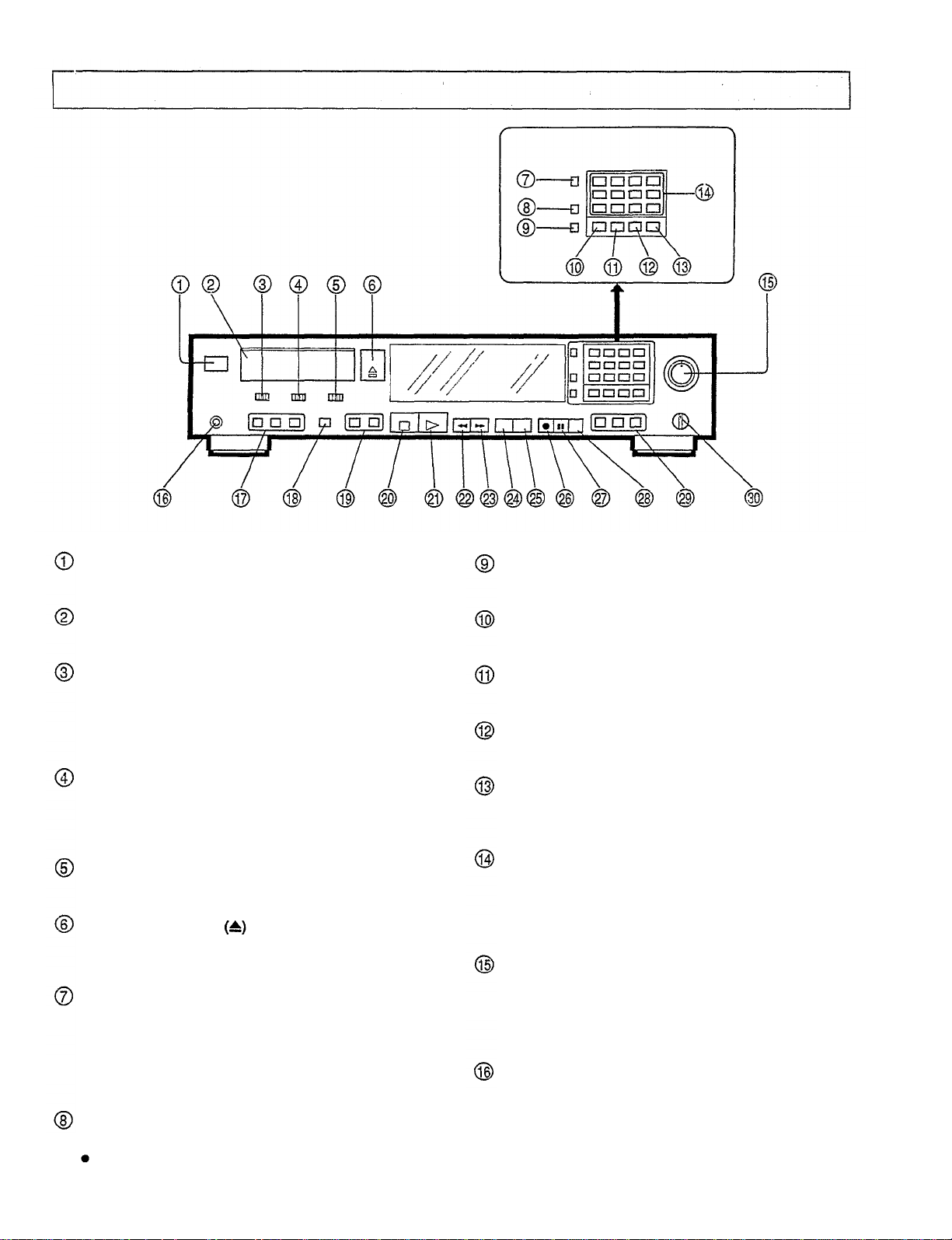
Front panel
NAMES OF CONTROLS
POWER switch
Turns the power on and off.
Cassette holder
Holds the digital audio tape.
INPUT selector
Set to DIGITAL to record from an audio source
connected to the DIGITAL INPUT terminals. Set to
ANALOG to record from an audio source connected to
the ANALOG INPUT terminals.
REC fs (Recording Sampling Frequency) selector
When recording is performed using the ANALOG
INPUT terminals, the sampling frequency can be
switched to 44.1 kHz or 48 kHz.
SKIP PLAY switch
Switches the skip play function.
OPEN/CLOSE button
Press to open the cassette holder, press again to close
it.
DISPLAY button
Selects either absolute time (ABS) or individual tune
playback time (PROG) or tape counter (COUNTER).
When tapes which contain "TOC" signals are used, the
total number of tunes and total playback time are
displayed.
REPEAT button
Press to continuously repeat playback.
PROGRAM button
Used for programming tunes.
CLEAR button
Press to clear the input digit or programmed tune No.
CALL button
Press to check the program contents.
ABS (Absolute) TIME button
Press to input the specified time for absolute time
search.
Digit buttons
Used to select desired tune numbers for program
playback or direct playback. These buttons are also
used to input the specified time for absolute time
search.
REC (Record) LEVEL control
Used to adjust the recording level when recording from
an audio source connected to the ANALOG INPUT
jacks. This control can adjust the left and right channels
independently.
PHONES jack
Connect stereo headphones to this jack,
COUNTER RESET button
Press to reset the tape counter (0000).
Only effective in counter display mode.
5
Page 6
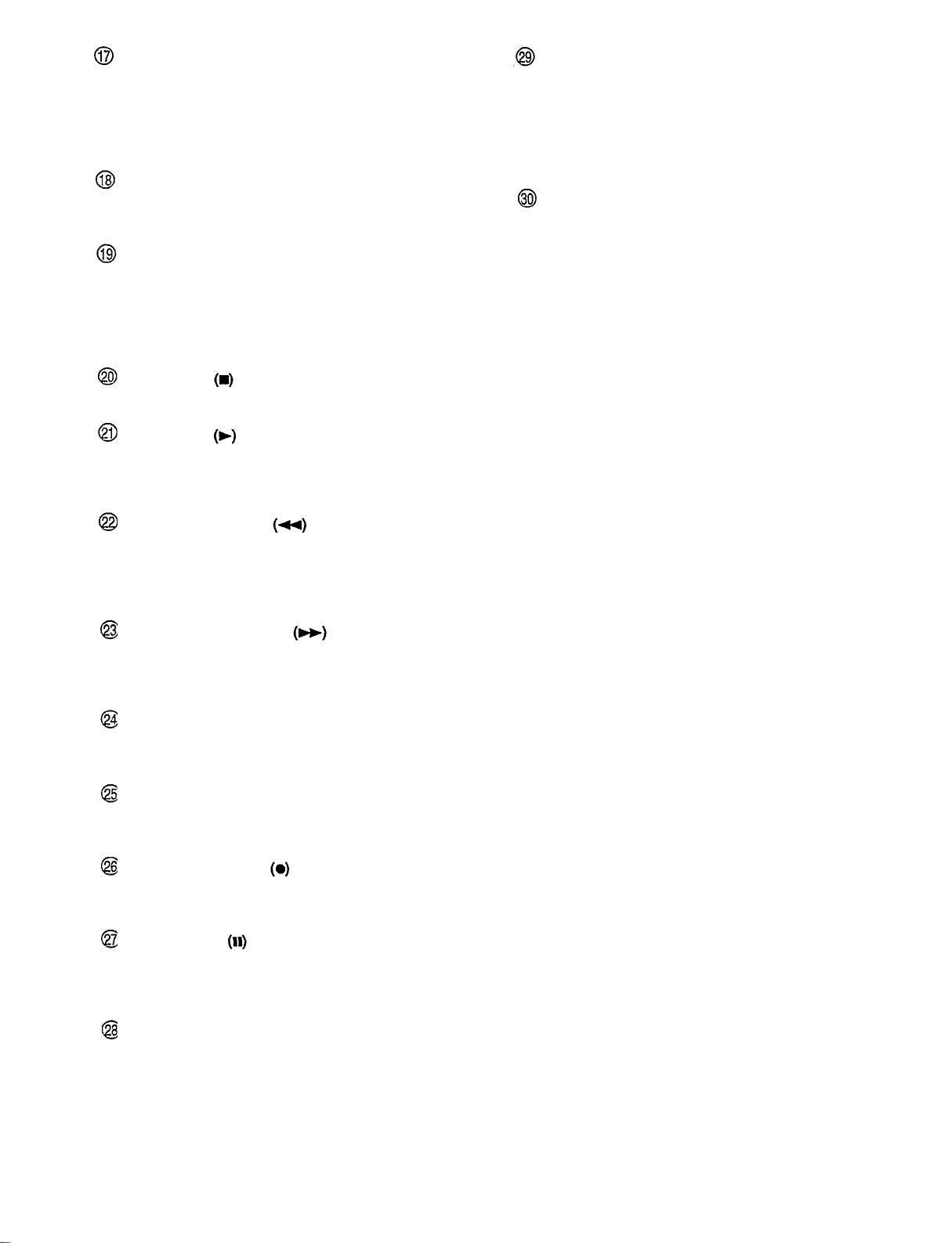
START ID buttons
AUTO WRITE: Press to automatically write the start ID
signals and their tune numbers during recording.
WRITE: Used to write the start ID signal manually
during recording or playback.
ERASE: Press to erase the start ID signal.
RENUMBER button
Used to renumber the tunes in sequence from the
beginning of the tape.
SKIP ID buttons
WRITE: Press to write the skip ID signal. When the
SKIP PLAY switch is set to ON, playback skips from the
point where this button was pressed to the beginning of
the next tune.
ERASE: Press to erase the skip ID signal.
STOP button
Press to stop the tape running.
PLAY button
Press to start playback. When the REC button is
pressed, pressing this button or the PAUSE button
initiates recording.
END ID buttons
WRITE: Press this button at the end of a recording.
The end ID signal is written to indicate that point.
ERASE: Press to erase the end ID signal.
SEARCH: Press to search for the end ID signal. The
tape rapidly goes to the end of a recording and
recording can be easily started from that point.
PHONES LEVEL control
Adjusts the volume of the headphones.
REW (Rewind) button
Press to rewind the tape.
When this button is pressed during playback, playback
starts from the beginning of the current tune. To play
the previous tune, press this button again (APSS).
FF (Fast forward) button
Press to fast forward the tape.
When this button is pressed during playback, playback
starts from the beginning of the next tune (APSS).
REVIEW button
Press to rewind the tape while listening to its contents at
approximately 3 times the normal speed.
CUE button
Press to fast forward the tape while listening to its
contents at approximately 3 times the normal speed.
REC (Record) button
Press to enter record stand-by mode. To start
recording, press the PLAY button or PAUSE button.
PAUSE button
Press to stop playback or recording temporarily. To
resume playback or recording, press the PLAY button
or this button again.
REC MUTE button
Press to create a blank section while recording. A
blank section continues as long as the button is
pressed.
6
Page 7
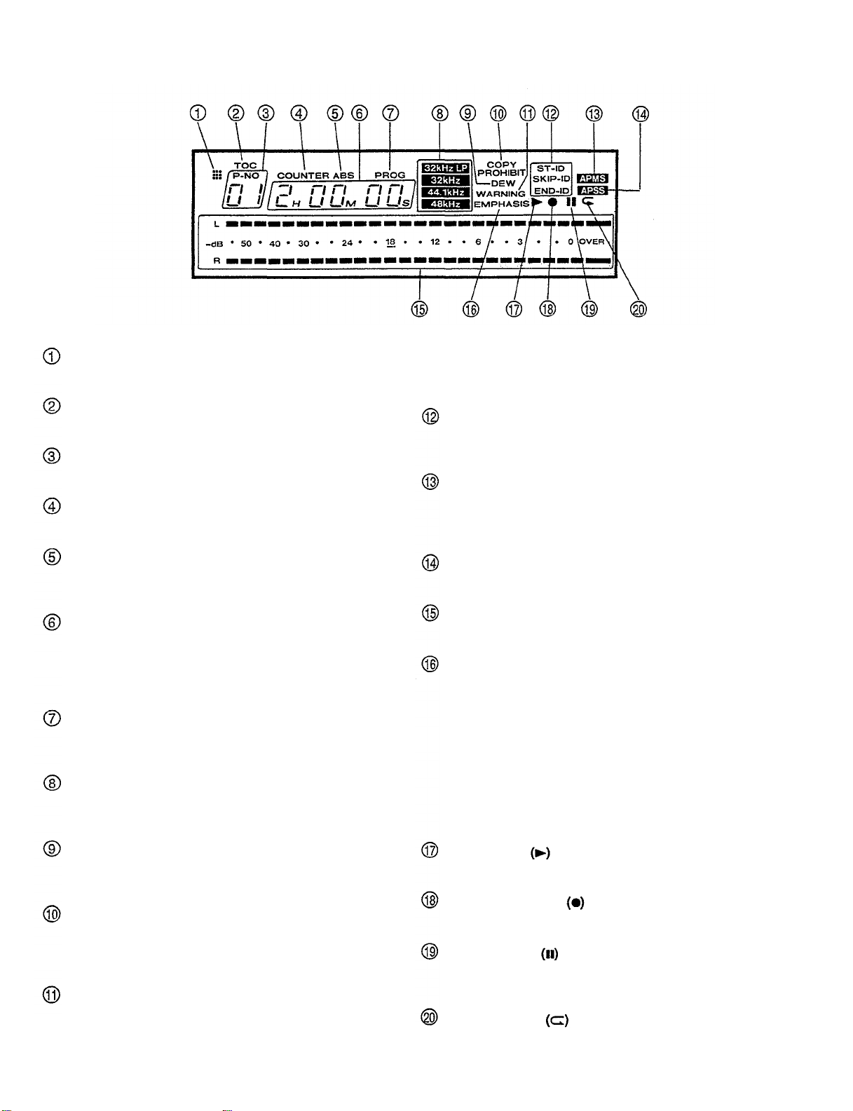
Display window
Remote control transmit indicator
Lights when the remote control transmitter is operated.
TOC (Table of Contents) indicator
Lights when a tape containing a TOC is played.
Tune number display
Indicates the tune number.
COUNTER indicator
Lights when the display is in counter mode.
ABS (Absolute time) indicator
Lights when the display shows ABS time (elapsed
playing time from the beginning of the tape).
Counter/ABS time/Tune playing time/Programmed
tune number display
Displays the tape counter reading, ABS time, tune
playing time (elapsed playing time from the beginning
of the current tune) or programmed tune number.
PROG indicator
Lights when the display shows the elapsed playing time
from the beginning of the current tune.
Sampling frequency indicators
Light according to the sampling frequency of the audio
signal.
If this occurs, use a commercially available digital audio
cleaning tape or have your Yamaha dealer clean the
head.
ST-ID/SKIP-ID/END-ID indicators
Light when the start ID, skip ID or end ID signal is
detected, or flashes when it is written or erased.
APMS (Automatic Programmable Music Selector)
indicator
Appears when programming or during program
playback.
APSS (Auto Program Search System) indicator
Appears when the beginning of a tune is searched for.
Peak level meter
Displays the recording level or playback level.
EMPHASIS indicator
Appears when tapes recorded with emphasis are
played, or when recording from a digital source on
which emphasis is applied. The emphasis function
reduces the noise of the high frequency revel by
boosting the high frequency level during recording
(Pre-emphasis function) and lowering it during
playback (De-emphasis function). This unit
incorporates only the de-emphasis circuit. You can
play or record emphasized signals but cannot newly
apply emphasis to signals.
DEW indicator
Appears when condensation occurs in this unit (drum,
head, etc.).
COPY PROHIBIT indicator
Appears when a recording cannot be performed with a
digital signal. In this case, record the source using the
ANALOG jacks.
WARNING indicator
If the head becomes excessively dirty, a signal read
error occurs during playback, and the sound cannot be
heard. At this time, the "WARNING" indicator appears.
Play indicator
Lights when the PLAY button is pressed.
Recording indicator
Lights when the REC button is pressed.
Pause indicator
Lights when the PAUSE button is pressed, or in record
stand-by mode.
Repeat indicator
Lights during repeat playback.
7
Page 8
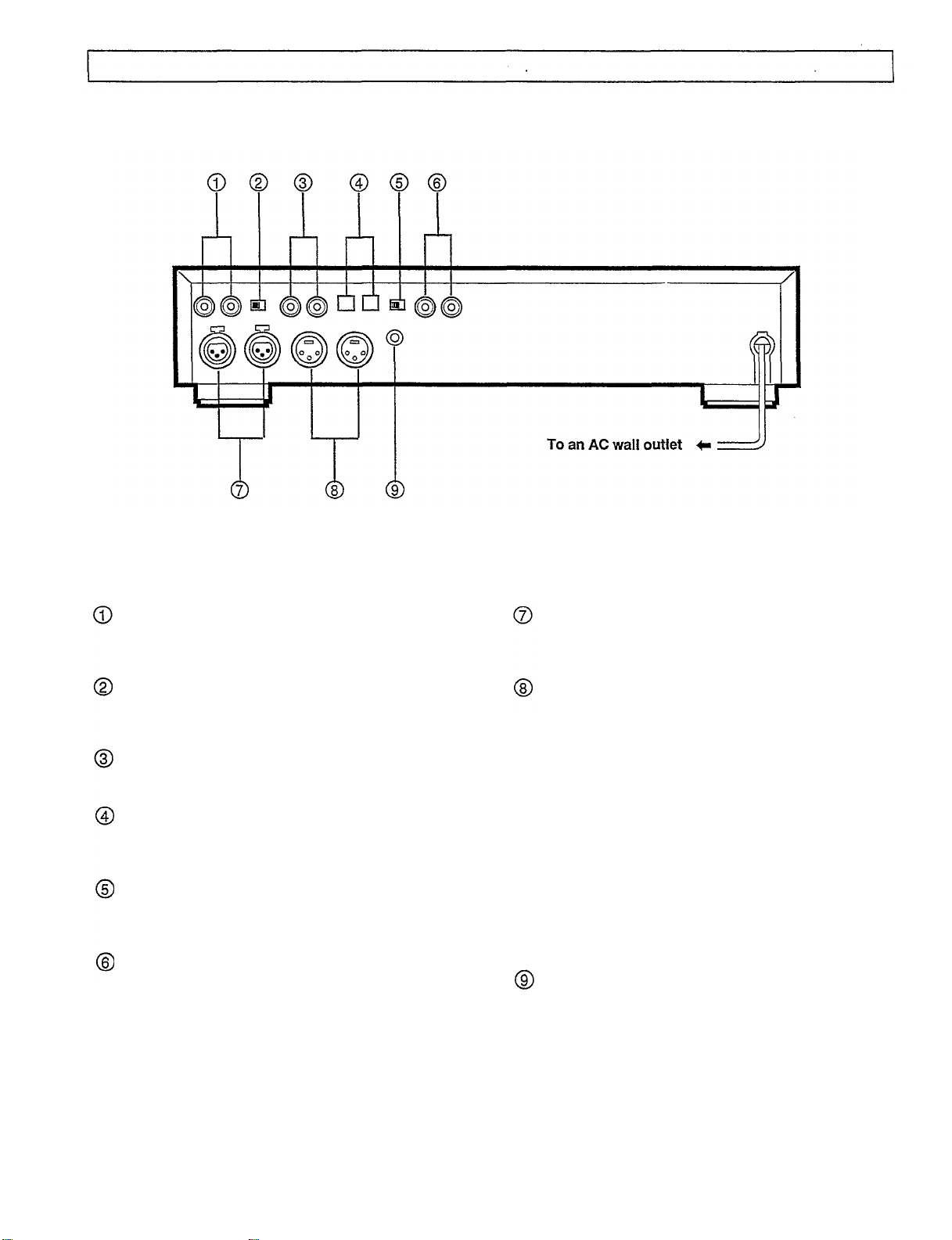
NAMES OF CONTROLS
Rear Panel
ANALOG INPUT jacks (unbalanced type pin-jacks)
When these jacks are used for recording, adjust the
input level with the REC LEVEL control.
ANALOG INPUT selector
Used to select the analog input jacks between
balanced type (XLR) and unbalanced type.
ANALOG OUTPUT jacks (unbalanced type pin-jacks)
Maximum output level is 2 V.
OPTICAL DIGITAL INPUT/OUTPUT jacks
These optical digital I/O jacks are based on EIAJ CP
340 specifications.
DIGITAL INPUT selector
Used to select the digital input jacks between OPTICAL
and COAXIAL.
COAXIAL DIGITAL INPUT/OUTPUT jacks
These coaxial digital I/O jacks are based on IEC 958
specifications.
ANALOG INPUT terminals (balanced type Cannonjacks)
The second pin is HOT.
ANALOG OUTPUT terminals (balanced type
Cannon-jacks)
Reference level is +4 dBm.
Pin assignment of the balanced type (XLR-3-31/XLR-
3-32) connectors
REMOTE jack
Connect to the plug of the supplied remote control
transmitter.
* Never connect a remote control unit other than the
supplied remote control transmitter.
8
Page 9
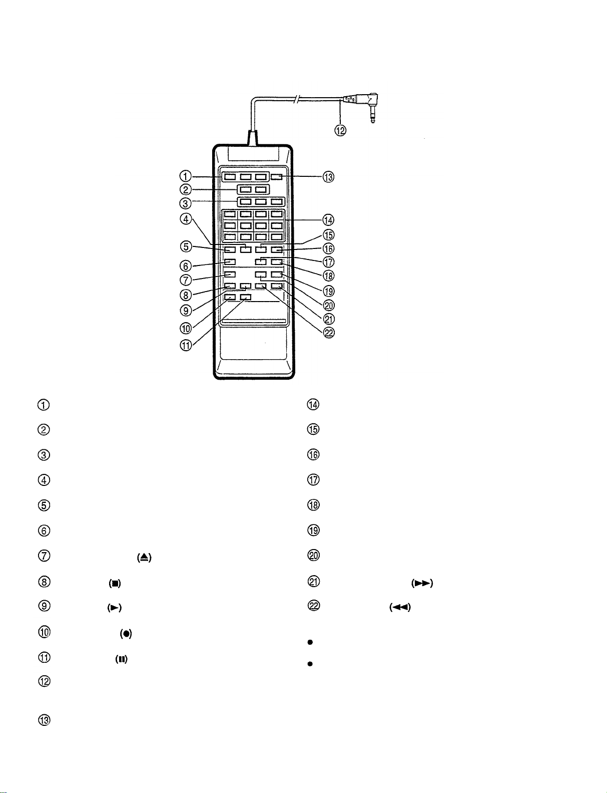
Wired remote control transmitter
Start ID buttons
Skip ID buttons
End ID buttons
Clear button
Program button
Repeat button
Open/close button
Stop button
Play button
Record button
Pause button
Remote control cable
Connect to the REMOTE jack on the rear panel.
Digit buttons
Call button
Absolute time button
Display button
Counter reset button
Cue button
Review button
Fast forward button
Rewind button
NOTES:
All buttons have the same functions as those on the
front panel.
The remote control transmitter does not require any
battery. Power is supplied from the REMOTE jack on
the rear panel.
Renumber button
9
Page 10
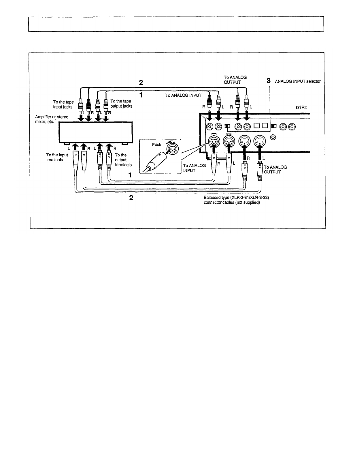
Connecting an analog audio component
CONNECTIONS
•
Be sure to disconnect the power cords of both
components from the AC outlet before connecting.
•
The same channels of this unit and the other
component should be connected properly; right to
right, and left to left.
1 Connect the ANALOG INPUT jacks (balanced type or
unbalanced type) of this unit to the analog output jacks
of the amplifier or stereo mixer, etc.
2 Connect the ANALOG OUTPUT jacks (balanced type or
unbalanced type) of this unit to the analog input jacks
of the amplifier or stereo mixer, etc.
3 Set the ANALOG INPUT selector. When using the
balanced type terminals, set this selector to the XLR
position. When using the unbalanced type jacks, set
this selector to the PIN position.
NOTE:
Make sure all connections are securely made. Loose
connections may cause intermittent sound or noise.
10
Page 11

Connecting to another digital audio tape deck, or an amplifier, etc. which has digital jacks
When this unit is connected to another DAT deck,
amplifier or other digital source, such as a CD player
with digital jacks, digital-to-digital recording will be
carried out.
Be sure to disconnect the power cords of both
components from the AC outlet before connecting.
When using the COAXIAL DIGITAL jacks
1 Connect the COAXIAL DIGITAL INPUT jack to the
coaxial digital output jack and the COAXIAL DIGITAL
OUTPUT jack to the coaxial digital input jack of another
DAT deck, or amplifier, etc. using the coaxial cables.
2 Set the DIGITAL INPUT selector to the COAXIAL
position.
When using the OPTICAL DIGITAL jacks
1 Connect the OPTICAL DIGITAL INPUT jack to the
optical digital output jack and the OPTICAL DIGITAL
OUTPUT jack to the optical digital input jack of another
DAT deck, or amplifier, etc. using the optical fiber
cables.
2 Set the DIGITAL INPUT selector to the OPTICAL
position.
NOTES:
When the POWER switch is turned on, the inside of the
OPTICAL OUTPUT jack illuminates red. This red light
(which is completely harmless) is used to send the
digital signal.
Do not fold or bend the optical fiber cable because it
damages easily.
11
Page 12

Connecting the remote control transmitter
By connecting the remote control cable to the REMOTE jack on the rear panel, this unit can be operated with the remote
control transmitter.
NOTES:
Do not strike or drop the remote control transmitter.
Also, do not get the remote control transmitter wet or
place it in a humid location.
Connecting headphones
Connecting the AC power cord
Do not connect this remote control transmitter to other
equipment.
Connect only the supplied remote control transmitter to
the REMOTE jack.
For best results, use 8-ohm to 32-ohm headphones with a
standard stereo headphone plug 1/4" (6.3 mm).
The headphone volume can be adjusted with the PHONES
LEVEL control.
After connecting all equipment, connect the AC power cord
plug to an AC wall outlet.
12
Page 13

DAT (Digital Audio Tape)
DAT cassettes
A DAT cassette measures 2-7/8" x 7/16" x 2-1/8" (73 mm x
10.5 mm x 54 mm), nearly half the size of analog audio
cassettes. Furthermore, the case is constructed to prevent
the tape from being scratched or soiled.
DAT recording scheme
In the DAT system, the head is rotated at high speed and
mounted at an angle with respect to the direction of tape
travel.
The PCM (audio signal) area is recorded with the digital
signal which has been converted from the audio signal.
(PCM=Pulse Code Modulation). The subcode areas are
recorded with information such as the tune number,
individual tune elapsed time and absolute time. The
subcode areas enable accurate tune searching since the
signals in the subcode areas are read while the tape is
moving.
Sampling frequencies
There are 3 sampling frequencies used when converting
analog audio signals to digital signals: 48 kHz, 44.1 kHz
and 32 kHz.
48 kHz: Used for commercially available DAT music tapes
or standard recorded DAT tapes.
44.1 kHz: Used for commercially available DAT music tapes
and CDs.
32 kHz: Used for satellite broadcasts.
At 32 kHz, this DAT deck can not record analog signals.
13
Page 14

Preventing accidental erasure
To prevent accidental erasure, slide the tab to the left to
open the hole. The tape cannot be recorded even if the
REC button is pressed. See Fig. A.
To allow recording on the tape again, slide the tab to
the right to close the hole. See Fig. B.
Handling digital audio tapes
Digital audio tapes are precisely constructed to record
and play back highly accurate data. Never open the
cassette lid and touch the tape. Touching the tape may
damaged it.
Do not use scratched, dirty or wrinkled tapes. Use of
such tapes may cause sound dropouts or damage the
head.
Storing digital audio tapes
Always keep tapes that are not in use in their cases.
Avoid storing tapes in direct sunlight, near heat
generating equipment or in humid locations.
Avoid storing tapes in dusty locations.
Do not store near strong magnetic fields (e.g. near
electric clocks, toys using magnets, etc.). Magnetic
fields will damage recordings.
Do not drop or subject the tape to strong vibrations.
Rewind the tape after use. If there is any slack in the
tape, rewind again.
Serial Copy Management System (SCMS)
Most digital sources contain a copy prohibit code. This
unit utilizes the serial copy management system that
permits digital-to-digital recording for at least one
generation.
Even when a tape which has been recorded from analog
sources is dubbed, this system regards the source as a
digital source containing the copy prohibit code since the
dubbing was performed through the A/D converter, and
permits digital-to-digital recording only for one generation.
14
Page 15

Loading a cassette
LOADING AND UNLOADING CASSETTES
1 Turn the POWER switch ON.
2 Press the OPEN/CLOSE button
cassette holder.
"OPEN" flashes on the display.
to open the
3 Place a DAT cassette in the cassette holder.
Be sure the window of the cassette faces you and the
slide tab faces you on the right side.
4 Press the OPEN/CLOSE button
the cassette holder.
Unloading the cassette
1 Press the OPEN/CLOSE button
cassette holder.
2 Remove the cassette from the cassette holder.
3 Press the OPEN/CLOSE button
the cassette holder.
NOTES:
The cassette holder will not close completely if the tape
is inserted improperly. In this case, press the OPEN/
CLOSE button
insert again.
If the cassette holder does not close completely, it will
automatically open after about 10 seconds even if the
OPEN/CLOSE button
Do not attempt to open or close the cassette holder by
hand. Doing so will damage it.
to open the cassette holder and
is not pressed.
again to close
to open the
again to close
15
Page 16

RECORDING
Introduction to DAT recording
Unlike ordinary audio cassette tapes, various control codes
called subcodes can be written on the DAT cassette tape
separately from the audio signal. The subcodes are written
for a variety of convenient playback and tape editing
functions. You can write three types of subcodes; start ID,
end ID and skip ID.
Start ID: Indicates the beginning of each tune and is used
for programming and searching for tunes.
End ID: Indicates the end of the recording.
Skip ID: Indicates the beginning of a section to be
skipped.
In addition, absolute time is automatically written after the
recording is completed.
Before making an important recording, it is
recommended that you make a trial recording to ensure
that the desired audio is being recorded properly.
Recording from the digital input jacks (coaxial or optical jack)
This procedure is recommended when recording from another DAT deck
or other digital audio source.
1 Turn the POWER switch ON.
Whenever the POWER switch is turned ON, the START
ID AUTO WRITE button is set to on and the button
lights up. The tune numbers will be written
automatically during recording. If the tune numbers are
not necessary, press the START ID AUTO WRITE button
so that the light of the button goes off.
2 Set the INPUT selector to the DIGITAL position.
3 Set the DIGITAL INPUT selector on the rear panel
according to the jacks to be used.
Coaxial jacks: Set to the COAXIAL position.
Optical jacks: Set to the OPTICAL position.
4 Load a DAT cassette in the cassette holder.
5 Press the REC button
The unit enters record stand-by mode. When recording
from the beginning of the tape, a sound muted section
of about 7 seconds is automatically recorded before the
deck enters record stand-by mode.
6 Set the source to be recorded to play mode and
Dress the PLAY button to start recording.
When the START ID AUTO WRITE button is set to on
and the unit encounters a sound muted section of more
than 2 seconds, a start ID is written and the tune is
numbered automatically.
16
7 When the recording is completed, press the END ID
WRITE button.
After the end ID signal is written, the tape stops
automatically.
If the end ID signal is written, it is easy to continue a
recording from the end of a previous recording. See
page 20.
NOTES:
When digital sources are recorded from a DAT deck
which can send category code "DAT and the start ID
and skip ID signals to digital outputs, make sure the
START ID AUTO WRITE button is turned on (lit). The
unit records start ID and skip ID signals, which are
contained in the source, as they are.
If the power of the source to be recorded is turned off,
the unit enters record stand-by mode and the tape
running stops. In this state, turning on the power of the
source to be recorded resumes recording starting from
the next tune number.
When recording through the digital input jacks, no
signal is output to the digital output jacks.
Be sure to set the INPUT selector and DIGITAL INPUT
selector before recording. If they are switched during
recording, the unit enters pause mode.
The sampling frequency is automatically switched
according to the source being recorded.
When recording from the digital input jacks, there is no
need to adjust the recording level.
Page 17

Recording from the analog input jacks
This procedure is recommended when making a recording
from a mixing console, analog tape deck, tuner,
phonograph or other similar external audio source.
1 Turn the POWER switch ON.
2 Set the START ID AUTO WRITE button.
If the source to be recorded does not contain a sound
muted section
press the START ID AUTO WRITE button so that the
light of the button goes off.
3 Set the INPUT selector to the ANALOG position.
4 Set the REC fs selector.
5 Set the ANALOG INPUT selector on the rear panel
according to the jacks to be used.
Unbalanced pin jacks: Set to the PIN position.
Balanced pin jacks: Set to the XLR position.
6 Load a DAT cassette.
7 Press the REC button
The unit enters record stand-by mode. When recording
from the beginning of the tape, a sound muted section
of about 7 seconds is automatically recorded and the
unit enters record stand-by mode.
of
about 2 seconds between tunes,
When recording from these sources, the tune numbers may
not be written properly with the Start ID Auto Write function.
In this case, you can manually write start ID signals during
recording or after recording. See page 19.
8 Play the source to be recorded and adjust the
recording level with the REC LEVEL control. See
below.
9 Press the PLAY button to start recording.
10 When recording is completed, press the END ID
WRITE button.
After the end ID signal is written, the tape stops
automatically.
If the end ID signal is written, it is easy to continue a
recording from the end of a previous recording. See
page 20.
NOTE:
Be sure to set the INPUT, ANALOG INPUT and REC fs
selectors before recording. If the INPUT or REC fs selector
is switched during recording, the unit enters pause mode.
If the ANALOG INPUT selector is switched, a several-
second blank section is recorded.
To adjust the recording level when recording
from the analog input jacks
As a guide, adjust the recording level so that the peak level
meter is between"-18 dB" and "0". Be sure the peak levels
do not reach "OVER". If the peak levels exceed "0", "OVER"
lights and distorted sound may result.
If the recording levels for the left and right channels are
different, adjust the left and right channels separately
(See the figure.)
17
Page 18

To stop recording temporarily
1 Press the PAUSE button
Recording stops temporarily.
2 Press the PLAY button or PAUSE button
again to resume recording.
When the START ID AUTO WRITE button is ON (lit), the
start ID signal is written at the point where recording
resumes.
NOTE:
To protect the tape and the head, the head will separate
from the tape after about 5 minutes have passed in
recording pause mode.
Blank sections and sound muted sections
With conventional analog audio tapes, the sections on
which no recording has ever been made (blank section
created with fast-forwarding, etc.) and the sections on
which a recording has been made but the sound is muted
(sound muted section created with the record muting
function) are treated the same, and they are used to search
for tunes, since no sound can be heard from these sections.
Conversely, the DAT deck distinguishes between blank
sections and sound muted sections. If blank sections
remain on the tape, search operation using the APSS
function may take quite a long time and search operation
using absolute time may not be carried out properly.
Therefore, when recording, be sure that no blank sections
are left on the tape.
In addition, since no-sound sections between tunes must be
recorded on analog audio tapes for tune search operation,
recording no-sound sections (sound muted sections)
between tunes is recommended considering dubbing from
DAT cassettes to analog audio tapes.
To insert silence between tunes, press the REC MUTE
button during recording. A sound muted section will be
created as long as the button is kept pressed. It is
recommended to create a sound muted section of
about 4 seconds for dubbing onto an analog audio tape
later on. Do not create a blank section by advancing
the tape with the FF button or PLAY button
To start recording from the middle of the tape, use the
end search function (page 20) to locate the end of the
previous recording. This will avoid leaving a blank
section.
18
Page 19

START ID SIGNALS AND TUNE NUMBERS
The actual number of a recorded tune on a tape and the
tune number displayed on the unit may not be the same,
even if the tune numbers are written automatically with the
START ID AUTO WRITE function. This may occur due to the
contents of the recorded tune.
The tune numbers may not be recorded properly when
recording from sources that contain the following:
Conversations with breaks in them.
Low overall recording level.
Short intervals (i. e., 2 seconds or less) between tunes.
Long quiet pianissimo passages.
Noise or hum between tunes.
If the tune numbers are not written properly, it may be
necessary to add or erase the tune numbers.
When recording is performed from sources without silence
between tunes, it is recommended to write the tune
numbers manually during recording or after recording.
To write tune numbers manually during
recording
Press the START ID WRITE button (the button lights) at
the beginning of each tune.
Every time the START ID WRITE button is pressed, the start
ID signal is written and the tune number is switched to next
number. While the start ID signal is written, the ST-ID
indicator flashes.
Manually writing the tune numbers is possible
regardless of the setting of the START ID AUTO WRITE
button.
Up to 99 tune numbers can be written. If a tape which
contains more than 99 tunes is played, the tune number
is not displayed after the 100th tune.
To write start ID signals manually during
playback
A start ID signal indicates the beginning of a tune. If this
signal and corresponding tune number are not written, tune
selection by APSS, APMS and direct selection is
impossible.
If start ID signals and tune numbers are not written properly
on a tape, insert start ID signals according to the following
procedure, and then renumber them (page 20).
1 During playback, press the START ID WRITE button
(the button starts flashing) at the point where the
start ID signal is to be inserted.
The tape is played back for 3 seconds and then
rewound to a point 2 seconds before the START ID
WRITE button was pressed. Playback starts from this
point for 5 seconds and repeats 10 times (Test
playback). Since the ST-ID indicator lights when the
tape encounters the start-ID signal, the placement of
the start ID signal can be verified. Check the position
of the start ID signal while listening to the test playback.
2 If the start ID signal is not correctly inserted at the
beginning of the tune, move it backward or forward
with the REW or FF button.
Each time the REW button
signal moves backward 0.3 seconds. Each time the FF
button is pressed, the start ID signal moves
forward 0.3 seconds.
3 When the start ID signal is correctly inserted, press
the START ID WRITE button again during test
playback.
The button lights and the tape is rewound to the
beginning of the tune, and the start ID signal is written.
(While writing, the ST-ID indicator flashes.) Playback
resumes after the start ID) signal is written.
is Dressed, the start ID
19
Page 20

Notes on writing start ID signals
If a start ID signal is written on a point where a skip ID
signal has been written, the skip ID signal is erased.
The interval between start ID signals (playing time of a
tune) should be 9 seconds or more. This 9-second
interval is necessary to ensure proper operation of the
APSS function, APMS function and renumbering tunes.
To erase start ID signals
If a start ID signal is written on a undesirable point, you can
erase it during playback. Be sure to renumber the tunes
after erasing a start ID signal.
Press the START ID ERASE button (the button flashes)
when the ST-ID indicator appears on the display.
The tape rewinds to the beginning of the tune being played
and the start ID signal is erased. While erasing, the ST-ID
indicator flashes. Playback resumes after the start ID
signal is erased.
If a tune number is also written with the start ID, both
signals will be erased at the same time.
To renumber tune numbers
When start ID signals are inserted or erased, tune numbers
are displaced. Renumber the tune numbers following this
procedure.
END ID SIGNALS
An end ID signal indicates the end of a recording. The tape
does not advance beyond the point where this signal is
written. Therefore, it is easy to continue a recording from
Press the RENUMBER button in stop mode.
The tape is rewound to the beginning of the tape, and the
tune numbers are automatically renumbered at high speed.
Whenever the unit encounters a start ID signal, the proper
tune number is written starting from P-NO 1.
When renumbering is completed at the end of the tape,
the tape automatically rewinds to the beginning.
the end of a previous recording. Also, this will avoid making
a blank section between recordings.
To write an end ID signal
During recording, press the END ID WRITE button.
A sound muted section is automatically inserted and the
end ID signal is written. While the end ID signal is being
written, the END-ID indicator flashes and then the tape
automatically stops.
When the unit encounters an end ID during playback,
fast-forwarding or cueing, the tune number changes to
"EE", and the tape stops automatically.
Do not write an end ID signal if the interval between
start ID signals is shorter than 9 seconds. APSS and
renumbering functions may not be carried out properly.
20
Page 21

To continue a recording from the end of a
previous recording
1 Press the END ID SEARCH button in stop mode or
during playback.
The button starts flashing. The tape is rewound to the
beginning and then fast-forwarded to the point where
the end ID signal is written (End search function). The
light of the button goes off when the tape stops.
2 Start recording from the point where the tape stops.
Tune numbers and absolute time will be continued from
the previously recorded contents.
The end ID signal of the previous recording is
automatically erased.
To erase the end ID signal
An end ID signal is automatically erased when successive
recording is performed using the end search function. To
erase an end ID signal without successive recording,
perform the following procedure.
When the tape stops after end search operation, press
the END ID ERASE button.
The button starts flashing. When the end ID signal is
erased, the tape stops. (While erasing the end ID signal,
the tape is advanced for a few seconds and the END-ID
indicator flashes.)
To erase the recorded contents
When a recording is made over a previous recording, the
previous recording is automatically erased. To erase the
recorded contents without making a new recording, perform
the following procedure.
1 Set the INPUT selector to the ANALOG position.
2 Load the tape in the cassette holder.
3 Turn the REC LEVEL control fully counterclockwise
to 0 (MIN).
4 Press the REC button
5 Press the PLAY button
The previously recorded contents will be erased.
21
Page 22

Normal playback
PLAYBACK
1 Load the tape into the cassette holder.
2 Press the PLAY button
To stop playback
1 Press the STOP button
2 To start playback again, press the PLAY button
To stop playback temporarily
1 Press the PAUSE button.
2 To resume playback, press the PLAY button
PAUSE
To protect the tape, the pause mode automatically
cancels after 5 minutes and the unit enters stop mode.
button again.
or
22
To fast-forward or rewind the tape
1 To fast-forward the tape, press the STOP button
then the FF button
To rewind the tape, press the STOP button
the REW button
2 Press the STOP button to stop the tape running.
then
Page 23

APSS (Auto Program Search System)
APSS allows you to locate the beginning of any tune during
playback. Simply press the REW or FF
move backward or forward.
NOTES:
For tapes with a start ID signal interval shorter than 9
seconds, APSS may not function properly (page 20).
if a tune is not played according to the tune number
selected with APSS, the start ID signal and tune number
have not been correctly written. See page 19.
Press the FF button to go to the beginning of the
next tune. Press the REW button to return to the
beginning of the current tune.
Each press of the FF button skips to the beginning of
the subsequent tunes. Each press of the REW button
skips to the beginning of the previous tunes.
The tape can be caused at the beginning of the desired
tune by pressing the PAUSE button after pressing
theFF or REW button. The desired tune can
<Examples> then be played by pressing the PLAY button
To go to tune 4 while tune 3 is playing
Press the FF button
tune number indicator changes from 3 to a flashing 4 and
the tape is fast-forwarded to the beginning of tune 4.
Playback starts from the beginning of tune 4.
once while tune 3 is playing. The
button to
To replay from the beginning of tune 4 while tune 4 is
playing
Press the REW button
The tune number indicator changes to a flashing 4 and the
tape is rewound to the beginning of tune 4. Playback starts
again from the beginning of tune 4.
To skip to tune 8 while tune 5 is playing
Press the FF button
The tune number indicator changes from 5 to a flashing 8
and the tape is fast-forwarded to the beginning of tune 8.
Playback starts from the beginning of tune 8.
To skip to tune 6 while tune 10 is playing
Press the REW button
playing. The tune number indicator changes from 10 to a
flashing 6 and the tape is rewound to the beginning of tune
6. Playback starts from the beginning of tune 6.
once while tune 4 is playing.
three times while tune 5 is playing
five times while program 10 is
23
Page 24

To program desired tunes (APMS=Automatic Programmable Music Selector)
You can program desired tunes in any desired order.
If the tunes are not numbered properly, the desired tunes may not be programmed, or program playback may stop
suddenly.
1 Load the tape.
2 Press the PROGRAM button.
The APMS indicator lights.
3 Using the digit buttons (1-0, +10, +20), enter the
desired tune numbers in the desired order.
Example:
To select tune 12:
Press "+10" and "2".
To select tune 20:
Press "+20" and "0".
To select tune 54:
Press "+20" twice, "+10" and "4".
The display shows the program number (playback
order) and the programmed tune number.
4 Press the PLAY button
The programmed tunes are played in the programmed
order.
To skip to the beginning of a tune in the program:
Press the FF or REW
beginning of previous/subsequent programmed tunes.
To check the program contents
In stop mode, press the CALL button.
The programmed tunes are displayed in programmed
order.
When the CALL button is pressed during program
playback, the next programmed tune number to be
played is displayed for about one second.
button to skip to the
24
To erase a programmed tune
Press the STOP button then the CLEAR button.
Each time the CLEAR button is pressed, one programmed
tune will be erased beginning with the last programmed
tune.
To clear the whole program
Press the PROGRAM button in stop mode. Also, pressing
the OPEN/CLOSE button or turning off the power clears the
whole program.
Page 25

Direct selection
Any tune can be directly selected and played back by
specifying the tune number.
In stop mode or play mode, enter the desired tune
number using the digit buttons (0-1, +10, +20).
Example:
To select tune 12:
Press "+10" and "2".
To select tune 20:
Press "+20" and "0".
To select tune 54:
Press "+20" twice, "+10" and "4".
The beginning of the specified tune will be searched for and
played automatically.
The direct selection function can be used to cue up to
the beginning of a tune. Enter a tune number and
press the PAUSE button
searched for and the unit enters pause mode. To start
playback, press the PLAY button
If a tune number which does not exist on the tape is
specified, the tape fast-forwards until the end.
Direct selection cannot be carried out on tapes which
do not contain tune numbers, or have their tunes
numbered incorrectly.
Direct selection cannot be used for programmed tunes
in APMS.
The specified tune is
Absolute time search
Playback can be started from any point when the absolute
time (from the beginning of the tape to the point where you
want to start playback) is specified.
1 Press the ABS TIME button in stop mode or
playback mode.
2 Enter the desired absolute time using the digit
buttons (0-1).
For example, when searching for "one hour, 25 minutes
and 32 seconds", press "1", "2", "5", "3" and "2".
3 Press the PLAY button
Playback starts from the specified ABS time.
When a time longer than the recording time on the tape
is specified, the tape will stop at the end.
During playback, the absolute time must be entered
within 4 seconds after pressing the ABS TIME button.
Otherwise, the function will be canceled.
25
Page 26

Cue and review
The CUE and REVIEW buttons allow you to quickly move to
a desired location on the tape while listening to the tunes at
3 times the speed of normal playback.
In stop mode:
1 Press the CUE button to move forward or the
REVIEW button to move backward.
2 Press the PLAY button
position is reached.
During playback:
1 Press and hold the CUE button to move forward or
the REVIEW button to move backward.
2 Playback will resume when the CUE or REVIEW
button is released.
When the end of the tape is reached, the tape stops
automatically.
NOTE:
The CUE and REVIEW buttons do not function for
programmed tunes in APMS.
when the desired
Repeat playback
Repeat playback allows you to continuously repeat an entire
tape or a program in APMS. To repeat a program, program
the tunes beforehand (page 24).
1 Press the REPEAT button.
The
indicator lights.
The entire tape or program will be played repeatedly.
To return to normal playback, press the REPEAT button
again.
Repeat playback will stop automatically after playback
is repeated 24 times.
2 Press the PLAY button
26
Page 27

To skip undesirable sections-using the skip ID
When the unit encounters a skip ID signal, the tape fastforwards to the beginning of the next tune.
To write the skip ID signal
During playback, press the SKIP ID WRITE button at the
beginning of the section to be skipped.
The button lights. Playback stops temporarily and the skip
ID signal is written. (While writing, the SKIP-ID indicator
flashes.)
Skip playback
Set the SKIP PLAY button to the ON position.
When a skip ID signal is detected during playback, the tape
fast-forwards to the beginning of the next tune and
playback resumes.
When you want to play a tape containing a skip ID
signal without the skip play function, set the SKIP PLAY
button to the OFF position. The tape will be played
normally, but the skip ID signal is not erased.
To erase the skip ID signal
1 Set the SKIP PLAY button to the OFF position.
2 Play the tune which contains the skip ID to be
erased, and press the SKIP ID ERASE button when
the SKIP ID indicator lights.
The tape is rewound to the position where the skip ID
was written. The SKIP ID indicator flashes and the skip
ID is erased. Playback resumes after the skip ID is
erased.
27
Page 28

To display elapsed time and the tape counter
Each time the DISPLAY button is pressed during playback,
the display changes to 1, 2, or 3, in that order.
1 The PROG indicator lights and the elapsed playback
time from the beginning of the current tune is
displayed.
When a tune which does not contain a start ID signal is
played,"-- M -- S" is displayed.
The absolute time is displayed during APSS mode.
In fast-forward, rewind, cue or review mode,"-- M --S" is
displayed.
2 The COUNTER indicator lights and the tape counter
reading is displayed.
To reset the counter reading, press the COUNTER
RESET button. The display shows "0000". In any other
display mode, the COUNTER RESET button does not
function.
3 The ABS indicator lights and the total elapsed time
(absolute time) from the beginning of the tape is
displayed.
For tapes on which the absolute time is not recorded, "-M --S" is displayed.
NOTES:
When a section which does not contain both a start ID
signal and a tune number is played, the tune number is
not displayed.
28
Page 29

TROUBLESHOOTING
If this unit functions abnormally during operation, first check the following items. If the unit continues to function abnormally, or
if an abnormality other than those listed below appears, turn off the deck's power and disconnect the AC plug, then consult
your Yamaha dealer or servicing personnel.
PROBLEM
Power does not turn on.
The cassette holder does not close after a tape is
loaded.
This unit does not operate.
No playback sound from both channels.
No playback sound from one channel.
The absolute time is incorrectly displayed.
The actual number of recorded tunes and the tune
numbers do not match, (e.g. There are 6 recorded
tunes but tune numbers are 1, 2, 3, 4 and 5 only.)
A tune selected with APSS or APMS is not the desired
tune.
The tape stops during APMS operation.
CHECK
Is the AC power cord plugged in?
Is the tape loaded properly?
Is a DAT cassette used?
Is there a tape loaded?
Are there any foreign objects in the cassette holder?
Is there dew on the head or tape?
Is this unit connected properly to an amplifier?
Is a cable loose or disconnected?
Are the program numbers written in the correct order?
This can happen with certain types of recorded material
(caused by noise between tunes, short interval between
tunes, dropouts, etc.). See page 19.
Do the actual number of recorded tunes and the tune
numbers match? See page 19.
Are all the APMS tune numbers valid?
Are the tune numbers renumbered?
The sound from the digital input cannot be recorded.
The recording level cannot be adjusted when recording
from the digital input.
Clicking sounds are heard from the tape deck when a
button is pressed.
Is the INPUT selector set to DIGITAL?
Is the coaxial cable or optical fiber cable connected
properly?
Is the DIGITAL INPUT selector on the rear panel set
properly?
Is the optical fiber cable cut or broken?
There is no need to adjust the recording level when
recording from the digital input.
These sounds are heard when the tape or head protection
function is operating.
These sounds may also be heard when a blank section on
the tape is reached during fast-forwarding or rewind.
(These sounds are normal.)
29
Page 30

SPECIFICATIONS
DAT system Rotary head type digital audio tape recorder
Loading system
Recording system
Recording sampling frequency
Digital
Analog
Quantization system
Tape speed
Fast winding time
Overall frequency response
fs=48 kHz
fs=44.1 kHz
THD + Noise
Dynamic range
Separation
Digital input
Coaxial
Optical
Digital output
Coaxial
Optical
Analog input
Balance
Unbalance
Analog output
Balance
Unbalance
Headphone output
Power consumption
Serial Copy Management System
48 kHz, 44.1 kHz, 32 kHz/2-channeI
45 sec. maximum for 120-minute tape
Ref. level +4 dB/10 kohms (XLR 3-31)
2 Vrms maximum (RCA pin jack)
Horizontal front loading
48 kHz, 44.1 kHz/2-channeI
16 bit linear conversion
8.15
mm /sec.
2 Hz to 22 kHz,
2
Hz to 20 kHz,
0.003% at 1 kHz
0.2 Vp-p/75 ohms (IEC 958)
0.5 Vp-p/75 ohms (IEC 958)
0.3 Vrms minimum
for full scale (RCA pin jack)
Ref. level +4 dBm/
Full scale +22 dBm (XLR 3-32)
75 mW/32 ohms maximum
(1/4" phone jack)
±0.5
dB
±0.5
dB
92 dB
1
96 dB at
(EIAJ CP-340)
(EIAJ CP-340)
kHz
28
W
Power supplies
U.S.A. model
Europe model
Dimensions (W x H x D)
(18-7/8" x 3-7/16" x 12-15/16")
Weight
Accessories
Remote control transmitter
* Specifications subject to change without notice.
120
230
480
x
88 x 329 mm
6 kg
(13
V,
V,
IDS.
60 Hz
50
Hz
4 oz.)
1
30
Page 31

This product complies with the radio frequency interference
requirements of the Council Directive 82/499/ECC and /or
87/308/EEC.
Page 32

YAMAHA
SERVICE
This product is supported by Yamaha's worldwide network of
factory trained and qualified dealer service personnel.
In the event of a problem, contact your nearest Yamaha
dealer.
YAMAHA CORPORATION
 Loading...