

Yamaha DME32 User Manual

Version 1.5
DIGITAL MIXING ENGINE
Owner’s Manual Supplement
Contents
Introduction . . . . . . . . . . . . . . . . . . . . . . . . . . . . . . . . . . . . . . . . . . . . . . . . . . . . . . . . . . 2
32x32 & 32x16 Matrix Mixer Components . . . . . . . . . . . . . . . . . . . . . . . . . . . . . . . . . 2
Stereo PEQ & GEQ Components . . . . . . . . . . . . . . . . . . . . . . . . . . . . . . . . . . . . . . . . . 4
Parameter Value Copy . . . . . . . . . . . . . . . . . . . . . . . . . . . . . . . . . . . . . . . . . . . . . . . . . . 7
Recall Safe . . . . . . . . . . . . . . . . . . . . . . . . . . . . . . . . . . . . . . . . . . . . . . . . . . . . . . . . . . . . 8
Keyboard & Scrolling Mouse Control . . . . . . . . . . . . . . . . . . . . . . . . . . . . . . . . . . . . . 9
Program Library . . . . . . . . . . . . . . . . . . . . . . . . . . . . . . . . . . . . . . . . . . . . . . . . . . . . . 10
Fade Time . . . . . . . . . . . . . . . . . . . . . . . . . . . . . . . . . . . . . . . . . . . . . . . . . . . . . . . . . . 13
Improved Node Labelling . . . . . . . . . . . . . . . . . . . . . . . . . . . . . . . . . . . . . . . . . . . . . 15
Improved DME Manager Uninstall . . . . . . . . . . . . . . . . . . . . . . . . . . . . . . . . . . . . . 15
Support for Legacy Configurations . . . . . . . . . . . . . . . . . . . . . . . . . . . . . . . . . . . . . . 15
Editing Multiple Parameters Simultaneously . . . . . . . . . . . . . . . . . . . . . . . . . . . . . 16
Improved Parameter Resolution . . . . . . . . . . . . . . . . . . . . . . . . . . . . . . . . . . . . . . . . 16
Support for Windows NT 4.0, 2000 & Me . . . . . . . . . . . . . . . . . . . . . . . . . . . . . . . . 16
Software Version Mismatch Warning . . . . . . . . . . . . . . . . . . . . . . . . . . . . . . . . . . . 16

2
Introduction
This document describes the new features of DME32 Version 1.5 and should be used in
conjunction with the original DME32 Owner’s Manual .
32x32 & 32x16 Matrix Mixer Components
The new 32x32 and 32x16 Matrix Mixer components, shown below, allow the creation
of even larger matrix mixing systems. Note that since these components are processor
intensive, only one of these components can be used with a single DME32 at any one
time.
Each Matrix Mixer control window features an IN section, with various input channel
controls, and an OUT section, with fader and meter for each output channel. The
32x32 Matrix Mixer control window is shown below.
DME32—Owner’s Manual Supplement
3
When a channel is soloed, “SOLO OFF” changes to “SOLO ON.” This is convenient on
control windows where the input channels are organized into pages and it’s not possible
to see all SOLO buttons simultaneously.
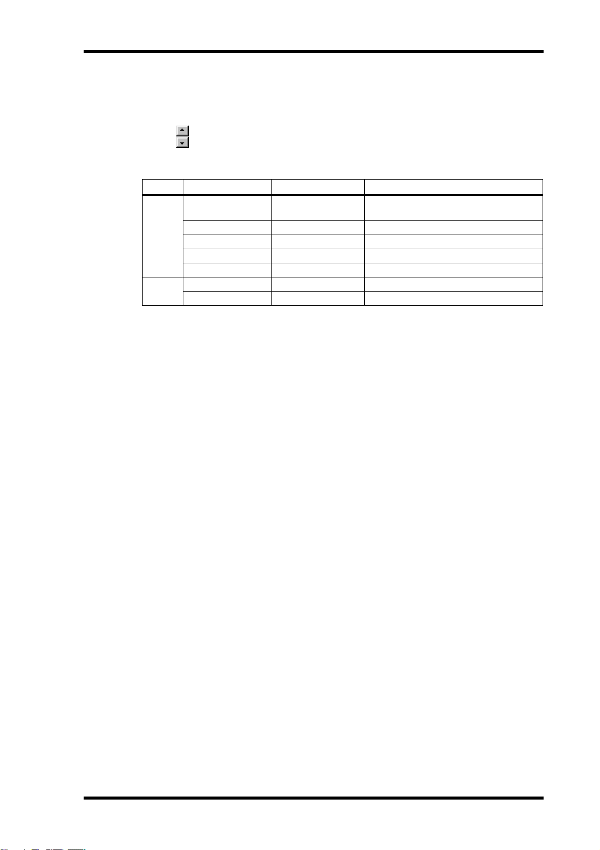
For components with five or more outputs (i.e., five or more bus level controls
per input channel), the bus level controls in the IN section can be scrolled up or
down by clicking the two arrow buttons shown here.
The parameter ranges for the Matrix Mixers are as follows.
Section Parameter Range Description
Adjusts the level of each input channel signal that is fed to each output channel
IN
OUT
Bus level
PHASE
SOLO
ON/OFF
Fader
ON/OFF
Fader
Mute to +10.0 dB
NOR/REV Inverts each input channel signal
ON/OFF Solos each input channel
ON/OFF Mutes each input channel
Mute to +10.0 dB Adjusts the level of each input channel
ON/OFF Mutes each output channel
Mute to +10.0 dB Adjusts the level of each output channel
For Matrix Mixer components with more than four inputs or outputs, channels are
arranged into pages consisting of four channels. Previously, channels were arranged
into pages consisting of six channels.
DME32—V1.5 Owner’s Manual Supplement
4
Stereo PEQ & GEQ Components
The five new stereo PEQ (parametric equalizer) and three new stereo GEQ (graphic
equalizer) components make it easier to process stereo signals. Essentially these are stereo versions of the existing EQ components.
PEQ
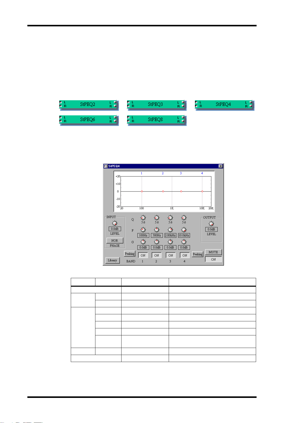
The five stereo PEQ components are shown below.
Each stereo PEQ component features two inputs and two outputs.
Each PEQ control window features an EQ graph and INPUT, EQ BAND, and OUTPUT sections. Since the only difference between all the stereo PEQ components is the
number of bands, only the stereo 4 BAND PEQ control window is shown here.
The parameter ranges for the stereo PEQ components are as follows.
Section Parameter Range Description
ON/OFF
INPUT
EQ BAND
OUTPUT LEVEL
MUTE
1. Top and bottom bands only.
DME32—Owner’s Manual Supplement
LEVEL
PHASE
Q
F
G
ON/OFF
1
Type
ON/OFF Turns the component on and off
Mute to 0.0 dB Adjusts the input signal level
NOR/REV Inverts the input signal
10–0.10 Adjusts the selectivity of each band
20.0 Hz–20.0 kHz Adjusts the frequency of each band
–15 dB to +15 dB Adjusts the gain of each band
ON/OFF Turns each band on and off
Peaking/L.Shelf or
H.Shelf
Mute to 0.0 dB Adjusts the output signal level
ON/OFF Mutes the output
Sets the filter type for the band

The EQ graph at the top of the window displays the EQ settings graphically, as shown
in the following example. The number of each EQ band appears along the top of the
graph.
5
In addition to using the rotary controls, the frequency (F) and gain (G) parameters for
each band can be set by dragging the small circles on the EQ graph. When the cursor is
placed over a circle, it changes to a hand and the curve can then be dragged to achieve
the required setting.
DME32—V1.5 Owner’s Manual Supplement
 Loading...