


10
5
0
5
10
20
30
40
50
60
10
5
0
5
10
20
30
40
50
60
10
5
0
5
10
20
30
40
50
60
10
5
0
5
10
20
30
40
50
60
10
5
0
5
10
20
30
40
50
60
10
5
0
5
10
20
30
40
50
60
10
5
0
5
10
20
30
40
50
60
10
5
0
5
10
20
30
40
50
60
10
5
0
5
10
20
30
40
50
60
88
MAIN
7
6
5
4
3
2
1
TOUCH
TURN
AND
PHONES
LEVEL
1010
CUSTOM 1
CUSTOM 2
OUTPUT
FX/MON
INPUT 1-8
INPUT 9-16
BANK / CH
FADER BANK
DAW
REC
USER DEFINED KEYS
2
4
6
>
rr
r
1
3
5
<
ee
DIGITAL MIXING CONSOLE
Reference Manual
EN

Table of contents
Table of contents
Introduction 10
About the Product...................................................................................10
Structure of this manual...........................................................................11
Notation.. ..............................................................................................12
Structure of the utility software................................................................13
Firmware updates...................................................................................14
Trademarks............................................................................................15
Controls and functions 16
Top panel...............................................................................................16
Overview of the top panel.. ..................................................................................................................................................... 16
Display and [TOUCH AND TURN] knob.. ................................................................................................................................. 18
CHANNEL STRIP section.. ........................................................................................................................................................19
[MAIN] section.. ........................................................................................................................................................................20
[FADER BANK] section.............................................................................................................................................................. 21
[USER DEFINED KEYS] section................................................................................................................................................. 22
[HOME] key.. .............................................................................................................................................................................23
[PHONES] section.. .................................................................................................................................................................. 24
USB connector.. .......................................................................................................................................................................25
Rear panel..............................................................................................26
Side panel.. ............................................................................................ 29
Connections 30
Analog connections.. ...............................................................................30
Analog input connections........................................................................................................................................................ 30
Analog output connections.. ...................................................................................................................................................31
Dante Network Connections.. ...................................................................32
I/O device connections.. ..........................................................................................................................................................32
Dante Auto Setup Function.. ...................................................................................................................................................33
Daisy chain connections.......................................................................................................................................................... 34
Star connections.. ....................................................................................................................................................................36
Redundant connections.. ........................................................................................................................................................38
2

Table of contents
Overview of screens 41
Breakdown of screens..............................................................................41
Basic operation of screens........................................................................43
Universal screen operations......................................................................46
Menus.. ..................................................................................................................................................................................... 46
SOFT KEYBOARD screen.. ........................................................................................................................................................ 48
Operating buttons and sliders.. .............................................................................................................................................. 49
Screen functions and names 52
Toolbar.................................................................................................. 52
SCENE screen..........................................................................................53
SCENE screen.. .........................................................................................................................................................................53
SCENE EDIT screen................................................................................................................................................................... 56
FADE TIME screen..................................................................................................................................................................... 57
METER screen.. ....................................................................................... 59
RECORDER Screen................................................................................... 63
RECORDER (TITLE LIST) screen.. .............................................................................................................................................63
RECORDER (INPUT/OUTPUT) screen.. ....................................................................................................................................67
RECORDER PATCH screen........................................................................................................................................................ 69
PLAYBACK PATCH screen......................................................................................................................................................... 70
MONITOR screen.. ...................................................................................72
MONITOR (CUE/MONITOR) screen.. ........................................................................................................................................72
MONITOR (OSCILLATOR) screen.............................................................................................................................................. 74
3

Table of contents
SETUP screen..........................................................................................76
SETUP screen.. .........................................................................................................................................................................76
USER DEFINED KEYS screen.. .................................................................................................................................................. 78
SAVE/LOAD screen.. .................................................................................................................................................................81
LOAD SELECT screen................................................................................................................................................................ 84
PREFERENCES screen.. ............................................................................................................................................................85
CUSTOM FADER BANK screen.................................................................................................................................................. 91
MIDI (Setup) screen.................................................................................................................................................................. 93
MIDI (Program Change) screen................................................................................................................................................ 95
MIDI (Control Change) screen.................................................................................................................................................. 98
WORD CLOCK screen.............................................................................................................................................................. 101
RECALL SAFE screen.. ............................................................................................................................................................ 102
BUS SETUP screen.. ...............................................................................................................................................................104
MUTE GROUP ASSIGN screen.. ..............................................................................................................................................105
PATCH screen.. .......................................................................................................................................................................107
DANTE (Setup) screen (DM3 only).. .......................................................................................................................................109
DANTE PATCH screen............................................................................................................................................................. 112
DANTE PATCH LIBRARY screen.............................................................................................................................................. 114
DANTE AUTO SETUP screen.. ................................................................................................................................................ 118
DANTE (I/O Device) screen..................................................................................................................................................... 121
CH LINK screen....................................................................................................................................................................... 123
CH LINK SET screen................................................................................................................................................................ 126
BRIGHTNESS screen............................................................................................................................................................... 127
NETWORK (For Mixer Control) screen.. .................................................................................................................................129
NETWORK (For Device Control) screen (DM3 only).. ............................................................................................................131
TIME screen.. ..........................................................................................................................................................................133
LOG screen.. ........................................................................................................................................................................... 135
ABOUT screen......................................................................................................................................................................... 136
CONSOLE LOCK screen.. ........................................................................................................................................................138
LOGIN screen.. ......................................................................................139
LOGIN screen.......................................................................................................................................................................... 139
CONSOLE LOCK screen.. ........................................................................................................................................................141
USER ACCOUNT screen.......................................................................................................................................................... 142
ACCESS PERMISSION screen.. ...............................................................................................................................................144
HOME screen 145
HOME screen.........................................................................................145
4

Table of contents
SELECTED CHANNEL section....................................................................148
SELECTED CHANNEL section................................................................................................................................................. 148
CH 1-16, ST IN, FX RTN 1-2.. ...................................................................................................................................................149
FX BUS 1-2.. ............................................................................................................................................................................ 151
MIX 1-6.. ..................................................................................................................................................................................152
MATRIX 1-2.............................................................................................................................................................................. 154
ST L/R...................................................................................................................................................................................... 156
CH STRIP section.. .................................................................................158
CH STRIP section.................................................................................................................................................................... 158
CH 1-16, ST IN, FX RTN 1-2.. ...................................................................................................................................................159
FX BUS 1-2.. ............................................................................................................................................................................ 161
MIX 1-6 and MATRIX 1-2.......................................................................................................................................................... 162
ST L/R...................................................................................................................................................................................... 163
FADER section.......................................................................................164
DAW REMOTE screen 165
DAW REMOTE screen.. ............................................................................165
Channel-specific screens 169
INPUT screen.. ......................................................................................169
INPUT CH PATCH screen..........................................................................174
EQ screen.. ...........................................................................................176
DYN1 (GATE/DUCKING) screen..................................................................181
DYN2 (COMP) screen...............................................................................184
DELAY screen.. ......................................................................................187
FX screen..............................................................................................189
EFFECT TYPE screen...............................................................................192
SEND TO Screen.....................................................................................193
ASSIGN screen.......................................................................................195
CH VIEW screen......................................................................................197
CH VIEW screen.. .................................................................................................................................................................... 197
CH 1-16, ST IN, FX RTN 1-2.. ...................................................................................................................................................199
MIX 1-6.. ..................................................................................................................................................................................201
FX BUS 1-2.. ............................................................................................................................................................................ 203
MATRIX 1-2.............................................................................................................................................................................. 205
STEREO...................................................................................................................................................................................207
5

Table of contents
CH NAME screen.....................................................................................209
GEQ screen.. .........................................................................................211
OUTPUT screen.. ...................................................................................214
OUTPUT CH PATCH screen.......................................................................217
SEND FROM screen.................................................................................219
LIBRARY screen.. ................................................................................... 221
Other fixed display areas 225
SENDS ON FADER area............................................................................225
ADMIN area...........................................................................................226
CHANNEL NAME area..............................................................................227
MAINTENANCE screen 229
MAINTENANCE screen.............................................................................229
Initialize All Memory screen.. .................................................................. 230
Initialize Current Memory screen.............................................................231
Initialize Dante screen (DM3 only)............................................................232
Input Port Trim screen.. .........................................................................233
Output Port Trim screen.........................................................................234
Fader Calibration screen.........................................................................235
Operating Screens 236
SCENE screen........................................................................................236
Saving a Scene.. ..................................................................................................................................................................... 236
Recalling a Scene.. .................................................................................................................................................................238
Editing a Scene....................................................................................................................................................................... 240
Setting the fade time for a scene.. ........................................................................................................................................ 241
RECORDER screen.................................................................................. 244
Selecting input for recording.. .............................................................................................................................................. 244
Recording.. .............................................................................................................................................................................246
Playing from USB storage...................................................................................................................................................... 247
Configuring the output of playback.. ....................................................................................................................................248
6

Table of contents
MONITOR screen....................................................................................249
Checking the CUE signal.. ......................................................................................................................................................249
Checking the MONITOR signal............................................................................................................................................... 250
Configuring the oscillator......................................................................................................................................................252
SETUP screen........................................................................................254
Assigning functions to [USER DEFINED KEYS].. ....................................................................................................................254
Configuring a CUSTOM FADER BANK.. ..................................................................................................................................256
Recalling a CUSTOM FADER BANK.. ...................................................................................................................................... 257
Patching in/output................................................................................................................................................................. 258
Configuring channel links...................................................................................................................................................... 259
Using the recall safe function................................................................................................................................................260
Assigning channels to mute groups.. ....................................................................................................................................262
LOGIN screen.. ......................................................................................264
Applying access permissions for guest users.. .....................................................................................................................264
HOME screen.........................................................................................265
Copying settings from one channel and pasting them to another...................................................................................... 265
DAW REMOTE screen.. ............................................................................269
For configuring a USB MIDI port............................................................................................................................................ 269
Channel-specific screens.........................................................................270
Adjusting EQ in manual mode............................................................................................................................................... 270
Adjusting EQ in 1-knob mode................................................................................................................................................ 272
Configuring the HPF............................................................................................................................................................... 275
Configuring GATE/DUCKING.................................................................................................................................................. 276
Adjusting the compressor in manual mode.. ....................................................................................................................... 277
Adjusting the compressor in 1-knob mode.. ........................................................................................................................ 278
Setting effects.. ......................................................................................................................................................................279
Adjusting the send to MIX/MATRIX BUS level.. ..................................................................................................................... 281
Setting the send to FX BUS level.. .........................................................................................................................................283
Adjusting the send to FX/MIX/MATRIX BUS level with faders.. ............................................................................................ 285
Using GEQ............................................................................................................................................................................... 286
Using faders to adjust GEQ.. ..................................................................................................................................................287
Configuring mute safe.. ......................................................................................................................................................... 288
Setting the send levels from output channels (MIX, STEREO) to MATRIX.. .........................................................................289
Recall presets.. .......................................................................................................................................................................290
Editing presets.. ..................................................................................................................................................................... 291
MAINTENANCE screen.............................................................................293
How to display and use the MAINTENANCE screen.............................................................................................................. 293
Calibrating faders................................................................................................................................................................... 294
If a fader must be calibrated again.. ..................................................................................................................................... 296
7

Table of contents
DM3 Editor 297
DM3 Editor............................................................................................297
Names of parts of the Editor....................................................................298
Menu bar..............................................................................................300
File menu................................................................................................................................................................................ 300
Manage Library/Scene screen.. .............................................................................................................................................302
Ch Names screen.................................................................................................................................................................... 305
Setup menu.. ..........................................................................................................................................................................308
Window menu.. ......................................................................................................................................................................309
Help menu.. ............................................................................................................................................................................310
Editor area............................................................................................311
HOME/LIBRARY/CH NAMES area.. .........................................................................................................................................311
CONNECT area.. ..................................................................................................................................................................... 312
FADER BANK area................................................................................................................................................................... 313
FX area.. ..................................................................................................................................................................................314
MUTE area.. ............................................................................................................................................................................ 315
MENU area..............................................................................................................................................................................316
SENDS ON FADER area........................................................................................................................................................... 317
CH STRIP area.........................................................................................................................................................................318
MAIN/FX RTN/ST IN STRIP area.. ...........................................................................................................................................319
Using the Editor 320
Overview of using the Editor...................................................................320
Operations at startup of the Editor...........................................................321
Syncing the Editor and the console...........................................................322
The offline editing function of the Editor...................................................325
Appendix 326
Parameters...........................................................................................326
SAVE/LOAD Data.. .................................................................................................................................................................. 326
Functions that can be assigned to USER DEFINED KEYS.. ................................................................................................... 327
List of Parameters that can be Assigned to Control Change.. .............................................................................................331
Effect Parameters.. ................................................................................................................................................................ 332
Dante Auto Setup compatible model.. ................................................................................................................................. 339
Dante Auto Setup patches..................................................................................................................................................... 340
Default values of IN/OUT patches.. .......................................................................................................................................341
8

Table of contents
Comments............................................................................................342
Dante.. .................................................................................................................................................................................... 342
The 1-knob EQ mode mechanism.. .......................................................................................................................................344
The 1-knob COMP mode mechanism.................................................................................................................................... 345
Port to Port function.. ............................................................................................................................................................346
Materials..............................................................................................347
Product Specifications........................................................................................................................................................... 347
List of Messages.. ................................................................................................................................................................... 353
Troubleshooting.. .................................................................................................................................................................. 357
MIDI Data Format.. .................................................................................................................................................................358
Languages available for channel names.. ............................................................................................................................ 360
DM3 Editor shortcuts.. ...........................................................................................................................................................361
Data List.................................................................................................................................................................................. 362
Block Diagram.. ......................................................................................................................................................................363
9

Introduction > About the Product
Introduction
About the Product
Differences with DM3
DM3 is compatible with the Dante audio network. DM3 STANDARD can only be used as a standalone product.
NOTE
Unless illustrated otherwise, use those of the DM3.
Target User
This product is geared toward people accustomed to mixing the audio of PA systems, such as in hall or for
events.
Purpose
This product is used for mixing multiple sources of sound, such as live performances of bands, corporate
events or producing music.
10

Introduction > Structure of this manual
Structure of this manual
DM3 Series manuals can be downloaded as a PDF from the Yamaha Pro Audio website. Manuals can also be
viewed in the HTML format.
https://www.yamahaproaudio.com/
Owner’s Manual
n
The owner’s manual primarily explains the name of parts of the panel and their basic operation.
DM3 Series Reference Manual (This Manual)
n
This manual primarily explains functions in detail and how to apply them in operating the product. It also
explains how to operate the software (DM3 Editor) on a computer to make settings and operate the console.
https://manual.yamaha.com/pa/mixers/dm3/rm/
DM3 Editor Installation Guide
n
This explains the steps for installing DM3 Editor.
https://manual.yamaha.com/pa/mixers/dm3/ig/
DM3 StageMix User Guide
n
This explains how to use the iPad application to wirelessly control the DM3 Series.
https://manual.yamaha.com/pa/mixers/dm3/ug/
11

Introduction > Notation
Notation
(
In this DM3 Series reference manual, the switches on the panel are called “keys.” The control knobs on the
panel are all called “knobs.” Knobs may turn from a minimum to a maximum value, or turn endlessly.
(
The virtual buttons displayed on the display are called “buttons” and the knobs are called “knobs.”
Controls on the panel are written inside brackets [ ] to distinguish them from virtual buttons and knobs
displayed onscreen. (Example: [CUE] key) The section name may be written in front of the brackets for
some controls. (Example: USER DEFINED KEYS [A] key)
12

Introduction > Structure of the utility software
Structure of the utility software
Various utility software is available for the DM3 Series. Detailed information on the software is available on
the Yamaha Pro Audio website.
https://www.yamahaproaudio.com/
For information on how to download files, install software or make advanced settings, please refer to the
websites mentioned above and/or the installation guide of the program after downloading it.
DM3 Editor
n
This software allows you to make settings for and operate the console from your computer. Operations like
backing up unit settings and setting up a console without it present may also be done.
DM3 StageMix
n
This iPad application is for wirelessly controlling the DM3 Series system. A mixing engineer can operate
parameters directly from a location separated from the system, such as the position of a performer on-stage.
DM3 MonitorMix
n
This software is for smart devices to wirelessly control MIX sends of the DM3 series.
Yamaha Steinberg USB Driver
n
This is driver software for connecting a computer to the DM3 Series. It controls a maximum of 18IN/18OUT
audio signals with the DAW software or remotely controls the DAW software.
ProVisionaire Control
n
This Windows software allows the user to create a control panel that matches the installation environment
and operating methods and to control the device remotely.
ProVisionaire Touch
n
This iPad application allows the user to create a control panel that matches the installation environment and
operating methods and to control the device remotely.
13

Introduction > Firmware updates
Firmware updates
The specifications of the DM3 Series allow for firmware updates to the console to improve operability, add
functions and/or resolve problems.
Information on updating firmware is available on the following website.
https://www.yamahaproaudio.com/
For information on the updating procedure and settings for the console, please refer to the Firmware
Updating Guide on the website.
14

Introduction > Trademarks
Trademarks
(
The illustrations and screenshots in this manual are entirely for the purpose of explanation.
(
We bear no responsibility whatsoever for the effects or impacts of using the software or this manual.
(
Windows is a registered trademark in the United States and other countries of Microsoft Corporation of
the United States.
(
Mac and iPad are trademarks of Apple Inc. registered in the United States and other countries.
(
Mackie Control and HUI are registered trademark or trademarks of LOUD Technologies Inc.
(
The names and trade names in this manual are the registered trademarks or trademarks of the companies
involved.
(
The typefaces included herein are solely developed by DynaComware Taiwan Inc.
15

FX/MON OUTPUT
c
d
a
b
i
h
g
f
e
MAIN
Controls and functions > Top panel
Controls and functions
Top panel
Overview of the top panel
Following is an explanation of the functions and names of parts of the top panel of the DM3 Series.
a
Display
The display can be operated by touching it. (p.18)
b
[TOUCH AND TURN] Knob
Use when adjusting the selected parameter. (p.18)
16

Controls and functions > Top panel
c
CHANNEL STRIP section
This part corresponds to the channel module of a conventional analog mixer. It is for operating the main parameters
of the currently selected channel. (p.19)
d
[MAIN] section
This section is primarily for operating the STEREO channel. (p.20)
e
[USER DEFINED KEYS] section
Keys that operate functions assigned at the discretion of the user. A number of frequently used functions, such as tap
tempo, bookmarks, etc., are assigned by default. (p.22)
f
[HOME] key
Returns to the HOME screen. (p.23)
g
[FADER BANK] section
Switches the faders assigned to the panel. (p.21)
h
[PHONES] section
For monitoring the signal selected with MONITOR select, or the CUE signal via headphones. (p.24)
i
USB connector
This connector is for connecting a USB storage device. (p.25)
17

b
a
Controls and functions > Top panel
Display and [TOUCH AND TURN] knob
The display can be operated by touching it. Using the [TOUCH AND TURN] knob allows intuitive operation of
parameters.
a
Display
In addition to touch/double-touching it, the display can be operated by sliding, swiping and pinching in/out on it.
b
[TOUCH AND TURN] Knob
Operates the parameter selected on the display.
Related links
“Basic operation of screens”(p.43)
18

a
b
c
d
Controls and functions > Top panel
CHANNEL STRIP section
The CHANNEL STRIP section corresponds to the channel module of a conventional analog mixer and it
operates the main parameters of the selected channel. The channels assigned on the CUSTOM FADER BANK
screen can be customized.
a
[SEL] key
This key selects the channel to be operated. Pressing this key makes it light and that channel is selected on the
display as being subject to operation. With stereo channels, each press of the [SEL] key toggles between the L/R
channels.
b
[CUE] key
The [CUE] key selects the channel to monitor. It lights when the CUE is ON.
c
[ON] key
Toggles the channel ON/OFF. This key lights for channels that are ON. In the SENDS ON FADER mode, the signal sent
from that channel to the currently selected MIX BUS, FX BUS, or MATRIX BUS is toggled ON/OFF.
d
Fader
Faders adjust the signal level of the channel. In the SENDS ON FADER mode, it adjusts the send level from that
channel to the currently selected MIX BUS, FX BUS, or MATRIX BUS .
19

a
b
c
d
MAIN
Controls and functions > Top panel
[MAIN] section
The [MAIN] section is primarily for operating the parameters of the STEREO channel. The channels assigned
on the CUSTOM FADER BANK screen can be customized.
When using the normal FADER BANK, or a CUSTOM FADER BANK with MAIN assigned to it, it operates SEND
MAIN in the SENDS ON FADER mode.
a
[SEL] key
This key selects the STEREO channel to be operated. Each press of the [SEL] key toggles which of the L/R channels are
to be operated.
b
[CUE] key
The [CUE] key is for selecting the STEREO channel to monitor. The LED lights when CUE is ON.
c
[ON] key
Toggles the STEREO channel ON/OFF. This key lights when ON. To operate as SEND MAIN, toggle the send destination
bus ON/OFF in the SENDS ON FADER mode.
d
Fader
This adjusts the output level of the STEREO channel. To operate as SEND MAIN, adjust the send level to the send to
bus in the SENDS ON FADER mode.
20

FX/MON OUTPUT
c
a
e
d
b
f
Controls and functions > Top panel
[FADER BANK] section
The [FADER BANK] section switches the faders assigned to the panel. Selected keys light.
a
[INPUT 1-8] keys
Channel INPUT keys 1-8 are displayed in the CHANNEL STRIP section.
b
[INPUT 9-16] keys
Channel INPUT keys 9-16 are displayed in the CHANNEL STRIP section.
c
[FX/MON] key
ST IN, FX RTN 1-2, FX 1-2, MONITOR and STEREO are displayed in the CHANNEL STRIP section.
d
[OUTPUT] key
MIX 1-6 and MATRIX 1-2 are displayed in the CHANNEL STRIP section.
e
[CUSTOM 1] key
f
[CUSTOM 2] key
CUSTOM FADER BANK is displayed in the CHANNEL STRIP section and the [MAIN] section.
If [CUSTOM 1] key and [CUSTOM 2] key are pressed at the same time, the fader assigned on the panel
switches to DAW REMOTE BANK and the DAW REMOTE screen displayed. The DAW software can be controlled
remotely using the CHANNEL STRIP section or [USER DEFINED KEYS].
Related links
(
“CUSTOM FADER BANK screen”(p.91)
(
“Configuring a CUSTOM FADER BANK”(p.256)
(
“Recalling a CUSTOM FADER BANK”(p.257)
(
“DAW REMOTE screen”(p.165)
(
“For configuring a USB MIDI port”(p.269)
21

Controls and functions > Top panel
[USER DEFINED KEYS] section
Keys that operate functions assigned at the discretion of the user.
Frequently used functions, such as tap tempo, bookmarks, etc., are assigned by default.
NOTE
(
When DAW REMOTE BANK is selected in the [FADER BANK] section, the function of DAW REMOTE BANK is a fixed assigned.
(
To select DAW REMOTE BANK, press keys [CUSTOM 1] and [CUSTOM 2] in the [FADER BANK] section.
Related links
(
“USER DEFINED KEYS screen”(p.78)
(
“Assigning functions to [USER DEFINED KEYS]”(p.254)
22

Controls and functions > Top panel
[HOME] key
Press [HOME] key to return the display to the top HOME screen.
Pressing the [HOME] key while on the HOME screen switches the display to whatever has been configured
with Key Function on the PREFERENCE screen.
Related links
(
“HOME screen”(p.145)
(
“PREFERENCES screen”(p.85)
23

a
b
Controls and functions > Top panel
[PHONES] section
Either the signal selected with MONITOR select or the CUE signal can be monitored with headphones.
a
[PHONES] jacks
Jack for inserting the headphone plug.
b
[LEVEL] knob
This knob adjusts the signal level output from the [PHONES] jack.
24

Controls and functions > Top panel
USB connector
The USB connector is for connecting a USB storage device.
In addition to saving or importing data in a DM3 file, it can be used to play audio files saved on a USB storage
device or record the mixer output to an audio file.
NOTE
(
The supported format is FAT32.
(
The ACCESS indicator is displayed on the screen while accessing the device for saving, loading, deleting, etc. While displayed,
refrain from removing the USB storage device or turning off the power of the console. Doing so may damage the USB storage
device and/or damage the data on the console or on the USB storage device.
(
Some USB storage devices can be write-protected to prevent accidentally erasing data. If important data is on the device, use its
write-protect function to prevent overwriting data. Conversely, to save data, first make sure the write-protect function of the USB
storage device is unlocked.
(
Prior to removing the USB storage device, touch the remove USB storage device button on the tool bar. Remove the USB storage
device after the message indicating it is safe to do so is displayed.
Related links
(
“Toolbar”(p.52)
(
“RECORDER Screen”(p.63)
(
“SAVE/LOAD screen”(p.81)
25

d
c
e
a
b
gf
Controls and functions > Rear panel
Rear panel
Following is an explanation of the functions and names of parts of the rear panel of the DM3 Series.
a
[OMNI OUT] jacks
XLR-3-32 type output jacks for outputting analog audio signals. These jacks are primarily for outputting MIX channels
and STEREO channels.
b
[INPUT] jacks
Connects to devices like mikes and musical instruments.
(
1 - 12:
XLR-3-31 input jacks
(
13 - 16:
Combo jacks compatible with both XLR and TRS phone plugs.
c
Power switch
When the switch is on (|), the power turns ON.
When the switch is on (z), the power goes to standby.
NOTICE
(
If 10 seconds elapse since the last operation, the power switch goes to standby. The state just before the power switch
went to standby is saved, and the system recovers to it when power comes back on.
(
To turn the power back on from standby, wait about 6 seconds or so. Turning the power ON and OFF repeatedly may
cause a malfunction.
26

Controls and functions > Rear panel
d
[DC INPUT] connector
For connecting to the included power adapter. First connect this device to the power adapter and then plug it into
the electrical outlet.
WARNING
(
Only ever use the included power cord. Also, never use any other product with the included power cord. Damage,
overheating, and/or fire may result. The included power cord is designed specifically for Japan (up to 125 V).
CAUTION
(
Always put the console in standby prior to connecting or disconnecting the cord.
(
A small amount of electricity flows even when the power is OFF (on standby). When the product will not be used for a
long time, unplug the cord from the outlet.
e
Dante PRIMARY/SECONDARY connectors (DM3 only)
These connectors are for Dante audio network connections, such as I/O devices like the Tio1608-D. The connectors to
use are RJ-45 connectors that conform to etherCON CAT5e, made by Neutrik.
NOTICE
(
To prevent electromagnetic interference, use STP (Shielded Twisted Pair) cables. When using STP cables, make sure the
metal parts of connectors and shielded parts of cables are in contact with conductive tape or the like.
NOTE
Do not use the EEE function (*) of a network switch inside a Dante network. Power consumption settings are adjusted
automatically between switches that support the EEE function, but some switches do not correctly adjust these mutual
settings correctly. This means that in certain unfavorable cases with the Dante network, the EEE function of a switch might be
enabled, impairing the clock synchronization capability and causing audio to be interrupted. As such, please note the
following.
(
If using a managed switch, turn off the EEE function of all ports that use Dante. Do not use a switch that does not allow you
to turn off the EEE function.
(
If using an unmanaged switch, do not use a switch that supports the EEE function. Such switches cannot turn off the EEE
function.
*EEE (Energy Efficient Ethernet) function: A technology that reduces power consumption of an Ethernet device when network
traffic is sparse. It is also called “green Ethernet” or IEEE802.3az.
f
[USB TO HOST] connector
USB Type B Connector
The product functions as an up to 18 IN/18 OUT, 96 kHz/32-bit audio interface by connecting to a computer via USB
cables. It also allows control of DM3 series and remote control of DAW software by USB-MIDI.
It is necessary to install Yamaha Steinberg USB Driver in order to communicate with a computer.
NOTICE
(
Use USB cables under 3 m long.
(
Wait at least 6 seconds between unplugging and replugging USB cables.
27

Controls and functions > Rear panel
g
Network Connector
This is an RJ-45 connector for connecting to a computer. Use an ethernet cable (CAT5e or better recommended).
NOTICE
(
To prevent electromagnetic interference, use STP (Shielded Twisted Pair) cables.
28

a
Controls and functions > Side panel
Side panel
The functions and names of parts of the side panel of a DM3 series are explained here.
a
Vent holes
The product is equipped with a cooling fan to prevent the inside from getting too hot. When it gets too hot inside, the
fan starts automatically. Both sides have vent holes.
CAUTION
Avoid blocking the vent holes of the product (heat dissipation slits). If vent holes are covered, it may get too hot inside, resulting in
damage and/or fire.
29

Tio1608-D
Connections > Analog connections
Connections
Analog connections
Analog input connections
The INPUT jacks of I/O devices like the DM3 series are mainly for connecting mikes and line level equipment.
Switching of patches is configured on the SETUP screen → PATCH screen. Patch switching can also be made
from INPUT screen → INPUT CH PATCH screen.
Related links
(
“PATCH screen”(p.107)
(
“INPUT CH PATCH screen”(p.174)
(
“Default values of IN/OUT patches”(p.341)
30

Tio1608-D
Main speaker
Connections > Analog connections
Analog output connections
Signals such as the output signals of output-related channels (MIX, MATRIX, STEREO (L/R), monitor signals
(MONITOR OUT L/R channel) and direct output signals of INPUT channels) can be patched to the OMNI OUT
connectors of the DM3 series and OUTPUT jacks of I/O devices.
The top panel of the DM3 series is equipped with a PHONES OUT jack for monitoring, so the signal selected
as the monitor source can always be monitored. In addition, that same signal can be monitored over an
external speaker by assigning the MONITOR OUT L/R channel to the desired output jack.
Monitor speaker
Switching of patches is configured on the SETUP screen → PATCH screen. Patch switching can also be made
from OUTPUT screen → OUTPUT CH PATCH screen.
Related links
(
“PATCH screen”(p.107)
(
“OUTPUT CH PATCH screen”(p.217)
(
“Default values of IN/OUT patches”(p.341)
31

Connections > Dante Network Connections
Dante Network Connections
I/O device connections
A DM3 can be connected to a I/O device (such as Tio1608-D) in 2 ways--via a daisy chain or star connection.
In addition, devices with 2 ports, a main line (PRIMARY) and sub-line (SECONDARY) can be connected to each
other with a redundant connection, which is resistant to failures.
The DM3 can be easily configured with its Auto Setup function using a Dante patch to supported I/O devices.
Related links
(
“Dante”(p.342)
(
“Dante Auto Setup Function”(p.33)
(
“Daisy chain connections”(p.34)
(
“Star connections”(p.36)
(
“Redundant connections”(p.38)
32

Connections > Dante Network Connections
Dante Auto Setup Function
The Auto Setup function of DM3 automatically configures Dante patches for the DM3 to compatible devices
in the Dante network.
Instead of using external software like a Dante Controller, it makes it easy to set up patches between the DM3
console and compatible devices.
Refer to the related links for the Dante devices compatible with the Auto Setup function.
Related links
(
“Dante Auto Setup compatible model”(p.339)
(
“Dante Auto Setup patches”(p.340)
33

Connections > Dante Network Connections
Daisy chain connections
A daisy chain is one way of connecting devices like a string of beads. It is a simple network structure with no
need for network switches. It is used for simple systems with only a few connected devices.
The more devices are connected, the more latency is required. In addition, if a system failure occurs, such as
a disconnected cable, it cuts off the network at that point, and communication with further devices in the
chain is lost.
Example of connection of AUTO SETUP DM3 and I/O device
n
Make connections as follows using the Dante connector of an I/O device with the DM3.
PRIMARY
FX/MON OUTPUT
MAIN
DM3
Tio1608-D (UNIT ID:Y001)
1
2
DZR (UNIT ID:Y001)
1
DZR (UNIT ID:Y002)
Configuration of I/O devices
n
Configure as follows when connecting to Tio1608-D or DZR-D/DXS-XLF-D using the DM3 AUTO SETUP
function.
PRIMARY
SECONDARY
34

Connections > Dante Network Connections
[Configuration of Tio1608-D]
(
UNIT ID = 1
(
SECONDARY PORT = DAISY CHAIN
(
START UP MODE = REFRESH
(
QUICK CONFIG = OFF
[Configuration of DZR-D/DXS-XLF-D]
(
UNIT ID = any ID from 1-8
(
MODE (DANTE MODE) = STANDARD
When using Dante Controller instead of AUTO SETUP, configure each of the I/O devices according to their
instructions.
Configure the UNIT ID of DZR-D/DXS-XLF-D on the DANTE SETUP screen of the DZR-D/DXS-XLF-D speaker.
35

Connections > Dante Network Connections
Star connections
Star connection refers to a method of connecting devices with a network switch in the middle. It can be used
for a large network that requires a wide bandwidth by using a network switch that supports a Gigabyte
Ethernet network switch. We recommend having various network switch functions (such as clock
synchronization of any data line, or QoS that prioritizes voice transmission) for the purpose of controlling
and monitoring the network.
Example of connection of AUTO SETUP DM3 and I/O device
n
Make connections as follows using the Dante connector of an I/O device with the DM3.
Network switch
PRIMARY
FX/MON OUTPUT
MAIN
DM3
PRIMARY
Tio1608-D
(UNIT ID:Y001)
PRIMARY
1
DZR
(UNIT ID:Y001)
36
PRIMARY
1
DZR
(UNIT ID:Y002)

Connections > Dante Network Connections
Configuration of I/O devices
n
Configure as follows when connecting to Tio1608-D or DZR-D/DXS-XLF-D using the DM3 AUTO SETUP
function.
[Configuration of Tio1608-D]
(
UNIT ID = 1
(
SECONDARY PORT = DAISY CHAIN
(
START UP MODE = REFRESH
(
QUICK CONFIG = OFF
[Configuration of DZR-D/DXS-XLF-D]
(
UNIT ID = any ID from 1-8
(
MODE (DANTE MODE) = STANDARD
When using Dante Controller instead of AUTO SETUP, configure each of the I/O devices according to their
instructions.
Configure the UNIT ID of DZR-D/DXS-XLF-D on the DANTE SETUP screen of the DZR-D/DXS-XLF-D speaker.
37

Connections > Dante Network Connections
Redundant connections
Redundant connections entail a network consisting of 2 lines, a main line (PRIMARY) and a sub-line
(SECONDARY). Normally the PRIMARY line carries communications, but if a problem occurs, such as an
interruption to the PRIMARY line, then communications switch automatically to the SECONDARY line. A
network environment more resistant to failures can be built by connecting in this way in a star configuration
than by a network constructed in a daisy chain.
Example of connection of AUTO SETUP DM3 and I/O device
n
Make connections as follows using the Dante connector of an I/O device with the DM3.
38

Connections > Dante Network Connections
Network switch
PRIMARY
FX/MON OUTPUT
MAIN
SECONDARY
DM3
PRIMARY
SECONDARY
Tio1608-D
(UNIT ID:Y001)
DZR DZR
Network switch
Configuration of I/O devices
n
Configure as follows when connecting to Tio1608-D or DZR-D/DXS-XLF-D using the DM3 AUTO SETUP
function.
[Configuration of Tio1608-D]
(
UNIT ID = 1
(
SECONDARY PORT = REDUNDANT
39

Connections > Dante Network Connections
(
START UP MODE = REFRESH
(
QUICK CONFIG = OFF
[Configuration of DZR-D/DXS-XLF-D]
(
UNIT ID = any ID from 1-8
(
MODE (DANTE MODE) = STANDARD
When using Dante Controller instead of AUTO SETUP, configure each of the I/O devices according to their
instructions.
Configure the UNIT ID of DZR-D/DXS-XLF-D on the DANTE SETUP screen of the DZR-D/DXS-XLF-D speaker.
NOTE
(
HA remote cannot be operated from the SECONDARY side.
(
No SECONDARY function is available under DZR-D/DXS-XLF-D Dante.
40

c da
e
b
Overview of screens > Breakdown of screens
Overview of screens
Breakdown of screens
The display of the console can be broadly divided into 5 areas.
a
Tool bar (p.52)
b
Main area
c
SENDS ON FADER area (p.225)
d
ADMIN area (p.226)
e
Channel Name area (p.227)
Content displayed in main area
n
What is displayed in the main area changes according to what icons and/or channels are selected.
The channel setting status is displayed all together on the HOME screen. (p.145)
The HOME screen has 3 types of screen, which are displayed in units of 8 channels, or of 1 channel.
The display changes each time [HOME] key/HOME button is pressed.
41

30
40
50
60
SCENE
A00
Initial Data
CH 1
ch 1
∞
-
CH 2
ch 2
∞
-
CH 3
ch 3
∞
-
CH 4
ch 4
∞
-
CH 5
ch 5
∞
-
CH 6
ch 6
∞
-
CH 7
ch 7
∞
-
CH 8
ch 8
∞
-
Rev
Rev
Delay
Mix 1
Mix 2
Mix 3
Mix 4
Mix 5
Mix 6
Matrix 1
Matrix 2
Sends
7:10:29
FX 1
Delay
Moni
0.00
FX 2
0
OVR
3
6
9
12
15
18
24
ST L
L
R
Stereo
∞
-
CH 2
ch 2
CH 3
ch 3
CH 4
ch 4
CH 5
ch 5
CH 6
ch 6
CH 7
ch 7
CH 8
ch 8
ON
CUE
10
0
10
20
40
60
∞
-
CH 1
ch 1
ON
CUE
10
0
10
20
40
60
∞
∞
-
ON
CUE
10
0
10
20
40
60
∞
-
ON
CUE
10
0
10
20
40
60
∞
-
ON
CUE
10
0
10
20
40
60
∞
-
ON
CUE
10
0
10
20
40
60
∞
-
ON
CUE
10
0
10
20
40
60
∞
-
ON
CUE
10
0
10
20
40
60
∞
-
-
∞-∞-∞-∞-∞-∞-∞
-
30
40
50
60
SCENE
A00
Initial Data
CH 1
ch 1
∞
-
CH 2
ch 2
∞
-
CH 3
ch 3
∞
-
CH 4
ch 4
∞
-
CH 5
ch 5
∞
-
CH 6
ch 6
∞
-
CH 7
ch 7
∞
-
CH 8
ch 8
∞
-
Rev
Rev
Delay
Mix 1
Mix 2
Mix 3
Mix 4
Mix 5
Mix 6
Matrix 1
Matrix 2
Sends
7:09:22
FX 1
Delay
Moni
0.00
FX 2
0
OVR
3
6
9
12
15
18
24
ST L
L
R
Stereo
∞
-
ST
R safe
123456
1
1
5
FX1
∞
-
REV
FX2
∞
-
DLY
C
CH 1
ch 1
DELAY
M safe
0
IN 1
0.0
meter
RTA
DYN 1
0
DYN 2
EQ HPF
0
3
6
9
12
15
18
24
30
0
3
6
9
12
15
18
24
30
30
40
50
60
SCENE
A00
Initial Data
CH 1
ch 1
∞
-
CH 2
ch 2
∞
-
CH 3
ch 3
∞
-
CH 4
ch 4
∞
-
CH 5
ch 5
∞
-
CH 6
ch 6
∞
-
CH 7
ch 7
∞
-
CH 8
ch 8
∞
-
Rev
Rev
Delay
Mix 1
Mix 2
Mix 3
Mix 4
Mix 5
Mix 6
Matrix 1
Matrix 2
Sends
7:09:54
FX 1
Delay
Moni
0.00
FX 2
0
OVR
3
6
9
12
15
18
24
ST L
L
R
Stereo
∞
-
DELAY
-8
0
IN 1
DELAY
-8
0
IN 3
DELAY
-8
0
IN 4
DELAY
-8
0
IN 5
DELAY
-8
0
IN 6
DELAY
-8
0
IN 7
DELAY
-8
0
IN 8
DELAY
-8
0
IN 2
CH 2
ch 2
CH 3
ch 3
CH 4
ch 4
CH 5
ch 5
CH 6
ch 6
CH 7
ch 7
CH 8
ch 8
CH 1
ch 1
SELECTED CHANNEL
SECTION
CH STRIP SECTION
FADER SECTION
a
b
Overview of screens > Breakdown of screens
The configuration screen is for making advanced settings to the selected channel(s).
a
Navigation area
b
Details area
42

30
40
50
60
SCENE
A00
InitialData
CH1
ch1
∞
-
CH2
ch2
∞
-
CH3
ch3
∞
-
CH4
ch4
∞
-
CH5
ch5
∞
-
CH6
ch6
∞
-
CH7
ch7
∞
-
CH8
ch8
∞
-
Rev
Rev
Delay
Mix 1
Mix 2
Mix 3
Mix 4
Mix 5
Mix 6
Matrix 1
Matrix 2
Sends
7:09:22
FX1
Delay
Moni
0.00
FX2
0
OVR
3
6
9
12
15
18
24
STL
L
R
Stereo
∞
-
ST
Rsafe
123456
1
1
5
FX1
∞
-
REV
FX2
∞
-
DLY
C
CH1
ch 1
DELAY
Msafe
0
IN1
0.0
meter
RTA
DYN 1
0
DYN 2
EQ HPF
0
3
6
9
12
15
18
24
30
0
3
6
9
12
15
18
24
30
30
40
50
60
SCENE
A00
Initial Data
CH 1
ch 1
∞
-
CH 2
ch 2
∞
-
CH 3
ch 3
∞
-
CH 4
ch 4
∞
-
CH 5
ch 5
∞
-
CH 6
ch 6
∞
-
CH 7
ch 7
∞
-
CH 8
ch 8
∞
-
Rev
Rev
Delay
Mix 1
Mix 2
Mix 3
Mix 4
Mix 5
Mix 6
Matrix 1
Matrix 2
Sends
7:10:29
FX 1
Delay
Moni
0.00
FX 2
0
OVR
3
6
9
12
15
18
24
ST L
L
R
Stereo
∞
-
CH 2
ch 2
CH 3
ch 3
CH 4
ch 4
CH 5
ch 5
CH 6
ch 6
CH 7
ch 7
CH 8
ch 8
ON
CUE
10
0
10
20
40
60
∞
-
CH 1
ch 1
ON
CUE
10
0
10
20
40
60
∞
∞
-
ON
CUE
10
0
10
20
40
60
∞
-
ON
CUE
10
0
10
20
40
60
∞
-
ON
CUE
10
0
10
20
40
60
∞
-
ON
CUE
10
0
10
20
40
60
∞
-
ON
CUE
10
0
10
20
40
60
∞
-
ON
CUE
10
0
10
20
40
60
∞
-
-
∞-∞-∞-∞-∞-∞-∞
-
30
40
50
60
SCENE
A00
Initial Data
CH 1
ch 1
∞
-
CH 2
ch 2
∞
-
CH 3
ch 3
∞
-
CH 4
ch 4
∞
-
CH 5
ch 5
∞
-
CH 6
ch 6
∞
-
CH 7
ch 7
∞
-
CH 8
ch 8
∞
-
Rev
Rev
Delay
Mix 1
Mix 2
Mix 3
Mix 4
Mix 5
Mix 6
Matrix 1
Matrix 2
Sends
7:09:22
FX 1
Delay
Moni
0.00
FX 2
0
OVR
3
6
9
12
15
18
24
ST L
L
R
Stereo
∞
-
ST
R safe
123456
1
1
5
FX1
∞
-
REV
FX2
∞
-
DLY
C
CH 1
ch 1
DELAY
M safe
0
IN 1
0.0
meter
RTA
DYN 1
0
DYN 2
EQ HPF
0
3
6
9
12
15
18
24
30
0
3
6
9
12
15
18
24
30
30
40
50
60
SCENE
A00
Initial Data
CH 1
ch 1
∞
-
CH 2
ch 2
∞
-
CH 3
ch 3
∞
-
CH 4
ch 4
∞
-
CH 5
ch 5
∞
-
CH 6
ch 6
∞
-
CH 7
ch 7
∞
-
CH 8
ch 8
∞
-
Rev
Rev
Delay
Mix 1
Mix 2
Mix 3
Mix 4
Mix 5
Mix 6
Matrix 1
Matrix 2
Sends
7:09:54
FX 1
Delay
Moni
0.00
FX 2
0
OVR
3
6
9
12
15
18
24
ST L
L
R
Stereo
∞
-
DELAY
-8
0
IN 1
DELAY
-8
0
IN 3
DELAY
-8
0
IN 4
DELAY
-8
0
IN 5
DELAY
-8
0
IN 6
DELAY
-8
0
IN 7
DELAY
-8
0
IN 8
DELAY
-8
0
IN 2
CH 2
ch 2
CH 3
ch 3
CH 4
ch 4
CH 5
ch 5
CH 6
ch 6
CH 7
ch 7
CH 8
ch 8
CH 1
ch 1
SELECTED CHANNEL
SECTION
CH STRIP SECTION
FADER SECTION
Overview of screens > Basic operation of screens
Basic operation of screens
The display can be operated by touching it. You can also use the [TOUCH AND TURN] knob to fine tune
parameters. In addition to touch and double-touch, you can also slide, swipe, pinch-in and pinch-out the
screen.
Switching screens
n
Touching the box at the top of the screen switches to the configuration screen.
Press the HOME button/[HOME] key to return to the HOME screen.
NOTE
You can choose what is displayed on the HOME screen by selecting Key Function → [HOME] Key from SETUP screen → PREFERENCE
screen. When multiple items are selected, the display will change with each press of the HOME button/ [HOME] key.
43
n
On screens that have a scroll bar, sliding the screen up/down or left/right displays the next screen.
Swiping allows high-speed scrolling.
Scrolling

SCENE
A00
InitialData
7:12:25
CH6
CH7
ch7
CH8
ch8
Pre
Matrix..
MTRX2
Pre
Matrix..
MTRX1
SCENE
A00
InitialData
7:05:01
Overview of screens > Basic operation of screens
IN1
SEND TO
0
ON
-
∞
ON
ON
-
-
∞
-8
DELAY
C
Pre
CH1
MIX3
Mix 3
ch 1
CH1
CH2
-
∞
ch1
ch2
Operating the Q of EQ
n
Pre
Pre
MIX5
MIX4
Mix 5
Mix 4
CH3
-
-
∞
∞
ch3
ON
-
∞
∞
Pre
MIX6
Mix 6
CH4
CH5
-
∞
ch4
CH6
-
∞
ch5
ON
ON
-
-
∞
∞
Pre
Pre
MTRX2
MTRX1
Matrix..
Matrix..
CH7
-
-
∞
ch6
∞
ch7
FX1
Rev
Rev
FX2
Delay
Delay
Mix 1
Moni
Mix 2
Mix 3
Mix 4
Mix 5
Mix 6
Matrix 1
Matrix 2
Sends
CH8
ch8
0.00
OVR
0
3
6
9
12
15
18
24
30
40
50
60
R
L
STL
-
∞
-
∞
Stereo
When in the manual mode while on the EQ screen, selecting a handle and pinching in/out on it performs Q
operation on the selected handle.
FX1
REV
FX2
DLY
CH1
1
5
1
ST
123456
Rsafe
CH1
E
-
∞
0
-
∞
EQ HPF
Msafe
C
DELAY
IN1
Q F G
0.7 1.25k +12.0
ch 1
CH2
CH3
-
-
∞
ch1
∞
ch2
CH4
-
∞
ch3
ch4
RTA
DYN 1
0
0.0
meter
DYN 2
CH5
-
∞
CH6
-
∞
ch5
0
3
6
9
12
15
18
24
30
0
3
6
9
12
15
18
24
30
CH7
-
-
∞
ch6
∞
ch7
FX1
Rev
Rev
FX2
Delay
Delay
Mix 1
Moni
Mix 2
Mix 3
Mix 4
Mix 5
Mix 6
Matrix 1
Matrix 2
Sends
CH8
ch8
0.00
OVR
0
3
6
9
12
15
18
24
30
40
50
60
R
L
STL
-
∞
-
∞
Stereo
NOTE
This operation is not available in the 1-knob mode, which is for controlling multiple parameters with 1 knob. Select the manual mode
with the mode switching button at the top of the screen.
Operating parameters with the [TOUCH AND TURN] knob
n
As illustrated below, after touching (a) the desired parameter to select it, operate it with the [TOUCH AND
TURN] knob (b). The selected parameter is displayed with a pink frame.
44

DELAY
0
IN1
0.0
meter
RTA
DYN 1
0
DYN 2
Q F G
0.7 1.25k +12.0
EQ HPF
0
3
6
9
12
15
18
24
30
0
3
6
9
12
15
18
24
30
ST
Rsafe
123456
1
1
5
FX1
∞
-
REV
E
SCENE
A00
InitialData
CH1
ch1
∞
-
CH2
ch2
∞
-
CH3
ch3
∞
-
CH4
ch4
∞
-
CH5
ch5
∞
-
CH6
ch6
∞
-
CH7
ch7
∞
-
CH8
ch8
∞
-
FX2
∞
-
DLY
C
CH1
ch 1
Msafe
Rev
Rev
Delay
Mix 1
Mix 2
Mix 3
Mix 4
Mix 5
Mix 6
Matrix 1
Matrix 2
Sends
7:05:01
FX1
Delay
Moni
0.00
FX2
0
OVR
3
6
9
12
15
18
24
30
40
50
60
STL
L
R
Stereo
∞
-
Overview of screens > Basic operation of screens
NOTE
The 1-knob mode
(
The 1-knob mode was designed to make it easy to operate multiple parameters for the EQ and the Compressor via the [TOUCH
AND TURN] knob. When the 1-knob mode is active, the parameters cannot be operated individually. The 1-knob mode can be
turned ON/OFF from the EQ and Compressor screens.
45

Overview of screens > Universal screen operations
Universal screen operations
Menus
Swipe left on the menu swipe indicator on the right of the screen to open the menu.
This opens a menu of options for operating the current screen.
The items in the menu vary with the displayed screen. For information about each menu, refer to the
description for that screen.
46

a
b
Overview of screens > Universal screen operations
a
Menus
The items in the menu vary with the displayed screen. For information about each menu, refer to the description for
that screen.
b
Library button
Touch the Library button to open the channel presets LIBRARY screen.
47

c dfe
a b
Overview of screens > Universal screen operations
SOFT KEYBOARD screen
Titles and comments can be edited from the SOFT KEYBOARD screen. The content displayed varies with the
screen. The SOFT KEYBOARD screen displayed when saving a scene is described here as an example.
a
Cancel button
Cancels editing and goes back to the previous screen.
b
Title field
Enter a name for the scene.
c
Comment field
Enter any additional information.
d
OK button
Saves the results of editing.
e
Fade Time settings
Specifies fade time settings and switches fade times used in scenes ON/OFF. To display the FADE TIME screen, touch
the button on the right edge.
f
Keyboard
Enters letters that are touched.
48

Overview of screens > Universal screen operations
Operating buttons and sliders
Close button
n
Touch to close the current screen.
OK button
n
Applies current conditions.
Cancel button
n
Cancels operation(s) and returns to the previous screen.
Clear button
n
Clears entered information.
Jump button
n
Displays the relevant screen.
Slider
n
Touch to enable, indicated by flashing in pink.
Drag sliders on the display or turn the [TOUCH AND TURN] knob to make settings.
Pan slider
n
Touch to enable operation via the [TOUCH AND TURN] knob, indicated by flashing in pink.
49

Overview of screens > Universal screen operations
Balance slider
n
Touch to enable operation via the [TOUCH AND TURN] knob, indicated by flashing in pink.
Edit icon
n
Opens a screen for editing information, such as the keyboard screen.
Menu
n
Touch a button with [w] displayed on it to display the menu.
Text box
n
For text boxes that allow numeric entries, touch to enable changes, which is indicated by flashing in pink.
While flashing in pink, touch to open a screen for entering a numeric value.
The value can also be set by turning the [TOUCH AND TURN] knob.
For text boxes that allow text entries, touch to open the SOFT KEYBOARD screen.
ON and OFF
n
Touch to toggle a function between ON and OFF.
When ON (Example):
50

Overview of screens > Universal screen operations
When OFF (Example):
51

Screen functions and names > Toolbar
Screen functions and names
Toolbar
The toolbar is configured with frequently used functions and icons to screens for system settings. The
toolbar is always displayed, regardless of what is displayed in the main area.
a
a
Displays the SCENE screen. (p.53)
b
Displays the METER screen. (p.59)
c
Status indicator
Displays the status in the following 3 cases.
(
ACCESS :
While accessing the USB storage device plugged into the USB connector.
(
OSC :
When the oscillator is ON.
(
DAW :
When DAW and USB-MIDI are connected.
d
Displays the RECORDER screen. (p.63)
b c d e f g ih
j
e
Displays the MONITOR screen. (p.72)
f
Displays the SETUP screen. (p.76)
g
Displays the LOGIN screen. (p.139)
h
Displays the current time.
i
Remove USB storage button
Displayed when a USB storage device is connected.
Touch before removing the USB storage device.
j
The HOME button displays the HOME screen. (p.145)
It functions the same as the [HOME] key on the top panel.
NOTE
(
Touching any icon changes the display of the MAIN area.
(
To return to the previous screen, touch the icon again, or touch the close button [X] at top, right of the screen.
52

a
d
ec
b
Screen functions and names > SCENE screen
SCENE screen
SCENE screen
The SCENE screen is for managing previously saved mixer configurations, or “Scenes”.
When recalling a scene, you can exempt certain settings from being recalled (called “recall safe”).
a
Scene list selection button
Allows you to switch between the available scene lists.
b
Scene list
Displays a list of saved scenes.
You can touch a header in the list to sort the items by that header (except for Information).
To select a scene, simply touch it. The selected scene is highlighted, and can then be saved, recalled, or edited.
A green triangle is displayed in front of the scene that is currently recalled.
The Fade Time field indicates whether the Fade Time function is enabled or not and its set time.
A lock icon is displayed or cleared each time you touch the column. When the icon is displayed, the scene is writeprotected.
The last save date for a scene is displayed in the Date column.
53

a
b
c
d
Screen functions and names > SCENE screen
c
Store button
Saves the current mixer settings to the scene number selected in the scene list.
Touch to open the screen for editing the title and comments.
d
Recall button
Recalls the scene selected in the scene list.
e
Edit button
Touch to open the screen for editing the title and comments.
SCENE screen menu
n
Swipe left on the menu swipe indicator on the right of the SCENE screen to open the following menu.
a
b
c
d
Copy
Copies settings of the selected scene.
Cut
Cuts settings of the selected scene.
Paste
Pastes the copied or cut scene to the selected line.
Delete
Deletes the selected scene.
54

Screen functions and names > SCENE screen
Related links
(
“SCENE EDIT screen”(p.56)
(
“FADE TIME screen”(p.57)
(
“Saving a Scene”(p.236)
(
“Recalling a Scene”(p.238)
(
“Editing a Scene”(p.240)
(
“Setting the fade time for a scene”(p.241)
55

c
a b
Screen functions and names > SCENE screen
SCENE EDIT screen
The SCENE EDIT screen is for configuring the title, comments and fade time for a scene.
a
Title text box
Enter a name for the scene.
b
Comment text box
Enter any additional information about the scene.
c
Fade Time settings
Specifies fade time settings and switches fade times used in scenes ON/OFF. Touch the jump button to open the
FADE TIME screen.
Touch a text box, and then with it highlighted, the [TOUCH AND TURN] knob can be used.
Related links
“Editing a Scene”(p.240)
56

a
Screen functions and names > SCENE screen
FADE TIME screen
When on the FADE TIME screen, the channels to apply the fade time of a scene can be turned ON/OFF
individually.
a
Channel buttons
Turn the individual channels to reflect the fade time ON/OFF. When turned ON, a channel turns white.
FADE TIME screen menu
n
Swipe left on the menu swipe indicator on the right of the FADE TIME screen to open the following menu.
57

a
b
Screen functions and names > SCENE screen
a
All ON
Turns ON fade time for all channels.
b
All OFF
Turns OFF fade time for all channels.
Related links
“Setting the fade time for a scene”(p.241)
58

d e
a
b c
Screen functions and names > METER screen
METER screen
While on the METER screen, the IN/OUT levels of all channels can be displayed and the metering point (point
to detect levels) of level meters can be switched.
a
Input metering point selection menu
Select the metering point of the input level from the menu.
(
PRE HPF :
Just before the head amp (just before HPF)
(
PRE FADER :
Just before the fader
(
POST ON :
Right after the [ON] key
b
Output metering point selection menu
Select the metering point of the output level from the menu.
(
PRE EQ :
Just before EQ
(
PRE FADER :
Just before the fader
(
POST ON :
Right after the [ON] key
59

Screen functions and names > METER screen
c
Peak Hold button
When turned ON, it holds the peak of each meter. When turned OFF, the display of peak levels held to that point is
cleared. Both the input and output channels are affected when the Peak Hold button is turned ON/OFF.
NOTE
The function of switching the Peak Hold button ON/OFF can be assigned to [USER DEFINED KEYS].
d
Meters
Display the input and output levels of the channels.
60

Screen functions and names > METER screen
e
Meter display selection buttons
Allow you to select how many meters are displayed. 3 patterns are available.
61

Screen functions and names > METER screen
Related links
“USER DEFINED KEYS screen”(p.78)
62

fe g h i j k l m
Screen functions and names > RECORDER Screen
RECORDER Screen
RECORDER (TITLE LIST) screen
Available functions from the RECORDER (TITLE LIST) screen include playing song files (BGM and sound
effects) on the USB storage device plugged in the USB connector, or record a 2 MIX source ( STEREO or MIX
channel) to the USB storage device.
NOTE
(
Recording and playing cannot be done at the same time.
(
The signal being recorded cannot be input to the INPUT channel.
(
Only FAT32 formatted USB storage devices can be used. If needed, connect one to the USB connector (right side of top panel) and
format it from the menu on the SAVE/LOAD screen.
(
To record, use a USB storage device that can write at the speed of a HDD or SSD. Also, try recording on your USB storage device
ahead of time to make sure it can write fast enough.
(
To play MP3 files, they must have sample rates of 44.1 or 48 kHz and a bit rate of between 128 - 320 kbps. VBR (variable bit rate)
files can also be played, but song length and elapsed time are not displayed accurately.
(
To record MP3 files, they must have sample rates of 48 kHz and a bit rate of 128, 256 or 320 kbps.
(
To record WAV files, they must be recorded at 96 kHz and 24-bit or 48 kHz and 24-bit with the leader clock at 96 kHz, or 48 kHz and
24-bit with the leader clock at 48 kHz.
(
If the number of items, including that of folders exceeds 150, they cannot be displayed in the song list. If there are more than 150
songs, divide them into separate folders.
(
The maximum size for long recordings is 2 GB. To continue recording for a long time, split the data when it exceeds 2 GB.
a b c d
63

Screen functions and names > RECORDER Screen
a
Parent directory button
Displays the directory one level above the current directory.
b
Current directory
Displays the current directory path for the USB storage device directory.
c
USB storage device information
Displays the volume name of the USB storage device.
It also shows the amount and percentage of free space on the USB storage device.
d
File list
Displays the music files in the current directory.
You can click a header in the list to sort the items by that header.
Touch to select the name of a song file, and then play, pause or edit it.
If the check box is enabled, a file will be played when all songs are played.
The file name is displayed in the File Name column.
Artist information is displayed in the Artist field and length in the Time field.
If the number of items, including that of folders exceeds 150, they cannot be displayed in the song list and operations
e to m are not available.
In such case, “Recorder supports a maximum of 150 items in a folder. Please remove some files from this folder to
continue.” is displayed.
e
Follow playback button
During continuous playback, the current song is highlighted in the song list and this button turns the follow function
ON/OFF. When ON, selecting a different file turns the function OFF.
f
Song file information display/indicator
While playing a MP3 file, this shows its bit rate and playback position.
While playing a WAV file, this shows its sample rate and playback position.
While recording a MP3 file, this shows the elapsed recording time.
While recording a WAV file, this shows its sample rate and elapsed recording time.
64

Screen functions and names > RECORDER Screen
g
Playback mode selector button
Specifies the loop play mode setting.
Touch to toggle through the available modes.
plays one song one time (SINGLE).
plays one song repeatedly (SINGLE REPEAT).
Plays all the songs that are checked in the song list (ALL).
Plays all songs marked with a check mark repeatedly (ALL REPEAT).
h
PREVIOUS button
Touch to move playback position to the beginning of the current, or of the previous song.
i
Stop button
Stops recording or playing.
j
Play/pause button
Plays or pauses the song.
k
NEXT button
Starts playing at the beginning of the next song.
l
Record button
Activates the standby mode for recording. If the number of audio files inside a folder, including the number of folders,
exceeds 150, the record button will not work.
m
Edit file name button
Opens the SOFT KEYBOARD screen for editing the file name.
RECORDER screen menu
n
Swipe left on the menu swipe indicator on the right of the RECORDER screen to open the following menu.
65

a
b
Screen functions and names > RECORDER Screen
a
Make Dir
Creates a new directory in the current directory. If the number of audio files inside a folder, including the number of
folders, exceeds 150, Make Dir will not work.
b
Delete
Deletes the selected file.
Related links
(
“Recording”(p.246)
(
“Playing from USB storage”(p.247)
66
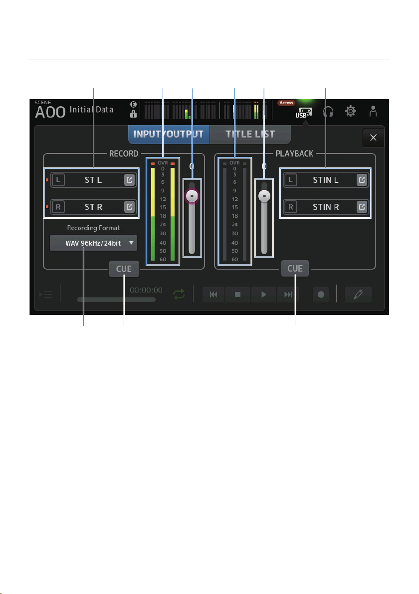
hg i
Screen functions and names > RECORDER Screen
RECORDER (INPUT/OUTPUT) screen
The RECORDER (INPUT/OUTPUT) screen is for operating RECORDER inputs and outputs.
a
b c fd e
a
Record source selection buttons
The channel name(s) to be recorded are displayed. The indicator lights if the recording source level is too high.
Touch the jump button to open the RECORDER PATCH screen.
b
RECORD level meter
Displays the recording volume level.
c
RECORD level slider
Sets the recording volume level.
d
Playback level meter
Displays the play volume level.
e
Play volume level slider
Sets the play volume level.
f
Playback channel selection button
Selects the channel to play the audio data of the USB storage device.
Touch the jump button to open the PLAYBACK PATCH screen.
67

Screen functions and names > RECORDER Screen
g
Recording format selection menu
Touch to open the menu and then select the recording format.
Choose from the following recording formats.
(
MP3 48 kHz / 128 kbps
(
MP3 48 kHz / 256 kbps
(
MP3 48 kHz / 320 kbps
(
WAV 48 kHz / 24 bit
(
WAV 96 kHz / 24 bit
NOTE
WAV 96 kHz / 24 bit can only be selected if the leader clock is on 96 kHz.
h
Record CUE button
Turns the CUE of the recording source ON and OFF.
i
Playback CUE button
Turns the CUE of the playback source ON and OFF.
Related links
(
“Playing from USB storage”(p.247)
(
“Selecting input for recording”(p.244)
(
“Configuring the output of playback”(p.248)
68

c
Screen functions and names > RECORDER Screen
RECORDER PATCH screen
The RECORDER PATCH screen is for selecting the channels to record.
a
b
a
Recording source channel name
Shows the channel name(s) to be recorded.
b
Patch port name
Shows the RECORDER INPUT name of the patch destination.
Pressing the L/R buttons toggles the selection L/R.
c
Recording source channel buttons
Use to select the channels to record.
69

c
Screen functions and names > RECORDER Screen
PLAYBACK PATCH screen
On the PLAYBACK PATCH screen, select the channel to play the audio data of the USB storage device.
a
b
a
PLAYBACK port name
Shows the PLAYBACK name of the patch source.
Pressing the L/R buttons toggles the selection L/R.
b
Patch destination channel name
Shows the channel name of the patch destination.
c
Patch destination channel selection button
Use to select the channels of the patch destination.
PLAYBACK PATCH screen menu
n
Swipe left on the menu swipe indicator on the right of the PLAYBACK PATCH screen to open the following
menu.
70

a
Screen functions and names > RECORDER Screen
a
Clear All
Clears patches (sets it to None).
71

i j k l
h
Screen functions and names > MONITOR screen
MONITOR screen
MONITOR (CUE/MONITOR) screen
The MONITOR (CUE/MONITOR) screen is for controlling the signals that are monitored with headphones or
near-field monitors.
It allows you to select the source to be continuously monitored and to change the monitor signal to mono or
add a delay. The CUE function can also be used for monitoring individual channels.
a
b c d f ge
a
CUE point selection buttons
Selects the point in the signal path to be monitored.
(
PFL :
Just before the fader
(
AFL :
After the fader
(
POST PAN :
After the pan
72

Screen functions and names > MONITOR screen
b
CUE Mode button
Used to switch the CUE mode.
(
Mix CUE :
Enables CUE for multiple channels.
(
Last CUE :
Enables CUE for the last channel selected.
c
PFL Trim setting text box
For adjusting the CUE monitor volume when PFL is selected. It can be set in the range of -30 to +20 dB.
Touch to display the input screen for each value.
d
Mono button
When turned ON, the monitor signal changes to mono.
e
Cue Interruption button
Toggles whether the CUE interrupts the monitor output.
f
Delay button
Delays the monitor signal.
Used when a time difference exists due to distance between the mixer and the FOH speaker.
g
Monitor output button
Turns the monitor output ON and OFF.
The signal is output to the [PHONES] connector regardless of this setting.
h
Monitor selection buttons
For selecting the monitor source.
i
Delay setting text box
Delay can be specified by frame, meter, sample, feet or ms.
The unit can be selected by PREFERENCE screen → Other → Display Delay Scale.
Touch to display the input screen for each value.
j
Monitor level meter
Displays the monitor level.
k
Clear CUE button
Clears all CUE as a batch.
l
Monitor level slider
Adjusts the monitor output level.
The signal is output to the [PHONES] connector regardless of this setting.
Related links
“Checking the CUE signal”(p.249)
73

e f
b c
d
a
Screen functions and names > MONITOR screen
MONITOR (OSCILLATOR) screen
The MONITOR (OSCILLATOR) screen allows you to check the oscillator settings and turn it ON/OFF. The DM3
series has a built-in oscillator, which can be used to output signals like sine waves or pink noise to any
channel for checking external devices and testing the characteristics of the venue.
a
Oscillator mode button
For selecting from the following 3 oscillators.
(
SINE WAVE :
Outputs a continuous sine wave.
(
PINK NOISE :
Outputs pink noise continuously.
(
BURST NOISE :
Outputs pink noise in bursts.
b
Parameter field
Available parameters are displayed according to the oscillator mode.
When the oscillator mode is set to SINE WAVE, this sets the oscillator frequency.
When the oscillator mode is BURST NOISE, this sets the Width (length of noise) and the Interval (time between
noises).
When the oscillator mode is PINK NOISE, nothing is displayed.
74

a
Screen functions and names > MONITOR screen
c
Oscillator output button
Turns the oscillator output ON and OFF. When ON, the oscillator signal is sent to the bus or input channel selected
with the assign buttons.
d
Oscillator assign buttons
Determine which channels the oscillator output signal is sent to. Touch buttons to specify the individual channel(s)
(multiple may be selected).
e
Oscillator output level meter
Displays the oscillator output level.
f
Oscillator output level slider
Adjusts the oscillator output level.
MONITOR (OSCILLATOR) screen menu
n
Swipe left on the menu swipe indicator on the right of the MONITOR (OSCILLATOR) screen to open the
following menu.
a
Clear All
Clears all assignments.
Related links
“Configuring the oscillator”(p.252)
75

o p q r sm n
b
f h j lc da e g i k
Screen functions and names > SETUP screen
SETUP screen
SETUP screen
The SETUP screen allows you to make general mixer settings, as well as those for patches, recall safe, userdefined key assignments, custom fader banks, and other preferences.
a
User Defined Keys icon
Displays the USER DEFINED KEYS screen. (p.78)
b
Save/Load icon
Displays the SAVE/LOAD screen. (p.81)
c
Preference icon
Displays the PREFERENCE screen. (p.85)
d
Custom Fader Bank icon
Displays the CUSTOM FADER BANK screen. (p.91)
e
MIDI icon
Displays the MIDI screen. (p.93)
76

Screen functions and names > SETUP screen
f
Word Clock icon
Displays the WORD CLOCK screen. (p.101)
g
Recall Safe icon
Displays the RECALL SAFE screen. (p.102)
h
Bus Setup icon
Displays the BUS SETUP screen. (p.104)
i
Mute Group icon
Displays the MUTE GROUP ASSIGN screen. (p.105)
j
Patch icon
Displays the PATCH screen. (p.107)
k
Dante Setup icon (DM3 only)
Displays the DANTE SETUP screen. (p.109)
l
Ch Link icon
Displays the CH LINK screen. (p.123)
m
Brightness icon
Displays the BRIGHTNESS screen. (p.127)
n
Network icon
Displays the NETWORK screen. (p.129)
o
Time icon
Displays the TIME screen. (p.133)
p
Log icon
Displays the LOG screen. (p.135)
q
About icon
Displays the ABOUT screen. (p.136)
r
Console Lock icon
Displays the CONSOLE LOCK screen. (p.141)
s
+48V Active button
Turns the console's phantom power feature ON and OFF.
NOTE
When this button is OFF, phantom power is not supplied, even if the +48V button on the INPUT screen of each channel is ON.
77

a b
Screen functions and names > SETUP screen
USER DEFINED KEYS screen
The USER DEFINED KEYS screen is for configuring functions assigned to [USER DEFINED KEYS].
78

Screen functions and names > SETUP screen
a
DAW Remote Keys Enable checkbox
When ON, [USER DEFINED KEYS] is fixed to the DAW REMOTE BANK function. When on DAW REMOTE BANK,
assignments cannot be made to [USER DEFINED KEYS].
NOTE
Functions of keys when on DAW REMOTE BANK
(
[1] key:
Go back one DAW bank or channel
(
[2] key:
Go forward one DAW bank or channel
(
[3] key:
Rewind DAW playback
(
[4] key:
Fast forward DAW playback
(
[5] key:
Stop DAW playing or recording
(
[6] key:
Start DAW playback
(
[1] + [2] key:
Switch between [1] and [2] key banks and channels
(
[3] + [4] key:
Turns DAW loop mode ON/OFF
(
[5] + [6] key:
Starts DAW recording
b
KEYS settings buttons (1-6)
Touch to open the screen (function selection screen) for selecting functions assigned to [USER DEFINED KEYS].
Function selection screen
n
When a function is selected on the Function selection screen, it displays candidates for Parameter 1, and
when functions of Parameter 1 are selected, candidates for Parameter 2 are displayed. If no candidates are
available for the next function after the selected function, candidates for Parameter 1 or Parameter 2 are not
displayed.
79

Screen functions and names > SETUP screen
Related links
(
“Assigning functions to [USER DEFINED KEYS]”(p.254)
(
“Functions that can be assigned to USER DEFINED KEYS”(p.327)
80

c d
e f g h
a
b
Screen functions and names > SETUP screen
SAVE/LOAD screen
Saved files and subdirectories are displayed on the SAVE/LOAD screen.
a
Parent directory button
Moves up one directory in the current directory.
The button greys out if the current directory is already at the top.
b
Current directory display
Displays the path of the current directory.
c
Volume name display
Displays the volume name and free space of the USB storage device.
The message “Calculating Size” is displayed while calculating the free space, and operations that involve access to
the USB storage device are not available.
The time required to calculate free space depends on the capacity of the connected USB storage device. It may take 3
minutes or more to calculate the free space of a large USB storage device.
81

Screen functions and names > SETUP screen
d
File list
Displays files and subdirectories saved on the USB storage device. When an item is highlighted, it indicates it is
selected and subject to subsequent operations.
Touch a header in the file list to sort by that header. The sort order toggles between ascending and descending each
time it is touched.
(
File Name :
Displays file and DM3 directory name, as well as an icon indicating the type.
(
Comment :
Displays comments entered in series files.
(
Date :
Displays the “date modified” of the file.
e
Save As button
Saves the internal settings of DM3 series as a new file.
f
Save button
Overwrites and saves the internal settings of the DM3 series.
g
Load button
Loads the selected DM3 series settings file.
The settings files of TF series can be loaded. When loaded, the file is converted for use by DM3 series.
Image files (png, bmp, jpg, jpeg files) displayed on the CONSOLE LOCK screen can also be loaded.
Press the Load button to open the LOAD SELECT screen.
h
Edit button
Opens the SOFT KEYBOARD screen for editing the file name and comments.
SAVE/LOAD screen menu
n
Swipe left on the menu swipe indicator on the right of the SAVE/LOAD screen to open the following menu.
82

b
a
f
c
e
d
Screen functions and names > SETUP screen
a
Copy
Copies the selected file.
b
Paste
Pastes the file to the current directory.
c
Make Dir
Creates a new directory.
d
Delete
Deletes the selected file.
e
Format
Formats the connected USB storage device.
f
Clear Lock Image
Clears images displayed on the CONSOLE LOCK screen.
Related links
“SAVE/LOAD Data”(p.326)
83

a b
c d
Screen functions and names > SETUP screen
LOAD SELECT screen
The LOAD SELECT screen allows you to configure what data is loaded when loading a DM3 series settings file.
a
All/Custom selection button
Switches the data to be loaded. When All is selected, all data is loaded.
When Custom is selected, checkboxes are displayed for choosing what will be loaded.
b
Data selection checkboxes
Check the boxes of items to be loaded.
The User Account checkbox is displayed for both All and Custom.
c
Load button
Touch to load the settings data.
d
Override Protected Scenes & Libraries checkbox
When ON, protected scenes & libraries are also erased when the settings data is loaded. To keep the protected scenes
and libraries, uncheck this to turn it OFF.
Related links
“SAVE/LOAD Data”(p.326)
84
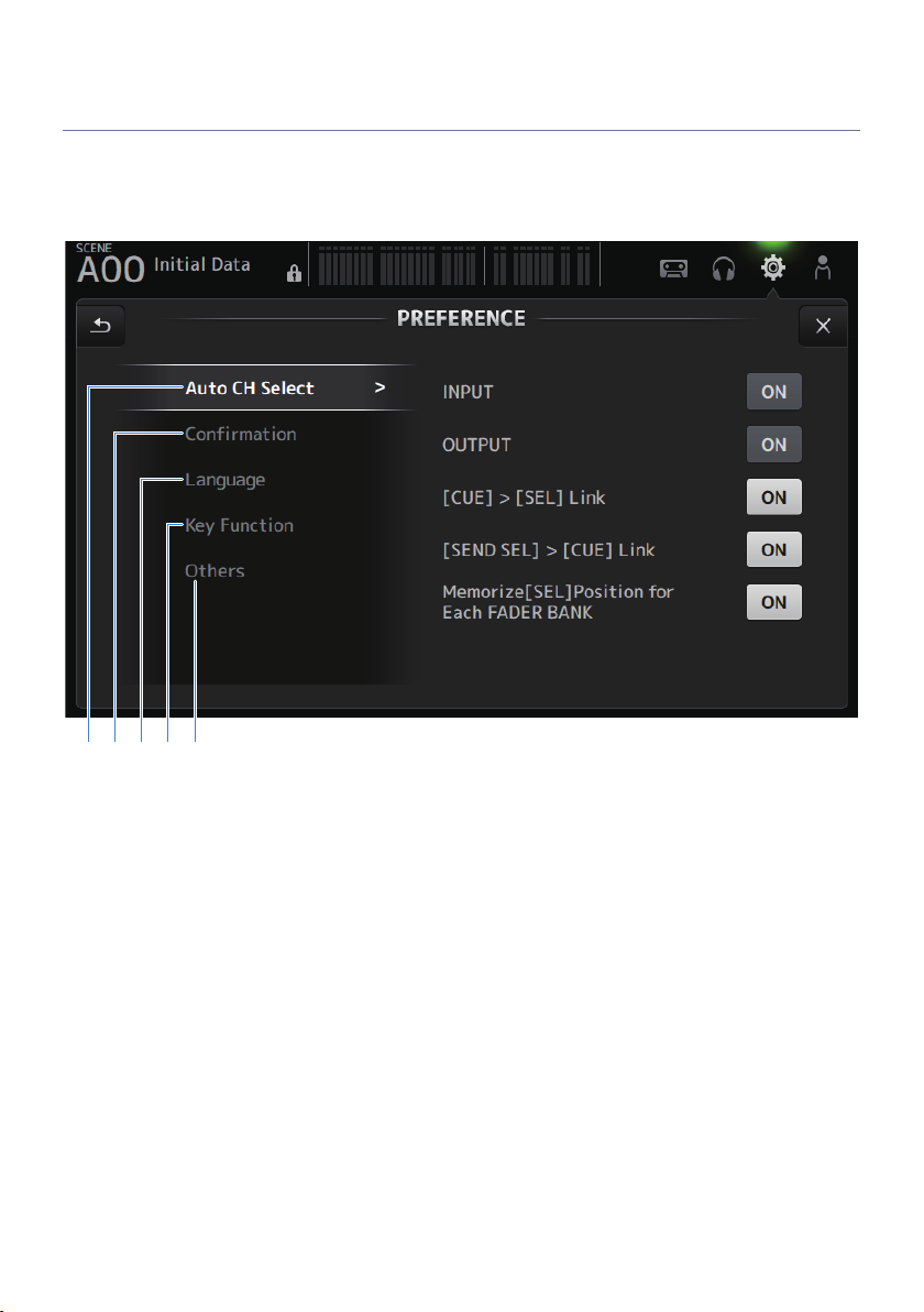
edcba
Screen functions and names > SETUP screen
PREFERENCES screen
The PREFERENCE screen makes settings for the operating environment, such as screen display, [SEL] key
behavior, etc.
85

Screen functions and names > SETUP screen
a
Auto CH Select section
(
INPUT/OUTPUT :
Sets whether to turn a channel on or not when its [ON] is turned on.
You can turn this feature ON and OFF independently for input channels and output channels.
(
[CUE] > [SEL] Link :
Sets whether to turn a channel on or not when its CUE is turned on.
(
[SEND SEL] > [CUE] Link :
Sets whether or not to link CUE with channel selection in the SENDS ON FADER mode.
(
Memorize[SEL] Position for Each FADER BANK :
Sets whether channel positions are remembered for each fader bank.
86

Screen functions and names > SETUP screen
b
Confirmation section
(
Store/Recall :
When ON, a confirmation message is displayed when store/recall operations are made, respectively.
(
INPUT Patch/OUTPUT Patch :
When ON, a confirmation message is displayed when patches are changed.
87

Screen functions and names > SETUP screen
c
Language section
(
Ch Name Language :
Selects the language to use for channel names.
NOTE
Use either DM3 Editor or DM3 StageMix for any language other than English.
88

Screen functions and names > SETUP screen
d
Key Function section
(
[TAP] Key Blink :
Turns ON/OFF the blinking of [USER DEFINED KEYS] keys to which Tap Tempo is assigned. Tapped tempos can be
input even when the key is OFF.
(
[HOME] Key :
Selects the HOME screen section to display when the top panel [HOME] key or display HOME button is pressed.
The sections that are turned on are displayed in order each time the [HOME] key/HOME button is pressed.
89

Screen functions and names > SETUP screen
e
Others section
(
Display Delay Scale :
The unit of delay displayed in the DELAY box can be set to sample, frame, meter, feet or ms.
(
Frame Rate :
Selects the frame rate for the delay setting in the frame unit.
(
Panel Assistance :
When Brightness is set to low, the panel LEDs glow dimly.
(
DAW Remote Mode :
Selects from DAW REMOTE BANK automation mode, Steinberg mode and Other mode (primarily ProTools).
90

c
Screen functions and names > SETUP screen
CUSTOM FADER BANK screen
CUSTOM FADER BANK allows you to assign channels freely. Two CUSTOM FADER BANK can be used. It also
sets the [MAIN] fader assignments for normal FADER BANK and DAW REMOTE BANK.
a b
a
CUSTOM FADER BANK selection buttons
For selecting the CUSTOM FADER BANK or MAIN to configure.
CUSTOM 1 and CUSTOM 2 provide complete freedom in assigning channels to faders.
MIXER MAIN sets the [MAIN] fader assignments for the normal FADER BANK.
REMOTE MAIN sets the [MAIN] fader assignments for DAW REMOTE MAIN.
b
Channel buttons
For selecting the channels to assign to the fader selected in c.
When MAIN is assigned to the [MAIN] fader, it becomes the send main when on SENDS ON FADER.
If you select None, nothing is assigned to the corresponding fader.
c
Fader buttons
For selecting the fader to assign channels to.
CUSTOM FADER BANK screen menu
n
Swipe left on the menu swipe indicator on the right of the CUSTOM FADER BANK screen to open the following
menu.
91

a
b
Screen functions and names > SETUP screen
a
Clear All
Clears all fader assignments (sets all to None).
b
Default
Resets all fader assignments to their defaults.
Related links
(
“Configuring a CUSTOM FADER BANK”(p.256)
(
“Recalling a CUSTOM FADER BANK”(p.257)
92

a b c d
Screen functions and names > SETUP screen
MIDI (Setup) screen
Screen for setting MIDI IN/OUT.
Make settings for each send (Tx) and receive (Rx).
a
Port selection buttons
For selecting the send/receive ports for MIDI.
(
USB :
USB connector
(
OFF :
Not in use
NOTE
The MIDI ports configured here are displayed as follows on your computer.
(
Scene, fader and channel ON/OFF control ports
Windows : Yamaha DM3-1
Mac : Yamaha DM3 Port1
(
DAW REMOTE port
Windows : Yamaha DM3-2
Mac : Yamaha DM3 Port2
b
Ch selection button
Selects the MIDI communication channel.
Select from Ch 1-16.
93

Screen functions and names > SETUP screen
c
Program Change selection button
Turns the program change communication signals ON/OFF.
d
Control Change selection button
Turns the control change communication signal ON/OFF.
94

a
b c d
Screen functions and names > SETUP screen
MIDI (Program Change) screen
Screen for assigning scene memories to MIDI program changes.
a
Program change list
Displays a list of scenes assigned to program changes.
(
Ch :
Displays the channel number.
Displays the bank number when Single and Bank Modes are selected.
(
No :
Displays the program change number.
(
Program Change Event :
Displays the titles of scenes assigned to program changes.
Touch to open the scene selection screen.
b
UP/DOWN buttons
Moves the channels or banks in the program change list up/down.
c
Program change selection buttons
Turns the program change communication signals ON/OFF.
Functions the same as the program change selection buttons on the Setup screen.
95
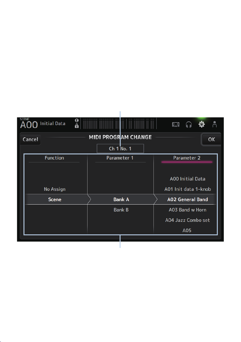
b
a
Screen functions and names > SETUP screen
d
Mode selection buttons
(
Single :
Mode for communicating via the MIDI channel set up on the Setup screen.
When Omni is selected under Single, all MIDI channel program changes are communicated.
Communication is only via the MIDI channel set up on the Setup screen.
When Bank is selected under Single, Bank Select for control changes is communicated.
(
Multi :
Mode for communicating via all MIDI channels.
Scene selection screen
n
The Scene selection screen is for assigning scene memories to program changes.
a
Program change display
Displays the MIDI channel numbers and program change numbers assigned to scenes.
Displays the bank and program change numbers when Single and Bank are selected.
b
Scene list
For selecting the scene assigned to program change.
If no scene is assigned, select No Assign via Function.
96

a
b
Screen functions and names > SETUP screen
MIDI PROGRAM CHANGE screen menu
n
Swipe left on the menu swipe indicator on the right of the MIDI PROGRAM CHANGE screen to open the
following menu.
a
Clear All
Clears all scenes assigned to program change.
b
Default All
Sets the program change assignment to the default.
97

a
b
Screen functions and names > SETUP screen
MIDI (Control Change) screen
The MIDI Control Change screen is the screen for assigning faders and/or [ON] keys to control changes.
a
Control change list
(
No. :
Displays the control change number.
(
Control Change Event :
Displays the parameter(s) assigned to control change numbers.
Touch to display the MIDI CONTROL CHANGE selection screen.
b
Control change selection button
Turns the control change communication signal ON/OFF.
Functions the same as the Control Change selection buttons on the Setup screen.
MIDI CONTROL CHANGE selection screen
n
The MIDI CONTROL CHANGE screen is for assigning parameters to control changes.
98

cb d
a
Screen functions and names > SETUP screen
a
Control change display
Displays the control number of the control change that assigns parameters.
b
Function
Selects the function to control.
If not assigning any parameters to a control change, select No Assign.
c
Parameter 1
For selecting input or output channel.
d
Parameter 2
For selecting the channel number.
MIDI CONTROL CHANGE screen menu
n
Swipe left on the menu swipe indicator on the right of the MIDI CONTROL CHANGE screen to open the
following menu.
99

a
b
Screen functions and names > SETUP screen
a
Clear All
Clears all settings assigned to a control change.
b
Default All
Sets all program change assignments to their defaults.
Related links
“List of Parameters that can be Assigned to Control Change”(p.331)
100
 Loading...