

Yamaha DBR15, DBR12, DBR10 User Manual
POWERED SPEAKER SYSTEM
DBR series
Technical Specifications
General Specifications
General DBR15 DBR12 DBR10
System Type 2-way, Bi-amp Powered Speaker, Bass-reflex Type
Frequency Range (-10dB) 50 Hz–20 kHz 52 Hz–20 kHz 55 Hz–20 kHz
Coverage Angle H90° x V60° Constant Directivity Horn
Crossover Type FIR-X Tuning (Linear Phase FIR Filter)
Crossover Frequency 2.1 kHz 2.1 kHz 2.1 kHz
Measured Maximum SPL (Peak) IEC noise@1m 132 dB SPL 131 dB SPL 129 dB SPL
Transducer DBR15 DBR12 DBR10
Diameter 15" Cone 12" Cone 10" Cone
LF
HF
Enclosure DBR15 DBR12 DBR10
Material, Color Plastic, Black
Floor Monitor Angle 50° Symmetrical 50° Symmetrical 50°
Dimensions (WxHxD, with rubber feet) 455 x 700 x 378 mm (17.9" x 27.6" x 14.9") 376 x 601 x 348 mm (14.8" x 23.7" x 13.7") 308 x 493 x 289 mm (12.1" x 19.4" x 11.4")
Net Weight 19.3 kg (42.6 lbs) 15.8 kg (34.8 lbs) 10.5 kg (23.2 lbs)
Handles Side x 2 Top x 1
Pole Socket 35mm
Rigging Points Bottom x 2, Rear x 1 (Fit for M8 x 15mm Eyebolts) Bottom x 2 (Fit for M8 x 15mm Eyebolts)
Optional Seaker Bracket BBS251, BCS251, BWS251-300, BWS251-400
Amplier DBR15 DBR12 DBR10
Amplifier Type Class-D
Power Rating *
1
Cooling Fan Cooling, 4 Speeds.
AD/DA 24bit 48kHz Sampling
HPF/LPF OFF, 100Hz, 120Hz, 24dB/Oct. HPF
DSP Preset D-CONTOUR: FOH/MAIN, MONITOR, OFF
Protection
Connectors
Input Impedance INPUT1 (XLR, Phone): 3 kΩ, INPUT2 (XLR, Phone, RCA Pin): 10 kΩ
Input Sensitivity (LEVEL: Maximum) INPUT1: LINE: 0 dBu, MIC: -32 dBu, INPUT2: 0 dBu
Input Sensitivity (LEVEL: Center) INPUT1: LINE: +10 dBu, MIC: -22 dBu, INPUT2: +10 dBu
Maximum Input Level INPUT1: LINE: +24 dBu, MIC: -8 dBu, INPUT2: +24 dBu
Controls LEVEL x2, LINE/MIC, HPF, D-CONTOUR, THRU/MIX, POWER
Idle Power Consumption 18 W 18 W
1/8 Power Consumption 74 W 60 W
Power Requirements 100 V, 100–120V, 220–240 V, 110/127/220 V (Brazil), 50/60 Hz
Voice coil 2.5" 2" 2"
Magnet Ferrite
Diaphragm 1.4" 1"
Type 1" Throat Compression Driver
Magnet Ferrite
Dynamic 1000 W (LF: 800 W, HF: 200 W) 700 W (LF: 500 W, HF: 200 W)
Continuous 465 W (LF: 400 W, HF: 65 W) 325 W (LF: 260 W, HF: 65 W)
Speaker Clip Limiting, Integral Power Protection, DC-fault
Amplifier Thermal, Output Over Current
Power Supply Thermal, Output Over Voltage, Output Over Current
Input Input1: Combo x1, Input2: Combo x1, RCA PIN x2 (Unbalanced)
Output Output: XLR3-32 x1 (CH1 Parallel Through or CH1+CH2 Mix)
ZN19540
0 dBu is referenced to 0.775Vrms.
1
Power Rating (120V, 25°C). This is total value of individual output power.
*
Specifications and descriptions in this owner’s manual are for information purposes only. Yamaha Corp. reserves the right to change or modify products or specifications at any time without prior notice. Since
specifications, equipment or options may not be the same in every locale, please check with your Yamaha dealer.
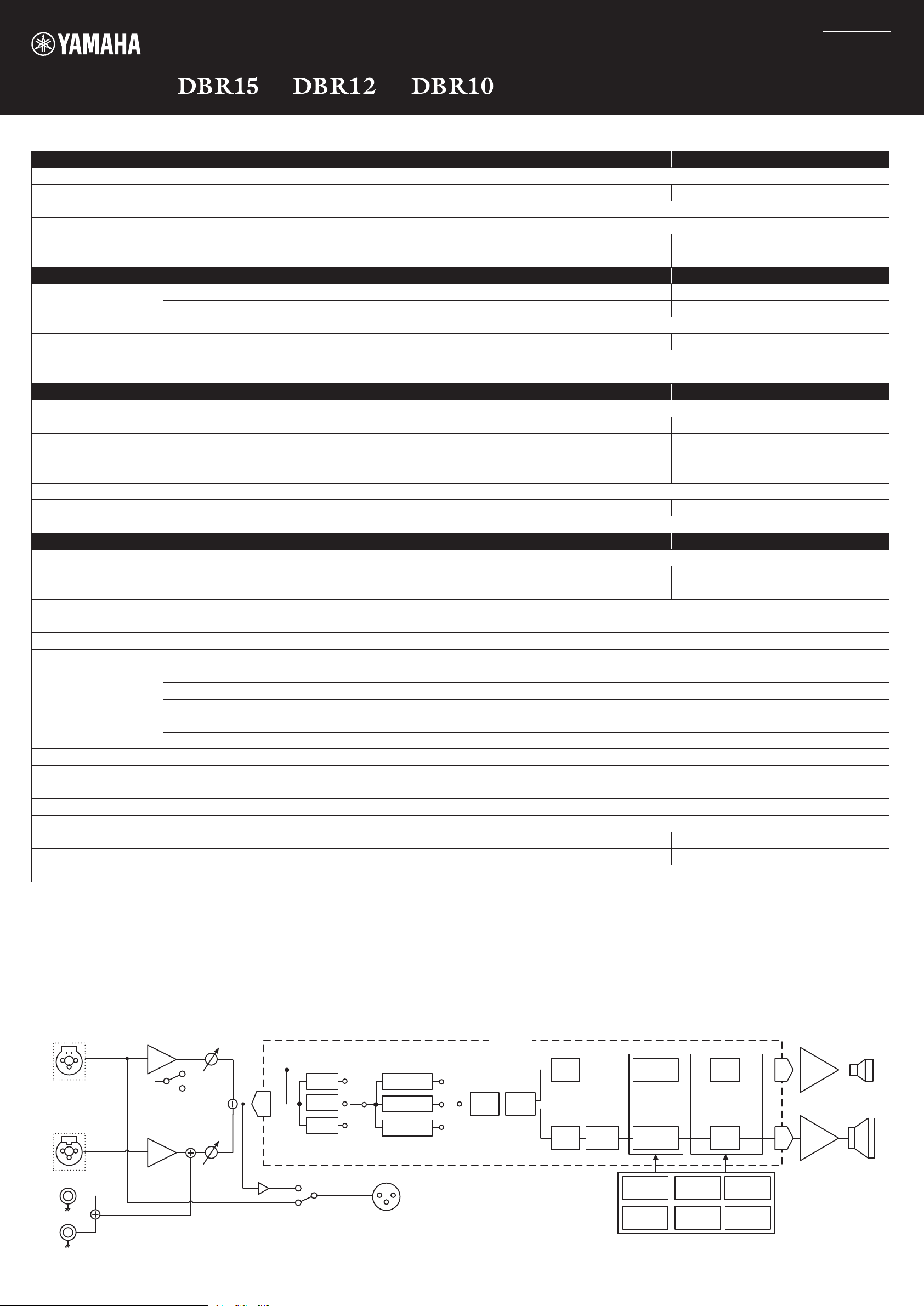
Block Diagram
INPUT
Combo
(Balance)
HA
1 (MIC/LINE)
MIC/LINE
Combo
(Balance)
HA
2 (LINE)
Pin
LEVEL
LEVEL
SIGNAL
AD
(CH1+2 MIX)
(CH1 THRU)
HPF
120Hz
100Hz
OFF
D-CONTOUR
FOH/MAIN
OFF
MONITOR
OUTPUT
EQ
DSP
FIR-X
HF
LF
EQ
Delay Limiter
EQ
Limiter
●LIMIT
Temp. DC-fault
Output
Voltage
Integral
Output
Power
Mute
●PROTECTION
Mute
Output
Current
On/Off
Mute
DA
DA
Amp.
(HF)
Amp.
(LF)
HF
LF
Protection Logic
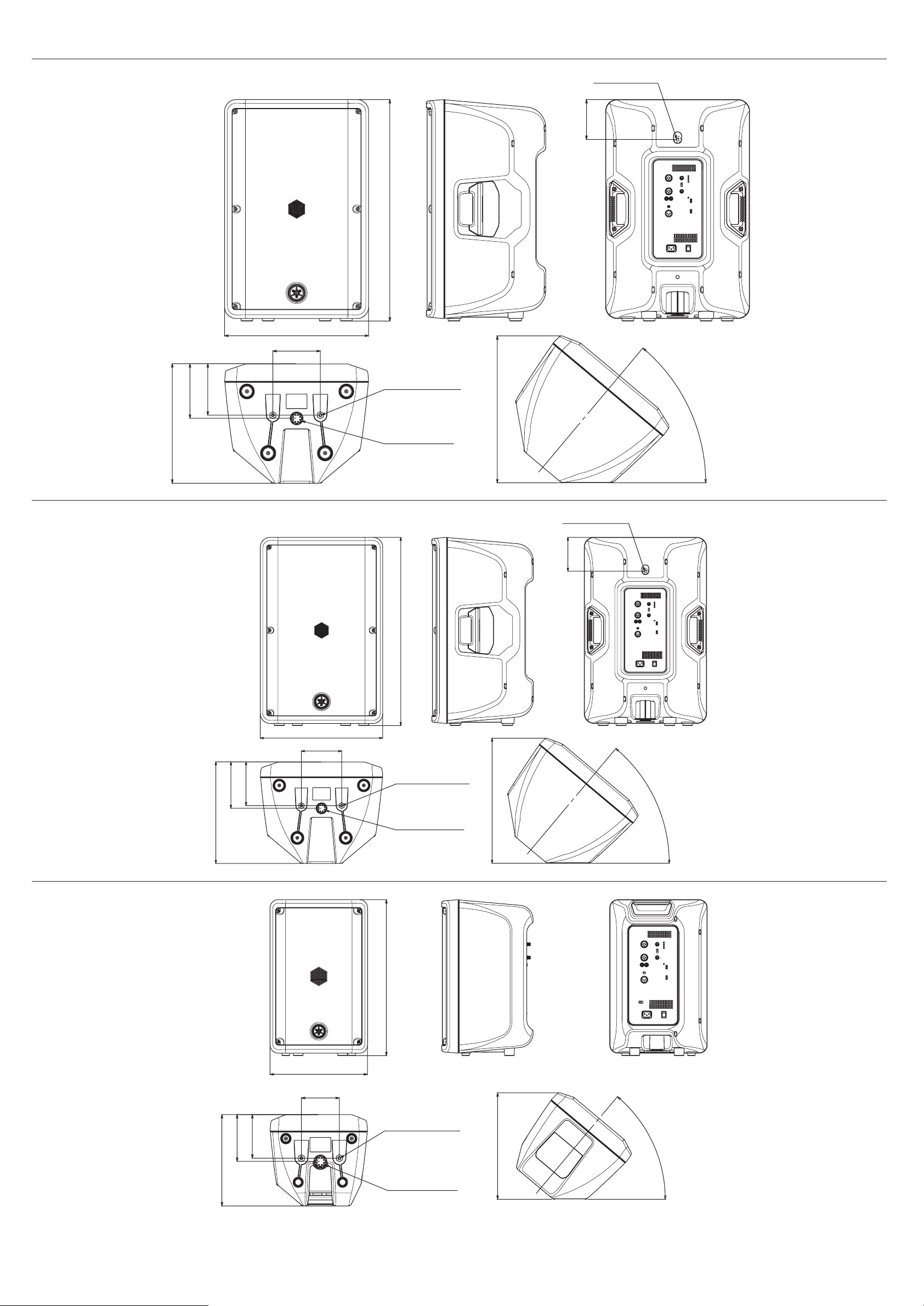
Dimensions
DBR15
173
163
M8 depth 17mm
126
700
455
150
2-M8 depth 17mm
50°
464
DBR12
378
For pole φ35mm
Unit: mm
M8 depth 17mm
102
601
376
150
DBR10
348
162
152
2-M8 depth 17mm
50°
408
For pole φ35mm
Unit: mm
493
308
120
289
148
138
2-M8 depth 17mm
For pole φ35mm
336
50°
Unit: mm
C.S.G., PA Development Division
© 2014 Yamaha Corporation
Published 07/2014 发行 KSZC*.*-01A0
Printed in Indonesia
 Loading...