

Page 1

Reference Booklet
Referenzhandbuch
Guide de référence
Manual de referencia
Page 2

Table of Contents (English)
Inhalt (Deutsch)
Voice List ..............................................................................3
Demo Songs.........................................................................9
Drum/key Assignment List..................................................10
Style List .............................................................................12
Vocal Harmony Type List (CVP-109/107/700) .......................13
Parameter Chart .................................................................13
Fingering Chart...................................................................15
MIDI Data Format ...............................................................16
MIDI Implementation Chart.................................................38
CVP-103: Assembly ...........................................................40
CVP-105: Assembly ...........................................................46
CVP-700: Assembly ...........................................................52
CVP-109/107: Assembly ....................................................60
Specifications .....................................................................67
Table des matières (Français)
Liste des voix........................................................................3
Morceaux de démo...............................................................9
Liste d’assignation instrument de batterie/touche
du clavier......................................................................10
Liste des styles ...................................................................12
Liste des types d’harmonie vocale (CVP-109/107/700) .......... 13
Tableau des paramètres.....................................................13
Tablature ............................................................................15
Format des données MIDI ..................................................16
Feuille d’implantation MIDI .................................................38
CVP-103: Montage .............................................................40
CVP-105: Montage .............................................................46
CVP-700: Montage .............................................................52
CVP-109/107: Montage ......................................................60
Spécifications .....................................................................67
Stimmenverzeichnis .............................................................3
Demo-Songs.........................................................................9
Verzeichnis der Schlagzeugklänge ....................................10
Style-Verzeichnis................................................................12
Liste Stimmharmonietyp (Vocal Harmony Type) (CVP-109/107/700) ..
Parameterübersicht ............................................................13
Akkordliste ..........................................................................15
MIDI-Datenformat ...............................................................16
MIDI-Implementierungstabelle............................................38
CVP-103: Zusammenbau ...................................................40
CVP-105: Zusammenbau ...................................................46
CVP-700: Zusammenbau ...................................................52
CVP-109/107: Zusammenbau ............................................60
Technische Daten...............................................................67
13
Índice (Español)
Lista de voces ......................................................................3
Canciones de demostración .................................................9
Lista de asignaciones de teclas/batería .............................10
Lista de estilos....................................................................12
Lista de tipos Vocal Harmony (CVP-109/107/700)................... 13
Gráfica de parámetros........................................................13
Gráfica de digitado .............................................................15
Formato de datos MIDI.......................................................16
Gráfico de puesta en práctica de MIDI ...............................38
CVP-103: Montaje ..............................................................40
CVP-105: Montaje ..............................................................46
CVP-700: Montaje ..............................................................52
CVP-109/107: Montaje .......................................................60
Especificationes..................................................................67
2
CVP-109/107/105/103/700
Page 3
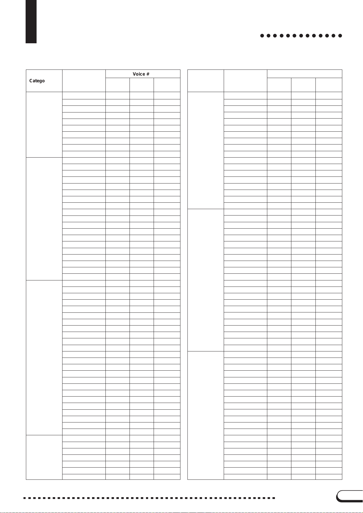
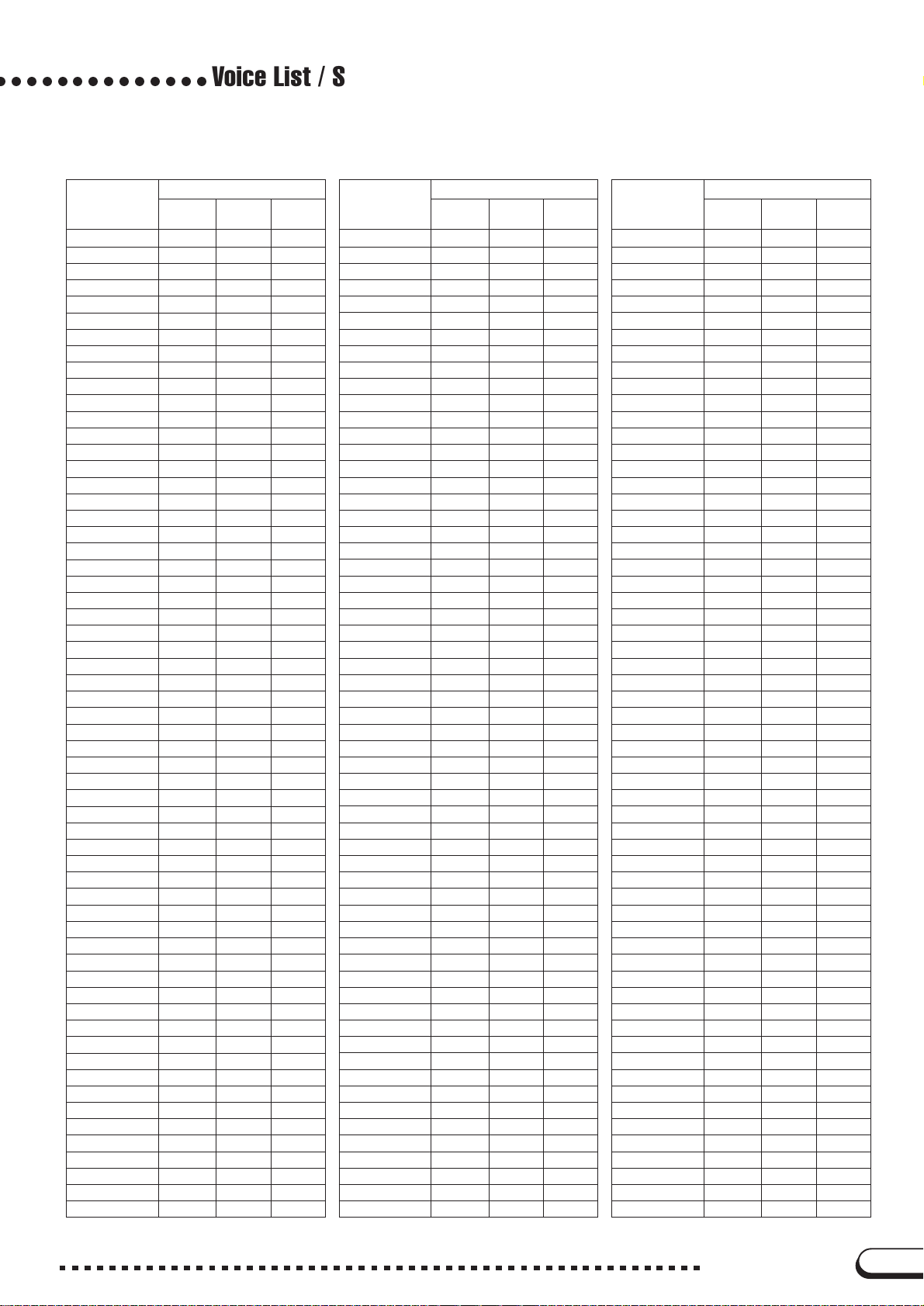
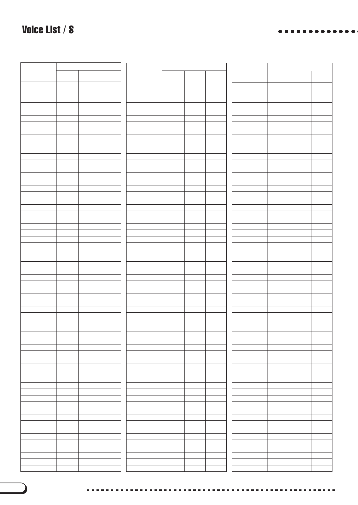
Voice List / Stimmenverzeichnis /
Liste des voix / Lista de voces
CVP-109/107/700
Voice #
Category Voice Name
MSB # LSB #
Piano Grand Piano 0 112 0
Bright Piano 0 112 1
Mellow Piano 0 114 0
Rock Piano 0 113 1
Midi Grand 0 115 2
Harpsichord1 0 112 6
Harpsichord2 0 113 6
Grand Harpsi 0 115 6
Honky Tonk 0 112 3
NewAgePiano 0 118 2
E.Piano Stage EP 1 0 112 4
Galaxy EP 0 118 5
New Tines 0 113 5
Funk EP 0 113 4
DX EP Modern 0 115 5
Vintage EP 0 115 4
CP80 0 116 2
Tremolo EP 0 118 4
Hyper Tines 0 117 5
Clavi. 0 112 7
DX EP 0 112 5
Venus EP 0 116 5
Dream EP 0 114 5
Stage EP 2 0 117 4
Wah Clavi. 0 113 7
DX treme 0 113 92
Funky Clavi. 0 114 7
Galaxian EP 0 113 100
DX-EP & Str. 0 118 88
Guitar Spanish Gtr. 0 113 24
12Str.Guitar 0 115 25
Solid Guitar 0 115 27
Bright Clean 0 113 27
Solid Chord 0 117 27
Jazz Guitar1 0 113 26
Mute Guitar 0 112 28
Banjo 0 112 105
HawaiianGtr. 0 114 26
Crunch Gtr 0 113 30
Smooth Nylon 0 114 24
Elec12string 0 126 27
Folk Guitar1 0 116 25
60’s Clean 0 124 27
Clean Guitar 0 112 27
Jazz Guitar2 0 112 26
OctaveGuitar 0 115 26
Mandolin 0 114 25
Pedal Steel 0 114 27
Feedback Gtr 0 113 29
Gut Guitar 0 112 24
Folk Guitar2 0 112 25
StackCrunch 0 114 30
Dist. Guitar 0 112 30
Synth Golden Age 0 115 88
Insomnia 0 113 94
Wave 2010 0 114 95
NewAge Pad 0 113 88
Fire Wire 0 113 81
Wire Lead 0 114 81
Blaster 0 112 87
Program
Change #
○○○○○○○○○○○○○
Voice #
Category Voice Name
MSB # LSB #
Synth Square Lead 0 112 80
Analogon 0 115 81
Funky Lead 0 116 81
Cyber Pad 0 113 99
Choir Pad 0 112 91
Atmosphere 0 112 99
Brass Pad 0 112 90
Warm Pad 0 112 89
Saw. Lead 0 112 81
Equinox 0 112 94
Stardust 0 112 96
Millenium 0 114 88
Template 0 113 95
Loch Ness 0 113 93
Strings Pad 0 112 51
Wave 2001 0 112 95
Harp Pad 0 112 88
DX Pad 0 112 92
Organ Pipe Organ 0 112 19
Chapel Org.1 0 115 19
Chapel Org.2 0 116 19
Accordion1 0 112 21
Small Accrd. 0 113 21
Rotor Organ 0 112 18
Jazz Organ 1 0 114 17
Rock Organ 0 116 18
Elec. Organ 0 113 16
Organ Flutes 0 116 16
Class. Organ 0 113 19
Chapel Org.3 0 114 19
Tango Accrd. 0 112 23
Accordion2 0 114 21
Tutti Accord 0 115 21
Rotary Drive 0 115 18
Jazz Organ 2 0 117 16
Jazz Organ 3 0 115 16
Perc. Organ 0 115 17
Full Rocker 0 114 18
Theatre Org. 0 114 16
60’s Organ 0 113 17
Strings / Choir Strings 0 118 48
Orch.Str.1 0 115 48
ClassicalStr 0 114 48
Popular Str 0 116 48
Vivaldi Str 0 116 49
Violin 0 112 40
Sweet Cello 0 113 42
Choir 0 112 52
Air Choir 0 112 54
Pizzicato 0 112 45
Orch.Str.2 0 117 48
ChamberStr 0 113 48
Strings Slow 0 113 49
Str.Quartet 0 113 40
Fiddle 0 112 110
Cello 0 114 42
Choir Oohs 0 112 53
Choir Slow 0 113 52
Harp 0 112 46
OrchestraHit 0 112 55
Program
Change #
CVP-109/107/105/103/700
3
Page 4
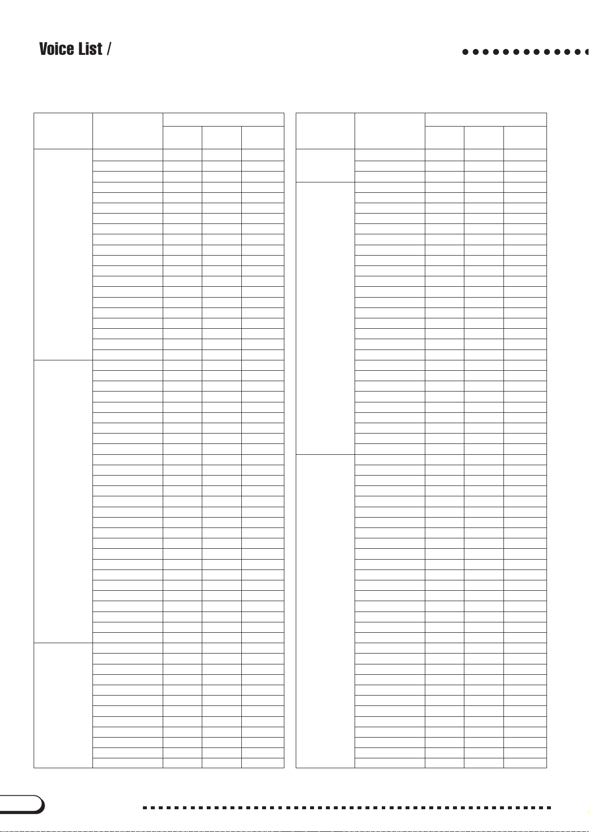
Voice List / Stimmenverzeichnis /Liste des voix / Lista de voces
CVP-109/107/700
Voice #
Category Voice Name
MSB # LSB #
Brass SweetTrumpet 0 115 56
Trombone 0 114 57
MuteTrumpet1 0 113 59
Soft Trumpet 0 114 56
Brass Band 0 118 57
BrassSection 0 112 61
Mellow Brass 0 123 61
BigBnd Brass 0 115 61
Soft Brass 0 116 61
Analog Brass 0 112 63
Solo Trumpet 0 112 56
Trb.Section 0 113 57
MuteTrumpet2 0 112 59
Flugel Horn 0 113 56
Tuba 0 113 58
Big Brass 0 114 61
Bright Brass 0 117 61
French Horn 0 112 60
Ballroom Brs 0 114 59
Synth Brass 0 112 62
Sax / Flute Sweet Tenor 0 113 66
Sweet Flute 0 115 73
Sweet Clari. 0 113 71
Sweet Alto 0 116 65
Growl Sax 0 114 66
Soprano Sax 0 112 64
Pan Flute 1 0 113 75
Modern Harp 0 113 22
Sax Section 0 114 65
WindEnsemble 0 113 73
Breath Tenor 0 115 66
Classical Fl 0 116 73
Clarinet 0 112 71
Breath Alto 0 115 65
Baritone Sax 0 113 67
Oboe 0 112 68
Piccolo 0 113 72
Blues Harm. 0 114 22
Bassoon 0 113 70
Whistle 0 112 78
Tenor Sax 0 116 66
Flute 0 112 73
Alto Sax 0 112 65
English Horn 0 112 69
Recorder 0 113 74
Harmonica 0 112 22
Pan Flute 2 0 112 75
Bass Acous.Bass 1 0 112 32
Elec. Bass 0 113 33
Finger Bass 0 114 33
E. Bass Slap 0 112 33
Pick Bass 0 112 34
FretlessBass 0 112 35
Slap Bass 0 112 36
Synth Bass 1 0 112 38
Analog Bass 0 113 39
Bass&Cymbal 0 114 32
Acous.Bass 2 0 113 32
Bert’s Bass 0 113 34
Program
Change #
Category Voice Name
MSB # LSB #
Bass Synth Bass 2 0 112 39
Hi Q Bass 0 114 38
Synth Bass 3 0 113 38
Percussion Vibes 0 112 11
Marimba 0 112 12
Music Box 0 113 10
Steel Drums 0 112 114
Celesta 0 113 8
Jazz Vibes 0 113 11
Xylophone 0 112 13
Glockenspiel 0 113 9
TubularBells 0 112 14
Timpani 0 112 47
Xylomarimba 0 113 12
Dulcimer 0 112 15
Kalimba 0 112 108
Standard Kit 127 0 0
Standard2Kit 127 0 1
Hit Kit 127 0 4
Room Kit 127 0 8
Rock Kit 127 0 16
Electro Kit 127 0 24
Analog Kit 127 0 25
Dance Kit 127 0 27
Jazz Kit 127 0 32
Brush Kit 127 0 40
Classic Kit 127 0 48
SFX1 Kit 126 0 0
SFX2 Kit 126 0 1
Ensemble 1 Oct. Piano 0 113 3
2 Oct. Piano 0 114 3
Piano & Str 0 118 1
Piano Heaven 0 114 100
Piano&Choir 0 118 0
Orchestral 1 0 117 49
Orchestral 2 0 118 49
Orchestral 3 0 118 68
Orchestral 4 0 116 68
Orchestral 5 0 117 68
Baroque 0 118 6
Flute&Mallet 0 118 73
Guitar&Flute 0 118 24
Guitar&Str 0 115 99
TwelveString 0 114 99
Hallelujah 0 113 53
Evensong 1 0 118 53
Evensong 2 0 118 52
X’mas Organ 0 118 19
Sunrise Pad 0 116 100
Brass&Sax 1 0 118 65
Brass&Sax 2 0 118 66
Moon Sax 1 0 117 71
Moon Sax 2 0 118 71
Trump.&Clari 0 118 56
Brass&Lyra 0 118 63
Flute&Lyra 0 118 72
ElectricJazz 0 116 26
Galaxy Choir 0 117 100
Heaven Stack 0 115 100
○○○○○○○○○○○○○
Voice #
Program
Change #
4
CVP-109/107/105/103/700
Page 5
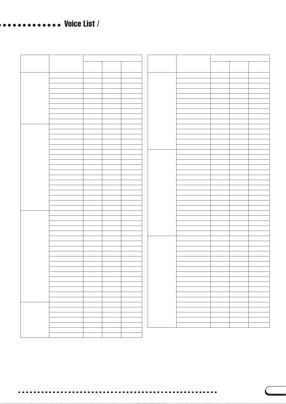
Voice List / Stimmenverzeichnis /Liste des voix / Lista de voces
CVP-105/103
Voice #
Category Voice Name
MSB # LSB #
Piano Grand Piano 0 112 0
Bright Piano 0 112 1
Mellow Piano 0 114 0
Rock Piano 0 113 1
Midi Grand 0 115 2
Harpsichord1 0 112 6
Harpsichord2 0 113 6
Grand Harpsi 0 115 6
Honky Tonk 0 112 3
NewAge Piano 0 118 2
E.Piano Stage EP 1 0 112 4
Galaxy EP 0 118 5
New Tines 0 113 5
Funk EP 0 113 4
DX EP Modern 0 115 5
CP80 0 116 2
Tremolo EP 0 118 4
Hyper Tines 0 117 5
Venus EP 0 116 5
Clavi. 0 112 7
Dream EP 0 114 5
Stage EP 2 0 117 4
Wah Clavi. 0 113 7
DX treme 0 113 92
Funky Clavi. 0 114 7
Galaxian EP 0 113 100
DX-EP & Str. 0 118 88
Guitar Spanish Gtr. 0 113 24
12Str.Guitar 0 115 25
Solid Guitar 0 115 27
Bright Clean 0 113 27
Clean Guitar 0 112 27
Jazz Guitar1 0 113 26
Mute Guitar 0 112 28
Banjo 0 112 105
HawaiianGtr. 0 114 26
Dist. Guitar 0 112 30
Smooth Nylon 0 114 24
Elec12string 0 126 27
Folk Guitar1 0 116 25
Jazz Guitar2 0 112 26
OctaveGuitar 0 115 26
Gut Guitar 0 112 24
Folk Guitar2 0 112 25
Pedal Steel 0 114 27
Synth Golden Age 0 115 88
Insomnia 0 113 94
Wave 2010 0 114 95
NewAge Pad 0 113 88
Fire Wire 0 113 81
Wire Lead 0 114 81
Blaster 0 112 87
Program
Change #
Voice #
Category Voice Name
MSB # LSB #
Synth Square Lead 0 112 80
Analogon 0 115 81
Saw. Lead 0 112 81
Cyber Pad 0 113 99
Choir Pad 0 112 91
Atmosphere 0 112 99
Brass Pad 0 112 90
Warm Pad 0 112 89
Equinox 0 112 94
Stardust 0 112 96
Millenium 0 114 88
Strings Pad 0 112 51
Wave 2001 0 112 95
Harp Pad 0 112 88
DX Pad 0 112 92
Organ Pipe Organ 0 112 19
ChapelOrgan1 0 115 19
ChapelOrgan2 0 116 19
Accordion 0 112 21
Tutti Accord 0 115 21
Rotor Organ 0 112 18
Jazz Organ 1 0 114 17
Rock Organ 0 116 18
Elec. Organ 0 113 16
Jazz Organ 2 0 117 16
Class. Organ 0 113 19
ChapelOrgan3 0 114 19
Tango Accrd. 0 112 23
Jazz Organ 3 0 115 16
Perc. Organ 0 115 17
Theatre Org. 0 114 16
60’s Organ 0 113 17
Strings / Choir OrchStrings1 0 115 48
ClassicalStr 0 114 48
Popular Str 0 116 48
Vivaldi Str 0 116 49
Chamber Str 0 113 48
Violin 0 112 40
Cello 0 114 42
Choir 0 112 52
Air Choir 0 112 54
Pizzicato 0 112 45
OrchStrings2 0 117 48
Strings Slow 0 113 49
Str.Quartet 0 113 40
Fiddle 0 112 110
Choir Oohs 0 112 53
Choir Slow 0 113 52
Harp 0 112 46
OrchestraHit 0 112 55
Program
Change #
CVP-109/107/105/103/700
5
Page 6
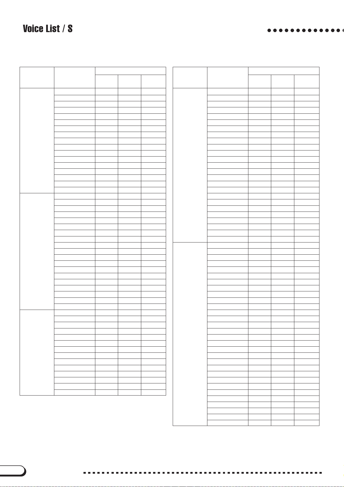
Voice List / Stimmenverzeichnis /Liste des voix / Lista de voces
CVP-105/103
○○○○○○○○○○○○○○
Voice #
Category Voice Name
MSB # LSB #
Brass SweetTrumpet 0 115 56
Trombone 0 114 57
MuteTrumpet1 0 113 59
Soft Trumpet 0 114 56
Brass Band 0 118 57
BrassSection 0 112 61
Mellow Brass 0 123 61
Big Brass 0 114 61
Analog Brass 0 112 63
Synth Brass 0 112 62
Solo Trumpet 0 112 56
Trb.Section 0 113 57
MuteTrumpet2 0 112 59
Flugel Horn 0 113 56
Tuba 0 113 58
French Horn 0 112 60
BallroomBrs 0 114 59
Sax / Flute Breath Tenor 0 115 66
Flute 0 112 73
Clarinet 0 112 71
Breath Alto 0 115 65
Baritone Sax 0 113 67
Soprano Sax 0 112 64
Pan Flute 1 0 113 75
Harmonica 0 112 22
Sax Section 0 114 65
WindEnsemble 0 113 73
Tenor Sax 0 116 66
Alto Sax 0 112 65
Oboe 0 112 68
Piccolo 0 113 72
Bassoon 0 113 70
Whistle 0 112 78
English Horn 0 112 69
Recorder 0 113 74
Pan Flute 2 0 112 75
Bass Acous.Bass 0 112 32
Elec. Bass 0 113 33
Finger Bass 0 114 33
E. Bass Slap 0 112 33
Pick Bass 0 112 34
FretlessBass 0 112 35
Slap Bass 0 112 36
Synth Bass 1 0 112 38
Analog Bass 0 113 39
Bass&Cymbal 0 114 32
Bert’s Bass 0 113 34
Synth Bass 2 0 112 39
Hi Q Bass 0 114 38
Synth Bass 3 0 113 38
Program
Change #
Voice #
Category Voice Name
MSB # LSB #
Percussion Vibes 0 112 11
Marimba 0 112 12
Music Box 0 113 10
Steel Drums 0 112 114
Celesta 0 113 8
Jazz Vibes 0 113 11
Xylophone 0 112 13
Glockenspiel 0 113 9
TubularBells 0 112 14
Timpani 0 112 47
Xylomarimba 0 113 12
Dulcimer 0 112 15
Kalimba 0 112 108
Standard Kit 127 0 0
Standard2Kit 127 0 1
Room Kit 127 0 8
Rock Kit 127 0 16
Electro Kit 127 0 24
Analog Kit 127 0 25
Dance Kit 127 0 27
Jazz Kit 127 0 32
Brush Kit 127 0 40
Classic Kit 127 0 48
SFX1 Kit 126 0 0
SFX2 Kit 126 0 1
Ensemble 1 Oct. Piano 0 113 3
2 Oct. Piano 0 114 3
Piano & Str 0 118 1
Piano Heaven 0 114 100
Piano&Choir 0 118 0
Orchestral 1 0 117 49
Orchestral 2 0 118 49
Orchestral 3 0 118 68
Orchestral 4 0 116 68
Orchestral 5 0 117 68
Baroque 0 118 6
Flute&Mallet 0 118 73
Guitar&Flute 0 118 24
Guitar&Str 0 115 99
TwelveString 0 114 99
Hallelujah 0 113 53
Evensong 1 0 118 53
Evensong 2 0 118 52
X’mas Organ 0 118 19
Sunrise Pad 0 116 100
Brass&Sax 1 0 118 65
Brass&Sax 2 0 118 66
Moonsax 1 0 117 71
Moonsax 2 0 118 71
Trump.&Clari 0 118 56
Brass&Lyra 0 118 63
Flute&Lyra 0 118 72
ElectricJazz 0 116 26
GalaxyChoir 0 117 100
Heaven Stack 0 115 100
Program
Change #
6
CVP-109/107/105/103/700
Page 7
○ ○○○○○○○○○○○○○
XG
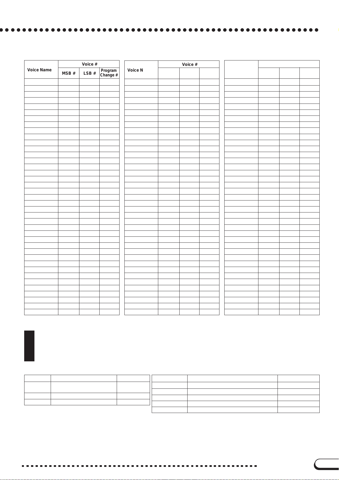
Voice List / Stimmenverzeichnis /Liste des voix / Lista de voces
Voice #
Voice Name
GrandPno 0 0 0
GrndPnoK 0 1 0
MelloGrP 0 18 0
PianoStr 0 40 0
Dream 0 41 0
BritePno 0 0 1
BritPnoK 0 1 1
El.Grand 0 0 2
ElGrPnoK 0 1 2
Det.CP80 0 32 2
LayerCP1 0 40 2
LayerCP2 0 41 2
HnkyTonk 0 0 3
HnkyTnkK 0 1 3
E.Piano1 0 0 4
El.Pno1K 0 1 4
MelloEP1 0 18 4
Chor.EP1 0 32 4
HardEl.P 0 40 4
VX El.P1 0 45 4
60sEl.P1 0 64 4
E.Piano2 0 0 5
El.Pno2K 0 1 5
Chor.EP2 0 32 5
DX Hard 0 33 5
DXLegend 0 34 5
DX Phase 0 40 5
DX+Analg 0 41 5
DXKotoEP 0 42 5
VX El.P2 0 45 5
Harpsi. 0 0 6
Harpsi.K 0 1 6
Harpsi.2 0 25 6
Harpsi.3 0 35 6
Clavi 0 0 7
Clavi K 0 1 7
ClaviWah 0 27 7
PulseClv 0 64 7
PierceCl 0 65 7
Celesta 0 0 8
Glocken 0 0 9
MusicBox 0 0 10
Orgel 0 64 10
Vibes 0 0 11
Vibes K 0 1 11
HardVibe 0 45 11
Marimba 0 0 12
MarimbaK 0 1 12
SineMrmb 0 64 12
Balimba 0 97 12
Log Drum 0 98 12
Xylophon 0 0 13
TubulBel 0 0 14
ChrchBel 0 96 14
Carillon 0 97 14
Dulcimer 0 0 15
Dulcimr2 0 35 15
Cimbalom 0 96 15
Santur 0 9 7 15
DrawOrgn 0 0 16
MSB # LSB #
Program
Change #
Voice #
Voice Name
DetDrwOr 0 32 16
60sDrOr1 0 33 16
60sDrOr2 0 34 16
70sDrOr1 0 35 16
DrawOrg2 0 36 16
60sDrOr3 0 37 16
EvenBar 0 38 16
16+2’2/3 0 40 16
Organ Ba 0 64 16
70sDrOr2 0 65 16
CheezOrg 0 66 16
DrawOrg3 0 67 16
PercOrgn 0 0 17
70sPcOr1 0 24 17
DetPrcOr 0 32 17
Lite Org 0 33 17
PercOrg2 0 37 17
RockOrgn 0 0 18
RotaryOr 0 64 18
SloRotar 0 65 18
FstRotar 0 66 18
ChrchOrg 0 0 19
ChurOrg3 0 32 19
ChurOrg2 0 35 19
NotreDam 0 40 19
OrgFlute 0 64 19
TrmOrgFl 0 65 19
ReedOrgn 0 0 20
Puff Org 0 40 20
Acordion 0 0 21
AccordIt 0 32 21
Harmnica 0 0 22
Harmo. 2 0 32 22
TangoAcd 0 0 23
TngoAcd2 0 64 23
NylonGtr 0 0 24
NylonGt2 0 16 24
NylonGt3 0 25 24
VelGtHrm 0 43 24
Ukulele 0 96 24
SteelGtr 0 0 25
SteelGt2 0 16 25
12StrGtr 0 35 25
Nyln&Stl 0 40 25
Stl&Body 0 41 25
Mandolin 0 96 25
Jazz Gtr 0 0 26
MelloGtr 0 18 26
Jazz Amp 0 32 26
CleanGtr 0 0 27
ChorusGt 0 32 27
Mute Gtr 0 0 28
FunkGtr1 0 40 28
MuteStlG 0 41 28
FunkGtr2 0 43 28
Jazz Man 0 45 28
Ovrdrive 0 0 29
Gt.Pinch 0 43 29
Dist.Gtr 0 0 30
FeedbkGt 0 40 30
MSB # LSB #
Program
Change #
Voice #
Voice Name
FeedbGt2 0 41 30
GtrHarmo 0 0 31
GtFeedbk 0 65 31
GtrHrmo2 0 66 31
Aco.Bass 0 0 32
JazzRthm 0 40 32
VXUprght 0 45 32
FngrBass 0 0 33
FingrDrk 0 18 33
FlangeBa 0 27 33
Ba&DstEG 0 40 33
FngrSlap 0 43 33
FngBass2 0 45 33
Mod.Bass 0 65 33
PickBass 0 0 34
MutePkBa 0 28 34
Fretless 0 0 35
Fretles2 0 32 35
Fretles3 0 33 35
Fretles4 0 34 35
SynFretl 0 96 35
SmthFrt1 0 97 35
SlapBas1 0 0 36
ResoSlap 0 27 36
PunchThm 0 32 36
SlapBas2 0 0 37
VeloSlap 0 43 37
SynBass1 0 0 38
SynBa1Dk 0 18 38
FastResB 0 20 38
AcidBass 0 24 38
Clv Bass 0 35 38
TechnoBa 0 40 38
Orbiter 0 64 38
Sqr.Bass 0 65 38
RubberBa 0 66 38
Hammer 0 96 38
SynBass2 0 0 39
MelloSBa 0 6 39
Seq Bass 0 12 39
ClkSynBa 0 18 39
SynBa2Dk 0 19 39
SmthSynB 0 32 39
ModulrBa 0 40 39
DX Bass 0 41 39
X WireBa 0 64 39
Violin 0 0 40
Slow Vln 0 8 40
Viola 0 0 41
Cello 0 0 42
Contrabs 0 0 43
Trem.Str 0 0 44
SlwTrStr 0 8 44
Susp. Str 0 40 44
Pizz.Str 0 0 45
Harp 0 0 46
YangChin 0 40 46
Timpani 0 0 47
Strings1 0 0 48
S.Strngs 0 3 48
MSB # LSB #
Program
Change #
CVP-109/107/105/103/700
7
Page 8
Voice List / Stimmenverzeichnis /Liste des voix / Lista de voces
XG
Voice #
Voice Name
Slow Str 0 8 48
Arco Str 0 24 48
60sStrng 0 35 48
Orchestr 0 40 48
Orchstr2 0 41 48
TremOrch 0 42 48
Velo.Str 0 45 48
Strings2 0 0 49
S.SlwStr 0 3 49
LegatoSt 0 8 49
Warm Str 0 40 49
Kingdom 0 41 49
70s Str 0 64 49
Strings3 0 65 49
Syn Str1 0 0 50
Reso Str 0 27 50
Syn Str4 0 64 50
Syn Str5 0 65 50
Syn Str2 0 0 51
ChoirAah 0 0 52
S.Choir 0 3 52
Ch.Aahs2 0 16 52
MelChoir 0 32 52
ChoirStr 0 40 52
VoiceOoh 0 0 53
SynVoice 0 0 54
SyVoice2 0 40 54
Choral 0 41 54
AnaVoice 0 64 54
Orch.Hit 0 0 55
OrchHit2 0 35 55
Impact 0 64 55
Trumpet 0 0 56
Trumpet2 0 16 56
BriteTrp 0 17 56
Warm Trp 0 32 56
Trombone 0 0 57
Trmbone2 0 18 57
Tuba 0 0 58
Tuba 2 0 16 58
Mute Trp 0 0 59
Fr.Horn 0 0 60
FrHrSolo 0 6 60
FrHorn 2 0 32 60
HornOrch 0 37 60
BrssSect 0 0 61
Tp&TbSec 0 35 61
BrssSec2 0 40 61
HiBrass 0 41 61
MelloBrs 0 42 61
SynBrss1 0 0 62
Quack Br 0 12 62
RezSynBr 0 20 62
PolyBrss 0 24 62
SynBrss3 0 27 62
JumpBrss 0 32 62
AnVelBr1 0 45 62
AnVelBr2 0 64 62
SynBrss2 0 0 63
Soft Brs 0 18 63
SynBrss4 0 40 63
MSB # LSB #
Program
Change #
Voice Name
ChoirBrs 0 41 63
VelBrss2 0 45 63
AnaBrss2 0 64 63
SprnoSax 0 0 64
Alto Sax 0 0 65
Sax Sect 0 40 65
HyprAlto 0 43 65
TenorSax 0 0 66
BrthTnSx 0 40 66
SoftTenr 0 41 66
TnrSax 2 0 64 66
Bari.Sax 0 0 67
Oboe 0 0 68
Eng.Horn 0 0 69
Bassoon 0 0 70
Clarinet 0 0 71
Piccolo 0 0 72
Flute 0 0 73
Recorder 0 0 74
PanFlute 0 0 75
Bottle 0 0 76
Shakhchi 0 0 77
Whistle 0 0 78
Ocarina 0 0 79
SquareLd 0 0 80
SquarLd2 0 6 80
LMSquare 0 8 80
Hollow 0 18 80
Shroud 0 19 80
Mellow 0 64 80
SoloSine 0 65 80
SineLead 0 66 80
Saw Lead 0 0 81
Saw Ld 2 0 6 81
ThickSaw 0 8 81
Dyna Saw 0 18 81
Digi Saw 0 19 81
Big Lead 0 20 81
HeavySyn 0 24 81
WaspySyn 0 25 81
PulseSaw 0 4 0 81
Dr. Lead 0 41 81
VeloLead 0 45 81
Seq Ana. 0 96 81
CaliopLd 0 0 82
PureLead 0 65 82
Chiff Ld 0 0 83
Rubby 0 64 83
CharanLd 0 0 84
DistLead 0 64 84
WireLead 0 65 84
Voice Ld 0 0 85
SynthAah 0 24 85
Vox Lead 0 64 85
Fifth Ld 0 0 86
Big Five 0 35 86
Bass&Ld 0 0 87
Big&Low 0 16 87
Fat&Prky 0 64 87
Soft Wrl 0 65 87
NewAgePd 0 0 88
MSB # LSB #
Voice #
Program
Change #
Voice Name
Fantasy 0 64 88
Warm Pad 0 0 89
ThickPad 0 16 89
Soft Pad 0 17 89
Sine Pad 0 18 89
Horn Pad 0 64 89
RotarStr 0 65 89
PolySyPd 0 0 90
PolyPd80 0 64 90
ClickPad 0 65 90
Ana. Pad 0 66 90
SquarPad 0 6 7 90
ChoirPad 0 0 91
Heaven 0 64 91
Itopia 0 66 91
CC Pad 0 67 91
BowedPad 0 0 92
Glacier 0 64 92
GlassPad 0 65 92
MetalPad 0 0 93
Tine Pad 0 64 93
Pan Pad 0 65 93
Halo Pad 0 0 94
SweepPad 0 0 95
Shwimmer 0 20 95
Converge 0 27 95
PolarPad 0 64 95
Celstial 0 66 95
Rain 0 0 96
ClaviPad 0 45 96
HrmoRain 0 64 96
AfrcnWnd 0 65 96
Carib 0 66 96
SoundTrk 0 0 97
Prologue 0 27 97
Ancestrl 0 64 97
Crystal 0 0 98
SynDrCmp 0 12 98
Popcorn 0 14 98
TinyBell 0 18 98
RndGlock 0 35 98
GlockChi 0 40 98
ClearBel 0 41 98
ChorBell 0 42 98
SynMalet 0 64 98
SftCryst 0 65 98
LoudGlok 0 66 98
ChrstBel 0 67 98
VibeBell 0 68 98
DigiBell 0 69 98
AirBells 0 70 98
BellHarp 0 71 98
Gamelmba 0 72 98
Atmosphr 0 0 99
WarmAtms 0 18 99
HollwRls 0 19 99
Nylon EP 0 40 99
NylnHarp 0 64 99
Harp Vox 0 65 99
AtmosPad 0 66 99
Planet 0 67 99
○○○○○○○○○○○○○○
Voice #
MSB # LSB #
Program
Change #
8
CVP-109/107/105/103/700
Page 9
○ ○○○○○○○○○○○○○○○○○○○○○○○○○○○○○○○○○○○○○○○○○○○○○○○○○○○○○○○
XG
Voice #
Voice Name
Bright 0 0 100
FantaBel 0 64 100
Smokey 0 96 100
Goblins 0 0 101
GobSynth 0 64 101
Creeper 0 65 101
Ring Pad 0 66 101
Ritual 0 67 101
ToHeaven 0 68 101
Night 0 70 101
Glisten 0 71 101
BelChoir 0 96 101
Echoes 0 0 102
Echoes 2 0 8 102
Echo Pan 0 14 102
EchoBell 0 64 102
Big Pan 0 65 102
SynPiano 0 66 102
Creation 0 67 102
StarDust 0 68 102
Reso&Pan 0 69 102
Sci-Fi 0 0 103
Starz 0 64 103
Sitar 0 0 104
DetSitar 0 32 104
Sitar 2 0 35 104
Tambra 0 96 104
Tamboura 0 97 104
Banjo 0 0 105
MuteBnjo 0 28 105
Rabab 0 96 105
Gopichnt 0 97 105
Oud 0 98 105
Shamisen 0 0 106
Koto 0 0 107
Taisho-k 0 96 107
Kanoon 0 97 107
Kalimba 0 0 108
Bagpipe 0 0 109
MSB # LSB #
Program
Change #
Voice #
Voice Name
Fiddle 0 0 110
Shanai 0 0 111
Shanai 2 0 64 111
Pungi 0 96 111
Hichriki 0 97 111
TnklBell 0 0 112
Bonang 0 96 112
Altair 0 97 112
Gamelan 0 98 112
S.Gamlan 0 99 112
Rama Cym 0 100 112
AsianBel 0 101 112
Agogo 0 0 113
SteelDrm 0 0 114
GlasPerc 0 97 114
ThaiBell 0 98 114
WoodBlok 0 0 115
Castanet 0 96 115
TaikoDrm 0 0 116
Gr.Cassa 0 96 116
MelodTom 0 0 117
Mel Tom2 0 64 117
Real Tom 0 65 117
Rock Tom 0 66 117
Syn Drum 0 0 118
Ana Tom 0 64 118
ElecPerc 0 65 118
RevCymbl 0 0 119
FretNoiz 0 0 120
BrthNoiz 0 0 121
Seashore 0 0 122
Tweet 0 0 123
Telphone 0 0 124
Helicptr 0 0 125
Applause 0 0 126
Gunshot 0 0 127
CuttngNz 64 0 0
CttngNz2 64 0 1
Str Slap 64 0 3
MSB # LSB #
Program
Change #
Voice Name
Fl.KClik 64 0 16
Shower 64 0 32
Thunder 64 0 33
Wind 64 0 34
Stream 64 0 35
Bubble 64 0 36
Feed 64 0 37
Dog 64 0 48
Horse 64 0 49
Tweet 2 64 0 50
Ghost 64 0 54
Maou 64 0 55
Tel.Dial 64 0 64
DoorSqek 64 0 65
DoorSlam 64 0 66
ScratchC 64 0 67
ScratchS 64 0 68
WindChim 64 0 69
Telphon2 64 0 70
CarEIgnt 64 0 80
CarTSqel 64 0 81
Car Pass 64 0 82
CarCrash 64 0 83
Siren 64 0 84
Train 64 0 85
JetPlane 64 0 86
Starship 64 0 87
Burst 64 0 88
Coaster 64 0 89
Submarin 64 0 90
Laugh 64 0 96
Scream 64 0 97
Punch 64 0 98
Heart 64 0 99
Footstep 64 0 100
MchinGun 64 0 112
LaserGun 64 0 113
Xplosion 64 0 114
Firework 64 0 115
MSB # LSB #
Voice #
Program
Change #
Demo Songs / Demo-Songs /
Morceaux de démo / Canciones de demostración
SONG DEMO
Title Composer
Song 1
Song 3 Beautiful Dreamer S.C.Foster
Song 4 Annie Laurie Traditional
• Some of the demonstration pieces listed above are specially-arranged excerpts from the original compositions listed above.
All other songs are original (©1999 Yamaha Corporation).
• Bei manchen der oben aufgelisteten Demostücke handelt es sich um Auszüge aus den Originalkompositionen mit speziellem Arrangement. Alle anderen Stücke sind eigene Kompositionen (© 1999 Yamaha Corporation).
• Certains des morceaux de démonstration énumérés ci-dessus sont de courts extraits des compositions originales.
Tous les autres morceaux sont des créations originales (© 1999 Yamaha Corporation).
• Alguna de las piezas de demostración arriba listadas son exceptos especialmente preparados de las composiciones
originales de arriba. Todas las otras canciones son originales (© 1999 Yamaha Corporation.)
Klavier Konzert a moll op.16
(Piano Concert a minor op.16)
E.Grieg
VOICE DEMO
Title Composer
PIANO Walzer op.70-1 F.Chopin
SYNTHESIZER Bruyeres C.A.Debussy
ORGAN
PERCUSSION Air de Ballet M.Moszkowski
XG TREPAK from “Nutcracker Suite” op.71a P.I.Tschaikovsky
Choralvorspiele “Ich ruf’ zu dir, Herr Jesus Christ”
J.S.Bach
CVP-109/107/105/103/700
9
Page 10
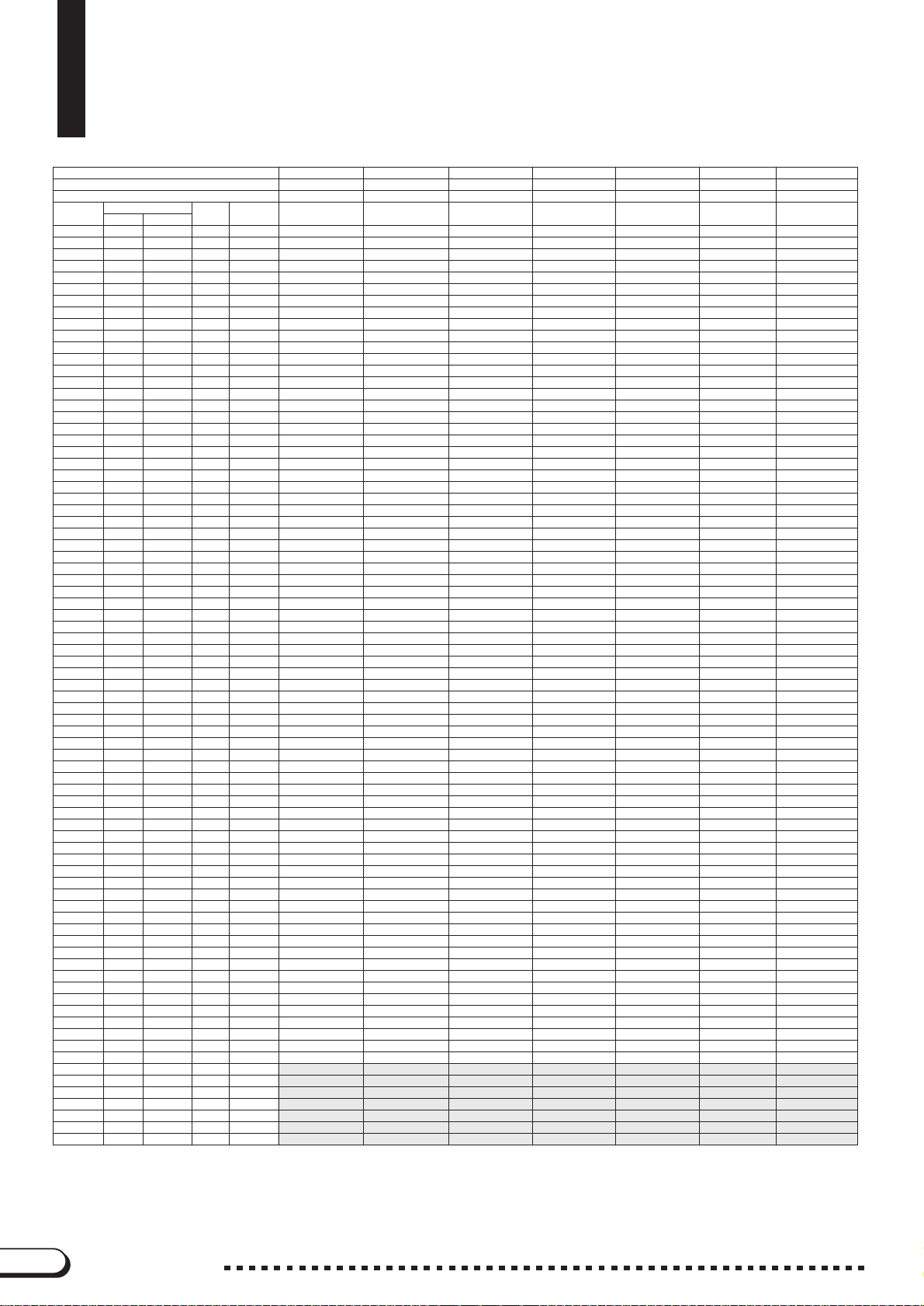
Drum/key Assignment List / Verzeichnis der
Liste d’assignation instrument de batterie/
Lista de asignaciones de teclas/batería
Bank Select MSB 127 127 127 127 127 127 127
Bank Select LSB 0 0 0 0 0 0 0
Program # (1-128) 1 2 4 9 17 25 26
Keyboard MIDI Key Alternate Standard Kit Standard 2 Kit Hit Kit Room Kit Rock Kit Electro Kit Analog Kit
Note Note # Note off assign
C# 113C# -1 3 Surdo Mute Surdo Mute Surdo Mute Surdo Mute Surdo Mute Surdo Mute Surdo Mute
D 1 14 D -1 3 Surdo Open Surdo Open Surdo Open Surdo Open Surdo Open Surdo Open Surdo Open
D# 115D# -1 Hi Q Hi Q Hi Q Hi Q Hi Q Hi Q Hi Q
E 1 16 E -1 Whip Slap Whip Slap Whip Slap Whip Slap Whip Slap Whip Slap Whip Slap
F 1 17 F -1 4 Scratch H Scratch H Scratch H Scratch H Scratch H Scratch H Scratch H
F# 118F# -1 4 Scratch L Scratch L Scratch L Scratch L Scratch L Scratch L Scratch L
G 1 19 G -1 Finger Snap Finger Snap Finger Snap Finger Snap Finger Snap Finger Snap Finger Snap
G# 120G# -1 Click Noise Click Noise Click Noise Click Noise Click Noise Click Noise Click Noise
A 1 21 A -1 Mtrnm Click Mtrnm Click Mtrnm Click Mtrnm Click Mtrnm Click Mtrnm Click Mtrnm Click
A# 122A# -1 Mtrnm Bell Mtrnm Bell Mtrnm Bell Mtrnm Bell Mtrnm Bell Mtrnm Bell Mtrnm Bell
B 1 23 B -1 Seq Click L Seq Click L Seq Click L Seq Click L Seq Click L Seq Click L Seq Click L
C 2 24 C 0 Seq Click H Seq Click H Seq Click H Seq Click H Seq Click H Seq Click H Seq Click H
C# 225C# 0 Brush Tap Brush Tap Brush Tap Brush Tap Brush Tap Brush Tap Brush Tap
D2 26 D0
D# 227D# 0 Brush Slap Brush Slap Brush Slap Brush Slap Brush Slap Brush Slap Brush Slap
E2 28 E0
F2 29 F0
F# 230F# 0 Castanet Castanet Castanet Castanet Castanet Hi Q 2 Hi Q 2
G 2 31 G 0 Snare Soft Snare Soft 2 Snare Electro Snare Soft Snare Noisy SnrSnpyElctr SnareNoisy 4
G# 232G# 0 Sticks Sticks Sticks Sticks Sticks Sticks Sticks
A 2 33 A 0 Kick Soft Kick Soft Kick Tight L Kick Soft Kick Tight 2 Kick 3 Kick Tight 2
A# 234A# 0 OpenRimShot RimShotHShrt Snare Pitched OpenRimShot OpenRimShot OpenRimShot OpenRimShot
B 2 35 B 0 Kick Tight KickTghtShrt Kick Wet Kick Tight Kick 2 Kick Gate KickAnlgShrt
C 3 36 C 1 Kick Kick Short Kick Tight H Kick Kick Gate KckGateHeavy Kick Analog
C# 337C# 1 Side Stick Side Stick Stick Ambient Side Stick Side Stick Side Stick SideStickAn
D 3 38 D 1 Snare Snare Short Snare Ambient Snare Snappy Snare Rock SnareNoisy 2 SnareAnalog
D# 339D# 1 Hand Clap Hand Clap Hand Clap Hand Clap Hand Clap Hand Clap Hand Clap
E 3 40 E 1 Snare Tight SnareTight H Snare Tight 2 SnrTightSnpy SnareRockRim SnareNoisy 3 SnareAnalog2
F 3 41 F 1 Floor Tom L Floor Tom L Hybrid Tom 1 Tom Room 1 Tom Rock 1 TomElectro 1 Tom Analog 1
F# 342F# 1 1 Hi-HatClosed Hi-HatClosed Hi-Hat Closed Light Hi-HatClosed Hi-HatClosed Hi-HatClosed HatCloseAnlg
G 3 43 G 1 Floor Tom H Floor Tom H Hybrid Tom 2 Tom Room 2 Tom Rock 2 TomElectro 2 Tom Analog 2
G# 344G# 1 1 Hi-Hat Pedal Hi-Hat Pedal Hi-Hat Pedal Light Hi-Hat Pedal Hi-Hat Pedal Hi-Hat Pedal HatCloseAn 2
A 3 45 A 1 Low Tom Low Tom Hybrid Tom 3 Tom Room 3 Tom Rock 3 TomElectro 3 Tom Analog 3
A# 346A# 1 1 Hi-Hat Open Hi-Hat Open Hi-Hat Open Light Hi-Hat Open Hi-Hat Open Hi-Hat Open HatOpen Anlg
B 3 47 B 1 Mid Tom L Mid Tom L Hybrid Tom 4 Tom Room 4 Tom Rock 4 TomElectro 4 Tom Analog 4
C 4 48 C 2 Mid Tom H Mid Tom H Hybrid Tom 5 Tom Room 5 Tom Rock 5 TomElectro 5 Tom Analog 5
C# 449C# 2 CrashCymbal1 CrashCymbal1 CrashCymbal1 CrashCymbal1 CrashCymbal1 CrashCymbal1 Crash Analog
D 4 50 D 2 High Tom High Tom Hybrid Tom 6 Tom Room 6 Tom Rock 6 TomElectro 6 Tom Analog 6
D# 451D# 2 RideCymbal 1 RideCymbal 1 RideCymbal 1 RideCymbal 1 RideCymbal 1 RideCymbal 1 RideCymbal 1
E 4 52 E 2 Chinese Cym Chinese Cym Chinese Cym Chinese Cym Chinese Cym Chinese Cym Chinese Cym
F 4 53 F 2 Ride Cym Cup Ride Cym Cup Ride Cym Cup Ride Cym Cup Ride Cym Cup Ride Cym Cup Ride Cym Cup
F# 454F# 2 Tambourine Tambourine Tambourine Light Tambourine Tambourine Tambourine Tambourine
G 4 55 G 2 SplashCymbal SplashCymbal SplashCymbal SplashCymbal SplashCymbal SplashCymbal SplashCymbal
G# 456G# 2 Cowbell Cowbell Cowbell Cowbell Cowbell Cowbell Cowbell Anlg
A 4 57 A 2 CrashCymbal2 CrashCymbal2 CrashCymbal2 CrashCymbal2 CrashCymbal2 CrashCymbal2 CrashCymbal2
A# 458A# 2 Vibraslap Vibraslap Vibraslap Vibraslap Vibraslap Vibraslap Vibraslap
B 4 59 B 2 RideCymbal 2 RideCymbal 2 RideCymbal 2 RideCymbal 2 RideCymbal 2 RideCymbal 2 RideCymbal 2
C 5 60 C 3 Bongo H Bongo H Bongo H Bongo H Bongo H Bongo H Bongo H
C# 561C# 3 Bongo L Bongo L Bongo L Bongo L Bongo L Bongo L Bongo L
D 5 62 D 3 Conga H Mute Conga H Mute Conga H Mute Conga H Mute Conga H Mute Conga H Mute Conga Anlg H
D# 563D# 3 Conga H Open Conga H Open Conga H Open Conga H Open Conga H Open Conga H Open Conga Anlg M
E 5 64 E 3 Conga L Conga L Conga L Conga L Conga L Conga L Conga Anlg L
F 5 65 F 3 Timbale H Timbale H Timbale H Timbale H Timbale H Timbale H Timbale H
F# 566F# 3 Timbale L Timbale L Timbale L Timbale L Timbale L Timbale L Timbale L
G 5 67 G 3 Agogo H Agogo H Agogo H Agogo H Agogo H Agogo H Agogo H
G# 568G# 3 Agogo L Agogo L Agogo L Agogo L Agogo L Agogo L Agogo L
A 5 69 A 3 Cabasa Cabasa Cabasa Cabasa Cabasa Cabasa Cabasa
A# 570A# 3 Maracas Maracas Maracas Maracas Maracas Maracas Maracas 2
B5 71 B3
C6 72 C4
C# 673C# 4 Guiro Short Guiro Short Guiro Short Guiro Short Guiro Short Guiro Short Guiro Short
D6 74 D4
D# 675D# 4 Claves Claves Claves Claves Claves Claves Claves 2
E 6 76 E 4 Wood Block H Wood Block H Wood Block H Wood Block H Wood Block H Wood Block H Wood Block H
F 6 77 F 4 Wood Block L Wood Block L Wood Block L Wood Block L Wood Block L Wood Block L Wood Block L
F# 678F# 4 Cuica Mute Cuica Mute Cuica Mute Cuica Mute Cuica Mute Scratch H 2 Scratch H 2
G 6 79 G 4 Cuica Open Cuica Open Cuica Open Cuica Open Cuica Open Scratch L 2 Scratch L 3
G# 680G# 4 2 TriangleMute TriangleMute TriangleMute TriangleMute TriangleMute TriangleMute TriangleMute
A 6 81 A 4 2 TriangleOpen TriangleOpen TriangleOpen TriangleOpen TriangleOpen TriangleOpen TriangleOpen
A# 682A# 4 Shaker Shaker Shaker Shaker Shaker Shaker Shaker
B 6 83 B 4 Jingle Bells Jingle Bells Jingle Bells Jingle Bells Jingle Bells Jingle Bells Jingle Bells
C 7 84 C 5 Bell Tree Bell Tree Bell Tree Bell Tree Bell Tree Bell Tree Bell Tree
– 85 C# 5
– 86 D 5
– 87 D# 5
– 88 E 5
– 89 F 5
– 90 F# 5
– 91 G 5
• Key Off: Keys marked “O” stop sounding the instant they are released.
• Alternate Assign: Playing any instrument within a numbered group will imme-
diately stop the sound of any other instrument in the same group of the same
number.
O
O
O
O
O
O
Brush Swirl Brush Swirl Brush Swirl Brush Swirl Brush Swirl Brush Swirl Brush Swirl
BrushTapSwrl BrushTapSwrl BrushTapSwrl BrushTapSwrl BrushTapSwrl ReversCymbal ReversCymbal
Snare Roll Snare Roll 2 Snare Roll Snare Roll Snare Roll Snare Roll Snare Roll
SambaWhistlH SambaWhistlH SambaWhistlH SambaWhistlH SambaWhistlH SambaWhistlH SambaWhistlH
SambaWhistlL SambaWhistlL SambaWhistlL SambaWhistlL SambaWhistlL SambaWhistlL SambaWhistlL
Guiro Long Guiro Long Guiro Long Guiro Long Guiro Long Guiro Long Guiro Long
(CVP-109/107/700)
• Key Off: Durch “O” gekennzeichnete Klänge verstummen beim Loslassen
der Taste.
• Alternate Assign: Mit derselben Nummer gekennzeichnete Klänge werden
von demselben Instrument erzeugt und können daher nicht gleichzeitig
produziert werden. Spielt einer dieser Klänge gerade, wird er beim
Anschlagen einer anderen Taste mit derselben “Alternate Assign”-Nummer
stummgeschaltet.
10
CVP-109/107/105/103/700
Page 11
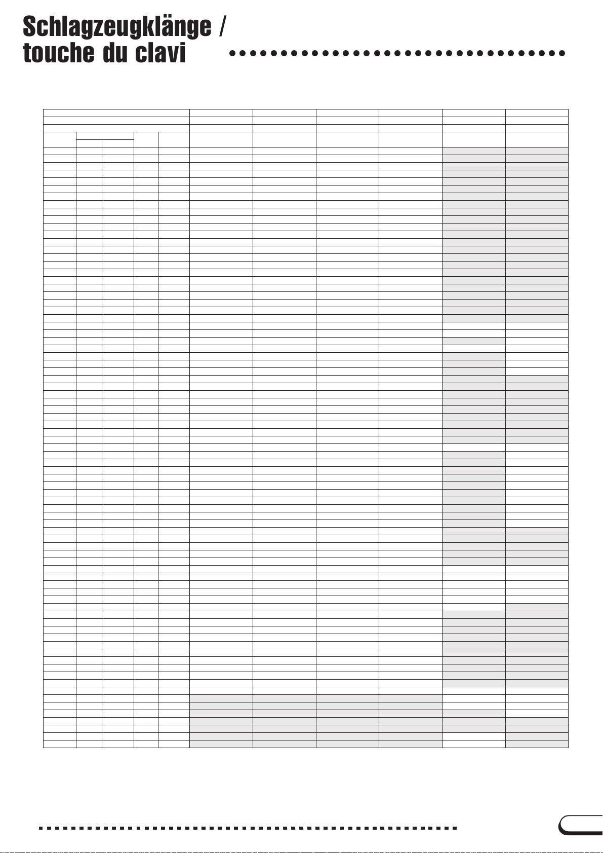
Schlagzeugklänge /
touche du clavier /
○○○○○○○○○○○○○○○○○○○○○○○○○○○○○○○○○
Bank Select MSB 127 127 127 127 126 126
Bank Select LSB 0 0 0 0 0 0
Program # (1-128) 28 33 41 49 1 2
Keyboard MIDI Key Alternate Dance Kit Jazz Kit Brush Kit Symphony Kit SFX Kit 1 SFX Kit 2
Note Note # Note off assign
C# 113C# -1 3 Surdo Mute Surdo Mute Surdo Mute Surdo Mute
D 1 14 D - 1 3 Surdo Open Surdo Open Surdo Open Surdo Open
D# 115D# -1 Hi Q Hi Q Hi Q Hi Q
E 1 16 E -1 Whip Slap Whip Slap Whip Slap Whip Slap
F 1 17 F -1 4 Scratch H Scratch H Scratch H Scratch H
F# 118F# -1 4 Scratch L Scratch L Scratch L Scratch L
G 1 19 G -1 Finger Snap Finger Snap Finger Snap Finger Snap
G# 120G# -1 Click Noise Click Noise Click Noise Click Noise
A 1 21 A -1 Mtrnm Click Mtrnm Click Mtrnm Click Mtrnm Click
A# 122A# -1 Mtrnm Bell Mtrnm Bell Mtrnm Bell Mtrnm Bell
B 1 23 B -1 Seq Click L Seq Click L Seq Click L Seq Click L
C 2 24 C 0 Seq Click H Seq Click H Seq Click H Seq Click H
C# 225C# 0 Brush Tap Brush Tap Brush Tap Brush Tap
D2 26 D0
D# 227D# 0 Brush Slap Brush Slap Brush Slap Brush Slap
E2 28 E0
F2 29 F0
F# 230F# 0 Hi Q 2 Castanet Castanet Castanet
G 2 31 G 0 SnareTechno3 Snare Soft Brush Slap 2 Brush Slap 2
G# 232G# 0 Sticks Sticks Sticks Sticks
A 2 33 A 0 KickTechno Q Kick Soft Kick Soft Kick Soft 2
A# 234A# 0 Rim Gate OpenRimShot OpenRimShot OpenRimShot
B 2 35 B 0 KickTechno L Kick Tight Kick Tight Gran Cassa
C 3 36 C 1 KickTechno 2 Kick Jazz Kick Small GranCassa Mu CuttingNoiz Phone Call
C# 337C# 1 SideStickAn Side Stick Side Stick Side Stick CuttingNoiz2 Door Squeak
D 3 38 D 1 Snare Clap Snare Brush Slap 3 Band Snare Door Slam
D# 339D# 1 Hand Clap Hand Clap Hand Clap Hand Clap String Slap Scratch Cut
E 3 40 E 1 Snare Dry 2 Snare Tight Brush Tap 2 Band Snare 2 Scratch H 3
F 3 41 F 1 Tom Analog 1 Tom Jazz 1 Tom Brush 1 Tom Jazz 1 Wind Chime
F# 342F# 1 1 HiHatClose 3 Hi-HatClosed Hi-HatClosed Hi-HatClosed Telephone 2
G 3 43 G 1 Tom Analog 2 Tom Jazz 2 Tom Brush 2 Tom Jazz 2
G# 344G# 1 1 HatCloseAn 2 Hi-Hat Pedal Hi-Hat Pedal Hi-Hat Pedal
A 3 45 A 1 Tom Analog 3 Tom Jazz 3 Tom Brush 3 Tom Jazz 3
A# 346A# 1 1 HiHat Open 3 Hi-Hat Open Hi-Hat Open Hi-Hat Open
B 3 47 B 1 Tom Analog 4 Tom Jazz 4 Tom Brush 4 Tom Jazz 4
C 4 48 C 2 Tom Analog 5 Tom Jazz 5 Tom Brush 5 Tom Jazz 5
C# 449C# 2 Crash Analog CrashCymbal1 CrashCymbal1 Hand Cymbal
D 4 50 D 2 Tom Analog 6 Tom Jazz 6 Tom Brush 6 Tom Jazz 6
D# 451D# 2 RideCymbal 1 RideCymbal 1 RideCymbal 1 HandCymShort
E 4 52 E 2 Chinese Cym Chinese Cym Chinese Cym Chinese Cym Fl.Key Click Ignition
F 4 53 F 2 Ride Cym Cup Ride Cym Cup Ride Cym Cup Ride Cym Cup Squeal
F# 454F# 2 Tambourine Tambourine Tambourine Tambourine Exhaust
G 4 55 G 2 SplashCymbal SplashCymbal SplashCymbal SplashCymbal Crash
G# 456G# 2 Cowbell Anlg Cowbell Cowbell Cowbell Siren
A 4 57 A 2 CrashCymbal2 CrashCymbal2 CrashCymbal2 HandCymbal 2 Train
A# 458A# 2 Vibraslap Vibraslap Vibraslap Vibraslap Jet Plane
B 4 59 B 2 RideCymbal 2 RideCymbal 2 RideCymbal 2 HandCym2Shrt Starship
C 5 60 C 3 Bongo H Bongo H Bongo H Bongo H Burst
C# 561C# 3 Bongo L Bongo L Bongo L Bongo L Coaster
D 5 62 D 3 Conga Anlg H Conga H Mute Conga H Mute Conga H Mute Submarine
D# 563D# 3 Conga Anlg M Conga H Open Conga H Open Conga H Open
E 5 64 E 3 Conga Anlg L Conga L Conga L Conga L
F 5 65 F 3 Timbale H Timbale H Timbale H Timbale H
F# 566F# 3 Timbale L Timbale L Timbale L Timbale L
G 5 67 G 3 Agogo H Agogo H Agogo H Agogo H
G# 568G# 3 Agogo L Agogo L Agogo L Agogo L Shower Laugh
A 5 69 A 3 Cabasa Cabasa Cabasa Cabasa Thunder Scream
A# 570A# 3 Maracas 2 Maracas Maracas Maracas Wind Punch
B5 71 B3
C6 72 C4
C# 673C# 4 Guiro Short Guiro Short Guiro Short Guiro Short Feed
D6 74 D4
D# 675D# 4 Claves 2 Claves Claves Claves
E 6 76 E 4 Wood Block H Wood Block H Wood Block H Wood Block H
F 6 77 F 4 Wood Block L Wood Block L Wood Block L Wood Block L
F# 678F# 4 Scratch H 2 Cuica Mute Cuica Mute Cuica Mute
G 6 79 G 4 Scratch L 3 Cuica Open Cuica Open Cuica Open
G# 680G# 4 2 TriangleMute TriangleMute TriangleMute TriangleMute
A 6 81 A 4 2 TriangleOpen TriangleOpen TriangleOpen TriangleOpen
A# 682A# 4 Shaker Shaker Shaker Shaker
B 6 83 B 4 Jingle Bells Jingle Bells Jingle Bells Jingle Bells
C 7 84 C 5 Bell Tree Bell Tree Bell Tree Bell Tree Dog Machine Gun
– 85 C# 5 Horse Laser Gun
– 86 D 5 Bird Tweet 2 Explosion
– 87 D# 5 Firework
– 88 E 5
– 89 F 5
– 90 F# 5 Ghost
– 91 G 5 Maou
• Key off : Le son produit par les touches marquées “O” cesse à l’instant où la
touche est relâchée.
• Alternate Assign : Le fait de jouer un instrument appartenant à un groupe
ayant un numéro arrête immédiatement le son de tout autre instrument
appartenant à un groupe ayant le même numéro.
O
O
O
O
O
O
Brush Swirl Brush Swirl Brush Swirl Brush Swirl
ReversCymbal BrushTapSwrl BrushTapSwrl BrushTapSwrl
Snare Roll Snare Roll Snare Roll Snare Roll
SambaWhistlH SambaWhistlH SambaWhistlH SambaWhistlH Stream Heartbeat
SambaWhistlL SambaWhistlL SambaWhistlL SambaWhistlL Bubble Footsteps
Guiro Long Guiro Long Guiro Long Guiro Long
• Key Off: Las teclas marcadas con “O” dejan de sonar en el momento en
que se sueltan.
• Alternate Assign: Al tocar algún instrumento con un grupo numerado
detendrá inmediatamente el sonido de cualquier otro instrumento del mismo
grupo con el mismo número.
CVP-109/107/105/103/700
11
Page 12
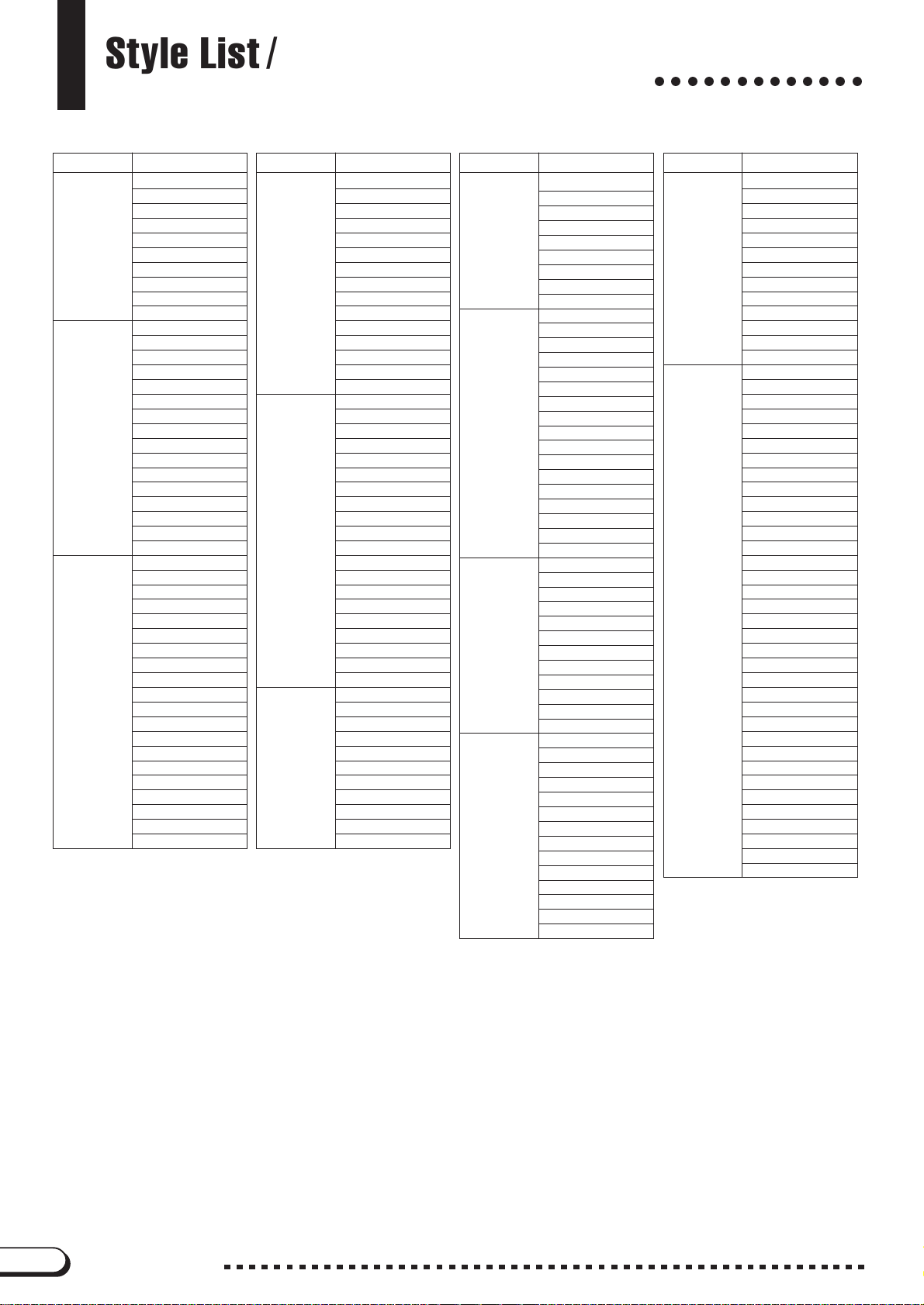
Style List / Style-Verzeichnis /
Liste des styles / Lista de estilos
○○○○○○○○○○○○○
Category Style Name
8 BEAT 8 Beat 1
8 Beat 2
8Bt Adria
8Bt Pop 1
8Bt Pop 2
British Pop
8 Beat Rock ◆
8 Beat Soft
8Beat Ballad
Light Pop
16 BEAT 16 Beat 1
16 Beat 2
16 Beat 3
16 Beat 4
16 Beat 5
Soft Fusion
Groundbeat ◆
Hip Hop Pop
16Bt Funk
Funky Pop
Funky Dance
80’s Fusion
Jazz Rock
●
Funk ◆
FusionShfl.
16 Beat 6
BALLAD 16-Ballad 1
16-Ballad 2
Piano Ballad
Rock Ballad
U.S. Ballad
Slow Rock 1
Slow Rock 2
Slow Ballad
Analog Pop
Modern 6/8
Pop Ballad 1
Pop Ballad 2
Cool Night
GuitarBallad
Organ Ballad
Pop Ballad 3
Pop Ballad 4 ◆
Blues Ballad ■ ◆
Epic Ballad
Pop Waltz
Category Style Name Category Style Name Category Style Name
DANCE Clubdance
Techno
SWING/JAZZ
Entrance
Eurobeat
Trance ◆
●
70’s Disco 1
80’s Disco ◆
●
*1
●
90’s Disco
Disco Soul
Cool Dance
Miami Pop
LATIN Samba Rio
Disco Tropic
Disco Hands
Electro Pop
70’s Disco 2 ◆
●
ROCK/R&B Rock 1
Hard Rock
R & Roll 1
●
●
*2
*3
Rock Shuffle
Gospel Shffl
R & B 1
*4
Twist 1
Motown
●
●
Soul ■ ◆
4/4 Blues
●
Rock 2
8 Beat Heat
R & Roll 2 ◆
●
COUNTRY Country Rock
Soul Shuffle
Pop Shuffle
R & B 2
Twist 2 ■ ◆
6/8 Blues
●
SWING/JAZZ
Blues Rock ■ ◆
6/8 Rock
Swing 1
●
●
*5
Big Band 1
BigBand Bld
Jazz Ballad
Jazz Trio
Boogie 1
●
●
Dixieland 1
BBand Boogie
Gypsy Swing
Bebop
Swing 2
• Styles marked with a ■ are not available on the CVP-107/700.
• Styles marked with a
• Styles marked with a
*1 “70’s Disco” on the CVP-105/103.
*2 “Rock” on the CVP-103.
*3 “R & Roll” on the CVP-105/103.
*4 “Twist” on the CVP-107/105/103/700.
*5 “Swing” on the CVP-103.
*6 “Boogie” on the CVP-107/105/103/700.
*7 “Bossa Nova” on the CVP-103.
*8 “Pop Bossa” on the CVP-105/103.
■
markierte Styles sind auf dem CVP-107/700 nicht verfügbar.
• Mit a
◆
markierte Styles sind auf dem CVP-105 nicht verfügbar.
• Mit a
●
markierte Styles sind auf dem CVP-103 nicht verfügbar.
• Mit a
*1 “70’s Disco” auf dem CVP-105/103.
*2 “Rock” auf dem CVP-103.
*3 “R & Roll” auf dem CVP-105/103.
*4 “Twist” auf dem CVP-107/105/103/700.
*5 “Swing” auf dem CVP-103.
*6 “Boogie” auf dem CVP-107/105/103/700.
*7 “Bossa Nova” auf dem CVP-103.
*8 “Pop Bossa” auf dem CVP-105/103.
◆
are not available on the CVP-105.
●
are not available on the CVP-103.
*6
●
●
BALLROOM Vienna Waltz
●
Big Band 2
Big Band 3 ■ ◆
Jazz Club 1 ■ ◆
Jazz Club 2 ■ ◆
Boogie 2 ■ ◆
●
Dixieland 2
Swing Ballad ■ ◆
●
TRAD./ U.S. March
WALTZ
●
●
●
Jazz Waltz 1
Jazz Waltz 2
Bossa Nova 1
Bossa Nova 2
Reggae ■ ◆
Swing Reggae
*7
●
●
PIANIST Stride 1
GuitarRhumba
Guitar Bossa
Salsa
Mambo
Pop Samba ◆
Jazz Samba
Pop Bossa 1
Pop Bossa 2 ◆
●
●
*8
●
Spanish Paso
Pop Reggae
Pop Rhumba ◆
Pop Cha Cha ◆
●
●
Country 8Bt
Country Pop
CntryShuffle
Cntry Swing
Bluegrass
Cntry Ballad
Two Step
CowboyBoogie
●
Hoedown
CountryWaltz
Folk
Slow Waltz
Slow Fox
Quickstep 1
Tango
Cha Cha
Samba
Rhumba
Pasodoble
Jive
Orch.Waltz
Beguine
Foxtrot
Quickstep 2
■
• Les styles marqués d’un
• Les styles marqués d’un
• Les styles marqués d’un
*1 “70’s Disco” sur le CVP-105/103.
*2 “Rock” sur le CVP-103.
*3 “R & Roll” sur le CVP-105/103.
*4 “Twist” sur le CVP-107/105/103/700.
*5 “Swing” sur le CVP-103.
*6 “Boogie” sur le CVP-107/105/103/700.
*7 “Bossa Nova” sur le CVP-103.
*8 “Pop Bossa” sur le CVP-105/103.
• Estilos marcados con una
• Estilos marcados con una
• Estilos marcados con una
*1 “70’s Disco” en la CVP-105/103.
*2 “Rock” en la CVP-103.
*3 “R & Roll” en la CVP-105/103.
*4 “Twist” en la CVP-107/105/103/700.
*5 “Swing” en la CVP-103.
*6 “Boogie” en la CVP-107/105/103/700.
*7 “Bossa Nova” en la CVP-103.
*8 “Pop Bossa” en la CVP-105/103.
n’existent pas sur le CVP-107/700.
◆
n’existent pas sur le CVP-105.
●
n’existent pas sur le CVP-103.
■
no están disponibles en la CVP-107/700.
◆
no están disponibles en la CVP-105.
●
no están disponibles en la CVP-103.
German March
6/8 March 1
Showtune
Polka Pop
Ober Polka
Oberkrain.W.
Tarantella
Musette
Guitar Waltz
6/8 March 2
Enka 1
Enka 2
Stride 2
Swing 1
Swing 2
Jazz Ballad
Blues 1
Blues 2
BoogieWoogie
Jazz Waltz
Arpeggio 1
8Bt Ballad 1
8Bt Ballad 2
8 Beat
Rock’n’ Roll
Slow Rock
2Beat Swing
Ragtime 1
Ragtime 2
March 1
6/8 March
4 Stroke
March 2
Musical
Traditional1
Traditional2
Traditional3
Arpeggio 2
Arpeggio 3
Waltz
Slow Waltz
Bossa Nova
Samba
Rhumba
Cha Cha
Beguine
12
CVP-109/107/105/103/700
Page 13
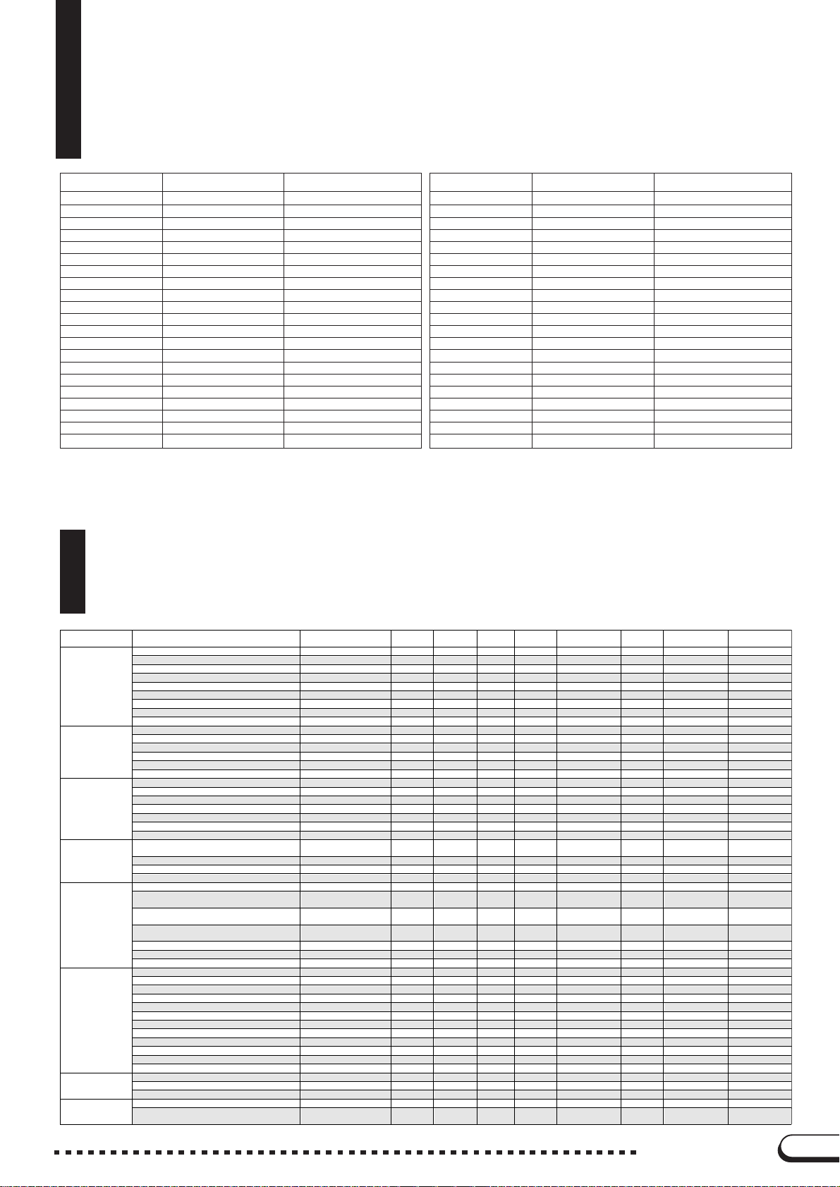
Vocal Harmony Type List (CVP-109/107/700) /
Liste Stimmharmonietyp
Liste des types d’harmonie vocale
Lista de tipos Vocal Harmony
(Vocal Harmony Type) (CVP-109/107/700)
(CVP-109/107/700) /
(CVP-109/107/700)
Display Name Harmony Type Harmony Mode Display Name Harmony Type Harmony Mode
Std:Duet Standard:Duet Chordal/Vocoder
Girl:Duet Girl:Duet Chordal/Vocoder
Lisa&Tina Lisa and Tina Chordal/Vocoder
Singer Singer Chordal/Vocoder
Dream Girls Dream Girls Chordal/Vocoder
MenChoir Men Choir Chordal/Vocoder
WomenChoir Women Choir Chordal/Vocoder
ClosedChoir Closed Choir Chordal/Vocoder
MixedChoir Mixed Choir Chordal/Vocoder
CountryMen Country Men Chordal/Vocoder
CntryGirls Country Girls Chordal/Vocoder
Barbershop Barbershop Chordal/Vocoder
MenCho:Jazz MenChoir:Jazz Chordal/Vocoder
WomenCho:J WomenCho:Jazz Chordal/Vocoder
CloseCho:J ClosedCho:Jazz Chordal/Vocoder
MixedCho:J MixedCho:Jazz Chordal/Vocoder
MenCho:Dia MenCho:Diatonic Chordal/Vocoder
Girl:Diatnc Girl:Diatonic Chordal/Vocoder
ACapellBoy A Capella Boy Chordal/Vocoder
ACapellaMix A Capella Mix Chordal/Vocoder
ACapellaDia A Capella Dia Chordal/Vocoder
Note: Vocal harmony types that have “
column can be used in either Chordal or Vocoder mode.
Hinweis: Stimmharmonietypen, die die Option “
Harmoniemodus besitzen, dürfen entweder im Modus “Chordal” oder im
Modus “Vocoder” benutzt werden.
Chordal/Vocoder
Chordal/Vocoder
” in the Harmony Mode
” in der Spalte
Falset:Duet Falsetto:Duet Chordal/Vocoder
Falsett:Trio Falsetto:Trio Chordal/Vocoder
Falsetto:Dia Falsetto:Dia Chordal/Vocoder
Falset:Jazz Falsetto:Jazz Chordal/Vocoder
FalACapella Fal A Capella Chordal/Vocoder
UnisonLow:2 Unison Low:2 Chordal/Vocoder
UnisonHigh:2 Unison High:2 Chordal/Vocoder
UnisonLow:3 Unison Low:3 Chordal/Vocoder
UnisonHigh:3 Unison High:3 Chordal/Vocoder
XG XG Chordal/Vocoder
Karaok:Duet Karaoke:Duet Chordal/Vocoder
Karaok:Trio Karaoke:Trio Chordal/Vocoder
KaraokGirl Karaoke:Girl Chordal/Vocoder
KaraokPich Karaoke:Pitch Chordal/Vocoder
SingBass Sing the Bass Chromatic
SpdyMouse Speedy Mouse Chromatic
ChromatXG ChromaticXG Chromatic
DetuneXG DetuneXG Detune
Voice&Inst Voice & Inst Chromatic
VoiceToInst Voice to Inst Chromatic
Thru Thru ---
Remarque : les types d’harmonie vocale comportant la valeur “
Nota: Los tipos Vocal harmony que presentan “
dans la colonne Harmony Mode peuvent être utilisés en mode Chordal
comme en mode Vocoder.
Chordal/Vocoder
modo de armonía pueden utilizarse en modo Chordal o Vocoder.
Chordal/Vocoder
” en la columna del
/
”
Parameter Chart / Parameterübersicht
/
Tableau des paramètres / Gráfica de parámetros
Group Contents Default V. Harmony
VOICE RIGHT1 VOICE Grand Piano — OOOVOICE SETTING O VOICE SETTING VOICE SETTING
DUAL DUAL ON/OFF OFF — O O O VOICE SETTING O VOICE SETTING VOICE SETTING
SPLIT SPLIT ON/OFF OFF — — O O VOICE SETTING O VOICE SETTING VOICE SETTING
ORGAN FLUTES
(109/107/700)
REVERB REVERB ON/OFF Depends on voice selection. — OOOREV/CHO/EFF O REV/CHO/EFF REV/CHO/EFF
EFFECT EFFECT ON/OFF Depends on v oice selection. — O O O REV/CHO/EFF O REV/CHO/EFF REV/CHO/EFF
CHORUS CHORUS ON/OFF (109/107/105/700) Depends on voice selection. — O O O REV/CHO/EFF O REV/CHO/EFF REV/CHO/EFF
EQUALIZER
(109/107/700)
RIGHT1 OCTAVE SHIFT 0 — O O O VOICE SETTING O VOICE SETTING VOICE SETTING
RIGHT1 PAN Center — OOOVOICE SETTING O VOICE SETTING VOICE SETTING
RIGHT1 VOLUME 127 — O O O VOICE SETTING O VOICE SETTING VOICE SETTING
Selected voice in each VOICE SELECT page Top voice — — — — — O VOICE SETTING VOICE SETTING
HARMONY ON/OFF OFF — O O O VOICE SETTING O VOICE SETTING VOICE SETTING
HARMONY TYPE Depends on voice selection. — OOOVOICE SETTING O VOICE SETTING VOICE SETTING
HARMONY VOLUME Depends on voice selection. — O O O VOICE SETTING O VOICE SETTING VOICE SETTING
HARMONY SPEED Depends on voice selection. — OOOVOICE SETTING O VOICE SETTING VOICE SETTING
RIGHT2 VOICE Strings Slow — OOOVOICE SETTING O VOICE SETTING VOICE SETTING
RIGHT2 OCTAVE SHIFT 0 — O O O VOICE SETTING O VOICE SETTING VOICE SETTING
DUAL DETUNE DEPTH 5 — OOOVOICE SETTING O VOICE SETTING VOICE SETTING
RIGHT2 PAN Center — O O O VOICE SETTING O VOICE SETTING VOICE SETTING
RIGHT2 VOLUME 127 — OOOVOICE SETTING O VOICE SETTING VOICE SETTING
LEFT VOICE Acous.Bass 1 — — OOVOICE SETTING O VOICE SETTING VOICE SETTING
LEFT OCTAVE SHIFT +1 — — O O VOICE SETTING O VOICE SETTING VOICE SETTING
SPLIT POINT F#2 — — — O VOICE SETTING O VOICE SETTING VOICE SETTING
LEFT PAN Center — — O O VOICE SETTING O VOICE SETTING VOICE SETTING
LEFT VOLUME 127 — — OOVOICE SETTING O VOICE SETTING VOICE SETTING
PEDAL RANGE RIGHT — — — O PEDAL O PEDAL PEDAL
ORGAN FLUTES VOICE JAZZ ORGAN — — OOVOICE SETTING O VOICE SETTING VOICE SETTING
1
FOOTAGE (16', 8', 5+1/3', 4', 2+2/3', 2', 1+1/3', 1') Depends on voice selection. — — O O VOICE SETTING O VOICE SETTING VOICE SETTING
ATTACK (4', 2+2/3', 2', LENGTH, RESPONSE) Depends on voice selection. — — OOVOICE SETTING O VOICE SETTING VOICE SETTING
ATTACK MODE (EACH/FIRST) Depends on voice selection. — — O O VOICE SETTING O VOICE SETTING VOICE SETTING
REVERB TYPE Depends on style (voice)
Natural Reverb Type (109) Depends on style (voice)
Reverb System (RIGHT1, RIGHT2, LEFT)
(109)
REVERB TOTAL DEPTH 64 — — OOREV/CHO/EFF O REV/CHO/EFF REV/CHO/EFF
REVERB PART DEPTH (RHYTHM, ACMP) 64 — — O O REV/CHO/EFF O REV/CHO/EFF REV/CHO/EFF
REVERB PART DEPTH (LEFT, RIGHT1, RIGHT2) Depends on voice selection. — OOOREV/CHO/EFF O REV/CHO/EFF REV/CHO/EFF
EFFECT TYPE (RIGHT1, RIGHT2, LEFT) (105/103) Depends on voice selection. — OOOREV/CHO/EFF O REV/CHO/EFF REV/CHO/EFF
EFFECT1 TYPE (109/107/700) Depends on voice selection. — O O O REV/CHO/EFF O REV/CHO/EFF REV/CHO/EFF
EFFECT2 TYPE (109/107/700) Depends on voice selection. — OOOREV/CHO/EFF O REV/CHO/EFF REV/CHO/EFF
EFFECT DEPTH (105/103) Depends on voice selection. — O O O REV/CHO/EFF O REV/CHO/EFF REV/CHO/EFF
EFFECT1 DEPTH (109/107/700) Depends on voice selection. — OOOREV/CHO/EFF O REV/CHO/EFF REV/CHO/EFF
EFFECT2 DEPTH (109/107/700) Depends on voice selection. — O O O REV/CHO/EFF O REV/CHO/EFF REV/CHO/EFF
EFFECT VARIATION (105/103) Depends on voice selection. — OOOREV/CHO/EFF O REV/CHO/EFF REV/CHO/EFF
EFFECT1 VARIATION (109/107/700) Depends on voice selection. — O O O REV/CHO/EFF O REV/CHO/EFF REV/CHO/EFF
EFFECT2 VARIATION (109/107/700) Depends on voice selection. — OOOREV/CHO/EFF O REV/CHO/EFF REV/CHO/EFF
EFFECT1 PART (109/107/700) RIGHT 1 — O O O REV/CHO/EFF O REV/CHO/EFF REV/CHO/EFF
EFFECT2 PART (109/107/700) RIGHT 2 — OOOREV/CHO/EFF O REV/CHO/EFF REV/CHO/EFF
CHORUS TYPE Depends on style selection. — — OOREV/CHO/EFF O REV/CHO/EFF REV/CHO/EFF
CHORUS DEPTH (RIGHT1, RIGHT2, LEFT) Depends on voice selection. — O O O REV/CHO/EFF O REV/CHO/EFF REV/CHO/EFF
2
EQUALIZER TYPE STANDARD — — — — VOICE SETTING O VOICE S ETTING VOICE SETTING
EQUALIZER GAIN Depends on equalizer type
selection.
selection.
Depends on voice selection. — O O O REV/CHO/EFF O REV/CHO/EFF REV/CHO/EFF
selection.
One Touch
Memory
— — O O REV/CHO/EFF O REV/CHO/EFF REV/CHO/EFF
— OOOREV/CHO/EFF O REV/CHO/EFF REV/CHO/EFF
— — — — VOICE SETTING O VOICE SETTING VOICE SETTING
Setting
Music
Database
Set Up
Memory
Registration Freeze
Group
All Set Up
Backup Group Recall Group
CVP-109/107/105/103/700
13
Page 14
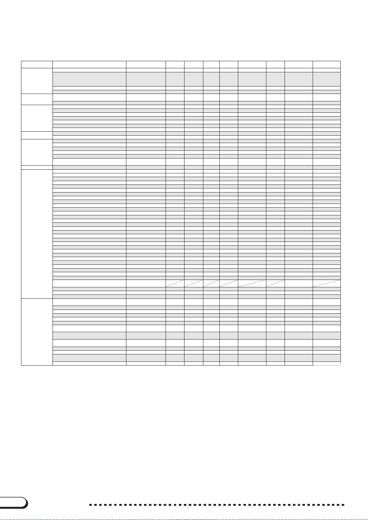
Parameter Chart / Parameterübersicht / Tableau des paramètres / Gráfica de parámetros
Group Contents Default V. Harmony
REGISTRATION REGISTRATION FREEZE ON /OFF O FF — ——— — —REGISTRATION REGISTRATION
MIXER MIXER PART VOLUME (RHYTHM, BASS, CHORD,
ACCOMPANIMENT STYLE 8 Beat 1 ——O — ACMP. SETTING O ACMP SETTING ACMP SETTING
METRONOME METRONOME TYPE NORMAL — — — — — O ACMP SETTING ACMP SETTING
SONG GUIDE MODE NORMAL — — — — —
HELP LANGUAGE ENGLISH — — — — — O Always backed up. —
FUNCTION TUNE 440.0Hz (A3) — ——— — O TUNE TUNE
VOCAL HARMONY
(109/107/700)
1 The One Touch Setting function can only set this parameter for the RIGHT1 part. The
Registration function and All Set Up files can set this item for the RIGHT1, RIGHT2, and
LEFT parts. Parameters related to the Organ Flutes voice will be recalled with a registration, Music Database setup, or All Setup file only if the Organ Flutes voice is selected
by the recalled data.
2 The Registration function only stores the gain values for the currently selected equalizer
type. The Backup function backs up the gain values for all equalizer types.
3 When a Music Database setup or registration is recalled during Auto Accompaniment
playback, the style thereby selected will begin playing immediately if it is the same as
the style that is currently playing, or from the top of the next measure if it is a different
style.
4 REGISTRATION: ON; Others: OFF
1 Die Funktion One Touch-Einstellungen aktiviert diesen Parameter nur für den Part
RIGHT1. Die Registrierungsfunktion und die All Setup-Dateien ermöglichen das
Einstellen dieses Elements für die Parts RIGHT1, RIGHT2 und LEFT. Parameter, die
sich auf den Orgelpfeifenklang beziehen, können nur dann mit einer Registrierungs-,
Musikdatenbank-Setup- oder All Setup-Datei wieder aufgerufen werden, wenn der
Orgelpfeifenklang über die Aufrufdaten ausgewählt wurde.
2 Die Registrierungsfunktion speichert die gewonnenen Werte nur zum aktuell gewählten
Equalizertyp ab. Die Backup-Funktion speichert die gewonnenen Werte zu sämtlichen
Equalizertypen ab.
3 Bei Wiederaufruf eines Musikdatenbank-Setup oder einer Registrierung während des
Auto Accompaniment-Backup (Backup von Autom. Begleitung) wird der dabei gewählte
Style sofort abgespielt, sofern dieser derselbe ist wie der aktuell abgespielte Style, oder
ab der obersten Stelle des nächsten Taktes, falls es sich um einen anderen Style
handelt.
4 REGISTRATION: ON; Andere: OFF
FREEZE CATEGORY ON/OFF (VOICE SETTING,
REV/CHO/EFF
TUNE, PEDAL, ACMP.SETTING, VOCAL HARMONY
(109/107/700)
REGISTRATION NAME (109/107/105/700) REGIST Bank-Num. — ———Always recalled. O REGISTRATION REGISTRATION
ALL REGISTRATION Memory Da ta (20) Factory preset data — — — —
PAD, PHRASE)
KEYBOARD VOLUME 127 — — O O VOICE SETTING O VOICE SETTING VOICE SETTING
Selected style in each STYLE SELECT page Top style — — — — — O ACMP SETTING ACMP SETTING
MAIN A/B /C/D MAIN C ——O — ACMP. SETTING O ACMP SETTING ACMP SETTING
ACMP. ON/O FF OFF — ON ON — ACMP. SETTING O ACMP SETTING ACMP SETTING
ACCOMPANIMENT MODE MULTI FINGER ————ACMP. SETTING O ACMP SETTING ACMP SETTING
TEMPO
INTRO/FILL IN/ENDING O FF — ———ACMP. SETTING O ——
METRONOME VOLUME 64 — ——— — O ACMP SETTING ACMP SETTING
SOUND REPEAT AUTO — ——— — O SONG SETTING SONG SETTING
PIANO ROLL DISPLAY AUTO — — — — — O SONG SETTING SONG SETTING
GUIDE LAMP ON/ OFF ON ———— — O SONG SETTING SONG SETTING
LYRICS ON/O FF ON — — — —
SONG VOLUME [ACMP/SONG VOLUME]
TRANSPOSE (ALL) 0 — ———VOICE SETTING O VOICE SETTING VOICE SETTING
TRANSPOSE (SONG) 0 — — — — — O VOICE SETTING VOICE SETTING
VOICE SETTING AUTO — ——— — O VOICE SETTING VOICE SETTING
KEY TOUCH NORMAL — — — — VOICE SETTING O VOICE SETTING VOICE SETTING
FIXED VELOCITY 76 — ———VOICE SETTING O VOICE SETTING VOICE SETTING
LEFT PEDAL FUNCTION SOFT — — O O PEDAL O PEDAL PEDAL
RIGHT PEDAL FUNCTION (109/107/700)
LEFT PART MIDI SEND Ch. 3 — — — — — O MIDI SETTING MIDI SETTING
RIGHT 1 PART MIDI SEND Ch . 1 — ——— — O MIDI SETTING MIDI SETTING
RIGHT 2 PART MIDI SEND Ch. 2 — — — — — O MIDI SETTING MIDI SETTING
LOCAL CONTROL ON/OF F ON — ——— — O MIDI SETTING MIDI SETTING
SYNC. CLOCK INT. — — — — — O MIDI SETTING MIDI SETTING
PROGRAM CHANGE SEND/RECEIVE ON/O FF TX&RX (ON) — ——— — O MIDI SETTING MIDI SETTING
CONTROL CHANGE SEND/RECEIVE ON/OFF TX&RX (ON) — — — — — O MIDI SETTING MIDI SETTING
SYSTEM EXCLUSIVE SEND/RECEIVE ON/O FF TX&RX (ON) — ——— — O MIDI SETTING MIDI SETTING
START/STOP SEND/RECEIVE ON/OF F OFF — — — — — O MIDI SETTING MIDI SETTING
MIDI FILTER ON/OFF (all channels) O N — ——— — O MIDI SETTING MIDI SETTING
MIDI TRANSPOSE RECEIVE ON/ OFF ON — — — — — O MIDI SETTING MIDI SETTING
ACMP & RHY SEND ON /OF F O F F ———— — O MIDI SETTING MIDI SETTING
HARMONY SEND O N/ OFF OFF — — — — — O MIDI SETTING MIDI SETTING
SEQUENCER SEND ON/ OFF O F F ———— — O MIDI SETTING MIDI SETTING
REMOTE KEYBOARD OFF — — — — — O MIDI SETTING MIDI SETTING
MICRO TUNING O N/O FF OF F — ——— — O TUNE TUNE
MICRO TUNE. SETTING 0 — — — — — O TUNE TUNE
SCALE TUNING SELECT PRESET — ——— TUNE O TUNE TUNE
PRESET SCALE SELECT EQUAL — — — — TUNE O TUNE TUNE
PRESET SCALE KEY C — ——— TUNE O TUNE TUNE
USER SCALE SETTING 0 — — — — TUNE O TUNE TUNE
BACKUP ON/O FF Set separately for each
Video Out Screen SIZE (109/107/700) LARGE — — — — — — Always backed up. —
Video Out CHARACTER Color (109/107/700) BLUE (19) — ——— — —Always backed up. —
Video Out BACKGROUND Color (109/107/700) WHITE — — — — — — Always backed up. —
VOCAL HARMONY O N/O FF OF F O ———VOCAL HARMONY O VOCAL HARMONY VOCAL HARMONY
VOCAL HARMONY TYPE MenChoir O — — — VOCAL HARMONY O VOCAL HARMONY VOCAL HARMONY
VOCAL HARMONY REVERB DEPTH 64 O ———VOCAL HARMONY O VOCAL HARMONY VOCAL HARMONY
VOCAL HARMONY CHORUS DEPTH 0 O — — — VOCAL HARMONY O VOCAL HARMONY VOCAL HARMONY
VOCAL HARMONY EFFECT DEPTH 50 O ———VOCAL HARMONY O VOCAL HARMONY VOCAL HARMONY
VOCAL HARMONY EFFECT TYPE KARAOKE1 O — — — VOCAL HARMONY O VOCAL HARMONY VOCAL HARMONY
VOCAL HARMONY BALANCE Depends on Vocal Harmony
VOCAL HARMONY PITCH TO NOTE PART Depends on Vocal Harmony
VOCAL HARMONY GENDER TYPE Depends on Vocal Harmony
VOCAL HARMONY HARMONY PART Automatically set O — — — VOCAL HARMONY O VOCAL HARMONY VOCAL HARMONY
VOCAL HARMONY HARMONY MODE AUTO O ———VOCAL HARMONY O VOCAL HARMONY VOCAL HARMONY
VOCAL HARMONY PITCH CORRECTION Depends on Vocal Harmony
VOCAL HARMONY LOCK ON/OF F OFF ———— — O VOCAL HARMONY VOCAL HARMONY
3
(109/107/700),
REVERB/EFFECT
ACMP. SETTING: ON
(105/103),
Others: OF F
110 ——O ACMP. SETTING O ACMP SETTING ACMP SETTING
Depends on style selection. — — O — ACMP. SETTING O ACMP SETTING ACMP SETTING
slider val ue
Depends on R1 voice selection.
4
group.
type.
type.
type.
type.
One Touch
Memory
— — — — — — REGISTRATION REGISTRATION
—— — SONG SETTING
——OOVOICE SETTING O VOICE SETTING VOICE SETTING
O ———VOCAL HARMON Y O VOCAL HARMONY VOCAL HARMONY
O — — — VOCAL HARMONY O VOCAL HARMONY VOCAL HARMONY
O ———VOCAL HARMONY O VOCAL HARMONY VOCAL HARMONY
O — — — VOCAL HARMONY O VOCAL HARMONY VOCAL HARMONY
1 La fonction One Touch Setting ne peut définir ce paramètre que pour la partie RIGHT1.
2 La fonction Registration ne conserve les valeurs de gain que pour le type d’égaliseur
3 Si une configuration de Music Database ou une registration est rappelée au cours de
4 REGISTRATION : ON ; Autres : OFF
1 La función One Touch Setting sólo puede ajustar este parámetro para la parte RIGHT1.
2 La función Registration sólo almaneca los valores de ganancia para el tipo de
3 Cuando un registro o los ajustes Music Database están llamados durante una
4 REGISTRATION: ON; Otros: OFF
Music
Set Up
Setting
Database
—— —
La fonction Registration et les fichiers All Set Up peuvent définir ce paramètre pour les
parties RIGHT1, RIGHT2, et LEFT. Les paramètres liés à la voix Organ Flute ne seront
rappelés avec une registration, une configuration de Music Database, ou un fichier All
Setup que si la voix Organ Flutes est sélectionnée par les données rappelées.
sélectionné. La fonction Backup sauvegarde les valeurs de gain pour tous les types
d’égaliseur.
l’accompagnement automatique, le style ainsi sélectionné sera joué immédiatement s’il
est identique au style en cours de lecture, ou au début de la mesure suivante s’il s’agit
d’un style différent.
La función Registration y los archivos All Set Up pueden ajustar este ítem para las
partes RIGHT1, RIGHT2 y LEFT. Los parámetros relacionados con la voz Organ Flutes
estarán llamados por un registro, los ajustes Music Database o un archivo All Setup
sólo si la voz Organ Flutes se selecciona por los datos llamados.
ecualizador seleccionado. La función Backup respalda los valores de ganancia para
todos los tipos de ecualizador.
reproducción Auto Accompaniment, el estilo seleccionado reproducirá inmediatamente
si es el mismo que el estilo que se está reproduciendo o desde el principio del compás
siguiente si es un estilo diferente.
Memory
—
Registration Freeze
Group
— O REGISTRATION REGISTRATION
— O SONG SETTING SONG SETTING
All Set Up
Backup Group Recall Group
—— —
—
Always backed up.
14
CVP-109/107/105/103/700
Page 15
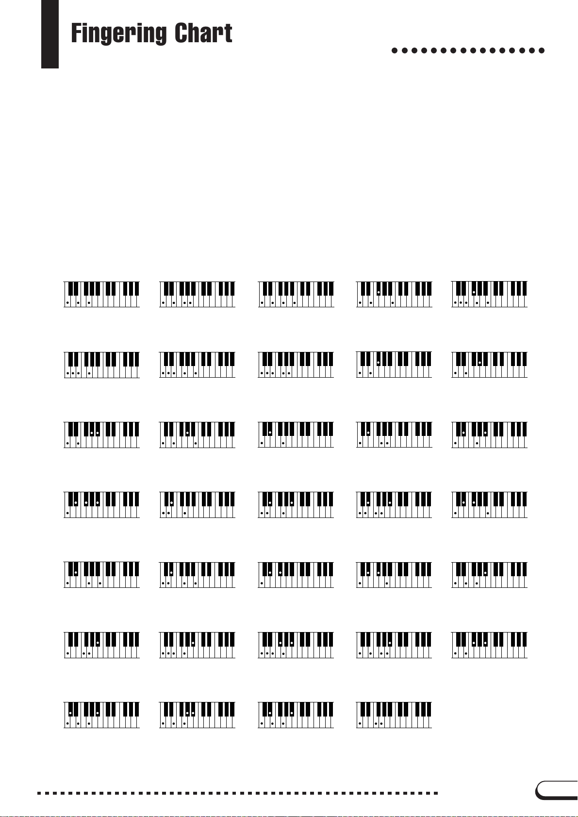
Fingering Chart / Akkordliste / Tablature / Gráfica de digitado
* All fingerings shown are simple root-position types.
* Die hier gezeigten Akkorde sind jeweils die Grundakkorde.
* Tous les doigtés indiqués sont du type à position fondamentale simple.
* Todos los digitados se muestran como tipos de posición de raíz sencilla.
Example for “C” chords
Beispiele für “C”-Akkorde
Exemples d’accords en “C”
Ejemplo de acordes “C”
○○○○○○○○○○○○○○○○
C
Cadd
(#5)
C
7
Cm
CmM
C
6
( )
(9)
9
(b5)
7
7
CM
7
(#5)
CM
7
( )
Cmadd
CmM
( )
9
(9)
7
CM
C
Cm
Cm
Cm
7
( )
(9)
6
( )
(9)
7
( )
(b5)
CM
(b5)
C
Cm
Cm
( )
Cdim
(b5)
7
6
(11)
7
( )
7
CM
Caug
Cm
CmM
C
7
7
7
(#11)
( )
( )
(b5)
7
C sus
7
(b9)
C
7
( )
4
( )
( )
( )
(9)
C
7
( )
(b13)
C
7
(#11)
C
7
( )
(#9)
C
7
( )
C
7
Csus
(13)
( )
4
CVP-109/107/105/103/700
( )
(b5)
C
7
15
Page 16
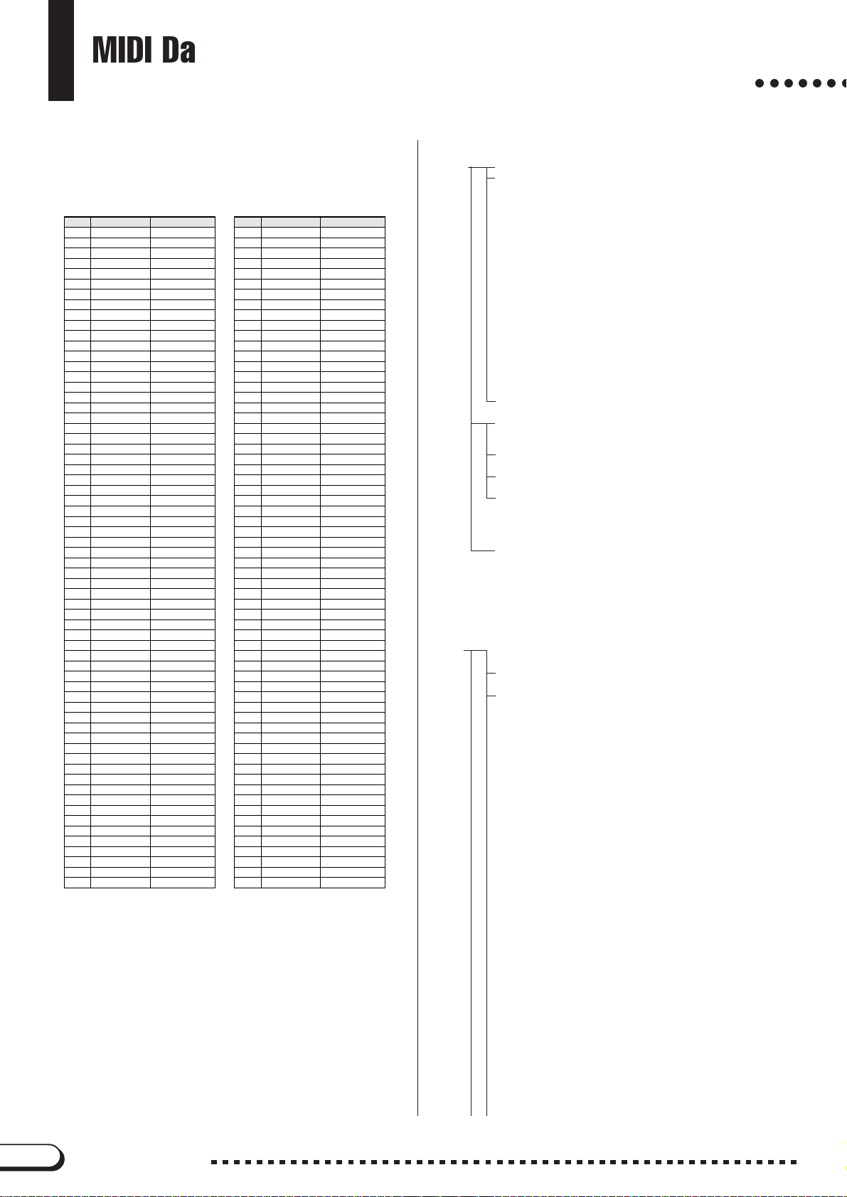
MIDI Data Format / MIDI-Datenformat /
Format des données MIDI / Formato de datos MIDI
○○○○○○○
Many MIDI messages listed in the MIDI Data Format are expressed in decimal
numbers, binary numbers and hexadecimal numbers. Hexadecimal numbers
may include the letter “H” as a suffix. Also, “n” can freely be defined as any
whole number.
To enter data/values, refer to the table below.
Decimal Hexadecimal Binary Decimal Hexadecimal Binary
0 00 0000 0000
1 01 0000 0001
2 02 0000 0010
3 03 0000 0011
4 04 0000 0100
5 05 0000 0101
6 06 0000 0110
7 07 0000 0111
8 08 0000 1000
9 09 0000 1001
10 0A 0000 1010
11 0B 0000 1011
12 0C 0000 1100
13 0D 0000 1101
14 0E 0000 1110
15 0F 0000 1111
16 1 0 0001 0000
17 1 1 0001 0001
18 1 2 0001 0010
19 1 3 0001 0011
20 1 4 0001 0100
21 1 5 0001 0101
22 1 6 0001 0110
23 1 7 0001 0111
24 1 8 0001 1000
25 1 9 0001 1001
26 1A 0001 1010
27 1B 0001 1011
28 1C 0001 1100
29 1D 0001 1101
30 1E 0001 1110
31 1F 0001 1111
32 2 0 0010 0000
33 2 1 0010 0001
34 2 2 0010 0010
35 2 3 0010 0011
36 2 4 0010 0100
37 2 5 0010 0101
38 2 6 0010 0110
39 2 7 0010 0111
40 2 8 0010 1000
41 2 9 0010 1001
42 2A 0010 1010
43 2B 0010 1011
44 2C 0010 1100
45 2D 0010 1101
46 2E 0010 1110
47 2F 0010 1111
48 3 0 0011 0000
49 3 1 0011 0001
50 3 2 0011 0010
51 3 3 0011 0011
52 3 4 0011 0100
53 3 5 0011 0101
54 3 6 0011 0110
55 3 7 0011 0111
56 3 8 0011 1000
57 3 9 0011 1001
58 3A 0011 1010
59 3B 0011 1011
60 3C 0011 1100
61 3D 0011 1101
62 3E 0011 1110
63 3F 0011 1111
64 4 0 0100 0000
65 4 1 0100 0001
66 4 2 0100 0010
67 4 3 0100 0011
68 4 4 0100 0100
69 4 5 0100 0101
70 4 6 0100 0110
71 4 7 0100 0111
72 4 8 0100 1000
73 4 9 0100 1001
74 4A 0100 1010
75 4B 0100 1011
76 4C 0100 1100
77 4D 0100 1101
78 4E 0100 1110
79 4F 0100 1111
80 5 0 0101 0000
81 5 1 0101 0001
82 5 2 0101 0010
83 5 3 0101 0011
84 5 4 0101 0100
85 5 5 0101 0101
86 5 6 0101 0110
87 5 7 0101 0111
88 5 8 0101 1000
89 5 9 0101 1001
90 5A 0101 1010
91 5B 0101 1011
92 5C 0101 1100
93 5D 0101 1101
94 5E 0101 1110
95 5F 0101 1111
96 6 0 0110 0000
97 6 1 0110 0001
98 6 2 0110 0010
99 6 3 0110 0011
100 64 0110 0100
101 65 0110 0101
102 66 0110 0110
103 67 0110 0111
104 68 0110 1000
105 69 0110 1001
106 6A 0110 1010
107 6B 0110 1011
108 6C 0110 1100
109 6D 0110 1101
110 6E 0110 1110
111 6F 0110 1111
112 70 0111 0000
113 71 0111 0001
114 72 0111 0010
115 73 0111 0011
116 74 0111 0100
117 75 0111 0101
118 76 0111 0110
119 77 0111 0111
120 78 0111 1000
121 79 0111 1001
122 7A 0111 1010
123 7B 0111 1011
124 7C 0111 1100
125 7D 0111 1101
126 7E 0111 1110
127 7F 0111 1111
• Except the table above, for example 144-159(decimal)/9nH/1001 0000-1001
1111(binary) displays the Note On Message for each channel (1-16). 176-191/
BnH/1011 0000-1011 1111 displays the Control Change Message for each
channel (1-16). 192-207/CnH/1100 0000-1100 1111 displays the Program
Change Message for each channel (1-16). 240/F0H/1111 0000 denotes the
start of a System Exclusive Message. 247/F7H/1111 0111 denotes the end of
a System Exclusive Message.
• aaH (hexidecimal)/0aaaaaaa (binary) denotes the data address. The address
contains High, Mid, and Low.
• bbH/0bbbbbbb denotes the byte count.
• ccH/0ccccccc denotes the check sum.
• ddH/0ddddddd denotes the data/value.
(1) TRANSMIT FLOW
MIDI← KEY OFF 8nH
OUT KEY ON/OFF 9nH
CONTROL CHANGE BnH
BANK SELECT MSB BnH,00H
BANK SELECT LSB BnH,20H
DATA ENTRY MSB BnH,06H
DATA ENTRY LSB BnH,26H
MAIN VOLUME BnH,07H
PANPOT BnH,0AH
EXPRESSION BnH,0BH
SUSTAIN BnH,40H
SOSTENUTE BnH,42H
SOFT PEDAL BnH,43H
PORTAMENTO CONTROL BnH,54H
REVERB SEND LEVEL BnH,5BH
CHORUS SEND LEVEL BnH,5DH
VARIATION SEND LEVEL BnH,5EH
RPN LSB BnH,64H
RPN MSB BnH,65H
PITCH BEND SENS. BnH,65H,00H,64H,00H,06H,mmH
PROGRAM CHANGE CnH
SYSTEM EXCLUSIVE MESSAGE
<YAMAHA MIDI FORMAT>
<UNIVERSAL>
UNIVERSAL NON-REALTIME F0H 7EH.....F7H
<XG STANDARD>
XG PARAMETER CHANGE
XG BULK DUMP
<CLAVINOVA MIDI COMPLIANCE>
<SPECIAL OPERATORS>
SYSTEM REALTIME MESSAGE
MIDI CLOCK F8H
START FAH
STOP FCH
ACTIVE SENSING FEH
(2) RECEIVE FLOW
MIDI →KEY OFF 8nH
IN
KEY ON/OFF 9nH
CONTROL CHANGE
BANK SELECT MSB BnH,00H
BANK SELECT LSB BnH,20H
MODULATION BnH,01H
PORTAMENTO TIME BnH,05H
DATA ENTRY MSB BnH,06H
DATA ENTRY LSB BnH,26H
MAIN VOLUME BnH,07H
PANPOT BnH,0AH
EXPRESSION BnH,0BH
SUSTAIN BnH,40H
PORTAMENTO BnH,41H
SOSTENUTO BnH,42H
SOFT PEDAL BnH,43H
HARMONIC CONTENT BnH,47H
RELEASE TIME BnH,48H
ATTACK TIME BnH,49H
BRIGHTNESS BnH,4AH
PORTAMENTO CONTROL BnH,54H
REVERB SEND LEVEL BnH,5BH
CHORUS SEND LEVEL BnH,5DH
VARIATION SEND LEVEL BnH,5EH
DATA INCREMENT BnH,60H
DATA DECREMENT BnH,61H
NRPN LSB BnH,62H
NRPN MSB BnH,63H
VIBRATO RATE BnH,63H,01H,62H,08H,06H,mmH
VIBRATO DEPTH BnH,63H,01H,62H,09H,06H,mmH
VIBRATO DELAY BnH,63H,01H,62H,0AH,06H,mmH
FILTER CUTOFF FREQ. BnH,63H,01H,62H,20H,06H,mmH
FILTER RESONANCE BnH,63H,01H,62H,21H,06H,mmH
EQ BASS (CVP-109/107/700) BnH,63H,01H,62H,30H,06H,mmH
EQ TREBLE (CVP-109/107/700) BnH,63H,01H,62H,31H,06H,mmH
EQ BASS FREQ.
EQ TREBLE FREQ. (CVP-109/107/700)
EG ATTACK TIME BnH,63H,01H,62H,63H,06H,mmH
EG DECAY TIME BnH,63H,01H,62H,64H,06H,mmH
EG RELEASE BnH,63H,01H,62H,66H,06H,mmH
DRUM INST *1
CUTOFF FREQ. BnH,63H,14H,62H,rrH,06H,mmH
(CVP-109/107/700)
F0H 43H 1nH 4CH aaH aaH aaH ddH
F0H 43H 0nH 4CH bbH bbH aaH aaH
aaH ddH.....ddH ccH F7H
BnH,63H,01H,62H,34H,06H,mmH
BnH,63H,01H,62H,35H,06H,mmH
.....ddH F7H
16
CVP-109/107/105/103/700
Page 17
FILTER RESONANCE BnH,63H,15H,62H,rrH,06H,mmH
EG ATTACK RATE BnH,63H,16H,62H,rrH,06H,mmH
EG DECAY RATE BnH,63H,17H,62H,rrH,06H,mmH
PITCH COARSE BnH,63H,18H,62H,rrH,06H,mmH
PITCH FINE BnH,63H,19H,62H,rrH,06H,mmH
LEVEL BnH,63H,1AH,62H,rrH,06H,mmH
PANPOT BnH,63H,1CH,62H,rrH,06H,mmH
REVERB SEND BnH,63H,1DH,62H,rrH,06H,mmH
CHORUS SEND BnH,63H,1EH,62H,rrH,06H,mmH
VARIATION SEND BnH,63H,1FH,62H,rrH,06H,mmH
RPN LSB BnH,64H
RPN MSB BnH,65H
PITCH BEND SENS. BnH,65H,00H,64H,00H,06H,mmH
FINE TUNING BnH,65H,00H,64H,01H,06H,mmH,
COARSE TUNING BnH,65H,00H,64H,02H,06H,mmH
NULL BnH,65H,7FH,64H,7FH
ALL SOUND OFF BnH,78H,00H
RESET ALL CONTROLLERS BnH,79H,00H
ALL NOTES OFF BnH,7BH,00H
OMNI OFF BnH,7CH,00H
OMNI ON BnH,7DH,00H
MONO BnH,7EH
POLY BnH,7FH
PROGRAM CHANGE CnH
CHANNEL AFTER TOUCH DnH
PITCH BEND CHANGE EnH
SYSTEM EXCLUSIVE MESSAGE
<YAMAHA MIDI FORMAT>
<UNIVERSAL>
UNIVERSAL REALTIME F0H 7FH.....F7H
UNIVERSAL NON-REALTIME F0H 7EH.....F7H
<XG STANDARD>
XG PARAMETER CHANGE
XG BULK DUMP
PARAMETER REQUEST
DUMP REQUEST
<CLAVINOVA MIDI COMPLIANCE>
<SPETIAL OPERATORS>
<Others>
SYSTEM REALTIME MESSAGE
MIDI CLOCK F8H
START FAH
STOP FCH
ACTIVE SENSING FEH
F0H 43H 1nH 4CH aaH aaH aaH ddH
F0H 43H 0nH 4CH bbH bbH aaH aaH
aaH ddH.....ddH ccH F7H
F0H 43H 3nH 4CH aaH aaH aaH F7H
F0H 43H 2nH 4CH aaH aaH aaH F7H
(3) TRANSMIT/RECEIVE DATA
(3-1) CHANNEL VOICE MESSAGES
(3-1-1) KEY OFF
STATUS 1000nnnn(8nH) n = 0 - 15 VOICE CHANNEL NUMBER
NOTE NUMBER 0kkkkkkk k = 0 (C-2) - 127 (G8)
VELOCITY 0vvvvvvv v: ignored
(3-1-2) KEY ON/OFF
STATUS 1001nnnn(9nH) n = 0 - 15 VOICE CHANNEL NUMBER
NOTE NUMBER 0kkkkkkk k = 0 (C-2) - 127 (G8)
VELOCITY 0vvvvvvv (v ≠ 0) NOTE ON
(3-1-3) PROGRAM CHANGE
STATUS 1100nnnn(CnH) n = 0 - 15 VOICE CHANNEL NUMBER
PROGRAM NUMBER 0ppppppp p = 0 - 127
* PROGRAM NUMBER: XG DRUM VOICE number correspondence
P = 0 Standard Kit
P = 1 Standard2 Kit
P = 4 Hit Kit (CVP-109/107/700)
P = 8 Room Kit
P = 16 Rock Kit
P = 24 Electro Kit
P = 25 Analog Kit
P = 27 Dance Kit
P = 32 Jazz Kit
P = 40 Brush Kit
P = 48 Classic Kit
* PROGRAM NUMBER: XG SFX KIT number correspondence
P = 0 SFX1 Kit
P = 1 SFX2 Kit
When DRUM VOICE is selected and program change data for a different DRUM VOICE is
received, the currently selected Drum Setup data will be replaced with the new DRUM
VOICE DATA.
00000000 (v = 0) NOTE OFF
26H,llH
.....ddH F7H
(3-1-4) CHANNEL AFTER TOUCH (Receive only)
STATUS 1101nnnn(DnH) n = 0 - 15 VOICE CHANNEL NUMBER
VALUE 0vvvvvvv v = 0 - 127 AFTER TOUCH VALUE
(3-1-5) PITCH BEND CHANGE
STATUS 1110nnnn(EnH) n = 0 - 15 VOICE CHANNEL NUMBER
LSB 0vvvvvvv PITCH BEND CHANGE LSB
MSB 0vvvvvvv PITCH BEND CHANGE MSB
(3-1-6) CONTROL CHANGE
STATUS 1011nnnn(BnH) n = 0 - 15 VOICE CHANNEL NUMBER
CONTROL NUMBER 0ccccccc
CONTROL VALUE 0vvvvvvv
* Transmit CONTROL NUMBER.
c = 0 BANK SELECT MSB ; v = 0:XG NORMAL,
c = 32 BANK SELECT LSB ; v = 0 - 127
c = 6 DATA ENTRY MSB ; v = 0 - 127 *1
c = 38 DATA ENTRY LSB ; v = 0 - 127 *1
c = 7 MAIN VOLUME ; v = 0 - 127
c = 10 PANPOT; v = 0 - 127
c = 11 EXPRESSION ; v = 0 - 127
c = 64 SUSTAIN ; v = 0-63:OFF , 64-127:ON *2
c = 66 SOSTENUTO ; v = 0-63:OFF , 64-127:ON *2
c = 67 SOFT PEDAL ; v = 0-63:OFF , 64-127:ON *2
c = 84 PORTAMENTO CONTROL ; v = 0 - 127
c = 91 REVERB SEND LEVEL ; v = 0 - 127
c = 93 CHORUS SEND LEVEL ; v = 0 - 127
c = 94
c = 100 RPN LSB ; v = 0 - 127
c = 101 RPN MSB ; v = 0 - 127
* Receive CONTROL NUMBER.
c = 0 BANK SELECT MSB ; v = 0:XG NORMAL,
c = 32 BANK SELECT LSB ; v = 0 - 127
c = 1 MODULATION ; v = 0 - 127 *2
c = 5 PORTAMENTO TIME ; v = 0 - 127 *2
c = 6 DATA ENTRY MSB ; v = 0 - 127 *1
c = 38 DATA ENTRY LSB ; v = 0 - 127 *1
c = 7 MAIN VOLUME ; v = 0 - 127
c = 10 PANPOT; v = 0 - 127
c = 11 EXPRESSION ; v = 0 - 127
c = 64 SUSTAIN ; v = 0-63:OFF , 64-127:ON *2
c = 65 PORTAMENTO ; v = 0-63:OFF , 64-127:ON *2
c = 66 SOSTENUTO ; v = 0-63:OFF , 64-127:ON *2
c = 67 SOFT PEDAL ; v = 0-63:OFF , 64-127:ON *2
c = 71 HARMONIC CONTENT ;
c = 72 RELEASE TIME ;
c = 73 ATTACK TIME ;
c = 74 BRIGHTNESS ;
c = 84 PORTAMENT CONTROL ; v = 0 - 127 *2
c = 91 REVERB SEND LEVEL ; v = 0 - 127
c = 93 CHORUS SEND LEVEL ; v = 0 - 127
c = 94
c = 96 DATA INCREMENT ; v = 0 - 127 *1
c = 97 DATA DECREMENT ; v = 0 - 127 *1
*1 Only when setting the appointed parameter with RPN, NRPN.
*2 Does not effect Rhythm Voice.
VARIATION SEND LEVEL
VARIATION SEND LEVEL
RPN MSB/LSB, NRPN MSB/LSB
64:SFX NORMAL,
126:XG SFX KIT,
127:XG DRUM
; v = 0 - 127
(When only Connection = 1[System])
64:SFX NORMAL,
126:XG SFX KIT,
127:XG DRUM
v = 0:-64 - 64:0 - 127:+63 *2
v = 0:-64 - 64:0 - 127:+63 *2
v = 0:-64 - 64:0 - 127:+63 *2
v = 0:-64 - 64:0 - 127:+63 *2
; v = 0 - 127
(When only Connection = 1[System])
• Until a PROGRAM CHANGE message is received, the BANK SELECT
operation will be suspended. When a Voice, including VOICE BANK, is
changed, set the BANK SELECT and Program Change Message, and
transmit in the following order, BANK SELECT MSB, LSB, PROGRAM
CHANGE.
• MODULATION controls the Vibrato Depth.
• PORTAMENTO TIME controls the Pitch Change Speed when the
Portamento Switch = ON. 0 being the shortest time, and 127 being the
longest.
• PANPOT changes the value for the melody voice and rhythm voice in
relation to the preset value.
• Portamento time is fixed to 0 when the PORTAMENTO CONTROL is
used.
CVP-109/107/105/103/700
17
Page 18

MIDI Data Format / MIDI-Datenformat / Format des données MIDI / Formato de datos MIDI
○ ○
• HARMONIC CONTENT applies adjustment to the resonance value that
is set by the voice. This parameter specifies relative change with the
value of 64 producing 0 adjustment. As values get higher the sound
becomes increasingly eccentric. Note that for some voices the effective
parameter range is narrower than the legal parameter range.
• RELEASE TIME applies adjustment to the envelope release time set by
the voice. This parameter specifies relative change with the value of 64
producing 0 adjustment.
• ATTACK TIME applies adjustment to the envelope attack time set by the
voice. This parameter specifies relative change with the value of 64
producing 0 adjustment.
• BRIGHTNESS applies adjustment to the cut-off frequency set by the
voice. This parameter specifies relative change with the value of 64
producing 0 adjustment. Lower voices produce a softer sound. For some
voices the effective parameter range is narrower than the legal
parameter range.
(3-2) CHANNEL MODE MESSAGES
STATUS 1011nnnn(BnH) n = 0 - 15 VOICE CHANNEL NUMBER
CONTROL NUMBER 0ccccccc c = CONTROL NUMBER
CONTROL VALUE 0vvvvvvv v = DATA VALUE
(3-2-1) ALL SOUND OFF (Receive only)
(CONTROL NUMBER = 78H , DATA VALUE = 0)
Switches off all sound from the channel. Reset Note On and Hold On conditions established
by Channel Messages.
(3-2-2) RESET ALL CONTROLLERS (Receive only)
(CONTROL NUMBER = 79H , DATA VALUE = 0)
Resets controllers as follows.
PITCH BEND CHANGE 0 (Center)
AFTER TOUCH 0 (min.)
MODULATION 0 (min.)
EXPRESSION 127 (max.)
SUSTAIN 0 (off)
SOSTENUTO 0 (off)
SOFT PEDAL 0 (off)
NRPN Sets number to null. (Internal data remains unchanged)
RPN Sets number to null. (Internal data remains unchanged)
PORTAMENT CONTROL Resets portamento source note number
PORTAMENTO 0 (off)
(3-2-3) ALL NOTES OFF (Receive only)
(CONTROL NUMBER = 7BH , DATA VALUE = 0)
Switches off all of the channel’s “on” notes. However, any notes being held by SUSTAIN or
SOSTENUTO continue to sound until SUSTAIN/SOSTENUTO goes off.
(3-2-4)
OMNI OFF (Receive only) (CONTROL NUMBER = 7CH , DATA VALUE = 0)
Same processing as for All Notes Off.
(3-2-5) OMNI ON (Receive only)
Same processing as for All Notes Off. Omni On is not executed.
(3-2-6) MONO (Receive only)
Same processing as for All Notes Off. If the 3rd byte is in a range of 0-16 the corresponding
channel will be changed to Mode 4 (m=1).
(CONTROL NUMBER = 7DH , DATA VALUE = 0)
(CONTROL NUMBER = 7EH , DATA VALUE = 0)
(3-2-7) POLY (Receive only) (CONTROL NUMBER = 7FH , DATA VALUE = 0)
Same processing as for All Sounds Off and the corresponding channel will be changed to
Mode 3.
(3-3) REGISTERED PARAMETER NUMBER(RPN)
STATUS 1011nnnn(BnH) n = 0 - 15 VOICE CHANNEL NUMBER
RPN LSB 01100100(64H)
RPN LSB NUMBER 0ppppppp p = RPN LSB (refer to the list below)
RPN MSB 01100101(65H)
RPN MSB NUMBER 0qqqqqqq q = RPN MSB (refer to the list below)
DATA ENTRY MSB 00000110(06H)
DATA VALUE 0mmmmmmm m = Data Value
DATA ENTRY LSB 00100110(26H)
DATA VALUE 0lllllll l = Data Value
First appoints the parameter for RPN MSB/LSB, then sets the parameter value for data entry
MSB/LSB.
RPN D.ENTRY
LSB MSB MSB LSB PARAMETER NAME DATA RANGE
00H 00H mmH —
01H 00H mmH llH FINE TUNE
02H 00H mmH — COARSE TUNE
7FH 7FH — — NULL Clears the current RPN number setting.
PITCH BEND SENSITIVITY
{mmH,llH} = {00H,00H}-{40H,00H}-{7FH,7FH}
(-8192*100/8192) - 0 - (+8192*100/8192)
28H - 40H - 58H (-24 - 0 - +24 semitones)
Does not change the internal parameter settings.
00H-18H (0 - 24 semitones)
(3-4) NON-REGISTERED PARAMETER NUMBER(NRPN) (Receive only)
STATUS 1011nnnn(BnH) n = 0 - 15 VOICE CHANNEL NUMBER
NRPN LSB 01100010(62H)
NRPN LSB NUMBER 0ppppppp p = NRPN LSB (refer to the list below)
NRPN MSB 01100011(63H)
NRPN MSB NUMBER 0qqqqqqq q = NRPN MSB (refer to the list below)
DATA ENTRY MSB 00000110(06H)
DATA VALUE 0mmmmmmm m = Data Value
First appoints the parameter for NRPN MSB/LSB, then sets the parameter value for data entry
MSB/LSB.
NRPN D.ENTRY
MSB LSB MSB LSB PARAMETER NAMEDATA RANGE
01H 08H mmH — VIBRATO RATE
01H 09H mmH — VIBRATO DEPTH
01H 0AH mmH — VIBRATO DELAY
01H 20H mmH —
01H 21H mmH — FILTER RESONANCE
01H 30H mmH —
01H 31H mmH —
01H 34H mmH —
01H 35H mmH —
01H 63H mmH — EG ATTACK TIME
01H 64H mmH — EG DECAY TIME
01H 66H mmH — EG RELEASE
14H rrH mmH —
15H rrH mmH —
16H rrH mmH — DRUM AEG ATTACK RATE
17H rrH mmH — DRUM AEG DECAY RATE
18H rrH mmH — DRUM PITCH COARSE
19H rrH mmH — DRUM PITCH FINE
1AH rrH mmH — DRUM LEVEL
1CH rrH mmH — DRUM PANPOT
1DH rrH mmH —
1EH rrH mmH —
1FH rrH mmH —
The MSB 14H-1FH (for drums) message is received when multi-part parameters PART
MODE = DRUMS1...2.
rrH : drum instrument note number
FILTER CUTOFF FREQUENCY
EQ BASS (CVP-109/107/700)
EQ TREBLE
EQ BASS FREQ.
EQ TREBLE FREQ. (CVP-109/107/700)
DRUM FILTER CUTOFF FREQ. 00H - 40H - 7FH (-64 - 0 - +63)
DRUM FILTER RESONANCE
DRUM REVERB SEND LEVEL
DRUM CHORUS SEND LEVEL
DRUM VARIATION SEND LEVEL 00H - 7FH (0 - max.)
(CVP-109/107/700) 00H - 40H - 7FH (-64 - 0 - +63)
(CVP-109/107/700)
00H - 40H - 7FH (-64 - 0 - +63)
00H - 40H - 7FH (-64 - 0 - +63)
00H - 40H - 7FH (-64 - 0 - +63)
00H - 40H - 7FH (-64 - 0 - +63)
00H - 40H - 7FH (-64 - 0 - +63)
00H - 40H - 7FH (-64 - 0 - +63)
00H - 40H - 7FH (-64 - 0 - +63)
00H - 40H - 7FH (-64 - 0 - +63)
00H - 40H - 7FH (-64 - 0 - +63)
00H - 40H - 7FH (-64 - 0 - +63)
00H - 40H - 7FH (-64 - 0 - +63)
00H - 40H - 7FH (-64 - 0 - +63)
00H - 40H - 7FH (-64 - 0 - +63)
00H - 40H - 7FH (-64 - 0 - +63)
00H - 40H - 7FH (-64 - 0 - +63)
00H - 40H - 7FH (-64 - 0 - +63)
00H - 7FH (0 - max.)
00H ,01H - 40H - 7FH
(random,left - center - right)
00H - 7FH (0 - max.)
00H - 7FH (0 - max.)
(3-5) SYSTEM REALTIME MESSAGES
(3-5-1) MIDI CLOCK
STATUS 11111000 (F8H)
Transmission: 96 clocks per measure are transmitted.
Reception: If the instrument’s clock is set to external, after FAH is received from the external
device the instrument’s clock will sync with the 96 beats per measure received from the external
device.
Decides whether the internal clock, or Timing Clocks received via the MIDI IN will be used.
(3-5-2) START
STATUS 11111010 (FAH)
Transmission: Transmitted when instrument’s Rhythm or Song playback is started.
Reception: Depending upon the condition, Rhythm, Song Playback, or Song Rec will start.
(3-5-3) STOP
STATUS 11111100 (FCH)
Transmission: Transmitted when instrument’s Rhythm or Song playback is stopped.
Reception: Depending upon the condition, Rhythm, Song Playback, or Song Rec will stop.
(3-5-4) ACTIVE SENSING
STATUS 11111110 (FEH)
Transmission: Transmitted approximately once every 200msec.
Reception: Sensing is started once this Code is received. If Status or Data is not received within
400ms, the MIDI Receive Buffer will be cleared, and all notes, including those being sustained,
will be cut OFF. Also, all control values will be reset to their factory defaults.
18
CVP-109/107/105/103/700
Page 19

○ ○○○○○○○○○○○○○○○○○○○○○○○○○○○○○○○○○○○○○○○○○○○○○○○○○○○○○○○○
(3-6) SYSTEM EXCLUSIVE MESSAGE
(3-6-1) YAMAHA MIDI FORMAT
(3-6-1-1) SECTION CONTROL
binary hexadecimal
11110000 F0 Exclusive status
01000011 43 YAMAHA ID
01111110 7E Style
00000000 00
0sssssss SS Switch No.
0ddddddd DD Switch On/Off: 00H(Off),7FH(On)
11110111 F7 End of Exclusive
When an ON code is received, the appointed section will be changed.
(3-6-1-2) TEMPO CONTROL
binary hexadecimal
11110000 F0 Exclusive status
01000011 43 YAMAHA ID
01111110 7E Style
00000000 01
0ttttttt TT Tempo4
0ttttttt TT Tempo3
0ttttttt TT Tempo2
0ttttttt TT Tempo1
11110111 F7 End of Exclusive
The internal clock will be set to the received Tempo value.
Tempo Meta Event is a large data block (24-bit), it is divided into 4 groups with 7-bits going
into each of the Tempos 1-4 (4 receives the remaining 3 bits).
(3-6-1-3) CHORD CONTROL type1
binary hexadecimal
11110000 F0 Exclusive status
01000011 43 YAMAHA ID
01111110 7E Style
00000010 02 type 1
0ddddddd dd chord root(cr)
0ddddddd dd chord type(ct)
0ddddddd dd bass note(bn)
0ddddddd dd bass type(bt)
11111110 F7 End of Exclusive
Chord transmit: Transmitted using type 1 format.
cr Chord Root 0kkknnnn (kkk:Change symbol, nnnn:Note)
Binary Hex Change symbol Binary Hex Note
0000nnnn 0n bbb(3 flats) 0kkk0000 k0 reserved
0001nnnn 1n bb (2 flats) 0kkk0001 k1 C
0010nnnn 2n b (1 flat) 0kkk0010 k2 D
0011nnnn 3n natural 0kkk0011 k3 E
0100nnnn 4n # (1 sharp) 0kkk0100 k4 F
0101nnnn 5n ## (2 sharps) 0kkk0101 k5 G
0110nnnn 6n ###(3 sharps) 0kkk0110 k6 A
00H : INTRO A
01H : INTRO B
02H : INTRO C/D
03H~07H : INTRO C/D
08H : MAIN A
09H : MAIN B
0AH : MAIN C
0BH~0FH : MAIN D
10H : FILL IN A
11H : FILL IN B
12H : FILL IN C
13H~17H : FILL IN D
18H : BREAK FILL
19H : BREAK FILL
1AH : BREAK FILL
1BH~1FH : BREAK FILL
20H : ENDING A
21H : ENDING B
22H : ENDING C/D
23H~27H : ENDING C/D
0kkk0111 k7 B
ct Chord Type 0 - 34,127
Binary Hex Dec Chord type Binary Hex Dec Chord type
00000000 00 0 Maj 00010010 12 18 dim7
00000001 01 1 Maj6 00010011 13 19 7th
00000010 02 2 Maj7 00010100 14 20 7sus4
00000011 03 3 Maj7(#11) 00010101 15 21 7b5
00000100 04 4 Maj(9) 00010110 16 22 7(9)
00000101 05 5 Maj7(9) 00010111 17 23 7(#11)
00000110 06 6 Maj6(9) 00011000 18 24 7(13)
00000111 07 7 aug 00011001 19 25 7(b9)
00001000 08 8 min 00011010 1A 26 7(b13)
00001001 09 9 min6 00011011 1B 27 7(#9)
00001010 0A 10 min7 00011100 1C 28 Maj7aug
00001011 0B 11 min7b5 00011101 1D 29 7aug
00001100 0C 12 min(9) 00011110 1E 30 1+8
00001101 0D 13 min7(9) 00011111 1F 31 1+5
00001110 0E 14 min7(11) 00100000 20 32 sus4
00001111 0F 15 minMaj7 00100001 21 33 1+2+5
00010000 10 16 minMaj7(9) 00100010 22 34 cc
00010001 11 17 dim
bn On Bass Note Same as Chord root,
bt Bass Chord Same as Chord type
127:No bass chord
127:No bass chord
(3-6-2) UNIVERSAL SYSTEM EXCLUSIVE
(3-6-2-1) UNIVERSAL REALTIME MESSAGE
(3-6-2-1-1) MIDI MASTER VOLUME (Receive only)
binary hexadecimal
11110000 F0 Exclusive status
01111110 7F Universal Realtime
01111111 7F ID of target Device
00001001 04 Sub-ID #1=Device Control Message
00000001 01 Sub-ID #2=Master Volume
0sssssss SS Volume LSB
0ttttttt TT Volume MSB
11110111 F7 End of Exclusive
or
11110000 F0 Exclusive status
01111110 7F Universal Realtime
0xxxnnnn XN
00001001 04 Sub-ID #1=Device Control Message
00000001 01 Sub-ID #2=Master Volume
0sssssss SS Volume LSB
0ttttttt TT Volume MSB
11110111 F7 End of Exclusive
The volume for all channels will be changed simultaneously.
The TT value is used as the MIDI Master Volume value. (the SS value is ignored.)
When N is received N=0-F, whichever is received.
When N is transmitted N always=0.
X = don’t care
(3-6-2-2) UNIVERSAL NON REALTIME MESSAGE
(3-6-2-2-1) GENERAL MIDI SYSTEM ON
binary hexadecimal
11110000 F0 Exclusive status
01111110 7E Universal Non-Realtime
01111111 7F ID of target Device
00001001 09 Sub-ID #1=General MIDI Message
00000001 01 Sub-ID #2=General MIDI On
11110111 F7 End of Exclusive
or
11110000 F0 Exclusive status
01111110 7E Universal Non-Realtime
0xxxnnnn XN
00001001 09 Sub-ID #1=General MIDI Message
00000001 01 Sub-ID #2=General MIDI On
11110111 F7 End of Exclusive
Depending upon the received ON message, the System Mode will be changed to XG.
Except MIDI Master Tuning, all control data be reset to default values.
This message requires approximately 50ms to execute, so sufficient time should be allowed
before the next message is sent.
After the GM System ON message is received, message reception of the following will be
limited.
• Bank Select MSB-LSB in channel 10 will be ignored and the drum voice will be fixed.
• Bank Select MSB-LSB except in channel 10 will be ignored except 127/0.
• NRPN is not received.
When XG SYSTEM ON is received, these restrictions will be cancelled.
When N is received N=0-F, whichever is received.
When N is transmitted N always=0.
X = don’t care
CVP-109/107/105/103/700
19
Page 20

MIDI Data Format / MIDI-Datenformat / Format des données MIDI / Formato de datos MIDI
○ ○
(3-6-3) XG STANDARD
(3-6-3-1) XG PARAMETER CHANGE
(3-6-3-1-1) XG SYSTEM ON
binary hexadecimal
11110000 F0 Exclusive status
01000011 43 YAMAHA ID
0001nnnn 1N Device Number
01001100 4C Model ID
00000000 00 Address High
00000000 00 Address Mid
01111110 7E Address Low
00000000 00 Data
11110111 F7 End of Exclusive
Depending upon the received ON message, the SYSTEM MODE will be changed to
XG.Controllers will be reset, all values of Multi Part and Effect, and All System values
denoted by “XG” data within All System will be reset to default values in the table.
This message requires approximately 50ms to execute, so sufficient time should be allowed
before the next message is sent.
(3-6-3-1-2) XG PARMETER CHANGE
binary hexadecimal
11110000 F0 Exclusive status
01000011 43 YAMAHA ID
0001nnnn 1N Device Number
01001100 4C Model ID
0aaaaaaa AA Address High
0aaaaaaa AA Address Mid
0aaaaaaa AA Address Low
0ddddddd DD Data
||
11110111 F7 End of Exclusive
For parameters with data size of 2 or 4, transmit the appropriate number of data bytes.
For more information on Address and Parameters, refer to < Table 1-2 > (page 23) and
< Table 1-4 > ~ < Table 1-10 > (pages 23-29).
The following Parameter Changes are handled.
XG System Data
Multi Effect 1 Data
Multi EQ Data (CVP-109/107/700)
Multi Effect 2 Data (CVP-109/107/700)
Special Effect Data (CVP-109/107/700)
Multi Part Data
A/D Part Data (CVP-109/107/700)
Drums Setup Data
(3-6-3-2) XG BULK DUMP
binary hexadecimal
11110000 F0 Exclusive status
01000011 43 YAMAHA ID
0000nnnn 0N Device Number
01001100 4C Model ID
0bbbbbbb BB ByteCount
0bbbbbbb BB ByteCount
0aaaaaaa AA Address High
0aaaaaaa AA Address Mid
0aaaaaaa AA Address Low
0ddddddd DD Data
||
0ccccccc CC Check sum
11110111 F7 End of Exclusive
For more information on Address and Byte Count, refer to < Table 1-2 > ~ < Table 1-10 >
(pages 23-29).
The Check Sum value is set such that the sum of Byte Count, Address, Data, and Check Sum
has value zero in its seven least significant bits.
If the top of the block is appointed to the Address the XG Bulk Dump, Bulk Request will be
received.
The Block is a unit that consists of the data, arranged in the list, as the Total Size.
The following Bulk Dumps are handled.
XG System Data
Multi Effect 1 Data(Individual effect unit)
Multi EQ Data (CVP-109/107/700)
Multi Effect 2 Data (CVP-109/107/700)
Special Effect Data (CVP-109/107/700)
Multi Part Data(Individual part unit)
A/D Part Data (CVP-109/107/700)
Drums Setup Data(Individual note unit)
System Information(Transmit only)
(3-6-3-3) XG PARAMETER REQUEST (Receive only)
binary hexadecimal
11110000 F0 Exclusive status
01000011 43 YAMAHA ID
0011nnnn 3n Device Number
01001100 4C Model ID
0aaaaaaa AA Address High
0aaaaaaa AA Address Mid
0aaaaaaa AA Address Low
11110111 F7 End of Exclusive
For more information on Address and Byte Count refer to < Table 1-2 > (page 23) and
< Table 1-4 > ~ < Table 1-10 > (pages 23-29).
The following Parameter Requests are handled.
XG System Data
Multi Effect 1 Data
Multi EQ Data (CVP-109/107/700)
Multi Effect 2 Data (CVP-109/107/700)
Special Effect Data (CVP-109/107/700)
Multi Part Data
A/D Part Data (CVP-109/107/700)
Drums Setup Data
(3-6-3-4) XG DUMP REQUEST (Receive only)
binary hexadecimal
11110000 F0 Exclusive status
01000011 43 YAMAHA ID
0010nnnn 2n Device Number
01001100 4C Model ID
0aaaaaaa AA Address High
0aaaaaaa AA Address Mid
0aaaaaaa AA Address Low
11110111 F7 End of Exclusive
For more information on Address and Byte Count refer to
(pages 23-29).
The following Dump Requests are handled.
XG System Data
Multi Effect 1 Data(Individual module unit)
Multi EQ Data (CVP-109/107/700)
Multi Effect 2 Data (CVP-109/107/700)
Special Effect Data (CVP-109/107/700)
Multi Part Data(Individual part unit)
A/D Part Data (CVP-109/107/700)
Drums Setup Data(Individual note unit)
System Information
< Table 1-2 > ~ < Table 1-10 >
(3-6-4) CLAVINOVA MIDI COMPLIANCE
(3-6-4-1) INTERNAL CLOCK / EXTERNAL CLOCK (Receive only)
binary hexadecimal
11110000 F0 Exclusive status
01000011 43 YAMAHA ID
01110011 73 Clavinova ID
00000001 01 Clavinova common ID
0000001n 0N
11110111 F7 End of Exclusive
(3-6-4-2) BULK DUMP ORGAN FLUTE DATA (CVP-109/107/700)
binary hexadecimal
11110000 F0 Exclusive status
01000011 43 YAMAHA
01110011 73 CLAVINOVA ID
00000001 01 Model ID (Clavinova common ID)
00000110 06 Bulk ID
00001011 0B Bulk No.(ORGAN FLUTE Bulk Dump DATA)
0000nnnn 0n Data Length
0000nnnn 0n Data Length
0000nnnn 0n Data Length
0000nnnn 0n Data Length (Data Length=nnnnH bytes)
0ddddddd dd1 Bulk Data
0ccccccc cc don’t care
11110111 F7 End of Exclusive
: :
N: 2(Internal Clock),3(External Clock)
20
CVP-109/107/105/103/700
Page 21

○ ○○○○○○○○○○○○○○○○○○○○○○○○○○○○○○○○○○○○○○○○○○○○○○○○○○○○○○○
Data Length = 16Hbytes
[BULK DATA items dd1...dd22]
1st 0nH n: MIDI Channel No. Discription
2nd Drawber [1'] 00 - 07H 0: -∞ [dB]
3rd [1 1/3'] 00 - 07H 1: -12 [dB]
4th don’t care 00H 2: -9 [dB]
5th [2'] 00 - 07H 3: -6 [dB]
6th [2 2/3'] 00 - 07H 4: -4.5 [dB]
7th [4'] 00 - 07H 5: -3 [dB]
8th [5 1/3'] 00 - 07H 6: -1.5 [dB]
9th [8'] 00 - 07H 7: 0 [dB]
10th [16'] 00 - 07H
11th [Attack 2'] 00 - 07H
12th [Attack 2 2/3'] 00 - 07H
13th [Attack 4'] 00 - 07H
14th Settings [Attack Length] 00 - 07H
15th [Response] 00 - 07H
16th [Attack Mode] 00 - 01H
17th don’t care 00H
18th don’t care 00H
19th don’t care 00H
20th don’t care 00H
21th don’t care 00H
22th don’t care 00H
00H:Each, 01H:First
(3-6-4-3) DOC MULTI TIMBRE ON / OFF (Receive only)
binary hexadecimal
11110000 F0 Exclusive status
01000011 43 YAMAHA ID
01110011 73 Clavinova ID
00000001 01 Clavinova commmon ID
00000110 1N
11110111 F7 End of Exclusive
(3-6-4-4) PANEL LED ON / OFF (Receive only)
binary hexadecimal
11110000 F0 Exclusive status
01000011 43 YAMAHA ID
01110011 73 Clavinova ID
00000001 01 Clavinova commmon ID
00011010 1A PANEL LED On/Off
0mmmmmmm MM
00000000 00
0nnnnnnn NN LED No.
11110111 F7 End of Exclusive
Remotely switches the Panel LED On/Off.
(3-6-4-5) PANEL VOICE SETTING (Receive only)
binary hexadecimal
11110000 F0 Exclusive status
01000011 43 YAMAHA ID
01110011 73 Clavinova ID
01000101 01 Clavinova common ID
00100010 22 Piano Live Exclusive Substatus
00000000 00 Panel Voice Setting Substatus
0000nnnn 0n Panel Part No.
0mmmmmmm mm Bank Select MSB
0lllllll ll Bank Select LSB
0ppppppp pp Program Change
11110111 F7 End of Exclusive
N:3(DOC Multi Timbre Off),4(DOC Multi Timbre On)
MM:00H(LED Off),01H(LED On),02H(The LED flashes)
03H (LED All off),
04H (Panel LED returns to normal operation)
00H (RIGHT 1)
01H (RIGHT 2)
02H (LEFT)
(3-6-4-6) PANEL VOICE VOLUME SETTING (Receive only)
binary hexadecimal
11110000 F0 Exclusive status
01000011 43 YAMAHA ID
01110011 73 Clavinova ID
01000101 01 Clavinova common ID
00100010 22 Piano Live Exclusive Substatus
00000001 01 Panel Voice Volume Setting Substatus
0000nnnn 0n Panel Part No.
0vvvvvvv vv Value (0 - 7FH)
11110111 F7 End of Exclusive
00H (RIGHT 1)
01H (RIGHT 2)
02H (LEFT)
(3-6-4-7) PANEL VOICE REVERB DEPTH SETTING (Receive only)
binary hexadecimal
11110000 F0 Exclusive status
01000011 43 YAMAHA ID
01110011 73 Clavinova ID
01000101 01 Clavinova common ID
00100010 22 Piano Live Exclusive Substatus
00000010 02
0000nnnn 0n Panel Part No.
0vvvvvvv vv Value (0 - 7FH)
11110111 F7 End of Exclusive
Panel Voice Reverb Depth Setting Substatus
00H (RIGHT 1)
01H (RIGHT 2)
02H (LEFT)
(3-6-4-8) PANEL VOICE EFFECT DEPTH SETTING (Receive only)
binary hexadecimal
11110000 F0 Exclusive status
01000011 43 YAMAHA ID
01110011 73 Clavinova ID
01000101 01 Clavinova common ID
00100010 22 Piano Live Exclusive Substatus
00000011 03
0000nnnn 0n Panel Part No.
0vvvvvvv vv Value (0 - 7FH)
11110111 F7 End of Exclusive
Panel Voice Effect Depth Setting Substatus
00H (RIGHT 1)
01H (RIGHT 2)
02H (LEFT)
(3-6-4-9) MIDI FA CANCEL (Receive only)
binary hexadecimal
11110000 F0 Exclusive status
01000011 43 YAMAHA ID
01110011 73 Clavinova ID
01000101 01 Clavinova common ID
01100001 61 MIDI FA Cancel
11110111 F7 End of Exclusive
If this message is received, even if FAH is received the Rhythm will not start.
(3-6-5) SPECIAL OPERATORS
(3-6-5-1) SPLIT POINT
binary hexadecimal
11110000 F0 Exclusive status
01000011 43 YAMAHA ID
01110011 73 Clavinova ID
01000101 01 Clavinova common ID
00010001 11 Sub ID
00000000 00
00010100 14 Split Point
0ddddddd DD Split Key No.
11110111 F7 End of Exclusive
(3-6-5-2) STYLE NUMBER
binary hexadecimal
11110000 F0 Exclusive status
01000011 43 YAMAHA ID
01110011 73 Clavinova ID
01011010 5E CVP-103/105/107/109/700 ID
00010001 11 Sub ID
00000000 00 Channel No. (always 00)
00010110 16 Style No. Control No.
0mmmmmmm mm Style No. MSB
0lllllll ll Style No. LSB
11110111 F7 End of Exclusive
(3-6-5-3) FINGERING
binary hexadecimal
11110000 F0 Exclusive status
01000011 43 YAMAHA ID
01110011 73 Clavinova ID
01000101 01 Clavinova common ID
00010001 11 Sub ID
00000000 00
01000000 40 Fingering
0000dddd 0D 0D: 00H(Off),01H(Single Finger),
11110111 F7 End of Exclusive
02H(Fingered 1),03H(Fingered 2),
04H(Full Keyboard),07H(Multi Finger)
CVP-109/107/105/103/700
21
Page 22

MIDI Data Format / MIDI-Datenformat / Format des données MIDI / Formato de datos MIDI
○ ○
(3-6-5-4) ACCOMP VOLUME
binary hexadecimal
11110000 F0 Exclusive status
01000011 43 YAMAHA ID
01110011 73 Clavinova ID
01000101 01 Clavinova common ID
00010001 11 Sub ID
0000nnnn 0N
01000000 42 Accomp Volume
0ddddddd DD Volume Data: 00H~7FH
11110111 F7 End of Exclusive
Part: 00H(All Part),05H(Rhythm),0AH(Bass),
06H(Chord),0DH(Pad),07H(Phrase)
(3-6-5-5) CHANNEL DETUNE
binary hexadecimal
11110000 F0 Exclusive status
01000011 43 YAMAHA ID
01110011 73 Clavinova ID
01000101 01 Clavinova common ID
00010001 11 Sub ID
0000nnnn 0N N = MIDI Channel
01000011 43 Dual Detune
0vvvvvvv VV
11110111 F7 End of Exclusive
The Channel Detune message only affects the specified channel.
Value VV: 00H - 40H - 7FH (-64 - 0 - +63)
(3-6-5-6) VOLUME ,EXPRESSION AND PAN REALTIME CONTROL OFF
binary hexadecimal
11110000 F0 Exclusive status
01000011 43 YAMAHA ID
01110011 73 Clavinova ID
01000101 01 Clavinova common ID
00010001 11 Sub ID
0000nnnn 0N N = MIDI Channel
01001001 45
0vvvvvvv VV Value VV: off=7FH, on=00H
11110111 F7 End of Exclusive
When “On” is received, subsequent volume, expression, and PAN changes are only valid after
the reception of the next key on. Normal operation resumes when “Off” is received.
Volume and Expression Realtime Control Off
(3-6-5-7) MIDI KEY LED MODE ON / OFF (Receive only)
binary hexadecimal
11110000 F0 Exclusive status
01000011 43 YAMAHA ID
01110011 73 Clavinova ID
01000101 01 Clavinova common ID
00010001 11 Sub ID
0000nnnn 0N N = MIDI Channel
01000111 47 MIDI Key LED Mode On / Off
0ddddddd DD DD: 00H(Key LED Mode Off),
11110111 F7 End of Exclusive
(3-6-5-8) NATURAL REVERB TYPE (CVP-109)
binary hexadecimal
11110000 F0 Exclusive status
01000011 43 YAMAHA ID
01110011 73 Clavinova ID
01011001 5D CVP-109 ID
00010001 11 Sub ID
00000000 00 Channel No. (always 00)
01010010 52 Natural Reverb Control No.
00000000 00 Natural Reverb Type Parameter No.
0mmmmmmm mm Natural Reverb Type MSB
0lllllll ll Natural Reverb Type LSB
11110111 F7 End of Exclusive
(3-6-5-9) NATURAL REVERB TRACK ON/OFF (CVP-109)
binary hexadecimal
11110000 F0 Exclusive status
01000011 43 YAMAHA ID
01110011 73 Clavinova ID
01011001 5D CVP-109 ID
00010001 11 Sub ID
0000nnnn 0n Channel No. (00H - 0FH)
01010011 53
0ddddddd dd Natural Reverb Track On/Off
11110111 F7 End of Exclusive
01H(Key LED Mode On + no tone),
02H(Key LED Mode On + tone)
00H - 0FH (MIDI Channel 1 - 16)
Natural Reverb Track On/Off Control No.
dd Natural Rev. XG Rev.
0 Off On (default)
1 Off Off
2On On
3 On Off
(3-6-5-10) VOCAL HARMONY PITCH TO NOTE (CVP-109/107/700)
(Receive only)
binary hexadecimal
11110000 F0 Exclusive status
01000011 43 YAMAHA ID
01110011 73 Clavinova ID
01000101 01 Clavinova common ID
00010001 11 Sub ID
00000000 00 Channel No. (always 00)
01010000 50
00000000 00 Pitch to Note Parameter No.
0sssssss ss Pitch to Note Switch
11110111 F7 End of Exclusive
Vocal Harmony Additional Parameter Control No.
00H (Off)
01H (On)
(3-6-5-11) VOCAL HARMONY PITCH TO NOTE PART (CVP-109/107/700)
(Receive only)
binary hexadecimal
11110000 F0 Exclusive status
01000011 43 YAMAHA ID
01110011 73 Clavinova ID
01000101 01 Clavinova common ID
00010001 11 Sub ID
00000000 00 Channel No. (always 00)
01010000 50
00000001 01 Pitch to Note Part Parameter No.
0sssssss ss Pitch to Note Part No.
11110111 F7 End of Exclusive
Vocal Harmony Additional Parameter Control No.
00H (RIGHT 1)
01H (RIGHT 2)
02H (LEFT)
(3-6-5-12) VOCAL HARMONY VOCODER PART (CVP-109/107/700)
(Harmony Part [Panel]) (Receive only)
binary hexadecimal
11110000 F0 Exclusive status
01000011 43 YAMAHA ID
01110011 73 Clavinova ID
01000101 01 Clavinova common ID
00010001 11 Sub ID
00000000 00 Channel No. (always 00)
01010000 50
00010000 10 Vocoder Part Parameter No.
0sssssss ss Harmony Part No.
11110111 F7 End of Exclusive
Vocal Harmony Additional Parameter Control No.
00H (Off)
01H (RIGHT 1)
02H (LEFT)
(3-6-6) Others
(3-6-6-1) MIDI MASTER TUNING (Receive only)
binary hexadecimal
11110000 F0 Exclusive status
01000011 43 YAMAHA ID
0001nnnn 1N When N is received N=0-F,
00100111 27 Model ID
00110000 30 Sub ID
00000000 00
00000000 00
0mmmmmmm MM Master Tune MSB
0lllllll LL Master Tune LSB
0ccccccc CC don’t care
11110111 F7 End of Exclusive
Changes tuning of all channels.
MM, LL values are used to define the MIDI Master Tuning value.
T = M – 128
T: Tuning value (-99 cents to +99 cents)
M: A single byte value (28–228) that consists of bits 0–3 of MM as MSB, bits 0–3 of LL as LSB.
This setting is not reset when the GM System or XG System is turned on.
whichever is received.
22
CVP-109/107/105/103/700
Page 23

< Table 1-1>
Parameter Basic Address
SYSTEM 00 00 00 System
INFORMATION 01 00 00 System Information
EFFECT 1 02 01 00 Effect1(Reverb,Chorus,Variation )
Parameter Change
Address
(H)(M) (L) Description
00 00 7D Drum Setup Reset
00 00 7E XG System On
00 00 7F All Parameter Reset
MULTI EQ
EFFECT 2
SPECIAL EFFECT
(CVP-109/107/700)
MULTI PART 08 00 00 Multi Part 1
A/D (CVP-109/107/700) 10 00 00 A/D Part 1
DRUM 30 0D 00 Drum Setup 1 → Address Parameter
(CVP-109/107/700)
(CVP-109/107/700)
02 40 00 Multi EQ
03 00 00 Effect2 (Insertion Effect1)
:::
03 02 00 (Insertion Effect3)
04 00 00 Special Insertion Effect1
:
08 0F 00 Multi Part 16
31 0D 00 Drum Setup 2
3n 0D 00 note number 13
3n 0E 00 note number 14
::
3n 5B 00 note number 91
< Table 1-2 >
MIDI Parameter Change table ( SYSTEM )
Address Size Data Parameter Name Description Default
(H) (H) (H) Value(H)
00 00 00 4 0000 Master Tune -102.4..+102.3[cent] 00 04 00 00
TOTAL SIZE 6
01 ..07FF 1st bit3-0 -> bit15-12 (0400)
02 2nd bit3-0 -> bit11-8
03 3rd bit3-0 -> bit7-4
4th bit3-0 -> bit3-0
04 1 00..7F Master Volume 0..127 7F
05 1 Not Used
06 1 28..58 Transpose -24..+24[semitones] 40
7D n Drum Setup Reset n=Drum Setup Number
7E 00 XG System On 00=XG Sytem on
7F 00 All Parameter Reset 00=on (receive only)
< Table 1-3 >
MIDI Parameter table ( System information )
Address Size Data Parameter Name Description
(H) (H) (H)
01 00 00 E 20..7F Model Name 32..127(ASCII)
:
0D
0E 1 00
0F 1 01
TOTAL SIZE 10
(Transmitted by Dump Request. Not received. Bulk Dump Only)
< Table 1-4 >
MIDI Parameter Change table ( EFFECT 1)
Address Size Data Parameter Name Description Default
(H) (H) (H) Value(H)
02 01 00 2 00..7F Reverb Type MSB Refer to the Effect Type List 01(=HALL1)
00..7F Reverb Type LSB 00 : basic type 00
02 1 00..7F Reverb Parameter 1 Refer to the Ef. Parameter List Depend on Reverb type
03 1 00..7F Reverb Parameter 2 Refer to the Ef. Parameter List Depend on Reverb type
04 1 00..7F Reverb Parameter 3 Refer to the Ef. Parameter List Depend on Reverb type
05 1 00..7F Reverb Parameter 4 Refer to the Ef. Parameter List Depend on Reverb type
CVP-109/107/105/103/700
23
Page 24

MIDI Data Format / MIDI-Datenformat / Format des données MIDI / Formato de datos MIDI
06 1 00..7F Reverb Parameter 5 Refer to the Ef. Parameter List Depend on Reverb type
07 1 00..7F Reverb Parameter 6 Refer to the Ef. Parameter List Depend on Reverb type
08 1 00..7F Reverb Parameter 7 Refer to the Ef. Parameter List Depend on Reverb type
09 1 00..7F Reverb Parameter 8 Refer to the Ef. Parameter List Depend on Reverb type
0A 1 00..7F Reverb Parameter 9 Refer to the Ef. Parameter List Depend on Reverb type
0B 1 00..7F Reverb Parameter 10 Refer to the Ef. Parameter List Depend on Reverb type
0C 1 00..7F Reverb Return -∞..0..+6dB(0..96..127) 40
0D 1 01..7F Reverb Pan L63..C..R63(1..64..127) 40
TOTAL SIZE 0E
02 01 10 1 00..7F Reverb Parameter 11 Refer to the Ef. Parameter List Depend on Reverb type
11 1 00..7F Reverb Parameter 12 Refer to the Ef. Parameter List Depend on Reverb type
12 1 00..7F Reverb Parameter 13 Refer to the Ef. Parameter List Depend on Reverb type
13 1 00..7F Reverb Parameter 14 Refer to the Ef. Parameter List Depend on Reverb type
14 1 00..7F Reverb Parameter 15 Refer to the Ef. Parameter List Depend on Reverb type
15 1 00..7F Reverb Parameter 16 Refer to the Ef. Parameter List Depend on Reverb type
TOTAL SIZE 6
02 01 20 2 00..7F Chorus Type MSB Refer to the Effect Type List 41(=Chorus1)
00..7F Chorus Type LSB 00 : basic type 00
22 1 00..7F Chorus Parameter 1 Refer to the Ef. Parameter List Depend on Chorus Type
23 1 00..7F Chorus Parameter 2 Refer to the Ef. Parameter List Depend on Chorus Type
24 1 00..7F Chorus Parameter 3 Refer to the Ef. Parameter List Depend on Chorus Type
25 1 00..7F Chorus Parameter 4 Refer to the Ef. Parameter List Depend on Chorus Type
26 1 00..7F Chorus Parameter 5 Refer to the Ef. Parameter List Depend on Chorus Type
27 1 00..7F Chorus Parameter 6 Refer to the Ef. Parameter List Depend on Chorus Type
28 1 00..7F Chorus Parameter 7 Refer to the Ef. Parameter List Depend on Chorus Type
29 1 00..7F Chorus Parameter 8 Refer to the Ef. Parameter List Depend on Chorus Type
2A 1 00..7F Chorus Parameter 9 Refer to the Ef. Parameter List Depend on Chorus Type
2B 1 00..7F Chorus Parameter 10 Refer to the Ef. Parameter List Depend on Chorus Type
2C 1 00..7F Chorus Return -∞..0..+6dB(0..96..127) 40
2D 1 01..7F Chorus Pan L63..C..R63(1..64..127) 40
2E 1 00..7F Send Chorus To Reverb -∞..0..+6dB(0..96..127) 00
TOTAL SIZE 0F
02 01 30 1 00..7F Chorus Parameter 11 Refer to the Ef. Parameter List Depend on Chorus Type
31 1 00..7F Chorus Parameter 12 Refer to the Ef. Parameter List Depend on Chorus Type
32 1 00..7F Chorus Parameter 13 Refer to the Ef. Parameter List Depend on Chorus Type
33 1 00..7F Chorus Parameter 14 Refer to the Ef. Parameter List Depend on Chorus Type
34 1 00..7F Chorus Parameter 15 Refer to the Ef. Parameter List Depend on Chorus Type
35 1 00..7F Chorus Parameter 16 Refer to the Ef. Parameter List Depend on Chorus Type
TOTAL SIZE 6
02 01 40 2 00..7F Variation Type MSB Refer to the Effect Type List “05(=DELAY L,C,R)”
00..7F Variation Type LSB 00 : basic type 00
42 2 00..7F Vari. Param. 1 MSB Refer to the Ef. Parameter List Depend on Vari. Type
00..7F Vari. Param. 1 LSB Refer to the Ef. Parameter List Depend on Vari. Type
44 2 00..7F Vari. Param. 2 MSB Refer to the Ef. Parameter List Depend on Vari. Type
00..7F Vari. Param. 2 LSB Refer to the Ef. Parameter List Depend on Vari. Type
46 2 00..7F Vari. Param. 3 MSB Refer to the Ef. Parameter List Depend on Vari. Type
00..7F Vari. Param. 3 LSB Refer to the Ef. Parameter List Depend on Vari. Type
48 2 00..7F Vari. Param. 4 MSB Refer to the Ef. Parameter List Depend on Vari. Type
00..7F Vari. Param. 4 LSB Refer to the Ef. Parameter List Depend on Vari. Type
4A 2 00..7F Vari. Param. 5 MSB Refer to the Ef. Parameter List Depend on Vari. Type
00..7F Vari. Param. 5 LSB Refer to the Ef. Parameter List Depend on Vari. Type
4C 2 00..7F Vari. Param. 6 MSB Refer to the Ef. Parameter List Depend on Vari. Type
00..7F Vari. Param. 6 LSB Refer to the Ef. Parameter List Depend on Vari. Type
4E 2 00..7F Vari. Param. 7 MSB Refer to the Ef. Parameter List Depend on Vari. Type
00..7F Vari. Param. 7 LSB Refer to the Ef. Parameter List Depend on Vari. Type
50 2 00..7F Vari. Param. 8 MSB Refer to the Ef. Parameter List Depend on Vari. Type
00..7F Vari. Param. 8 LSB Refer to the Ef. Parameter List Depend on Vari. Type
52 2 00..7F Vari. Param. 9 MSB Refer to the Ef. Parameter List Depend on Vari. Type
00..7F Vari. Param. 9 LSB Refer to the Ef. Parameter List Depend on Vari. Type
54 2 00..7F Vari. Param. 10 MSB Refer to the Ef. Parameter List Depend on Vari. Type
00..7F Vari. Param. 10 LSB Refer to the Ef. Parameter List Depend on Vari. Type
56 1 00..7F Variation Return -∞..0..+6dB(0..96..127) 40
57 1 01..7F Variation Pan L63..C..R63(1..64..127) 40
58 1 00..7F Send Vari. To Reverb -∞..0..+6dB(0..96..127) 00
59 1 00..7F Send Vari. To Chorus -∞..0..+6dB(0..96..127) 00
5A 1 00..01 Variation Connection 0:insertion,1:system 00
5B 1 00..1F Variation Part part1..32(0..31),off(127) 7F
5C 1 01..7F MW Vari. Ctrl Depth -63..+63 40
5D 1 01..7F PB Vari. Ctrl Depth -63..+63 40
5E 1 01..7F CAT Vari. Ctrl Depth -63..+63 40
5F 1 01..7F Not Used
60 1 01..7F Not Used
TOTAL SIZE 21
○ ○
24
CVP-109/107/105/103/700
Page 25

02 01 70 1 00..7F Variation Parameter 11 option Parameter Depend on Variation Type
TOTAL SIZE 6
71 1 00..7F Variation Parameter 12 option Parameter Depend on Variation Type
72 1 00..7F Variation Parameter 13 option Parameter Depend on Variation Type
73 1 00..7F Variation Parameter 14 option Parameter Depend on Variation Type
74 1 00..7F Variation Parameter 15 option Parameter Depend on Variation Type
75 1 00..7F Variation Parameter 16 option Parameter Depend on Variation Type
< Table 1-5 >
MIDI Parameter Change table ( MULTI EQ ) (CVP-109/107/700)
Address Size Data Parameter Name Description Default
(H) (H) (H) Value(H)
02 40 00 1 34..4C EQ Type 0:FLAT 0
01 1 34..4C EQ Gain1 -12..+12[dB] 40
02 1 04..28 EQ Frequency1 32..2000[Hz] 0C
03 1 01..78 EQ Q1 0.1..12.0 07
04 1 00..01 EQ Shape1 00:Shelving,01:Peaking 00
05 1 34..4C EQ Gain2 -12..+12[dB] 40
06 1 0E..36 EQ Frequency2 0.1..10[KHz] 1C
07 1 01..78 EQ Q2 0.1..12.0 07
08 1 Not Used
09 1 34..4C EQ Gain3 -12..+12[dB] 40
0A 1 0E..36 EQ Frequency3 0.1..10[KHz] 22
0B 1 01..78 EQ Q3 0.1..12.0 07
0C 1 Not Used
0D 1 34..4C EQ Gain4 -12..+12[dB] 40
0E 1 0E..36 EQ Frequency4 0.1..10[KHz] 2E
0F 1 01..78 EQ Q4 0.1..12.0 07
10 1 Not Used
11 1 34..4C EQ Gain5 -12..+12[dB] 40
12 1 1C..3A EQ Frequency5 0.5..16.0[KHz] 34
13 1 01..78 EQ Q5 0.1..12.0 07
14 1 00..01 EQ Shape5 00:Shelving,01:Peaking 00
TOTAL SIZE 15
1:JAZZ
2:POPS
3:ROCK
4:CLASSIC
< Table 1-6 >
MIDI Parameter Change table ( EFFECT 2 ) (CVP-109/107/700)
Address Size Data Parameter Name Description Default
(H) (H) (H)
03 0n 00 2 00..7F Insertion Type MSB Refer to the Ef. Type List
02 1 00..7F Insertion Parameter1 Refer to the Ef. Parameter List
03 1 00..7F Insertion Parameter2 Refer to the Ef. Parameter List
04 1 00..7F Insertion Parameter3 Refer to the Ef. Parameter List
05 1 00..7F Insertion Parameter4 Refer to the Ef. Parameter List
06 1 00..7F Insertion Parameter5 Refer to the Ef. Parameter List
07 1 00..7F Insertion Parameter6 Refer to the Ef. Parameter List
08 1 00..7F Insertion Parameter7 Refer to the Ef. Parameter List
09 1 00..7F Insertion Parameter8 Refer to the Ef. Parameter List
0A 1 00..7F Insertion Parameter9 Refer to the Ef. Parameter List
0B 1 00..7F Insertion Parameter10 Refer to the Ef. Parameter List
0C 1 00..7F Insertion Part Part1..16,OFF
0D 1 00..7F MW INS CTRL DPT
0E 1 00..7F BEND INS CTRL DPT
0F 1 00..7F CAT INS CTRL DPT
10 1 00..7F Not Used
11 1 00..7F Not Used
TOTAL SIZE 12
03 0n 20 1 00..7F Insertion Parameter11 Refer to the Ef. Parameter List
21 1 00..7F Insertion Parameter12 Refer to the Ef. Parameter List
22 1 00..7F Insertion Parameter13 Refer to the Ef. Parameter List
23 1 00..7F Insertion Parameter14 Refer to the Ef. Parameter List
24 1 00..7F Insertion Parameter15 Refer to the Ef. Parameter List
25 1 00..7F Insertion Parameter16 Refer to the Ef. Parameter List
TOTAL SIZE 06
00..7F Insertion Type LSB 00 : basic type
CVP-109/107/105/103/700
25
Page 26

MIDI Data Format / MIDI-Datenformat / Format des données MIDI / Formato de datos MIDI
○ ○
03 0n 30 2 00..7F Ins. Param.1 MSB Refer to the Ef. Parameter List
03 0n 32 2 00..7F Ins. Param.2 MSB Refer to the Ef. Parameter List
03 0n 34 2 00..7F Ins. Param.3 MSB Refer to the Ef. Parameter List
03 0n 36 2 00..7F Ins. Param.4 MSB Refer to the Ef. Parameter List
03 0n 38 2 00..7F Ins. Param.5 MSB Refer to the Ef. Parameter List
03 0n 3A 2 00..7F Ins. Param.6 MSB Refer to the Ef. Parameter List
03 0n 3C 2 00..7F Ins. Param.7 MSB Refer to the Ef. Parameter List
03 0n 3E 2 00..7F Ins. Param.8 MSB Refer to the Ef. Parameter List
03 0n 40 2 00..7F Ins. Param.9 MSB Refer to the Ef. Parameter List
03 0n 42 2 00..7F Ins. Param.10 MSB Refer to the Ef. Parameter List
TOTAL SIZE 14
For effect types that do not require MSB, the Parameters for Address 02-0B will be received. Address 30-42 will not be received.
For effect types that require MSB, the Parameters for Address 30-42 will be received. Address 02-0B will not be received.
When Bulk Dumps that include Effect Type data are transmitted, the Parameters for Address 02 - 0B will always be transmitted. But, effects that require MSB, when the bulk dump is received the
Parameters for Address 02 - 0B will not be received.
n = Insertion Effect No. (0 - 2)
The INSERTION EFFECT Parameter cannot be reset to its factory settings with XG SYSTEM ON or XG ALL PARAMETER RESET, there is no default value.
When a Parameter Request or Bulk Request message is received, the currently set value is always transmitted.
00..7F Ins. Param.1 LSB Refer to the Ef. Parameter List
00..7F Ins. Param.2 LSB Refer to the Ef. Parameter List
00..7F Ins. Param.3 LSB Refer to the Ef. Parameter List
00..7F Ins. Param.4 LSB Refer to the Ef. Parameter List
00..7F Ins. Param.5 LSB Refer to the Ef. Parameter List
00..7F Ins. Param.6 LSB Refer to the Ef. Parameter List
00..7F Ins. Param.7 LSB Refer to the Ef. Parameter List
00..7F Ins. Param.8 LSB Refer to the Ef. Parameter List
00..7F Ins. Param.9 LSB Refer to the Ef. Parameter List
00..7F Ins. Param.10 LSB Refer to the Ef. Parameter List
< Table 1-7 >
MIDI PARAMETER CHANGE TABLE (SPECIAL EFFECT) (CVP-109/107/700)
Address Size Data Parameter Description Default
(H) (H) (H)
04 00 00 2 00 - 7F Insertion Effect Type MSB Refer to the XG Effect Map
02 1 00 - 7F Insertion Effect Parameter1 Refer to the XG Ef. Parameter List
03 1 00 - 7F Insertion Effect Parameter2 Refer to the XG Ef. Parameter List
04 1 00 - 7F Insertion Effect Parameter3 Refer to the XG Ef. Parameter List
05 1 00 - 7F Insertion Effect Parameter4 Refer to the XG Ef. Parameter List
06 1 00 - 7F Insertion Effect Parameter5 Refer to the XG Ef. Parameter List
07 1 00 - 7F Insertion Effect Parameter6 Refer to the XG Ef. Parameter List
08 1 00 - 7F Insertion Effect Parameter7 Refer to the XG Ef. Parameter List
09 1 00 - 7F Insertion Effect Parameter8 Refer to the XG Ef. Parameter List
0A 1 00 - 7F Insertion Effect Parameter9 Refer to the XG Ef. Parameter List
0B 1 00 - 7F Insertion Effect Parameter10 Refer to the XG Ef. Parameter List
0C 1 00 - 7F Insertion Effect Part Part1...16(0...15)
0D 1 00 - 7F MW Insertion Control Depth Don’t care
0E 1 00 - 7F BEND Insertion Control Depth Don’t care
0F 1 00 - 7F CAT Insertion Control Depth Don’t care
10 1 00 - 7F AC1 Insertion Control Depth Don’t care
11 1 00 - 7F AC2 Insertion Control Depth Don’t care
TOTAL SIZE 12
04 00 14 1 00 - 7F
15 1 00 - 7F
TOTAL SIZE 2
04 00 20 1 00 - 7F Insertion Effect Parameter11 Refer to the XG Ef. Parameter List
21 1 00 - 7F Insertion Effect Parameter12 Refer to the XG Ef. Parameter List
22 1 00 - 7F Insertion Effect Parameter13 Refer to the XG Ef. Parameter List
23 1 00 - 7F Insertion Effect Parameter14 Refer to the XG Ef. Parameter List
24 1 00 - 7F Insertion Effect Parameter15 Refer to the XG Ef. Parameter List
25 1 00 - 7F Insertion Effect Parameter16 Refer to the XG Ef. Parameter List
00 - 7F Insertion Effect Type LSB 00 : basic type
AD1(64)
OFF(16...63, 65...127)
Unique Insertion Effect External
Control CH1(Harmony Channel)
Unique Insertion Effect External
Control CH2 (MELODY CHANNEL)
1...16(0...15), off(127)
1...16(0...15), off(127)
TOTAL SIZE 6
Insertion Effect Type MSB: Assigns the Harmony Mode.
Insertion Effect Type LSB: Assigns the Harmony Kit.
Harmony Channel: Harmony control channel.
Melody Channel: Melody play channel.
Note) The SPECIAL EFFECT Parameter cannot be reset to its factory settings with XG SYSTEM ON or XG ALL PARAMETER RESET, there is no default value.
When a request message is received, the currently set value is always transmitted.
26
CVP-109/107/105/103/700
If the value is not a Harmony Mode value, the Harmony function will be OFF and the input signal will be transmitted as is.
If the value is not an existing harmony kit value, don’t care.
When both are received, the last message received will take priority.
For example, when the Melody Channel is 3 and the Harmony Channel 3 message is received, the Melody Channel will be OFF and the Harmony Channel will be 3.
Page 27

< Table 1-8 >
MIDI Parameter Change table ( MULTI PART )
Address Size Data Parameter Name Description Default
(H) (H) (H) Value(H)
08 nn 00 1 00..20 Element Reserve 0..32 0(Part10),2(Others)
nn 01 1 00..7F Bank Select MSB 0..127 7F(Part10),00(Others)
nn 02 1 00..7F Bank Select LSB 0..127 00
nn 03 1 00..7F Program Number 1..128 00
nn 04 1 00..0F, Rcv Channel 0..16;1..16,127;off Part No.
nn 05 1 00..01 Mono/Poly Mode 0:mono,1:poly 01
nn 06 1 00..02 Same Note Number 0:single 01
nn 07 1 00..02 Part Mode 0:normal 00 (Except Part10)
nn 08 1 28..58 Note Shift -24..+24[semitones] 40
nn 09 2 00..FF Detune -12.8..+12.7[Hz] 08 00
nn 0A 1st bit3..0 -> bit7..4 (80)
nn 0B 1 00..7F Volume 0..127 64
nn 0C 1 00..7F Velocity Sense Depth 0..127 40
nn 0D 1 00..7F Velocity Sense Offset 0..127 40
nn 0E 1 00..7F Pan 0:random 40
nn 0F 1 00..7F Note Limit Low C-2..G8 00
nn 10 1 00..7F Note Limit High C-2..G8 7F
nn 11 1 00..7F Dry Level 0..127 7F
nn 12 1 00..7F Chorus Send 0..127 00
nn 13 1 00..7F Reverb Send 0..127 28
nn 14 1 00..7F Variation Send 0..127 00
nn 15 1 00..7F Vibrato Rate -64..+63 40
nn 16 1 00..7F Vibrato Depth -64..+63 40
nn 17 1 00..7F Vibrato Delay -64..+63 40
nn 18 1 00..7F Filter Cutoff Freq. -64..+63 40
nn 19 1 00..7F Filter Resonance -64..+63 40
nn 1A 1 00..7F EG Attack Time -64..+63 40
nn 1B 1 00..7F EG Decay Time -64..+63 40
nn 1C 1 00..7F EG Release Time -64..+63 40
nn 1D 1 28..58 MW Pitch Control -24..+24[semitones] 40
nn 1E 1 00..7F MW Filter Control -9600..+9450[cent] 40
nn 1F 1 00..7F MW Amp. Control -100..+100[%] 40
nn 20 1 00..7F MW LFO PMod Depth 0..127 0A
nn 21 1 00..7F MW LFO FMod Depth 0..127 00
nn 22 1 00..7F MW LFO AMod Depth 0..127 00
nn 23 1 28..58 Bend Pitch Control -24..+24[semitones] 42
nn 24 1 00..7F Bend Filter Control -9600..+9450[cent] 40
nn 25 1 00..7F Bend Amp. Control -100..+100[%] 40
nn 26 1 00..7F Bend LFO PMod Depth 0..127 00
nn 27 1 00..7F Bend LFO FMod Depth 0..127 00
nn 28 1 00..7F Bend LFO AMod Depth 0..127 00
TOTAL SIZE 29
7F
Key On Assign 1:multi
2:inst (for DRUM)
1..3:drum thru,drum1..2 02 (Part10)
2nd bit3..0 -> bit3..0
L63..C..R63(1..64..127)
nn 30 1 Not Used
: : :
nn 34 1 Not Used
nn 35 1 00..01 Rcv Note Message
nn 36 1 Not Used
: : :
nn 40 1 Not Used
nn 41 1 00..7F Scale Tuning C -64..+63[cent] 40
nn 42 1 00..7F Scale Tuning C# -64..+63[cent] 40
nn 43 1 00..7F Scale Tuning D -64..+63[cent] 40
nn 44 1 00..7F Scale Tuning D# -64..+63[cent] 40
nn 45 1 00..7F Scale Tuning E -64..+63[cent] 40
nn 46 1 00..7F Scale Tuning F -64..+63[cent] 40
nn 47 1 00..7F Scale Tuning F# -64..+63[cent] 40
nn 48 1 00..7F Scale Tuning G -64..+63[cent] 40
nn 49 1 00..7F Scale Tuning G# -64..+63[cent] 40
nn 4A 1 00..7F Scale Tuning A -64..+63[cent] 40
nn 4B 1 00..7F Scale Tuning A# -64..+63[cent] 40
nn 4C 1 00..7F Scale Tuning B -64..+63[cent] 40
(CVP-109/107/700)
OFF, ON 01
CVP-109/107/105/103/700
27
Page 28

MIDI Data Format / MIDI-Datenformat / Format des données MIDI / Formato de datos MIDI
nn 4D 1 28..58 CAT Pitch Control -24..+24[semitones] 40
nn 4E 1 00..7F CAT Filter Control -9600..+9450[cent] 40
nn 4F 1 00..7F CAT Amplitude Control -100..+100[%] 40
nn 50 1 00..7F CAT LFO PMod Depth 0..127 00
nn 51 1 00..7F CAT LFO FMod Depth 0..127 00
nn 52 1 00..7F CAT LFO AMod Depth 0..127 00
nn 53 Not Used
::
66 Not Used
nn 67 1 00..01 Portamento Switch off/on 00
nn 68 1 00..7F Portamento Time 0..127 00
nn 69 Not Used
::
6E Not Used
TOTAL SIZE 3F
08 nn 70 1 Not Used Don’t care
nn 71 1 Not Used Don’t care
nn 72 1 00 - 7F EQ Bass (CVP-109/107/700) -64 - +63(-12 - +12[dB]) 40
nn 73 1 00 - 7F EQ Treble (CVP-109/107/700) -64 - +63(-12 - +12[dB]) 40
TOTAL SIZE 04
○ ○
08 nn 74 1 Not Used Don’t care
TOTAL SIZE 0C
nn = PartNumber
If there is a Drum Voice assigned to the Part, the following parameters are ineffective.
75 1 Not Used Don’t care
76 1 04 - 28 EQ Bass frequency
77 1 1C - 3A
78 1 Not Used Don’t care
79 1 Not Used Don’t care
7A 1 Not Used Don’t care
7B 1 Not Used Don’t care
7C 1 Not Used Don’t care
7D 1 Not Used Don’t care
7E 1 Not Used Don’t care
7F 1 Not Used Don’t care
• Bank Select LSB
• Pitch EG
• Portamento
• Soft Pedal
• Mono/Poly
• Scale Tuning
EQ Treble frequency (CVP-109/107/700)
(CVP-109/107/700)
32-2.0k[Hz] 0C
500-16.0k[Hz] 36
<Table 1-9 >
MIDI Parameter Change Table ( A/D Part ) (CVP-109/107/700)
Address Size Data Parameter Description Default
(H) (H) (H) value(H)
10 nn 0 1 00 - 01 Input Gain Don’t care
TOTAL SIZE 15
1 1 00 - 7F Bank Select MSB Don’t care
2 1 00 - 7F Bank Select LSB Don’t care
3 1 00 - 7F Program Nummber Don’t care
4 1 00 - 1F, 7F Rcv Channel A1 - A16, OFF
5 1 Not Used
6 1 Not Used
7 1 Not Used
8 1 Not Used
9 1 Not Used
0A 1 Not Used
0B 1 00 - 7F Volume 0 - 127
0C 1 Not Used
0D 1 Not Used
0E 1 01 - 7F Pan L63...C...R63(1...64...127)
0F 1 Not Used
10 1 Not Used
11 1 00 - 7F Dry Level 0 - 127
12 1 00 - 7F Chorus Send 0 - 127
13 1 00 - 7F Reverb Send 0 - 127
14 1 00 - 7F Variation Send 0 - 127
nn:A/D Part number (fixed 00)
Note) The A/D PART Parameter cannot be reset to its factory settings with XG SYSTEM ON or XG ALL PARAMETER RESET, there is no default value.
When a request message is received, the currently set value is always transmitted.
28
CVP-109/107/105/103/700
Page 29

<Table 1-10 >
MIDI Parameter Change table ( DRUM SETUP )
Address Size Data Parameter Name Description Default
(H) (H) (H) Value(H)
3n rr 00 1 00..7F Pitch Coarse -64..+63 40
3n rr 01 1 00..7F Pitch Fine -64..+63[cent] 40
3n rr 02 1 00..7F Level 0..127 Depend on the Note
3n rr 03 1 00..7F Alternate Group 0:off,1..127 Depend on the Note
3n rr 04 1 00..7F Pan 0:random Depend on the Note
3n rr 05 1 00..7F Reverb Send Level 0..127 Depend on the Note
3n rr 06 1 00..7F Chorus Send Level 0..127 Depend on the Note
3n rr 07 1 00..7F Variation Send Level 0..127 7F
3n rr 08 1 00..01 Key Assign 0:single,1:multi 00
3n rr 09 1 00..01 Rcv Note Off off/on Depend on the Note
3n rr 0A 1 00..01 Rcv Note On off/on 01
3n rr 0B 1 00..7F Filter Cutoff Freq. -64..63 40
3n rr 0C 1 00..7F Filter Resonance -64..63 40
3n rr 0D 1 00..7F EG Attack Rate -64..63 40
3n rr 0E 1 00..7F EG Decay1 Rate -64..63 40
3n rr 0F 1 00..7F EG Decay2 Rate -64..63 40
TOTAL SIZE 10
n:Drum Setup Number(0 - 1)
rr:note number(0DH - 5BH)
If XG SYSTEM ON and/or GM SYSTEM ON message is received, all Drum Setup Parameter will be reset to default values.
According to the Drum Setup Reset message, individual Drum Setup Parameters can be reset to default values.
L63..C..R63(1..64..127)
<Table 1-11 > CVP-109/107/700 Effect Map
If the received value does not contain an effect type in the TYPE LSB, the LSB will be directed to TYPE 0.
The panel effects are marked by “*”.
REVERB TYPE
TYPE MSB TYPE LSB
DEC HEX 00 01 02 03 ... 07 08 ... 16 17 18 19 20
000 0 NO EFFECT
001 1 *HALL1 HALL2 *HALL2 *HALL3 *HALL4
002 2 ROOM1 ROOM2 ROOM3 *ROOM1 *ROOM2 *ROOM3 *ROOM4
003 3 STAGE1 STAGE2 *STAGE1 *STAGE2
004 4 PLATE *PLATE1 *PLATE2
005 5 NO EFFECT
:: :
015 F NO EFFECT
016 10 WHITE ROOM
017 11 TUNNEL
018 12 CANYON
019 13 BASEMENT
020 14 NO EFFECT
:: :
127 7F NO EFFECT
CHORUS TYPE
TYPE MSB TYPE LSB
DEC HEX 00 01 02 03 ... 07 08 ... 16 17 18 19 20
000 0 NO EFFECT
001 1 NO EFFECT
:: :
064 40 NO EFFECT
065 41 CHORUS1 CHORUS2 *CHORUS5 CHORUS4
066 42 CELESTE1 *CHORUS4 CELESTE3 *CHORUS2 *CHORUS3 *CHORUS1
067 43 FLANGER 1 *FLANGER 4 *FLANGER1 *FLANGER2 *FLANGER3
068 44 SYMPHONIC Symphonic
069 45 NO EFFECT
:: :
071 47 NO EFFECT
072 48 PHASER 1
073 49 NO EFFECT
:: :
086 56 NO EFFECT
087 57 ENSEMBLE DETUNE
088 58 NO EFFECT
:: :
127 7F NO EFFECT
CVP-109/107/105/103/700
29
Page 30

MIDI Data Format / MIDI-Datenformat / Format des données MIDI / Formato de datos MIDI
VARIATION TYPE(0 – 63)
TYPE MSB TYPE LSB
DEC HEX 00 01 02 03 ... 07 08 ... 16 17 18 19 20
000 0 NO EFFECT
001 1 HALL HALL2 HALL HALL HALL
002 2 ROOM1 ROOM2 ROOM3 ROOM ROOM ROOM ROOM
003 3 STAGE1 STAGE2 STAGE STAGE
004 4 PLATE PLATE PLATE
005 5 DELAY L,C,R DELAY LCR
006 6 DELAY LR
007 7 ECHO
008 8 CROSS DELAY
009 9 EARLY REF1 EARLY REF
010 A GATE REVERB
011 B REVERSE GATE
012 C NO EFFECT or THRU
:: :
015 F NO EFFECT or THRU
016 10 WHITE ROOM
017 11 TUNNEL
018 12 CANYON
019 13 BASEMENT
020 14 KARAOKE 1 KARAOKE 2 KARAOKE 3
021 15 NO EFFECT or THRU
:: :
063 3F NO EFFECT or THRU
VARIATION TYPE(64 – 127)
TYPE MSB TYPE LSB
DEC HEX 00 01 02 03 ... 07 08 ... 16 17 18 19 20
064 40 THRU
065 41 CHORUS1 CHORUS2 CHORUS CHORUS4
066 42 CELESTE1 CHORUS CELESTE3 CHORUS CHORUS CHORUS Rotary Sp
067 43 FLANGER 1 FLANGER FLANGER FLANGER FLANGER
068 44 SYMPHONIC SYMPHONIC
069 45 ROTARY SP. ROTARY SP
070 46 TREMOLO TREMOLO ROTARY SP
071 47 AUTO PAN AUTO PAN ROTARY SP ROTARY SP TREMOLO
072 48 PHASER PHASER 2
073 49 DISTORTION COMP+
074 4A OVER DRIVE
075 4B AMP SIM. DIST HARD DIST SOFT
076 4C 3BAND EQ EQ DISCO EQ TEL
077 4D 2BAND EQ
078 4E AUTO WAH AUTO WAH+ AUTO WAH+ AUTO WAH
079 4F THRU
080 50 PITCH CHANGE1
081 51 HARMONIC ENHANCER
082 52 TOUCH WAH 1 TOUCH WAH+ TOUCH WAH+ TOUCH WAH 2
083 53 COMPRESSOR
084 54 NOISE GATE
085 55 VOICE CANCEL
086 56 2WAY ROTARY SP
087 57 ENSEMBLE DETUNE
088 58 AMBIENCE
089 59 THRU
::
092 5C THRU
093 5D TALKING MODULATOR
094 5E LO-FI
095 5F DIST+DELAY OVERDRIVE+
096 60 COMP+DIST+DELAY COMP+
097 61 WAH+DIST+DELAY WAH+
098 62 THRU
::
127 7F THRU
DISTORTION
DIST OVERDRIVE
PITCH CHANGE2
DIST OVERDRIVE
DELAY
OVERDRIVE+
DELAY
OVERDRIVE+
DELAY
GTR TREMOLO
○○
30
CVP-109/107/105/103/700
Page 31

○○○○○○○○○○○○○○○○○○○○○○○○○○○○○○○○○○○○○○○○○○○○○○○○○○○○○○○
INSERTION TYPE
TYPE MSB TYPE LSB
DEC HEX 00 01 02 03 ... 07 08 ... 16 17 18 19 20
000 0 THRU
001 1 *HALL1 HALL 2 *HALL2 *HALL3 *HALL4
002 2 ROOM 1 ROOM 2 ROOM 3 *ROOM1 *ROOM2 *ROOM3 *ROOM4
003 3 STAGE 1 STAGE 2 *STAGE1 *STAGE2
004 4 PLATE *PLATE1 *PLATE2
005 5 DELAY L,C,R *DELAY LCR
006 6 *DELAY LR
007 7 *ECHO
008 8 *CROSS DELAY
009 9 THRU
:: :
019 13 THRU
020 14 *KARAOKE1 *KARAOKE2 *KARAOKE3
021 15 THRU
:: :
063 3F THRU
064 40 THRU
065 41 CHORUS 1 CHORUS 2 *CHORUS5 CHORUS 4
066 42 CELESTE 1 *CHORUS4 CELESTE 3 *CHORUS2 *CHORUS3 *CHORUS1 *ROTARY SP5
067 43 FLANGER 1 *FLANGER4 *FLANGER1 *FLANGER2 *FLANGER3
068 44 *SYMPHONIC2 *SYMPHONIC1
069 45 ROTARY SPEAKER 1 *ROTARY SP1
070 46 TREMOLO *TREMOLO1 *ROTARY SP4
071 47 *AUTO PAN2 *AUTO PAN1 *ROTARY SP2 *ROTARY SP3 *TREMOLO2
072 48 *PHASER
073 49 DISTORTION
074 4A OVER DRIVE
075 4B *AMP SIMULATOR *DIST HARD *DIST SOFT
076 4C 3BAND EQ *EQ DISCO *EQ TEL
077 4D 2-BAND EQ
078 4E *AUTO WAH2 *AUTO WAH1
079 4F THRU
080 50 THRU
081 51 HARMONIC ENHANCER
082 52 *TOUCH WAH1 *TOUCH WAH2
083 53 COMPRESSOR
084 54 NOISE GATE
085 55 THRU
086 56 THRU
087 57 ENSEMBLE DETUNE
088 58 THRU
:: :
127 7F THRU
*GTR TREMOLO
<Table 1-12 > CVP-105/103 Effect Map
If the received value does not contain an effect type in the TYPE LSB, the LSB will be directed to TYPE 0.
The panel effects are marked by “*”.
REVERB TYPE
TYPE MSB TYPE LSB
DEC HEX 00 01 02 03 ... 07 08 ... 16 17 18 19 20
000 0 NO EFFECT
001 1 *HALL1 HALL2 *HALL2 *HALL3 *HALL4
002 2 ROOM1 ROOM2 ROOM3 *ROOM1 *ROOM2 *ROOM3 *ROOM4
003 3 STAGE1 STAGE2 *STAGE1 *STAGE2
004 4 PLATE *PLATE1 *PLATE2
005 5 NO EFFECT
:: :
015 F NO EFFECT
016 10 WHITE ROOM
017 11 TUNNEL
018 12 CANYON
019 13 BASEMENT
020 14 NO EFFECT
:: :
127 7F NO EFFECT
CVP-109/107/105/103/700
31
Page 32

MIDI Data Format / MIDI-Datenformat / Format des données MIDI / Formato de datos MIDI
CHORUS TYPE
TYPE MSB TYPE LSB
DEC HEX 00 01 02 03 ... 07 08 ... 16 17 18 19 20
000 0 NO EFFECT
001 1 NO EFFECT
:: :
064 40 NO EFFECT
065 41 CHORUS1 CHORUS2 *CHORUS5 CHORUS4
066 42 CELESTE1 *CHORUS4 CELESTE3 *CHORUS2 *CHORUS3 *CHORUS1
067 43 FLANGER 1 *FLANGER 4 *FLANGER1 *FLANGER2 *FLANGER3
068 44 NO EFFECT
:: :
127 7F NO EFFECT
VARIATION TYPE(0 – 63)
TYPE MSB TYPE LSB
DEC HEX 00 01 02 03 ... 07 08 ... 16 17 18 19 20
000 0 NO EFFECT
001 1 *HALL1 HALL2 *HALL2 *HALL3 *HALL4
002 2 ROOM1 ROOM2 ROOM3 *ROOM1 *ROOM2 *ROOM3 *ROOM4
003 3 STAGE1 STAGE2 *STAGE1 *STAGE2
004 4 PLATE *PLATE1 *PLATE2
005 5 DELAY L,C,R *DELAY LCR
006 6 *DELAY LR
007 7 *ECHO
008 8 *CROSS DELAY
009 9 *EARLY REF1 *EARLY REF2
010 A *GATE REVERB
011 B *REVERSE GATE
012 C NO EFFECT or THRU
:: :
019 13 NO EFFECT or THRU
020 14 KARAOKE 1 KARAOKE 2 KARAOKE 3
021 15 NO EFFECT or THRU
:: :
063 3F NO EFFECT or THRU
○ ○
VARIATION TYPE(64 – 127)
TYPE MSB TYPE LSB
DEC HEX 00 01 02 03 ... 07 08 ... 16 17 18 19 20
064 40 THRU
065 41 CHORUS1 CHORUS2 *CHORUS5 CHORUS4
066 42 CELESTE1 *CHORUS4 CELESTE3 *CHORUS2 *CHORUS3 *CHORUS1 *Rotary Sp5
067 43 FLANGER 1 *FLANGER4 *FLANGER1 *FLANGER2 *FLANGER3
068 44 SYMPHONIC *SYMPHONIC
069 45 ROTARY SP. *ROTARY SP1
070 46 TREMOLO *TREMOLO1 *ROTARY SP4
071 47 AUTO PAN *AUTO PAN *ROTARY SP2 *ROTARY SP3 *TREMOLO2
072 48 *PHASER PHASER 2
073 49 DISTORTION
074 4A OVER DRIVE
075 4B AMP SIM. *DIST HARD *DIST SOFT
076 4C 3BAND EQ *EQ DISCO *EQ TEL
077 4D 2BAND EQ
078 4E AUTO WAH *AUTO WAH
079 4F THRU
::
127 7F THRU
*GTR TREMOLO
32
CVP-109/107/105/103/700
Page 33

○ ○○○○○○○○○○○○○○○○○○○○○○○○○○○○○○○○○○○○○○○○○○○○○○○○○○○○○○○
<Table 1-13 > Effect Parameter List
XG Effect Name
HALL1,HALL2
ROOM1,ROOM2,ROOM3
STAGE1,STAGE2
PLATE (reverb, variation, insertion block)
No. Parameter Display Value See Table Comment Control
1 Reverb Time 0.3–30.0s 0–69 table#4
2 Diffusion 0–10 0–10
3 Initial Delay 0.1mS–99.3mS 0–63 table#5
4 HPF Cutoff Thru–8.0kHz 0–52 table#3
5 LPF Cutoff 1.0k–Thru 34–60 table#3
6
7
8
9
10 Dry/Wet D63>W – D=W – D<W63 1–127 ●
11 Rev Delay 0.1mS–99.3mS 0–63 table#5
12 Density 0–4 (reverb, variation block) 0–4 CVP-109/107/700
13 Er/Rev Balance E63>R – E=R – E<R63 1–127
14 High Damp 0.1–1.0 1–10
15 Feedback Level -63–+63 1–127
16
WHITE ROOM
TUNNEL
CANYON
BASEMENT (reverb, variation block)
No. Parameter Display Value See Table Comment Control
1 Reverb Time 0.3–30.0s 0–69 table#4
2 Diffusion 0–10 0–10
3 Initial Delay 0.1mS–99.3mS 0–63 table#5
4 HPF Cutoff Thru–8.0kHz 0–52 table#3
5 LPF Cutoff 1.0k–Thru 34–60 table#3
6 Width 0.5–10.2m 0–37 table#11
7 Heigt 0.5–20.2m 0–73 table#11
8 Depth 0.5–30.2m 0–104 table#11
9 Wall Vary 0–30 0–30
10 Dry/Wet D63>W – D=W – D<W63 1–127 ●
11 Rev Delay 0.1mS–99.3mS 0–63 table#5
12 Density 0–4 0–4 CVP-109/107/700
13 Er/Rev Balance E63>R – E=R – E<R63 1–127
14 High Damp 0.1–1.0 1–10
15 Feedback Level -63–+63 1–127
16
DELAY L,C,R (variation, insertion block)
No. Parameter Display Value See Table Comment Control
1 Lch Delay 0.1–715.0ms (variation block) 1–7150
2 Rch Delay 0.1–715.0ms (variation block) 1–7150
3 Cch Delay 0.1–715.0ms (variation block) 1–7150
4 Feedback Delay 0.1–715.0ms (variation block) 1–7150
5 Feedback Level -63–+63 1–127
6 Cch Level 0–127 0–127
7 High Damp 0.1–1.0 1–10
8
9
10 Dry/Wet D63>W – D=W – D<W63 1–127 ●
11
12
13 EQ Low Frequency 32Hz–2.0kHz 4–40 table#3 CVP-109/107/700
14 EQ Low Gain -12–+12dB 52–76
15 EQ High Frequency 500Hz–16.0kHz 28–58 table#3
16 EQ High Gain -12–+12dB 52–76
DELAY L,R (variation, insertion block)
No. Parameter Display Value See Table Comment Control
1 Lch Delay 0.1–715.0ms (variation block) 1–7150
2 Rch Delay 0.1–715.0ms (variation block) 1–7150
3 Feedback Delay 1 0.1–715.0ms (variation block) 1–7150
4 Feedback Delay 2 0.1–715.0ms (variation block) 1–7150
5 Feedback Level -63–+63 1–127
6 High Damp 0.1–1.0 1–10
7
8
9
10 Dry/Wet D63>W – D=W – D<W63 1–127 ●
11
12
13 EQ Low Frequency 32Hz–2.0kHz 4–40 table#3 CVP-109/107/700
14 EQ Low Gain -12–+12dB 52–76
15 EQ High Frequency 500Hz–16.0kHz 28–58 table#3
16 EQ High Gain -12–+12dB 52–76
ECHO (variation, insertion block)
No. Parameter Display Value See Table Comment Control
1 Lch Delay1 0.1–355.0ms (variation block) 1–3550
2 Lch Feedback Level -63–+63 1–127
3 Rch Delay1 0.1–355.0ms (variation block) 1–3550
4 Rch Feedback Level -63–+63 1–127
5 High Damp 0.1–1.0 1–10
6 Lch Delay2 0.1–355.0ms (variation block) 1–3550
7 Rch Delay2 0.1–355.0ms (variation block) 1–3550
8 Delay2 Level 0–127 0–127
9
10 Dry/Wet D63>W – D=W – D<W63 1–127 ●
11
12
13 EQ Low Frequency 32Hz–2.0kHz 4–40 table#3 CVP-109/107/700
14 EQ Low Gain -12–+12dB 52–76
15 EQ High Frequency 500Hz–16.0kHz 28–58 table#3
16 EQ High Gain -12–+12dB 52–76
0–3 (reverb, variation block) 0–3 CVP-105/103
0–2 (insertion block) 0–2
0–3 0–3 CVP-105/103
0.1–715.0ms (Insertion block) 1–7150
0.1–715.0ms (Insertion block) 1–7150
0.1–715.0ms (Insertion block) 1–7150
0.1–715.0ms (Insertion block) 1–7150
50Hz–2.0kHz 8–40 table#3 CVP-105/103
0.1–715.0ms (Insertion block) 1–7150
0.1–715.0ms (Insertion block) 1–7150
0.1–715.0ms (Insertion block) 1–7150
0.1–715.0ms (Insertion block) 1–7150
50Hz–2.0kHz 8–40 table#3 CVP-105/103
0.1–355.0ms (insertion block) 1–3550
0.1–355.0ms (insertion block) 1–3550
0.1–355.0ms (insertion block) 1–3550
0.1–355.0ms (insertion block) 1–3550
50Hz–2.0kHz 8–40 table#3 CVP-105/103
CVP-109/107/700 only
CVP-109/107/700 only
CVP-109/107/700 only
CVP-109/107/700 only
CVP-109/107/700 only
CVP-109/107/700 only
CVP-109/107/700 only
CVP-109/107/700 only
CVP-109/107/700 only
CVP-109/107/700 only
CVP-109/107/700 only
CVP-109/107/700 only
CVP-109/107/700 only
CVP-109/107/700 only
CVP-109/107/700 only
CROSS DELAY (variation, insertion block)
No. Parameter Display Value See Table Comment Control
1 L->R Delay 0.1–355.0ms (variation block) 1–3550
2 R->L Delay 0.1–355.0ms (variation block) 1–3550
3 Feedback Level -63–+63 1–127
4 Input Select L,R,L&R 0–2
5 High Damp 0.1–1.0 1–10
6
7
8
9
10 Dry/Wet D63>W – D=W – D<W63 1–127 ●
11
12
13 EQ Low Frequency 32Hz–2.0kHz 4–40 table#3 CVP-109/107/700
14 EQ Low Gain -12–+12dB 52–76
15 EQ High Frequency 500Hz–16.0kHz 28–58 table#3
16 EQ High Gain -12–+12dB 52–76
EARLY REF1,EARLY REF2(variation block)
No. Parameter Display Value See Table Comment Control
1 Type S-H, L-H, Rdm, Rvs, Plt, Spr 0–5
2 Room Size 0.1–7.0 0–44 table#6
3 Diffusion 0–10 0–10
4 Initial Delay 0.1mS–99.3mS 0–63 table#5
5 Feedback Level -63–+63 1–127
6 HPF Cutoff Thru–8.0kHz 0–52 table#3
7 LPF Cutoff 1.0k–Thru 34–60 table#3
8
9
10 Dry/Wet D63>W – D=W – D<W63 1–127 ●
11 Liveness 0–10 0–10
12 Density 0–3 0–3
13 High Damp 0.1–1.0 1–10
14
15
16
GATE REVERB
REVERSE GATE (variation block)
No. Parameter Display Value See Table Comment Control
1 Type TypeA,TypeB 0–1
2 Room Size 0.1–20.0 0–127 table#6
3 Diffusion 0–10 0–10
4 Initial Delay 0.1mS–200.0mS 0–127 table#5
5 Feedback Level -63–+63 1–127
6 HPF Cutoff Thru–8.0kHz 0–52 table#3
7 LPF Cutoff 1.0k–Thru 34–60 table#3
8
9
10 Dry/Wet D63>W – D=W – D<W63 1–127 ●
11 Liveness 0–10 0–10
12 Density 0–3 0–3
13 High Damp 0.1–1.0 1–10
14
15
16
KARAOKE1,2,3 (variation, insertion block)
No. Parameter Display Value See Table Comment Control
1 Delay Time 0.1mS–400.0mS 0–127 table#7
2 Feedback Level -63–+63 1–127
3 HPF Cutoff Thru–8.0kHz 0–52 table#3
4 LPF Cutoff 1.0k–Thru 34–60 table#3
5
6
7
8
9
10 Dry/Wet D63>W – D=W – D<W63 1–127 ●
11
12
13
14
15
16
CHORUS1,2,3,4
CELESTE1,2,3,4 (chorus, variation, insertion block)
No. Parameter Display Value See Table Comment Control
1 LFO Frequency 0.00Hz–39.7Hz 0–127 table#1
2 LFO Depth 0–127 0–127
3 Feedback Level -63–+63 1–127
4 Delay Offset 0.0mS–50mS 0–127 table#2
5
6 EQ Low Frequency 32Hz–2.0kHz 4–40 table#3 CVP-109/107/700
7 EQ Low Gain -12–+12dB 52–76
8 EQ High Frequency 500Hz–16.0kHz 28–58 table#3
9 EQ High Gain -12–+12dB 52–76
10 Dry/Wet D63>W – D=W – D<W63 1–127 ●
11 EQ Mid Frequency
12 EQ Mid Gain -12–+12dB (variation block) 52–76
13 EQ Mid Width 1.0–12.0 (variation block) 10–120
14
15 Input Mode mono/stereo 0–1
16
FLANGER1,2,3 (chorus, variation, insertion block)
No. Parameter Display Value See Table Comment Control
1 LFO Frequency 0.00Hz–39.7Hz 0–127 table#1
2 LFO Depth 0–127 0–127
3 Feedback Level -63–+63 1–127
4 Delay Offset 0.0mS–50mS 0–127 table#2
5
6 EQ Low Frequency 32Hz–2.0kHz 4–40 table#3 CVP-109/107/700
7 EQ Low Gain -12–+12dB 52–76
8 EQ High Frequency 500Hz–16.0kHz 28–58 table#3
9 EQ High Gain -12–+12dB 52–76
10 Dry/Wet D63>W – D=W – D<W63 1–127 ●
11 EQ Mid Frequency
12 EQ Mid Gain -12–+12dB (variation block) 52–76
13 EQ Mid Width 1.0–12.0 (variation block) 10–120
14
LFO Phase Difference -180–+180deg(resolution=3deg.)
15
16
0.1–355.0ms (insertion block) 1–3550
0.1–355.0ms (insertion block) 1–3550
50Hz–2.0kHz 8–40 table#3 CVP-105/103
50Hz–2.0kHz 8–40 table#3 CVP-105/103
100Hz–10.0kHz (variation block)
50Hz–2.0kHz 8–40 table#3 CVP-105/103
100Hz–10.0kHz (variation block)
14–54 table#3
14–54 table#3
4–124
CVP-109/107/700 only
CVP-109/107/700 only
CVP-109/107/700 only
CVP-109/107/700 only
CVP-109/107/700 only
CVP-109/107/700 only
CVP-109/107/700 only
CVP-109/107/700 only
CVP-109/107/105/103/700
33
Page 34

MIDI Data Format / MIDI-Datenformat / Format des données MIDI / Formato de datos MIDI
○
SYMPHONIC (chorus, variation, insertion block)
No. Parameter Display Value See Table Comment Control
1 LFO Frequency 0.00Hz–39.7Hz 0–127 table#1
2 LFO Depth 0–127 0–127
3 Delay Offset 0.0mS–50mS 0–127 table#2
4
5
6 EQ Low Frequency 32Hz–2.0kHz 4–40 table#3 CVP-109/107/700
7 EQ Low Gain -12–+12dB 52–76
8 EQ High Frequency 500Hz–16.0kHz 28–58 table#3
9 EQ High Gain -12–+12dB 52–76
10 Dry/Wet D63>W – D=W – D<W63 1–127 ●
11 EQ Mid Frequency
12 EQ Mid Gain -12–+12dB (variation block) 52–76
13 EQ Mid Width 1.0–12.0 (variation block) 10–120
14
15
16
ENSEMBLE DETUNE (chorus, variation, insertion block)
No. Parameter Display Value See Table Comment Control
1 Detune -50–+50cent 14–114
2 Lch Init Delay 0.0mS–50mS 0–127 table#2
3 Rch Init Delay 0.0mS–50mS 0–127 table#2
4
5
6
7
8
9
10 Dry/Wet D63>W – D=W – D<W63 1–127 ●
11 EQ Low Frequency 32Hz–2.0kHz 4–40 table#3
12 EQ Low Gain -12–+12dB 52–76
13 EQ High Frequency 500Hz–16.0kHz 28–58 table#3
14 EQ High Gain -12–+12dB 52–76
15
16
AMBIENCE (variation block)
No. Parameter Display Value See Table Comment Control
1 Delay Time 0.0mS–50mS 0–127 table#2
2 Output Phase normal/invers 0–1
3
4
5
6 EQ Low Frequency 32Hz–2.0kHz 4–40 table#3
7 EQ Low Gain -12–+12dB 52–76
8 EQ High Frequency 500Hz–16.0kHz 28–58 table#3
9 EQ High Gain -12–+12dB 52–76
10 Dry/Wet D63>W – D=W – D<W63 1–127 ●
11
12
13
14
15
16
ROTARY SPEAKER (variation, insertion block)
No. Parameter Display Value See Table Comment Control
1 LFO Frequency 0.00Hz–39.7Hz 0–127 table#1 ●
2 LFO Depth 0–127 0–127
3
4
5
6 EQ Low Frequency 32Hz–2.0kHz 4–40 table#3 CVP-109/107/700
7 EQ Low Gain -12–+12dB 52–76
8 EQ High Frequency 500Hz–16.0kHz 28–58 table#3
9 EQ High Gain -12–+12dB 52–76
10 Dry/Wet D63>W – D=W – D<W63 1–127
11 EQ Mid Frequency 100Hz–10.0kHz (variation block) 14–54 table#3
12 EQ Mid Gain -12–+12dB (variation block) 52–76
13 EQ Mid Width 1.0–12.0 (variation block) 10–120
14
15
16
2WAY ROTARY SPEAKER (variation block)
No. Parameter Display Value See Table Comment Control
1 Rotor Speed 0.0Hz–39.7Hz 0–127 table#1 ●
2 Drive Low 0–127 0–127
3 Drive High 0–127 0–127
4 Low/High L63>H – L=H – L<H63 1–127
5
6 EQ Low Frequency 32Hz–2.0kHz 4–40 table#3
7 EQ Low Gain -12–+12dB 52–76
8 EQ High Frequency 500Hz–16.0kHz 28–58 table#3
9 EQ High Gain -12–+12dB 52–76
10
11 Crossover Frequency 100Hz–10.0kHz 14–54 table#3
12 Mic L-R Angle 0deg–180deg(resolution=3deg.) 0–60
13
14
15
16
TREMOLO (variation, insertion block)
No. Parameter Display Value See Table Comment Control
1 LFO Frequency 0.00Hz–39.7Hz 0–127 table#1 ●
2 AM Depth 0–127 0–127
3 PM Depth 0–127 0–127
4
5
6 EQ Low Frequency 32Hz–2.0kHz 4–40 table#3 CVP-109/107/700
7 EQ Low Gain -12–+12dB 52–76
8 EQ High Frequency 500Hz–16.0kHz 28–58 table#3
9 EQ High Gain -12–+12dB 52–76
10
11 EQ Mid Frequency
12 EQ Mid Gain -12–+12dB (variation block) 52–76
13 EQ Mid Width 1.0–12.0 (variation block) 10–120
14
LFO Phase Difference -180–+180deg(resolution=3deg.)
15 Input Mode mono/stereo 0–1
16
50Hz–2.0kHz 8–40 table#3 CVP-105/103
100Hz–10.0kHz (variation block)
(variation, insertion block)
(variation, insertion block)
(variation, insertion block)
(variation, insertion block)
50Hz–2.0kHz 8–40 table#3 CVP-105/103
50Hz–2.0kHz 8–40 table#3 CVP-105/103
100Hz–10.0kHz (variation block)
14–54 table#3
14–54 table#3
4–124
CVP-109/107/700 only
CVP-109/107/700 only
CVP-109/107/700 only
CVP-109/107/700 only
CVP-109/107/700 only
CVP-109/107/700 only
CVP-109/107/700 only
CVP-109/107/700 only
CVP-109/107/700 only
CVP-109/107/700 only
CVP-109/107/700 only
CVP-109/107/700 only
CVP-109/107/700 only
AUTO PAN (variation, insertion block)
No. Parameter Display Value See Table Comment Control
1 LFO Frequency 0.00Hz–39.7Hz 0–127 table#1 ●
2 L/R Depth 0–127 0–127
3 F/R Depth 0–127 0–127
4 PAN Direction
5
6 EQ Low Frequency 32Hz–2.0kHz 4–40 table#3 CVP-109/107/700
7 EQ Low Gain -12–+12dB 52–76
8 EQ High Frequency 500Hz–16.0kHz 28–58 table#3
9 EQ High Gain -12–+12dB 52–76
10
11 EQ Mid Frequency
12 EQ Mid Gain -12–+12dB (variation block) 52–76
13 EQ Mid Width 1.0–12.0 (variation block) 10–120
14
15
16
PHASER 1 (chorus, variation, insertion block)
No. Parameter Display Value See Table Comment Control
1 LFO Frequency 0.00Hz–39.7Hz 0–127 table#1
2 LFO Depth 0–127 0–127
3 Phase Shift Offset 0–127 0–127
4 Feedback Level -63–+63 1–127
5
6 EQ Low Frequency 32Hz–2.0kHz 4–40 table#3 CVP-109/107/700
7 EQ Low Gain -12–+12dB 52–76
8 EQ High Frequency 500Hz–16.0kHz 28–58 table#3
9 EQ High Gain -12–+12dB 52–76
10 Dry/Wet D63>W – D=W – D<W63 1–127 ●
11 Stage 4,5,6 (chorus, insertion block) 4–6
12 Diffusion mono/stereo 0–1
13
14
15
16
PHASER 2 (variation block)
No. Parameter Display Value See Table Comment Control
1 LFO Frequency 0.00Hz–39.7Hz 0–127 table#1
2 LFO Depth 0–127 0–127
3 Phase Shift Offset 0–127 0–127
4 Feedback Level -63–+63 1–127
5
6 EQ Low Frequency 32Hz–2.0kHz 4–40 table#3 CVP-109/107/700
7 EQ Low Gain -12–+12dB 52–76
8 EQ High Frequency 500Hz–16.0kHz 28–58 table#3
9 EQ High Gain -12–+12dB 52–76
10 Dry/Wet D63>W – D=W – D<W63 1–127 ●
11 Stage 3,4,5,6 3–6 CVP-109/107/700
12 3,4,5 3–5 CVP-105/103
LFO Phase Difference
13
14
15
16
DISTORTION
OVERDRIVE (variation, insertion block)
No. Parameter Display Value See Table Comment Control
1 Drive 0–127 0–127 ●
2 EQ Low Frequency 32Hz–2.0kHz 4–40 table#3 CVP-109/107/700
3 EQ Low Gain -12–+12dB 52–76
4 LPF Cutoff 1.0k–Thru 34–60 table#3
5 Output Level 0–127 0–127
6
7 EQ Mid Frequency 100Hz–10.0kHz 14–54 table#3 CVP-109/107/700
8 EQ Mid Gain -12–+12dB 52–76
9 EQ Mid Width 1.0–12.0 10–120
10 Dry/Wet D63>W – D=W – D<W63 1–127
11 Edge(Clip Curve) 0–127 0–127 mild–sharp
12
13
14
15
16
COMP+DIST (variation block)
No. Parameter Display Value See Table Comment Control
1 Drive 0–127 0–127 ●
2 EQ Low Frequency 32Hz–2.0kHz 4–40 table#3
3 EQ Low Gain -12–+12dB 52–76
4 LPF Cutoff 1.0k–Thru 34–60 table#3
5 Output Level 0–127 0–127
6
7 EQ Mid Frequency 100Hz–10.0kHz 14–54 table#3
8 EQ Mid Gain -12–+12dB 52–76
9 EQ Mid Width 1.0–12.0 10–120
10 Dry/Wet D63>W – D=W – D<W63 1–127
11 Edge(Clip Curve) 0–127 0–127 mild–sharp
12 Attack 1ms–40ms 0–19 table#8
13 Release 10ms–680ms 0–15 table#9
14 Threshold -48dB– -6dB 79–121
15 Ratio 1.0–20.0 0–7 table#10
16
AMP SIMULATOR (variation, insertion block)
No. Parameter Display Value See Table Comment Control
1 Drive 0–127 0–127 ●
2 AMP Type Off,Stack,Combo,Tube 0–3
3 LPF Cutoff 1.0k–Thru 34–60 table#3
4 Output Level 0–127 0–127
5
6
7
8
9
10 Dry/Wet D63>W – D=W – D<W63 1–127
11 Edge(Clip Curve) 0–127 0–127 mild–sharp
12
13
14
15
16
L<->R,L->R,L<-R,Lturn,Rturn,L/R
50Hz–2.0kHz 8–40 table#3 CVP-105/103
100Hz–10.0kHz (variation block)
50Hz–2.0kHz 8–40 table#3 CVP-105/103
4–12 (variation block) 4–12 CVP-109/107/700
6–10 (variation block) 6–10 CVP-105/103
50Hz–2.0kHz 8–40 table#3 CVP-105/103
-180deg–+180deg 4–124
(resolution=3deg.)
50Hz–2.0kHz 8–40 table#3 CVP-105/103
500Hz–10.0kHz 28–54 table#3 CVP-105/103
0–5
14–54 table#3
CVP-109/107/700 only
CVP-109/107/700 only
CVP-109/107/700 only
CVP-109/107/700 only
34
CVP-109/107/105/103/700
Page 35

○○○○○○○○○○○○○○○○○○○○○○○○○○○○○○○○○○○○○○○○○○○○○○○○○○○○○○○○○
3BAND EQ(MONO) (variation, insertion block)
No. Parameter Display Value See Table Comment Control
1 EQ Low Gain -12–+12dB 52–76
2 EQ Mid Frequency 100Hz–10.0kHz 14–54 table#3 CVP-109/107/700
3 EQ Mid Gain -12–+12dB 52–76
4 EQ Mid Width 1.0–12.0 10–120
5 EQ High Gain -12–+12dB 52–76
6 EQ Low Frequency 50Hz–2.0kHz 8–40 table#3
7 EQ High Frequency 500Hz–16.0kHz 28–58 table#3
8
9
10
11
12
13
14
15 Input Mode mono/stereo 0–1
16
2BAND EQ(STEREO) (variation, insertion block)
No. Parameter Display Value See Table Comment Control
1 EQ Low Frequency 32Hz–2.0kHz 4–40 table#3 CVP-109/107/700
2 EQ Low Gain -12–+12dB 52–76
3 EQ High Frequency 500Hz–16.0kHz 28–58 table#3
4 EQ High Gain -12–+12dB 52–76
5
6
7
8
9
10
11
12
13
14
15
16
AUTO WAH (variation, insertion block)
No. Parameter Display Value See Table Comment Control
1 LFO Frequency 0.00Hz–39.7Hz 0–127 table#1
2 LFO Depth 0–127 0–127
3 Cutoff Frequency 0–127 0–127 ●
Offset
4 Resonance 1.0–12.0 10–120
5
6 EQ Low Frequency 32Hz–2.0kHz 4–40 table#3 CVP-109/107/700
7 EQ Low Gain -12–+12dB 52–76
8 EQ High Frequency 500Hz–16.0kHz 28–58 table#3
9 EQ High Gain -12–+12dB 52–76
10 Dry/Wet D63>W – D=W – D<W63 1–127
11 Drive 0–127(variation block) 0–127
12
13
14
15
16
AUTO WAH+DIST
AUTO WHA+ODRV (variation block)
No. Parameter Display Value See Table Comment Control
1 LFO Frequency 0.00Hz–39.7Hz 0–127 table#1
2 LFO Depth 0–127 0–127
3 Cutoff Frequency 0–127 0–127 ●
Offset
4 Resonance 1.0–12.0 10–120
5
6 EQ Low Frequency 32Hz–2.0kHz 4–40 table#3
7 EQ Low Gain -12–+12dB 52–76
8 EQ High Frequency 500Hz–16.0kHz 28–58 table#3
9 EQ High Gain -12–+12dB 52–76
10 Dry/Wet D63>W – D=W – D<W63 1–127
11 Drive 0–127 0–127
12 EQ Low Gain
(distortion)
13 EQ Mid Gain
(distortion)
14 LPF Cutoff 1.0kHz–thru 34–60 table#3
15 Output Level 0–127 0–127
16
TOUCH WAH 1 (variation, insertion block)
TOUCH WAH+DIST (variation block)
No. Parameter Display Value See Table Comment Control
1 Sensitive 0–127 0–127
2 Cutoff Frequency 0–127 0–127 ●
Offset
3 Resonance 1.0–12.0 10–120
4
5
6 EQ Low Frequency 32Hz–2.0kHz 4–40 table#3
7 EQ Low Gain -12–+12dB 52–76
8 EQ High Frequency 500Hz–16.0kHz 28–58 table#3
9 EQ High Gain -12–+12dB 52–76
10 Dry/Wet D63>W – D=W – D<W63 1–127
11 Drive 0–127(variation block) 0–127
12
13
14
15
16
TOUCH WAH 2 (variation, insertion block)
TOUCH WAH+ODRV (variation block)
No. Parameter Display Value See Table Comment Control
1 Sensitive 0–127 0–127
2 Cutoff Frequency 0–127 0–127 ●
Offset
3 Resonance 1.0–12.0 10–120
4
5
6 EQ Low Frequency 32Hz–2.0kHz 4–40 table#3
7 EQ Low Gain -12–+12dB 52–76
8 EQ High Frequency 500Hz–16.0kHz 28–58 table#3
9 EQ High Gain -12–+12dB 52–76
10 Dry/Wet D63>W – D=W – D<W63 1–127
11 Drive 0–127(variation block) 0–127
12 EQ Low Gain -12–+12dB(variation block) 52–76
(distortion)
13 EQ Mid Gain -12–+12dB(variation block) 52–76
(distortion)
14 LPF Cutoff 1.0kHz–thru(variation block) 34–60 table#3
15 Output Level 0–127(variation block) 0–127
16 Release 10–680ms 52–67
500Hz–10.0kHz 28–54 table#3 CVP-105/103
50Hz–2.0kHz 8–40 table#3 CVP-105/103
50Hz–2.0kHz 8–40 table#3 CVP-105/103
-12–+12dB
52–76
-12–+12dB
52–76
PITCH CHANGE 1 (variation block)
No. Parameter Display Value See Table Comment Control
1 Pitch -24–+24 40–88
2 Initial Delay 0.1mS–400.0mS 0–127 table#7
3 Fine 1 -50–+50 14–114
4 Fine 2 -50–+50 14–114
5 Feedback Level -63–+63 1–127
6
7
8
9
10 Dry/Wet D63>W – D=W – D<W63 1–127 ●
11 Pan 1 L63–R63 1–127
12 Output Level 1 0–127 0–127
13 Pan 2 L63–R63 1–127
14 Output Level 2 0–127 0–127
15
16
PITCH CHANGE 2 (variation block)
No. Parameter Display Value See Table Comment Control
1 Pitch -24–+24 40–88
2 Initial Delay 0.1mS–400.0mS 0–127 table#7
3 Fine 1 -50–+50cent 14–114
4 Fine 2 -50–+50cent 14–114
5 Feedback Level -63–+63 1–127
6
7
8
9
10 Dry/Wet D63>W – D=W – D<W63 1–127 ●
11 Pan 1 L63–R63 1–127
12 Output Level 1 0–127 0–127
13 Pan 2 L63–R63 1–127
14 Output Level 2 0–127 0–127
15
16
COMPRESSOR (variation, insertion block)
No. Parameter Display Value See Table Comment Control
1 Attack 1–40ms 0–19 table#8
2 Release 10–680ms 0–15 table#9
3 Threshold -48– -6dB 79–121
4 Ratio 1.0–20.0 0–7 table#10
5 Output Level 0–127 0–127
6
7
8
9
10
11
12
13
14
15
16
NOISE GATE (variation, insertion block)
No. Parameter Display Value See Table Comment Control
1 Attack 1–40ms 0–19 table#8
2 Release 10–680ms 0–15 table#9
3 Threshold -72– -30dB 55–97
4 Output Level 0–127 0–127
5
6
7
8
9
10
11
12
13
14
15
16
VOICE CANCEL (variation block)
No. Parameter Display Value See Table Comment Control
1
2
3
4
5
6
7
8
9
10
11 Low Adjust 0–26 0–26
12 High Adjust 0–26 0–26
13
14
15
16
NO EFFECT (reverb, chorus, variation block)
THRU (variation, insertion block)
No. Parameter Display Value See Table Comment Control
1
2
3
4
5
6
7
8
9
10
11
12
13
14
15
16
CVP-109/107/105/103/700
35
Page 36

MIDI Data Format / MIDI-Datenformat / Format des données MIDI / Formato de datos MIDI
○
HARMONIC ENHANCER (variation block)
No. Parameter Display Value See Table Comment Control
1 HPF Cutoff 500Hz–16kHz 28–58 table#3
2 Drive 0–127 0–127
3 Mix Level 0–127 0–127
4
5
6
7
8
9
10
11
12
13
14
15
16
TALKING MODULATION (variation block)
No. Parameter Display Value See Table Comment Control
1 Vowel a,i,u,e,o 0–4
2 Move speed 1–62 1–62
3 Drive 0–127 0–127
4 Output Level 0–127 0–127
5
6
7
8
9
10
11
12
13
14
15
16
LO-FI (variation block)
No. Parameter Display Value See Table Comment Control
1 Sampling Freq a,i,u,e,o 0–4
Control
2 Word Length 1–62 1–62
3 Output Gain 0–127 0–127
4 LPF Cutoff 0–127 0–127
5 Filter Type Thru,PowerBass,Radio,Tel, 0–5
6 LPF Resonance 1.0–12.0 10–120
7 Bit Assign 0–6 0–6
8 Emphasis Off/On 0–1
9
10 Dry/Wet D63>W – D=W – D<W63 1–127 ●
11
12
13
14
15 Input Mode mono/stereo
16
DIST+DELAY (variation block)
OVERDRIVE+DELAY (variation block)
No. Parameter Display Value See Table Comment Control
1 Lch Delay Time 0.1–1486.0ms 1–14860
2 Rch Delay Time 0.1–1486.0ms 1–14860
Delay Feedback Time
3
Delay Feedback Level
4
5 Delay Mix 0–127 0–127
6 Dist Drive 0–127 0–127
7 Dist Output Level 0–127 0–127
8 Dist EQ Low Gain -12–+12dB 52–76
9 Dist EQ Mid Gain -12–+12dB 52–76
10 Dry/Wet D63>W – D=W – D<W63 1–127 ●
11
12
13
14
15
16
COMP+DIST+DELAY (variation block)
COMP+OVERDRIVE+DELAY (variation block)
No. Parameter Display Value See Table Comment Control
1 Delay Time 0.1–1486.0ms 1–14860
Delay Feedback Level
2
3 Delay Mix 0–127 0–127
4 Dist Drive 0–127 0–127
5 Dist Output Level 0–127 0–127
6 Dist EQ Low Gain -12–+12dB 52–76
7 Dist EQ Mid Gain -12–+12dB 52–76
8
9
10 Dry/Wet D63>W – D=W – D<W63 1–127 ●
11 Comp. Attack 1ms–40ms 0–19 table#8
12 Comp. Release 10ms–680ms 0–15 table#9
13 Comp. Threshold -48dB– -6dB 79–121
14 Comp. Ratio 1.0–20.0 0–7 table#10
15
16
WAH+DIST+DELAY (variation block)
WAH+OVERDRIVE+DELAY (variation block)
No. Parameter Display Value See Table Comment Control
1 Delay Time 0.1–1486.0ms 1–14860
2
Delay Feedback Level
3 Delay Mix 0–127 0–127
4 Dist Drive 0–127 0–127
5 Dist Output Level 0–127 0–127
6 Dist EQ Low Gain -12–+12dB 52–76
7 Dist EQ Mid Gain -12–+12dB 52–76
8
9
10 Dry/Wet D63>W – D=W – D<W63 1–127 ●
11 Wah Sensitive 0–127 0–127
12 Wah Cutoff Freq 0–127 0–127
Offset
13 Wah Resonance 1.0–12.0 10–120
14 Wah Release 10–680ms 52–67
15
16
Clean,Low
0.1–1486.0ms 1–14860
-63–+63 1–127
-63–+63 1–127
-63–+63 1–127
VOCAL HARMONY MIDI SPECIFICATIONS
Channel message
1) Note on / off Harmony ch Melody ch
9n kk vv note on message OO
8n kk vv note off message OO
9n kk 00
2) Control change
Bn 40 vv damper pedal OO
64 RPN OO
65 RPN OO
62 NRPN OO
63 NRPN OO
06 Data entry MSB OO
64 Data Increment OO
26 Data Decrement OO
7B All note off OO
3) RPN
MSB LSB
00 00 Pitch bend sensitivity OO
7F 7F NULL OO
4) NRPN
MSB LSB
00 00 Harmony mute OX
01 08 Vibrato rate modulation OO
01 09 Vibrato depth modulation OO
01 0A Vibrato delay modulation OO
01 1A Detune modulation OX
02 10 Harmony 1 volume OX
02 11 Harmony 2 volume OX
02 20 Harmony 1 pan OX
02 21 Harmony 2 pan OX
02 30 Harmony 1 detune OX
02 31 Harmony 2 detune OX
03 00 Lead gender type XO
03 01 Lead gender amount XO
5) Pitch bend
E0 nn nn OO
Specifies pitch in the Vocoder mode.
Velocity not recognized.
Also used as Gender Threshold source for the Melody channel.
Turns the current note off in the Vocoder mode.
Also used as Gender Threshold source for the Melody channel.
Controls the overall amount of detune.
Only effective when melody channel Lead Gender ON.
Note: Parameter 10 (Dry/Wet) can only be set for insertion type effects.
36
CVP-109/107/105/103/700
Page 37

○○○○○○○○○○○○○○○○○○○○○○○○○○○○○○○○○○○○○○○○○○○○○○○○○○○○○○○○○
<Table 1-14 > Effect Data Value Assign Table
Table#1
LFO Frequency
Data Value Data Value Data Value Data Value
0 0.00 32 1.35 64 2.69 96 8.41
1 0.04 33 1.39 65 2.78 97 8.75
2 0.08 34 1.43 66 2.86 98 9.08
3 0.13 35 1.47 67 2.94 99 9.42
4 0.17 36 1.51 68 3.03 100 9.76
5 0.21 37 1.56 69 3.11 101 10.1
6 0.25 38 1.60 70 3.20 102 10.8
7 0.29 39 1.64 71 3.28 103 11.4
8 0.34 40 1.68 72 3.37 104 12.1
9 0.38 41 1.72 73 3.45 105 12.8
10 0.42 42 1.77 74 3.53 106 13.5
11 0.46 43 1.81 75 3.62 107 14.1
12 0.51 44 1.85 76 3.70 108 14.8
13 0.55 45 1.89 77 3.87 109 15.5
14 0.59 46 1.94 78 4.04 110 16.2
15 0.63 47 1.98 79 4.21 111 16.8
16 0.67 48 2.02 80 4.37 112 17.5
17 0.72 49 2.06 81 4.54 113 18.2
18 0.76 50 2.10 82 4.71 114 19.5
19 0.80 51 2.15 83 4.88 115 20.9
20 0.84 52 2.19 84 5.05 116 22.2
21 0.88 53 2.23 85 5.22 117 23.6
22 0.93 54 2.27 86 5.38 118 24.9
23 0.97 55 2.31 87 5.55 119 26.2
24 1.01 56 2.36 88 5.72 120 27.6
25 1.05 57 2.40 89 6.06 121 28.9
26 1.09 58 2.44 90 6.39 122 30.3
27 1.14 59 2.48 91 6.73 123 31.6
28 1.18 60 2.52 92 7.07 124 33.0
29 1.22 61 2.57 93 7.40 125 34.3
30 1.26 62 2.61 94 7.74 126 37.0
31 1.30 63 2.65 95 8.08 127 39.7
Table#2
Modulation Delay Offset
Data Value Data Value Data Value Data Value
0 0.0 32 3.2 64 6.4 96 9.6
1 0.1 33 3.3 65 6.5 97 9.7
2 0.2 34 3.4 66 6.6 98 9.8
3 0.3 35 3.5 67 6.7 99 9.9
4 0.4 36 3.6 68 6.8 100 10.0
5 0.5 37 3.7 69 6.9 101 11.1
6 0.6 38 3.8 70 7.0 102 12.2
7 0.7 39 3.9 71 7.1 103 13.3
8 0.8 40 4.0 72 7.2 104 14.4
9 0.9 41 4.1 73 7.3 105 15.5
10 1.0 42 4.2 74 7.4 106 17.1
11 1.1 43 4.3 75 7.5 107 18.6
12 1.2 44 4.4 76 7.6 108 20.2
13 1.3 45 4.5 77 7.7 109 21.8
14 1.4 46 4.6 78 7.8 110 23.3
15 1.5 47 4.7 79 7.9 111 24.9
16 1.6 48 4.8 80 8.0 112 26.5
17 1.7 49 4.9 81 8.1 113 28.0
18 1.8 50 5.0 82 8.2 114 29.6
19 1.9 51 5.1 83 8.3 115 31.2
20 2.0 52 5.2 84 8.4 116 32.8
21 2.1 53 5.3 85 8.5 117 34.3
22 2.2 54 5.4 86 8.6 118 35.9
23 2.3 55 5.5 87 8.7 119 37.5
24 2.4 56 5.6 88 8.8 120 39.0
25 2.5 57 5.7 89 8.9 121 40.6
26 2.6 58 5.8 90 9.0 122 42.2
27 2.7 59 5.9 91 9.1 123 43.7
28 2.8 60 6.0 92 9.2 124 45.3
29 2.9 61 6.1 93 9.3 125 46.9
30 3.0 62 6.2 94 9.4 126 48.4
31 3.1 63 6.3 95 9.5 127 50.0
Table#5
Delay Time(200.0ms)
Data Value Data Value Data Value Data Value
0 0.1 32 50.5 64 100.8 96 151.2
1 1.7 33 52.0 65 102.4 97 152.8
2 3.2 34 53.6 66 104.0 98 154.4
3 4.8 35 55.2 67 105.6 99 155.9
4 6.4 36 56.8 68 107.1 100 157.5
5 8.0 37 58.3 69 108.7 101 159.1
6 9.5 38 59.9 70 110.3 102 160.6
7 11.1 39 61.5 71 111.9 103 162.2
8 12.7 40 63.1 72 113.4 104 163.8
9 14.3 41 64.6 73 115.0 105 165.4
10 15.8 42 66.2 74 116.6 106 166.9
11 17.4 43 67.8 75 118.2 107 168.5
12 19.0 44 69.4 76 119.7 108 170.1
13 20.6 45 70.9 77 121.3 109 171.7
14 22.1 46 72.5 78 122.9 110 173.2
15 23.7 47 74.1 79 124.4 111 174.8
16 25.3 48 75.7 80 126.0 112 176.4
17 26.9 49 77.2 81 127.6 113 178.0
18 28.4 50 78.8 82 129.2 114 179.5
19 30.0 51 80.4 83 130.7 115 181.1
20 31.6 52 81.9 84 132.3 116 182.7
21 33.2 53 83.5 85 133.9 117 184.3
22 34.7 54 85.1 86 135.5 118 185.8
23 36.3 55 86.7 87 137.0 119 187.4
24 37.9 56 88.2 88 138.6 120 189.0
25 39.5 57 89.8 89 140.2 121 190.6
26 41.0 58 91.4 90 141.8 122 192.1
27 42.6 59 93.0 91 143.3 123 193.7
28 44.2 60 94.5 92 144.9 124 195.3
29 45.7 61 96.1 93 146.5 125 196.9
30 47.3 62 97.7 94 148.1 126 198.4
31 48.9 63 99.3 95 149.6 127 200.0
Table#6
Room Size
Data Value Data Value Data Value Data Value
0 0.1 32 5.1 64 10.1 96 15.1
1 0.3 33 5.3 65 10.3 97 15.3
2 0.4 34 5.4 66 10.4 98 15.5
3 0.6 35 5.6 67 10.6 99 15.6
4 0.7 36 5.7 68 10.8 100 15.8
5 0.9 37 5.9 69 10.9 101 15.9
6 1.0 38 6.1 70 11.1 102 16.1
7 1.2 39 6.2 71 11.2 103 16.2
8 1.4 40 6.4 72 11.4 104 16.4
9 1.5 41 6.5 73 11.5 105 16.6
10 1.7 42 6.7 74 11.7 106 16.7
11 1.8 43 6.8 75 11.9 107 16.9
12 2.0 44 7.0 76 12.0 108 17.0
13 2.1 45 7.2 77 12.2 109 17.2
14 2.3 46 7.3 78 12.3 110 17.3
15 2.5 47 7.5 79 12.5 111 17.5
16 2.6 48 7.6 80 12.6 112 17.6
17 2.8 49 7.8 81 12.8 113 17.8
18 2.9 50 7.9 82 12.9 114 18.0
19 3.1 51 8.1 83 13.1 115 18.1
20 3.2 52 8.2 84 13.3 116 18.3
21 3.4 53 8.4 85 13.4 117 18.4
22 3.5 54 8.6 86 13.6 118 18.6
23 3.7 55 8.7 87 13.7 119 18.7
24 3.9 56 8.9 88 13.9 120 18.9
25 4.0 57 9.0 89 14.0 121 19.1
26 4.2 58 9.2 90 14.2 122 19.2
27 4.3 59 9.3 91 14.4 123 19.4
28 4.5 60 9.5 92 14.5 124 19.5
29 4.6 61 9.7 93 14.7 125 19.7
30 4.8 62 9.8 94 14.8 126 19.8
31 5.0 63 10.0 95 15.0 127 20.0
Table#8 Table#9
Compressor Attack Time Compressor Release Time
Data Value Data Value
01 010
12 115
23 225
34 335
45 445
56 555
67 665
78 775
89 885
9 10 9 100
10 12 10 115
11 14 11 140
12 16 12 170
13 18 13 230
14 20 14 340
15 23 15 680
16 26
17 30
18 35
19 40 Data Value
Table#11
Reverb Width;Depth;Height
Data Value Data Value Data Value Data Value
0 0.5 32 8.8 64 17.6 96 27.5
1 0.8 33 9.1 65 17.9 97 27.8
2 1.0 34 9.4 66 18.2 98 28.1
3 1.3 35 9.6 67 18.5 99 28.5
4 1.5 36 9.9 68 18.8 100 28.8
5 1.8 37 10.2 69 19.1 101 29.2
6 2.0 38 10.4 70 19.4 102 29.5
7 2.3 39 10.7 71 19.7 103 29.9
8 2.6 40 11.0 72 20.0 104 30.2
9 2.8 41 11.2 73 20.2
10 3.1 42 11.5 74 20.5
11 3.3 43 11.8 75 20.8
12 3.6 44 12.1 76 21.1
13 3.9 45 12.3 77 21.4
14 4.1 46 12.6 78 21.7
15 4.4 47 12.9 79 22.0
16 4.6 48 13.1 80 22.4
17 4.9 49 13.4 81 22.7
18 5.2 50 13.7 82 23.0
19 5.4 51 14.0 83 23.3
20 5.7 52 14.2 84 23.6
21 5.9 53 14.5 85 23.9
22 6.2 54 14.8 86 24.2
23 6.5 55 15.1 87 24.5
24 6.7 56 15.4 88 24.9
25 7.0 57 15.6 89 25.2
26 7.2 58 15.9 90 25.5
27 7.5 59 16.2 91 25.8
28 7.8 60 16.5 92 26.1
29 8.0 61 16.8 93 26.5
30 8.3 62 17.1 94 26.8
31 8.6 63 17.3 95 27.1
Table#10
Compressor Ratio
0 1.0
1 1.5
2 2.0
3 3.0
4 5.0
5 7.0
6 10.0
7 20.0
Table#3
EQ Frequency
Data Value Data Value
0 THRU(0) 32 800
1 22 33 900
2 25 34 1.0k
3 28 35 1.1k
4 32 36 1.2k
5 36 37 1.4k
6 40 38 1.6k
7 45 39 1.8k
8 50 40 2.0k
9 56 41 2.2k
10 63 42 2.5k
11 70 43 2.8k
12 80 44 3.2k
13 90 45 3.6k
14 100 46 4.0k
15 110 47 4.5k
16 125 48 5.0k
17 140 49 5.6k
18 160 50 6.3k
19 180 51 7.0k
20 200 52 8.0k
21 225 53 9.0k
22 250 54 10.0k
23 280 55 11.0k
24 315 56 12.0k
25 355 57 14.0k
26 400 58 16.0k
27 450 59 18.0k
28 500 60 THRU(20.0k)
29 560
30 630
31 700
Table#4
Reverb time
Data Value Data Value Data Value
0 0.3 32 3.5 64 17.0
1 0.4 33 3.6 65 18.0
2 0.5 34 3.7 66 19.0
3 0.6 35 3.8 67 20.0
4 0.7 36 3.9 68 25.0
5 0.8 37 4.0 69 30.0
6 0.9 38 4.1
7 1.0 39 4.2
8 1.1 40 4.3
9 1.2 41 4.4
10 1.3 42 4.5
11 1.4 43 4.6
12 1.5 44 4.7
13 1.6 45 4.8
14 1.7 46 4.9
15 1.8 47 5.0
16 1.9 48 5.5
17 2.0 49 6.0
18 2.1 50 6.5
19 2.2 51 7.0
20 2.3 52 7.5
21 2.4 53 8.0
22 2.5 54 8.5
23 2.6 55 9.0
24 2.7 56 9.5
25 2.8 57 10.0
26 2.9 58 11.0
27 3.0 59 12.0
28 3.1 60 13.0
29 3.2 61 14.0
30 3.3 62 15.0
31 3.4 63 16.0
Table#7
Delay Time(400.0ms)
Data Value Data Value Data Value Data Value
0 0.1 32 100.9 64 201.6 96 302.4
1 3.2 33 104.0 65 204.8 97 305.5
2 6.4 34 107.2 66 207.9 98 308.7
3 9.5 35 110.3 67 211.1 99 311.8
4 12.7 36 113.5 68 214.2 100 315.0
5 15.8 37 116.6 69 217.4 101 318.1
6 19.0 38 119.8 70 220.5 102 321.3
7 22.1 39 122.9 71 223.7 103 324.4
8 25.3 40 126.1 72 226.8 104 327.6
9 28.4 41 129.2 73 230.0 105 330.7
10 31.6 42 132.4 74 233.1 106 333.9
11 34.7 43 135.5 75 236.3 107 337.0
12 37.9 44 138.6 76 239.4 108 340.2
13 41.0 45 141.8 77 242.6 109 343.3
14 44.2 46 144.9 78 245.7 110 346.5
15 47.3 47 148.1 79 248.9 111 349.6
16 50.5 48 151.2 80 252.0 112 352.8
17 53.6 49 154.4 81 255.2 113 355.9
18 56.8 50 157.5 82 258.3 114 359.1
19 59.9 51 160.7 83 261.5 115 362.2
20 63.1 52 163.8 84 264.6 116 365.4
21 66.2 53 167.0 85 267.7 117 368.5
22 69.4 54 170.1 86 270.9 118 371.7
23 72.5 55 173.3 87 274.0 119 374.8
24 75.7 56 176.4 88 277.2 120 378.0
25 78.8 57 179.6 89 280.3 121 381.1
26 82.0 58 182.7 90 283.5 122 384.3
27 85.1 59 185.9 91 286.6 123 387.4
28 88.3 60 189.0 92 289.8 124 390.6
29 91.4 61 192.2 93 292.9 125 393.7
30 94.6 62 195.3 94 296.1 126 396.9
31 97.7 63 198.5 95 299.2 127 400.0
CVP-109/107/105/103/700
37
Page 38

YAMAHA [ Clavinova ] Date:01-MAR-1999
Model
CVP-103/105/107/109/700
MIDI Implementation Chart
Version : 1.0
Transmitted Recognized Remarks
Function ...
Basic Default 1 - 16 1 - 16 Memorized
Channel Changed 1 - 16 *1 1 - 16 *2
Default 3 3
Mode Messages x 3,4 (m=1) *3
Altered ************** x
Note 0 - 127 0 - 127
Number : True voice ************** 0 - 127
Velocity Note ON o 9nH,v=1-127 o 9nH,v=1-127
Note OFF x 9nH,v=0 x
After Key's x x
Touch Ch's x o
Pitch Bend o o 0-24 semi
0,32 o o Bank Select
1 x *4 o Modulation
5 x o
Portamento Time
7,10,11 o o
Control 6,38 o o Data Entry
64,66,67 o o
change 65 x o Portamento
71-74 x *4 o
84 o o
Sound Controller
Portamento Cntrl
91,93,94 o o Effect Depth
96,97 x o RPN Inc,Dec
98,99 x *4 o NRPN LSB,MSB
100,101 o o RPN LSB,MSB
Prog o 0 - 127 o 0 - 127
Change : True # **************
System Exclusive o o
: Song Pos. x x
Common : Song Sel. x x
: Tune x x
System :Clock o o
Real Time :Commands o o
38
Aux :
:
:
:
Mes- :
sages:
All Sound Off
Reset All Cntrls
Local ON/OFF
All Notes OFF
Active Sense
Reset
x o(120,126,127)
x o(121)
xx
x o(123-125)
oo
xx
Notes:
Mode 1 : OMNI ON, POLY Mode 2 : OMNI ON, MONO o : Yes
Mode 3 : OMNI OFF, POLY Mode 4 : OMNI OFF, MONO x : No
CVP-109/107/105/103/700
Page 39

○○○○○○○○○○○○○○○○○○○○○○○○○○○○○○○○○○○○○○○○○○○○○○○○○○○○○○○○○
Notes:
*1: The send channel for the RIGHT1, RIGHT2, and LEFT parts can be set
using the Send Channel (Keyboard) function. The transmission of
accompaniment, harmony, and song data can be turned on or off using
the Send Channel (Accompaniment/Harmony) and Song Transmission
functions.
*2: Messages received on the channel set by the Remote Keyboard func-
tion are handled as operations performed directly on the keyboard or
panel. Only the following messages are received on this channel:
• Note On/Off (A-1...C7)
• Control Changes
Bank Select MSB/LSB (RIGHT1 part)
Modulation
Data Entry MSB (when PITCH BEND SENS. is set by RPN LSB/
MSB)
Volume
Expression
Sustain
Sostenuto
Soft Pedal
Data Increment/Decrement (when PITCH BEND SENS. is set by
RPN LSB/MSB)
RPN LSB/MSB (PITCH BEND SENS. only)
All Note Off
• Program Change (RIGHT1 part)
• Pitch Bend
*3: “m” is always treated as “1” regardless of its value.
*4: Transmitted when ACMP&RHY or HARMONY setting of Send Channel
(Accompaniment/Harmony) function is on.
Remarques :
*1 : Le canal d’émission pour les parties RIGHT1, RIGHT2, et LEFT peut
être configuré à l’aide de la fonction Send Channel (Keyboard). La
transmission des données d’accompagnement, d’harmonie et de
morceau peut être activée ou désactivée à l’aide des fonctions Send
Channel (Accompaniment/Harmony) et Song Transmission.
*2 : Les messages reçus sur le canal configuré à l’aide de la fonction Re-
mote Keyboard sont traités comme des opérations réalisées
directement sur le clavier ou le panneau. Seuls les messages suivants
sont reçus sur ce canal :
• Note On/Off (A-1...C7)
• Control Changes
Bank Select MSB/LSB (partie RIGHT1)
Modulation
Data Entry MSB (si PITCH BEND SENS. est défini à l’aide de
RPN LSB/MSB)
Volume
Expression
Sustain
Sostenuto
Soft Pedal
Data Increment/Decrement (si PITCH BEND SENS. est défini à
l’aide de RPN LSB/MSB)
RPN LSB/MSB (PITCH BEND SENS. uniquement)
All Note Off
• Program Change (partie RIGHT1)
• Pitch Bend
*3 : “m” équivaut toujours à “1” quelle que soit sa valeur.
*4 : Transmis(e) si le paramètre ACMP&RHY ou HARMONY de la fonction
Send Channel (Accompaniment/Harmony) est activé.
Hinweise:
*1: Der Sendekanal für die Parts RIGHT1, RIGHT2 und LEFT läßt sich
über die Funktion Sendekanal (Keyboard) einstellen. Die Übertragung
von Begleitungs-, Harmonie- und Songdaten kann mit den Funktionen
Sendekanal (Begleitung/Harmonie) und Song-Übertragung ein- bzw.
ausgeschaltet werden.
*2: Meldungen, die an dem Kanal empfangen werden, der von der Remote
Keyboard-Funktion eingestellt wurde, werden als direkt auf dem Keyboard oder Steuerpult ausgeführte Bedienoperationen angesehen. Nur
die nachfolgend genannten Meldungen werden auf diesem Kanal
empfangen:
• Noten Ein/Aus (A-1...C7)
• Steuerungsänderungs-
Bank. Wählen Sie MSB/LSB (Part RIGHT1)
Modulation
Dateneintrag MSB (sofern die Option PITCH BEND SENS.
(Tonlagenabtastung) von RPN LSB/MSB) eingestellt wurde
VOLUME (LAUTSTÄRKE)
Expression (Ausdruck)
Sustain
Sostenuto
Soft Pedal
Datenerhöhung/-erniedrigung (sofern die Option PITCH BEND
SENS. (Tonlagenabtastung) von RPN LSB/MSB eingestellt
wurde)
RPN LSB/MSB (nur PITCH BEND SENS.,
TONLAGENABTASTUNG)
Alle Noten ausgeschaltet
• Programmänderung (Part RIGHT1)
• Pitch Bend (Tonlage)
*3: “m” wird stets als “1” behandelt, unabhängig von dessen Wert.
*4: Wird übertragen, wenn die ACMP&RHY- oder HARMONIE-Einstellung
der Funktion Sendekanal (Begleitung/Harmonie) aktiviert ist.
Notas:
*1: El canal de envío para las partes RIGHT1, RIGHT2 y LEFT puede
ajustarse utilizando la función Send Channel (teclado). La transmisión
del acompañamiento de la armonía y de los datos de canción se
pueden activar o desactivar utilizando las funciones Send Channel
(Accompaniment/Harmony) y Song Transmission.
*2: Los mensajes recibidos en el canal ajustado por la función Remote
Keyboard se consideran como operaciones realizadas directamente en
el teclado o el panel. Sólo los mensajes siguientes se reciben en este
canal:
• Note On/Off (A-1...C7)
• Control Changes
Bank Select MSB/LSB (parte RIGHT1)
Modulation
Data Entry MSB (cuando PITCH BEND SENS. se ajusta con
RPN LSB/
MSB)
Volume
Expression
Sustain
Sostenuto
Soft Pedal
Data Increment/Decrement (cuando PITCH BEND SENS. se
ajusta con
RPN LSB/MSB)
RPN LSB/MSB (sólo PITCH BEND SENS.)
All Note Off
• Program Change (parte RIGHT1)
• Pitch Bend
*3: “m” siempre se considera como “1” independientemente de su valor.
*4: Transmitido cuando los ajustes ACMP&RHY o HARMONY de la
función Send Channel (Accompaniment/Harmony) está activada.
CVP-109/107/105/103/700
39
Page 40

1
A
• Phone jacks
• Kopfhörerbuchsen
• Prise de casque
•
Tomas de auriculares
B
C
D
CVP-103: Assembly
○○○○○○○○○○○○○○○○○○○○○○○○○
CAUTION
• Be careful not to confuse parts, and be sure to install all parts in the
correct direction. Please assemble in accordance with the sequence given below.
• Assembly should be carried out by at least two persons.
• Be sure to use the correct screw size, as indicated above. Use of
incorrect screws can cause damage.
• Be sure to tighten up all screws upon completing assembly of each
unit.
• To disassemble, reverse the assembly sequence given below.
ZOpen the box and remove all the parts.
Take out the two cardboard packing cushions on top of
the main unit and place them on the floor. Then take out
main unit (A) and place it on top of the packing cushions.
Position the cushions so as to protect the phone jacks on
the base of the unit.
Remove all parts from the box. Confirm that all parts
shown in the illustration above are provided.
XAttach the side panels (D) to the pedal box
(C).
Before installing the pedal box, untie and straighten out
the bundled cord attached to the bottom of the pedal box.
Don’t discard the vinyl tie, you’ll need it later in step B.
Place the pedal box on top of the brackets attached to the
side panels (D), and attach using the four 6 x 20
millimeter round-head screws 1 — two screws on each
side. Make sure the pedals extend in the same direction as
the side panel feet.
• Cardboard packing cushions
• Kartonformstücke
• Cales d’emballage en carton
• Amortiguadores de embalaje la caja de
cartón
• Bundled pedal cord inside
• Gebündeltes Pedalkabel
• Cordon de pédalier enroulé à l’intérieur
• Cable de pedales enrollado en el interior
• AC power cord
• Netzkabel
• Cordon d’alimentation
• Cable de alimentación de CA
• Cord holders x 2
• Kabelhalter x 2
• Serre-câble x 2
• Soportes de cablex 2
CVP-103: Zusammenbau
○○○○○○○○○○○○○○○○○○○○○○○○○
VORSICHT
• Achten Sie darauf, die Teile nicht zu verwechseln, und installieren
Sie alle Teile in der richtigen Ausrichtung. Gehen Sie beim
Zusammenbau bitte in der angegebenen Reihenfolge vor.
• Die Montage sollte von mindestens zwei Personen vorgenommen
werden.
• Achten Sie darauf, die richtige Schraubengröße zu verwenden, wie
es oben gezeigt ist. Die Verwendung der falschen Schrauben kann
zu Schäden führen.
• Achten Sie während der Montage darauf, bei jedem Arbeitsgang
alle Schrauben festzuziehen.
• Für die Demontage muß die angegebene Reihenfolge umgekehrt
befolgt werden.
ZÖffnen Sie den Karton und nehmen Sie alle
Teile heraus.
Nehmen Sie die zwei Kartonformstücke oben auf der
Haupteinheit heraus, und legen Sie sie auf den Boden.
Nehmen Sie dann die Tastatureinheit (A) heraus, und
stellen Sie sie auf die abgelegten Formstücke. Positionieren Sie die Formstücke dabei so, daß die Kopfhörerbuchsen unten am Instrument nicht beschädigt werden
können. Vergewissern Sie sich, daß alle in der obigen
Abbildung aufgeführten Teile vollzählig vorhanden sind.
XBefestigen Sie die Seitenwände (D) am
Pedalkasten (C).
Bevor Sie den Pedalkasten montieren, nehmen Sie zunächst das gebündelte Kabel aus dem Pedalkasten, entfernen den Kabelbinder und ziehen das Kabel dann gerade
aus. Werfen Sie den Kabelbinder nicht wg, er wird in
Schritt B wieder gebraucht.
Setzen Sie den Pedalkasten auf die Winkelbleche der
beiden Seitenwänden (D), und schrauben Sie ihn dann mit
den vier Halbrundschrauben (6 x 20 mm) 1 fest (jeweils
zwei Schrauben links und rechts). Achten Sie dabei darauf, daß die Pedale in dieselbe Richtung weisen wie die
vorspringenden Teile der Füße.
40
CVP-109/107/105/103/700
Page 41

• 6 x 20 mm round-head screws x 4 1
• 6 x 20 mm Halbrundschrauben x 4 1
• Vis à tête ronde de 6 x 20 mm x 4 1
• Tornillos de cabeza redonda
de 6 x 20 mm x 4 1
• 4 x 12 mm round-head screws x 2 2
• 4 x 12 mm Halbrundschrauben x 2 2
• Vis à tête ronde de 4 x 12 mm x 2 2
• Tornillos de cabeza redonda
de 4 x 12 mm x 2 2
• 4 x 20 mm tapping screws x 4 3
• 4 x 20 mm Schneidschrauben x 4 3
• Vis auto-taraudeuses 4 x 20 mm x 4 3
• Tornillos de autoenrosque
de 4 x 20 mm x 4 3
• 6 x 16 mm flat-head screws x 4 3
• 6 x 16 mm Senkschrauben x 4 3
• Vis à tête plate de 6 x 16 mm x 4 3
• Tornillos de cabeza plana
de 6 x 16 mm x 4 3
2
• 6 x 20 mm round-head screws 1
• 6 x 20 mm Halbrundschrauben 1
• Vis à tête ronde de 6 x 20 mm 1
• Tornillos de cabeza redonda de 6 x
20 mm 1
C
CVP-103: Montage
○○○○○○○○○○○○○○○○○○○○○○○○○
PRECAUTION
• Veiller à ne pas mélanger les pièces et à les installer dans le sens
correct. Veuillez assembler l’instrument dans l’ordre indiqué cidessous.
• La présence de deux personnes minimum est nécessaire pour
procéder au montage.
• Toujours utiliser des vis aux dimensions correctes, comme indiqué
cidessus. I’utilisation de vis aux dimensions incorrectes pourrait en
effet endommager l’instrument.
• Resserrer convenablement toutes les vis après le montage de
chaque élément.
• Pour démonter le Clavinova, inverser l’ordre des indications données ci-dessous.
ZOuvrez le carton et retirez toutes les pièces
Retirez les deux cales d’emballage en carton et placez-les
sur le sol. Puis sortez l’instrument (A) et placez-le sur les
cales d’emballage. Positionnez les cales de manière à
protéger les prises des casques d’écoutes sur la base de
l’instrument. Videz le carton de son contenu. Vérifiez que
toutes les pièces indiquées sur l’illustration sont bien
fournies.
CVP-103: Montaje
○○○○○○○○○○○○○○○○○○○○○○○○○
CUIDADO
• Observe cuidado para no confundir las piezas, y asegúrese de
montar todas ellas en el sentido correcto. Proceda al montaje en el
orden indicado a continuación.
• El montaje deberá realizarse al menos por dos personas.
• Procure utilizar los tornillos del tamaño adecuado, según se indica
arriba. El empleo de tornillos inadecuados puede ocasionar daños
en el instrumento.
• Asegúrese de apretar bien todos los tornillos después de montar
cada unidad.
• Para desmontar las unidades, invierta la secuencia de montaje
facilitada a continuación.
ZAbra la caja y extraiga todas las partes.
Extraiga los dos amortiguadores de embalaje de la caja de
cartón sobre la unidad principal y colóquelos en el suelo.
Entonces, saque la unidad principal (A) y colóquela sobre
los amortiguadores de embalaje. Sitúe los amortiguadores
de modo que también protejan las tomas telefónicas de la
base de la unidad. Extraiga todas las partes de la caja.
Confirme que no falte ninguna de las partes mostradas en
la ilustración.
XFixez les panneaux latéraux (D) au pédalier
(C)
Avant de poser le pédalier, détacher le cordon de la partie
inférieure du pédalier et le dérouler. Ne jetez pas l’attache
en vinyle, vous la réutiliserez ultérieurement à l’étape B.
Placez le pédalier sur les ferrures fixées aux panneaux
latéraux (D) et fixez-le à l’aide des quatre vis à tête ronde
de 6 x 20 millimètres 1: deux vis de chaque côté.
Veillez à ce que les pédales soient dirigées dans le même
sens que les supports inférieurs.
XAcople los paneles laterales (D) en la caja
de pedales (C).
Antes de instalar la caja de pedales, desate y enderezca el
cable plegado unido a la parte inferior de la caja de pedales. No tire la abrazadera de vinilo, porque la necesitará
en el paso B de más adelante.
Ponga la caja de pedales en la parte superior de las
ménsulas acopladas a los paneles laterales (D), y acople
empleando los cuatro tornillos de cabeza redonda de 6 x
20 mm 1; dos tornillos en cada lado. Asegúrese de que
el pedal se extiende en la misma dirección que la pata.
CVP-109/107/105/103/700
41
Page 42

• 4 x 12 mm round-head screws 2
• 4 x 12 mm Halbrundschrauben 2
• Vis à tête ronde de 4 x 12 mm 2
• Tornillos de cabeza redonda de 4 x 12 mm 2
43
15 cm
A
15 cm
D
B
• 4 x 20 mm tapping screws 3
• 4 x 20 mm Schneidschrauben 2
• Vis auto-taraudeuses 4 x 20 mm 2
• Tornillos de autoenrosque de 4 x 20 mm 2
CAttach the rear panel (B).
With the rear panel slightly angled as shown in the illustration, lower it onto the feet’s protruding edge at the rear
of the pedal box. Then, while eliminating any gaps between the rear and side panels, secure the top of the rear
panel to the side panel brackets using two 4 x 12 mm
round-head screws 2. Finally, secure the bottom of the
rear panel to the pedal box using four 4 x 20 mm tapping
screws 3.
VInstall the main unit (A).
Place the main unit (A) on the side panels (D) with the
screws on its bottom panel (toward the rear of the main
unit) just behind the grooves in the brackets located at the
top of the side panels. Then slide the main unit forward
until it stops. WATCH YOUR FINGERS WHEN DO-
ING THIS!!
Align the holes on the bottom panel of the main unit with
the holes in the brackets on the side panels (also center
the main unit to produce equal clearance on the left and
right sides, as shown in the illustration), then screw in and
securely tighten the four 6 x 16 millimeter flat-head
screws 4.
CAUTION
• Do not hold the keyboard in any position other than the position
shown in the above illustration.
• Fingers can become pinched between the main unit and the rear or
side panels, be extra careful so as not to drop the main unit.
BConnect the pedal cord.
The pedal cord from the pedal box must be plugged into
the PEDAL connector on the rear of the main unit. Once
connected, attach the cord holders to the rear panel as
shown, then clip the cord into the holders.
D
• Be sure to place your hands
at least 15 centimeters from
either end of the main unit when
positioning it.
• Mindestens 15 cm innen unter die
Tastatureinheit greifen.
• Placez bien vos mains à 15 cm au moins des extrémités du
clavier, lors de sa mise en place.
• Asegúrese de colocar las manos por lo menos a 15 centímetros
desde los extremos de la unidad principal cuando la sitúe.
CMontieren Sie die Rückwand (B).
Setzen Sie die Rückwand leicht abgewinkelt, wie in der
Abbildung gezeigt, hinter dem Pedalkasten auf die hervorspringenden Teile der Füße auf. Schrauben Sie dann
die Rückwand oben mit zwei 4 x 12 mm Halbrundschrauben 2 so an den Seitenwänden fest, daß kein Spiel
zwischen Rückwand und Seitenwänden verbleibt. Schrauben Sie die Rückwand abschließend noch mit vier 4 x 20
mm Schneidschrauben 3 an den Pedalkasten.
VMontieren Sie die Tastatureinheit (A).
Setzen Sie die Tastatureinheit (A) so auf den fertigen
Ständer, daß die beiden Schrauben an ihrer Unterseite
hinter den Winkelblechen mit Führungsschlitz an der
Hinterseite des Ständers zu liegen kommen. Schieben Sie
die Tastatureinheit dann bis zum Anschlag in die Schlitze.
KLEMMEN SIE IHRE FINGER DABEI NICHT
EIN!!
Richten Sie die Schraubenbohrungen an der Unterseite
der Tastatureinheit mit den Bohrungen der Winkelbleche
aus (achten Sie auch darauf, daß sie mittig auf dem Ständer steht, wie in der Abbildung gezeigt). Schrauben Sie
die Tastatureinheit dann mit den vier 6 x 16 mm Senkschrauben 4 am Ständer fest.
VORSICHT
• Halten Sie die Tastatureinheit nur wie in der obigen Abbildung!
• Achten Sie darauf, daß Sie Ihre Finger nicht zwischen Tastatureinheit und den Seitenwänden bzw. der Rückwand einklemmen —
die Tastatureinheit könnte dadurch zu Fall kommen!
BSchließen Sie das Pedalkabel an.
Das vom Pedalkasten kommende Kabel muß in die
PEDAL-Buchse an der Rückwand der Haupteinheit
gesteckt werden. Befestigen Sie dann die Kabelhalter an
der Rückwand wie in der Abbildung gezeigt, und
klemmen Sie das Kabel in diese Halter.
42
CVP-109/107/105/103/700
Page 43

• 6 x 16 mm flat-head screws 4
• 6 x 16 mm Senkschrauben 4
• Vis à tête plate de 6 x 16 mm 4
• Tornillos de cabeza plana de 6 x 16
mm 4
A
D
5
• Use the vinyl tie that was removed from the bundled pedal
cord in step X to tie up any slack in the pedal cord.
• Nehmen Sie überlanges Kabel mit dem in Schritt X entfernten Kabelbinder auf.
• Utilisez l’attache en vinyle qui a été enlevée du cordon de
pédalier à l’étape X pour attacher le fil excédentaire du
cordon de pédalier.
• Emplee la abrazadera de vinilo que se sacó del cale plegado
de los pedales en el paso X para fijar el cable de pedales
sobrante.
• Cord holder
• Kabelhalter
• Serre-câble
• Soporte del cable
CFixez le panneau arrière (B)
En inclinant légèrement en angle le panneau arrière,
comme mentionné sur l’illustration, abaissez-le sur le
rebord des pieds, à l’arrière du pédalier. Puis, tout en éliminant les espaces entre les panneaux arrière et latéraux,
fixez le haut du panneau arrière sur les supports des panneaux latéraux à l’aide de deux vis à tête ronde 4 x 12 mm
2. Et finalement, fixez le bas du panneau arrière au pédalier avec quatre vis auto-taraudeuses 4 x 20 mm 3.
VPosez le clavier (A)
Placez le clavier sur les panneaux latéraux (D), avec les
vis de son panneau inférieur (situées vers l’arrière du
clavier) placées immédiatement derrière les rainures des
ferrures situées à la partie supérieure des panneaux latéraux (D), puis faites glisser le clavier vers l’avant jusqu’à
ce qu’il vienne en butée. F AITES ATTENTION A VOS
DOIGTS EN EXECUTANT CETTE OPERATION!!
Alignez les trous du panneau inférieur du clavier sur les
trous des ferrures des panneaux latéraux (centrez également le clavier de manière à avoir un jeu identique de
chaque côté) puis posez et serrez à fond les quatre vis à
tête plate de 6 x 16 millimètres 4.
PRECAUTION
• Ne tenez pas le clavier d’une autre manière que celle indiquée sur
l’illustration ci-dessus.
• Attention car vous risquez de vous faire pincer les doigts entre le
clavier et les panneaux arrière ou latéraux de sorte que vous devez
veiller à ne pas faire tomber le clavier.
BRaccordez le cordon du pédalier
Le câble qui sort du pédalier doit être branché sur le
connecteur PEDAL (PEDALE) à l’arrière du clavier. Une
fois raccordé, fixez les serre-fils sur le panneau arrière,
comme indiqué, puis faites passer le câble dans les serrefils.
CMonte el panel trasero (B).
Con el panel trasero un poco inclinado en ángulo como se
muestra en la ilustración, bájelo al borde saliente de las
patas de la parte posterior de la caja de pedales. Entonces, mientras elimina los huelgos entre los paneles trasero
y lateral, fije la parte superior del panel trasero a las
ménsulas de panel lateral usando dos tornillos de cabeza
redonda de 4 x 12 mm 2. Finalmente, fije la parte inferior del panel trasero a la caja de pedales usando cuatro
tornillos de autoenrosque de 4 x 20 mm 3.
VInstale la unidad principal (A).
Coloque la unidad principal en los paneles laterales (D)
con los tornillos de su panel inferior (hacia la parte posterior de la unidad principal) justo detrás de las ranuras de
la ménsula ubicada en la parte superior de los paneles
laterales (D), después deslice el teclado hacia adelante
hasta que se pare. ¡TENGA CUIDADO CON SUS DE-
DOS MIENTRAS LO HACE!
Alinee los orificios del panel inferior de la unidad principal con los orificios de las ménsulas de los paneles laterales (también centre la unidad principal para producir una
holgura igual en los lados derecho e izquierdo, como se
muestra en la ilustración), después enrosque y apriete bien
los cuatro tornillos de cabeza plana de 6 x 16 mm 4.
CUIDADO
• No sostenga el teclado en ninguna posición que no sea la posición
mostrada en la ilustración de arriba.
• Podría pillarse los dedos ente la unidad principal y los paneles
traseros o laterales, por lo que deberá tener mucho cuidado que no
se caiga la unidad principal.
BConecte el cable de los pedales.
El cable de los pedales procedente de la caja de pedales
debe conectarse al conector PEDAL (pedales) situado en
la parte posterior de la unidad principal. Una vez
conectado, coloque los soportes de cable en el panel
trasero de la manera mostrada en la figura y enganche el
cable en los soportes.
CVP-109/107/105/103/700
43
Page 44

6 7
240
110
220
127
• A voltage selector is provided in some areas.
• Spannungswähler (nur in bestimmten Verkaufsgebieten)
• Un sélecteur de tension est prévu pour certaines régions
• El selector de tensión está provisto para ciertos destinos.
NVoltage Selector
Before connecting the AC power cord, check the setting
of the voltage selector which is provided in some areas.
To set the selector for 110V, 127V, 220V or 240V main
voltages, use a “minus” screwdriver to rotate the selector
dial so that the correct voltage for your region appears
next to the pointer on the panel. The voltage selector is set
at 240V when the unit is initially shipped.
After the proper voltage has been selected, slide the AC
power cord over the rear panel and connect the cord to the
AC INLET, then connect the other end of the cord to an
AC wall outlet. A plug adaptor may be also provided in
some areas to match the pin configuration of the AC wall
outlets in your area.
CAUTION
• An improper voltage setting can cause serious damage to the CVP103 or result in improper operation.
MSet the adjuster.
For stability, an adjuster is provided on the bottom of the
pedal box (C). Rotate the adjuster until it comes in firm
contact with the floor surface. The adjuster ensures stable
pedal operation and facilitates pedal effect control. If the
adjuster is not in firm contact with the floor surface, distorted sound may result.
■ After completing the assembly, please
check the following.
• Are there any parts left over?
➔ Review the assembly procedure and correct any errors.
• Is the Clavinova clear of doors and other movable fixtures?
➔ Move the Clavinova to an appropriate location.
• Does the Clavinova make a rattling noise when you shake it?
➔ Tighten all screws.
• Does the pedal box rattle or give way when you step on the pedals?
➔ Turn the adjuster so that it is set firmly against the floor.
• Are the pedal and power cords inserted securely into the sockets?
➔ Check the connection.
• If the main unit creaks or is otherwise unsteady when you play on
the keyboard, refer to the assembly diagrams and retighten all
screws.
44
CVP-109/107/105/103/700
C
NDen Spannungswähler einstellen.
Bevor Sie nun das Netzkabel anschließen, müssen Sie den
Spannungswähler (falls vorhanden) auf die örtliche Netzspannung einstellen. Zum Verstellen drehen Sie den
Spannungswähler mit einem Schlitzschraubendreher, bis der
richtige Spannungswert (110, 127, 220 oder 240) an der
Pfeilmarkierung steht. Bei der Auslieferung werden alle
Instrumente mit Spannungswähler auf “240” voreingestellt.
Wenn Sie die geeignete Spannung ausgewählt haben, führen
Sie das Netzkabel über die Rückwand und stecken ein Ende
des Netzkabels in die Gerätebuchse AC INLET
(Wechselstrom-Anschluß) und das andere Ende in eine
Wandsteckdose.
Einigen Geräten ist ein Adapter zum Anschließen an
Wandsteckdosen mit einer anderen Anschlußbelegung
beigepackt.
VORSICHT
• Ein falsch eingestellter Spannungswähler kann zur Beschädigung
des CVP-103 führen oder zu einem unsachgemäßen Betrieb.
MJustieren Sie schließlich noch den Höhen-
versteller.
Zur Stabilisierung ist an der Unterseite des Pedalkastens (C)
ein Höhenversteller vorgesehen. Schrauben Sie den Höhenversteller heraus, bis er fest auf dem Fußboden steht. Der
Höhenversteller sorgt für stabile Pedalbetätigung und ermöglicht eine präzise Regelung des Betätigungshubs. Wenn er
nicht fest auf dem Boden steht, können beim Treten der Pedale Klangverzerrungen auftreten.
■ Wenn der Zusammenbau beendet ist, prüfen
Sie bitte folgende Dinge:
• Sind Teile übrig geblieben?
➔ Gehen Sie den Vorgang des Zusammenbaus noch einmal
durch und korrigieren Sie eventuelle Fehler.
• Befindet sich das Clavinova weit genug von Türen und anderen
beweglichen Vorrichtungen entfernt?
➔ Bewegen Sie das Clavinova an einen entsprechend sicheren
Ort.
• Macht das Clavinova Klappergeräusche, wenn Sie es schütteln?
➔ Ziehen Sie alle Schrauben fest.
• Klappert der Pedalkasten oder gibt er nach, wenn Sie das Pedal
treten?
➔ Drehen Sie den Höhenversteller, bis er fest auf dem Fußbo-
den steht.
• Sind Pedal-und Netzkabel richtig an den Buchsen angeschlossen?
➔ Prüfen Sie die Verbindung.
• Wenn die Tastatureinheit knarrt oder beim Spielen wackelt, betrachten Sie die Abbildungen und ziehen Sie alle Schrauben noch
einmal nach.
Page 45

• Models without keyboard cover
• Modelle ohne Tastaturabdeckung
• Modèles sans couvercle
• Modelos desprovistos de cubierta de teclado
• Models with keyboard cover
• Modelle mit Tastaturabdeckung
• Modèles avec couvercle
• Modelos provistos de cubierta de teclado
CAUTION
• When moving the instrument after assembly, always hold the
lower surface of the main unit, NEVER the top portion or
keyboard cover. Improper handling can result in damage to the
instrument or personal injury.
VORSICHT
• Fassen Sie zum Umstellen des Instruments nach dem
Zusammenbau stets unter das Gehäuse; heben Sie es
NIEMALS am oberen Teil oder an der Tastaturabdeckung. Bei
Nichtbeachtung dieses Punkts kann das Instrument beschädigt
und im Extremfall eine Verletzung hervorgerufen werden.
PRECAUTION
• Pour déplacer l’instrument après le montage, toujours tenir
l’instrument par la surface inférieure, JAMAIS par le dessus ou
le couvercle. Une mauvaise manipulation peut provoquer des
dommages ou des blessures.
CUIDADO
• Cuando mueva el instrumento después del montaje, sujete
siempre la unidad principal por su superficie inferior, NUNCA
por la parte superior ni por la cubierta del teclado. La
manipulación indebida puede causar daños al instrumento o
lesiones al usuario.
NSélecteur de tension
Avant de connecter le cordon d’alimentation, vérifiez le
réglage du sélecteur de tension qui est prévu pour certaines
régions. Pour régler le sélecteur sur 110 V, 127 V, 220 V ou
240 V, utilisez un tournevis à lame plate pour tourner le cadran du sélecteur afin de mettre l’indication correspondant à
la tension de votre région vis à vis du repère triangulaire
situé sur le panneau. Le sélecteur de tension est réglé sur
240 V au départ d’usine.
Après avoir sélectionné la tension qui convient, faites glisser
le câble d’alimentation de CA par dessus le panneau arrière
et branchez-le dans l’AC INLET (prise de CA), puis branchez l’autre extrémité dans une prise murale de CA. Vous
pouvez également dans certains cas avoir recours à un adaptateur de prise en fonction de la configuration des prises
murales de CA de votre pays.
PRECAUTION
• Un mauvais réglage de la tension peut gravement endommager le
CVP-103 ou entraîner des dysfonctionnements.
M
N’oubliez pas de régler la hauteur du pédalier
Pour assurer la stabilité du pédalier (C), un dispositif de
réglage a été prévu à sa partie inférieure. Tournez ce dispositif jusqu’à ce qu’il soit en contact ferme avec la surface du
sol. Ce dispositif assure la stabilité du pédalier lors de son
utilisation et facilite la commande au pied des effets. Si ce
dispositif n’est pas en contact ferme avec le sol, il pourra se
produire une distorsion du son.
■ Lorsque le montage est terminé, veuillez
mener à bien les vérifications suivantes.
• Reste-t-il des pièces non utilisées?
➔ Passer en revue la procédure de montage et corriger toute
erreur éventuelle.
• Le Clavinova est-il placé à l’écart des portes et de toute autre
structure mobile?
➔ Déplacer le Clavinova vers un emplacement approprié.
• Lorsque vous secouez quelque peu le Clavinova, entendez-vous un
cliquetis?
➔ Serrer convenablement toutes les vis.
• Le pédalier fait-il du bruit ou s’écarte-t-il lorsque vous appuyez sur
les pédales?
➔ Tourner le stabilisateur de sorte que le Clavinova repose
fermement sur le sol.
• Les cordons des pédales et d’alimentation sont-ils bien enfoncés
dans les prises?
➔ Vérifier toutes les connexions.
• Si la partie principale de l’appareil craque ou est instable lorsque
vous jouez sur le clavier, consulter les diagrammes de montage et
resserrer toutes les vis.
NSelector de tensión
Antes de conectar el cable de alimentación de CA, compruebe el ajuste del selector de tensión que se incorpora para
ciertos destinos. Para ajustar el selector a 110V, 127V, 220V
ó 240V de la red de alimentación, emplee un destornillador
de cabeza recta “-” para girar el selector de modo que la
tensión correcta de su zona aparezca al lado del indicador del
panel. El selector de tensión se ajusta a 240V cuando la
unidad sale de fábrica.
Cuando haya seleccionado la tensión correcta, deslice el
cable de alimentación por encima del panel trasero y
conéctelo a la toma AC INLET (entrada de CA); a
continuación, conecte el otro extremo del cable a una toma
de corriente. En algunos países también podrá suministrarse
un adaptador de clavija para permitir su conexión a las tomas
de corriente locales.
CUIDADO
• Un ajuste incorrecto de la tensión podrá ocasionar daños graves al
instrumento CVP-103 o provocar un funcionamiento defectuoso.
MAsegúrese de ajustar el ajustador.
Para la estabilidad del aparato, se proporciona un ajustador
en la parte inferior de la caja de pedales (C). Gire el
ajustador hasta que contacte firmemente con el suelo. El
ajustador asegura una operación estable de los pedales y
facilita el control del efecto de los pedales. Si el ajustador no
contacta firmemente con el suelo, puede resultar en sonido
distorsionado.
■ Cuando haya concluido el montaje, com-
pruebe los siguientes puntos:
• ¿Ha quedado alguna pieza sin instalar?
➔ Revise el procedimiento de montaje y corrija cualquier error
que se haya podido cometer.
• ¿Está el Clavinova alejado del recorrido de puertas y muebles?
➔ Traslade el Clavinova a una posición adecuada.
• ¿Suena algún ruido de holgura cuando se mueve el Clavinova?
➔ Apriete con firmeza todos los tornillos.
• ¿Vibra o cede la caja de pedales cuando se pisan los pedales?
➔ Gire el estabilizador hasta que apoye firmemente sobre el
suelo.
• ¿Están perfectamente insertados los cables de pedal y alimentación en los conectores?
➔ Revise las conexiones.
• Si la unidad principal cruje o presenta algún signo de inestabilidad
cuando se toca el teclado, consulte los esquemas de montajee y
vuelva a apretar todos los tornillos.
CVP-109/107/105/103/700
45
Page 46

1
• Phone jacks
• Kopfhörerbuchsen
• Prise de casque
• Tomas de auriculares
• Cardboard packing cushions
• Kartonformstücke
• Cales d’emballage en carton
• Amortiguadores de embalaje la
caja de cartón
• AC power cord
• Netzkabel
• Cordon d’alimentation
• Cable de alimentación de CA
• 5 x 12 mm screws x 30
• Schrauben (5 x 12 mm) x 30
• Vis de 5 x 12 mm x 30
• Tornillos de 5 x 12 mm x 30
CVP-105: Assembly
○○○○○○○○○○○○○○○○○○○○○○○○○
CAUTION
• Be careful not to confuse parts, and be sure to install all parts in the
correct direction. Please assemble in accordance with the sequence given below.
• Assembly should be carried out by at least two persons.
• Be sure to use the correct screw size, as indicated above. Use of
incorrect screws can cause damage.
• Be sure to tighten up all screws upon completing assembly of each
unit.
• To disassemble, reverse the assembly sequence given below.
ZOpen the box and remove all the parts.
Take out the two cardboard packing cushions and place
them on the floor. Then take out main unit and place it on
top of the packing cushions. Position the cushions so as to
protect the phone jacks on the base of the unit.
Remove all parts from the box. Confirm that all parts
shown in the illustration above are provided.
CAUTION
• When you lift the pedal box assembly, make sure that you lift by
both legs.
XCarefully lean the main unit against a wall.
To make it easier to install the legs, place a soft blanket or
similar material on the floor near a wall, close the
Clavinova keyboard cover, place the front panel of the
Clavinova (the side with the keyboard) on the blanket and
gently lean the unit against the wall — MAKING SURE
THAT IT CAN NOT FALL — as shown in the illustration.
CAUTION
• Do not lay the main unit upside-down on the floor.
CAttach the front legs.
Securely attach the two front legs using three screws for
each leg (use a Philips “+” screwdriver) as shown in the
illustration. Make sure that the screws are firmly tightened.
46
CVP-109/107/105/103/700
CVP-105: Zusammenbau
○○○○○○○○○○○○○○○○○○○○○○○○○
VORSICHT
• Achten Sie darauf, die Teile nicht zu verwechseln, und installieren Sie
alle Teile in der richtigen Ausrichtung. Gehen Sie beim Zusammenbau bitte in der angegebenen Reihenfolge vor.
• Die Montage sollte von mindestens zwei Personen vorgenommen
werden.
• Achten Sie darauf, die richtige Schraubengröße zu verwenden, wie es
oben gezeigt ist. Die Verwendung der falschen Schrauben kann zu
Schäden führen.
• Achten Sie während der Montage darauf, bei jedem Arbeitsgang alle
Schrauben festzuziehen.
• Für die Demontage muß die angegebene Reihenfolge umgekehrt
befolgt werden.
ZDen Versandkarton öffnen und alle Teile
auspacken.
Nehmen Sie die beiden Kartonformstücke heraus, und legen
Sie sie auf den Boden. Nehmen Sie dann die Haupteinheit
heraus, und stellen Sie sie auf die abgelegten Formstücke.
Positionieren Sie die Formstück dabei so, daß die
Kopfhörerbuchsen unten am Instrument nicht beschädigt
werden können. Vergewissern Sie sich, daß alle in der obigen
Abbildung aufgeführten Teile vollzählig vorhanden sind.
VORSICHT
• Halten Sie die Pedalkasten-Baugruppe beim Heben stets an beiden Beinen.
X
Die Haupteinheit vorsichtig an eine Wand lehnen.
Um das Anschrauben der Beine zu erleichtern, breiten Sie
eine Decke oder ein weiches Tuch neben der Wand auf dem
Boden aus, schließen die Tastaturabdeckung des Clavinova,
stellen das Instrument mit der
Tastatur) vorsichtig auf die Decke und lehnen es an die
W and, wie in der Abbildung gezeigt. VERGEWISSERN
SIE SICH, DASS DAS INSTRUMENT NICHT KIPPEN
ODER WEGRUTSCHEN KANN!
VORSICHT
• Legen Sie die Haupteinheit nicht mit der Oberseite nach unten auf
den Boden!
CDie vorderen Beine montieren.
Schrauben Sie die beiden vorderen Beine mit jeweils drei
Schrauben (Kreuzschlitzschraubendreher verwenden!) gut
am Clavinova fest, wie in der Abbildung gezeigt. Ziehen Sie
die Schrauben fest an.
Vorderkante (Seite mit der
Page 47

2 3
• Blanket, etc.
• Decke o. ä.
• Couverture, etc.
• Manta, etc.
• Three screws on each side
• Drei Schrauben pro Bein
• Trois vis de chaque côté
• Tres tornillos en cada lado
CVP-105: Montage
○○○○○○○○○○○○○○○○○○○○○○○○○
PRECAUTION
• Veiller à ne pas mélanger les pièces et à les installer dans le sens
correct. Veuillez assembler l’instrument dans l’ordre indiqué cidessous.
• La présence de deux personnes minimum est nécessaire pour
procéder au montage.
• Toujours utiliser des vis aux dimensions correctes, comme indiqué
cidessus. I’utilisation de vis aux dimensions incorrectes pourrait en
effet endommager l’instrument.
• Resserrer convenablement toutes les vis après le montage de
chaque élément.
• Pour démonter le Clavinova, inverser l’ordre des indications données ci-dessous.
ZOuvrez le carton et retirez toutes les pièces.
Sortez les deux cales d’emballage en carton et placez-les
sur le sol. Puis sortez le clavier et placez-le sur ces cales.
Positionnez les cales de manière à protéger la prise de
casque d’écoute sur la base du clavier. Vérifiez que toutes
les pièces qui figurent sur l’illustration sont bien fournies.
PRECAUTION
• Lorsque vous soulevez l’ensemble de boîtier de pédale, soulevezle par les deux bords.
XAppuyez le clavier contre un mur en faisant
très attention.
Pour faciliter la pose des pieds, placez une couverture
épaisse, ou un matériau similaire, sur le plancher à proximité d’un mur. Fermez le protège-clavier et placez la face
avant du Clavinova (côté clavier) sur la couverture et
appuyez ensuite le clavier contre le mur de la manière
illustrée. ASSUREZ-VOUS QU’IL NE PEUT PAS
TOMBER.
PRECAUTION
• Ne posez pas le clavier à l’envers sur le sol.
CVP-105: Montaje
○○○○○○○○○○○○○○○○○○○○○○○○○
CUIDADO
• Observe cuidado para no confundir las piezas, y asegúrese de
montar todas ellas en el sentido correcto. Proceda al montaje en el
orden indicado a continuación.
• El montaje deberá realizarse al menos por dos personas.
• Procure utilizar los tornillos del tamaño adecuado, según se indica
arriba. El empleo de tornillos inadecuados puede ocasionar daños
en el instrumento.
• Asegúrese de apretar bien todos los tornillos después de montar
cada unidad.
• Para desmontar las unidades, invierta la secuencia de montaje
facilitada a continuación.
ZAbra la caja y extraiga todas las partes.
Saque los dos amortiguadores de embalaje de la caja de
cartón y póngalos en el suelo. Entonces, saque la unidad
principal y póngala encima de los amortiguadores de embalaje.
Coloque los amortiguadores de modo que protejan las
tomas de auriculares de la base de la unidad. Extraiga todas
las partes de la caja. Confirme que están incluidas todas las
partes que se muestran en la ilustración de arriba.
CUIDADO
• Cuando levante el conjunto de la caja de pedales, asegúrese de
que levanta ambas patas.
XIncline con cuidado la unidad principal con-
tra una pared.
Para facilitar la instalación de las patas, coloque una manta
blanda o un material semejante sobre el piso cerca de una
pared, cierre la cubierta del teclado de la Clavinova, coloque
el panel
la manta e incline con cuidado la unidad contra la pared —
ASEGURANDOSE DE QUE NO PUEDA CAERSE —
como se muestra en la ilustración.
CUIDADO
• No ponga la unidad principal al revés sobre el suelo.
frontal de la Clavinova (el lado con el teclado) sobre
CPosez les pieds avant.
Fixez les deux pieds avant en utilisant trois vis par pied
(utilisez un tournevis cruciforme “+”) comme illustré.
Vérifiez que les vis sont serrées à fond.
CColoque las patas delanteras.
Fije las dos patas delanteras usando tres tornillos para cada
pata (emplee un destornillador de cabeza en cruz “+”) como
se muestra en la ilustración. Asegúrese de que los tornillos
queden bien apretados.
CVP-109/107/105/103/700
47
Page 48

4 5
• Four screws on each side
• Jeweils vier Schrauben an Vorder- und
Hinterseite
• Quatre vis de chaque côté
• Cuatro tornillos en cada lado
• Cord holder
• Kabelhalter
• Serre-fils
• Soporte de cable
• Vinyl tie
• Kunststoffschlinge
• Attache en vinyl
• Atadura de vinilo
VAttach the speaker box.
Gently rest the speaker box onto the corresponding brackets on the front legs. Make sure the speaker cord is extending out from the rear of the speaker box. Loosely
secure the speaker box to the main keyboard unit using
four screws on both the front and back. (The speaker will
be secured in step B.) Insert the speaker cord connector
into the corresponding socket on the main keyboard unit,
making sure that the protruding clip on the connector is
facing up.
BAttach the pedal box assembly.
First, remove the vinyl tie from the left leg. Make sure
you don’t remove the cord holder on the top of the left
leg. Using 6 screws for each leg (four screws per leg and
two screws on each leg bracket) loosely secure the rear
leg and pedal box assembly making sure that the pedal
cord on the left leg protrudes from the cut hole on the
underside of the main unit. Once loosely attached, go
back and firmly tighten all 12 screws on the rear leg and
pedal assembly, and also secure the 8 screws on the
speaker box. After the rear leg and pedal assembly is securely attached, insert the pedal cord plug into the
PEDAL connector on the rear panel.
NSecure the speaker box.
Stand the main unit on its legs and securely attach the
speaker box to the bracket on the front legs using two
screws for each bracket. If it is impossible to align the
bracket holes with the speaker box holes, slightly loosen
the three screws on each of the front legs, align the holes,
and secure the speaker box. After the speaker box is
firmly attached, retighten the screws on the front legs
firmly.
VDen Lautsprecherkasten montieren.
Setzen Sie den Lautsprecherkasten vorsichtig auf die
Halterungen an den vorderen Beinen. Das Lautsprecherkabel muß an der Hinterseite (d.h. oben) aus dem
Lautsprecherkasten ragen. Befestigen Sie die Lautsprecherbox provisorisch mit jeweils vier Schrauben vorn und
hinten an der Haupttastatur, ohne die Schrauben anzuziehen. (Die endgültige Befestigung des Lautsprechers erfolgt in Schritt B.) Schließen Sie dann das Lautsprecher-
kabel an die Buchse der Haupteinheit an (die Führungsnase am Stecker muß dabei nach oben weisen).
BDie Pedalkastengruppe montieren.
Lösen Sie zuerst die Kunststoffschlinge am linken Bein.
Vergewissern Sie sich, daß Sie nicht versehentlich die
Kabelhalterung am linken Bein oben entfernen.
Verschrauben Sie dann die hinteren Beine und die
Pedalkastengruppe mit sechs Schrauben pro Bein (jeweils
vier für ein Bein und zwei für die Halterung am Bein),
ohne dabei die Schrauben fest anzuziehen; auf diese
Weise ragt das am linken Bein befindliche Pedalkabel an
der Aussparung auf der Unterseite der Haupteinheit
hervor. Nun können Sie alle 12 Schrauben an der Hinterbein-/Pedalbaugruppe und die 8 Schrauben zur Befestigung der Lautsprecherbox fest anziehen. Stecken Sie nun
noch den Pedalkabelstecker in die PEDAL-Buchse an der
Rückwand.
NDen Lautsprecherkasten an den vorderen
Beinen sichern.
Stellen Sie das Instrument nun auf seine Beine, um den
Lautsprecherkasten zusätzlich mit jeweils zwei Schrauben
an die Halterungen der beiden vorderen Beine zu schrauben. Sollten die Schraubenbohrungen nicht zur Deckung
gebracht werden können, lösen Sie die Befestigungsschrauben der vorderen Beine ein wenig. Nach Festschrauben des Lautsprecherkastens dürfen Sie jedoch
nicht vergessen, die Schrauben der Beine wieder fest
anzuziehen.
48
CVP-109/107/105/103/700
Page 49

• Six screws on each side
• Sechs Schrauben pro Bein
• Six vis de chaque côté
• Seis tornillos en cada lado
6
• Two screws on each side
• Jeweils zwei Schrauben
links und rechts
• Deux vis de chaque côté
• Dos tornillos en cada lado
VPosez la boîte des haut-parleurs.
Poser la boîte des haut-parleurs sur les ferrures correspondantes des pieds avant. Assurez-vous que le cordon des
haut-parleurs sort de l’arrière de la boîte. Fixez de façon
lâche le boîtier du haut-parleur à l’unité principale du
clavier en utilisant quatre vis à l’avant et à l’arrière. (Voir
étape B pour fixation du haut-parleur.) Branchez le con-
necteur du câble des haut-parleurs à la prise correspondante du clavier en veillant à ce que la partie en saillie du
connecteur soit dirigée vers le haut.
BFixez le pédalier.
Tout d’abord, retirez l’attache en vinyl du pied gauche en
prenant garde à ne pas retirer le serre-fils situé au-dessus.
En utilisant 6 vis pour chaque pied (4 vis par pied et 2 vis
pour chaque ferrure de fixation), fixez l’ensemble pied
arrière/pédalier sans trop serrer et en veillant à ce que le
câble de la pédale du pied gauche dépasse de la fente
située sous le clavier. Après les avoir fixés de façon lâche,
resserrez fermement les 12 vis sur le montage de l’arrièrepied et de la pédale et resserrez également les 8 vis sur le
boîtier du haut-parleur. Après avoir fixé l’ensemble pied
arrière/pédalier, branchez la prise du câble de la pédale
dans le connecteur PEDAL (PEDALE) situé sur le panneau arrière.
NFixer la boîte des haut-parleurs.
Mettez le clavier sur ses pieds et fixez la boîte des hautparleurs à la ferrure de fixation des pieds avant à l’aide de
deux vis par ferrure. S’il est impossible d’aligner les
trous des ferrures de fixation sur les trous de la boîte des
haut-parleurs, desserrez légèrement les trois vis de chaque
pied avant, alignez les trous et fixez la boîte des hautparleurs.
VMonte la caja de altavoces.
Apoye con cuidado la caja de altavoces en las ménsulas
correspondientes de las patas delanteras. Asegúrese de
que el cable de altavoz se extienda desde la parte posterior
de la caja del altavoz. Fije suavemente la caja del altavoz
al teclado principal utilizando cuatro tornillos en la parte
frontal y posterior. (El altavoz se fija en el paso B.) Intro-
duzca el conector del cable de altavoces en el receptáculo
correspondiente de la unidad del teclado principal, asegurándose de que el retenedor que sobresale del conector
queda orientado hacia arriba.
BMonte el conjunto de la caja de pedales
En primer lugar, retire la atadura de vinilo de la pata izquierda. Asegúrese de no retirar el soporte de cable de la
parte superior de la pata izquierda. Utilice 6 tornillos para
cada pata (cuatro tornillos por pata y dos tornillos en cada
soporte de pata) para asegurar provisionalmente el
conjunto de las patas posteriores y la caja de pedales,
cerciorándose de que el cable de los pedales en la pata
izquierda sobresale a través del orificio de la parte inferior
de la unidad principal. Una vez sujeto, vuelva y apriete
firmemente los 12 tornillos del pedal y la pata posterior,
así como los 8 tornillos de la caja del altavoz. Cuando el
conjunto de las patas posteriores y los pedales esté bien
apretado, introduzca la clavija del cable de los pedales en
el conector PEDAL situado en el panel posterior.
NFije la caja de altavoces
Apoye la unidad principal sobre sus patas y monte con
seguridad la caja de altavoces en la ménsula de las patas
delanteras usando dos tornillos para cada ménsula. Si es
imposible alinear los orificios de las ménsulas con los
orificios de la caja de altavoces, afloje un poco los tres
tornillos de cada una de las patas delanteras, alinee los
orificios, y fije la caja de altavoces. Después de haber
montado firmemente la caja de altavoces, vuelva a apretar
bien los tornillos de las patas delanteras.
CVP-109/107/105/103/700
49
Page 50

7 8
240
110
• A voltage selector is provided in some areas.
• Spannungswähler (nur in bestimmten Verkaufsgebieten)
• Un sélecteur de tension est prévu pour certaines régions
• El selector de tensión está provisto para ciertos destinos.
220
127
MVoltage Selector
Before connecting the AC power cord, check the setting
of the voltage selector which is provided in some areas.
To set the selector for 110V, 127V, 220V or 240V main
voltages, use a “minus” screwdriver to rotate the selector
dial so that the correct voltage for your region appears
next to the pointer on the panel. The voltage selector is set
at 240V when the unit is initially shipped.
After the proper voltage has been selected, connect the
AC power cord to the AC INLET and an AC wall outlet.
A plug adaptor may be also provided in some areas to
match the pin configuration of the AC wall outlets in your
area.
CAUTION
• An improper voltage setting can cause serious damage to the CVP105 or result in improper operation.
<Set the adjuster.
For stability, an adjuster is provided on the bottom of the
pedal box. Rotate the adjuster until it comes in firm contact with the floor surface. The adjuster ensures stable
pedal operation and facilitates pedal effect control. If the
adjuster is not in firm contact with the floor surface, distorted sound may result.
MDen Spannungswähler einstellen.
Bevor Sie nun das Netzkabel anschließen, müssen Sie den
Spannungswähler (falls vorhanden) auf die örtliche Netzspannung einstellen. Zum Verstellen drehen Sie den
Spannungswähler mit einem Schlitzschraubendreher, bis der
richtige Spannungswert (110, 127, 220 oder 240) an der
Pfeilmarkierung steht. Bei der Auslieferung werden alle
Instrumente mit Spannungswähler auf “240” voreingestellt.
Stecken Sie nach Aus wahl der geeigneten Spannung ein
Ende des Netzkabels in die Gerätebuchse AC INLET
(Wechselstrom-Anschluß) und das andere Ende in eine
W andsteckdose.
Einigen Geräten ist ein Adapter zum Anschließen an Wandsteckdosen mit einer anderen Anschlußbelegung beige packt.
VORSICHT
• Ein falsch eingestellter Spannungswähler kann zur Beschädigung
des CVP-105 führen oder zu einem unsachgemäßen Betrieb.
<Die Pedalstützen einstellen.
Zur Stabilisierung ist an der Unterseite des Pedalkastens (C)
ein Höhenversteller vorgesehen. Schrauben Sie den
Höhenversteller heraus, bis er fest auf dem Fußboden steht.
Der Höhenversteller sorgt für stabile Pedalbetätigung und
ermöglicht eine präzise Regelung des Betätigungshubs.
W enn er nicht f est auf dem Boden steht, können beim
Treten der Pedale Klangverzerrungen auftreten.
■ After completing the assembly, please
check the following.
• Are there any parts left over?
➔ Review the assembly procedure and correct any errors.
• Is the Clavinova clear of doors and other movable fixtures?
➔ Move the Clavinova to an appropriate location.
• Does the Clavinova make a rattling noise when you shake it?
➔ Tighten all screws.
• Does the pedal box rattle or give way when you step on the pedals?
➔ Turn the adjuster so that it is set firmly against the floor.
• Are the pedal and power cords inserted securely into the sockets?
➔ Check the connection.
• If the main unit creaks or is otherwise unsteady when you play on
the keyboard, refer to the assembly diagrams and retighten all
screws.
50
CVP-109/107/105/103/700
■ Wenn der Zusammenbau beendet ist, prüfen
Sie bitte folgende Dinge:
• Sind Teile übrig geblieben?
➔ Gehen Sie den Vorgang des Zusammenbaus noch einmal
durch und korrigieren Sie eventuelle Fehler.
• Befindet sich das Clavinova weit genug von Türen und anderen
beweglichen Vorrichtungen entfernt?
➔ Bewegen Sie das Clavinova an einen entsprechend sicheren
Ort.
• Macht das Clavinova Klappergeräusche, wenn Sie es schütteln?
➔ Ziehen Sie alle Schrauben fest.
• Klappert der Pedalkasten oder gibt er nach, wenn Sie das Pedal
treten?
➔ Drehen Sie den Höhenversteller, bis er fest auf dem Fußbo-
den steht.
• Sind Pedal-und Netzkabel richtig an den Buchsen angeschlossen?
➔ Prüfen Sie die Verbindung.
• Wenn die Haupteinheit knarrt oder beim Spielen wackelt, betrachten Sie die Abbildungen und ziehen Sie alle Schrauben noch
einmal nach.
Page 51

VORSICHT
• Fassen Sie zum Umstellen des Instruments nach dem
Zusammenbau stets unter das Gehäuse; heben Sie es NIEMALS am oberen Teil des Gehäuses oder am Tastaturdeckel.
Bei Nichtbeachtung dieses Punkts kann das Instrument beschädigt und im Extremfall eine Verletzung hervorgerufen werden.
PRECAUTION
• Pour déplacer l’instrument après le montage, toujours tenir
l’instrument par la surface inférieure, JAMAIS par sa partie
supérieure ou par le protège-clavier. Une mauvaise
manipulation peut provoquer des dommages ou des blessures.
CAUTION
• When moving the instrument after assembly, always hold the
lower surface of the main unit, NEVER the top portion or keyboard cover. Improper handling can result in damage to the
instrument or personal injury.
MSélecteur de tension
Avant de connecter le cordon d’alimentation, vérifiez le
réglage du sélecteur de tension qui est prévu pour
certaines régions. Pour régler le sélecteur sur 110 V, 127
V, 220 V ou 240 V, utilisez un tournevis à lame plate pour
tourner le cadran du sélecteur afin de mettre l’indication
correspondant à la tension de votre région vis à vis du
repère triangulaire situé sur le panneau. Le sélecteur de
tension est réglé sur 240 V au départ d’usine.
Après avoir sélectionné la tension qui convient, branchez
le câble d’alimentation de CA dans l’AC INLET (la prise
de CA) puis dans une prise murale de CA.
Vous pouvez également dans certains cas avoir recours à
un adaptateur de prise en fonction de la configuration des
prises murales de CA de votre pays.
PRECAUTION
• Un mauvais réglage de la tension peut gravement endommager le
CVP-105 ou entraîner des dysfonctionnements.
<Réglez la hauteur du pédalier.
Pour assurer la stabilité du pédalier, un dispositif de réglage a été prévu à sa partie inférieure. Tournez ce dispositif jusqu’à ce qu’il soit en contact ferme avec la surface
du sol. Ce dispositif assure la stabilité du pédalier lors de
son utilisation et facilite la commande au pied des effets.
Si ce dispositif n’est pas en contact ferme avec le sol, il
pourra se produire une distorsion du son.
■ Lorsque le montage est terminé, veuillez
mener à bien les vérifications suivantes.
• Reste-t-il des pièces non utilisées?
➔ Passer en revue la procédure de montage et corriger toute
erreur éventuelle.
• Le Clavinova est-il placé à l’écart des portes et de toute autre
structure mobile?
➔ Déplacer le Clavinova vers un emplacement approprié.
• Lorsque vous secouez quelque peu le Clavinova, entendez-vous
un cliquetis?
➔ Serrer convenablement toutes les vis.
• Le pédalier fait-il du bruit ou s’écarte-t-il lorsque vous appuyez sur
les pédales?
➔ Tourner le stabilisateur de sorte que le Clavinova repose
fermement sur le sol.
• Les cordons des pédales et d’alimentation sont-ils bien enfoncés
dans les prises?
➔ Vérifier toutes les connexions.
• Si la partie principale de l’appareil craque ou est instable lorsque
vous jouez sur le clavier, consulter les diagrammes de montage et
resserrer toutes les vis.
CUIDADO
• Cuando mueva el instrumento después del montaje, sostenga
siempre la superficie inferior de la unidad principal, y NUNCA la
parte superior de la cubierta del teclado. La manipulación indebida puede causar daños en el instrumento o personales.
MSelector de tensión
Antes de conectar el cable de alimentación de CA, compruebe el ajuste del selector de tensión que se incorpora
para ciertos destinos. Para ajustar el selector a 110V,
127V, 220V ó 240V de la red de alimentación, emplee un
destornillador de cabeza recta “-” para girar el selector de
modo que la tensión correcta de su zona aparezca al lado
del indicador del panel. El selector de tensión se ajusta a
240V cuando la unidad sale de fábrica.
Cuando haya seleccionado la tensión correcta, conecte el
cable de alimentación al conector AC INLET (entrada de
CA) y a una toma de corriente.
En algunos países también podrá suministrarse un adaptador de clavija para permitir su conexión a las tomas de
corriente locales.
CUIDADO
• Un ajuste incorrecto de la tensión podrá ocasionar daños graves al
instrumento CVP-105 o provocar un funcionamiento defectuoso.
<Ajuste los reguladores
Para la estabilidad del aparato, se proporciona un
ajustador en la parte inferior de la caja de pedales. Gire el
ajustador hasta que contacte firmemente con el suelo. El
ajustador asegura una operación estable de los pedales y
facilita el control del efecto de los pedales. Si el ajustador
no contacta firmemente con el suelo, puede resultar en
sonido distorsionado.
■ Cuando haya concluido el montaje, com-
pruebe los siguientes puntos:
• ¿Ha quedado alguna pieza sin instalar?
➔ Revise el procedimiento de montaje y corrija cualquier error
que se haya podido cometer.
• ¿Está el Clavinova alejado del recorrido de puertas y muebles?
➔ Traslade el Clavinova a una posición adecuada.
• ¿Suena algún ruido de holgura cuando se mueve el Clavinova?
➔ Apriete con firmeza todos los tornillos.
• ¿Vibra o cede la caja de pedales cuando se pisan los pedales?
➔ Gire el estabilizador hasta que apoye firmemente sobre el
suelo.
• ¿Están perfectamente insertados los cables de pedal y alimentación en los conectores?
➔ Revise las conexiones.
• Si la unidad principal cruje o presenta algún signo de inestabilidad
cuando se toca el teclado, consulte los esquemas de montajee y
vuelva a apretar todos los tornillos.
CVP-109/107/105/103/700
51
Page 52

1
5 x 20 mm long screws
Lange Schrauben
(5 x 20 mm)
Vis longue 5 x 20 mm
Tornillos largos de 5 x 20 mm
● Cord holders
● Kabelhalter
● Serre-câble
● Front leg A
● Vorderes Standbein A
● Pied avant A
● Pata frontal A
A
D
CB
● Front leg B
● Vorderes Standbein B
● Pied avant B
● Pata frontal B
● Rear leg C
● Hinteres Standbein C
● Pied arrière C
● Pata trasera C
● Pedal box D
● Pedalkasten D
● Pédalier D
● Caja de pedales D
● Soportes de cable
● AC power cord
● Netzkabel
● Cordon d’alimentation
● Cable de alimentación de CA
x 20
x 2
CVP-700: Assembly
○○○○○○○○○○○○○○○○○○○○○○○○○
CAUTION
• Be careful not to confuse parts, and be sure to install all parts in
the correct direction. Please assemble in accordance with the
sequence given below.
• Assembly should be carried out by at least two persons. Attempting to assemble alone is dangerous.
• Be sure to use the correct screw size, as indicated above. Use
of incorrect screws can cause damage.
• Be sure to tighten up all screws upon completing assembly of
each unit.
• The entire package must be turned over during assembly, so
select an area that is large enough for the unpacking and assembly operation.
Z Open the carton and remove the parts from
the upper level.
Referring to the illustration, make sure that you have all the
required parts.
• A bench may be supplied or optional, depending on
the location in which the instrument was purchased.
X Attach the three legs (A, B, C).
Use scissors or a cutter to remove the packing material in
which the main unit is wrapped. Then attach the legs to the bottom of the main unit using four 5 x 20 mm long screws per leg.
Please refer to the illustration carefully when attaching the legs,
to ensure that the positions of the (A) and (B) legs are not reversed. Also make sure that there is minimum space between the
(A) and (B) leg flanges and the metal frame on the bottom of the
main unit (the screws which attach the legs to this frame will be
installed later, in step N).
CVP-700: Zusammenbau
○○○○○○○○○○○○○○○○○○○○○○○○○
VORSICHT
• Achten Sie darauf, die Teile nicht zu verwechseln, und
installieren Sie alle Teile in der richtigen Ausrichtung. Gehen Sie
beim Zusammenbau bitte in der angegebenen Reihenfolge vor.
• Die Montage sollte von mindestens zwei Personen
vorgenommen werden. Der Versuch, das Instrument alleine
aufzustellen, ist gefährlich.
• Achten Sie darauf, die richtige Schraubengröße zu verwenden,
wie es oben gezeigt ist. Die Verwendung der falschen
Schrauben kann zu Schäden führen.
• Achten Sie während der Montage darauf, bei jedem Arbeitsgang
alle Schrauben festzuziehen.
• Das Instrument wird im Karton zusammengebaut und muß
abschließend zum Aufstellen umgedreht werden. Achten Sie
darauf, daß ausreichend Platz zum Auspacken und Aufstellen
vorhanden ist.
Z Den Karton öffnen und die Teile der ober-
sten Lage herausnehmen.
Prüfen Sie anhand der Abbildung, ob die Teile vollzählig
vorhanden sind.
• Je nach Vertriebsland wird eine Sitzbank entweder
standardmäßig mitgeliefert oder ist als Sonderzubehör
erhältlich.
X Die drei Standbeine (A, B und C) montieren.
Entfernen Sie das Verpackungsmaterial an der Unterseite des
Instruments mit einer Schere oder einem anderen Schneidwerkzeug. Schrauben Sie dann die drei Standbeine mit jeweils
vier langen Schrauben (5 x 20 mm) an das Instrument. Richten
Sie sich bei der Montage der Standbeine bitte nach der Abbildung
— die vorderen Standbeine (A und B) dürfen nicht vertauscht
werden. Achten Sie auch darauf, daß zwischen den Ansätzen an
den vorderen Standbeinen (A und B) und dem Metallrahmen an
der Unterseite des Instruments ein möglichst kleiner Zwischenraum verbleibt (die Standbeine werden an späterer Stelle, in
Schritt N, mit diesem Rahmen verschraubt ).
52
CVP-109/107/105/103/700
Page 53

2
5 x 20 mm long screws
Lange Schrauben (5 x 20 mm)
Vis longue 5 x 20 mm
Tornillos largos de 5 x 20 mm
C
5 x 20 mm long screws
Lange Schrauben (5 x 20 mm)
Vis longue 5 x 20 mm
Tornillos largos de 5 x 20 mm
B
A
Minimum space between the leg flanges and
the metal frame.
Minimaler Zwischenraum zwischen Ansatz
und Metallrahmen.
Espace minimum entre les collerettes de
pieds et le châssis métallique.
Espacio mínimo entre las bridas de las
patas y el bastidor metálico.
CVP-700: Montage
○○○○○○○○○○○○○○○○○○○○○○○○○
PRECAUTION
• Veiller à ne pas mélanger les pièces et à les installer dans le
sens correct. Veuillez assembler l’instrument dans l’ordre
indiqué ci-dessous.
• La présence de deux personnes minimum est nécessaire pour
procéder au montage. Il est très dangereux de vouloir effectuer
l’assemblage seul.
• Toujours utiliser des vis aux dimensions correctes, comme
indiqué cidessus. I’utilisation de vis aux dimensions incorrectes
pourrait en effet endommager l’instrument.
• Resserrer convenablement toutes les vis après le montage de
chaque élément.
• L’ensemble du carton d’emballage doit être retourné pendant le
montage aussi, choisir un endroit suffisamment spacieux pour
les opérations de déballage et de montage.
Z Ouvrir le carton et retirer les pièces du ni-
veau supérieur.
Vérifier que toutes les pièces figurant sur l’illustration se
trouvent bien dans le carton.
• Un banc peut être fourni ou en option, selon l’endroit
où l’instrument a été acheté.
X Monter les trois pieds (A, B, C).
Utiliser une paire de ciseaux ou un cutter pour retirer les ma-
tériaux dans lesquels l’instrument est emballé. Puis, monter les
pieds au-dessous de l’instrument avec quatre vis longues 5 x 20
mm par pied. Pour le montage des pieds,se référer soigneusement
à l’illustration afin de garantir que la position des pieds (A) et
(B) n’est pas inversée. S’assurer aussi qu’il y a un espace minimum entre les collerettes de pieds (A) et (B) et le châssis
metallique sous l’instrument (les vis qui fixent les pieds sur ce
châssis seront installées ultérieurement, à l’étape N).
CVP-700: Montaje
○○○○○○○○○○○○○○○○○○○○○○○○
CUIDADO
• Observe cuidado para no confundir las piezas, y asegúrese de
montar todas ellas en el sentido correcto. Proceda al montaje en
el orden indicado a continuación.
• El montaje deberá realizarse al menos por dos personas. Es
peligroso intentar hacerlo por sí mismo.
• Procure utilizar los tornillos del tamaño adecuado, según se
indica arriba. El empleo de tornillos inadecuados puede
ocasionar daños en el instrumento.
• Asegúrese de apretar bien todos los tornillos después de montar
cada unidad.
• Deberá dar la vuelta a todo el paquete durante el montaje, por lo
que es mejor que seleccione un lugar espacioso para efectuar el
desembalaje y el montaje.
Z Abra el cartón y extraiga las partes del nivel
superior.
Consultando la ilustración, asegúrese de que dispone de todas
las partes necesarias.
• Es posible que se suministre un banco o que sea
opcional, dependiendo del lugar de venta del instrumento.
X Coloque las tres patas (A, B, C).
Emplee unas tijeras o un cortador para sacar el material de
embalaje en el que está envuelta la unidad principal. Luego,
mote las patas en la parte inferior de la unidad principal empleando cuatro tornillos largos de 5 x 20 mm por pata. Consulte con
cuidado la ilustración para asegurarse de que las posiciones de las
patas (A) y (B) no se invierten. Asegúrese también que existe un
espacio mínimo entre las bridas de las patas (A) y (B) y el bastidor metálico en la parte inferior de la unidad principal (los tornillos que se unen las patas a este bastidor se instalarán después, en
el paso
N
).
CVP-109/107/105/103/700
53
Page 54

3
Rear Side
Rückseite
Côté arrière
Lado posterior
5 x 20 mm long screws
Lange Schrauben (5 x 20 mm)
Vis longue 5 x 20 mm
Tornillos largos de 5 x 20 mm
Keyboard Side
Tastaturseite
Côté clavier
Lado del teclado
D
C Attach the pedal box (D).
Before attaching the pedal box, connect the pedal cord. Pull
the pedal plug out from the hole in the base plate and plug it into
the socket in the bottom of the main unit with the lug on the plug
facing the rear of the main unit (refer to the illustration). If the
plug won’t go in properly, don’t force it … check the plug orientation and try again.
Making sure that the pedal cord doesn’t get caught between
the base plate and main unit, carefully lower the pedal box assembly onto the bottom of the main unit and line up the screw holes.
Finally, attach the pedal box with four 5 x 20 mm long screws.
V Turn over the instrument and packing.
Make sure that the three legs are firmly attached, then using
the front legs (A) and (B) for support, turn over the instrument
and packing so that the carton is on top of the instrument.
CAUTION
• Make sure that two persons are used to turn the instrument over.
Holding the sides carefully turn over the instrument.
C Den Pedalkasten (D) montieren.
Schließen Sie vor der Montage des Pedalkastens zunächst das
Pedalkabel an. Führen Sie den Kabelstecker durch das Loch in
der Grundplatte, um ihn dann, mit der Führungsnase zur Rückseite des Instruments weisend, an die Buchse an der Unterseite anzuschließen (siehe Abbildung). Wenn der Stecker nicht in die
Buchse paßt, bitte nicht mit Gewalt hineinstecken ... prüfen Sie
seine Ausrichtung, und versuchen Sie es dann noch einmal.
Setzen Sie den Pedalkasten nun so auf der Unterseite des
Instruments an, daß das Pedalkabel nicht zwischen Grundplatte
und Instrument eingeklemmt wird und die Schraubenbohrungen
zur Deckung kommen. Schrauben Sie den Pedalkasten dann mit
vier langen Schrauben (5 x 20 mm) fest.
V Das Instrument mit dem Karton aufstellen.
Prüfen Sie noch einmal, ob die drei Standbeine fest montiert
sind, und stellen Sie das Instrument dann über die vorderen
Standbeine (A und B) so aufrecht, daß der Karton oben ist.
VORSICHT
• Das Aufstellen des Instruments muß von zwei Personen
ausgeführt werden, die es hierfür vorsichtig an den Seiten halten
und umdrehen.
54
CVP-109/107/105/103/700
Page 55

4
B
A
C Monter le pédalier (D).
Avant de monter le pédalier, raccordez son cordon. Sortir le
connecteur de pédalier de l’orifice de l’embase et le brancher
dans la prise sous de l’instrument, la cosse du connecteur orienté
vers l’arrière de l’instrument (comme indiqué sur l’illustration).
Si la prise est difficile à enclencher, ne pas forcer... vérifier
l’orientation de la prise et essayer à nouveau.
En vérifiant que le cordon du pédalier n’est pas pincé entre
l’embase et l’instrument, abaisser soigneusement l’ensemble de
pédalier en place au bas de l’instrument et l’aligner sur les trous
de vis. Pour finir, monter le pédalier avec quatre vis longues 5 x
20 mm.
V Retourner l’instrument et l’emballage.
Vérifier que les trois pieds sont fermement fixés, puis, en
utilisant les pieds avant (A) et (B) comme support, retourner
l’instrument et l’emballage, de manière à ce que le carton se
trouve sur l’instrument.
PRECAUTION
• Assurez-vous que deux personnes sont en présence pour
retourner l’instrument. Saisissez délicatement les bords de
l’instrument puis retournez-le.
C Coloque la caja de pedales (D).
Antes de montar la caja de pedales, conecte el cable de los
pedales. Tire de la clavija de pedales desde el orificio de la placa
de la base y enchúfelo a la toma de la parte inferior de la unidad
principal con el apéndice de la clavija encarado a la parte posterior de la unidad principal (consulte la ilustración). Si la clavija
no entra correctamente, no la fuerza ... compruebe la orientación
de la clavija e inténtelo de nuevo.
Teniendo cuidado de que el cable de los pedales no queda
pillado entre la placa de la base y la unidad principal, baje con
cuidado el conjunto de la caja de pedales a la parte inferior de la
unidad principal y alinee los orificios de los tornillos. Finalmente, monte la caja de pedales con cuatro tornillos largos de 5 x 20
mm.
V Dé la vuelta al instrumentos y al embalaje.
Asegúrese de que las tres patas estén firmemente unidas, y
empleando las patas frontales (A) y (B) como soporte, dé la vuelta al instrumento y al embalaje de modo que el cartón quede en la
parte superior del instrumento.
CUIDADO
• Asegúrese de que sean dos personas las que den la vuelta al
instrumento. Tomándolo con cuidado por los lados, dé la vuelta
al instrumento.
CVP-109/107/105/103/700
55
Page 56

5
B Remove the carton and packing material.
Lift and remove the carton, then remove the remaining pack-
ing material from the main unit.
N Attach the front leg/frame screws.
Firmly attach the front legs (A) and (B) to the frame on the
bottom of the main unit using two 5 x 20 mm long screws for
each leg.
M Voltage Selector
Check the setting of the voltage selector which is provided in
some areas. To set the selector for 110V, 127V, 220V or 240V
main voltages, use a “minus” screwdriver to rotate the selector
dial so that the correct voltage for your region appears next to the
pointer on the panel. The voltage selector is set at 240V when the
unit is initially shipped.
CAUTION
• An improper voltage setting can cause serious damage to the
CVP-700 or result in improper operation.
B Den Karton und das Verpackungsmaterial
entfernen.
Heben Sie zunächst den Karton weg, und entfernen Sie dann
die beiden Formstücke und das übrige Verpackungsmaterial.
N Die vorderen Standbeine mit dem Rahmen
verschrauben.
Schrauben Sie die vorderen Standbeine (A und B) mit jeweils
zwei langen Schrauben (5 x 20 mm) gut am Rahmen an der
Unterseite des Instruments fest.
M Den Spannungswähler einstellen.
Stellen Sie den Spannungswähler (falls vorhanden) auf die
örtliche Netzspannung ein. Zum Verstellen drehen Sie den
Spannungswähler mit einem Schlitzschraubendreher, bis der
richtige Spannungswert (110, 127, 220 oder 240) an der
Pfeilmarkierung steht. Bei der Auslieferung werden alle
Instrumente mit Spannungswähler auf “240” voreingestellt.
VORSICHT
• Ein falsch eingestellter Spannungswähler kann zur Beschädigung des
CVP-700 führen oder zu einem unsachgemäßen Betrieb.
56
CVP-109/107/105/103/700
Page 57

240
127
110
220
6 7
5 x 20 mm long screws
Lange Schrauben (5 x 20 mm)
Vis longue 5 x 20 mm
Tornillos largos de 5 x 20 mm
B
5 x 20 mm long screws
Lange Schrauben (5 x 20 mm)
Vis longue 5 x 20 mm
Tornillos largos de 5 x 20 mm
● A voltage selector is provided in some
areas.
● Spannungswähler
(nur in bestimmten Verkaufsgebieten)
● Un sélecteur de tension est prévu pour
certaines régions
● El selector de tensión está provisto para
ciertos destinos.
A
B Retirer le carton et les matériaux de garni-
ture.
Soulever le carton et le retirer, puis retirer les matériaux d’em-
ballage qui restaient sur l’instrument.
N Fixer les vis pieds avant/châssis.
Fixer fermement, sous l’instrument, les pieds avant (A) et (B)
au châssis avec deux vis longues 5 x 20 mm par pied.
M Sélecteur de tension.
Vérifiez le réglage du sélecteur de tension qui est prévu pour
certaines régions. Pour régler le sélecteur sur 110 V, 127 V, 220
V ou 240 V, utilisez un tournevis à lame plate pour tourner le
cadran du sélecteur afin de mettre l’indication correspondant à la
tension de votre région vis à vis du repère triangulaire situé sur le
panneau. Le sélecteur de tension est réglé sur 240 V au départ
d’usine.
PRECAUTION
• Un mauvais réglage de la tension peut gravement endommager le CVP-
700 ou entraîner des dysfonctionnements.
B Extraiga el cartón y el material de embalaje.
Levante y extraiga el cartón, y saque entonces el material de
embalaje restante de la unidad principal.
N Monte los tornillos de las patas frontales/
bastidor.
Coloque firmemente las patas frontales (A) y (B) en el basti-
dor en la parte inferior de la unidad principal empleando dos
tornillos largos de 5 x 20 mm para cada pata.
M Selector de tensión.
Compruebe el ajuste del selector de tensión que se incorpora
para ciertos destinos. Para ajustar el selector a 110V, 127V,
220V ó 240V de la red de alimentación, emplee un destornillador
de cabeza recta “-” para girar el selector de modo que la tensión
correcta de su zona aparezca al lado del indicador del panel. El
selector de tensión se ajusta a 240V cuando la unidad sale de
fábrica.
CUIDADO
• Un ajuste incorrecto de la tensión podrá ocasionar daños graves al
instrumento CVP-700 o provocar un funcionamiento defectuoso.
CVP-109/107/105/103/700
57
Page 58

8
9
D
● Cord holders
● Kabelhalter
● Serre-câble
● Soportes de cable
< Attach the cord holders and plug in the AC
cord.
Remove the protective backing from the adhesive surface of
the cord holders, and attach at approximately the locations shown
in the illustration. Plug the main-unit end of the AC cord into the
corresponding socket on the bottom of the main unit, then secure
the cord with the cord holders.
A plug adaptor may be also provided in some areas to match
the pin configuration of the AC wall outlets in your area.
> Set the adjuster.
For stability, an adjuster is provided on the bottom of the
pedal box (D). Rotate the adjuster until it comes in firm contact
with the floor surface. The adjuster ensures stable pedal operation
and facilitates pedal effect control. If the adjuster is not in firm
contact with the floor surface, distorted sound may result.
■ After completing the assembly, please
check the following.
● Are there any parts left over?
m Review the assembly procedure and correct any errors.
● Is the Clavinova clear of doors and other movable fixtures?
m Move the Clavinova to an appropriate location.
● Does the Clavinova make a rattling noise when you shake it?
m Tighten all screws.
● Does the pedal box rattle or give way when you step on the
pedals?
m Turn the adjuster so that it is set firmly against the floor.
● Are the pedal and power cords inserted securely into the sock-
ets?
m Check the connection.
● If the main unit creaks or is otherwise unsteady when you play
on the keyboard, refer to the assembly diagrams and retighten
all screws.
D
< Die Kabelhalter anbringen und das Netz-
kabel anschließen.
Ziehen Sie das Schutzpapier von der Klebefläche der Kabelhalter ab, und bringen Sie die Halter ungefähr an den in der Abbildung gezeigten Stellen an. Stecken Sie den kleineren Stecker
des Netzkabels in die entsprechende Buchse an der Unterseite des
Instruments, um das Kabel dann in die Kabelhalter zu legen.
In manchen Gebieten wird ein Steckerdapter mitgeliefert, um
den Anschluß an die evtl. unterschiedlich geformte Steckdose zu
ermöglichen.
> Den Pedalfuß einstellen.
Um dem Pedalkasten (D) mehr Standfestigkeit zu geben, ist er
mit einem verstellbaren Pedalfuß ausgestattet. Drehen Sie diesen
Fuß heraus, bis er fest auf der Bodenfläche steht. Der Pedalfuß
stabilisiert den Pedalkasten und ermöglicht eine präzise Pedalbetätigung. Wenn der Pedalfuß nicht fest auf dem Boden steht,
können Klangverzerrungen auftreten.
■ Wenn der Zusammenbau beendet ist, prü-
fen Sie bitte folgende Dinge:
● Sind Teile übrig geblieben?
m Gehen Sie den Vorgang des Zusammenbaus noch einmal durch und
korrigieren Sie eventuelle Fehler.
● Befindet sich das Clavinova weit genug von Türen und anderen
beweglichen Vorrichtungen entfernt?
m
Bewegen Sie das Clavinova an einen entsprechend sicheren Ort.
● Macht das Clavinova Klappergeräusche, wenn Sie es schütteln?
m Ziehen Sie alle Schrauben fest.
● Klappert der Pedalkasten oder gibt er nach, wenn Sie das Pedal
treten?
m Drehen Sie den Höhenversteller, bis er fest auf dem Fußboden steht.
● Sind Pedal-und Netzkabel richtig an den Buchsen angeschlos-
sen?
m Prüfen Sie die Verbindung.
● Wenn die Haupteinheit knarrt oder beim Spielen wackelt, be-
trachten Sie die Abbildungen und ziehen Sie alle Schrauben
noch einmal nach.
58
CVP-109/107/105/103/700
Page 59

CAUTION
• When moving the instrument after assembly, always hold
the lower surface of the main unit, NEVER the lid or keyboard cover. Improper handling can result in damage to the
instrument or personal injury.
VORSICHT
• Fassen Sie zum Umstellen des Instruments nach dem
Zusammenbau stets unter das Gehäuse; heben Sie es
niemals am Gehäuse- oder Tastaturdeckel. Bei
Nichtbeachtung dieses Punkts kann das Instrument
beschädigt und im Extremfall eine Verletzung hervorgerufen
werden.
PRECAUTION
• Pour déplacer l’instrument après le montage, toujours tenir
l’instrument par la surface inférieure, JAMAIS par le
couvercle ou le protège-clavier. Une mauvaise manipulation
peut provoquer des dommages ou des blessures.
CUIDADO
• Cuando mueva el instrumento después del montaje,
sostenga siempre la superficie inferior de la unidad principal. NUNCA por la tapa ni cubierta del teclado. La
manipulación indebida puede causar daños en el instrumento o personales.
< Fixer les serre-fils et brancher le cordon de
l’alimentation secteur.
Retirer le film protecteur des surfaces adhésives aux serre-fils
et les fixer approximativement aux emplacements indiqués sur
l’illustration. Brancher l’extrémité instrument du cordon secteur
dans la prise correspondante au bas de l’instrument et fixer le
cordon avec les serre-fils.
Un adaptateur de prise peut également être fourni dans certaines régions pour pouvoir brancher le cordon à la prise secteur
murale.
> Régler la hauteur du pédalier
Pour assurer la stabilité, un dispositif de réglage du pédalier
(D) est équipé. Tourner ce dispositif jusqu’à ce qu’il soit en contact ferme avec le sol. Ce dispositif assure la stabilité du pédalier
pendant son utilisation et facilite la commande au pied des effets.
Si ce dispositif n’est pas fermement en contact avec le sol, le son
pourra être déformé.
■ Lorsque le montage est terminé, veuillez
mener à bien les vérifications suivantes.
● Reste-t-il des pièces non utilisées?
m Passer en revue la procédure de montage et corriger toute erreur
éventuelle.
● Le Clavinova est-il placé à l’écart des portes et de toute autre
structure mobile?
m Déplacer le Clavinova vers un emplacement approprié.
● Lorsque vous secouez quelque peu le Clavinova, entendez-
vous un cliquetis?
m Serrer convenablement toutes les vis.
● Le pédalier fait-il du bruit ou s’écarte-t-il lorsque vous appuyez
sur les pédales?
m Tourner le stabilisateur de sorte qu’il repose fermement sur le sol.
● Les cordons des pédales et d’alimentation sont-ils bien
enfoncés dans les prises?
m Vérifier toutes les connexions.
● Si la partie principale de l’appareil craque ou est instable
lorsque vous jouez sur le clavier, consulter les diagrammes de
montage et resserrer toutes les vis.
< Monte los soportes de cable y enchufe el
cable de CA
Extraiga el dorso protector de la superficie adhesiva de los
soportes de cable, y colóquelos aproximadamente en los lugares
mostrados en la ilustración. Enchufe e extremo de la unidad
principal del cable de CA en la toma correspondiente de la parte
inferior de la unidad principal, y fije el cable con los soportes de
cables.
En algunas zonas puede suministrarse también un adaptador
para adaptar la configuración de las patillas de los tomacorrientes
de CA de su localidad.
> Ajuste el ajustador.
Para mayor estabilidad, se proporciona un ajustador en la parte
inferior de la caja de pedales (D). Gire el ajustador hasta que se
ponga firmemente en contacto con la superficie del suelo. El
ajustador asegura la operación estable de lo pedales y facilita el
control de efectos de los pedales. Si el ajustador no está firmemente en contacto con la superficie del suelo, puede producirse
sonido distorsionado.
■ Cuando haya concluido el montaje,
compruebe los siguientes puntos:
● ¿Ha quedado alguna pieza sin instalar?
m Revise el procedimiento de montaje y corrija cualquier error que se
haya podido cometer.
● ¿Está el Clavinova alejado del recorrido de puertas y muebles?
m Traslade el Clavinova a una posición adecuada.
● ¿Suena algún ruido de holgura cuando se mueve el Clavinova?
m Apriete con firmeza todos los tornillos.
● ¿Vibra o cede la caja de pedales cuando se pisan los pedales?
m Gire el ajustador hasta que se apoye firmemente sobre el suelo.
● ¿Están perfectamente insertados los cables de pedal y alimen-
tación en los conectores?
m Revise las conexiones.
● Si la unidad principal cruje o presenta algún signo de inestabili-
dad cuando se toca el teclado, consulte los esquemas de
montajee y vuelva a apretar todos los tornillos.
CVP-109/107/105/103/700
59
Page 60

• Cardboard packing cushions
1
• Phone jacks
• Kopfhörerbuchsen
• Prise de casque
• Tomas de auricu-
• Kartonformstücke
• Cales d’emballage en carton
• Amortiguadores de embalaje la
caja de cartón
lares
• Depending upon the unit type, the unit may be packed with
the cardboard packing cushions shown in the illustration.
In this case, refold the cushions as shown in the illustration.
Rest the main unit in a stable manner on the cushions as
shown in the illustration.
• Bei manchen Geräten, abhängig vom Gerätetyp, umfaßt die
Verpackung die in der Abbildung gezeigten Pappkissen. In
diesem Fall falten Sie die Polsterungen, wie ebenfalls in der
Abbildung dargestellt. Bringen sie das Hauptgehäuse in
eine stabile Lage auf den Polstern, wie dargestellt.
• Selon le type de l’unité, celle-ci peut être emballée dans les
coussins d’emballage en carton que l’on voit sur
l’illustration. Dans ce cas, il faut replier les coussins et
placer l’unité principale sur les coussins dans une position
stable comme il est indiqué dans l’illustration.
• En función del tipo de unidad, ésta puede ir embalada con
las almohadillas de cartón indicadas en la ilustración. Si es
así, dóblelas tal y como se indica. Coloque la unidad principal de forma estable sobre las almohadillas como se indica
en la ilustración.
CVP109/107: Assembly
○○○○○○○○○○○○○○○○○○○○○○○○○
CAUTION
• Be careful not to confuse parts, and be sure to install all parts in the
correct direction. Please assemble in accordance with the sequence
given below.
• Assembly should be carried out by at least two persons.
• Be sure to use the correct screw size, as indicated above. Use of
incorrect screws can cause damage.
• Be sure to tighten up all screws upon completing assembly of each
unit.
• To disassemble, reverse the assembly sequence given below.
ZOpen the box and remove all the parts.
Take out the two cardboard packing cushions and place them
on the floor. Then take out main unit and place it on top of the
packing cushions.
phone jacks on the base of the unit.
Remove all parts from the box. Confirm that all parts shown in
the illustration above are provided.
XCarefully lean the main unit against a wall.
To make it easier to install the legs, place a soft blanket or
similar material on the floor near a wall, close the Clavinova
keyboard cover, place the
with the keyboard) on the blanket and gently lean the unit
against the wall — MAKING SURE THAT IT CAN NOT
FALL — as shown in the illustration.
CAUTION
• Do not lay the main unit upside-down on the floor.
C Pedal assembly.
A: Under the pedal box, remove the vinyl tie from the pedal
cable (the illustration shows the tie removed). Paying close
attention to the direction of the rear legs (take note of the leg
brackets in the illustration), slide the pedal box onto the left leg.
B: Align the cut hole in the pedal box with the hole in the left
leg and insert the cable into the hole on the left leg, pull the
cable out of the top of the left leg.
C: Align the screw holes, attach the two 4 x 12 millimeter small
screws to 2 locations. (First tighten both scre ws loosely, once
the position has been determined tighten firmly.)
Use the same procedure (A, B and C) to attach the right
leg.(Howev er, the right leg is not equipped with a pedal cord.)
CAUTION
• When you lift the pedal box assembly, make sure that you lift by
both legs.
60
CVP-109/107/105/103/700
Position the cushions so as to protect the
front panel of the Clavinova (the side
CVP-109/107: Zusammenbau
○○○○○○○○○○○○○○○○○○○○○○○○○
VORSICHT
• Achten Sie darauf, die Teile nicht zu verwechseln, und installieren Sie alle
Teile in der richtigen Ausrichtung. Gehen Sie beim Zusammenbau bitte in
der angegebenen Reihenfolge vor.
• Die Montage sollte von mindestens zwei Personen vorgenommen werden.
• Achten Sie darauf, die richtige Schraubengröße zu verwenden, wie es oben
gezeigt ist. Die Verwendung der falschen Schrauben kann zu Schäden
führen.
• Achten Sie während der Montage darauf, bei jedem Arbeitsgang alle Schrauben festzuziehen.
• Für die Demontage muß die angegebene Reihenfolge umgekehrt befolgt
werden.
Z Den Versandkarton öffnen und alle Teile aus-
packen.
Nehmen Sie die beiden Kartonformstücke heraus, und legen Sie sie
auf den Boden. Nehmen Sie dann die Haupteinheit heraus, und stellen Sie sie auf die abgelegten Formstücke.
Formstück dabei so, daß die Kopfhörerb uchsen unten am Instrument
nicht beschädigt werden können. Vergewissern Sie sich, daß alle in
der obigen Abbildung aufgeführten Teile vollzählig vorhanden sind.
X
Die Haupteinheit vorsichtig an eine Wand lehnen.
Um das Anschrauben der Beine zu erleichtern, breiten Sie eine Decke
oder ein weiches Tuch neben der Wand auf dem Boden aus, schließen die
Tastaturabdeckung des Clavinova, stellen das Instrument mit der
Vorderkante (Seite mit der Tastatur) vorsichtig auf die Decke und lehnen
es an die Wand, wie in der Abbildung gezeigt. VERGEWISSERN SIE
SICH, DASS DAS INSTRUMENT NICHT KIPPEN ODER
WEGRUTSCHEN KANN!
VORSICHT
• Legen Sie die Haupteinheit nicht mit der Oberseite nach unten auf den Boden!
C Montage des Pedals.
A: Ziehen Sie die Kunststoffschlinge vom Pedalkabel ab; diese befindet
sich an der Unterseite des Pedalkastens (die Abbildung zeigt den
Pedalkasten ohne Kunststoffschlinge). Schieben Sie dann den
Pedalkasten auf das linke Bein und beobachten dabei die Führung der
hinteren Beine (denken Sie an die Halterungen am Bein in der
Abbildung).
B: Richten Sie die Aussparung im Pedalkasten an der Bohrung im linken
Bein aus und ziehen Sie das Kabel durch die Bohrung am linken Bein bis
nach oben.
C: Justieren Sie die Bohrungen für die Schrauben und befestigen Sie die
beiden 4 x
locker anziehen und erst festziehen, wenn sie alle richtig sitzen.)
Benutzen Sie die Schritte A, B und C auch, um das rechte Bein zu
befestigen. (Am rechten Bein gibt es aber kein Pedalkabel.)
VORSICHT
• Halten Sie die Pedalkasten-Baugruppe beim Heben stets an beiden Beinen.
12 mm Schrauben an den zwei Stellen. (Beide Schrauben
Positionieren Sie die
Page 61

• AC power cord
• Netzkabel
• Cordon d’alimentation
• Cable de alimentación de CA
2 3
B
A
• 4 x 12 mm small screws x 4
• Vier Schrauben (4 x 12 mm)
• Petites vis de 4 x 12 mm x 4
• 4 tornillos pequeños de 4 x 12 mm
• 5 x 12 mm large screws x 30
• 30 Schrauben (5 x 12 mm)
• Grosses vis de 5 x 12 mm x 30
• 30 tornillos grandes de 5 x 12 mm
• Blanket, etc.
• Decke o. ä.
• Couverture, etc.
• Manta, etc.
CVP-109/107: Montage
○○○○○○○○○○○○○○○○○○○○○○○○○
PRECAUTION
• Veiller à ne pas mélanger les pièces et à les installer dans le sens correct.
Veuillez assembler l’instrument dans l’ordre indiqué ci-dessous.
• La présence de deux personnes minimum est nécessaire pour procéder au
montage.
• Toujours utiliser des vis aux dimensions correctes, comme indiqué cidessus.
I’utilisation de vis aux dimensions incorrectes pourrait en effet endommager
l’instrument.
• Resserrer convenablement toutes les vis après le montage de chaque élément.
• Pour démonter le Clavinova, inverser l’ordre des indications données cidessous.
ZOuvrez le carton et retirez toutes les pièces.
Sortez les deux cales d’emballage en carton et placez-les sur
le sol. Puis sortez le clavier et placez-le sur ces cales.
tionnez les cales de manière à protéger la prise de casque
d’écoute sur la base du clavier. Vérifiez que toutes les pièces
qui figurent sur l’illustration sont bien fournies.
XAppuyez le clavier contre un mur en faisant
très attention.
Pour faciliter la pose des pieds, placez une couverture épaisse,
ou un matériau similaire, sur le plancher à proximité d’un mur.
Fermez le protège-clavier et placez la face
côté clavier) sur la couverture et appuyez ensuite le clavier
(
contre le mur de la manière illustrée. ASSUREZ-VOUS
QU’IL NE PEUT P AS TOMBER.
PRECAUTION
• Ne posez pas le clavier à l’envers sur le sol.
C Ensemble Pédale.
A: Sous le pédalier, retirez l’attache en vinyl du câble de la
pédale (sur l’illustration, l’attache est retirée). En faisant bien
attention à la direction des pieds arrières (remarquez la position
des ferrures de fixation sur l’illustration), faites glisser le
pédalier sur le pied gauche.
B: Alignez la fente du pédalier av ec le trou du pied gauc he.
Introduisez le câble dans ce trou, et faites-le sortir par le haut du
pied.
C: Alignez les trous des vis et fix ez les petites vis 4 x 12 mm en
deux endroits. (T out d’abord sans trop serrer puis après vous êtr e
assuré qu’elles sont bien positionnées serrez-les à fond).
Répétez cette procédure (A, B et C) pour fixer le pied droit.
(Cependant, ce dernier n’est pas équipé d’un câble de pédale).
PRECAUTION
• Lorsque vous soulevez l’ensemble de boîtier de pédale, soulevez-le par les
deux bords.
avant du Clavinova
Posi-
C
• Right leg
• Rechtes Bein
• Pied droit
• Pata derecha
• Left leg
• Linkes Bein
• Pied gauche
• Pata izquierda
CVP-109/107: Montaje
○○○○○○○○○○○○○○○○○○○○○○○○○
CUIDADO
• Observe cuidado para no confundir las piezas, y asegúrese de montar todas
ellas en el sentido correcto. Proceda al montaje en el orden indicado a continuación.
• El montaje deberá realizarse al menos por dos personas.
• Procure utilizar los tornillos del tamaño adecuado, según se indica arriba. El
empleo de tornillos inadecuados puede ocasionar daños en el instrumento.
• Asegúrese de apretar bien todos los tornillos después de montar cada unidad.
• Para desmontar las unidades, invierta la secuencia de montaje facilitada a
continuación.
ZAbra la caja y extraiga todas las partes.
Saque los dos amortiguadores de embalaje de la caja de cartón y
póngalos en el suelo. Entonces, saque la unidad principal y póngala
encima de los amortiguadores de embalaje.
dores de modo que protejan las tomas de auriculares de la base de la
unidad. Extraiga todas las partes de la caja. Confirme que están
incluidas todas las partes que se muestran en la ilustración de arriba.
XIncline con cuidado la unidad principal con-
tra una pared.
Para facilitar la instalación de las patas, coloque una manta blanda o
un material semejante sobre el piso cerca de una pared, cierre la
cubierta del teclado de la Clavinova, coloque el panel
Clavinova (
do la unidad contra la pared — ASEGURANDOSE DE QUE NO
PUEDA CAERSE — como se muestra en la ilustración.
CUIDADO
• No ponga la unidad principal al revés sobre el suelo.
el lado con el teclado) sobre la manta e incline con cuida-
CUnidad del pedal.
A: Debajo de la caja de pedales, retire la atadura de vinilo del cable de
los pedales (en la figura se muestra la atadura retirada). Preste
atención a la dirección de las patas posteriores (observe los soportes
de las patas en la figura) y deslice la caja de los pedales en la pata
izquierda.
B: Alinee el orificio de la caja de pedales con el orificio de la pata
izquierda e introduzca el cable en el orificio de la pata izquierda; tire
del cable para extraerlo por la parte superior de la pata izquierda.
C: Alinee los orif icios de los tor nillos y fije los dos tornillos pequeños
de 4 x 12 mm en las dos posiciones. (Primero apriete ambos tornillos
con la mano; una vez que haya determinado la posición, apriételos
firmemente.)
Siga el mismo procedimiento (A, B y C) para fijar la pata derecha.
(Sin embargo, la pata derecha no está provista de un ca b le de pedales.)
CUIDADO
• Cuando levante el conjunto de la caja de pedales, asegúrese de que levanta
ambas patas.
Coloque los amortigua-
frontal de la
CVP-109/107/105/103/700
61
Page 62

54
CVP-109
• Three screws on each side
• Drei Schrauben pro Bein
• Trois vis de chaque côté
• Tres tornillos en cada lado
VAttach the front legs.
Securely attach the two front legs using three 5 x 12
millimeter large screws for each leg (use a Philips “+”
screwdriver) as shown in the illustration. Make sure that
the screws are firmly tightened.
BAttach the speaker box.
Remove the speaker box cover (attached to the speaker
box in 6 places with plastic plugs) from the speaker box.
Gently rest the speaker box onto the corresponding brackets on the front legs. (Be careful not to touch the speakers
when handling the speaker box. Damage may result.)
Make sure the speaker cord is extending out from the rear
of the speaker box. Loosely secure the speaker box to the
main keyboard unit using four 5 x 12 millimeter large
screws on both the front and back. (The speaker will be
secured in step N.) Insert the speaker cord connector into
the corresponding socket on the main keyboard unit, making sure that the protruding clip on the connector is facing
up.
NAttach the pedal box assembly.
CAUTION
• When you lift the pedal box assembly, make sure that you lift by
both legs.
Before attaching the rear leg and pedal box assembly,
insert the pedal cord plug extending from the left leg into
the corresponding socket in the main unit. Make sure that
the protruding clip on the connector is on the right. Put
the excess cord into the leg and loosely secure the rear leg
and pedal assembly using six 5 x 12 millimeter large
screws for each leg (four screws per leg and two screws
on each leg bracket). Once the rear leg and pedal assembly has been loosely attached, go back and tighten all 12
of the screws on the rear leg and pedal assembly, and also
secure the 8 screws on the speaker box.
• Four screws on each side
• Jeweils vier Schrauben an Vorder- und
Hinterseite
• Quatre vis de chaque côté
• Cuatro tornillos en cada lado
VDie vorderen Beine montieren.
Schrauben Sie die beiden vorderen Beine mit jeweils drei
Schrauben (5 x 12 mm, Kreuzschlitzschraubendreher
verwenden!) gut am Clavinova fest, wie in der Abbildung
gezeigt. Ziehen Sie die Schrauben fest an.
BDen Lautsprecherkasten montieren.
Nehmen Sie die Bespannung (wird an 6 Punkten von
Plastikdübeln gehalten) vom Lautsprecherkasten ab.
Setzen Sie den Lautsprecherkasten vorsichtig auf die
Halterungen an den vorderen Beinen. (Vermeiden Sie
dabei unbedingt ein Berühren der
Lautsprechermembrane.) Das Lautsprecherkabel muß an
der Hinterseite (d.h. oben) aus dem Lautsprecherkasten
ragen. Befestigen Sie die Lautsprecherbox provisorisch
mit jeweils vier Schrauben (5 x 12 mm) vorn und hinten
an der Haupttastatur, ohne die Schrauben anzuziehen.
(Die endgültige Befestigung des Lautsprechers erfolgt in
Schritt N). Schließen Sie dann das Lautsprecherkabel an
die Buchse der Haupteinheit an (die Führungsnase am
Stecker muß dabei nach oben weisen).
NDie Pedalkastengruppe montieren.
VORSICHT
• Halten Sie die Pedalkasten-Baugruppe beim Heben stets an beiden Beinen.
Bevor Sie die Pedalkastengruppe mit den hinteren Beinen
montieren, schließen Sie das aus dem linken Bein ragende
Pedalkabel an die entsprechende Buchse der Haupteinheit
an (die Führungsnase am Stecker muß dabei nach rechts
weisen). Schieben Sie das überlange Kabel wieder in das
Bein zurück, und schrauben Sie dann die hinteren Beine
mit der Pedalkastengruppe provisorisch mit sechs
Schrauben (5 x 12 mm) pro Bein (jeweils 4 für das Bein
selbst und 2 für die Halterung am Bein) an die
Haupteinheit. Nun können Sie alle 12 Schrauben an der
Hinterbein-/Pedalbaugruppe und die 8 Schrauben zur
Befestigung der Lautsprecherbox fest anziehen.
62
CVP-109/107/105/103/700
Page 63

6
• Six screws on each side
• Sechs Schrauben pro Bein
• Six vis de chaque côté
• Seis tornillos en cada lado
VPosez les pieds avant.
Fixez les deux pieds avant en utilisant trois grosses vis 5 x
12 mm par pied (utilisez un tournevis cruciforme “+”)
comme le montre l’illustration. Vérifiez que les vis sont
serrées à fond.
BPosez la boîte des haut-parleurs.
Retirez le couvercle du coffret du haut-parleur (fixé au
coffret du haut-parleur en six endroits avec des chevilles
en plastique) au coffret du haut-parleur. Poser la boîte des
haut-parleurs sur les ferrures correspondantes des pieds
avant. (Faites bien attention de ne pas toucher les hautparleurs lorsque vous manipulez la boîte. Cela pourrait
les endommager.) Assurez-vous que le cordon des hautparleurs sort de l’arrière de la boîte. Fixez de façon lâche
le boîtier du haut-parleur à l’unité principale du clavier en
utilisant quatre vis de dimensions 5 x 12 mm à l’avant et à
l’arrière. (Voir étape N pour fixation du haut-parleur).
Branchez le connecteur du câble des haut-parleurs à la
prise correspondante du clavier en veillant à ce que la
partie en saillie du connecteur soit orientée vers le haut.
NFixez le pédalier.
PRECAUTION
• Lorsque vous soulevez l’ensemble de boîtier de pédale, soulevez-le par
les deux bords.
Avant de poser l’ensemble pied arrière/pédalier, branchez
le connecteur du câble de pédalier sortant du pied gauche
à la prise correspondante du clavier. Veillez à ce que la
partie en saillie du connecteur soit dirigée vers la droite.
Placez le câble en excès dans le pied et montez sans trop
serrer l’ensemble pied arrière/pédalier en utilisant six
grosses vis 5 x 12 mm pour chaque pied (4 vis par pied et
2 vis pour chaque ferrure de fixation). Après les avoir
fixés de façon lâche, resserrez fermement les 12 vis sur le
montage de l’arrière-pied et de la pédale et resserrez
également les 8 vis sur le boîtier du haut-parleur.
VColoque las patas delanteras.
Fije las dos patas delanteras utilizando tres tornillos
grandes de 5 x 12 mm para cada pata (emplee un
destornillador de cabeza en cruz “+”), como se muestra en
la figura. Asegúrese de que los tornillos queden bien
apretados.
BMonte la caja de altavoces.
Extraiga la cubierta de la caja de altavoces (unida a la caja
de altavoces en 6 lugares con tapones de plástico) desde la
caja de altavoces. Apoye con cuidado la caja de altavoces
en las ménsulas correspondientes de las patas delanteras.
(Tenga cuidado en no tocar los altavoces cuando se
manipule la caja de altavoces. Podrían ocasionarse
daños.) Asegúrese de que el cable de altavoz se extienda
desde la parte posterior de la caja del altavoz. Fije
suavemente la caja del altavoz al teclado principal
utilizando cuatro tornillos grandes de 5 x 12 milímetros
en la parte frontal y posterior. (El altavoz se fija en el paso
N). Introduzca el conector del cable de altavoces en el
receptáculo correspondiente de la unidad del teclado principal, asegurándose de que el retenedor que sobresale del
conector queda orientado hacia arriba.
NMonte el conjunto de la caja de pedales
CUIDADO
• Cuando levante el conjunto de la caja de pedales, asegúrese de que
levanta ambas patas.
Antes de montar el conjunto de las patas traseras y la caja
de pedales, introduzca la clavija del cable de los pedales,
que se extiende desde la pata izquierda, en el receptáculo
correspondiente de la unidad principal. Asegúrese de que
el retenedor que sobresale del conector queda a la
derecha. Introduzca el cable sobrante en la pata y fije sin
apretar el conjunto de las patas traseras y los pedales
utilizando 6 tornillos grandes de 5 x 12 mm para cada
pata (cuatro tornillos por pata y dos tornillos en el soporte
de cada pata). Una vez sujetos el pedal y la pata posterior,
vuelva y apriete los 12 tornillos de los mismos, así como
los 8 tornillos de la caja del altavoz.
CVP-109/107/105/103/700
63
Page 64

7
• Two screws on each side
• Jeweils zwei Schrauben
links und rechts
• Deux vis de chaque côté
• Dos tornillos en cada lado
CVP-109
• Make sure the plugs are fully inserted and there is no
space left around the plugs and holes.
• Vergewissern Sie sich, daß die Dübel bis zum Anschlag
in den Löchern sitzen und kein Zwischenraum verbleibt.
• Vérifiez que les chevilles sont complètement insérées et
qu’il n’y a pas d’espace entre la cheville et le matériau.
• Asegúrese de que los tapones estén insertados a fondo
y que no quede espacio en torno a los tapones y los
orificios.
MSecure the speaker box.
Stand the main unit on its legs and securely attach the
speaker box to the bracket on the front legs using two 5 x 12
millimeter large screws for each bracket. If it is impossible
to align the bracket holes with the speaker box holes,
slightly loosen the three screws on each of the front legs,
align the holes, and secure the speaker box. After the
speaker box is firmly attached, retighten the screws on the
front legs firmly. Put the speaker box cover back in place
with the rounded edge of the cover at the bottom, insert the
plugs on the cover into their corresponding holes on the
speaker box.
CAUTION
• When attaching the cover first, make sure the cover is not upsidedown (the plugs will damage the speakers if attached upside-down)
and make sure you push where the plugs are. The speaker cover is
made of a soft material so pushing in a place where there are no
plugs may cause damage.
<Voltage Selector
Before connecting the AC power cord, check the setting of
the voltage selector which is provided in some areas. To set
the selector for 110V, 127V , 220V or 240V main voltages,
use a “minus” screwdriver to rotate the selector dial so that
the correct voltage for your region appears next to the
pointer on the panel. The voltage selector is set at 240V
when the unit is initially shipped.
After the proper voltage has been selected, connect the AC
power cord to the AC INLET and an AC wall outlet.
A plug adaptor may be also provided in some areas to match
the pin configuration of the AC wall outlets in your area.
CAUTION
• An improper voltage setting can cause serious damage to the CVP109 /107 or result in improper operation.
>Set the adjuster.
For stability, an adjuster is provided on the bottom of the
pedal box. Rotate the adjuster until it comes in firm contact
with the floor surface. The adjuster ensures stable pedal
operation and facilitates pedal effect control. If the adjuster
is not in firm contact with the floor surface, distorted sound
may result.
MDen Lautsprecherkasten an den vorderen
Beinen sichern.
Stellen Sie das Instrument nun auf seine Beine, um den
Lautsprecherkasten zusätzlich mit jeweils zwei Schrauben (5 x
12 mm) an die Halterungen der beiden vorderen Beine zu
schrauben. Sollten die Schraubenbohrungen nicht zur Deckung
gebracht werden können, lösen Sie die Befestigungsschrauben
der vorderen Beine ein wenig. Nach Festschrauben des
Lautsprecherkastens dürfen Sie jedoch nicht vergessen, die
Schrauben der Beine wieder fest anzuziehen. Bringen Sie nun
die Bespannung mit der abgerundeten Kante nach unten
weisend wieder am Lautsprecherkasten an, indem Sie die
Plastikdübel in die entsprechenden Löcher stecken.
VORSICHT
• Vergewissern Sie sich zuerst, daß Sie die Bespannung nicht verkehrt herum
aufgesetzt haben (wenn die Bespannung falsch sitzt, können die
Lautsprecher von den Plastikdübeln beschädigt werden). Drücken Sie zum
Anbringen der Bespannung nur auf die Stellen mit den Plastikdübeln. Die
Bespannung besteht aus sehr weichem Material, so daß der Lautsprecher
beim Drücken auf eine andere Stelle leicht beschädigt wird.
<Den Spannungswähler einstellen.
Bevor Sie nun das Netzkabel anschließen, müssen Sie den
Spannungswähler (falls vorhanden) auf die örtliche
Netzspannung einstellen. Zum Verstellen drehen Sie den
Spannungswähler mit einem Schlitzschraubendreher, bis der
richtige Spannungswert (110, 127, 220 oder 240) an der
Pfeilmarkierung steht. Bei der Auslieferung werden alle
Instrumente mit Spannungswähler auf “240” voreingestellt.
Stecken Sie nach Auswahl der g eeigneten Spannung ein Ende
des Netzkabels in die Gerätebuchse AC INLET (WechselstromAnschluß) und das andere Ende in eine Wandsteckdose.
Einigen Geräten ist ein Adapter zum Anschließen an
W andsteckdosen mit einer ander en Anschlußbelegung
beigepackt.
VORSICHT
• Ein falsch eingestellter Spannungswähler kann zur Beschädigung des CVP109 /107 führen oder zu einem unsachgemäßen Betrieb.
>Die Pedalstützen einstellen.
Zur Stabilisierung ist an der Unterseite des Pedalkastens ein
Höhenversteller vorgesehen. Schrauben Sie den Höhenversteller heraus, bis er fest auf dem Fußboden steht. Der
Höhenversteller sor gt für stabile Pedalbetätigung und
ermöglicht eine präzise Regelung des Betätigungshubs. Wenn
er nicht fest auf dem Boden steht, können beim Treten der
Pedale Klangverzerrungen auftreten.
64
CVP-109/107/105/103/700
Page 65

8 9
240
110
220
127
• A voltage selector is provided in some areas.
• Spannungswähler (nur in bestimmten Verkaufsgebieten)
• Un sélecteur de tension est prévu pour certaines régions
• El selector de tensión está provisto para ciertos destinos.
MFixer la boîte des haut-parleurs.
Mettez le clavier sur ses pieds et fixez la boîte des hautparleurs à la ferrure de fixation des pieds avant à l’aide de
deux grosses vis 5 x 12 mm par ferrure. S’il est impossible
d’aligner les trous des ferrures de fixation sur les trous de
la boîte des haut-parleurs, desserrez légèrement les trois vis
de chaque pied avant, alignez les trous et fixez la boîte des
haut-parleurs. Remettez le couvercle du coffret du hautparleur à sa place,
avec le bord arrondi de ce couvercle en
bas, insérez les chevilles dans le couvercle et dans leurs
trous correspondant sur le coffret du haut-parleur.
PRECAUTION
• En montant le couvercle d’abord, vérifiez qu’il n’est pas à l’envers (les
chevilles risquent d’endommager les haut-parleurs si elles sont fixées à
l’envers) et appuyez bien à l’endroit où se trouvent les chevilles. Le
couvercle du haut-parleur est constitué d’une matière souple et le fait
d’appuyer à un endroit où il n’y a pas de cheville pourrait l’endommager.
<Sélecteur de tension
Avant de connecter le cordon d’alimentation, vérifiez le
réglage du sélecteur de tension qui est prévu pour certaines
régions. Pour régler le sélecteur sur 110 V, 127 V, 220 V
ou 240 V, utilisez un tournevis à lame plate pour tourner le
cadran du sélecteur afin de mettre l’indication correspondant à la tension de votre région vis à vis du repère
triangulaire situé sur le panneau. Le sélecteur de tension
est réglé sur 240 V au départ d’usine.
Après avoir sélectionné la tension qui convient, branchez le
câble d’alimentation de CA dans l’AC INLET (la prise de
CA) puis dans une prise murale de CA.
Vous pouvez également dans certains cas avoir recours à
un adaptateur de prise en fonction de la configuration des
prises murales de CA de votre pays.
PRECAUTION
• Un mauvais réglage de la tension peut gravement endommager le CVP-109/
107 ou entraîner des dysfonctionnements.
>Réglez la hauteur du pédalier.
Pour assurer la stabilité du pédalier, un dispositif de réglage a été prévu à sa partie inférieure. Tournez ce dispositif jusqu’à ce qu’il soit en contact ferme avec la surface du
sol. Ce dispositif assure la stabilité du pédalier lors de son
utilisation et facilite la commande au pied des effets. Si ce
dispositif n’est pas en contact ferme avec le sol, il pourra
se produire une distorsion du son.
MFije la caja de altavoces
Apoye la unidad principal sobre sus patas y monte con
seguridad la caja de altavoces en el soporte de las patas
delanteras utilizando dos tornillos grandes de 5 x 12 mm
para cada soporte. Si es imposible alinear los orificios de
los soportes con los orificios de la caja de altavoces, afloje
un poco los tres tornillos de cada una de las patas
delanteras, alinee los orificios y fije la caja de altavoces.
Después de haber montado firmemente la caja de
altavoces, vuelva a apretar bien los tornillos de las patas
delanteras. Vuelva a poner la cubierta de la caja de
altavoces en su lugar
con el borde redondeado de la
cubierta en la parte inferior, e introduzca los tapones de la
cubierta en sus orificios correspondientes de la caja de
altavoces.
CUIDADO
• Cuando monte la cubierta en primer lugar, cerciórese de que no queda boca
abajo (los tapones dañarán los altavoces si se coloca boca abajo) y
asegúrese de empujar por la parte de los tapones. La cubierta de altavoces
está hecha de material blando, por lo que si se empuja por una parte donde
no hay tapones, podrán ocasionarse daños.
<Selector de tensión
Antes de conectar el cable de alimentación de CA, compruebe
el ajuste del selector de tensión que se incorpora para ciertos
destinos. Para ajustar el selector a 110V, 127V , 220V ó 240V
de la red de alimentación, emplee un destornillador de cabeza
recta “-” para girar el selector de modo que la tensión correcta
de su zona aparezca al lado del indicador del panel. El selector
de tensión se ajusta a 240V cuando la unidad sale de fábrica.
Cuando haya seleccionado la tensión correcta, conecte el cable
de alimentación al conector AC INLET (entrada de CA) y a
una toma de corriente.
En algunos países también podrá suministrarse un adaptador de
clavija para permitir su conexión a las tomas de corriente
locales.
CUIDADO
• Un ajuste incorrecto de la tensión podrá ocasionar daños graves al
instrumento CVP-109/107 o provocar un funcionamiento defectuoso.
>Ajuste los reguladores
Para la estabilidad del aparato, se proporciona un ajustador en
la parte inferior de la caja de pedales. Gire el ajustador hasta
que contacte firmemente con el suelo. El ajustador asegura
una operación estable de los pedales y facilita el control del
efecto de los pedales. Si el ajustador no contacta firmemente
con el suelo, puede resultar en sonido distorsionado.
CVP-109/107/105/103/700
65
Page 66

CAUTION
• When moving the instrument after assembly, always hold the
lower surface of the main unit, NEVER the top portion or keyboard cover. Improper handling can result in damage to the
instrument or personal injury.
VORSICHT
• Fassen Sie zum Umstellen des Instruments nach dem
Zusammenbau stets unter das Gehäuse; heben Sie es NIEMALS am oberen Teil des Gehäuses oder am Tastaturdeckel.
Bei Nichtbeachtung dieses Punkts kann das Instrument beschädigt und im Extremfall eine Verletzung hervorgerufen werden.
PRECAUTION
• Pour déplacer l’instrument après le montage, toujours tenir
l’instrument par la surface inférieure, JAMAIS par sa partie
supérieure ou par le protège-clavier. Une mauvaise manipulation peut provoquer des dommages ou des blessures.
CUIDADO
• Cuando mueva el instrumento después del montaje, sostenga
siempre la superficie inferior de la unidad principal, y NUNCA la
parte superior de la cubierta del teclado. La manipulación indebida puede causar daños en el instrumento o personales.
■ After completing the assembly, please
check the following.
• Are there any parts left over?
➔ Review the assembly procedure and correct any errors.
• Is the Clavinova clear of doors and other movable fixtures?
➔ Move the Clavinova to an appropriate location.
• Does the Clavinova make a rattling noise when you shake it?
➔ Tighten all screws.
• Does the pedal box rattle or give way when you step on the pedals?
➔ Turn the adjuster so that it is set firmly against the floor.
• Is the power cord inserted securely into the socket?
➔ Check the connection.
• If the main unit creaks or is otherwise unsteady when you play on
the keyboard, refer to the assembly diagrams and retighten all
screws.
■ Wenn der Zusammenbau beendet ist, prüfen
Sie bitte folgende Dinge:
• Sind Teile übrig geblieben?
➔ Gehen Sie den Vorgang des Zusammenbaus noch einmal
durch und korrigieren Sie eventuelle Fehler.
• Befindet sich das Clavinova weit genug von Türen und anderen
beweglichen Vorrichtungen entfernt?
➔ Bewegen Sie das Clavinova an einen entsprechend sicheren
Ort.
• Macht das Clavinova Klappergeräusche, wenn Sie es schütteln?
➔ Ziehen Sie alle Schrauben fest.
• Klappert der Pedalkasten oder gibt er nach, wenn Sie das Pedal
treten?
➔ Drehen Sie den Höhenversteller, bis er fest auf dem Fußbo-
den steht.
• Steckt das Netzkabel ordnungsgemäß in der Steckdose?
➔ Prüfen Sie die Verbindung.
• Wenn die Haupteinheit knarrt oder beim Spielen wackelt, betrachten Sie die Abbildungen und ziehen Sie alle Schrauben noch
einmal nach.
■ Lorsque le montage est terminé, veuillez me-
ner à bien les vérifications suivantes.
• Reste-t-il des pièces non utilisées?
➔ Passer en revue la procédure de montage et corriger toute
erreur éventuelle.
• Le Clavinova est-il placé à l’écart des portes et de toute autre
structure mobile?
➔ Déplacer le Clavinova vers un emplacement approprié.
• Lorsque vous secouez quelque peu le Clavinova, entendez-vous
un cliquetis?
➔ Serrer convenablement toutes les vis.
• Le pédalier fait-il du bruit ou s’écarte-t-il lorsque vous appuyez sur
les pédales?
➔ Tourner le stabilisateur de sorte que le Clavinova repose
fermement sur le sol.
• Le câble d’alimentation est-il fermement inséré dans la prise ?
➔ Vérifier toutes les connexions.
• Si la partie principale de l’appareil craque ou est instable lorsque
vous jouez sur le clavier, consulter les diagrammes de montage et
resserrer toutes les vis.
■ Cuando haya concluido el montaje, com-
pruebe los siguientes puntos:
• ¿Ha quedado alguna pieza sin instalar?
➔ Revise el procedimiento de montaje y corrija cualquier error
que se haya podido cometer.
• ¿Está el Clavinova alejado del recorrido de puertas y muebles?
➔ Traslade el Clavinova a una posición adecuada.
• ¿Suena algún ruido de holgura cuando se mueve el Clavinova?
➔ Apriete con firmeza todos los tornillos.
• ¿Vibra o cede la caja de pedales cuando se pisan los pedales?
➔ Gire el estabilizador hasta que apoye firmemente sobre el
suelo.
• ¿Ha insertado correctamente el cable de alimentación en el enchufe?
➔ Revise las conexiones.
• Si la unidad principal cruje o presenta algún signo de inestabilidad
cuando se toca el teclado, consulte los esquemas de montajee y
vuelva a apretar todos los tornillos.
66
CVP-109/107/105/103/700
Page 67

Specifications / Technische Daten /
○○○○○○○○○○○○○
Spécifications / Especificationes
KEYBOARD 88 keys (A–1 — C7)
TONE GENERATOR AWM (Advanced Wave Memory)
MAXIMUM SIMULTANEOUS 128 (CVP-109), 64 (CVP-107/700), 64 (CVP-105), 64 (CVP-103)
POLYPHONY
VOICES Clavinova voices: 224 (CVP-109/107/700), 195 (CVP-105/103) Organ Flutes voices: 6 (CVP-109/107/700)
EFFECTS Natural Reverb: 5 types (CVP-109) Reverb: 12 types Chorus: 9 types
TONE CONTROLS Master Equalizer (CVP-109/107/700)
ACCOMPANIMENT STYLES Rhythm Styles: 157 (CVP-109), 147 (CVP-107/700), 135 (CVP-105), 125 (CVP-103) Pianist Styles: 35
AUTO ACCOMPANIMENT Music Database: 564 (CVP-109), 534 (CVP-107/700), 498 (CVP-105), 463 (CVP-103)
REGISTRATION Bank A – E x 4 memory locations (20), Freeze, Registration Name (CVP-109/107/105/700)
SONG PLAY MODE Song Playback, Repeat, Volume control of individual Parts (Mixer)
SONG RECORD MODE Quick Recording, Track Recording, Chord Sequence, Step Edit (CVP-109/107/105/700), Song Name, Track Edit, Initial Edit,
LCD/CONTROLS 320 x 240 dot (240 x 64 dot: CVP-103) liquid crystal display, Contrast dial, Beat lamp, Function button, Mixer button,
VOLUME CONTROLS Master volume, Acmp/Song volume
DEMO/HELP 50 Demo Songs; 5 help languages (English, Japanese, German, French, Spanish)
DISK DRIVE 3.5-inch micro floppy disk drive
PEDAL RIGHT Damper, Pitch Bend (CVP-109/107/700)
CONTROLS
JACKS AND TERMINALS PHONES jacks x 2, AUX OUT jacks (L/L+R, R), AUX IN jacks (L/L+R, R), EXP.PEDAL jack (CVP-109/107/700),
INPUT/OUTPUT AUX OUT: Output Impedance: 600 Ω
SPECIFICATIONS AUX IN: Input Impedance: 10 kΩ; Input Sensitivity: –10 dBm
MAIN AMPLIFIERS 240W (60W x 4) 120W (60W x 2) 80W (40W x 2) 80W (40W x 2) 120W (60W x 2)
SPEAKERS 16cm x 2, 13cm x 2, 16cm x 2, 5cm x 2, 16cm x 2, 5cm x 2 16cm x 2, 5cm x 2 16cm x 2, 5cm x 2
DIMENSIONS (W x D x H)
WEIGHT 71.3kg (157lbs., 3oz.) 66.3kg (146lbs., 3oz.) 64.1kg (141lbs., 5oz.) Models with key cover: 86.5kg (190lbs., 11oz.)
• Specifications and descriptions in this owner’s manual are for information purposes only.
Yamaha Corp. reserves the right to change or modify products or specifications at any time
without prior notice. Since specifications, equipment or options may not be the same in
every locale, please check with your Yamaha dealer.
• Die technischen Daten und Beschreibungen in dieser Bedienungsanleitung dienen nur der
Information. Yamaha Corp. behält sich das Recht vor, Produkte oder deren technische
Daten jederzeit ohne vorherige Ankündigung zu verändern oder zu modifizieren. Da die
technischen Daten, das Gerät selbst oder Sonderzubehör nicht in jedem Land gleich sind,
setzen Sie sich im Zweifel bitte mit Ihrem Yamaha-Händler in Verbindung.
CENTER Sostenuto
LEFT Soft, Damper (CVP-109/107/700), Start/Stop, Harmony, Registration, Registration Freeze, Ending/rit, Break, Break Fill,
XG voices: 480 Drum Kits: 13 sets (CVP-109/107/700), 12 sets (CVP-105/103)
Voice Groups: Piano, Electric Piano, Guitar, Synthesizer, Organ, Strings/Choir, Brass, Sax/Flute, Bass, Percussion,
Ensemble, XG
Dual, Split
Effect: 50 types x 2 (CVP-109/107/700), 45 types (CVP-105/103)
Vocal Harmony: 42 types (CVP-109/107/700)
Custom Styles: 12 (CVP-109/107/105/700), 4 (CVP-103)
Style Groups: 8Beat, 16Beat, Ballad, Dance, Rock/R&B, Swing/Jazz, Latin, Country, Ballroom, Trad/Waltz, Pianist,
Disk/Custom
Controls: Intro, Main A, Main B ,Main C, Main D, Auto-fill, Ending, Fade in/out, Synchro, Start/Stop, Tap,
Metronome, Tempo –/+
Single Finger, Multi Finger, Fingered1, Fingered2, Full Keyboard
Acmp Assist (CVP-109/107/105/700), Harmony, One Touch Setting, Chord Assist, Synchro Stop,
Individual Part Volume Control (Mixer)
Controls: Song, Play/Stop, Rewind, Fast forward, Pause
Guide Control: Easy Play, Next Note, Sound Repeat
Lyric Display, Piano Roll Display, Keyboard Guide Lamps
Setup Memory, Vocal Harmony Memory (CVP-109/107/700)
Page < > buttons, Direct Access button, LCD buttons, data dial, –/+ buttons, Exit button
Bass Hold, Fade In/Out, Effect 1/2 Variation (CVP-109/107/700), Effect Variation (CVP-105/103), Glide
MIC. jack (CVP-109/107/700), VIDEO OUT jack (CVP-109/107/700), TO HOST terminal, MIDI terminals (IN, OUT, THRU)
CVP-109 CVP-107 CVP-105 CVP-103 CVP-700
3cm x 2, 5cm x 2 3cm x 2 3cm x 2
1415mm x 602mm x 887mm 1415mm x 602mm x 887mm 1402mm x 609mm x 888mm 1394mm x 561mm x 854mm 1417mm x 870mm x 908mm
(55-3/4" x 23-11/16" x 34-15/16") (55-3/4" x 23-11/16" x 34-15/16")
1415mm x 602mm x 1054mm 1415mm x 602mm x 1054mm 1402mm x 609mm x 1049mm 1394mm x 561mm x 1020mm 1417mm x 870mm x 1253mm
(55-3/4" x 23-11/16" x 41-1/2") (55-3/4" x 23-11/16" x 41-1/2") (55-3/16" x 24" x 41-5/16") (54-7/8" x 22-1/16" x 40-1/8") (55-3/4" x 34-1/4" x 49-3/8")
Music stand down Lid down
Music stand up Lid up
• Les caractéristiques techniques et les descriptions du mode d’emploi ne sont données que
• Las especificaciones y descripciones de este manual del propietario tienen sólo el propósito
(55-3/16" x 24" x 35") (54-7/8" x 22-1/16" x 33-5/8") (55-3/4" x 34-1/4" x 35-3/4")
56.0kg (123lbs., 7oz.)
Models without key cover:
54.0kg (119lbs., 1oz.)
pour information. Yamaha Corp. se réserve le droit de changer ou modifier les produits et
leurs caractéristiques techniques à tout moment sans aucun avis. Du fait que les
caractéristiques techniques, les équipements et les options peuvent différer d’un pays à
l’autre, adressez-vous au distributeur Yamaha le plus proche.
de servir como información. Yamaha Corp. se reserva el derecho a efectuar cambios o
modificaciones en los productos o especificaciones en cualquier momento sin previo aviso.
Puesto que las especificaciones, equipos u opciones pueden no ser las mismas en todos
los mercados, solicite información a su distribuidor Yamaha.
CVP-109/107/105/103/700
67
Page 68

Clavinova Web site (English only)
http://www.yamahaclavinova.com/
Yamaha Manual Library (English versions only)
http://www2.yamaha.co.jp/manual/english/
This document is printed on chlorine free (ECF) paper
with soy ink.
Auf Umweltpapier mit Sojatinte gedruckt.
Ce document a été imprimé sur du papier non blanchi
au chlore avec de l’encre d’huile de soja.
Este documento se ha impreso en papel sin cloro
alguno, con tinta de soja.
M.D.G., Pro Audio & Digital Musical Instrument Division, Yamaha Corporation
© 1999 Yamaha Corporation
V335380 012POCP1.3-11C0 Printed in Japan
 Loading...