


CL7 DISPLAY
Installation Instructions
Important Safety Information
WARNING
See the Important Safety and Product Information guide in the
product box for product warnings and other important
information.
When connecting the power cable, do not remove the in-line
fuse holder. To prevent the possibility of injury or product
damage caused by fire or overheating, the appropriate fuse
must be in place as indicated in the product specifications. In
addition, connecting the power cable without the appropriate
fuse in place voids the product warranty.
Always wear safety goggles, ear protection, and a dust mask
when drilling, cutting, or sanding.
NOTICE
When drilling or cutting, always check what is on the opposite
side of the surface.
To obtain the best performance and to avoid damage to your
boat, install the device according to these instructions.
Read all installation instructions before proceeding with the
installation. If you experience difficulty during the installation,
contact your Yamaha® dealer.
Tools Needed
• Appropriate pigtail bus wire for engine network connection
• Drill and drill bits
◦ 3.2 mm (1/8 in.) drill bit, if using wood screws
◦ 3.6 mm (9/64 in.) drill bit, if using the nut plates (optional
accessory)
◦ 7.2 mm (9/32 in.) drill bit, if using the nut plates (optional
accessory)
• Mounting hardware
◦ 4 Wood screws (included)
◦ 4 M4 machine screws if using the nut plates (included with
nut plate accessory)
◦ 4 M3 machine screws if using the nut plates (included with
nut plate accessory)
• #2 Phillips screwdriver
• Jigsaw or rotary tool
• File and sandpaper
• Marine sealant (recommended)
Mounting Considerations
NOTICE
This device should be mounted in a location that is not exposed
to extreme temperatures or conditions. The temperature range
for this device is listed in the product specifications. Extended
exposure to temperatures exceeding the specified temperature
range, in storage or operating conditions, may cause device
failure. Extreme-temperature-induced damage and related
consequences are not covered by the warranty.
When selecting a mounting location, you should observe these
considerations.
• The location should provide optimal viewing as you operate
your boat.
• The location should allow for easy access to all device
interfaces, such as the keypad, touchscreen, and card
reader, if applicable.
• The location must be strong enough to support the weight of
the device and protect it from excessive vibration or shock.
• To avoid interference with a magnetic compass, the device
should not be installed closer to a compass than the
compass-safe distance value listed in the product
specifications.
• The location must allow room for the routing and connection
of all cables.
• The location must not be a flat, horizontal surface. The
location should be in a vertical angle.
The location and viewing angle should be tested before you
install the device. High viewing angles from above and below
the display may result in a poor image.
Mounting the Device
NOTICE
Be careful when cutting the hole to flush mount the device.
There is only a small amount of clearance between the case and
the mounting holes, and cutting the hole too large could
compromise the stability of the device after it is mounted.
There are different options for hardware based on the mounting
surface material. You may need additional hardware depending
on the mounting option selected.
• You can drill pilot holes and use the included wood screws.
• You can drill holes and use nut plates and machine screws
(optional accessory). The nut plates can add stability to a
thinner surface.
Trim the template and make sure it fits in the location where
1
you want to mount the device.
Secure the template to the selected location.
2
Using a 13 mm (1/2 in.) drill bit, drill one or more of the holes
3
inside the corners of the solid line on the template to prepare
the mounting surface for cutting.
Using a jigsaw or a rotary tool, cut the mounting surface
4
along the inside line on the template.
Place the device in the cutout to test the fit.
5
If necessary, use a file and sandpaper to refine the size of
6
the cutout.
After the device fits correctly in the cutout, ensure the
7
mounting holes on the device line up with the larger holes in
the corners of the template.
If the mounting holes on the device do not line up, mark the
8
new hole locations.
Based on your mounting surface, drill or punch and tap the
9
larger holes:
• Drill 3.2 mm (1/8 in.) pilot holes for wood screws, and skip
to step 17.
• Drill 7.2 mm (9/32 in.) holes for the nut plate and machine
screws, and continue to the next step.
If using the nut plates (optional accessory), starting in one
10
corner of the template, place a nut plate À over the larger
hole Á drilled in step 9.
March 2018
190-02076-02_0B
6YD-2819K-E0
The smaller hole  on the nut plate should line up with the
smaller hole on the template.
If the smaller 3.6 mm (9/64 in.) hole on the nut plate does not
11
line up with the smaller hole on the template, mark the new
location.
Repeat steps 10 and 11 for each nut plate.
12
Using a 3.6 mm (9/64 in.) drill bit, drill the smaller holes.
13
Starting in one corner of the mounting location, place a nut
14
plate à on the back of the mounting surface, lining up the
large and small holes.
The raised portion of the nut plate should fit into the larger
hole.
• The cables may be packaged without the locking rings
installed. The cables should be routed before the locking
rings are installed.
• After installing a locking ring on a cable, you should make
sure the ring is securely connected and the o-ring is in place
so the power or data connection remains secure.
Connecting to Power
WARNING
When connecting the power cable, do not remove the in-line
fuse holder. To prevent the possibility of injury or product
damage caused by fire or overheating, the appropriate fuse
must be in place as indicated in the product specifications. In
addition, connecting the power cable without the appropriate
fuse in place voids the product warranty.
Route the power cable to the power source and to the device.
1
Connect the red wire to the positive (+) battery terminal, and
2
connect the black wire to the negative (-) battery terminal.
Connect the power cable to the device, and turn the locking
3
ring clockwise to tighten it.
Additional Grounding Considerations
This device should not need any additional chassis grounding in
most installation situations. If interference is experienced, the
grounding screw on the housing can be used to connect the
device to the water ground of the boat to help avoid the
interference.
Power Cable Extensions
If necessary, the power cable can be extended using the
appropriate wire gauge for the length of the extension.
Secure the nut plate to the mounting surface by fastening an
15
M3 screw Ä through the smaller 3.6 mm (9/64 in.) hole.
Repeat steps 14 and 15 for each of the nut plates along the
16
top and bottom of the device.
Remove the template from the mounting surface.
17
If you will not have access to the back of the device after you
18
mount it, connect all necessary cables to the device before
placing it into the cutout.
To prevent corrosion of the metal contacts, cover unused
19
connectors with the attached weather caps.
Apply marine sealant between the mounting surface and the
20
device to properly seal and prevent leakage behind the
dashboard.
If you will have access to the back of the device, apply
21
marine sealant around the cutout.
Place the device into the cutout.
22
Secure the device to the mounting surface using M4 screws
23
or wood screws, depending on the mounting method.
Å
Wipe away all excess marine sealant.
24
Install the decorative bezel by snapping it in place around the
25
edges of the device.
Connection Considerations
When connecting this device to power and to other Garmin
devices, you should observe these considerations.
• The power and ground connections to the battery must be
checked to make sure they are secured and cannot become
loose.
®
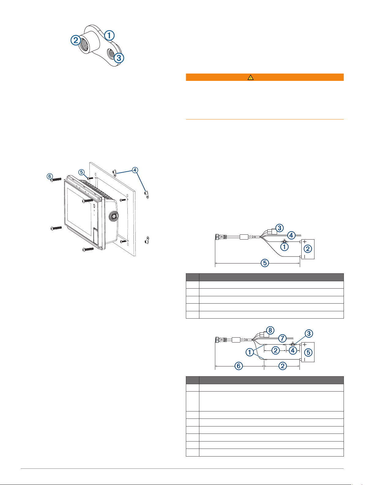
Item Description
Fuse
À
12 Vdc power source
Á
Command Link Plus® and Helm Master® bus network connector
Â
Differential NMEA® 0183 Connection Considerations, page 3
Ã
2.4 m (7.9 ft.) no extension
Ä
Item Description
Splice
À
• 10 AWG (5.26 mm²) extension wire, up to 4.6 m (15 ft.)
Á
• 8 AWG (8.36 mm²) extension wire, up to 7 m (23 ft.)
• 6 AWG (13.29 mm²) extension wire, up to 11 m (36 ft.)
Fuse
Â
20.3 cm (8 in.)
Ã
12 Vdc power source
Ä
2.4 m (7.9 ft.)
Å
Differential NMEA® 0183 Connection Considerations, page 3
Æ
Command Link Plus and Helm Master bus network connector
Ç
2
 Loading...