

Page 1
SERVICE MANUAL
PA
011523
HAMAMATSU, JAPAN
1.45K-9731 K Printed in Japan '00.07
CONTENTS
SPECIFICATIONS···································································· 3
PANEL LAYOUT······································································· 5
CIRCUIT BOARD LAYOUT······················································ 6
DIMENTIONS ··········································································· 8
BLOCK DIAGRAM···································································· 9
DISASSEMBLY PROCEDURE··············································· 10
LSI PIN DESCRIPTION·························································· 14
IC BLOCK DIAGRAM ····························································· 16
CIRCUIT BOARDS································································· 19
INSPECTION·········································································· 36
TEST PROGRAM··································································· 39
FLASH ROM UPGRADE························································ 43
ERROR MESSAGES······························································ 45
PARTS LIST
OVERALL CIRCUIT DIAGRAM
AD CONVERTER
200006**-150000
This document is printed on chlorine free (ECF) paper with soy ink.
Page 2
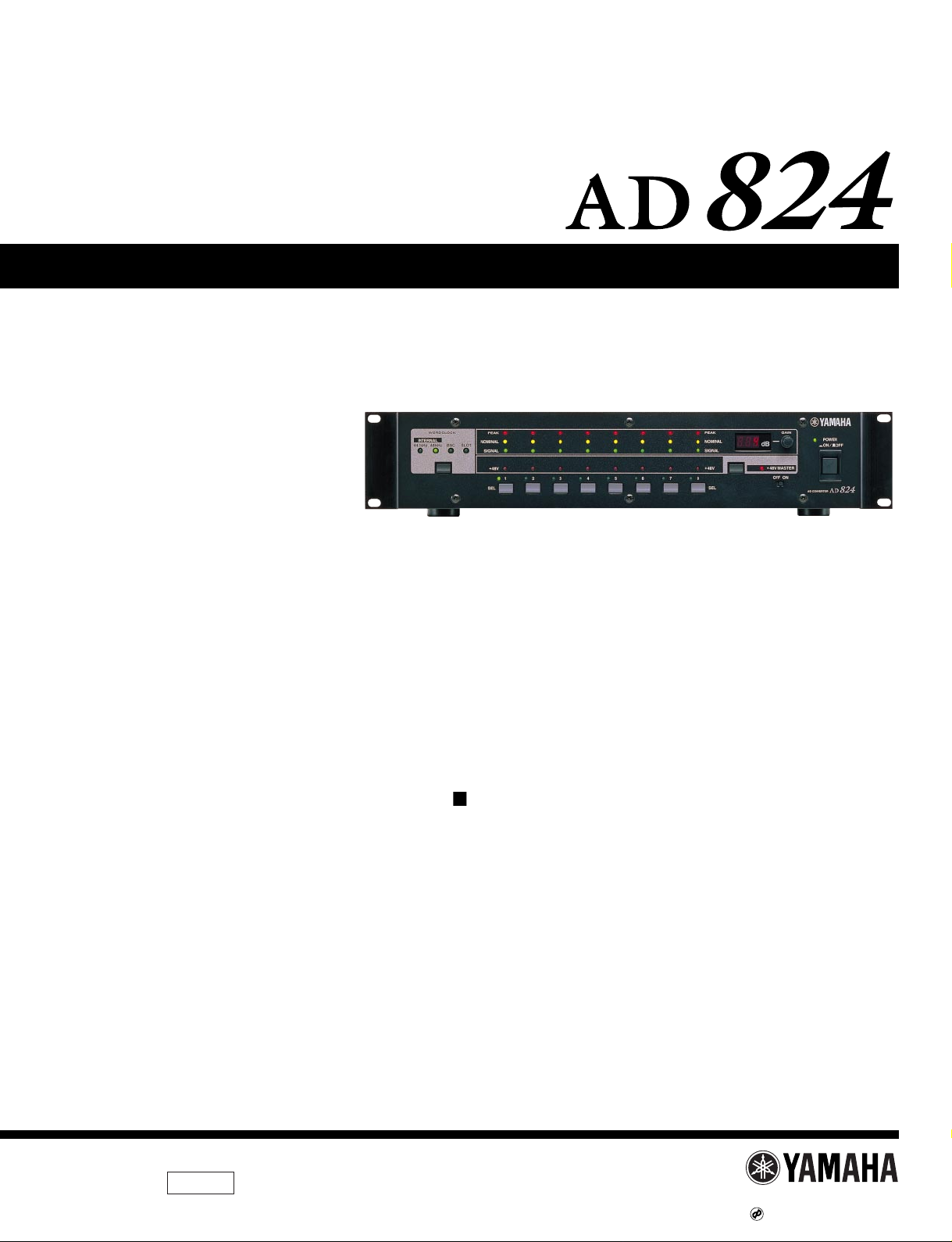
AD824
2
WARNING: CHEMICAL CONTENT NOTICE!
The solder used in the production of this product contains LEAD. In addition, other electrical/electronic and/or plastic (where
applicable) components may also contain traces of chemicals found by the California Health and Welfare Agency (and possibly
other entities) to cause cancer and/or birth defects or other reproductive harm.
DO NOT PLACE SOLDER, ELECTRICAL/ELECTRONIC OR PLASTIC COMPONENTS IN YOUR MOUTH FOR ANY REASON
WHAT SO EVER!
Avoid prolonged, unprotected contact between solder and your skin! When soldering, do not inhale solder fumes or expose eyes
to solder/flux vapor!
If you come in contact with solder or components located inside the enclosure of this product, wash your hands before handling
food.
IMPORTANT NOTICE
This manual has been provided for the use of authorized Yamaha Retailers and their service personnel. It has been assumed that
basic service procedures inherent to the industry, and more specifically Yamaha Products, are already known and understood by
the users, and have therefore not been restated.
WARNING: Failure to follow appropriate service and safety procedures when servicing this product may result in personal
injury, destruction of expensive components and failure of the product to perform as specified. For these
reasons, we advise all Yamaha product owners that all service required should be performed by an authorized
Yamaha Retailer or the appointed service representative.
IMPORTANT: This presentation or sale of this manual to any individual or firm does not constitute authorization, certification,
recognition of any applicable technical capabilities, or establish a principal-agent relationship of any form.
The data provided is belived to be accurate and applicable to the unit(s) indicated on the cover. The research engineering, and
service departments of Yamaha are continually striving to improve Yamaha products. Modifications are, therefore, inevitable and
changes in specification are subject to change without notice or obligation to retrofit. Should any discrepancy appear to exist,
please contact the distributor's Service Division.
WARNING: Static discharges can destroy expensive components. Discharge any static electricity your body may have
accumulated by grounding yourself to the ground bus in the unit (heavy gauge black wires connect to this bus).
IMPORTANT: Turn the unit OFF during disassembly and parts replacement. Recheck all work before you apply power to the
unit.
WARNING
Components having special characteristics are marked and must be replaced with parts having specification equal to those
originally installed.
LITHIUM BATTERY HANDLING
This product uses a lithium battery for memory back-up.
WARNING: Lithium batteries are dangerous because they can be exploded by improper handling. Observe the following
precautions when handling or replacing lithium batteries.
Leave lithium battery replacement to qualified service personnel.
Always replace with batteries of the same type.
When installing on the PC board by soldering, solder using the connection terminals provided on the battery cells.
Never solder directly to the cells. Perform the soldering as quickly as possible.
Never reverse the battery polarities when installing.
Do not short the batteries.
Do not attempt to recharge these batteries.
Do not disassemble the batteries.
Never heat batteries or throw them into fire.
ADVARSEL!
Lithiumbatteri-Eksplosionsfare ved fejlagtig håndtering. Udskiftning må kun ske med batteri af samme fabrikat og type. Levér det
brugte batteri tilbage til leverandøren.
VARNING
Explosionsfara vid felaktigt batteribyte.
Använd samma batterityp eller en ekvivalent typ som rekommenderas av apparattillverkaren.
Kassera använt batteri enligt fabrikantens instruktion.
VAROITUS
Paristo voi räjähtää, jos se on virheellisesti asennettu.
Vaihda paristo ainoastaan laitevalmistajan suosittelemaan tyyppiin.
Hävitä käytetty paristo valmistajan ohjeiden mukaisesti.
The following information complies with Dutch Official Gazette 1995. 45; ESSENTIALS OF ORDER ON THE COLLECTION OF
BATTERIES.
• Please refer to the diassembly procedure for the removal of Back-up Battery.
• Leest u voor het verwijderen van de backup batterij deze beschrijving.
Page 3
SPECIFICATIONS
AD824
3
IMPORTANT NOTICE FOR THE UNITED KINGDOM
Connecting the Plug and Cord
IMPORTANT. The wires in this main lead are coloured in
accordance with the following code:
BLUE: NEUTRAL
BROWN: LIVE
As the colours of the wires in the main lead of this apparatus may not
correspond with the coloured markings identifying the terminals in
your plug, proceed as follows:
The BLUE wire must be connected to the terminal that is marked with
the letter N (or coloured BLACK).
The BROWN wire must be connected to the terminal that is marked
with the letter L (or coloured RED).
Be certain that neither core is connected to the earth terminal of the
three pin plug.
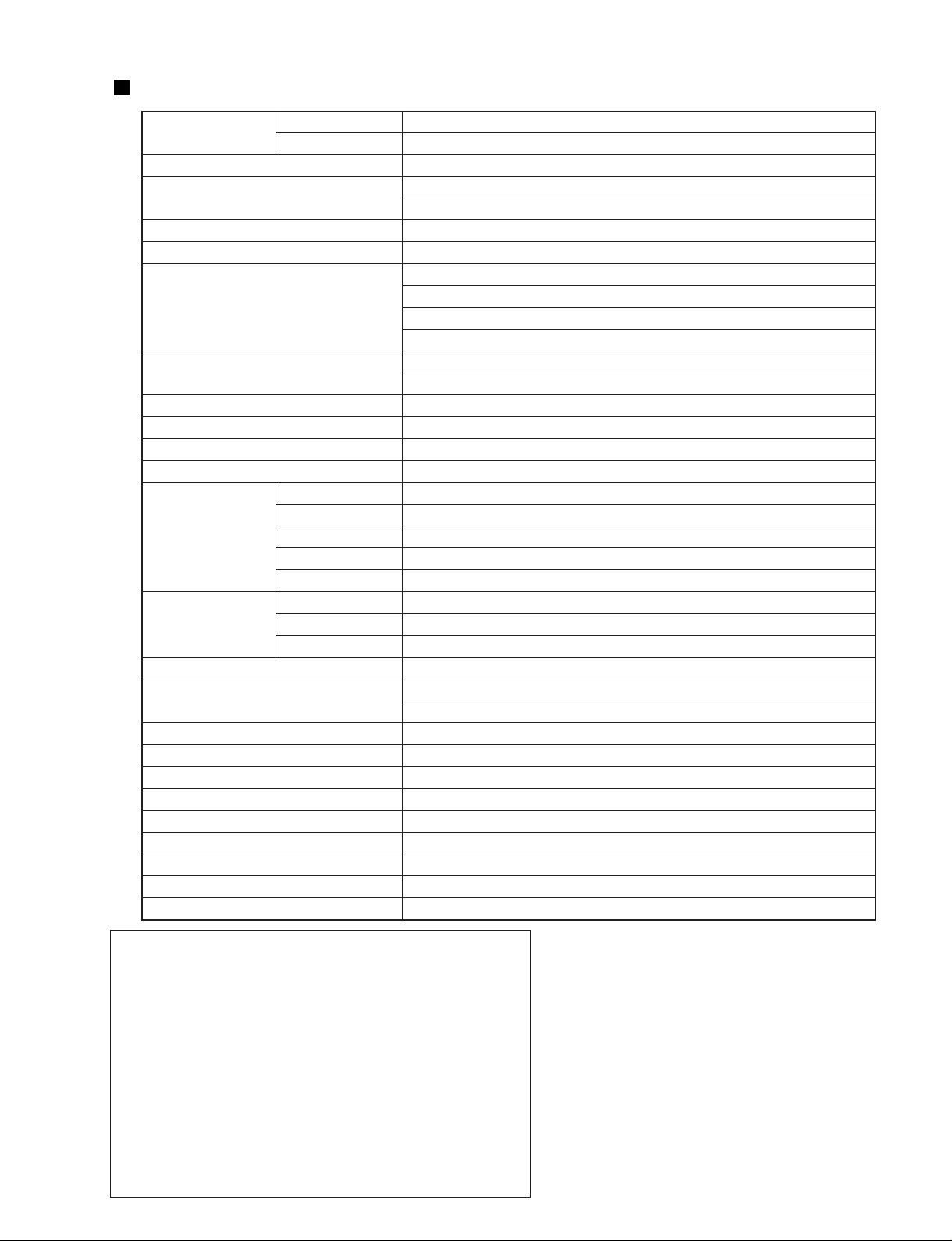
MY8-AE, MY8-TD
Sampling rate
MY8-AT
AD conversion resolution
Frequency response
Dynamic range *
1
Gain error
THD *
2
Hum & noise level *
1
Equivalent input noise *
1
Crosstalk
Signal delay
Phantom power
PEAK
NOMINAL
Channel indicators SIGNAL
+48 V
SEL
Wordclock
Other indicators +48 V MASTER
POWER
Gain display
Power requirements
Power consumption
Dimensions (W x H x D)
Weight
Free-air operating temperature
Storage temperature
Relative humidity
Power cord length
Supplied accessories
Options
39.69–50.88 kHz
41.013–50.88 kHz
24-bit linear, 128-times oversampling
-1.5, +1 dB, 20 Hz–20 kHz, GAIN +10 dB
-3, +1 dB, 20 Hz–20 kHz, GAIN -62 dB
110 dB (typical), GAIN +10 dB
±1 dB @ 1 kHz, GAIN -62 dB to +10 dB
0.1 %, 4 dB output @ 20 Hz–20 kHz, GAIN -62 dB
0.05 %, full scale output @ 1 kHz, GAIN -62 dB
0.05 %, 4 dB output @ 20 Hz–20 kHz, GAIN +10 dB
0.01 %, full scale output @ 1 kHz, GAIN +10 dB
-92 dB (typical), Rs = 150 Ω, GAIN +10 dB
-62 dB, Rs = 150 Ω, GAIN -62 dB
-128 dB, Rs = 150 Ω, GAIN -62 dB
-70 dB between adjacent channels @ 1 kHz
0.85 ms (analog input to digital output, fs = 48 kHz)
+48 V
3 dB below full scale
14 dB below full scale
34 dB below full scale
Phantom power on/off
Channel select
44.1kHz, 48kHz, BNC, SLOT
Phantom power master on/off
Power on/off
3-digit, 7-segment LED
U.S.A. & Canada 120 V AC, 60 Hz
Europe 230 V AC, 50 Hz
50 W
480 x 97.5 x 377.6 mm (18.9 x 3.84 x 14.86 inches)
8.5 kg (18.7 lbs)
10˚ C to 35˚ C (50˚ F to 95˚ F)
-20˚ C to 60˚ C (-4˚ F to 140˚ F)
10 %–95 %
1.9 m
Owner’s Manual, 9-pin D-sub crossed cable (1.5m)
MY8-AT, MY8-TD, MY8-AE mini YGDAI I/O cards
*1. Measured with a 6 dB/octave filter at 12.7 kHz;
equivalent to a 20 kHz filter with infinite dB/
octave attenuation.
*2. Measured with a 6 dB/octave filter @ 80 kHz.
* Where dB represents a specific voltage, 0 dB
is referenced to 0.775 V rms.
Page 4
AD824
4
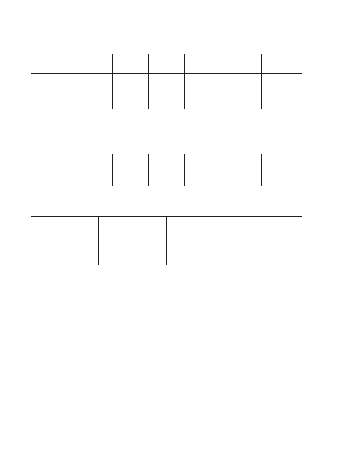
*1. 24-bit linear, 128-times oversampling A/D converters.
*2. XLR-type connectors are electronically balanced (pin 1 = ground, pin 2 = hot, pin 3 = cold).
*3. TRS phone jacks are electronically balanced (tip = hot, ring = cold, sleeve = ground).
* Where dB represents a specific voltage, 0 dB is referenced to 0.775 V rms.
Analog Input
Connection GAIN
Actual Load
Impedance
For Use
with
Nominal
Connector
Input Level
Nominal
Max.
before clip
INPUT 1–8 *
1
INSERT IN 1–8
3k Ω lines
10k W
50–600 Ω
mics &
600 Ω lines
600 Ω lines
-62 dB
+10 dB
-62 dB
(615 µV)
+10 dB
(2.45 V)
+10 dB
(2.45 V)
-48 dB
(3.08 mV)
+24 dB
(12.28 V)
+24 dB
(12.28 V)
XLR-3-31 type
(balanced)*
2
TRS phone jack
(balanced)*
3
*1. TRS phone jacks are electronically balanced (tip = hot, ring = cold, sleeve = ground).
* Where dB represents a specific voltage, 0 dB is referenced to 0.775 V rms.
Analog Output
Connection
Actual Source
Impedance
For Use
with
Nominal
Connector
Output Level
Nominal
Max.
before clip
INSERT OUT 1–8 150 Ω 10k Ω lines
+10 dB
(2.45 V)
+24 dB
(12.28 V)
TRS phone jack
(balanced)*
1
Digital I/O
Connection
COM PC/RS422
COM RS422
WORD CLOCK IN
WORD CLOCK OUT
SLOT
Format
—
—
—
—
mini YGDAI
Level/Impedance
RS232C/RS422
RS422
TTL, 75 Ω (ON/OFF)
TTL, 75 Ω
—
Connector
9-pin D-sub (male)
9-pin D-sub
BNC
BNC
—
Page 5
ON OFF
POWER
AD CONVERTER
12345678
PEAK
SIGNAL
NOMINAL
PEAK
SIGNAL
+48V
SEL
NOMINAL
+48V
WORD CLOCK
INTERNAL
44.1kHz BNC SLOT48kHz
SEL
dB
GAIN
OFF ON
+48V MASTER
INPUT
(BAL)
OUT
(BAL)
IN
(BAL)
INSERT
COM
AD824
8 2314567
8 3214567
8 4321567
SLOT
OUT
PC RS422
75 IN
ON
OFF
WORD CLOCK
RS422
1
6 7 8 9 10 11 12 13
15 16 17 18 19 20
22
21
23
24
14
2 3 4 5
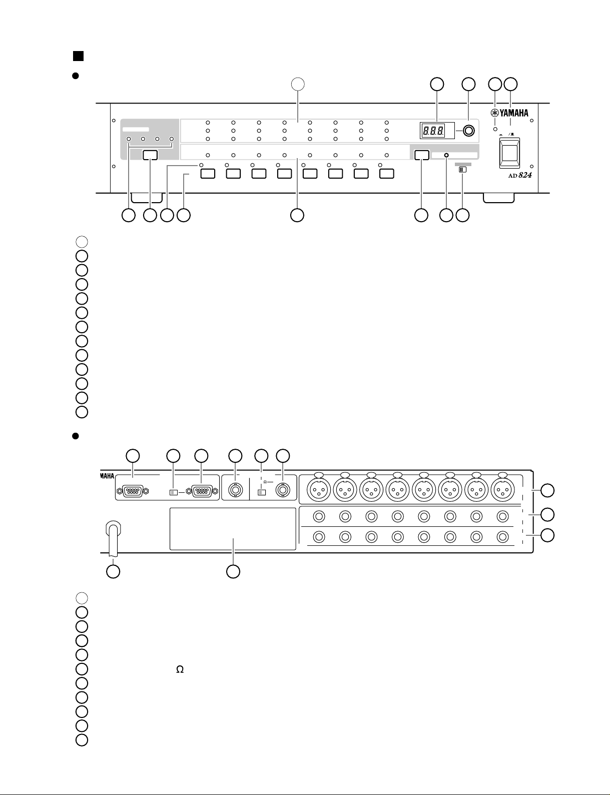
1
PEAK, NOMINAL & SIGNAL indicators
2
GAIN display
3
GAIN control
4
POWER indicator
5
POWER switch
6
WORD CLOCK indicators
7
WORD CLOCK Source button
8
Channel SEL indicators
9
Channel SEL buttons
10
Channel +48V indicators
11
+48V on/off button
12
+48V MASTER indicator
13
+48V MASTER switch
14
Power cable
15
16
COM RS422 port
COM PC/RS422 switch
17
COM PC/RS422 port
18
WORD CLOCK OUT connector
19
WORD CLOCK 75 ON/OFF switch
20
WORD CLOCK IN connector
21
INPUT (BAL) connectors
22
SLOT
23
INSERT OUT (BAL) connectors
24
INSERT IN (BAL) connectors
PANEL LAYOUT
AD824
5
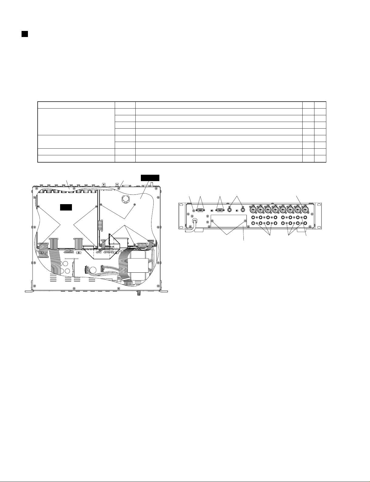
Front Panel
Rear Panel
VERTER
Page 6
AD824
6
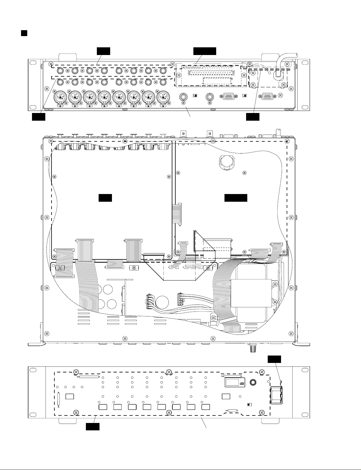
CIRCUIT BOARD LAYOUT
MAIN
MYSL
HA
JK
AD
AC
Rear panel assembly
Front panel assembly
Power transformer
PN
SW
CN909
CN903
CN906
CN902
CN904
CN905
CN901
CN908CN907
CN101 CN201
CN002
CN001
CN961
CN960
CN962
CN963
CN052 CN053
CN051
CN054
Page 7
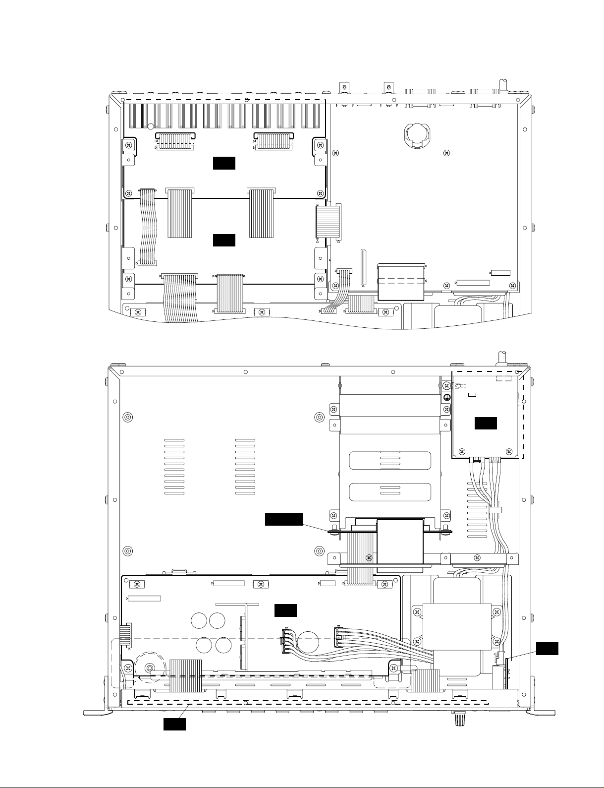
AD824
7
JK
AD
CN103
ADCN104
ADCN204
CN203
CN202CN102
CN005
CN004
CN002 CN001
CN003
CN004
CN001
CN003
MYSL
AC
DC
PN
SW
CN002
CN008CN010CN011
CN007
CN006
CN005
CN009
Page 8
AD824
8
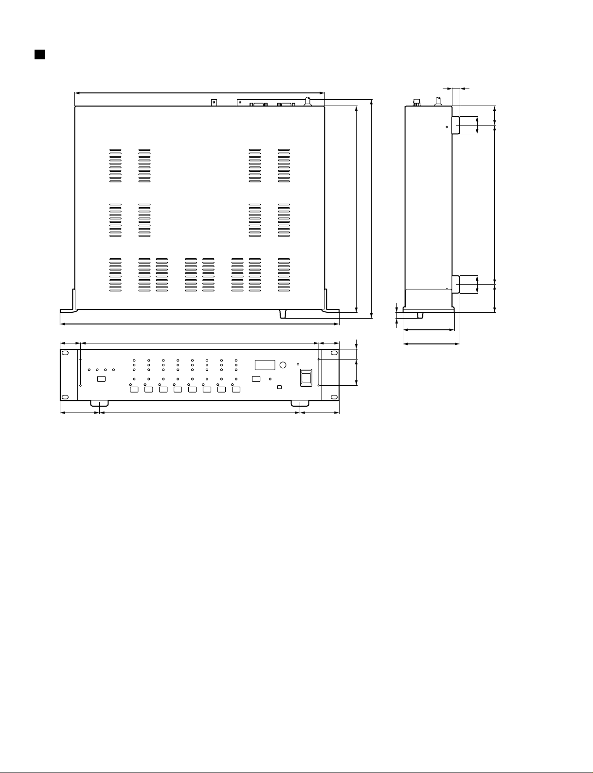
DIMENTIONS
67.5 67.5345
35 35410
430
13
88
H: 97.5
3030
48
(33)
274
10.8
45 17
355
D: 377.6
W: 480
Unit: mm
Page 9
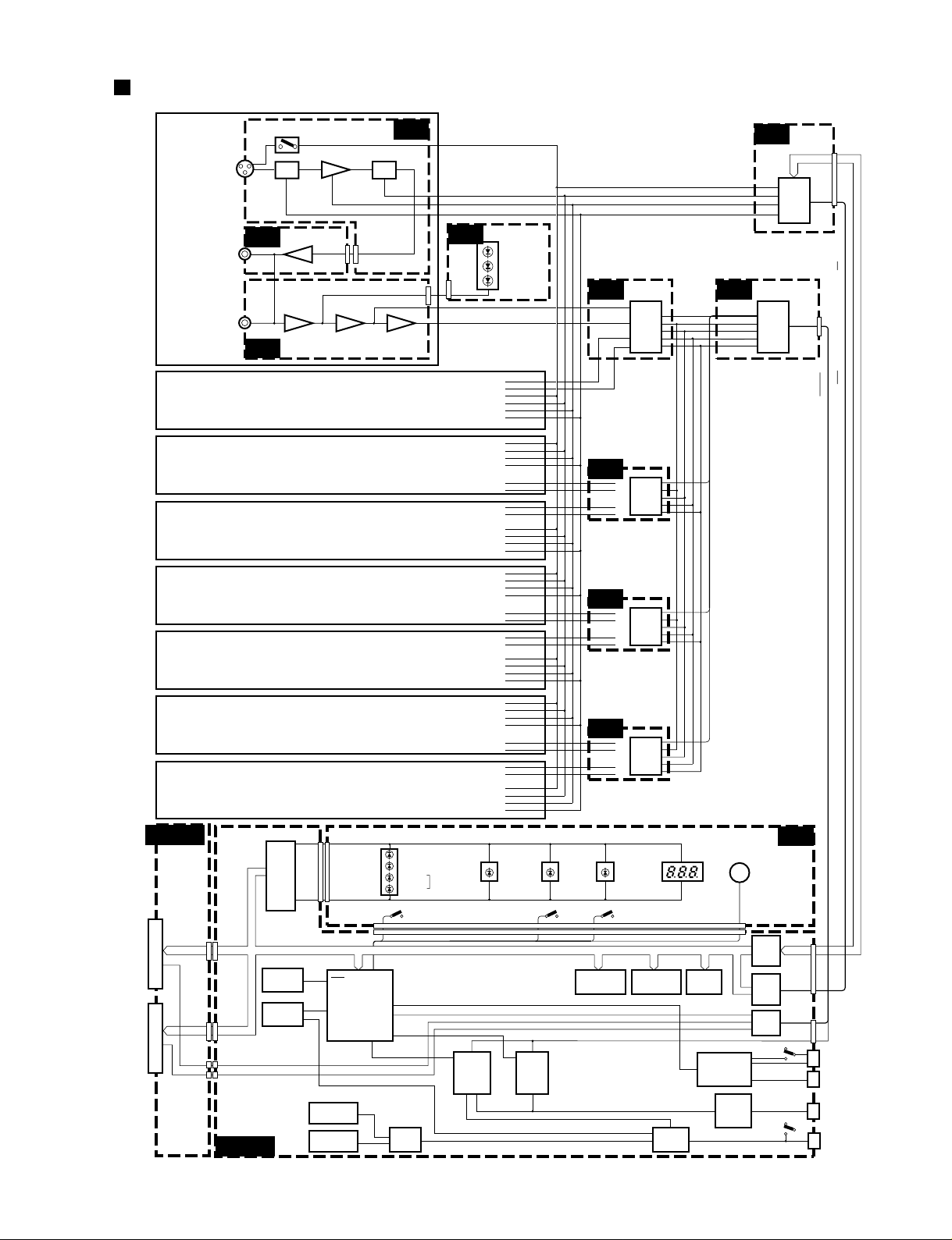
CH1
INPUT
JK101
INSERT OUT
JK102
CN002
CN101CN102
IC101
CN003
FS
SDATA
OUT1 ~ 8 , FS-AD , 64FS-AD , 256FS-AD , RESET-AD
64FS
256FS
RESET
CN002
CN962
LEVEL
PAD PAD
HA1 HA1
HA2A ,HA2B ,HA2C
+48V
Q102
RY101
IC101
IC102
PAD HA2
A / D
PERK
NOMINAL
SIGNAL
HA1
BA
INSERT IN
JK103
IC103
77 1
IC104
IC104
AINL+
AINL–
IC105
AK5342
BUFF
IC008
A / D
IC305
AK5342
AINR+
AINR–
CH2
CH3
CH4
D-FF
CH5
CH6
CH7
CH8
ADD-0~7
ADD-0~7
RST-HA , A1-HA , A2-HA , A3-HA , CS-HA
CPU
SH7042A
IC911
IC916
IC919
PE4
TX, RX
LOCK44
9.8304MHz
LOCK48
MUTE
COMA-TX, TX-COMB
256k SRAM
IC923
256k SRAM
IC924
8M ROM
IC927
BUFF
IC932
CN901CN054
CN051b
CN051a
CN901 OUT3/4,OUT7/8
OUT1/2,OUT5/6
CN904
CN905
CN961
SWA
SWA,SWB ECA,ECB+48
CN960
CN902CN053
CN902
CN053
CN054
BUFF
IC933
MUTE
PC/RS422
RS422
IC901
COM B/SLOT
SELECT
IC903
INT/EXT
SELECT
IC913
SELECT
IC910
D-FF
IC907
INT 48kHz
X902
INT 44.1kHz
X901
WORD
CLOCK
SELECT
IC921
PLL &
TIMING
GEN.
IC922
CN903
CN909
PC
ON
OFF
RS422
EXT-DIRIN
XI
CN907
CN908
RESET
SLOT
SLOT
D-FF
D-FF
RES
EXTAL
44.1kHz
48kHz
BNC
SLOT
WORD CLOCK
INTERNAL
+48V x 8
SEL x 8
SEL1~8
+48V
MASTER
Rotary Encoder
GAIN
dB
OUT
IN
JK902
JK901
MAIN
MYSL
HA
HA
AD
AD
A / D
IC505
AK5342
AD
A / D
IC705
AK5342
AD
PN
AD
PN
JK
AD
COM
WORD CLOCK
KEC-92536
IC001
–006
4
15–18
6
7
9
8
5
25
24
EC960
IC928,
929
84
74
87
9
5
47,48
90
88
15
15
12
3
11 3,9
36 36
56
5,6
19
3,5
9,15
2,4
3,4
7
7
11
SW901
BLOCK DIAGRAM
AD824
9
Page 10
HA
<Top View>
Top cover
IF plate
[460]
[530]
[300] [450] X16[290]
[A]
[500] X14
[310]
[500]: Bind Head Tapping Screw-B A4.0X8 MFZN2BL (VC688800)
Fig. 1
<Rear View>
[330]: Bonding Tapping Screw-B 3.0X8 MFZN2BL (VN413300)
[390]: Bonding Tapping Screw-B 3.0X8 MFZN2BL (VN413300)
[530]: Bind Head Screw A4.0X12 MFZN2BL (VP156900)
Fig. 2
[A]
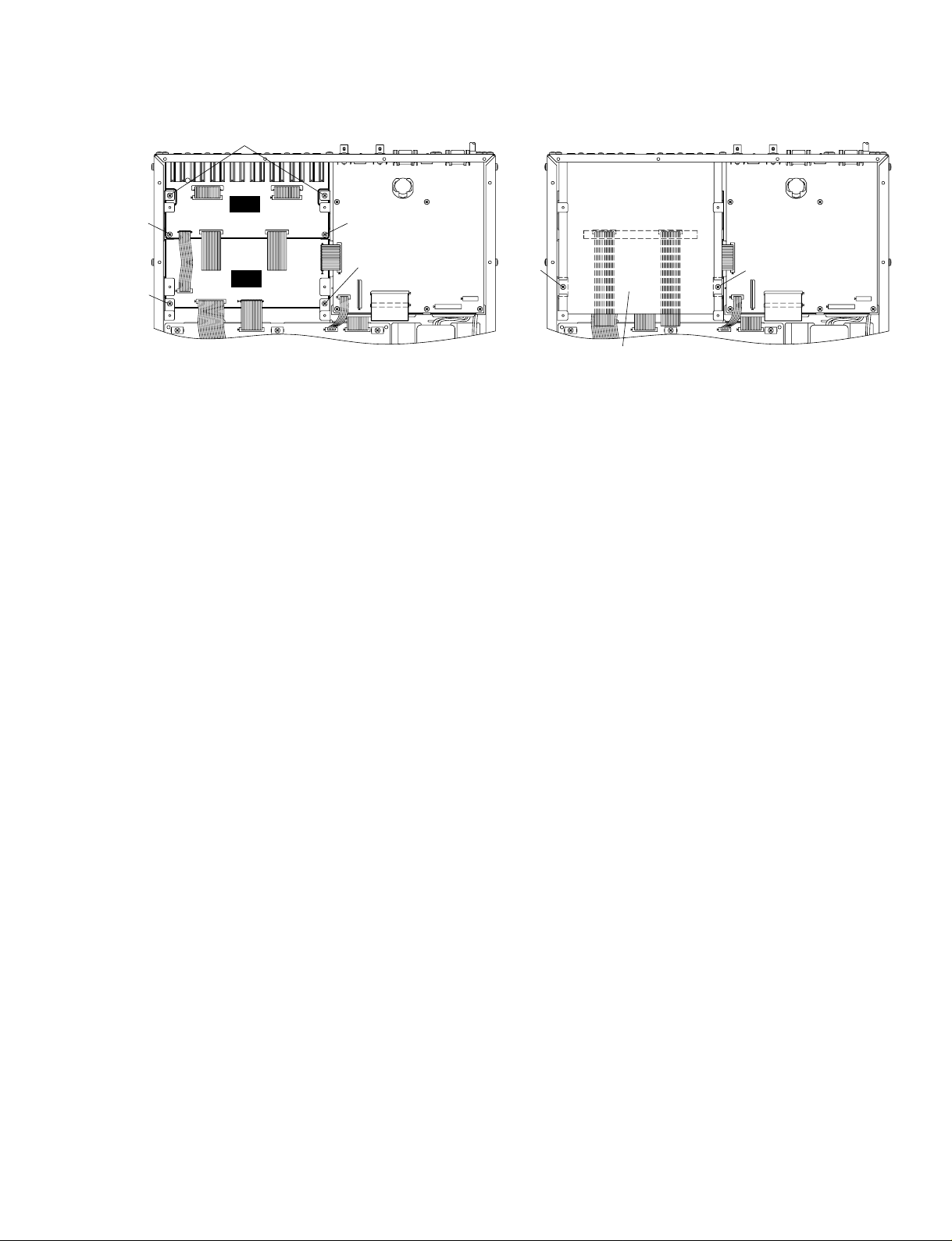
MAIN
[390]X6[330][330]
3. JK Circuit Board and AD Circuit Board
3-1 Remove the top cover. (See procedure 1.)
3-2 Remove the HA circuit board. (See procedure 2.)
3-3 Remove the two (2) screws marked [430]. The AD shield
sheet can then be removed. (Fig. 4)
3-4 Remove the six (6) screws marked [390] and the two (2)
screws marked [400]. The JK circuit board can then be
removed. (Fig. 2 and Fig. 3)
4. AD Circuit Board
4-1 Remove the top cover. (See procedure 1.)
4-2 Remove the HA circuit board. (See procedure 2.)
4-3 Remove the JK circuit board. (See procedure 3.)
4-4 Remove the six (6) screws marked [330], the two (2)
screws marked [350] and the two (2) screws marked
[370]. The AD circuit board can then be removed. (Fig. 2
and Fig. 3)
AD824
10
DISASSEMBLY PROCEDURE
1. Top Cover
1-1 Remove the fourteen (14) screws marked [500]. The top
cover can then be removed. (Fig. 1)
2. Circuit Boards and Units
Remove the top cover, each circuit board and unit can
then be removed.
Circuit Board and Unit
MAIN
HA
DC Assembly
Power Transformer
A
290
300
310
450
460
210
190
Screw
Bonding Screw 4.0X8 MFZN2BL (VS154500)
Bonding Screw 3.0X6 MFZN2BL (VS863000)
Bind Head Tapping Screw-B 3.0X6 MFZN2BL (EP600230)
Bonding Tapping Screw 3.0X8 MFZN2BL (VN41330)
Bind Head Tapping Screw-B 3.0X6 MFZN2BL (EP600230)
Bind Head Tapping Screw-B A4.0X6 MFZN2BL (VC688800)
Bind Head Tapping Screw-B A4.0X6 MFZN2BL (VC688800)
4
1
2
5
16
4
2
4
Ref. No. Screw QTY
2
2
2
1
2
1
5
5
Fig.
Page 11
AD824
11
<Top View>
[400]
[350]
[370]
[370]
JK
AD
[350]: Bonding Tapping Screw-B 3.0X8 MFZN2BL (VN413300)
[370]: Bonding Tapping Screw-B 3.0X8 MFZN2BL (VN413300)
[400]: Bind Head Tapping Screw-B 3.0X6 MFZN2BL (EP600230)
[430]: Bind Head Tapping Screw-B 3.0X6 MFZN2BL (EP600230)
Fig. 3 Fig. 4
<Top View>
[400]
[430] [430]
AD shield sheet
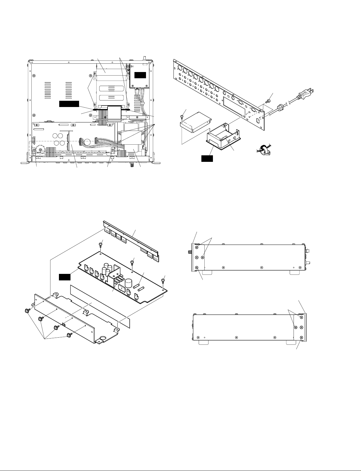
5. MYSL Circuit Board
* Note that remove card before following operation.
5-1 Remove the top cover. (See procedure 1.)
5-2 Remove the MAIN circuit board. (See procedure 2.)
5-3 Remove the two (2) screws marked [530]. The IF plate
can then be removed. (Fig. 2)
5-4 Remove the four (4) screws marked [260]. The OPT
assembly can then be removed. (Fig. 5)
5-5 Remove the two (2) screws marked [240]. The MYSL
circuit board can then be removed. (Fig. 5)
6. AC Circuit Board
6-1 Remove the top cover. (See procedure 1.)
6-2 Remove the MAIN circuit board. (See procedure 2.)
6-3 Remove the three (3) screws marked [50A] and the two
(2) screws marked [110A]. The AC circuit board can then
be removed. (Fig. 6)
* The fuse is not a part of the AC circuit Board. When you
replace the AC circuit board, you should remove the fuse
from the board, and put it back into the holder on the new
board.
7. DC Circuit Board
7-1 Remove the top cover. (See procedure 1.)
7-2 Remove the DC assembly. (See procedure 2.)
7-3 Remove the four (4) screws marked [60]. The transistor
holder can then be removed. (Fig. 7)
7-4 Remove the three (3) screws marked [40]. The DC circuit
board can then be removed. (Fig. 7)
* The four fuses are not part of the DC circuit Board. When
you replace the DC circuit board, you should remove the
fuses from the board, and put it back into the holder on the
new board.
Page 12
[60]
[140]
[140]
[140]
DC
[40]: Bonding Tapping Screw-B 3.0X8 MFZN2BL (VN413300)
[60]: Pan Head Screw SP4.0X8 MFZN2Y (EL200020)
Fig. 7
[140]: Oval Head Screw B4.0X10 MFZN2BL (V6221000)
Fig. 8
• DC Assembly
[40]
[40]
[40]
Transistor holder
Rack mount angle
Rack mount angle
<Right View>
<Left View>
[140]
Fuses
Fuses
AD824
12
8. PN Circuit Board and SW Circuit Board
8-1 Remove the top cover. (See procedure 1.)
8-2 Remove the six (6) screws marked [140]. The right and
left rack mount angles can then be removed. (Fig. 8)
8-3 Remove the knob marked [110B]. (Fig. 9)
8-4 Remove the six (6) screws marked [80]. The front panel
can then be removed. (Fig. 9)
AC
[250]: Bind Head Screw 4.0X8 MFZN2BL (EG340360)
[260]: Bonding Tapping Screw-B 3.0X8 MFZN2BL (VN413300)
Fig. 5
<Top View>
DC assembly
OPT assembly
MYSL
Power transformer
[190]
[260]
[260]
[210]
[250]
[250]
[210]
[110A] X2
Fuse
AC
[50A]: Bind Head Tapping Screw-B A4.0X8 MFZN2BL (VC688800)
[110A]: Bonding Tapping Screw-B 3.0X8 MFZN2BL (VN413300)
Fig. 6
• Rear Panel Assembly
[50A] X3
Page 13
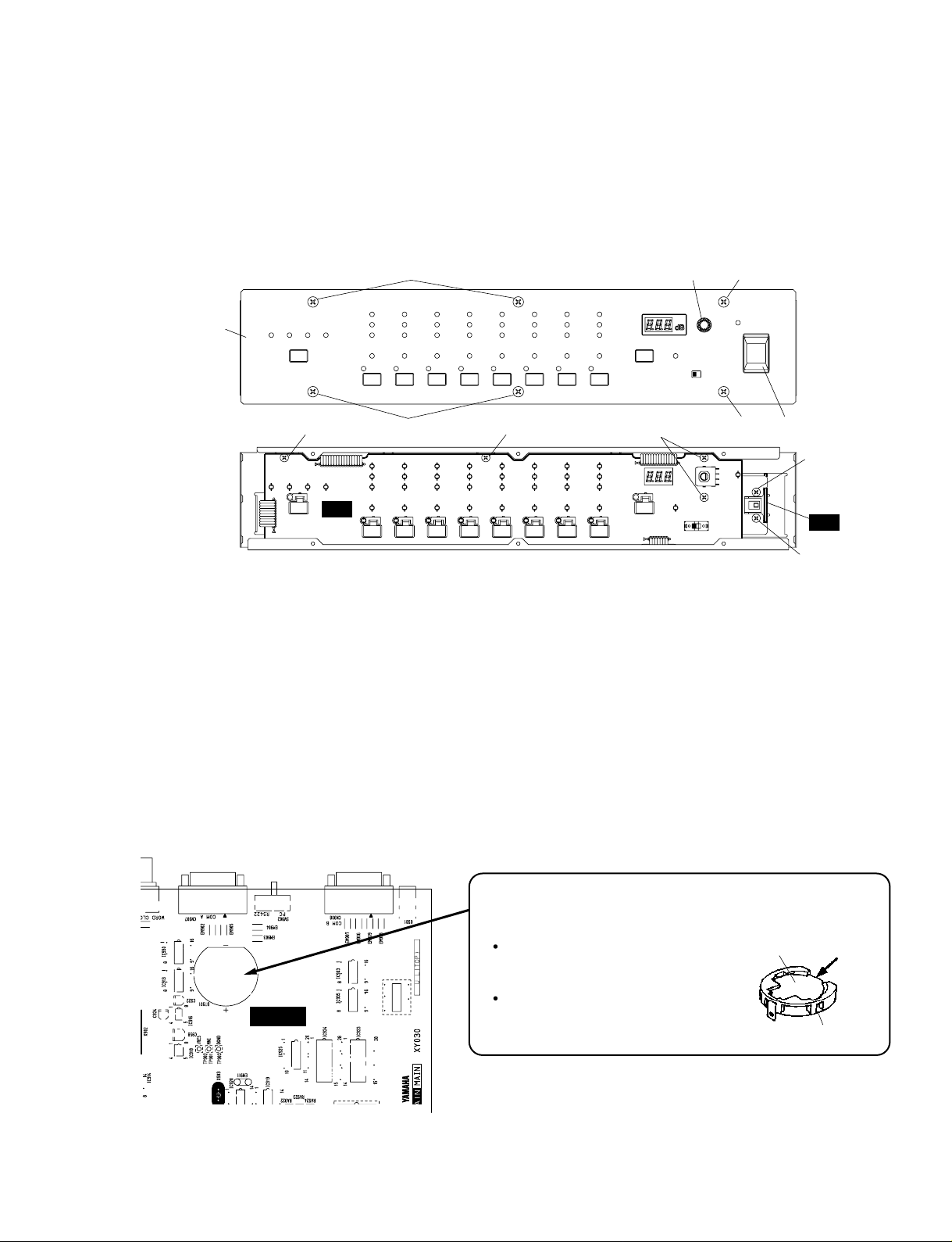
Fig. 10
Battery VN103500
VN103600(Battery holder for VN103500)
Notice for back-up battery removal
Push the battery as shown in figure,
then the battery will pop up.
Druk de batterij naar beneden zoals
aangeven in de tekening, de batterij
springt dan naar voren.
Battery
Battery holder
MAIN
[80]
PN
SW
[80]: Oval Head Screw 4.0X8 MFZN2BL (VS153600)
Fig. 9
[30]: Bind Head Tapping Screw-B 3.0X6 MFZN2BL (EP600230)
[50B]: Bonding Screw 3.0X6 MFZN2BL (VS863000)
<Front View>
[80]
[30]
[50B]
[50B]
[30]
[80][80] [110B]
[90]
Front panel
[30]
AD824
13
8-5 PN Circuit Board:
Remove the four (4) screws marked [30]. The PN circuit
board can then be removed. (Fig. 9)
8-6 SW Circuit Board:
Remove the PSW knob marked [90]. (Fig. 9)
Remove the two (2) screws marked [50B]. The SW circuit
board can then be removed. (Fig. 9)
9. Replacement of the Lithium Battery
9-1 Remove the top cover. (See procedure 1.)
9-2 Remove the MAIN circuit board. (See procedure 2.)
9-3 The lithium battery can be replacement on the MAIN
circuit board. (Fig. 10)
* The lithium battery is not a part of the MAIN circuit
board. When you replace the MAIN circuit board, remove
the lithium battery and install it in the new circuit board.
Page 14
AD824
14
LSI PIN DESCRIPTION
PIN
NO.
I/O FUNCTIONNAME
PIN
NO.
I/O FUNCTIONNAME
1
2
3
4
5
6
7
8
9
10
11
12
13
14
15
16
17
18
19
20
21
22
DAUX
HDLT
DOUT
VFL
OPT
SYNC
MCC
WC
MCB
MCA
SKSY
XI
XO
P256
LOCK
Vss
TC
DIM1
DIM0
DOM1
DOM0
KM1
I
O
O
O
O
O
O
O
O
O
I
I
O
O
O
O
I
I
I
I
I
Auxiliary input for audio data
Asynchronous buffer operation flag
Audio data output
Parity flag output
Fs x 1 Synchronous output signal for DAC
Fs x 1 Synchronous output signal for DSP
Fs x 64 Bit clock output
Fs x 1 Word clock output
Fs x 128 Bit clock output
Fs x 256 Bit clock output
Clock synchronization control input
Crystal oscillator connection or external
clock input
Crystal oscillator connection
VCO oscillating clock connection
PLL lock flag
Logic section power (GND)
PLL time constant switching output
Data input mode selection
Data input mode selection
Data output mode selection
Data output mode selection
Clock mode switching input 1
23
24
25
26
27
28
29
30
31
32
33
34
35
36
37
38
39
40
41
42
43
44
RSTN
Vdda
CTLN
PCO
(NC)
CTLP
Vssa
TSTN
KM2
KM0
FS1
FS0
CSM
EXTW
DDIN
LR
Vdd
ERR
EMP
CD0
CCK
CLD
I
I
O
I
I
I
I
O
O
I
I
I
O
O
O
O
I
I
System reset input
VCO section power (+5 V)
VCO control input N
PLL phase comparison output
VCO control input P
VCO section power (GND)
Test terminal. Open for normal use
Clock mode switching input 2
Clock mode switching input 0
Channel status sampling frequency
display output 1
Channel status sampling frequency
display output 0
Channel status output method selection
External synchronous auxiliary input
word clock
EIAJ (AES/EBU) data input
PLL word clock output
Logic section power (+5 V)
Data error flag output
Channel status emphasis control code
output
3-wire type microcomputer interface data
output
3-wire type microcomputer interface clock
input
3-wire type microcomputer interface load
input
YM3436DK (XG948E0) DIR2 (Digital Format Interface Receiver)
MAIN: IC921, 922
PIN
NO.
I/O FUNCTIONNAME
PIN
NO.
I/O FUNCTIONNAME
1
2
3
4
5
6
7
8
9
10
11
12
13
14
VREFL
GNDL
VCOML
AINL+
AINLZCAL
VD
DGND
CAL
/RST
SMODE2
SMODE1
LRCK
SCLK
O
-
O
I
I
-
-
O
I
I
I
I/O
I/O
L ch standard voltage output (+3.75 V)
L ch Ground
L ch common voltage (+2.5 V)
L ch analog (+) input
L ch analog (-) input
Zero calibration
“L”: VCOML,VCOMR
“H”: Analog input (AINL+/-,AINRR+/-)
Power supply for digital
Ground for digital
Calibration status
Reset
Serial interface mode select
MSB first, 2’s compliment
L/R ch select clock
Serial data clock
15
16
17
18
19
20
21
22
23
24
25
26
27
28
SDATA
FSYNC
MCLK
CMODE
HPFE
TEST
BGND
AGND
VA
AINR-
AINR+
VCOMR
GNDR
VREFR
O
I/O
I
I
I
I
-
-
I
I
O
-
O
Serial data output
Frame synchronization clock
Master clock input
CMODE=“H”:384 fs
CMODE=“L”:256 fs
Master clock select
“L”: MCLK=256 fs (12.288 MHz @fs=48 kHz)
“H”: MCLK=384 fs (18.432 MHz @fs=48 kHz)
HPF enable “L”: OFF “H”: ON
TEST pin
Connect it with DGND.
Ground
Ground for analog
Power supply for analog (+5 V)
R ch analog (+) input
R ch analog (-) input
R ch common voltage (-2.5 V)
R ch ground
R ch standard voltage output (+3.75 V)
AK5392-VS-E2 (XV065A00) ADC (Analog to Digital Converter)
SMODE2
L
L
H
H
SMODE1
L
H
L
H
MODE
Slave mode
Master mode
Slave mode
Master mode
LRCK
H/L
H/L
L/H
L/H
AD: IC105, 305, 505, 705
Page 15
AD824
15
PIN
NO.
I/O FUNCTIONNAME
PIN
NO.
I/O FUNCTIONNAME
1
2
3
4
5
6
7
8
9
10
11
12
13
14
15
16
17
18
19
20
21
22
23
24
25
26
27
28
29
30
31
32
33
34
35
36
37
38
39
40
41
42
43
44
45
46
47
48
49
50
51
52
53
54
55
56
PE14
PE15
VSS
A0
A1
A2
A3
A4
A5
A6
A7
A8
A9
A10
A11
A12
A13
A14
A15
A16
VCC
A17
VSS
/RAS
/CASL
/CASH
VSS
RDWR / PB5
A18
A19
A20
PB9 /A21
VSS
/RD
/WDTOVF
/WRH
VCC
/WRL
VSS
/CS1
/CS0
PA9 / TCLKD
/IRQ2 / TCLKC
/CS3
/CS2
/IRQ1
TXD
RXD
/IRQ0
PA1 / TXD0
PA0 / RXD0
D15
D14
D13
VSS
D12
O
O
I
O
O
O
O
O
O
O
O
O
O
O
O
O
O
O
O
O
I
O
I
O
O
O
O
O
O
O
O
O
I
O
O
O
I
O
I
O
O
O
I
O
O
I
O
I
I
O
I
I/O
I/O
I/O
I
I/O
Port E
Port E
Ground
Address bus
Power supply
Address bus
Ground
Row address strobe
Column address strobe (low)
Column address strobe (high)
Ground
DRAM read/write / Port B
Address bus
Port B / Address bus
Ground
Read
Watch dog timer overflow
High write
Power supply
Low write
Ground
Chip select
Chip select
Port A / Timer clock
Interrupt request / Timer clock
Chip select
Chip select
Interrupt request
Data transmission
Data reception
Interrupt request
Port A / Data transmission
Port A / Data reception
Data bus
Ground
Data bus
57
58
59
60
61
62
63
64
65
66
67
68
69
70
71
72
73
74
75
76
77
78
79
80
81
82
83
84
85
86
87
88
89
90
91
92
93
94
95
96
97
98
99
100
101
102
103
104
105
106
107
108
109
110
111
112
D11
D10
D9
D8
VSS
D7
D6
D5
VCC
D4
D3
D2
D1
D0
VSS
XTAL
MD3
EXTAL
MD2
NMI
VCC
MD1
MD0
PLLVCC
PLLCAP
PLLVSS
PA15 / CK
/RES
PE0
PE1
PE2
PE3
PE4
VSS
AN0 / PF0
AN1 / PF1
AN2 / PF2
AN3 / PF3
AN4 / PF4
AN5 / PF5
AVSS
AN6 / PF6
AN7 / PF7
AVCC
VSS
PE5
VCC
PE6
PE7
PE8
PE9
PE10
VSS
PE11
PE12
PE13
I/O
I/O
I/O
I/O
I
I/O
I/O
I/O
I
I/O
I/O
I/O
I/O
I/O
I
I
I
I
I
I
I
I
I
I
I
I
O
I
I
I
I
I
I
I
I
I
I
I
I
I
I
I
I
I
I
O
I
O
O
O
O
O
I
O
O
O
Data bus
Ground
Data bus
Power supply
Data bus
Ground
Crystal oscillator
Mode control
Crystal oscillator
Mode control
Non-maskable interrupt request
Power supply
Mode control
Mode control
PLL Power supply
PLL capacitor
PLL Ground
Port A / Clock
Reset
Port E
Ground
Analog input / Port F
Analog ground
Analog input / Port F
Analog input / Port F
Power supply
Ground
Port E
Power supply
Port E
Ground
Port E
HD6477042AF28 (XV731A00) CPU MAIN: IC911
Page 16
AD824
16
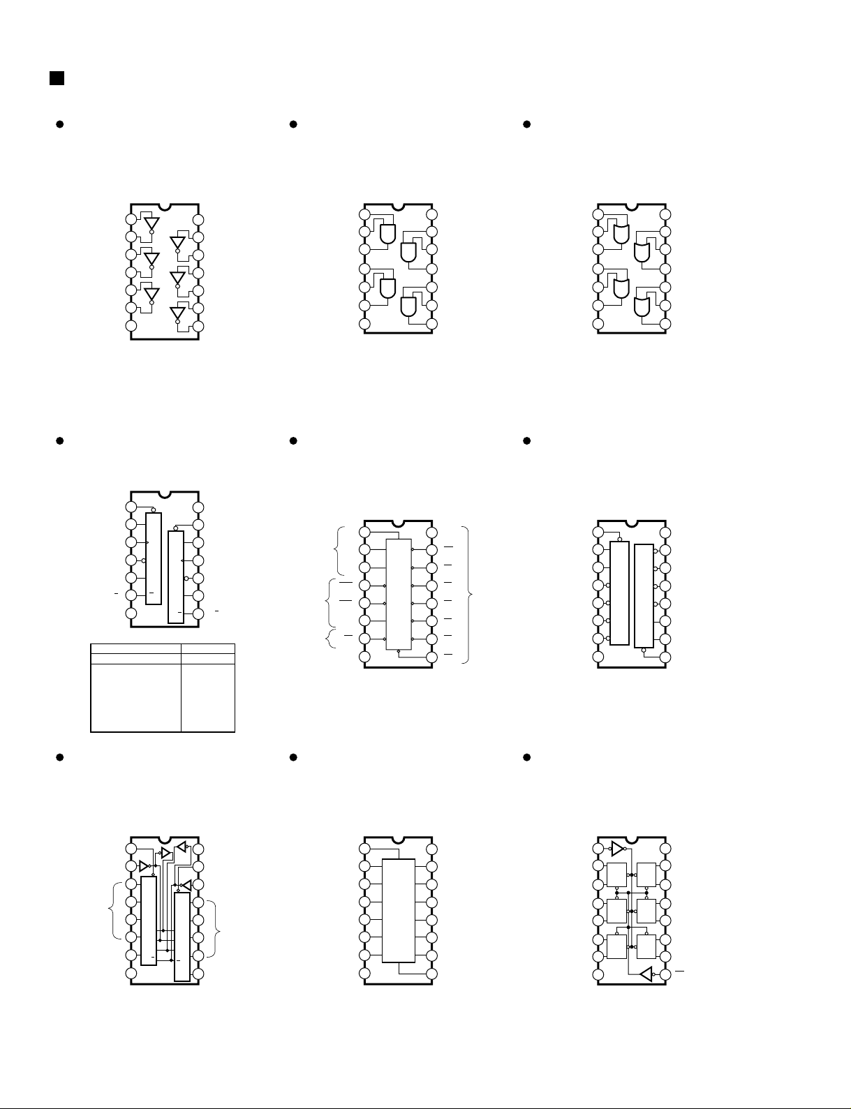
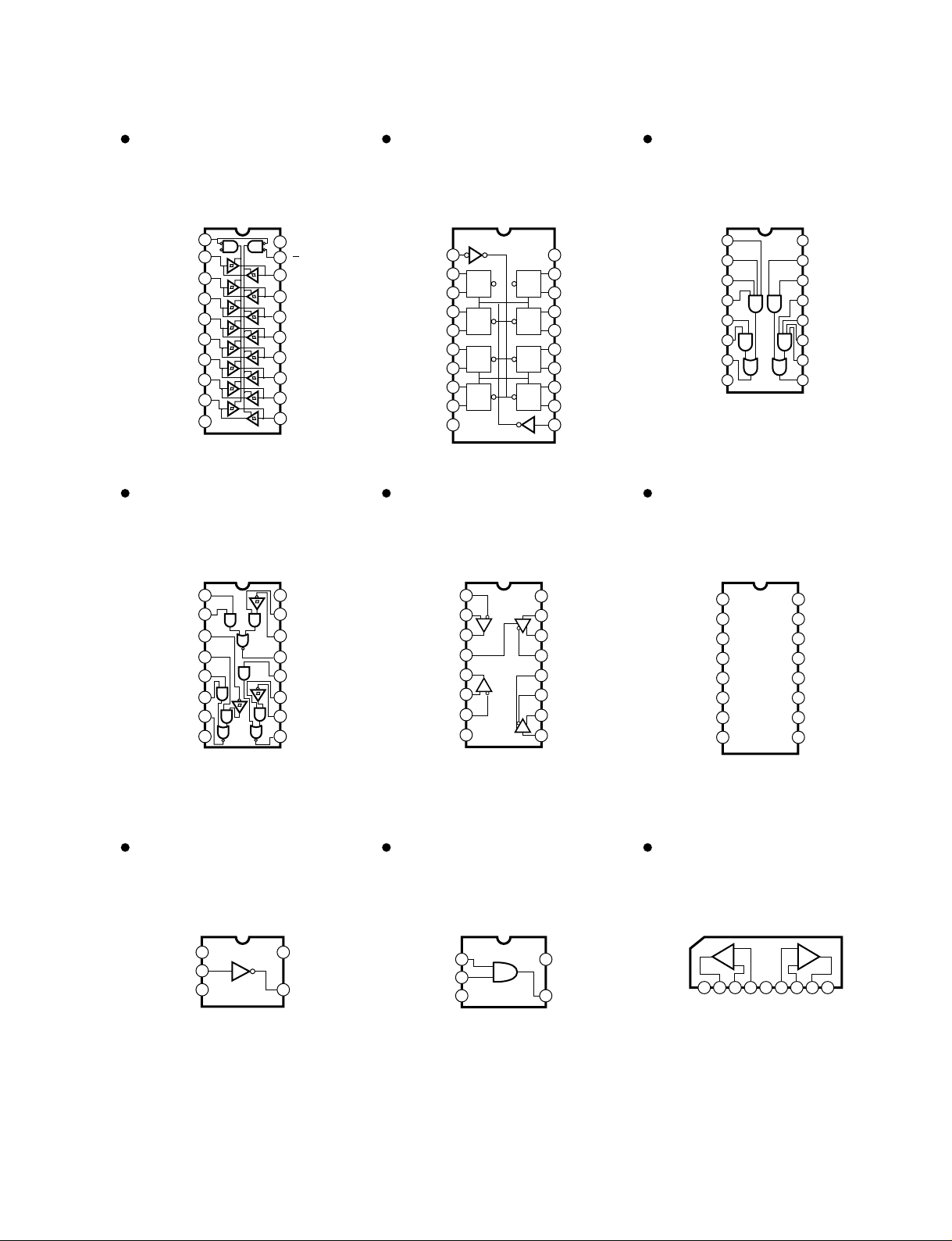
IC BLOCK DIAGRAM
HD74LV04AFPEL (IS000400)
HD74LVU04AFPEL (XY102A00)
Hex Inverter
MAIN: IC914,920
HD74LV08AFPEL (IS000800)
Quad 2 Input AND
MAIN: IC912
HD74LV32AFPEL (IS003200)
Quad 2 Input OR
MAIN: IC926
HD74LV74AFPEL (IS007400)
Dual D-Type Flip-Flop
MAIN: IC907,919
SN74LV138ANSR (IS013810)
SN74LV138AFPEL (IS013800)
3 to 8 Demultiplexer
MAIN:
HA:
SN74LV139ANSR (IS013910)
Dual 2 to 4 Demultiplexer
MAIN: IC915
TC74HC153AFEL (XY309A00)
Dual 4 to 1 Data Selectors
MAIN: IC910,913
HD74LV157AFPEL (IS015700)
Quad 2 to 1 Multiplexer
MAIN: IC935
SN74LV174ANSR (IS0174100)
Hex D-Type Flip-Flop
MAIN: IC929
1
2
3
4
5
6
7
1A
1Y
2A
2Y
3A
3Y
Vss
14
13
12
11
10
9
8
VDD
6A
6Y
5A
5Y
4A
4Y
1
2
3
1A
1Y
42A
52B
62Y
7
VSS
1B
14
13
12
VDD
4A
11 4Y
10 3B
9 3A
8 3Y
4B
1
2
3
1A
1Y
42A
52B
62Y
7GND
1B
14
13
12
Vcc
4A
11 4Y
10 3B
9 3A
8 3Y
4B
INPUTS OUTPUTS
PR CLR CLK D Q Q
L
H
H
L
H
Q
O
H
L
H
H
L
Q O
X
X
X
H
L
X
X
X
X
f
f
L
H
L
L
H
H
H
L
H
L
H
H
H
1
2
3
4
5
6
7
1CLR
1D
1CK
1PR
1Q
1Q
GND
14
13
12
11
10
9
8
VCC
2CLR
CLR
2D
D
2CK
CK
2PRPR
2Q
2Q
Q
Q
CLR
D
CK
PR
Q
Q
IC917
IC009
1
2
3
4
5
6
7
A
A
Select
Enable
Output
Output
B
B
C
C
G2A
G2A
G2B
G2B
G1
G1
Y7
Y7 Y5
Y4
Y3
Y2
Y1
Y0
Y6
16
15
14
13
12
11
10
Vcc
YO
Y1
Y2
Y3
Y4
Y5
8
GND
9
Y6
1
2
3
4
5
6
7
1G
1A
1B
1Y0
1Y1
1Y2
1Y3
A
G
B
Y0
Y1
Y2
Y3
16
15
14
13
12
11
10
Vcc
2G
2A
2B
2Y0
2Y1
2Y2
8
GND
9
2Y3
Y2
Y3
Y1
Y0
B
A
G
1
2
3
4
5
6
7
1G SELECT
STROBE B
OUTPUT 1Y
1G
IC3
IC2
IC1
IC0
1Y
16
15
14
13
12
11
10
Vcc
SELECT 2G
STROBE A
8
GND
9
OUTPUT 2Y
2C0
2Y
2C1
2C2
2C3
2G
B
B
B
B
A
A
A
A
DATA
INPUTS
DATA
INPUTS
1
2
3
4
5
6
7
SELECT
1A
1A
1B
1B
1Y
1Y
2A
2A
2B
2B
2Y
2Y
16
15
14
13
12
11
10
Vcc
STROBE
G
4A
S3Y
4A
4B
4B
4Y
4Y
3A
3A
3B
3B
8
GND
9
3Y
Q
Q
DC K C K
C K
DC K
GG
CLEAR
1Q
1D
2D
2Q
3D
3Q
GND
1 16
2 15
3 14
4 13
5 12
6 11
7 10
8 9
Vcc
6Q
6D
5D
5Q
4D
4Q
CK
Q
D
GG
Q
DC K
G
C K
Q
D
G
Q
D
Page 17
AD824
17
HD74LV245AFPEL (IS024500)
Octal 3-State Bus Transceiver
MAIN:
AD:
HA:
HD74LV273AFPEL (IS027300)
Octal D-Type Flir Flop
MAIN:
HA:
SN75121NSR (XU816A00)
Dual Line Driver
MAIN: IC930
SN75124NS (XN976A00)
Triple Line Receiver
MAIN: IC902
SN75C1168NSR (XU073A00)
Line Driver / Receiver
MAIN: IC903
HD74HC4053AF(EL) (XY879A00)
Triple 2-Channel
Multiplexer/Demultiplexer
HA: IC102,202,302,402,502
TC7S04F (XM182A00)
Inverter Gate
AD: IC007
TC7S08F (XM616A00)
2 Input AND Gate
HA: IC007
NJM072M (XC458A00)
Dual Operational Amplifier
HA: IC103,203,303,403,503,603,703,803
1
2
3
4
5
6
7
20
19
18
17
16
15
14
Vcc
G
B1
B2
B3
B4
B5
B6
B7
B8
8
9
10
12
11
GND
A8
A7
A6
A5
A4
A3
A2
A1
D1R
13
CLEAR
1Q
1D
2D
2Q
3Q
3D
4D
4Q
GND
VCC
8Q
8D
7D
7Q
6Q
6D
5D
5Q
CLOCK
1 20
2 19
3 18
4 17
5 16
6 15
7 14
8 13
9 12
10 11
Q
DCK
CL
D
Q
CK
CL
Q
DCK
CL
D
Q
CK
CL
D
Q
CK
CL
Q
DCK
CL
D
Q
CK
CL
Q
DCK
CL
Vcc
2F
2E
2A
2Y
GND
1Y
1
2
3
4
5
6
7
8
9
10
11
12
13
14
15
16
2C
2B
2D
1A
1B
1C
1D
1E
1F
IC901,904-906,908,909,932-934
IC008
IC008
IC925-928
IC001-006
1A
1B
2R
2S
2A
2B
2Y
GND
1 16
2 15
3 14
4 13
5 12
6 11
7 10
8 9
Vcc
1S
1R
1Y
3A
3S
3R
3Y
1
2
3
4
5
6
7
1B
1A
1R
1DE
2R
2A
2B
16
15
14
13
12
11
10
Vcc
1D
1Y
1Z
2DE
2Z
2Y
8
GND
9
2D
1
Switches IN/OUT
2
3
4
5
6
7
8
- do. - Y0
- do. - Z1
Z
Z0
Commons OUT/IN
Swiches IN/OUT
Control Inhibit
-DC Voltage Supply
- do -
VDD
Y
X
X1
X0
A
B
C
9
10
11
12
13
14
15
16
+DC Voltage Supply
Commons OUT/IN Y
- do. - X
Swiches IN/OUT X1
- do - X0
Control Input A
- do. - B
- do. - C
Y1
Y0
Z1
Z
Z0
INH
VEE
V
SS
Y1
1
2
3
5
4
NC
VSS
VDD
OUT
IN
1 5
2
3
4
IN B
VSS
VDD
OUT
IN A
1A2 3 4 5 6 7 8 9
+V -IN -V
+INOUT
AAA
+V-IN
+IN OUT
BBB
-
+
B
-
+
Page 18

AD824
18
NJM2082M(T1) (XN797A00)
NJM2068MD-T1 (XJ553A00)
NJM4556AL (XP844A00)
Dual Operational Amplifier
MAIN:
AD:
HA:
PN:
JK:
1
2
3
4-V
8
7
6
5
Output A +V
Non-Inverting
Input A
-DC Voltage Supply
+DC Voltage
Supply
Output B
Inverting
Input B
Non-Inverting
Input B
Inverting
Input A
+-
+-
IC918
IC103,104,203,204,303,304,403,404,
503,504,603,604,703,704,803,804
IC101,201,301,401,501,601,701,801
IC101,301,501,701
IC101,201,301,401,501,601,701,801
Page 19

AC, SW(H,W,B): 3NA-V579150
AC, SW(J,U,V): 3NA-V579140
POWER
ON/OFF
1
1
SW Circuit Board (J, U, V) AC Circuit Board (J, U, V)
SW Circuit Board (H, W, B) AC Circuit Board (H, W, B)
Power transformer
AC cord
POWER
ON/OFF
Power transformer
AC cord
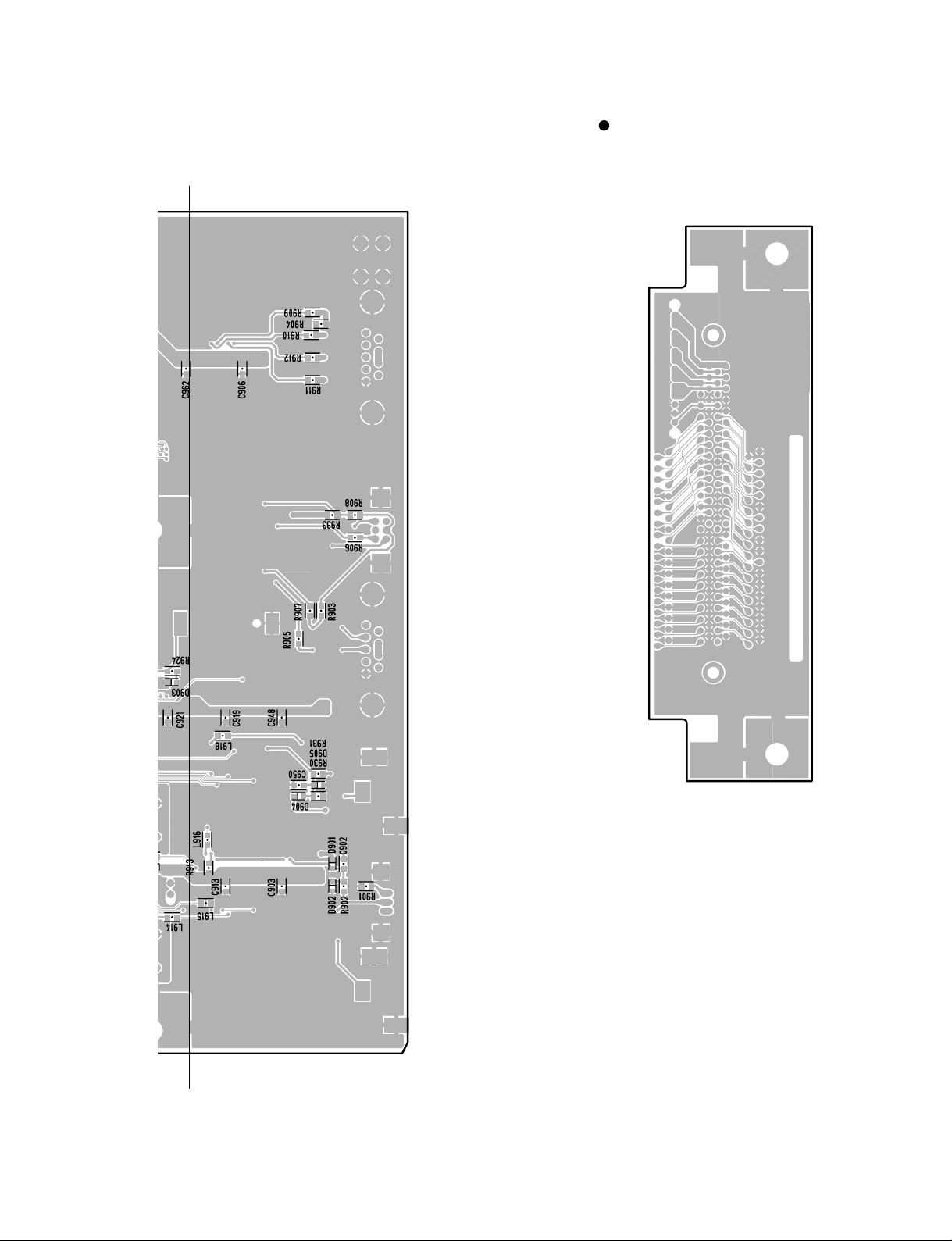
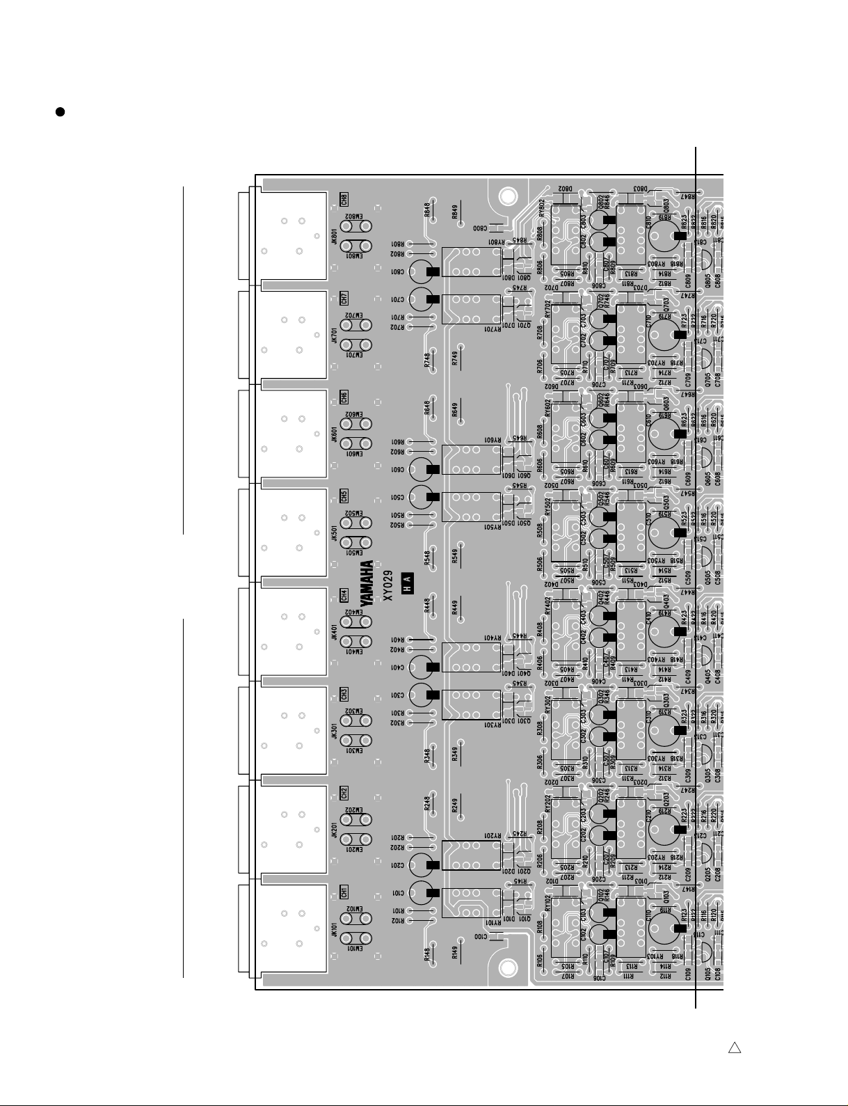
CIRCUIT BOARDS
AD824
19
AC Circuit Board (J, U, V) (XY031C0)······································································· 19
AC Circuit Board (H,W,B) (XY032C0) ······································································· 19
AD Circuit Board (XY028A0)······················································································ 28
DC Circuit Board (J, U, V) (XY031C0)······································································· 34
DC Circuit Board (H,W,B) (XY032C0) ······································································· 35
HA Circuit Board (XY029A0)······················································································ 24
JK Circuit Board (XY028A0) ······················································································ 29
MAIN Circuit Board (XY030A0)·················································································· 20
MYSL Circuit Board (XY030A0)················································································· 21
PN Circuit Board (XY027B0)······················································································ 32
SW Circuit Board (J, U, V) (XY031C0) ······································································ 19
SW Circuit Board (H,W,B) (XY032C0)······································································· 19
Note: See parts list for details of circuit board component parts.
Component side
Component side
Component side
Component side
Page 20
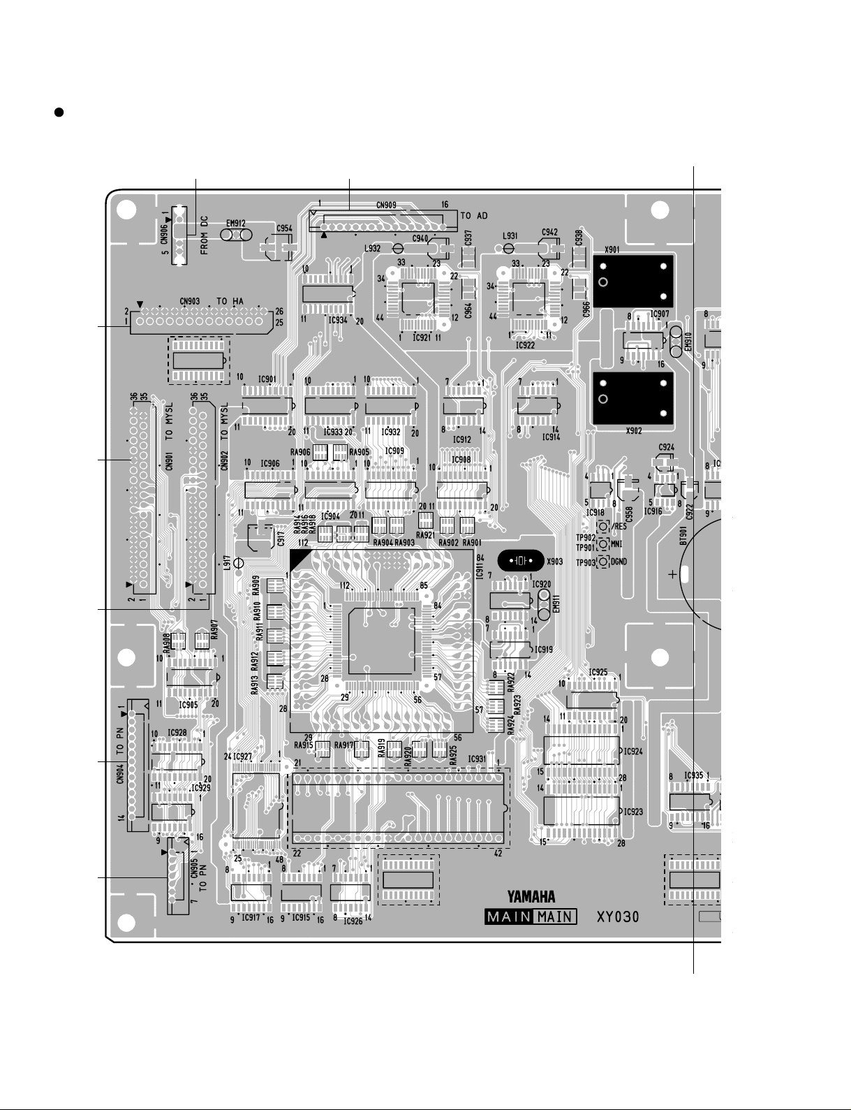
to AD-CN003
MAIN Circuit Board
A'
A
3NA-V579130
to HA-CN002to MYSL-CN054to PN-CN960to PN-CN961 to MYSL-CN053
from DC-CN010
AD824
20
Page 21
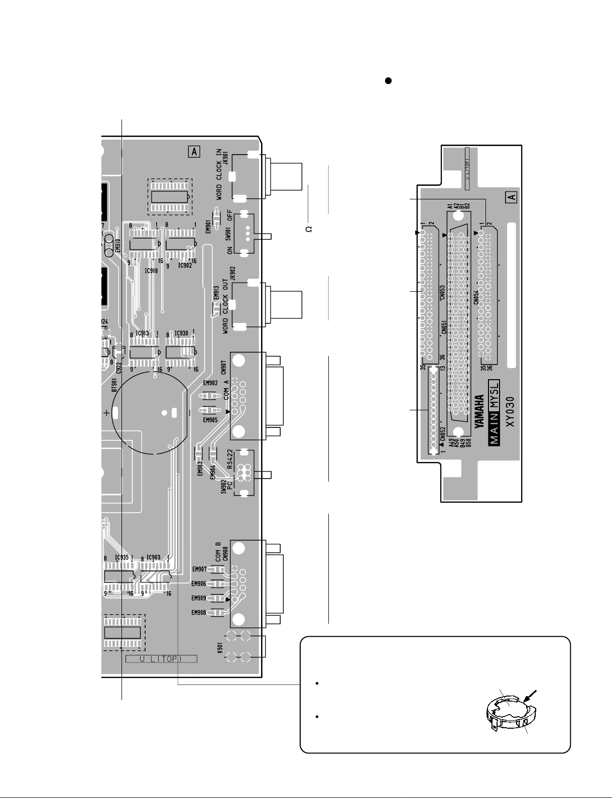
INOUT
RS422 RS422PC
WORD CLOCK
from MAIN-CN902
75
OFFON
MYSL Circuit Board
A'
A
MAIN, MYSL: 3NA-V579130
Battery VN103500
VN103600(Battery holder for VN103500)
Notice for back-up battery removal
Push the battery as shown in figure,
then the battery will pop up.
Druk de batterij naar beneden zoals
aangeven in de tekening, de batterij
springt dan naar voren.
Battery
Battery holder
COM
from DC-CN008 from MAIN-CN901
AD824
21
Component side
Component side
Page 22
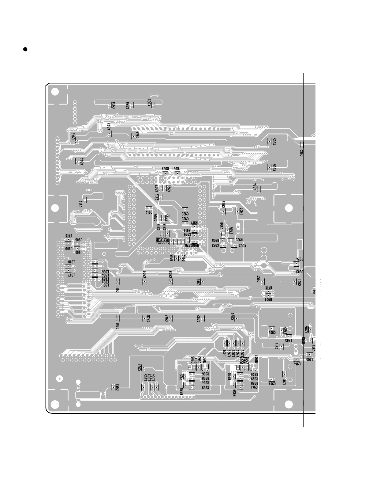
MAIN Circuit Board
B'
B
3NA-V579130
AD824
22
Page 23
E'BB'
MAIN, MYSL: 3NA-V579130
MYSL Circuit Board
AD824
23
Pattern side
Pattern side
Page 24
3NA-V579110
INPUT (BAL)
123 4 5 67 8
1
HA Circuit Board
C'
C
AD824
24
Page 25

AD824
25
3NA-V579110
to MAIN-CN903
1
C'
C
to JK-CN202to JK-CN102to DC-CN007
Component side
Page 26

HA Circuit Board
3NA-V579110
1
D'
D
AD824
26
Page 27

3NA-V579110
1
D'
D
AD824
27
Pattern side
Page 28

AD824
28
3NA-V579120
AD Circuit Board
E'
E
INSERT IN (BAL)
to MAIN-CN909
12345678
to JK-CN203
to JK-CN103
Page 29

AD824
29
JK Circuit Board
E'
E
AD, JK: 3NA-V579120
INSERT OUT (BAL)
to DC-CN011
1 2345678
from HA-CN201to AD-CN204
from HA-CN101
to AD-CN104
to PN-CN962
Component side
Component side
Page 30

AD824
30
AD Circuit Board
3NA-V579120
F'
F
Page 31

AD824
31
JK Circuit Board
F'
F
AD, JK: 3NA-V579120
Pattern side
Pattern side
Page 32

3NA-V579100
1
PN Circuit Board
G'G
G'G
from DC-CN009
to MAIN-CN905
from AD-CN002
to MAIN-CN904
AD824
32
Component side
Page 33

PN Circuit Board
3NA-V579100
1
H'H
H'H
AD824
33
Pattern side
Page 34

to MYSL-CN052
DC Circuit Board (J, U, V)
3NA-V579140
1
I'
I
I'
I
Power transformerPower transformer
to MAIN-CN906
to AD-CN001
to PN-CN963to HA-CN001
AD824
34
Component side
Page 35

DC Circuit Board (H, W, B)
3NA-V579150
1
J'
J
J'
J
to MYSL-CN052
Power transformerPower transformer
to MAIN-CN906
to AD-CN001
to PN-CN963to HA-CN001
AD824
35
Component side
Page 36

1. Preparations
1-1 Conditions
· The setting for AD824 is gain 10 dB, word clock INT 48 kHz.
· Word clock in 75 ohms is set to on.
· Signal input of only the CH to be measured.
· Input signal to NCH when measuring NCH.
· 0 dBu=0.775 Vrms
· The output impedance of the oscillator connected is 150 ohms.
· The input impedance of the oscilloscope and the level meter should be more than 100 k ohms.
· Noise measurement is corrected at 12.7 kHz, -6dB/OCT LPF.
(This is a measurement of the average value and not the actual effect value.)
· Distortion measurement is corrected at 80 kHz, -6 dB/OCT LPF.
· Use DA824 and MY8-AE card and output signal.
· The load for DA824 output 1 to 8 is 600 ohms.
· DA824 output 1 to 8 is measured at the cannon connector.
· DA824 internal gain SW is +18 dB.
1-2 Initialization
While pressing the [SEL4] key and [+48V] key, turn on the power switch. The system will start up and initialize.
2. Inspections
2-1 INPUT1 to 8CH
(1) Gain
(2) f characteristics
Conditions: Permissible range uses 1 kHz as a reference.
(3) Distortion ratio
(4) Residual noise
Conditions: Input 1 to 8 channels shorted using 150 ohms.
AD824
36
INSPECTION
Input frequency Input level GAIN Specified output level (DA824) Permissible range
1 kHz
+10 dB
+4 dB
-2 dB
-8 dB
-14 dB
-20 dB
-26 dB
-32 dB
-38 dB
-44 dB
-50 dB
-56 dB
-62 dB
+10 dB
+4 dB
-2 dB
-8 dB
-14 dB
-20 dB
-26 dB
-32 dB
-38 dB
-44 dB
-50 dB
-56 dB
-62 dB
+4 dBu +4 +/-1 dB
Input frequency Input level GAIN Permissible range
20 Hz
20 kHz
+10 dBu
-62 dBu
+10 dBu
-62 dBu
+10 dB
-62 dB
+10 dB
-62 dB
-1.5 to +1 dB
-3 to +1 dB
-1.5 to +1 dB
-3 to +1 dB
GAIN Permissible range
+10 dB Less than -90 dBu
Input frequency Input level GAIN Specified output level (DA824) Permissible range
20 Hz
20 kHz
1 kHz
+10 dBu
-62 dBu
+10 dBu
-62 dBu
+24 dBu
-48 dBu
+10 dB
-62 dB
+10 dB
-62dB
+10 dB
-62 dB
+4 dBu
+4 dBu
+4 dBu
+4 dBu
+18 dBu
+18 dBu
Less than 0.05 %
Less than 0.1 %
Less than 0.05 %
Less than 0.1 %
Less than 0.01 %
Less than 0.05 %
Page 37

(5) Noise level EIN
Conditions: CH IN 1 to 8 channels shorted using 150 ohms.
However, if it does not enter within the permissible range shown above, the measured value shall be (gain per 1 kHz) ≤ -128.
(6) Difference between channels
Specify so that it will be less than the difference in the gain range measured at (1).
(7) Cross talk between odd channels and even channels
Conditions: Input signal into odd channels.
Even channels shorted using 150 ohms.
Even channels are also the same.
(8) Phantom
Short XLR pin 2 and pin 3, connect a 10 kohms load between pins 2 and 1 and measure the voltage as shown below when the
+48V master switch is turned on.
Check that discharge starts quickly when the +48V master switch is turned off and when the [+48] key is set to off.
2-2 INSERT IN1 to 8CH
(1) Maximum input
2-3 INSERT OUT1 to 8CH
Conditions: The load for AD824 insert out 1 to 8 channels is 10 kohms.
(1) Maximum input
2-4 Operation confirmation of level meters 1 to 8
Conditions: Input specified level to AD824 input 1 to 8.
AD824 can also have simultaneous input of channels 1 to 8
Visually confirm the on and off of the peak, nominal and signal LEDs.
(1) On (Lit)
(2) Off (Not lit)
2-5 Jitter measurement
(1) INTERNAL 44.1 kHz, 48 kHz
· Insert MY8-AE card into the slot and connect to DSA1 via the D-sub-cannon converter box.
· Set AD824 word clock settings to 44.1 kHz and 48 kHz.
AD824
37
LED level Input frequency Input level Reference output level (DA824)
PEAK
NOMINAL
SIGNAL
1 kHz
1 kHz
1 kHz
+23 dBu
+12 dBu
-8 dBu
+17 dBu
+6 dBu
-14 dBu
LED level Input frequency Input level Reference output level (DA824)
PEAK
NOMINAL
SIGNAL
1 kHz
1 kHz
1 kHz
+18 dBu
+8 dBu
-12 dBu
+12 dBu
+2 dBu
-18 dBu
GAIN Permissible range
-62 dB Less than -62 dBu
WORD CLOCK Permissible range
44.1 kHz
48 kHz
Less than 5 nsec
Less than 5 nsec
Permissible range
Within 1 dB
Permissible range
DC34 to 38V
Input frequency Output level (Odd CH)
Permissible range (Even CH)
1 kHz +16 dBu
Less than -54 dBu
Input frequency Input level
Specified output level (DA824)
Permissible range
1 kHz +24 dB
+18 dBu 18 +/-1 dBu
Input frequency Input level
Specified output level (AD824)
Permissible range
1 kHz +24 dB
+24 dBu 24 +/-1 dBu
Page 38

(2) BNC
· Connect AD824 word clock out and DA824 word clock in.
· Insert MY8-AE card into the slot and connect to DSA1 via the D-sub-cannon converter box.
· Set AD824 word clock settings to BNC.
· Set AD824 word clock settings to 44.1 kHz and 48 kHz.
2-6 Fs operating range
· Connect the oscillator to AD824 word clock in.
· Set AD824 word clock settings to BNC.
(1) Fs=50.88 kHz (48 kHz+6 %)
· Set the oscillator to 50.88 kHz.
· Conduct a listening test for one minute to check that there is no noise.
(2) Fs=39.69 kHz (44.1 kHz-10 %)
· Set the oscillator to 39.69 kHz.
· Make the same input as 2-6 (1) and confirm that the same output level is attained. Or, conduct a listening test for one minute
to check that there is no noise.
3. Sound
Perform a listening test to confirm the following items.
· INPUT1 to 8
4. Initialization
While pressing the [SEL4] key and [+48V] key, turn on the power switch. The system will start up and initialize.
Others, the SW that are not controlled by the CPU are as follows.
· +48V MASTER: OFF
· WORD CLOCK IN 75 ohms: ON
· PC RS422: RS422
AD824
38
WORD CLOCK Permissible range
44.1 kHz
48 kHz
Less than 5 nsec
Less than 5 nsec
Input frequency Input level (AD824) Output level Permissible range
1 kHz +10 dBu
+4 dBu +4 +/-1 dBu
Page 39

AD824
39
1. Reparations
· Connect PC (operating MS Windows) to COM PC/RS422 terminal. The switch selects the PC.
· EUse a BNC cable to connect the IN and OUT terminals of the world clock.
· Insert the slot inspection jig (TX800810) into the slot.
· EInsert the turning jig into COM RS422 terminal (CN908). In the turning jig, DSUB 9 pins No. 2 and No3, and No.4 and No. 6
are shorted and used.
<Menu of Test Program>
The test program inspects the following eleven items.
1. SRAM CPU connection check (automatic inspection)
2. SLOT CPU connection check (automatic inspection)
3. SLOT clock relationship check (automatic inspection)
4. SLOT power supply peripheral check (automatic inspection)
5. WORD CLOCK IN/OUT connection check (automatic inspection)
6. COM RS422 terminal connection check (automatic inspection)
7. LED connection check (visual)
8. SWITCH connection check (manual inspection)
9. GAIN encoder connection check (manual inspection)
10. COM PC/RS422 terminal check (visual)
11. Initializes memory
Execute the test program after loading DA824DIAG/V1.00 program.
* The test program cannot be loaded while the turning jig is attached to COM RS422 terminal (CN908).
2. Test procedure execution program
Connect the PC and COM RS422 terminals/ CN903 with a Dsub 9-pin serial cross cable and start the terminal software (such as
Hyper Terminal).
The setting for the communication format is
Bit Rate: 38400 bps
Data length: 8 bits
Stop bit: 1
Parity: none
Next, while pressing [SEL3] and [SEL8] keys simultaneously, turn on the power. The AD824 will enter the test program mode and
“d00” will flash on the 7segLED.
The following will appear on the terminal software.
( The version of the test program will be shown as x.xx.)
TEST PROGRAM
WORD CLOCK
PC
COM
PC/RC422
AD824
SLOT INSPECTION JIG
IN
COM RS422
(CN908)
(CN907)
TURNING JIG
OUT
1234
6789
5
DSUB9P Female Connecter
(DELC-J9SAF10L9 etc.)
AD824_DIAG> AD824 Diagnosis version Vx.xx
AD824_DIAG>
Page 40

AD824
40
When in the test program execution, select the test program number for the gain encoder and the program can be executed each time
the [+48V] key is pressed.
During selection, the number will flash on the 7segLED and will change to steady on when the program is completed.
The following is the list.
[d00] Automatic inspection
[d01] LED inspection
[d02] SWITCH inspection
[d03] to [d07] is reserve.
[d08] displays the program version. (There is no need to execute during inspection.)
[d09] Initializes memory
[d10] System reset
3. [d00] Automatic inspection
Select the test program number [d00] with the gain encoder. The inspection will be automatically executed when the [+48V] key is
pressed. Or, it can also be executed by entering
<Inspection items (test)>
1. SRAM CPU connection check
2. SLOT CPU connection check
3. SLOT clock relationship connection check
4. SLOT power supply peripheral check
5. COM RS422 terminals/ CN903 connection check
6. WORD CLOCK IN/OUT terminal connection check
During the program execution, [d-] will appear on the 7segLED.
The condition will also appear on the terminal software as shown below.
If the inspection ends normally, the following will appear on the terminal software.
[d00] will also come on 7segLED.
If there is an error, the error list will appear on the terminal software
After [E003] has flashed three times on the 7segLED, [d00] will be displayed steadily.
[ERROR LIST]
[1] SRAM DATA BUS XXXX XXXX XXXX XXXX
SRAM ADDR BUS XXXX XXXX XXXX XXX
Results of SRAM (IC923, IC924) and CPU connection check
The first line on the screen shows the condition at the address bus from the left A15, A14 . . . A2, A1 (as viewed from the CPU)
The second line on the screen shows the condition at the data bus from the left D15, D14. . . . D1, D0.
[2] SLOT DATA BUS XXXX XXXX XXXX XXXX
SLOT ADDR BUS XXX XXXX XXX
SLOT CONTROL XXXX
AD824_DIAG>d00
DIAG[00] AUTO CHECK RESULT OK
AD824_DIAG>
Check SRAM DATA OOOO OOOO OOOO OOOO OK
Check SRAM ADDR OOOO OOOO OOOO OOO OK
:
:
DIAG[00] AUTOCHECK RESULT NG
ERROR LIST
[6] COM B
Page 41

AD824
41
SLOT and CPU connection check
The first line on the screen shows the condition at the data bus from the left D15, D14. . . . D1, D0.
The second line on the screen shows the condition at the address bus from the left A15, A14 . . . A2, A1.
The third line on the screen shown the condition at other control lines from the left /CON-MY,/IRQ-MY, RX-MY, TX-MY.
For each item, an “0” is used to indicate normal and “X” is used to indicate an abnormality.
[3] SLOT CLOCK XXX XXXX
Connection check of slot clock line
The condition is shown from the left as 256FS-MY, 128FS-MY, 64FS-MY, SYNC-MY, FS-MY, WCLK-MY.
For each item, an “0” is used to indicate normal and “X” is used to indicate an abnormality.
[4] SLOT +20D
SLOT +5D
SLOT -5A
SLOT +5A
SLOT -15A
SLOT +15A
Slot power supply peripheral connection check
Only the NG systems from the test results will be shown on the screen.
[5] WC BNC
Displayed on the screen when the results of the word clock IN terminal/ JK901 and CPU connection are NG.
[6] COM B
Displayed on the screen when the results of the COM RS422 terminals/ CN903 and CPU connection are NG.
4. [d01] LED inspection
Select the test program number [d01] with the gain encoder. The LED inspection will be executed when the [+48V] key is pressed.
Or, it can also be executed by entering
When this program number is executed, the following sequence will occur. Check them visually.
1. The LEDs in the drawing below will come on one at a time.
2. The 7segLED will come on one column at time “0,1,2,3,4,5,6,7,8,8.”
3. All LEDs, except the level LEDs, will flash 3 times.
4. [d01] on the 7segLED will come on.
In addition, the following will be displayed on the terminal software.
AD824_DIAG>d01
+48V MASTER
PEAK
NOMINAL
SIGNAL
+48V
PEAK
NOMINAL
SIGNAL
+48V
GAIN
dB
44.1kHz 48kHz BNC
SLOT
INTERNAL
WORD CLOCK
SEL
12345678
SEL
OFF ON
POWER
DIAG[01]LED CHECK...............................................
............DONE
AD824_DIAG>
Page 42

AD824
42
5. [d02] SWITCH inspection
Select the test program number [d02] with the gain encoder. The LED inspection will be executed when the [+48V] key is pressed.
Or, it can also be executed by entering
1. The LED near the relevant switch flashes.
2. When the switch is pressed, the LED changes to steady on.
* The +48V MASTER is inspected by changing the switch.
3. The LED for the next switch to be inspected flashes.
4. Steps 1 to 3 are repeated. If there is a problem with the connection, the time over functions and [E02] will flash three
times on 7segLED and ends when [d02] is steady on.
If normal, it ends when [d02] is steady on.
If there is an error, the terminal software will display the switches that had errors.
6. [d08] Program version display.
Select the test program number [d08] with the gain encoder. When the [+48V] key is pressed, the program version will be displayed
on 7segLED for approximately one second.
7. [d09] Initializes memory
Select the test program number [d09] with the gain encoder. When the [+48V] key is pressed, memory initialization is executed. Or,
it can also be executed by entering
When this program number is executed, the following will be displayed on the terminal software.
8. [d10] System reset
Select the test program number [d10] with the gain encoder. When the [+48V] key is pressed, the system is reset and it is possible
to return to the normal operating mode.
Or, it can also be executed by entering
AD824_DIAG>d02
AD824_DIAG>d09
+48V MASTER
PEAK
NOMINAL
SIGNAL
+48V
PEAK
NOMINAL
SIGNAL
+48V
GAIN
dB
44.1kHz 48kHz BNC
SLOT
INTERNAL
WORD CLOCK
SEL
12345678
SEL
OFF ON
DIAG[02] SWITCH CHECK NG or TIME OVER
WORD CLOCK (SW961)
SEL 1 (SW962)
:
:
SEL 8 (SW969)
+48V (SW970)
+48V MASTER (SW960)
AD824_DIAG>
DIAG[09] MEMORY INITIALIZE DONE
AD824_DIAG>
AD824_DIAG>reset
Page 43

AD824
43
FLASH ROM UPGRADE
The AD824 is equipped with flash memory (MAIN: IC927).
The software in the flash memory can be upgraded from the
COM PC/RS422 terminal. Upgrades can also be performed
from a Windows PC using the dedicated software.
When the power is turned on, a check is made to confirm
that the system program is in the flash memory. If the
proper system is present, it is executed. If the program is
not present, or if there is an error, the program boot mode is
entered automatically.
* Warning*
The program cannot be loaded while the turning
jig is attached to COM RS422 terminal (CN908) and
the inspection jig is attached to the slot.
Check that has been removed befor performing the
upgrade.
1. Connection
Connect the PC and AD824 COM PC/RS422 terminals by
Dsub 9 pin serial cross cables.
A changeover switch of PC/RS422 selects PC.
In addition, if connection is made in the following manner,
upgrades can also be made to AD824 after the second unit.
Note that a condition for this is that the device number has
been set beforehand. (The software shown below is
compatible up to the fourth unit.)
2. Software
LoadAD824/V1.0 is used as the software. When the folder is
open, three files are displayed on the screen: LoadAD824.exe,
TimeStamp.exe and 02rv2.dll. The two files requiring an
upgrade are LoadAD824.exe and 02rv2.dll.
2-1. Start the software
Click on LoadAD824.exe. The program will start and the
following screen will be displayed.
It is also possible to switch the PC COM terminal that is
connected by the dialogue box in the upper right. (The figure
shows that COM1 is selected.)
In addition, when loading the program to AD824 after the
second unit, switching of the device number is done by the
dialogue box at the upper center. (The figure shows that DEV
1 is selected.)
2-2. Connection with AD824
Click the [Connect] switch and the AD824 program is loaded.
The commands are sent and if the connection is successful,
the following message will appear.
Click OK and the AD824 will display the device number and
part of the version of the current program in the 7segLED.
For example, if the device number is 1 and the program
version is 1.00, “d01” and “r1.0” will light up alternately.
2-3. Reading the files to be loaded
Click the [Browse] switch and the following window will
open. Designate the files to be loaded to the AD824 and click
the [Open] switch.
PC
AD824
COM
PC/RS422
PC
AD824
COM
PC/RS422
COM
RS422
AD824
COM
PC/RS422
COM
RS422
Page 44

AD824
44
2-4. Loading the program
Click the [Load] switch and the program will start to load.
When completed, the following message will be displayed.
2-5. Others
Click the [Disconnect] switch to reset the AD824 to the
regular mode.
Page 45

AD824
45
ERROR MESSAGES
The AD824 performs several diagnostic checks when it’s turned on. If a problem isdetected, one of the following
error codes appears briefly on the GAIN display.
Internal backup-battery voltage low.
Internal memory data corrupt.
Internal backup-battery voltage low and internal memory data corrupt.
Page 46

CONTENTS
OVERALL ASSEMBLY······························································································································ 2
FRONT PANEL ASSEMBLY····················································································································· 4
REAR PANEL ASSEMBLY ······················································································································· 5
DC ASSEMBLY········································································································································· 6
ELECTRICAL PARTS ·························································································································7~31
PARTS LIST
WARNING
Components having special characteristics are marked and must be replaced with parts having
specification equal to those originally installed.
A: Australian model
B: British model
C: Canadian model
D: German model
E: European model
F: French model
H: North European model
I : Indonesian model
J: Japanese model
M: South African model
O: Chinese model
Q: South-east Asia model
T: Taiwan model
U: U.S.A. model
V: General export model (110 V)
W: General export model (220 V)
N,X:General export model
Y: Export model
Notes: DESTINATION ABBREVIATIONS
• The numbers in “ QTY ” show quantities for each unit.
• The parts with “ - - ” in “ PART NO. ” are not available as spare parts.
• The mark “ ” in the remarks column indicates that these parts are interchangeable.
• The second letter of the shaded ( ) part number is O, not zero.
• The second letter of the shaded ( ) part number is I, not one.
AD CONVERTER
Page 47

AD824
2
OVERALL ASSEMBLY
500
440
460
470
90
100
140
130
120
420
445
400
100
450
390
330
530
520
290
80
40
Rear panel assembly: see page 5
150
270
540
310
320
300
50
380
350
340
360
200
210
205
160
170
30
60
250
240
370
430
480
490
230
25
35
70
80
33
34
32
140
130
120
190
120
180
110
10b
10c
10d
10a
10
220
260
DC assembly: see page 6
Front panel assembly: see page 4
Page 48

AD824
3
OVERALL ASSEMBLY
Overall Assembly
Overall Assembly
Overall Assembly
Overall Assembly
Bottom Assembly
Bottom Chassis
Leg Black
Bind Head Tapping Screw-B
Protection Sheet
Label
Label
Holder
Ferrite Core
Cord Holder
Holder, Cord
Rear Panel Assembly
Rear Panel Assembly
Rear Panel Assembly
Rear Panel Assembly
Bind Head Tapping Screw-B
Bind Head Screw
Side Panel
Bind Head Tapping Screw-B
Side Panel
Bind Head Tapping Screw-B
Front Panel Assembly
Front Panel Assembly
Bind Head Tapping Screw-B
Rack Mount Angle
Oval Head Screw
Connector Assembly
PCB Support
Bonding Tapping Screw-B
Power Transformer
Power Transformer
Power Transformer
Bind Head Tapping Screw-B
DC Assembly
DC Assembly
Cord Binder
Bind Head Tapping Screw-B
Support, OPT
Circuit Board
Connector Assembly
Bind Head Screw
Bonding Tapping Screw-B
Circuit Board
Bonding Screw
Bonding Screw
Bind Head Tapping Screw-B
Circuit Board
Bonding Tapping Screw-B
PCB Holder
Bonding Tapping Screw-B
PCB Holder
Bonding Tapping Screw-B
Circuit Board
Bonding Tapping Screw-B
Bind Head Tapping Screw-B
Shield Sheet
Bind Head Tapping Screw-B
Circuit Board
Ground Film, AD
Bonding Tapping Screw-B
Bind Head Tapping Screw-B
Connector Assembly
Lithium Battery
Top Cover
Bind Head Tapping Screw-B
DESCRIPTION
10
10a
10b
10c
10d
25
30
32
33
34
35
40
40
40
40
50
60
70
80
90
100
110
110
120
130
140
150
160
170
180
180
180
190
200
200
205
210
220
230
240
250
260
270
290
300
310
320
330
340
350
360
370
380
390
400
420
430
440
445
450
460
470
480
490
500
REF NO.
- -
- -
- -
- -
- V4067500
CB806590
VR138400
- -
- -
- CB835590
VC362700
CB069250
CB095100
- -
- -
- -
- VC688800
EG340360
V4068400
VC688800
V4605100
VC688800
- -
- VC688800
V4705100
V6221000
- -
- VN413300
XY173A00
XY174A00
XY175B00
VC688800
V5610800
V5610900
CB817510
VC688800
V4093800
V5792200
- EG340360
VN413300
V5792100
VS154500
VS863000
EP600230
V5791900
VN413300
V5274100
VN413300
- VN413300
V5792000
VN413300
EP600230
V5725100
EP600230
V5791100
- VN413300
EP600230
MF126200
VN103500
V5202400
VC688800
PART NO.
BL
4.0X12 MFZN2BL
BK-1
K-103G
A4.0X8 MFZN2BL
4.0X8 MFZN2BL
RIGHT
A4.0X8 MFZN2BL
LEFT
A4.0X8 MFZN2BL
A4.0X8 MFZN2BL
B4.0X10 MFZN2BL
AC-SW
MAIN
3.0X8 MFZN2BL
J A
UL,CSA A
CEE A
A4.0X8 MFZN2BL
S-14B
A4.0X8 MFZN2BL
MYSL
36P 140mm P=1.25
4.0X8 MFZN2BL
3.0X8 MFZN2BL
MAIN
4.0X8 MFZN2BL
3.0X6 MFZN2BL
3.0X6 MFZN2BL
AD
3.0X8 MFZN2BL
RIGHT
3.0X8 MFZN2BL
LEFT
3.0X8 MFZN2BL
JK
3.0X8 MFZN2BL
3.0X6 MFZN2BL
AD
3.0X6 MFZN2BL
HA
3.0X8 MFZN2BL
3.0X6 MFZN2BL
26P 200mm P=1.25
CR2032
A4.0X8 MFZN2BL
AD824
J (V560980)
U,V (V560990)
H,W (V561000)
B (V561010)
(V580690)
(V553110)
U,V (VA03930)
H,W,B (V567270)
H,W,B
H,W,B
H,W,B
J (V561020)
U,V (V561030)
H,W (V561040)
B (V561050)
U,V,H,W,B
J,U,V (V561060)
H,W,B (V561070)
(V545950)
(V527400)
J
U,V
H,W,B
J,U,V
H,W,B
(MF13614)
(V527420)
(V647450)
REMARKS
4
4
4
4
4
6
2
6
2
4
2
2
2
4
2
5
6
2
2
6
2
2
16
4
14
QTY
RANK
*
*
*
*
*
*
*
*
*
*
*
*
*
10
03
01
03
01
04
01
01
01
01
10
01
10
01
01
08
01
12
12
12
01
03
01
05
01
01
01
01
01
01
01
01
01
01
01
01
01
04
03
11
01
*
:
New Parts RANK: Japan only
Page 49

AD824
4
IF Plate
Bind Head Screw
Label
ACCESSORIES
DSUB Cable
DESCRIPTION
520
530
540
REF NO.
VZ678500
VP156900
CB076120
V5436200
PART NO.
A4.0X12 MFZN2BL
9P
H,W,B
REMARKS
2
QTY
RANK
05
01
07
*
:
New Parts RANK: Japan only
FRONT PANEL ASSEMBLY
10
40
50
20
30
90
60
70
100
110
80
FRONT PANEL ASSEMBLY
Front Panel Assembly
Front Panel Assembly
Sub Chassis
Circuit Board
Bind Head Tapping Screw-B
Circuit Board
Circuit Board
Bonding Screw
Front Panel
Cover
Oval Head Screw
Power Switch Knob
Escutcheon, Power Switch
Knob
DESCRIPTION
10
20
30
40
40
50
60
70
80
90
100
110
REF NO.
- -
- V4067800
V5791000
EP600230
V5792500
V5792800
VS863000
V4067900
V4068900
VS153600
VL812900
VL813000
VM840900
PART NO.
PN
3.0X6 MFZN2BL
SW
SW
3.0X6 MFZN2BL
4.0X8 MFZN2BL
AD824
J,U,V (V561060)
H,W,B (V561070)
J,U,V
H,W,B
POWER ON/OFF
GAIN
REMARKS
4
2
6
QTY
RANK
*
*
*
*
*
07
01
01
04
01
03
03
03
*
:
New Parts RANK: Japan only
Page 50

AD824
5
REAR PANEL ASSEMBLY
Rear Panel Assembly
Rear Panel Assembly
Rear Panel Assembly
Rear Panel Assembly
Rear Panel
Rear Panel
Rear Panel
AC Cord Assembly
AC Cord Assembly
AC Cord Assembly
AC Cord Assembly
Cord Strain Relief
Cord Strain Relief
Cord Strain Relief
Circuit Board
Circuit Board
Bind Head Tapping Screw-B
Ferrite Core
Cord Holder
AC Shield Cover
Bonding Tapping Screw-B
Fuse
Fuse
DESCRIPTION
10
10
10
20
20
20
20
30
30
30
40
40
60
80
90
100
110
F001
F001
REF NO.
- -
- -
- -
- V4068100
V5254600
V5254700
VS228900
VS229000
VS229100
VS229200
CB806850
CB811230
CB032840
V5792300
V5792600
VC688800
VC362700
CB069250
V5274400
VN413300
KB003570
KB003040
PART NO.
AD
AD
AD
2P 15A
3P 10A
3P 6A
3P 10A
SR-6N3-4
SR-6N-4
SR-5N-4
AC
AC
A4.0X8 MFZN2BL
FR25/15/12-1400L
BK-1
3.0X8 MFZN2BL
2.00A JU
1.00A S
AD824
J (V561020)
U,V (V561030)
H,W (V561040)
B (V561050)
J
U,V
H,W,B
J
U,V
H,W
B
J
U,V
H,W,B
J,U,V
H,W,B
J,U,V
H,W,B
REMARKS
3
2
QTY
RANK
*
*
*
*
*
07
07
07
09
10
10
11
02
02
03
01
04
01
03
01
01
01
REAR PANEL ASSEMBLY
*
:
New Parts RANK: Japan only
110
100
F001
40
80
90
60
10
30
20
Page 51

AD824
6
DC ASSEMBLY
DC Assembly
DC Assembly
Heat Sink
Insulation Sheet
Circuit Board
Circuit Board
Bonding Tapping Screw-B
Holder, Transistor
Pan Head Screw
Fuse
Fuse
Fuse
Fuse
Fuse
Fuse
Fuse
Fuse
Fuse
Fuse
Fuse
Fuse
DESCRIPTION
10
20
30
30
40
50
60
F002
F002
F003
F003
F004
F004
F005
F005
F006
F006
F007
F007
REF NO.
V5610800
V5610900
- V4068800
V5792400
V5792700
VN413300
- EL200020
KB003560
KB003060
KB003560
KB003060
KB003570
KB003070
KB003570
KB003070
KB003630
KB003240
KB003470
KB003010
PART NO.
DC
DC
3.0X8 MFZN2BL
SP 4.0X8 MFZN2Y
1.60A JU
1.60A S
1.60A JU
1.60A S
2.00A JU
2.00A S
2.00A JU
2.00A S
5.00A JU
5.00A S
500mA 250V JU
500mA S
AD824
J,U,V
H,W,B
(V406870)
J,U,V
H,W,B
(V406820)
J,U,V
H,W,B
J,U,V
H,W,B
J,U,V
H,W,B
J,U,V
H,W,B
J,U,V
H,W,B
J,U,V
H,W,B
REMARKS
3
4
QTY
RANK
*
*
*
*
03
01
01
01
01
01
01
01
01
01
01
01
01
01
01
DC ASSEMBLY
*
:
New Parts RANK: Japan only
40
50
F006
F003
F002
F005
F004
F007
30
20
10
60
Page 52

AD824
7
ELECTRICAL PARTS
Circuit Board
Circuit Board
Circuit Board
Circuit Board
Circuit Board
Circuit Board
Circuit Board
Circuit Board
Circuit Board
Circuit Board
Circuit Board
Circuit Board
Circuit Board
Circuit Board
Circuit Board
Circuit Board
Circuit Board
Circuit Board
Cap Screw-B
AC Shield Plate
Heat Sink
Insulation Sheet
Jumper Wire
Capacitor
Capacitor
Ceramic Capacitor-E
Ceramic Capacitor-E
Electrolytic Cap.
Electrolytic Cap.
Electrolytic Cap.
Electrolytic Cap.
Electrolytic Cap.
Electrolytic Cap.
Mylar Capacitor
Mylar Capacitor
Ceramic Capacitor-E
Electrolytic Cap.
Electrolytic Cap.
Electrolytic Cap.
Ceramic Capacitor-E
Electrolytic Cap.
Base Post Connector
Base Post Connector
Base Post Connector
Base Post Connector
Base Post Connector
Base Post Connector
Wire Trap
Wire Trap
Wire Trap
Wire Trap
Wire Trap
Diode
Diode
Diode Stack
Diode Stack
Diode Stack
Diode Stack
LC Filter
LC Filter
Fuse Holder
Fuse Holder
IC
IC
IC
IC
IC
IC
DESCRIPTION
C001
C002
C003
-018
C020
C021
C022
C023
C024
C026
C028
-033
C034
C035
C037
-042
C043
C044
CN001
CN002
CN003
CN004
CN005
CN006
CN007
CN008
CN009
CN010
CN011
D006
-018
DB001
DB002
DB003
DB004
EM001
-018
FZ001
-007
IC001
IC002
IC003
IC004
IC005
IC006
REF NO.
V5792300
V5792600
V5792400
V5792700
V5792500
V5792800
V5791900
V5792000
V5791100
V5792100
V5792200
V5791000
V5792300
V5792600
V5792400
V5792700
V5792500
V5792800
V5848200
V5273900
V5731700
V5724900
VA078900
V3311600
V5170300
VS589000
VS589000
UR659220
UR659220
UR639470
UR639470
VT947800
VT598700
UA355100
UA355100
VS589000
UR897100
UR858100
UR838100
VS589000
UR897470
LB932030
LB933030
LB933030
LB933040
LB932060
LB932050
VK025800
VK025700
VF728200
VK024900
VK025700
VB481900
VB481900
VT359600
VT359600
VN011300
VB845300
FZ006970
FZ006970
VP206500
VP206500
XD853A00
XD854A00
XR607A00
XK309A00
XR607A00
XH672A00
PART NO.
AC
AC
DC
DC
SW
SW
AD
JK
HA
MAIN
MYSL
PN
AC
AC
DC
DC
SW
SW
3.0X10 MFZN2BL
DB
DB
0.55
0.010 250V J.U.C.S
0.220 275V U.C.S
4700P 500V M
4700P 500V M
2200 35.0V
2200 35.0V
4700 16.0V
4700 16.0V
10000 16 USP
1000 100 USP
0.1000 50V J
0.1000 50V J
4700P 500V M
10.0 100.0V
100.00 35.0V
100.00 16.0V
4700P 500V M
47.0 100.0V
VH 3P TE
VH 3P SE
VH 3P SE
VH 4P SE
VH 6P TE
VH 5P TE
52147 14P TE
52147 13P TE
52147 10P TE
52147 5P TE
52147 13P TE
11ES4
11ES4
D3SBA20 4.0A 200V
D3SBA20 4.0A 200V
D3SBA20 4.0A 200V
S1WB(A)60 1.0A 60
LS MT Y223NB
LS MT Y223NB
EYF-52BC
EYF-52BC
NJM7815FA
NJM7915FA
UPC2405AHF
NJM7905FA
UPC2405AHF
PQ05RF2
AD824
J,U,V (XY031C0)
H,W,B (XY032C0)
J,U,V (XY031C0)
H,W,B (XY032C0)
J,U,V (XY031C0)
H,W,B (XY032C0)
(XY028A0)
(XY028A0)
(XY029A0)
(XY030A0)
(XY030A0)
(XY027B0)
J,U,V (XY031C0)
H,W,B (XY032C0)
J,U,V (XY031C0)
H,W,B (XY032C0)
J,U,V (XY031C0)
H,W,B (XY032C0)
REGULATOR +15V
REGULATOR -15V
REGULATOR +5V
REGULATOR -5V
REGULATOR +5V
REGULATOR +5V 2A
REMARKS
2
QTY
RANK
*
*
*
*
*
*
*
*
*
*
*
*
*
*
*
*
*
*
*
*
*
01
03
01
01
01
01
01
02
02
02
02
04
05
01
01
01
01
01
01
01
01
01
01
01
01
01
01
01
01
01
01
01
01
01
03
03
03
02
02
02
01
01
03
03
04
03
04
04
ELECTRICAL PARTS
*
:
New Parts RANK: Japan only
Page 53

AD824
8
IC
Jumper Wire
Jumper Wire
Land Terminal
Land Terminal
Line Filter
Metal Oxide Film Resistor
Carbon Resistor
Carbon Resistor
Carbon Resistor
Metal Oxide Film Resistor
Carbon Resistor
Carbon Resistor
Carbon Resistor
Metal Oxide Film Resistor
Carbon Resistor
Carbon Resistor
Carbon Resistor
Metal Film Resistor
Metal Film Resistor
Carbon Resistor
Push Switch
Transistor
Transistor
Transistor
Transistor
Transistor
Transistor
Zener Diode
Zener Diode
Zener Diode
Circuit Board
Circuit Board
Jack Holder
Electrolytic Cap. (chip)
Electrolytic Cap. (chip)
Electrolytic Cap. (chip)
Electrolytic Cap. (chip)
Monolithic Ceramic Cap.
Monolithic Ceramic Cap.
Electrolytic Cap.
Electrolytic Cap.
Monolithic Ceramic Cap.
Monolithic Ceramic Cap.
Monolithic Ceramic Cap.
Monolithic Ceramic Cap.
Monolithic Ceramic Cap.
Monolithic Ceramic Cap.
Electrolytic Cap.
Electrolytic Cap.
Electrolytic Cap.
Electrolytic Cap.
Monolithic Ceramic Cap.
Monolithic Ceramic Cap.
Electrolytic Cap.
Monolithic Ceramic Cap.
Monolithic Ceramic Cap.
Mylar Capacitor
Monolithic Ceramic Cap.
Electrolytic Cap.
Monolithic Ceramic Cap.
Monolithic Ceramic Cap.
Electrolytic Cap.
Monolithic Ceramic Cap.
Monolithic Ceramic Cap.
Electrolytic Cap.
Monolithic Ceramic Cap.
Electrolytic Cap.
Electrolytic Cap.
DESCRIPTION
IC007
J001
J004
K001
-003
L001
R004
R005
R008
R009
R010
R012
-018
R019
R020
R021
R022
R023
R024
R025
R027
SW001
TR001
TR002
TR004
TR006
TR007
TR008
ZD001
ZD002
ZD003
C001
C002
C003
C004
C005
-008
C011
C012
C013
C015
C101
C102
C103
C104
C105
C106
C116
C117
C118
-120
C121
C122
C123
C127
C130
C131
C132
C133
C134
C135
C136
C137
C138
C139
C140
REF NO.
XD631A00
VA078900
VA078900
BB069510
BB069510
VQ764500
VC749400
HF757220
HF756560
HF758100
VC743400
HF757100
HF757100
HF756220
VC750200
HF756220
HF757100
HF757100
VC330400
VC328600
HF756470
V3127000
VS150800
VM923000
VS150800
VS150800
VM923000
IA101590
VQ554100
VQ558500
VQ557800
V5791900
V5792000
V5274300
V5829300
V5829300
V5829200
V5829200
UB245100
UB245100
UU148100
UU148100
UB245100
UB245100
UB044100
UB044100
UB051220
UB051220
UU148100
UU148100
UU167100
UU167100
UB052100
UB052100
UU167100
UB052220
UB052220
UA353220
UB245100
UU167100
UB245220
UB245100
UU167100
UB245220
UB245100
UU167100
UB245100
UU147220
UU147220
PART NO.
PST518B-TP
0.55
0.55
#6951 A-8
#6951 A-8
PLAC1522R0R01B1
5.6K 1W J
22.0K 1/4 J
5.6K 1/4 J
100.0K 1/4 J
22.0 1W J
10.0K 1/4 J
10.0K 1/4 J
2.2K 1/4 J
12.0K 1W J
2.2K 1/4 J
10.0K 1/4 J
10.0K 1/4 J
47.0K 1/4 F
8.2K 1/4 F
4.7K 1/4 J
ESB92S23B J.U.C.S
2SC3200 GR
2SD2015 *
2SC3200 GR
2SC3200 GR
2SD2015 *
2SA1015 O,Y
MTZJ7.5A 7.5V
MTZJ33B 33.0V
MTZJ27B 27.0V
AD
JK
100 16V 16SG100M+T
100 16V 16SG100M+T
100 20V 20SG100M+T
100 20V 20SG100M+T
F 0.100 25V Z
F 0.100 25V Z
100.00 25.0V
100.00 25.0V
F 0.100 25V Z
F 0.100 25V Z
F 0.010 50V Z
F 0.010 50V Z
SL 22P 50V J
SL 22P 50V J
100.00 25.0V
100.00 25.0V
10.00 50.0V
10.00 50.0V
SL 100P 50V J
SL 100P 50V J
10.00 50.0V
SL 220P 50V J
SL 220P 50V J
2200P 50V J
F 0.100 25V Z
10.00 50.0V
F 0.220 25V Z
F 0.100 25V Z
10.00 50.0V
F 0.220 25V Z
F 0.100 25V Z
10.00 50.0V
F 0.100 25V Z
22.00 25.0V
22.00 25.0V
SYSTEM RESET
POWER ON/OFF
(XY028A0)
(XY028A0)
REMARKS
4
QTY
RANK
*
*
*
*
*
*
*
*
*
*
02
01
01
03
01
01
01
01
01
01
01
01
01
01
01
01
01
01
01
02
01
03
01
01
03
01
01
01
01
01
04
04
04
04
01
01
01
01
01
01
01
01
01
01
01
01
01
01
01
01
01
01
01
01
01
01
01
01
01
01
01
*
:
New Parts RANK: Japan only
Page 54

AD824
9
Monolithic Ceramic Cap.
Monolithic Ceramic Cap.
Monolithic Ceramic Cap.
Monolithic Ceramic Cap.
Monolithic Ceramic Cap.
Monolithic Ceramic Cap.
Electrolytic Cap.
Electrolytic Cap.
Electrolytic Cap.
Electrolytic Cap.
Monolithic Ceramic Cap.
Monolithic Ceramic Cap.
Electrolytic Cap.
Monolithic Ceramic Cap.
Monolithic Ceramic Cap.
Mylar Capacitor
Monolithic Ceramic Cap.
Monolithic Ceramic Cap.
Monolithic Ceramic Cap.
Monolithic Ceramic Cap.
Monolithic Ceramic Cap.
Monolithic Ceramic Cap.
Electrolytic Cap.
Electrolytic Cap.
Electrolytic Cap.
Electrolytic Cap.
Monolithic Ceramic Cap.
Monolithic Ceramic Cap.
Electrolytic Cap.
Monolithic Ceramic Cap.
Monolithic Ceramic Cap.
Mylar Capacitor
Monolithic Ceramic Cap.
Electrolytic Cap.
Monolithic Ceramic Cap.
Monolithic Ceramic Cap.
Electrolytic Cap.
Monolithic Ceramic Cap.
Monolithic Ceramic Cap.
Electrolytic Cap.
Monolithic Ceramic Cap.
Electrolytic Cap.
Electrolytic Cap.
Monolithic Ceramic Cap.
Monolithic Ceramic Cap.
Monolithic Ceramic Cap.
Monolithic Ceramic Cap.
Monolithic Ceramic Cap.
Monolithic Ceramic Cap.
Electrolytic Cap.
Electrolytic Cap.
Electrolytic Cap.
Electrolytic Cap.
Monolithic Ceramic Cap.
Monolithic Ceramic Cap.
Electrolytic Cap.
Monolithic Ceramic Cap.
Monolithic Ceramic Cap.
Mylar Capacitor
Monolithic Ceramic Cap.
Monolithic Ceramic Cap.
Monolithic Ceramic Cap.
Monolithic Ceramic Cap.
Monolithic Ceramic Cap.
Monolithic Ceramic Cap.
Electrolytic Cap.
Electrolytic Cap.
Electrolytic Cap.
Electrolytic Cap.
Monolithic Ceramic Cap.
DESCRIPTION
C143
-146
C201
C202
C203
C204
C205
C206
C216
C217
C218
-220
C221
C222
C223
C227
C243
-246
C301
C302
C303
C304
C305
C306
C316
C317
C318
-320
C321
C322
C323
C327
C330
C331
C332
C333
C334
C335
C336
C337
C338
C339
C340
C343
-346
C401
C402
C403
C404
C405
C406
C416
C417
C418
-420
C421
C422
C423
C427
C443
-446
C501
C502
C503
C504
C505
C506
C516
C517
C518
REF NO.
UB044100
UB044100
UB044100
UB044100
UB051220
UB051220
UU148100
UU148100
UU167100
UU167100
UB052100
UB052100
UU167100
UB052220
UB052220
UA353220
UB044100
UB044100
UB044100
UB044100
UB051220
UB051220
UU148100
UU148100
UU167100
UU167100
UB052100
UB052100
UU167100
UB052220
UB052220
UA353220
UB245100
UU167100
UB245220
UB245100
UU167100
UB245220
UB245100
UU167100
UB245100
UU147220
UU147220
UB044100
UB044100
UB044100
UB044100
UB051220
UB051220
UU148100
UU148100
UU167100
UU167100
UB052100
UB052100
UU167100
UB052220
UB052220
UA353220
UB044100
UB044100
UB044100
UB044100
UB051220
UB051220
UU148100
UU148100
UU167100
UU167100
UB052100
PART NO.
F 0.010 50V Z
F 0.010 50V Z
F 0.010 50V Z
F 0.010 50V Z
SL 22P 50V J
SL 22P 50V J
100.00 25.0V
100.00 25.0V
10.00 50.0V
10.00 50.0V
SL 100P 50V J
SL 100P 50V J
10.00 50.0V
SL 220P 50V J
SL 220P 50V J
2200P 50V J
F 0.010 50V Z
F 0.010 50V Z
F 0.010 50V Z
F 0.010 50V Z
SL 22P 50V J
SL 22P 50V J
100.00 25.0V
100.00 25.0V
10.00 50.0V
10.00 50.0V
SL 100P 50V J
SL 100P 50V J
10.00 50.0V
SL 220P 50V J
SL 220P 50V J
2200P 50V J
F 0.100 25V Z
10.00 50.0V
F 0.220 25V Z
F 0.100 25V Z
10.00 50.0V
F 0.220 25V Z
F 0.100 25V Z
10.00 50.0V
F 0.100 25V Z
22.00 25.0V
22.00 25.0V
F 0.010 50V Z
F 0.010 50V Z
F 0.010 50V Z
F 0.010 50V Z
SL 22P 50V J
SL 22P 50V J
100.00 25.0V
100.00 25.0V
10.00 50.0V
10.00 50.0V
SL 100P 50V J
SL 100P 50V J
10.00 50.0V
SL 220P 50V J
SL 220P 50V J
2200P 50V J
F 0.010 50V Z
F 0.010 50V Z
F 0.010 50V Z
F 0.010 50V Z
SL 22P 50V J
SL 22P 50V J
100.00 25.0V
100.00 25.0V
10.00 50.0V
10.00 50.0V
SL 100P 50V J
REMARKS
QTY
RANK
*
*
*
*
*
*
*
*
01
01
01
01
01
01
01
01
01
01
01
01
01
01
01
01
01
01
01
01
01
01
01
01
01
01
01
01
01
01
01
01
01
01
01
01
01
01
01
01
01
01
01
01
01
01
01
01
01
01
01
01
01
01
01
01
01
01
01
01
01
01
*
:
New Parts RANK: Japan only
Page 55

AD824
10
Monolithic Ceramic Cap.
Electrolytic Cap.
Monolithic Ceramic Cap.
Monolithic Ceramic Cap.
Mylar Capacitor
Monolithic Ceramic Cap.
Electrolytic Cap.
Monolithic Ceramic Cap.
Monolithic Ceramic Cap.
Electrolytic Cap.
Monolithic Ceramic Cap.
Monolithic Ceramic Cap.
Electrolytic Cap.
Monolithic Ceramic Cap.
Electrolytic Cap.
Electrolytic Cap.
Monolithic Ceramic Cap.
Monolithic Ceramic Cap.
Monolithic Ceramic Cap.
Monolithic Ceramic Cap.
Monolithic Ceramic Cap.
Monolithic Ceramic Cap.
Electrolytic Cap.
Electrolytic Cap.
Electrolytic Cap.
Electrolytic Cap.
Monolithic Ceramic Cap.
Monolithic Ceramic Cap.
Electrolytic Cap.
Monolithic Ceramic Cap.
Monolithic Ceramic Cap.
Mylar Capacitor
Monolithic Ceramic Cap.
Monolithic Ceramic Cap.
Monolithic Ceramic Cap.
Monolithic Ceramic Cap.
Monolithic Ceramic Cap.
Monolithic Ceramic Cap.
Electrolytic Cap.
Electrolytic Cap.
Electrolytic Cap.
Electrolytic Cap.
Monolithic Ceramic Cap.
Monolithic Ceramic Cap.
Electrolytic Cap.
Monolithic Ceramic Cap.
Monolithic Ceramic Cap.
Mylar Capacitor
Monolithic Ceramic Cap.
Electrolytic Cap.
Monolithic Ceramic Cap.
Monolithic Ceramic Cap.
Electrolytic Cap.
Monolithic Ceramic Cap.
Monolithic Ceramic Cap.
Electrolytic Cap.
Monolithic Ceramic Cap.
Electrolytic Cap.
Electrolytic Cap.
Monolithic Ceramic Cap.
Monolithic Ceramic Cap.
Monolithic Ceramic Cap.
Monolithic Ceramic Cap.
Monolithic Ceramic Cap.
Monolithic Ceramic Cap.
Electrolytic Cap.
Electrolytic Cap.
Electrolytic Cap.
Electrolytic Cap.
Monolithic Ceramic Cap.
DESCRIPTION
-520
C521
C522
C523
C527
C530
C531
C532
C533
C534
C535
C536
C537
C538
C539
C540
C543
-546
C601
C602
C603
C604
C605
C606
C616
C617
C618
-620
C621
C622
C623
C627
C643
-646
C701
C702
C703
C704
C705
C706
C716
C717
C718
-720
C721
C722
C723
C727
C730
C731
C732
C733
C734
C735
C736
C737
C738
C739
C740
C743
-746
C801
C802
C803
C804
C805
C806
C816
C817
C818
REF NO.
UB052100
UU167100
UB052220
UB052220
UA353220
UB245100
UU167100
UB245220
UB245100
UU167100
UB245220
UB245100
UU167100
UB245100
UU147220
UU147220
UB044100
UB044100
UB044100
UB044100
UB051220
UB051220
UU148100
UU148100
UU167100
UU167100
UB052100
UB052100
UU167100
UB052220
UB052220
UA353220
UB044100
UB044100
UB044100
UB044100
UB051220
UB051220
UU148100
UU148100
UU167100
UU167100
UB052100
UB052100
UU167100
UB052220
UB052220
UA353220
UB245100
UU167100
UB245220
UB245100
UU167100
UB245220
UB245100
UU167100
UB245100
UU147220
UU147220
UB044100
UB044100
UB044100
UB044100
UB051220
UB051220
UU148100
UU148100
UU167100
UU167100
UB052100
PART NO.
SL 100P 50V J
10.00 50.0V
SL 220P 50V J
SL 220P 50V J
2200P 50V J
F 0.100 25V Z
10.00 50.0V
F 0.220 25V Z
F 0.100 25V Z
10.00 50.0V
F 0.220 25V Z
F 0.100 25V Z
10.00 50.0V
F 0.100 25V Z
22.00 25.0V
22.00 25.0V
F 0.010 50V Z
F 0.010 50V Z
F 0.010 50V Z
F 0.010 50V Z
SL 22P 50V J
SL 22P 50V J
100.00 25.0V
100.00 25.0V
10.00 50.0V
10.00 50.0V
SL 100P 50V J
SL 100P 50V J
10.00 50.0V
SL 220P 50V J
SL 220P 50V J
2200P 50V J
F 0.010 50V Z
F 0.010 50V Z
F 0.010 50V Z
F 0.010 50V Z
SL 22P 50V J
SL 22P 50V J
100.00 25.0V
100.00 25.0V
10.00 50.0V
10.00 50.0V
SL 100P 50V J
SL 100P 50V J
10.00 50.0V
SL 220P 50V J
SL 220P 50V J
2200P 50V J
F 0.100 25V Z
10.00 50.0V
F 0.220 25V Z
F 0.100 25V Z
10.00 50.0V
F 0.220 25V Z
F 0.100 25V Z
10.00 50.0V
F 0.100 25V Z
22.00 25.0V
22.00 25.0V
F 0.010 50V Z
F 0.010 50V Z
F 0.010 50V Z
F 0.010 50V Z
SL 22P 50V J
SL 22P 50V J
100.00 25.0V
100.00 25.0V
10.00 50.0V
10.00 50.0V
SL 100P 50V J
REMARKS
QTY
RANK
*
*
*
*
*
*
01
01
01
01
01
01
01
01
01
01
01
01
01
01
01
01
01
01
01
01
01
01
01
01
01
01
01
01
01
01
01
01
01
01
01
01
01
01
01
01
01
01
01
01
01
01
01
01
01
01
01
01
01
01
01
01
01
01
01
01
01
01
01
01
*
:
New Parts RANK: Japan only
Page 56

AD824
11
Monolithic Ceramic Cap.
Electrolytic Cap.
Monolithic Ceramic Cap.
Monolithic Ceramic Cap.
Mylar Capacitor
Monolithic Ceramic Cap.
Monolithic Ceramic Cap.
Cable Holder
Wire Trap
Cable Holder
Wire Trap
Cable Holder
Cable Holder
Wire Trap
Cable Holder
Cable Holder
Wire Trap
Cable Holder
LC Filter
LC Filter
LC Filter
LC Filter
LC Filter
LC Filter
LC Filter
LC Filter
LC Filter
LC Filter
LC Filter
LC Filter
LC Filter
LC Filter
LC Filter
LC Filter
LC Filter
LC Filter
IC
IC
IC
IC
IC
IC
IC
IC
IC
IC
IC
IC
IC
IC
IC
IC
IC
IC
IC
IC
IC
IC
IC
IC
IC
IC
IC
IC
IC
IC
Phone Jack
Phone Jack
Phone Jack
Phone Jack
DESCRIPTION
-820
C821
C822
C823
C827
C843
-846
CN001
CN002
CN003
CN004
CN005
CN102
CN103
CN104
CN202
CN203
CN204
EM001
-006
EM101
EM102
EM201
EM202
EM301
EM302
EM401
EM402
EM501
EM502
EM601
EM602
EM701
EM702
EM801
EM802
IC007
IC008
IC101
IC103
IC104
IC105
IC201
IC203
IC204
IC301
IC303
IC304
IC305
IC401
IC403
IC404
IC501
IC503
IC504
IC505
IC601
IC603
IC604
IC701
IC703
IC704
IC705
IC801
IC803
IC804
JK102
JK103
JK202
JK203
REF NO.
UB052100
UU167100
UB052220
UB052220
UA353220
UB044100
UB044100
VI879100
VJ861600
VI879400
VK025100
VI878500
VI879000
VJ861600
VI879400
VI879000
VJ861600
VI879400
FZ006970
FZ006970
FZ006920
FZ006920
FZ006920
FZ006920
FZ006920
FZ006920
FZ006920
FZ006920
FZ006920
FZ006920
FZ006920
FZ006920
FZ006920
FZ006920
FZ006920
FZ006920
XM182A00
IS024500
XP844A00
XJ553A00
XJ553A00
XV065A00
XP844A00
XJ553A00
XJ553A00
XP844A00
XJ553A00
XJ553A00
XV065A00
XP844A00
XJ553A00
XJ553A00
XP844A00
XJ553A00
XJ553A00
XV065A00
XP844A00
XJ553A00
XJ553A00
XP844A00
XJ553A00
XJ553A00
XV065A00
XP844A00
XJ553A00
XJ553A00
LB301920
LB301920
LB301920
LB301920
PART NO.
SL 100P 50V J
10.00 50.0V
SL 220P 50V J
SL 220P 50V J
2200P 50V J
F 0.010 50V Z
F 0.010 50V Z
51048 13P TE
52147 16P TE
51048 16P TE
52147 7P TE
51048 7P TE
51048 12P TE
52147 16P TE
51048 16P TE
51048 12P TE
52147 16P TE
51048 16P TE
LS MT Y223NB
LS MT Y223NB
LS MT B271KB
LS MT B271KB
LS MT B271KB
LS MT B271KB
LS MT B271KB
LS MT B271KB
LS MT B271KB
LS MT B271KB
LS MT B271KB
LS MT B271KB
LS MT B271KB
LS MT B271KB
LS MT B271KB
LS MT B271KB
LS MT B271KB
LS MT B271KB
TC7S04F
HD74LV245AFPEL
NJM4556AL
NJM2068MD-T1
NJM2068MD-T1
AK5392-VS-E2
NJM4556AL
NJM2068MD-T1
NJM2068MD-T1
NJM4556AL
NJM2068MD-T1
NJM2068MD-T1
AK5392-VS-E2
NJM4556AL
NJM2068MD-T1
NJM2068MD-T1
NJM4556AL
NJM2068MD-T1
NJM2068MD-T1
AK5392-VS-E2
NJM4556AL
NJM2068MD-T1
NJM2068MD-T1
NJM4556AL
NJM2068MD-T1
NJM2068MD-T1
AK5392-VS-E2
NJM4556AL
NJM2068MD-T1
NJM2068MD-T1
HLJ4306 STEREO
HLJ4306 STEREO
HLJ4306 STEREO
HLJ4306 STEREO
INVERTER
BUFFER
OP AMP
OP AMP
OP AMP
DAC
OP AMP
OP AMP
OP AMP
OP AMP
OP AMP
OP AMP
DAC
OP AMP
OP AMP
OP AMP
OP AMP
OP AMP
OP AMP
DAC
OP AMP
OP AMP
OP AMP
OP AMP
OP AMP
OP AMP
DAC
OP AMP
OP AMP
OP AMP
INSERT OUT(BAL) 1
INSERT IN(BAL) 1
INSERT OUT(BAL) 2
INSERT IN(BAL) 2
REMARKS
QTY
RANK
01
01
01
01
01
01
01
01
01
01
01
01
01
01
01
01
01
01
02
02
01
01
01
01
01
01
01
01
01
01
01
01
01
01
01
01
01
02
02
02
02
12
02
02
02
02
02
02
12
02
02
02
02
02
02
12
02
02
02
02
02
02
12
02
02
02
02
02
02
02
*
:
New Parts RANK: Japan only
Page 57

AD824
12
Phone Jack
Phone Jack
Phone Jack
Phone Jack
Phone Jack
Phone Jack
Phone Jack
Phone Jack
Phone Jack
Phone Jack
Phone Jack
Phone Jack
Chip Inductance
Chip Inductance
Carbon Resistor (chip)
Carbon Resistor (chip)
Carbon Resistor (chip)
Metal Film Resistor
Metal Film Resistor
Metal Film Resistor
Metal Film Resistor
Metal Film Resistor
Metal Film Resistor
Metal Film Resistor
Carbon Resistor
Carbon Resistor
Carbon Resistor (chip)
Carbon Resistor (chip)
Carbon Resistor
Carbon Resistor
Carbon Resistor
Metal Film Resistor
Metal Film Resistor
Metal Film Resistor
Metal Film Resistor
Carbon Resistor
Carbon Resistor
Metal Film Resistor
Metal Film Resistor
Metal Film Resistor
Metal Film Resistor
Carbon Resistor
Carbon Resistor
Metal Film Resistor
Metal Film Resistor
Metal Film Resistor
Carbon Resistor
Carbon Resistor (chip)
Metal Film Resistor
Metal Film Resistor
Metal Film Resistor
Metal Film Resistor
Metal Film Resistor
Metal Film Resistor
Metal Film Resistor
Carbon Resistor
Carbon Resistor
Carbon Resistor (chip)
Carbon Resistor (chip)
Carbon Resistor
Carbon Resistor
Carbon Resistor
Metal Film Resistor
Metal Film Resistor
Metal Film Resistor
Metal Film Resistor
Carbon Resistor
Carbon Resistor
Metal Film Resistor
Metal Film Resistor
DESCRIPTION
JK302
JK303
JK402
JK403
JK502
JK503
JK602
JK603
JK702
JK703
JK802
JK803
L001
-008
R001
-008
R101
R102
-104
R105
R106
R107
R108
R109
R110
R111
R112
R113
R127
R128
R129
R130
R131
R132
R133
R134
R135
R136
R137
R138
R139
R140
R141
R142
R143
R144
R145
R201
R202
-204
R205
R206
R207
R208
R209
R210
R211
R212
R213
R227
R228
R229
R230
R231
R232
R233
R234
R235
R236
R237
REF NO.
LB301920
LB301920
LB301920
LB301920
LB301920
LB301920
LB301920
LB301920
LB301920
LB301920
LB301920
LB301920
VS740100
VS740100
RD255100
RD255100
RD258100
VC328900
VC328900
VC328800
VC329700
VC329700
VC329600
VC329600
HF754750
HF754750
RD258100
RD258100
HF755100
HF758100
HF758100
VC328800
VC328800
VC328100
VC328100
HF754390
HF758100
VC329200
VC327100
VC327200
VC327200
HF754470
HF754470
VC327400
VC328900
VC327400
HF754390
RD258100
VC328900
VC328900
VC328800
VC329700
VC329700
VC329600
VC329600
HF754750
HF754750
RD258100
RD258100
HF755100
HF758100
HF758100
VC328800
VC328800
VC328100
VC328100
HF754390
HF758100
VC329200
VC327100
PART NO.
HLJ4306 STEREO
HLJ4306 STEREO
HLJ4306 STEREO
HLJ4306 STEREO
HLJ4306 STEREO
HLJ4306 STEREO
HLJ4306 STEREO
HLJ4306 STEREO
HLJ4306 STEREO
HLJ4306 STEREO
HLJ4306 STEREO
HLJ4306 STEREO
BLM21B751S 2125
BLM21B751S 2125
100.0 0.1 J
100.0 0.1 J
100.0K 0.1 J
11.0K 1/4 F
11.0K 1/4 F
10.0K 1/4 F
24.0K 1/4 F
24.0K 1/4 F
22.0K 1/4 F
22.0K 1/4 F
75.0 1/4 J
75.0 1/4 J
100.0K 0.1 J
100.0K 0.1 J
100.0 1/4 J
100.0K 1/4 J
100.0K 1/4 J
10.0K 1/4 F
10.0K 1/4 F
5.1K 1/4 F
5.1K 1/4 F
39.0 1/4 J
100.0K 1/4 J
15.0K 1/4 F
2.0K 1/4 F
2.2K 1/4 F
2.2K 1/4 F
47.0 1/4 J
47.0 1/4 J
2.7K 1/4 F
11.0K 1/4 F
2.7K 1/4 F
39.0 1/4 J
100.0K 0.1 J
11.0K 1/4 F
11.0K 1/4 F
10.0K 1/4 F
24.0K 1/4 F
24.0K 1/4 F
22.0K 1/4 F
22.0K 1/4 F
75.0 1/4 J
75.0 1/4 J
100.0K 0.1 J
100.0K 0.1 J
100.0 1/4 J
100.0K 1/4 J
100.0K 1/4 J
10.0K 1/4 F
10.0K 1/4 F
5.1K 1/4 F
5.1K 1/4 F
39.0 1/4 J
100.0K 1/4 J
15.0K 1/4 F
2.0K 1/4 F
INSERT OUT(BAL) 3
INSERT IN(BAL) 3
INSERT OUT(BAL) 4
INSERT IN(BAL) 4
INSERT OUT(BAL) 5
INSERT IN(BAL) 5
INSERT OUT(BAL) 6
INSERT IN(BAL) 6
INSERT OUT(BAL) 7
INSERT IN(BAL) 7
INSERT OUT(BAL) 8
INSERT IN(BAL) 8
REMARKS
QTY
RANK
02
02
02
02
02
02
02
02
02
02
02
02
03
03
01
01
01
01
01
01
01
01
01
01
01
01
01
01
01
01
01
01
01
01
01
01
01
01
01
01
01
01
01
01
01
01
01
01
01
01
01
01
01
01
01
01
01
01
01
01
01
01
01
01
01
01
01
01
01
01
*
:
New Parts RANK: Japan only
Page 58

AD824
13
Metal Film Resistor
Metal Film Resistor
Carbon Resistor
Carbon Resistor
Carbon Resistor
Carbon Resistor (chip)
Metal Film Resistor
Metal Film Resistor
Metal Film Resistor
Metal Film Resistor
Metal Film Resistor
Metal Film Resistor
Metal Film Resistor
Carbon Resistor
Carbon Resistor
Carbon Resistor (chip)
Carbon Resistor (chip)
Carbon Resistor
Carbon Resistor
Carbon Resistor
Metal Film Resistor
Metal Film Resistor
Metal Film Resistor
Metal Film Resistor
Carbon Resistor
Carbon Resistor
Metal Film Resistor
Metal Film Resistor
Metal Film Resistor
Metal Film Resistor
Carbon Resistor
Carbon Resistor
Metal Film Resistor
Metal Film Resistor
Metal Film Resistor
Carbon Resistor
Carbon Resistor (chip)
Metal Film Resistor
Metal Film Resistor
Metal Film Resistor
Metal Film Resistor
Metal Film Resistor
Metal Film Resistor
Metal Film Resistor
Carbon Resistor
Carbon Resistor
Carbon Resistor (chip)
Carbon Resistor (chip)
Carbon Resistor
Carbon Resistor
Carbon Resistor
Metal Film Resistor
Metal Film Resistor
Metal Film Resistor
Metal Film Resistor
Carbon Resistor
Carbon Resistor
Metal Film Resistor
Metal Film Resistor
Metal Film Resistor
Metal Film Resistor
Carbon Resistor
Carbon Resistor
Carbon Resistor
Carbon Resistor (chip)
Metal Film Resistor
Metal Film Resistor
Metal Film Resistor
Metal Film Resistor
Metal Film Resistor
DESCRIPTION
R238
R239
R240
R241
R245
R301
R302
-304
R305
R306
R307
R308
R309
R310
R311
R312
R313
R327
R328
R329
R330
R331
R332
R333
R334
R335
R336
R337
R338
R339
R340
R341
R342
R343
R344
R345
R401
R402
-404
R405
R406
R407
R408
R409
R410
R411
R412
R413
R427
R428
R429
R430
R431
R432
R433
R434
R435
R436
R437
R438
R439
R440
R441
R445
R501
R502
-504
R505
R506
R507
REF NO.
VC327200
VC327200
HF754470
HF754470
HF754390
RD258100
VC328900
VC328900
VC328800
VC329700
VC329700
VC329600
VC329600
HF754750
HF754750
RD258100
RD258100
HF755100
HF758100
HF758100
VC328800
VC328800
VC328100
VC328100
HF754390
HF758100
VC329200
VC327100
VC327200
VC327200
HF754470
HF754470
VC327400
VC328900
VC327400
HF754390
RD258100
VC328900
VC328900
VC328800
VC329700
VC329700
VC329600
VC329600
HF754750
HF754750
RD258100
RD258100
HF755100
HF758100
HF758100
VC328800
VC328800
VC328100
VC328100
HF754390
HF758100
VC329200
VC327100
VC327200
VC327200
HF754470
HF754470
HF754390
RD258100
VC328900
VC328900
VC328800
VC329700
VC329700
PART NO.
2.2K 1/4 F
2.2K 1/4 F
47.0 1/4 J
47.0 1/4 J
39.0 1/4 J
100.0K 0.1 J
11.0K 1/4 F
11.0K 1/4 F
10.0K 1/4 F
24.0K 1/4 F
24.0K 1/4 F
22.0K 1/4 F
22.0K 1/4 F
75.0 1/4 J
75.0 1/4 J
100.0K 0.1 J
100.0K 0.1 J
100.0 1/4 J
100.0K 1/4 J
100.0K 1/4 J
10.0K 1/4 F
10.0K 1/4 F
5.1K 1/4 F
5.1K 1/4 F
39.0 1/4 J
100.0K 1/4 J
15.0K 1/4 F
2.0K 1/4 F
2.2K 1/4 F
2.2K 1/4 F
47.0 1/4 J
47.0 1/4 J
2.7K 1/4 F
11.0K 1/4 F
2.7K 1/4 F
39.0 1/4 J
100.0K 0.1 J
11.0K 1/4 F
11.0K 1/4 F
10.0K 1/4 F
24.0K 1/4 F
24.0K 1/4 F
22.0K 1/4 F
22.0K 1/4 F
75.0 1/4 J
75.0 1/4 J
100.0K 0.1 J
100.0K 0.1 J
100.0 1/4 J
100.0K 1/4 J
100.0K 1/4 J
10.0K 1/4 F
10.0K 1/4 F
5.1K 1/4 F
5.1K 1/4 F
39.0 1/4 J
100.0K 1/4 J
15.0K 1/4 F
2.0K 1/4 F
2.2K 1/4 F
2.2K 1/4 F
47.0 1/4 J
47.0 1/4 J
39.0 1/4 J
100.0K 0.1 J
11.0K 1/4 F
11.0K 1/4 F
10.0K 1/4 F
24.0K 1/4 F
24.0K 1/4 F
REMARKS
QTY
RANK
01
01
01
01
01
01
01
01
01
01
01
01
01
01
01
01
01
01
01
01
01
01
01
01
01
01
01
01
01
01
01
01
01
01
01
01
01
01
01
01
01
01
01
01
01
01
01
01
01
01
01
01
01
01
01
01
01
01
01
01
01
01
01
01
01
01
01
01
01
01
*
:
New Parts RANK: Japan only
Page 59

AD824
14
Metal Film Resistor
Metal Film Resistor
Carbon Resistor
Carbon Resistor
Carbon Resistor (chip)
Carbon Resistor (chip)
Carbon Resistor
Carbon Resistor
Carbon Resistor
Metal Film Resistor
Metal Film Resistor
Metal Film Resistor
Metal Film Resistor
Carbon Resistor
Carbon Resistor
Metal Film Resistor
Metal Film Resistor
Metal Film Resistor
Metal Film Resistor
Carbon Resistor
Carbon Resistor
Metal Film Resistor
Metal Film Resistor
Metal Film Resistor
Carbon Resistor
Carbon Resistor (chip)
Metal Film Resistor
Metal Film Resistor
Metal Film Resistor
Metal Film Resistor
Metal Film Resistor
Metal Film Resistor
Metal Film Resistor
Carbon Resistor
Carbon Resistor
Carbon Resistor (chip)
Carbon Resistor (chip)
Carbon Resistor
Carbon Resistor
Carbon Resistor
Metal Film Resistor
Metal Film Resistor
Metal Film Resistor
Metal Film Resistor
Carbon Resistor
Carbon Resistor
Metal Film Resistor
Metal Film Resistor
Metal Film Resistor
Metal Film Resistor
Carbon Resistor
Carbon Resistor
Carbon Resistor
Carbon Resistor (chip)
Metal Film Resistor
Metal Film Resistor
Metal Film Resistor
Metal Film Resistor
Metal Film Resistor
Metal Film Resistor
Metal Film Resistor
Carbon Resistor
Carbon Resistor
Carbon Resistor (chip)
Carbon Resistor (chip)
Carbon Resistor
Carbon Resistor
Carbon Resistor
Metal Film Resistor
Metal Film Resistor
DESCRIPTION
R508
R509
R510
R511
R512
R513
R527
R528
R529
R530
R531
R532
R533
R534
R535
R536
R537
R538
R539
R540
R541
R542
R543
R544
R545
R601
R602
-604
R605
R606
R607
R608
R609
R610
R611
R612
R613
R627
R628
R629
R630
R631
R632
R633
R634
R635
R636
R637
R638
R639
R640
R641
R645
R701
R702
-704
R705
R706
R707
R708
R709
R710
R711
R712
R713
R727
R728
R729
R730
R731
REF NO.
VC329600
VC329600
HF754750
HF754750
RD258100
RD258100
HF755100
HF758100
HF758100
VC328800
VC328800
VC328100
VC328100
HF754390
HF758100
VC329200
VC327100
VC327200
VC327200
HF754470
HF754470
VC327400
VC328900
VC327400
HF754390
RD258100
VC328900
VC328900
VC328800
VC329700
VC329700
VC329600
VC329600
HF754750
HF754750
RD258100
RD258100
HF755100
HF758100
HF758100
VC328800
VC328800
VC328100
VC328100
HF754390
HF758100
VC329200
VC327100
VC327200
VC327200
HF754470
HF754470
HF754390
RD258100
VC328900
VC328900
VC328800
VC329700
VC329700
VC329600
VC329600
HF754750
HF754750
RD258100
RD258100
HF755100
HF758100
HF758100
VC328800
VC328800
PART NO.
22.0K 1/4 F
22.0K 1/4 F
75.0 1/4 J
75.0 1/4 J
100.0K 0.1 J
100.0K 0.1 J
100.0 1/4 J
100.0K 1/4 J
100.0K 1/4 J
10.0K 1/4 F
10.0K 1/4 F
5.1K 1/4 F
5.1K 1/4 F
39.0 1/4 J
100.0K 1/4 J
15.0K 1/4 F
2.0K 1/4 F
2.2K 1/4 F
2.2K 1/4 F
47.0 1/4 J
47.0 1/4 J
2.7K 1/4 F
11.0K 1/4 F
2.7K 1/4 F
39.0 1/4 J
100.0K 0.1 J
11.0K 1/4 F
11.0K 1/4 F
10.0K 1/4 F
24.0K 1/4 F
24.0K 1/4 F
22.0K 1/4 F
22.0K 1/4 F
75.0 1/4 J
75.0 1/4 J
100.0K 0.1 J
100.0K 0.1 J
100.0 1/4 J
100.0K 1/4 J
100.0K 1/4 J
10.0K 1/4 F
10.0K 1/4 F
5.1K 1/4 F
5.1K 1/4 F
39.0 1/4 J
100.0K 1/4 J
15.0K 1/4 F
2.0K 1/4 F
2.2K 1/4 F
2.2K 1/4 F
47.0 1/4 J
47.0 1/4 J
39.0 1/4 J
100.0K 0.1 J
11.0K 1/4 F
11.0K 1/4 F
10.0K 1/4 F
24.0K 1/4 F
24.0K 1/4 F
22.0K 1/4 F
22.0K 1/4 F
75.0 1/4 J
75.0 1/4 J
100.0K 0.1 J
100.0K 0.1 J
100.0 1/4 J
100.0K 1/4 J
100.0K 1/4 J
10.0K 1/4 F
10.0K 1/4 F
REMARKS
QTY
RANK
01
01
01
01
01
01
01
01
01
01
01
01
01
01
01
01
01
01
01
01
01
01
01
01
01
01
01
01
01
01
01
01
01
01
01
01
01
01
01
01
01
01
01
01
01
01
01
01
01
01
01
01
01
01
01
01
01
01
01
01
01
01
01
01
01
01
01
01
01
01
*
:
New Parts RANK: Japan only
Page 60

VC328100
VC328100
HF754390
HF758100
VC329200
VC327100
VC327200
VC327200
HF754470
HF754470
VC327400
VC328900
VC327400
HF754390
RD258100
VC328900
VC328900
VC328800
VC329700
VC329700
VC329600
VC329600
HF754750
HF754750
RD258100
RD258100
HF755100
HF758100
HF758100
VC328800
VC328800
VC328100
VC328100
HF754390
HF758100
VC329200
VC327100
VC327200
VC327200
HF754470
HF754470
HF754390
- -
- -
- -
- -
- -
- -
- -
V5791100
UR877470
V5829300
V5829300
V5829200
V5829200
UB245100
UB245100
UB245100
UR877470
VJ097400
VJ097400
UB052220
UB052220
UB013100
UB013100
UR819100
UB051100
UB052220
UB051100
AD824
15
Metal Film Resistor
Metal Film Resistor
Carbon Resistor
Carbon Resistor
Metal Film Resistor
Metal Film Resistor
Metal Film Resistor
Metal Film Resistor
Carbon Resistor
Carbon Resistor
Metal Film Resistor
Metal Film Resistor
Metal Film Resistor
Carbon Resistor
Carbon Resistor (chip)
Metal Film Resistor
Metal Film Resistor
Metal Film Resistor
Metal Film Resistor
Metal Film Resistor
Metal Film Resistor
Metal Film Resistor
Carbon Resistor
Carbon Resistor
Carbon Resistor (chip)
Carbon Resistor (chip)
Carbon Resistor
Carbon Resistor
Carbon Resistor
Metal Film Resistor
Metal Film Resistor
Metal Film Resistor
Metal Film Resistor
Carbon Resistor
Carbon Resistor
Metal Film Resistor
Metal Film Resistor
Metal Film Resistor
Metal Film Resistor
Carbon Resistor
Carbon Resistor
Carbon Resistor
Ribbon Cable
Ribbon Cable
Jumper Wire
Jumper Wire
Jumper Wire
Jumper Wire
Jumper Wire
Circuit Board
Electrolytic Cap.
Electrolytic Cap. (chip)
Electrolytic Cap. (chip)
Electrolytic Cap. (chip)
Electrolytic Cap. (chip)
Monolithic Ceramic Cap.
Monolithic Ceramic Cap.
Monolithic Ceramic Cap.
Electrolytic Cap.
Electrolytic Cap.-KL
Electrolytic Cap.-KL
Monolithic Ceramic Cap.
Monolithic Ceramic Cap.
Monolithic Ceramic Cap.
Monolithic Ceramic Cap.
Electrolytic Cap.
Monolithic Ceramic Cap.
Monolithic Ceramic Cap.
Monolithic Ceramic Cap.
DESCRIPTION
R732
R733
R734
R735
R736
R737
R738
R739
R740
R741
R742
R743
R744
R745
R801
R802
-804
R805
R806
R807
R808
R809
R810
R811
R812
R813
R827
R828
R829
R830
R831
R832
R833
R834
R835
R836
R837
R838
R839
R840
R841
R845
W001
W003
W005
W102
W104
W202
W204
C001
C002
-004
C005
C006
C007
-016
C100
C101
C102
C103
C106
C107
C108
C109
C110
C111
C112
C113
REF NO.
PART NO.
5.1K 1/4 F
5.1K 1/4 F
39.0 1/4 J
100.0K 1/4 J
15.0K 1/4 F
2.0K 1/4 F
2.2K 1/4 F
2.2K 1/4 F
47.0 1/4 J
47.0 1/4 J
2.7K 1/4 F
11.0K 1/4 F
2.7K 1/4 F
39.0 1/4 J
100.0K 0.1 J
11.0K 1/4 F
11.0K 1/4 F
10.0K 1/4 F
24.0K 1/4 F
24.0K 1/4 F
22.0K 1/4 F
22.0K 1/4 F
75.0 1/4 J
75.0 1/4 J
100.0K 0.1 J
100.0K 0.1 J
100.0 1/4 J
100.0K 1/4 J
100.0K 1/4 J
10.0K 1/4 F
10.0K 1/4 F
5.1K 1/4 F
5.1K 1/4 F
39.0 1/4 J
100.0K 1/4 J
15.0K 1/4 F
2.0K 1/4 F
2.2K 1/4 F
2.2K 1/4 F
47.0 1/4 J
47.0 1/4 J
39.0 1/4 J
P=2.0 #26 13P 70L
P=2.0 #26 16P 100L
FVP=2.0C26SB7-100
FVP=2.0C26SB12-200
FVP=2.0C26SB16-60
FVP=2.0C26SB12-200
FVP=2.0C26SB16-60
HA
47.00 63.0V
100 16V 16SG100M+T
100 16V 16SG100M+T
100 20V 20SG100M+T
100 20V 20SG100M+T
F 0.100 25V Z
F 0.100 25V Z
F 0.100 25V Z
47.00 63.0V
10.00 50.0V
10.00 50.0V
SL 220P 50V J
SL 220P 50V J
B 1000P 50V K
B 1000P 50V K
10006.3V
SL 10P 50V D
SL 220P 50V J
SL 10P 50V D
(V542940)
(V229820)
(VV15350)
(V584330)
(V584340)
(V584330)
(V584340)
(XY029A0)
REMARKS
QTY
RANK
*
*
*
*
*
01
01
01
01
01
01
01
01
01
01
01
01
01
01
01
01
01
01
01
01
01
01
01
01
01
01
01
01
01
01
01
01
01
01
01
01
01
01
01
01
01
01
04
04
04
04
01
01
01
01
01
01
01
01
01
01
01
01
01
*
:
New Parts RANK: Japan only
Page 61

UB044100
UB044100
UU148100
UB052100
UB051330
UB052100
UU147470
UB044100
UU148100
UB044100
UB044100
UB051220
UB051220
UB245100
UB245100
UR877470
VJ097400
VJ097400
UB052220
UB052220
UB013100
UB013100
UR819100
UB051100
UB052220
UB051100
UB044100
UB044100
UU148100
UB052100
UB051330
UB052100
UU147470
UB044100
UU148100
UB044100
UB044100
UB051220
UB051220
UB245100
UB245100
UR877470
VJ097400
VJ097400
UB052220
UB052220
UB013100
UB013100
UR819100
UB051100
UB052220
UB051100
UB044100
UB044100
UU148100
UB052100
UB051330
UB052100
UU147470
UB044100
UU148100
UB044100
UB044100
UB051220
UB051220
UB245100
UB245100
UR877470
VJ097400
VJ097400
AD824
16
Monolithic Ceramic Cap.
Monolithic Ceramic Cap.
Electrolytic Cap.
Monolithic Ceramic Cap.
Monolithic Ceramic Cap.
Monolithic Ceramic Cap.
Electrolytic Cap.
Monolithic Ceramic Cap.
Electrolytic Cap.
Monolithic Ceramic Cap.
Monolithic Ceramic Cap.
Monolithic Ceramic Cap.
Monolithic Ceramic Cap.
Monolithic Ceramic Cap.
Monolithic Ceramic Cap.
Electrolytic Cap.
Electrolytic Cap.-KL
Electrolytic Cap.-KL
Monolithic Ceramic Cap.
Monolithic Ceramic Cap.
Monolithic Ceramic Cap.
Monolithic Ceramic Cap.
Electrolytic Cap.
Monolithic Ceramic Cap.
Monolithic Ceramic Cap.
Monolithic Ceramic Cap.
Monolithic Ceramic Cap.
Monolithic Ceramic Cap.
Electrolytic Cap.
Monolithic Ceramic Cap.
Monolithic Ceramic Cap.
Monolithic Ceramic Cap.
Electrolytic Cap.
Monolithic Ceramic Cap.
Electrolytic Cap.
Monolithic Ceramic Cap.
Monolithic Ceramic Cap.
Monolithic Ceramic Cap.
Monolithic Ceramic Cap.
Monolithic Ceramic Cap.
Monolithic Ceramic Cap.
Electrolytic Cap.
Electrolytic Cap.-KL
Electrolytic Cap.-KL
Monolithic Ceramic Cap.
Monolithic Ceramic Cap.
Monolithic Ceramic Cap.
Monolithic Ceramic Cap.
Electrolytic Cap.
Monolithic Ceramic Cap.
Monolithic Ceramic Cap.
Monolithic Ceramic Cap.
Monolithic Ceramic Cap.
Monolithic Ceramic Cap.
Electrolytic Cap.
Monolithic Ceramic Cap.
Monolithic Ceramic Cap.
Monolithic Ceramic Cap.
Electrolytic Cap.
Monolithic Ceramic Cap.
Electrolytic Cap.
Monolithic Ceramic Cap.
Monolithic Ceramic Cap.
Monolithic Ceramic Cap.
Monolithic Ceramic Cap.
Monolithic Ceramic Cap.
Monolithic Ceramic Cap.
Electrolytic Cap.
Electrolytic Cap.-KL
Electrolytic Cap.-KL
DESCRIPTION
C114
C115
C116
C117
C118
C119
C120
C121
C123
C124
C125
C128
C129
C141
C142
C201
C202
C203
C206
C207
C208
C209
C210
C211
C212
C213
C214
C215
C216
C217
C218
C219
C220
C221
C223
C224
C225
C228
C229
C241
C242
C301
C302
C303
C306
C307
C308
C309
C310
C311
C312
C313
C314
C315
C316
C317
C318
C319
C320
C321
C323
C324
C325
C328
C329
C341
C342
C401
C402
C403
REF NO.
PART NO.
F 0.010 50V Z
F 0.010 50V Z
100.00 25.0V
SL 100P 50V J
SL 33P 50V J
SL 100P 50V J
47.00 25.0V
F 0.010 50V Z
100.00 25.0V
F 0.010 50V Z
F 0.010 50V Z
SL 22P 50V J
SL 22P 50V J
F 0.100 25V Z
F 0.100 25V Z
47.00 63.0V
10.00 50.0V
10.00 50.0V
SL 220P 50V J
SL 220P 50V J
B 1000P 50V K
B 1000P 50V K
10006.3V
SL 10P 50V D
SL 220P 50V J
SL 10P 50V D
F 0.010 50V Z
F 0.010 50V Z
100.00 25.0V
SL 100P 50V J
SL 33P 50V J
SL 100P 50V J
47.00 25.0V
F 0.010 50V Z
100.00 25.0V
F 0.010 50V Z
F 0.010 50V Z
SL 22P 50V J
SL 22P 50V J
F 0.100 25V Z
F 0.100 25V Z
47.00 63.0V
10.00 50.0V
10.00 50.0V
REMARKS
QTY
RANK
*
*
*
*
*
*
*
*
*
01
01
01
01
01
01
01
01
01
01
01
01
01
01
01
01
01
01
01
01
01
01
01
01
01
01
01
01
01
01
01
01
01
01
01
01
01
01
01
01
01
01
01
01
01
01
01
01
01
01
01
01
01
01
01
01
01
01
*
:
New Parts RANK: Japan only
Page 62

UB052220
UB052220
UB013100
UB013100
UR819100
UB051100
UB052220
UB051100
UB044100
UB044100
UU148100
UB052100
UB051330
UB052100
UU147470
UB044100
UU148100
UB044100
UB044100
UB051220
UB051220
UB245100
UB245100
UR877470
VJ097400
VJ097400
UB052220
UB052220
UB013100
UB013100
UR819100
UB051100
UB052220
UB051100
UB044100
UB044100
UU148100
UB052100
UB051330
UB052100
UU147470
UB044100
UU148100
UB044100
UB044100
UB051220
UB051220
UB245100
UB245100
UR877470
VJ097400
VJ097400
UB052220
UB052220
UB013100
UB013100
UR819100
UB051100
UB052220
UB051100
UB044100
UB044100
UU148100
UB052100
UB051330
UB052100
UU147470
UB044100
UU148100
UB044100
AD824
17
Monolithic Ceramic Cap.
Monolithic Ceramic Cap.
Monolithic Ceramic Cap.
Monolithic Ceramic Cap.
Electrolytic Cap.
Monolithic Ceramic Cap.
Monolithic Ceramic Cap.
Monolithic Ceramic Cap.
Monolithic Ceramic Cap.
Monolithic Ceramic Cap.
Electrolytic Cap.
Monolithic Ceramic Cap.
Monolithic Ceramic Cap.
Monolithic Ceramic Cap.
Electrolytic Cap.
Monolithic Ceramic Cap.
Electrolytic Cap.
Monolithic Ceramic Cap.
Monolithic Ceramic Cap.
Monolithic Ceramic Cap.
Monolithic Ceramic Cap.
Monolithic Ceramic Cap.
Monolithic Ceramic Cap.
Electrolytic Cap.
Electrolytic Cap.-KL
Electrolytic Cap.-KL
Monolithic Ceramic Cap.
Monolithic Ceramic Cap.
Monolithic Ceramic Cap.
Monolithic Ceramic Cap.
Electrolytic Cap.
Monolithic Ceramic Cap.
Monolithic Ceramic Cap.
Monolithic Ceramic Cap.
Monolithic Ceramic Cap.
Monolithic Ceramic Cap.
Electrolytic Cap.
Monolithic Ceramic Cap.
Monolithic Ceramic Cap.
Monolithic Ceramic Cap.
Electrolytic Cap.
Monolithic Ceramic Cap.
Electrolytic Cap.
Monolithic Ceramic Cap.
Monolithic Ceramic Cap.
Monolithic Ceramic Cap.
Monolithic Ceramic Cap.
Monolithic Ceramic Cap.
Monolithic Ceramic Cap.
Electrolytic Cap.
Electrolytic Cap.-KL
Electrolytic Cap.-KL
Monolithic Ceramic Cap.
Monolithic Ceramic Cap.
Monolithic Ceramic Cap.
Monolithic Ceramic Cap.
Electrolytic Cap.
Monolithic Ceramic Cap.
Monolithic Ceramic Cap.
Monolithic Ceramic Cap.
Monolithic Ceramic Cap.
Monolithic Ceramic Cap.
Electrolytic Cap.
Monolithic Ceramic Cap.
Monolithic Ceramic Cap.
Monolithic Ceramic Cap.
Electrolytic Cap.
Monolithic Ceramic Cap.
Electrolytic Cap.
Monolithic Ceramic Cap.
DESCRIPTION
C406
C407
C408
C409
C410
C411
C412
C413
C414
C415
C416
C417
C418
C419
C420
C421
C423
C424
C425
C428
C429
C441
C442
C501
C502
C503
C506
C507
C508
C509
C510
C511
C512
C513
C514
C515
C516
C517
C518
C519
C520
C521
C523
C524
C525
C528
C529
C541
C542
C601
C602
C603
C606
C607
C608
C609
C610
C611
C612
C613
C614
C615
C616
C617
C618
C619
C620
C621
C623
C624
REF NO.
PART NO.
SL 220P 50V J
SL 220P 50V J
B 1000P 50V K
B 1000P 50V K
10006.3V
SL 10P 50V D
SL 220P 50V J
SL 10P 50V D
F 0.010 50V Z
F 0.010 50V Z
100.00 25.0V
SL 100P 50V J
SL 33P 50V J
SL 100P 50V J
47.00 25.0V
F 0.010 50V Z
100.00 25.0V
F 0.010 50V Z
F 0.010 50V Z
SL 22P 50V J
SL 22P 50V J
F 0.100 25V Z
F 0.100 25V Z
47.00 63.0V
10.00 50.0V
10.00 50.0V
SL 220P 50V J
SL 220P 50V J
B 1000P 50V K
B 1000P 50V K
10006.3V
SL 10P 50V D
SL 220P 50V J
SL 10P 50V D
F 0.010 50V Z
F 0.010 50V Z
100.00 25.0V
SL 100P 50V J
SL 33P 50V J
SL 100P 50V J
47.00 25.0V
F 0.010 50V Z
100.00 25.0V
F 0.010 50V Z
REMARKS
QTY
RANK
*
*
*
*
*
*
*
*
*
01
01
01
01
01
01
01
01
01
01
01
01
01
01
01
01
01
01
01
01
01
01
01
01
01
01
01
01
01
01
01
01
01
01
01
01
01
01
01
01
01
01
01
01
01
01
01
01
01
01
01
01
01
01
01
01
01
01
01
*
:
New Parts RANK: Japan only
Page 63

AD824
18
Monolithic Ceramic Cap.
Monolithic Ceramic Cap.
Monolithic Ceramic Cap.
Monolithic Ceramic Cap.
Monolithic Ceramic Cap.
Electrolytic Cap.
Electrolytic Cap.-KL
Electrolytic Cap.-KL
Monolithic Ceramic Cap.
Monolithic Ceramic Cap.
Monolithic Ceramic Cap.
Monolithic Ceramic Cap.
Electrolytic Cap.
Monolithic Ceramic Cap.
Monolithic Ceramic Cap.
Monolithic Ceramic Cap.
Monolithic Ceramic Cap.
Monolithic Ceramic Cap.
Electrolytic Cap.
Monolithic Ceramic Cap.
Monolithic Ceramic Cap.
Monolithic Ceramic Cap.
Electrolytic Cap.
Monolithic Ceramic Cap.
Electrolytic Cap.
Monolithic Ceramic Cap.
Monolithic Ceramic Cap.
Monolithic Ceramic Cap.
Monolithic Ceramic Cap.
Monolithic Ceramic Cap.
Monolithic Ceramic Cap.
Monolithic Ceramic Cap.
Electrolytic Cap.
Electrolytic Cap.-KL
Electrolytic Cap.-KL
Monolithic Ceramic Cap.
Monolithic Ceramic Cap.
Monolithic Ceramic Cap.
Monolithic Ceramic Cap.
Electrolytic Cap.
Monolithic Ceramic Cap.
Monolithic Ceramic Cap.
Monolithic Ceramic Cap.
Monolithic Ceramic Cap.
Monolithic Ceramic Cap.
Electrolytic Cap.
Monolithic Ceramic Cap.
Monolithic Ceramic Cap.
Monolithic Ceramic Cap.
Electrolytic Cap.
Monolithic Ceramic Cap.
Electrolytic Cap.
Monolithic Ceramic Cap.
Monolithic Ceramic Cap.
Monolithic Ceramic Cap.
Monolithic Ceramic Cap.
Monolithic Ceramic Cap.
Monolithic Ceramic Cap.
Cable Holder
Connector, FFC
Wire Trap
Wire Trap
Diode
Diode
Diode
Diode
Diode
Diode
Diode
Diode
DESCRIPTION
C625
C628
C629
C641
C642
C701
C702
C703
C706
C707
C708
C709
C710
C711
C712
C713
C714
C715
C716
C717
C718
C719
C720
C721
C723
C724
C725
C728
C729
C741
C742
C800
C801
C802
C803
C806
C807
C808
C809
C810
C811
C812
C813
C814
C815
C816
C817
C818
C819
C820
C821
C823
C824
C825
C828
C829
C841
C842
CN001
CN002
CN101
CN201
D101
-103
D201
-203
D301
-303
D401
-403
REF NO.
UB044100
UB051220
UB051220
UB245100
UB245100
UR877470
VJ097400
VJ097400
UB052220
UB052220
UB013100
UB013100
UR819100
UB051100
UB052220
UB051100
UB044100
UB044100
UU148100
UB052100
UB051330
UB052100
UU147470
UB044100
UU148100
UB044100
UB044100
UB051220
UB051220
UB245100
UB245100
UB245100
UR877470
VJ097400
VJ097400
UB052220
UB052220
UB013100
UB013100
UR819100
UB051100
UB052220
UB051100
UB044100
UB044100
UU148100
UB052100
UB051330
UB052100
UU147470
UB044100
UU148100
UB044100
UB044100
UB051220
UB051220
UB245100
UB245100
VI879200
VN520900
VK025600
VK025600
VS201100
VS201100
VS201100
VS201100
VS201100
VS201100
VS201100
VS201100
PART NO.
F 0.010 50V Z
SL 22P 50V J
SL 22P 50V J
F 0.100 25V Z
F 0.100 25V Z
47.00 63.0V
10.00 50.0V
10.00 50.0V
SL 220P 50V J
SL 220P 50V J
B 1000P 50V K
B 1000P 50V K
10006.3V
SL 10P 50V D
SL 220P 50V J
SL 10P 50V D
F 0.010 50V Z
F 0.010 50V Z
100.00 25.0V
SL 100P 50V J
SL 33P 50V J
SL 100P 50V J
47.00 25.0V
F 0.010 50V Z
100.00 25.0V
F 0.010 50V Z
F 0.010 50V Z
SL 22P 50V J
SL 22P 50V J
F 0.100 25V Z
F 0.100 25V Z
F 0.100 25V Z
47.00 63.0V
10.00 50.0V
10.00 50.0V
SL 220P 50V J
SL 220P 50V J
B 1000P 50V K
B 1000P 50V K
10006.3V
SL 10P 50V D
SL 220P 50V J
SL 10P 50V D
F 0.010 50V Z
F 0.010 50V Z
100.00 25.0V
SL 100P 50V J
SL 33P 50V J
SL 100P 50V J
47.00 25.0V
F 0.010 50V Z
100.00 25.0V
F 0.010 50V Z
F 0.010 50V Z
SL 22P 50V J
SL 22P 50V J
F 0.100 25V Z
F 0.100 25V Z
51048 14P TE
52045 26P TE
52147 12P TE
52147 12P TE
D1F60
D1F60
D1F60
D1F60
D1F60
D1F60
D1F60
D1F60
REMARKS
QTY
RANK
*
*
*
*
*
*
01
01
01
01
01
01
01
01
01
01
01
01
01
01
01
01
01
01
01
01
01
01
01
01
01
01
01
01
01
01
01
01
01
01
01
01
01
01
01
01
01
01
01
01
01
01
01
01
01
01
01
02
01
01
01
01
01
01
01
01
01
01
*
:
New Parts RANK: Japan only
Page 64

AD824
19
Diode
Diode
Diode
Diode
Diode
Diode
Diode
Diode
LC Filter
LC Filter
LC Filter
LC Filter
LC Filter
LC Filter
LC Filter
LC Filter
LC Filter
LC Filter
LC Filter
LC Filter
LC Filter
LC Filter
LC Filter
LC Filter
LC Filter
LC Filter
IC
IC
IC
IC
IC
IC
IC
IC
IC
IC
IC
IC
IC
IC
IC
IC
IC
IC
IC
IC
IC
IC
IC
IC
IC
IC
IC
IC
IC
XLM Connector
XLM Connector
XLM Connector
XLM Connector
XLM Connector
XLM Connector
XLM Connector
XLM Connector
Chip Inductance
Transistor
Transistor
Transistor
Transistor
Transistor
Transistor
DESCRIPTION
D501
-503
D601
-603
D701
-703
D801
-803
EM001
-005
EM101
EM102
EM201
EM202
EM301
EM302
EM401
EM402
EM501
EM502
EM601
EM602
EM701
EM702
EM801
EM802
IC001
-006
IC007
IC008
IC009
IC101
IC102
IC103
IC201
IC202
IC203
IC301
IC302
IC303
IC401
IC402
IC403
IC501
IC502
IC503
IC601
IC602
IC603
IC701
IC702
IC703
IC801
IC802
IC803
JK101
JK201
JK301
JK401
JK501
JK601
JK701
JK801
L009
Q101
-103
Q104
Q105
Q201
-203
REF NO.
VS201100
VS201100
VS201100
VS201100
VS201100
VS201100
VS201100
VS201100
FZ006970
FZ006970
FZ006920
FZ006920
FZ006920
FZ006920
FZ006920
FZ006920
FZ006920
FZ006920
FZ006920
FZ006920
FZ006920
FZ006920
FZ006920
FZ006920
FZ006920
FZ006920
IS027300
IS027300
XM616A00
IS024500
IS013800
XJ553A00
XY879A00
XC458A00
XJ553A00
XY879A00
XC458A00
XJ553A00
XY879A00
XC458A00
XJ553A00
XY879A00
XC458A00
XJ553A00
XY879A00
XC458A00
XJ553A00
XY879A00
XC458A00
XJ553A00
XY879A00
XC458A00
XJ553A00
XY879A00
XC458A00
VT838100
VT838100
VT838100
VT838100
VT838100
VT838100
VT838100
VT838100
VS740100
VV556400
VV556400
IC224030
IC224030
VV556400
VV556400
PART NO.
D1F60
D1F60
D1F60
D1F60
D1F60
D1F60
D1F60
D1F60
LS MT Y223NB
LS MT Y223NB
LS MT B271KB
LS MT B271KB
LS MT B271KB
LS MT B271KB
LS MT B271KB
LS MT B271KB
LS MT B271KB
LS MT B271KB
LS MT B271KB
LS MT B271KB
LS MT B271KB
LS MT B271KB
LS MT B271KB
LS MT B271KB
LS MT B271KB
LS MT B271KB
HD74LV273AFPEL
HD74LV273AFPEL
TC7S08F
HD74LV245AFPEL
HD74LV138AFPEL
NJM2068MD-T1
HD74HC4053AF(EL)
NJM072M
NJM2068MD-T1
HD74HC4053AF(EL)
NJM072M
NJM2068MD-T1
HD74HC4053AF(EL)
NJM072M
NJM2068MD-T1
HD74HC4053AF(EL)
NJM072M
NJM2068MD-T1
HD74HC4053AF(EL)
NJM072M
NJM2068MD-T1
HD74HC4053AF(EL)
NJM072M
NJM2068MD-T1
HD74HC4053AF(EL)
NJM072M
NJM2068MD-T1
HD74HC4053AF(EL)
NJM072M
NC3FAH1
NC3FAH1
NC3FAH1
NC3FAH1
NC3FAH1
NC3FAH1
NC3FAH1
NC3FAH1
BLM21B751S 2125
2SC2412K Q,R,S
2SC2412K Q,R,S
2SC2240 GR,BL
2SC2240 GR,BL
2SC2412K Q,R,S
2SC2412K Q,R,S
D-FF
D-FF
AND
BUFFER
DECODER
OP AMP
MULTIPLEXER
OP AMP
OP AMP
MULTIPLEXER
OP AMP
OP AMP
MULTIPLEXER
OP AMP
OP AMP
MULTIPLEXER
OP AMP
OP AMP
MULTIPLEXER
OP AMP
OP AMP
MULTIPLEXER
OP AMP
OP AMP
MULTIPLEXER
OP AMP
OP AMP
MULTIPLEXER
OP AMP
INPUT(BAL) 1
INPUT(BAL) 2
INPUT(BAL) 3
INPUT(BAL) 4
INPUT(BAL) 5
INPUT(BAL) 6
INPUT(BAL) 7
INPUT(BAL) 8
INPUT(BAL) 9
REMARKS
QTY
RANK
*
01
01
01
01
01
01
01
01
02
02
01
01
01
01
01
01
01
01
01
01
01
01
01
01
01
01
02
02
01
02
01
02
02
03
02
02
03
02
02
03
02
02
03
02
02
03
02
02
03
02
02
03
02
02
03
04
04
04
04
04
04
04
04
03
01
01
01
01
01
01
*
:
New Parts RANK: Japan only
Page 65

Q204
Q205
Q301
-303
Q304
Q305
Q401
-403
Q404
Q405
Q501
-503
Q504
Q505
Q601
-603
Q604
Q605
Q701
-703
Q704
Q705
Q801
-803
Q804
Q805
R009
R101
R102
R105
R106
R107
R108
R109
R110
R111
R112
R113
R114
R115
R116
R118
R119
R120
R121
R122
R123
R124
R125
R126
R127
R128
R129
R130
R131
R132
R133
R134
R135
R145
-147
R148
R149
R201
R202
R205
R206
R207
R208
R209
AD824
20
Transistor
Transistor
Transistor
Transistor
Transistor
Transistor
Transistor
Transistor
Transistor
Transistor
Transistor
Transistor
Transistor
Transistor
Transistor
Transistor
Transistor
Transistor
Transistor
Transistor
Transistor
Transistor
Transistor
Transistor
Transistor
Transistor
Carbon Resistor (chip)
Metal Film Resistor
Metal Film Resistor
Metal Film Resistor
Metal Film Resistor
Metal Film Resistor
Metal Film Resistor
Carbon Resistor
Carbon Resistor
Metal Film Resistor
Metal Film Resistor
Carbon Resistor
Carbon Resistor
Metal Film Resistor
Metal Film Resistor
Metal Film Resistor
Metal Film Resistor
Metal Film Resistor
Metal Film Resistor
Metal Film Resistor
Metal Film Resistor
Metal Film Resistor
Metal Film Resistor
Carbon Resistor
Metal Film Resistor
Metal Film Resistor
Metal Film Resistor
Metal Film Resistor
Metal Film Resistor
Carbon Resistor
Carbon Resistor
Carbon Resistor
Carbon Resistor
Carbon Resistor
Carbon Resistor
Flame Proof C. Resistor
Carbon Resistor
Metal Film Resistor
Metal Film Resistor
Metal Film Resistor
Metal Film Resistor
Metal Film Resistor
Metal Film Resistor
Carbon Resistor
DESCRIPTION
REF NO.
IC224030
IC224030
VV556400
VV556400
IC224030
IC224030
VV556400
VV556400
IC224030
IC224030
VV556400
VV556400
IC224030
IC224030
VV556400
VV556400
IC224030
IC224030
VV556400
VV556400
IC224030
IC224030
VV556400
VV556400
IC224030
IC224030
RD255100
VC328400
VC328400
VC326000
VC328000
VC327100
VC327100
HF754100
HF754100
VC330400
VC330400
HF754100
HF754100
VC327200
VC327200
VC323600
VC327600
VC328800
VC328600
VC328600
VC328800
VC328000
VC328000
HF754390
VC327400
VC328600
VC328600
VC328000
VC330000
HF755100
HF754390
HF758100
HF758100
HF757100
HF757100
HV755390
HF758100
VC328400
VC328400
VC326000
VC328000
VC327100
VC327100
HF754100
PART NO.
2SC2240 GR,BL
2SC2240 GR,BL
2SC2412K Q,R,S
2SC2412K Q,R,S
2SC2240 GR,BL
2SC2240 GR,BL
2SC2412K Q,R,S
2SC2412K Q,R,S
2SC2240 GR,BL
2SC2240 GR,BL
2SC2412K Q,R,S
2SC2412K Q,R,S
2SC2240 GR,BL
2SC2240 GR,BL
2SC2412K Q,R,S
2SC2412K Q,R,S
2SC2240 GR,BL
2SC2240 GR,BL
2SC2412K Q,R,S
2SC2412K Q,R,S
2SC2240 GR,BL
2SC2240 GR,BL
2SC2412K Q,R,S
2SC2412K Q,R,S
2SC2240 GR,BL
2SC2240 GR,BL
100.0 0.1 J
6.8K 1/4 F
6.8K 1/4 F
620.0 1/4 F
4.7K 1/4 F
2.0K 1/4 F
2.0K 1/4 F
10.0 1/4 J
10.0 1/4 J
47.0K 1/4 F
47.0K 1/4 F
10.0 1/4 J
10.0 1/4 J
2.2K 1/4 F
2.2K 1/4 F
75.00 1/4 F
3.3K 1/4 F
10.0K 1/4 F
8.2K 1/4 F
8.2K 1/4 F
10.0K 1/4 F
4.7K 1/4 F
4.7K 1/4 F
39.0 1/4 J
2.7K 1/4 F
8.2K 1/4 F
8.2K 1/4 F
4.7K 1/4 F
33.0K 1/4 F
100.0 1/4 J
39.0 1/4 J
100.0K 1/4 J
100.0K 1/4 J
10.0K 1/4 J
10.0K 1/4 J
390.0 1/4 J
100.0K 1/4 J
6.8K 1/4 F
6.8K 1/4 F
620.0 1/4 F
4.7K 1/4 F
2.0K 1/4 F
2.0K 1/4 F
10.0 1/4 J
REMARKS
QTY
RANK
*
*
*
01
01
01
01
01
01
01
01
01
01
01
01
01
01
01
01
01
01
01
01
01
01
01
01
01
01
01
01
01
01
01
01
01
01
01
01
01
01
01
01
01
01
01
01
01
01
01
01
01
01
01
01
01
01
01
01
01
01
01
01
01
01
01
01
01
01
01
01
01
01
*
:
New Parts RANK: Japan only
Page 66

R210
R211
R212
R213
R214
R215
R216
R218
R219
R220
R221
R222
R223
R224
R225
R226
R227
R228
R229
R230
R231
R232
R233
R234
R235
R245
-247
R248
R249
R301
R302
R305
R306
R307
R308
R309
R310
R311
R312
R313
R314
R315
R316
R318
R319
R320
R321
R322
R323
R324
R325
R326
R327
R328
R329
R330
R331
R332
R333
R334
R335
R345
-347
R348
R349
R401
R402
R405
R406
R407
AD824
21
Carbon Resistor
Metal Film Resistor
Metal Film Resistor
Carbon Resistor
Carbon Resistor
Metal Film Resistor
Metal Film Resistor
Metal Film Resistor
Metal Film Resistor
Metal Film Resistor
Metal Film Resistor
Metal Film Resistor
Metal Film Resistor
Metal Film Resistor
Metal Film Resistor
Carbon Resistor
Metal Film Resistor
Metal Film Resistor
Metal Film Resistor
Metal Film Resistor
Metal Film Resistor
Carbon Resistor
Carbon Resistor
Carbon Resistor
Carbon Resistor
Carbon Resistor
Carbon Resistor
Flame Proof C. Resistor
Carbon Resistor
Metal Film Resistor
Metal Film Resistor
Metal Film Resistor
Metal Film Resistor
Metal Film Resistor
Metal Film Resistor
Carbon Resistor
Carbon Resistor
Metal Film Resistor
Metal Film Resistor
Carbon Resistor
Carbon Resistor
Metal Film Resistor
Metal Film Resistor
Metal Film Resistor
Metal Film Resistor
Metal Film Resistor
Metal Film Resistor
Metal Film Resistor
Metal Film Resistor
Metal Film Resistor
Metal Film Resistor
Carbon Resistor
Metal Film Resistor
Metal Film Resistor
Metal Film Resistor
Metal Film Resistor
Metal Film Resistor
Carbon Resistor
Carbon Resistor
Carbon Resistor
Carbon Resistor
Carbon Resistor
Carbon Resistor
Flame Proof C. Resistor
Carbon Resistor
Metal Film Resistor
Metal Film Resistor
Metal Film Resistor
Metal Film Resistor
Metal Film Resistor
DESCRIPTION
REF NO.
HF754100
VC330400
VC330400
HF754100
HF754100
VC327200
VC327200
VC323600
VC327600
VC328800
VC328600
VC328600
VC328800
VC328000
VC328000
HF754390
VC327400
VC328600
VC328600
VC328000
VC330000
HF755100
HF754390
HF758100
HF758100
HF757100
HF757100
HV755390
HF758100
VC328400
VC328400
VC326000
VC328000
VC327100
VC327100
HF754100
HF754100
VC330400
VC330400
HF754100
HF754100
VC327200
VC327200
VC323600
VC327600
VC328800
VC328600
VC328600
VC328800
VC328000
VC328000
HF754390
VC327400
VC328600
VC328600
VC328000
VC330000
HF755100
HF754390
HF758100
HF758100
HF757100
HF757100
HV755390
HF758100
VC328400
VC328400
VC326000
VC328000
VC327100
PART NO.
10.0 1/4 J
47.0K 1/4 F
47.0K 1/4 F
10.0 1/4 J
10.0 1/4 J
2.2K 1/4 F
2.2K 1/4 F
75.00 1/4 F
3.3K 1/4 F
10.0K 1/4 F
8.2K 1/4 F
8.2K 1/4 F
10.0K 1/4 F
4.7K 1/4 F
4.7K 1/4 F
39.0 1/4 J
2.7K 1/4 F
8.2K 1/4 F
8.2K 1/4 F
4.7K 1/4 F
33.0K 1/4 F
100.0 1/4 J
39.0 1/4 J
100.0K 1/4 J
100.0K 1/4 J
10.0K 1/4 J
10.0K 1/4 J
390.0 1/4 J
100.0K 1/4 J
6.8K 1/4 F
6.8K 1/4 F
620.0 1/4 F
4.7K 1/4 F
2.0K 1/4 F
2.0K 1/4 F
10.0 1/4 J
10.0 1/4 J
47.0K 1/4 F
47.0K 1/4 F
10.0 1/4 J
10.0 1/4 J
2.2K 1/4 F
2.2K 1/4 F
75.00 1/4 F
3.3K 1/4 F
10.0K 1/4 F
8.2K 1/4 F
8.2K 1/4 F
10.0K 1/4 F
4.7K 1/4 F
4.7K 1/4 F
39.0 1/4 J
2.7K 1/4 F
8.2K 1/4 F
8.2K 1/4 F
4.7K 1/4 F
33.0K 1/4 F
100.0 1/4 J
39.0 1/4 J
100.0K 1/4 J
100.0K 1/4 J
10.0K 1/4 J
10.0K 1/4 J
390.0 1/4 J
100.0K 1/4 J
6.8K 1/4 F
6.8K 1/4 F
620.0 1/4 F
4.7K 1/4 F
2.0K 1/4 F
REMARKS
QTY
RANK
*
*
*
*
01
01
01
01
01
01
01
01
01
01
01
01
01
01
01
01
01
01
01
01
01
01
01
01
01
01
01
01
01
01
01
01
01
01
01
01
01
01
01
01
01
01
01
01
01
01
01
01
01
01
01
01
01
01
01
01
01
01
01
01
01
01
01
01
01
01
01
01
01
01
*
:
New Parts RANK: Japan only
Page 67

AD824
22
Metal Film Resistor
Carbon Resistor
Carbon Resistor
Metal Film Resistor
Metal Film Resistor
Carbon Resistor
Carbon Resistor
Metal Film Resistor
Metal Film Resistor
Metal Film Resistor
Metal Film Resistor
Metal Film Resistor
Metal Film Resistor
Metal Film Resistor
Metal Film Resistor
Metal Film Resistor
Metal Film Resistor
Carbon Resistor
Metal Film Resistor
Metal Film Resistor
Metal Film Resistor
Metal Film Resistor
Metal Film Resistor
Carbon Resistor
Carbon Resistor
Carbon Resistor
Carbon Resistor
Carbon Resistor
Carbon Resistor
Flame Proof C. Resistor
Carbon Resistor
Metal Film Resistor
Metal Film Resistor
Metal Film Resistor
Metal Film Resistor
Metal Film Resistor
Metal Film Resistor
Carbon Resistor
Carbon Resistor
Metal Film Resistor
Metal Film Resistor
Carbon Resistor
Carbon Resistor
Metal Film Resistor
Metal Film Resistor
Metal Film Resistor
Metal Film Resistor
Metal Film Resistor
Metal Film Resistor
Metal Film Resistor
Metal Film Resistor
Metal Film Resistor
Metal Film Resistor
Carbon Resistor
Metal Film Resistor
Metal Film Resistor
Metal Film Resistor
Metal Film Resistor
Metal Film Resistor
Carbon Resistor
Carbon Resistor
Carbon Resistor
Carbon Resistor
Carbon Resistor
Carbon Resistor
Flame Proof C. Resistor
Carbon Resistor
Metal Film Resistor
Metal Film Resistor
Metal Film Resistor
DESCRIPTION
R408
R409
R410
R411
R412
R413
R414
R415
R416
R418
R419
R420
R421
R422
R423
R424
R425
R426
R427
R428
R429
R430
R431
R432
R433
R434
R435
R445
-447
R448
R449
R501
R502
R505
R506
R507
R508
R509
R510
R511
R512
R513
R514
R515
R516
R518
R519
R520
R521
R522
R523
R524
R525
R526
R527
R528
R529
R530
R531
R532
R533
R534
R535
R545
-547
R548
R549
R601
R602
R605
REF NO.
VC327100
HF754100
HF754100
VC330400
VC330400
HF754100
HF754100
VC327200
VC327200
VC323600
VC327600
VC328800
VC328600
VC328600
VC328800
VC328000
VC328000
HF754390
VC327400
VC328600
VC328600
VC328000
VC330000
HF755100
HF754390
HF758100
HF758100
HF757100
HF757100
HV755390
HF758100
VC328400
VC328400
VC326000
VC328000
VC327100
VC327100
HF754100
HF754100
VC330400
VC330400
HF754100
HF754100
VC327200
VC327200
VC323600
VC327600
VC328800
VC328600
VC328600
VC328800
VC328000
VC328000
HF754390
VC327400
VC328600
VC328600
VC328000
VC330000
HF755100
HF754390
HF758100
HF758100
HF757100
HF757100
HV755390
HF758100
VC328400
VC328400
VC326000
PART NO.
2.0K 1/4 F
10.0 1/4 J
10.0 1/4 J
47.0K 1/4 F
47.0K 1/4 F
10.0 1/4 J
10.0 1/4 J
2.2K 1/4 F
2.2K 1/4 F
75.00 1/4 F
3.3K 1/4 F
10.0K 1/4 F
8.2K 1/4 F
8.2K 1/4 F
10.0K 1/4 F
4.7K 1/4 F
4.7K 1/4 F
39.0 1/4 J
2.7K 1/4 F
8.2K 1/4 F
8.2K 1/4 F
4.7K 1/4 F
33.0K 1/4 F
100.0 1/4 J
39.0 1/4 J
100.0K 1/4 J
100.0K 1/4 J
10.0K 1/4 J
10.0K 1/4 J
390.0 1/4 J
100.0K 1/4 J
6.8K 1/4 F
6.8K 1/4 F
620.0 1/4 F
4.7K 1/4 F
2.0K 1/4 F
2.0K 1/4 F
10.0 1/4 J
10.0 1/4 J
47.0K 1/4 F
47.0K 1/4 F
10.0 1/4 J
10.0 1/4 J
2.2K 1/4 F
2.2K 1/4 F
75.00 1/4 F
3.3K 1/4 F
10.0K 1/4 F
8.2K 1/4 F
8.2K 1/4 F
10.0K 1/4 F
4.7K 1/4 F
4.7K 1/4 F
39.0 1/4 J
2.7K 1/4 F
8.2K 1/4 F
8.2K 1/4 F
4.7K 1/4 F
33.0K 1/4 F
100.0 1/4 J
39.0 1/4 J
100.0K 1/4 J
100.0K 1/4 J
10.0K 1/4 J
10.0K 1/4 J
390.0 1/4 J
100.0K 1/4 J
6.8K 1/4 F
6.8K 1/4 F
620.0 1/4 F
REMARKS
QTY
RANK
*
*
*
*
01
01
01
01
01
01
01
01
01
01
01
01
01
01
01
01
01
01
01
01
01
01
01
01
01
01
01
01
01
01
01
01
01
01
01
01
01
01
01
01
01
01
01
01
01
01
01
01
01
01
01
01
01
01
01
01
01
01
01
01
01
01
01
01
01
01
01
01
01
01
*
:
New Parts RANK: Japan only
Page 68

AD824
23
Metal Film Resistor
Metal Film Resistor
Metal Film Resistor
Carbon Resistor
Carbon Resistor
Metal Film Resistor
Metal Film Resistor
Carbon Resistor
Carbon Resistor
Metal Film Resistor
Metal Film Resistor
Metal Film Resistor
Metal Film Resistor
Metal Film Resistor
Metal Film Resistor
Metal Film Resistor
Metal Film Resistor
Metal Film Resistor
Metal Film Resistor
Carbon Resistor
Metal Film Resistor
Metal Film Resistor
Metal Film Resistor
Metal Film Resistor
Metal Film Resistor
Carbon Resistor
Carbon Resistor
Carbon Resistor
Carbon Resistor
Carbon Resistor
Carbon Resistor
Flame Proof C. Resistor
Carbon Resistor
Metal Film Resistor
Metal Film Resistor
Metal Film Resistor
Metal Film Resistor
Metal Film Resistor
Metal Film Resistor
Carbon Resistor
Carbon Resistor
Metal Film Resistor
Metal Film Resistor
Carbon Resistor
Carbon Resistor
Metal Film Resistor
Metal Film Resistor
Metal Film Resistor
Metal Film Resistor
Metal Film Resistor
Metal Film Resistor
Metal Film Resistor
Metal Film Resistor
Metal Film Resistor
Metal Film Resistor
Carbon Resistor
Metal Film Resistor
Metal Film Resistor
Metal Film Resistor
Metal Film Resistor
Metal Film Resistor
Carbon Resistor
Carbon Resistor
Carbon Resistor
Carbon Resistor
Carbon Resistor
Carbon Resistor
Flame Proof C. Resistor
Carbon Resistor
Metal Film Resistor
DESCRIPTION
R606
R607
R608
R609
R610
R611
R612
R613
R614
R615
R616
R618
R619
R620
R621
R622
R623
R624
R625
R626
R627
R628
R629
R630
R631
R632
R633
R634
R635
R645
-647
R648
R649
R701
R702
R705
R706
R707
R708
R709
R710
R711
R712
R713
R714
R715
R716
R718
R719
R720
R721
R722
R723
R724
R725
R726
R727
R728
R729
R730
R731
R732
R733
R734
R735
R745
-747
R748
R749
R801
REF NO.
VC328000
VC327100
VC327100
HF754100
HF754100
VC330400
VC330400
HF754100
HF754100
VC327200
VC327200
VC323600
VC327600
VC328800
VC328600
VC328600
VC328800
VC328000
VC328000
HF754390
VC327400
VC328600
VC328600
VC328000
VC330000
HF755100
HF754390
HF758100
HF758100
HF757100
HF757100
HV755390
HF758100
VC328400
VC328400
VC326000
VC328000
VC327100
VC327100
HF754100
HF754100
VC330400
VC330400
HF754100
HF754100
VC327200
VC327200
VC323600
VC327600
VC328800
VC328600
VC328600
VC328800
VC328000
VC328000
HF754390
VC327400
VC328600
VC328600
VC328000
VC330000
HF755100
HF754390
HF758100
HF758100
HF757100
HF757100
HV755390
HF758100
VC328400
PART NO.
4.7K 1/4 F
2.0K 1/4 F
2.0K 1/4 F
10.0 1/4 J
10.0 1/4 J
47.0K 1/4 F
47.0K 1/4 F
10.0 1/4 J
10.0 1/4 J
2.2K 1/4 F
2.2K 1/4 F
75.00 1/4 F
3.3K 1/4 F
10.0K 1/4 F
8.2K 1/4 F
8.2K 1/4 F
10.0K 1/4 F
4.7K 1/4 F
4.7K 1/4 F
39.0 1/4 J
2.7K 1/4 F
8.2K 1/4 F
8.2K 1/4 F
4.7K 1/4 F
33.0K 1/4 F
100.0 1/4 J
39.0 1/4 J
100.0K 1/4 J
100.0K 1/4 J
10.0K 1/4 J
10.0K 1/4 J
390.0 1/4 J
100.0K 1/4 J
6.8K 1/4 F
6.8K 1/4 F
620.0 1/4 F
4.7K 1/4 F
2.0K 1/4 F
2.0K 1/4 F
10.0 1/4 J
10.0 1/4 J
47.0K 1/4 F
47.0K 1/4 F
10.0 1/4 J
10.0 1/4 J
2.2K 1/4 F
2.2K 1/4 F
75.00 1/4 F
3.3K 1/4 F
10.0K 1/4 F
8.2K 1/4 F
8.2K 1/4 F
10.0K 1/4 F
4.7K 1/4 F
4.7K 1/4 F
39.0 1/4 J
2.7K 1/4 F
8.2K 1/4 F
8.2K 1/4 F
4.7K 1/4 F
33.0K 1/4 F
100.0 1/4 J
39.0 1/4 J
100.0K 1/4 J
100.0K 1/4 J
10.0K 1/4 J
10.0K 1/4 J
390.0 1/4 J
100.0K 1/4 J
6.8K 1/4 F
REMARKS
QTY
RANK
*
*
*
01
01
01
01
01
01
01
01
01
01
01
01
01
01
01
01
01
01
01
01
01
01
01
01
01
01
01
01
01
01
01
01
01
01
01
01
01
01
01
01
01
01
01
01
01
01
01
01
01
01
01
01
01
01
01
01
01
01
01
01
01
01
01
01
01
01
01
01
01
01
*
:
New Parts RANK: Japan only
Page 69

AD824
24
Metal Film Resistor
Metal Film Resistor
Metal Film Resistor
Metal Film Resistor
Metal Film Resistor
Carbon Resistor
Carbon Resistor
Metal Film Resistor
Metal Film Resistor
Carbon Resistor
Carbon Resistor
Metal Film Resistor
Metal Film Resistor
Metal Film Resistor
Metal Film Resistor
Metal Film Resistor
Metal Film Resistor
Metal Film Resistor
Metal Film Resistor
Metal Film Resistor
Metal Film Resistor
Carbon Resistor
Metal Film Resistor
Metal Film Resistor
Metal Film Resistor
Metal Film Resistor
Metal Film Resistor
Carbon Resistor
Carbon Resistor
Carbon Resistor
Carbon Resistor
Carbon Resistor
Carbon Resistor
Flame Proof C. Resistor
Carbon Resistor
Relay
Relay
Relay
Relay
Relay
Relay
Relay
Relay
Relay
Relay
Relay
Relay
Relay
Relay
Relay
Relay
Jumper Wire
Circuit Board
Circuit Board
Battery Holder
Monolithic Ceramic Cap.
Monolithic Ceramic Cap.
Monolithic Ceramic Cap.
Monolithic Ceramic Cap.
Electrolytic Cap. (chip)
Monolithic Ceramic Cap.
Monolithic Ceramic Cap.
Monolithic Ceramic Cap.
Electrolytic Cap. (chip)
Monolithic Ceramic Cap.
Electrolytic Cap. (chip)
Monolithic Ceramic Cap.
Monolithic Ceramic Cap.
Monolithic Ceramic Cap.
DESCRIPTION
R802
R805
R806
R807
R808
R809
R810
R811
R812
R813
R814
R815
R816
R818
R819
R820
R821
R822
R823
R824
R825
R826
R827
R828
R829
R830
R831
R832
R833
R834
R835
R845
-847
R848
R849
RY101
-103
RY201
-203
RY301
-303
RY401
-403
RY501
-503
RY601
-603
RY701
-703
RY801
-803
W001
BT901
C901
C902
C903
-916
C917
C918
C919
C921
C922
C923
C924
C925
C926
C927
REF NO.
VC328400
VC326000
VC328000
VC327100
VC327100
HF754100
HF754100
VC330400
VC330400
HF754100
HF754100
VC327200
VC327200
VC323600
VC327600
VC328800
VC328600
VC328600
VC328800
VC328000
VC328000
HF754390
VC327400
VC328600
VC328600
VC328000
VC330000
HF755100
HF754390
HF758100
HF758100
HF757100
HF757100
HV755390
HF758100
VU685600
VU685600
VU685600
VU685600
VU685600
VU685600
VU685600
VU685600
VU685600
VU685600
VU685600
VU685600
VU685600
VU685600
VU685600
VU685600
- -
V5792100
V5792200
VN103600
UB245100
UB051330
UB245100
UB245100
UF018100
UB245100
UB245100
UB245100
UF037100
UB245100
UF037100
UB245100
UB053150
UB053150
PART NO.
6.8K 1/4 F
620.0 1/4 F
4.7K 1/4 F
2.0K 1/4 F
2.0K 1/4 F
10.0 1/4 J
10.0 1/4 J
47.0K 1/4 F
47.0K 1/4 F
10.0 1/4 J
10.0 1/4 J
2.2K 1/4 F
2.2K 1/4 F
75.00 1/4 F
3.3K 1/4 F
10.0K 1/4 F
8.2K 1/4 F
8.2K 1/4 F
10.0K 1/4 F
4.7K 1/4 F
4.7K 1/4 F
39.0 1/4 J
2.7K 1/4 F
8.2K 1/4 F
8.2K 1/4 F
4.7K 1/4 F
33.0K 1/4 F
100.0 1/4 J
39.0 1/4 J
100.0K 1/4 J
100.0K 1/4 J
10.0K 1/4 J
10.0K 1/4 J
390.0 1/4 J
100.0K 1/4 J
DC NA- 5 W-K
DC NA- 5 W-K
DC NA- 5 W-K
DC NA- 5 W-K
DC NA- 5 W-K
DC NA- 5 W-K
DC NA- 5 W-K
DC NA- 5 W-K
DC NA- 5 W-K
DC NA- 5 W-K
DC NA- 5 W-K
DC NA- 5 W-K
DC NA- 5 W-K
DC NA- 5 W-K
DC NA- 5 W-K
DC NA- 5 W-K
FVP=2.0C26SB14-80
MAIN
MYSL
CR2032
F 0.100 25V Z
SL 33P 50V J
F 0.100 25V Z
F 0.100 25V Z
100 6.3V
F 0.100 25V Z
F 0.100 25V Z
F 0.100 25V Z
10 16V
F 0.100 25V Z
10 16V
F 0.100 25V Z
SL 1500P 50V K
SL 1500P 50V K
(VT64390)
(XY030A0)
(XY030A0)
REMARKS
QTY
RANK
*
*
*
*
01
01
01
01
01
01
01
01
01
01
01
01
01
01
01
01
01
01
01
01
01
01
01
01
01
01
01
01
01
01
01
01
01
01
01
06
06
06
06
06
06
06
06
06
06
06
06
06
06
06
06
03
01
01
01
01
01
01
01
01
01
01
01
01
01
01
*
:
New Parts RANK: Japan only
Page 70

AD824
25
Monolithic Ceramic Cap.
Monolithic Ceramic Cap.
Monolithic Ceramic Cap.
Monolithic Ceramic Cap.
Monolithic Ceramic Cap.
Monolithic Ceramic Cap.
Monolithic Ceramic Cap.
Mylar Capacitor (chip)
Mylar Capacitor (chip)
Monolithic Ceramic Cap.
Electrolytic Cap. (chip)
Monolithic Ceramic Cap.
Electrolytic Cap. (chip)
Monolithic Ceramic Cap.
Monolithic Ceramic Cap.
Monolithic Ceramic Cap.
Monolithic Ceramic Cap.
Monolithic Ceramic Cap.
Electrolytic Cap. (chip)
Monolithic Ceramic Cap.
Monolithic Ceramic Cap.
Electrolytic Cap. (chip)
Monolithic Ceramic Cap.
Monolithic Ceramic Cap.
Monolithic Ceramic Cap.
Monolithic Ceramic Cap.
Plug
Cable Holder
Connector, FFC
Connector, FFC
Connector, FFC
Connector, FFC
Connector, FFC
Wire Trap
Wire Trap
Cable Holder
Connector Socket
Connector Socket
Wire Trap
Diode
Diode
EMI Filter (chip)
LC Filter
LC Filter
EMI Filter (chip)
IC
IC
IC
IC
IC
IC
IC
IC
IC
IC
IC
IC
IC
IC
IC
IC
IC
IC
IC
IC
IC
IC
IC
IC
IC
DESCRIPTION
C928
C929
-931
C932
C933
C934
-936
C937
C938
C939
C940
C941
C942
C943
-948
C950
C951
-953
C954
C955
-957
C958
C959
-962
C967
C968
CN051
CN052
CN053
CN054
CN901
CN902
CN903
CN904
CN905
CN906
CN907
CN908
CN909
D901
-905
EM901
-910
-912
EM913
IC901
IC902
IC903
IC904
-906
IC907
IC908
IC909
IC910
IC911
IC912
IC913
IC914
IC915
IC916
IC917
IC918
IC919
IC920
IC921
IC922
IC923
IC924
IC925
IC926
REF NO.
UB012470
UB245100
UB245100
UB051150
UB051150
UB245100
UB245100
VR327300
VR327300
UB245100
UF017470
UB245100
UF017470
UB245100
UB245100
UB052100
UB245100
UB245100
UF018100
UB245100
UB245100
UF017470
UB245100
UB245100
UB053150
UB053150
VU328200
VI879100
VQ048500
VQ048500
VQ048500
VQ048500
VN520900
VK025800
VK025100
VI878300
VU196300
VU196300
VJ861600
VT332900
VT332900
VQ761400
FZ006970
FZ006970
VQ761400
IS024500
XN976A00
XU073A00
IS024500
IS024500
IS007400
IS024500
IS024500
XY309A00
XV731A00
IS000800
XY309A00
IS000400
IS013910
XI686A00
IS013810
XN797A00
IS007400
XY102A00
XG948E00
XG948E00
XV411A00
XV411A00
IS027300
IS003200
PART NO.
B 470P 50V K
F 0.100 25V Z
F 0.100 25V Z
SL 15P 50V J
SL 15P 50V J
F 0.100 25V Z
F 0.100 25V Z
0.0820 16V J
0.0820 16V J
F 0.100 25V Z
47 6.3V
F 0.100 25V Z
47 6.3V
F 0.100 25V Z
F 0.100 25V Z
SL 100P 50V J
F 0.100 25V Z
F 0.100 25V Z
100 6.3V
F 0.100 25V Z
F 0.100 25V Z
47 6.3V
F 0.100 25V Z
F 0.100 25V Z
SL 1500P 50V K
SL 1500P 50V K
PHEC 100P TE
51048 13P TE
52045 36P TE
52045 36P TE
52045 36P TE
52045 36P TE
52045 26P TE
52147 14P TE
521477P TE
510485P TE
17LE-23090-27(D4CH)
17LE-23090-27(D4CH)
52147 16P TE
1SS355 TE-17
1SS355 TE-17
NFM40R01C101T1
LS MT Y223NB
LS MT Y223NB
NFM40R01C101T1
HD74LV245AFPEL
SN75124NS
SN75C1168NSR
HD74LV245AFPEL
HD74LV245AFPEL
HD74LV74AFPEL
HD74LV245AFPEL
HD74LV245AFPEL
TC74HC153AFEL
HD6477042AF28
HD74LV08AFPEL
TC74HC153AFEL
HD74LV04AFPEL
SN74LV139ANSR
M62021FP
SN74LV138ANSR
NJM2082M(T1)
HD74LV74AFPEL
HD74LVU04AFPEL
YM3436DK
YM3436DK
W24258S-70LE-EL10
W24258S-70LE-EL10
HD74LV273AFPEL
HD74LV32AFPEL
SLOT
COM RS422
COM RS422
BUFFER
LINE RECEIVER
LINE DRIVER/RECEIVER
BUFFER
BUFFER
D-FF
BUFFER
BUFFER
DATA SELECTOR
CPU
AND
DATA SELECTOR
INVERTER
DECODER
SYSTEM RESET
DECODER
OP AMP
D-FF
INVERTER
DIR2
DIR2
SRAM 256K
SRAM 256K
D-FF
OR
REMARKS
QTY
RANK
01
01
01
01
01
01
01
01
01
01
01
01
01
01
01
01
01
01
01
01
01
01
01
01
01
01
05
01
02
02
02
02
02
01
01
01
04
04
01
01
01
01
02
02
01
02
05
05
02
02
01
02
02
02
18
01
02
01
01
04
01
02
01
01
11
11
07
07
02
01
*
:
New Parts RANK: Japan only
Page 71

AD824
26
IC
IC
IC
IC
IC
IC
IC
BNC Connector
BNC Connector
Terminal Plate
Chip Inductance
Chip Inductance
Ferrite Bead
Chip Inductance
Chip Inductance
Ferrite Bead
Ferrite Bead
Chip Inductance
Chip Inductance
Carbon Resistor (chip)
Carbon Resistor (chip)
Carbon Resistor (chip)
Carbon Resistor (chip)
Carbon Resistor (chip)
Carbon Resistor (chip)
Carbon Resistor (chip)
Carbon Resistor (chip)
Carbon Resistor (chip)
Carbon Resistor (chip)
Carbon Resistor (chip)
Carbon Resistor (chip)
Carbon Resistor (chip)
Carbon Resistor (chip)
Carbon Resistor (chip)
Carbon Resistor (chip)
Carbon Resistor (chip)
Carbon Resistor (chip)
Carbon Resistor (chip)
Carbon Resistor (chip)
Carbon Resistor (chip)
Carbon Resistor (chip)
Carbon Resistor (chip)
Carbon Resistor (chip)
Carbon Resistor (chip)
Metal Film Resistor (chip)
Metal Film Resistor (chip)
Carbon Resistor (chip)
Carbon Resistor (chip)
Carbon Resistor (chip)
Carbon Resistor (chip)
Carbon Resistor (chip)
Carbon Resistor (chip)
Carbon Resistor (chip)
Carbon Resistor (chip)
Resistor Array
Resistor Array
Slide Switch
Slide Switch
Ribbon Cable
Ribbon Cable
Quartz Crystal Unit
Quartz Crystal Unit
Quartz Crystal Unit
Circuit Board
Push Button Black
Push Button Gray
Spacer
Electrolytic Cap. (chip)
Electrolytic Cap. (chip)
DESCRIPTION
IC927
IC928
IC929
IC930
IC932
-934
IC935
JK901
JK902
K901
L901
-916
L917
L918
-925
L931
L932
L933
-936
R901
R902
R903
R904
R905
R906
R907
-910
R911
R912
R913
R914
R915
R916
R917
R918
R919
R920
R921
R922
R923
R924
R925
R926
R927
R928
R929
R930
R931
R932
R933
R934
R938
R942
R943
RA901
-925
SW901
SW902
W052
W905
X901
X902
X903
C101
C102
REF NO.
XU948A00
IS027300
IS017410
XU816A00
IS024500
IS024500
IS015700
VI552200
VI552200
VI474400
VS740100
VS740100
GE300610
VS740100
VS740100
GE300610
GE300610
VS740100
VS740100
RD254750
RD254470
RD257100
RD257100
RD254100
RD254100
RD255470
RD255470
RD254100
RD254100
RD257100
RD256470
RD256470
RD256100
RD257100
RD256300
RD255200
RD259470
RD258100
RD258100
RD255470
RD257100
RD259100
RD256200
RD256200
VI195100
VI195100
RD256220
RD253470
RD255200
RD256150
RD250000
RD250000
RD256100
RD256100
RE047100
RE047100
VR365100
VQ545800
- -
- VT641400
VQ248800
VL907400
V5791000
VT810300
VT839000
V4069300
UF047100
UF047100
PART NO.
MBM29F800BA-70PFTN
HD74LV273AFPEL
SN74LV174ANSR
SN75121NSR
HD74LV245AFPEL
HD74LV245AFPEL
HD74LV157AFPEL
1P YKS11-0
1P YKS11-0
BLM21B751S 2125
BLM21B751S 2125
BL02RN1-R62T4
BLM21B751S 2125
BLM21B751S 2125
BL02RN1-R62T4
BL02RN1-R62T4
BLM21B751S 2125
BLM21B751S 2125
75.0 0.1 J
47.0 0.1 J
10.0K 0.1 J
10.0K 0.1 J
10.0 0.1 J
10.0 0.1 J
470.0 0.1 J
470.0 0.1 J
10.0 0.1 J
10.0 0.1 J
10.0K 0.1 J
4.7K 0.1 J
4.7K 0.1 J
1.0K 0.1 J
10.0K 0.1 J
3.0K 0.1 J
200.0 0.1 J
4.7M 0.1 J
100.0K 0.1 J
100.0K 0.1 J
470.0 0.1 J
10.0K 0.1 J
1.0M 0.1 J
2.0K 0.1 J
2.0K 0.1 J
1.2K 0.1 J
1.2K 0.1 J
2.2K 0.1 J
4.7 0.1 J
200.0 0.1 J
1.5K 0.1 J
0.0 0.0 J
0.0 0.0 J
1.0K 0.1 J
1.0K 0.1 J
10KX4
10KX4
SSSF112-S06N1
SSSF04
P=2.0 #26 13P 100L
P=2.0 #26 5P 100L
3119A-AQA8022.5792
3119A-AQA8024.576M
19.6608MHz AT-51
PN
PRO R3 BL
PRO R3 GY
7SEG.
10 25V
10 25V
FLASH ROM 8M
D-FF
D-FF
LINE DRIVER
BUFFER
BUFFER
MULTIPLEXER
WORD CLOCK IN
WORD CLOCK OUT
W. CLOCK IN 75ohm ON/OFF
COM PC/RS422
(V542950)
(V542920)
(XY027B0)
WORD CLOCK
PHANTOM +48V MASTER
REMARKS
2
8
QTY
RANK
*
*
*
*
14
02
01
05
02
02
01
05
05
01
03
03
01
03
03
01
01
03
03
01
01
01
01
01
01
01
01
01
01
01
01
01
01
01
01
01
01
01
01
01
01
01
01
01
01
01
01
01
01
01
01
01
01
01
01
01
02
02
08
10
04
03
03
01
01
*
:
New Parts RANK: Japan only
Page 72

AD824
27
Monolithic Ceramic Cap.
Monolithic Ceramic Cap.
Monolithic Ceramic Cap.
Monolithic Ceramic Cap.
Electrolytic Cap. (chip)
Electrolytic Cap. (chip)
Monolithic Ceramic Cap.
Monolithic Ceramic Cap.
Electrolytic Cap. (chip)
Electrolytic Cap. (chip)
Monolithic Ceramic Cap.
Monolithic Ceramic Cap.
Monolithic Ceramic Cap.
Monolithic Ceramic Cap.
Electrolytic Cap. (chip)
Electrolytic Cap. (chip)
Monolithic Ceramic Cap.
Monolithic Ceramic Cap.
Electrolytic Cap. (chip)
Electrolytic Cap. (chip)
Monolithic Ceramic Cap.
Monolithic Ceramic Cap.
Monolithic Ceramic Cap.
Monolithic Ceramic Cap.
Electrolytic Cap. (chip)
Electrolytic Cap. (chip)
Monolithic Ceramic Cap.
Monolithic Ceramic Cap.
Electrolytic Cap. (chip)
Electrolytic Cap. (chip)
Monolithic Ceramic Cap.
Monolithic Ceramic Cap.
Monolithic Ceramic Cap.
Monolithic Ceramic Cap.
Electrolytic Cap. (chip)
Electrolytic Cap. (chip)
Monolithic Ceramic Cap.
Monolithic Ceramic Cap.
Monolithic Ceramic Cap.
Monolithic Ceramic Cap.
Electrolytic Cap. (chip)
Electrolytic Cap. (chip)
Monolithic Ceramic Cap.
Monolithic Ceramic Cap.
Cable Holder
Cable Holder
Cable Holder
Cable Holder
Diode
Diode
Diode
Diode
Diode
Diode
Diode
Diode
Diode
Diode
Diode
Diode
Diode
Diode
Diode
Diode
Rotary Encoder
LC Filter
LC Filter
LC Filter
IC
IC
DESCRIPTION
C103
-105
C106
C107
C201
C202
C203
-205
C301
C302
C303
-305
C306
C307
C401
C402
C403
-405
C501
C502
C503
-505
C506
C507
C601
C602
C603
-605
C701
C702
C703
-705
C706
C707
C801
C802
C803
-805
C960
C961
C962
-964
C965
-967
CN960
CN961
CN962
CN963
D101
D102
D201
D202
D301
D302
D401
D402
D501
D502
D601
D602
D701
D702
D801
D802
EC960
EM960
EM961
EM962
IC101
IC301
REF NO.
UB245100
UB245100
UB044100
UB044100
UF047100
UF047100
UB245100
UB245100
UF047100
UF047100
UB245100
UB245100
UB044100
UB044100
UF047100
UF047100
UB245100
UB245100
UF047100
UF047100
UB245100
UB245100
UB044100
UB044100
UF047100
UF047100
UB245100
UB245100
UF047100
UF047100
UB245100
UB245100
UB044100
UB044100
UF047100
UF047100
UB245100
UB245100
UB245100
UB245100
UF047330
UF047330
UB245100
UB245100
VI879200
VI878500
VI879400
VI878800
VT332900
VT332900
VT332900
VT332900
VT332900
VT332900
VT332900
VT332900
VT332900
VT332900
VT332900
VT332900
VT332900
VT332900
VT332900
VT332900
VU594400
FZ006970
FZ006970
FZ006970
XJ553A00
XJ553A00
PART NO.
F 0.100 25V Z
F 0.100 25V Z
F 0.010 50V Z
F 0.010 50V Z
10 25V
10 25V
F 0.100 25V Z
F 0.100 25V Z
10 25V
10 25V
F 0.100 25V Z
F 0.100 25V Z
F 0.010 50V Z
F 0.010 50V Z
10 25V
10 25V
F 0.100 25V Z
F 0.100 25V Z
10 25V
10 25V
F 0.100 25V Z
F 0.100 25V Z
F 0.010 50V Z
F 0.010 50V Z
10 25V
10 25V
F 0.100 25V Z
F 0.100 25V Z
10 25V
10 25V
F 0.100 25V Z
F 0.100 25V Z
F 0.010 50V Z
F 0.010 50V Z
10 25V
10 25V
F 0.100 25V Z
F 0.100 25V Z
F 0.100 25V Z
F 0.100 25V Z
33 25V
33 25V
F 0.100 25V Z
F 0.100 25V Z
51048 14P TE
51048 7P TE
51048 16P TE
51048 10P TE
1SS355 TE-17
1SS355 TE-17
1SS355 TE-17
1SS355 TE-17
1SS355 TE-17
1SS355 TE-17
1SS355 TE-17
1SS355 TE-17
1SS355 TE-17
1SS355 TE-17
1SS355 TE-17
1SS355 TE-17
1SS355 TE-17
1SS355 TE-17
1SS355 TE-17
1SS355 TE-17
EVQ-VBK-F01-24B
LS MT Y223NB
LS MT Y223NB
LS MT Y223NB
NJM2068MD-T1
NJM2068MD-T1
GAIN
OP AMP
OP AMP
REMARKS
QTY
RANK
01
01
01
01
01
01
01
01
01
01
01
01
01
01
01
01
01
01
01
01
01
01
01
01
01
01
01
01
01
01
01
01
01
01
01
01
01
01
01
01
01
01
01
01
01
01
01
01
01
01
01
01
01
01
01
01
01
01
01
01
01
01
01
01
04
02
02
02
02
02
*
:
New Parts RANK: Japan only
Page 73

AD824
28
IC
IC
LED
LED
LED
LED
LED
LED
LED
LED
LED
LED
LED
LED
LED
LED
LED
LED
LED
LED
LED
LED
LED
LED
LED
LED
LED
LED
LED
LED
LED
LED
LED Display
Carbon Resistor (chip)
Carbon Resistor (chip)
Carbon Resistor (chip)
Carbon Resistor (chip)
Carbon Resistor (chip)
Carbon Resistor (chip)
Carbon Resistor (chip)
Carbon Resistor (chip)
Carbon Resistor (chip)
Carbon Resistor (chip)
Carbon Resistor (chip)
Carbon Resistor (chip)
Carbon Resistor (chip)
Carbon Resistor (chip)
Carbon Resistor (chip)
Carbon Resistor (chip)
Carbon Resistor (chip)
Carbon Resistor (chip)
Carbon Resistor (chip)
Carbon Resistor (chip)
Carbon Resistor (chip)
Carbon Resistor (chip)
Carbon Resistor (chip)
Carbon Resistor (chip)
Carbon Resistor (chip)
Carbon Resistor (chip)
Carbon Resistor (chip)
Carbon Resistor (chip)
Carbon Resistor (chip)
Carbon Resistor (chip)
Carbon Resistor (chip)
Carbon Resistor (chip)
Carbon Resistor (chip)
Carbon Resistor (chip)
Carbon Resistor (chip)
Carbon Resistor (chip)
Carbon Resistor (chip)
DESCRIPTION
IC501
IC701
LD101
LD102
LD103
LD201
LD202
LD203
LD301
LD302
LD303
LD401
LD402
LD403
LD501
LD502
LD503
LD601
LD602
LD603
LD701
LD702
LD703
LD801
LD802
LD803
LD960
-967
LD968
-979
LD980
LD981
LD982
R101
R102
R103
R104
R105
R106
R107
R108
-110
R111
-113
R114
-116
R117
-119
R201
R202
R203
R204
R205
R206
R207
R208
-210
R211
-213
R214
-216
R217
-219
R301
R302
R303
R304
R305
R306
R307
REF NO.
XJ553A00
XJ553A00
VT838500
V4845500
VU091400
VT838500
V4845500
VU091400
VT838500
V4845500
VU091400
VT838500
V4845500
VU091400
VT838500
V4845500
VU091400
VT838500
V4845500
VU091400
VT838500
V4845500
VU091400
VT838500
V4845500
VU091400
VT838500
VT838500
VU091400
VU091400
VT838500
VU091400
V5526400
VV324300
VV310400
VV310400
VV311300
VV310400
VV356300
RD257100
RD257470
RD257470
RD256220
RD256220
RD257470
RD257470
RD255390
RD255390
VV324300
VV310400
VV310400
VV311300
VV310400
VV356300
RD257100
RD257470
RD257470
RD256220
RD256220
RD257470
RD257470
RD255390
RD255390
VV324300
VV310400
VV310400
VV311300
VV310400
VV356300
RD257100
PART NO.
NJM2068MD-T1
NJM2068MD-T1
SLZ-135B-08-T1 RE
SLZ-435B-08-T1 YE
SLZ-235B-08-T1 GR
SLZ-135B-08-T1 RE
SLZ-435B-08-T1 YE
SLZ-235B-08-T1 GR
SLZ-135B-08-T1 RE
SLZ-435B-08-T1 YE
SLZ-235B-08-T1 GR
SLZ-135B-08-T1 RE
SLZ-435B-08-T1 YE
SLZ-235B-08-T1 GR
SLZ-135B-08-T1 RE
SLZ-435B-08-T1 YE
SLZ-235B-08-T1 GR
SLZ-135B-08-T1 RE
SLZ-435B-08-T1 YE
SLZ-235B-08-T1 GR
SLZ-135B-08-T1 RE
SLZ-435B-08-T1 YE
SLZ-235B-08-T1 GR
SLZ-135B-08-T1 RE
SLZ-435B-08-T1 YE
SLZ-235B-08-T1 GR
SLZ-135B-08-T1 RE
SLZ-135B-08-T1 RE
SLZ-235B-08-T1 GR
SLZ-235B-08-T1 GR
SLZ-135B-08-T1 RE
SLZ-235B-08-T1 GR
LB-303DA
24K 0.1 D
100K 0.1 D
100K 0.1 D
11K 0.1 D
100K 0.1 D
56K 0.1 D
10.0K 0.1 J
47.0K 0.1 J
47.0K 0.1 J
2.2K 0.1 J
2.2K 0.1 J
47.0K 0.1 J
47.0K 0.1 J
390.0 0.1 J
390.0 0.1 J
24K 0.1 D
100K 0.1 D
100K 0.1 D
11K 0.1 D
100K 0.1 D
56K 0.1 D
10.0K 0.1 J
47.0K 0.1 J
47.0K 0.1 J
2.2K 0.1 J
2.2K 0.1 J
47.0K 0.1 J
47.0K 0.1 J
390.0 0.1 J
390.0 0.1 J
24K 0.1 D
100K 0.1 D
100K 0.1 D
11K 0.1 D
100K 0.1 D
56K 0.1 D
10.0K 0.1 J
OP AMP
OP AMP
PEAK 1
NOMINAL 1
SIGNAL 1
PEAK 2
NOMINAL 2
SIGNAL 2
PEAK 3
NOMINAL 3
SIGNAL 3
PEAK 4
NOMINAL 4
SIGNAL 4
PEAK 5
NOMINAL 5
SIGNAL 5
PEAK 6
NOMINAL 6
SIGNAL 6
PEAK 7
NOMINAL 7
SIGNAL 7
PEAK 8
NOMINAL 8
SIGNAL 8
+48V 1-8
SEL 1-8
+48V MASTER
POWER indicator
REMARKS
QTY
RANK
*
*
*
*
*
*
*
*
*
*
*
*
*
*
*
*
*
*
*
02
02
01
01
01
01
01
01
01
01
01
01
01
01
01
01
01
01
01
01
01
01
01
01
01
01
01
01
01
01
01
01
06
01
01
01
01
01
01
01
01
01
01
01
01
01
01
01
01
01
01
01
01
01
01
01
01
01
01
01
01
01
01
01
01
01
01
*
:
New Parts RANK: Japan only
Page 74

AD824
29
Carbon Resistor (chip)
Carbon Resistor (chip)
Carbon Resistor (chip)
Carbon Resistor (chip)
Carbon Resistor (chip)
Carbon Resistor (chip)
Carbon Resistor (chip)
Carbon Resistor (chip)
Carbon Resistor (chip)
Carbon Resistor (chip)
Carbon Resistor (chip)
Carbon Resistor (chip)
Carbon Resistor (chip)
Carbon Resistor (chip)
Carbon Resistor (chip)
Carbon Resistor (chip)
Carbon Resistor (chip)
Carbon Resistor (chip)
Carbon Resistor (chip)
Carbon Resistor (chip)
Carbon Resistor (chip)
Carbon Resistor (chip)
Carbon Resistor (chip)
Carbon Resistor (chip)
Carbon Resistor (chip)
Carbon Resistor (chip)
Carbon Resistor (chip)
Carbon Resistor (chip)
Carbon Resistor (chip)
Carbon Resistor (chip)
Carbon Resistor (chip)
Carbon Resistor (chip)
Carbon Resistor (chip)
Carbon Resistor (chip)
Carbon Resistor (chip)
Carbon Resistor (chip)
Carbon Resistor (chip)
Carbon Resistor (chip)
Carbon Resistor (chip)
Carbon Resistor (chip)
Carbon Resistor (chip)
Carbon Resistor (chip)
Carbon Resistor (chip)
Carbon Resistor (chip)
Carbon Resistor (chip)
Carbon Resistor (chip)
Carbon Resistor (chip)
Carbon Resistor (chip)
Carbon Resistor (chip)
Carbon Resistor (chip)
Carbon Resistor (chip)
Carbon Resistor (chip)
Carbon Resistor (chip)
Carbon Resistor (chip)
Carbon Resistor (chip)
Carbon Resistor (chip)
Carbon Resistor (chip)
Carbon Resistor (chip)
Carbon Resistor (chip)
Carbon Resistor (chip)
Carbon Resistor (chip)
Carbon Resistor (chip)
Carbon Resistor (chip)
Carbon Resistor (chip)
Carbon Resistor (chip)
Carbon Resistor (chip)
Carbon Resistor (chip)
Carbon Resistor (chip)
Carbon Resistor (chip)
Carbon Resistor (chip)
DESCRIPTION
R308
-310
R311
-313
R314
-316
R317
-319
R401
R402
R403
R404
R405
R406
R407
R408
-410
R411
-413
R414
-416
R417
-419
R501
R502
R503
R504
R505
R506
R507
R508
-510
R511
-513
R514
-516
R517
-519
R601
R602
R603
R604
R605
R606
R607
R608
-610
R611
-613
R614
-616
R617
-619
R701
R702
R703
R704
R705
R706
R707
R708
-710
R711
-713
R714
-716
R717
-719
R801
R802
REF NO.
RD257470
RD257470
RD256220
RD256220
RD257470
RD257470
RD255390
RD255390
VV324300
VV310400
VV310400
VV311300
VV310400
VV356300
RD257100
RD257470
RD257470
RD256220
RD256220
RD257470
RD257470
RD255390
RD255390
VV324300
VV310400
VV310400
VV311300
VV310400
VV356300
RD257100
RD257470
RD257470
RD256220
RD256220
RD257470
RD257470
RD255390
RD255390
VV324300
VV310400
VV310400
VV311300
VV310400
VV356300
RD257100
RD257470
RD257470
RD256220
RD256220
RD257470
RD257470
RD255390
RD255390
VV324300
VV310400
VV310400
VV311300
VV310400
VV356300
RD257100
RD257470
RD257470
RD256220
RD256220
RD257470
RD257470
RD255390
RD255390
VV324300
VV310400
PART NO.
47.0K 0.1 J
47.0K 0.1 J
2.2K 0.1 J
2.2K 0.1 J
47.0K 0.1 J
47.0K 0.1 J
390.0 0.1 J
390.0 0.1 J
24K 0.1 D
100K 0.1 D
100K 0.1 D
11K 0.1 D
100K 0.1 D
56K 0.1 D
10.0K 0.1 J
47.0K 0.1 J
47.0K 0.1 J
2.2K 0.1 J
2.2K 0.1 J
47.0K 0.1 J
47.0K 0.1 J
390.0 0.1 J
390.0 0.1 J
24K 0.1 D
100K 0.1 D
100K 0.1 D
11K 0.1 D
100K 0.1 D
56K 0.1 D
10.0K 0.1 J
47.0K 0.1 J
47.0K 0.1 J
2.2K 0.1 J
2.2K 0.1 J
47.0K 0.1 J
47.0K 0.1 J
390.0 0.1 J
390.0 0.1 J
24K 0.1 D
100K 0.1 D
100K 0.1 D
11K 0.1 D
100K 0.1 D
56K 0.1 D
10.0K 0.1 J
47.0K 0.1 J
47.0K 0.1 J
2.2K 0.1 J
2.2K 0.1 J
47.0K 0.1 J
47.0K 0.1 J
390.0 0.1 J
390.0 0.1 J
24K 0.1 D
100K 0.1 D
100K 0.1 D
11K 0.1 D
100K 0.1 D
56K 0.1 D
10.0K 0.1 J
47.0K 0.1 J
47.0K 0.1 J
2.2K 0.1 J
2.2K 0.1 J
47.0K 0.1 J
47.0K 0.1 J
390.0 0.1 J
390.0 0.1 J
24K 0.1 D
100K 0.1 D
REMARKS
QTY
RANK
*
*
*
*
*
*
*
*
*
*
*
*
*
*
*
*
*
*
*
*
*
*
*
*
*
*
01
01
01
01
01
01
01
01
01
01
01
01
01
01
01
01
01
01
01
01
01
01
01
01
01
01
01
01
01
01
01
01
01
01
01
01
01
01
01
01
01
01
01
01
01
01
01
01
01
01
01
01
01
01
01
01
01
01
01
01
01
01
01
01
01
01
*
:
New Parts RANK: Japan only
Page 75

AD824
30
Carbon Resistor (chip)
Carbon Resistor (chip)
Carbon Resistor (chip)
Carbon Resistor (chip)
Carbon Resistor (chip)
Carbon Resistor (chip)
Carbon Resistor (chip)
Carbon Resistor (chip)
Carbon Resistor (chip)
Carbon Resistor (chip)
Carbon Resistor (chip)
Carbon Resistor (chip)
Carbon Resistor (chip)
Carbon Resistor (chip)
Carbon Resistor (chip)
Carbon Resistor (chip)
Carbon Resistor (chip)
Carbon Resistor (chip)
Carbon Resistor (chip)
Carbon Resistor (chip)
Carbon Resistor (chip)
Carbon Resistor (chip)
Carbon Resistor (chip)
Carbon Resistor (chip)
Carbon Resistor (chip)
Carbon Resistor (chip)
Slide Switch
Tact Switch
Tact Switch
Transistor Array
Transistor Array
Transistor
Transistor
Transistor
Transistor
Transistor
Transistor
Transistor
Transistor
Transistor
Transistor
Transistor
Transistor
Transistor
Transistor
Transistor
Transistor
Transistor
Transistor
Transistor
Transistor
Transistor
Transistor
Transistor
Transistor
Transistor
Transistor
Transistor
Transistor
Transistor
Transistor
Transistor
Transistor
Jumper Wire
Jumper Wire
Jumper Wire
Ribbon Cable
Power Transformer
Power Transformer
DESCRIPTION
R803
R804
R805
R806
R807
R808
-810
R811
-813
R814
-816
R817
-819
R960
R961
R962
R963
R964
R965
R966
R967
R968
-975
R976
-983
R984
SW960
SW961
-970
TA960
TA961
TR101
-103
TR104
-106
TR201
-203
TR204
-206
TR301
-303
TR304
-306
TR401
-403
TR404
-406
TR501
-503
TR504
-506
TR601
-603
TR604
-606
TR701
-703
TR704
-706
TR801
-803
TR804
-806
W960
W961
W962
W963
REF NO.
VV310400
VV311300
VV310400
VV356300
RD257100
RD257470
RD257470
RD256220
RD256220
RD257470
RD257470
RD255390
RD255390
RD256820
RD256330
RD256180
RD256120
RD256820
RD256330
RD256180
RD256120
RD254330
RD254330
RD254470
RD254470
RD258100
V5537600
VV056000
VV056000
VQ248500
VQ248400
VV556400
VV556400
VV556500
VV556500
VV556400
VV556400
VV556500
VV556500
VV556400
VV556400
VV556500
VV556500
VV556400
VV556400
VV556500
VV556500
VV556400
VV556400
VV556500
VV556500
VV556400
VV556400
VV556500
VV556500
VV556400
VV556400
VV556500
VV556500
VV556400
VV556400
VV556500
VV556500
- -
- -
- -
- -
XY173A00
XY174A00
PART NO.
100K 0.1 D
11K 0.1 D
100K 0.1 D
56K 0.1 D
10.0K 0.1 J
47.0K 0.1 J
47.0K 0.1 J
2.2K 0.1 J
2.2K 0.1 J
47.0K 0.1 J
47.0K 0.1 J
390.0 0.1 J
390.0 0.1 J
8.2K 0.1 J
3.3K 0.1 J
1.8K 0.1 J
1.2K 0.1 J
8.2K 0.1 J
3.3K 0.1 J
1.8K 0.1 J
1.2K 0.1 J
33.0 0.1 J
33.0 0.1 J
47.0 0.1 J
47.0 0.1 J
100.0K 0.1 J
SSSF022-S06N0
SKQNAE025A
SKQNAE025A
TD62381F
TD62783AF
2SC2412K Q,R,S
2SC2412K Q,R,S
2SA1037K Q,R,S
2SA1037K Q,R,S
2SC2412K Q,R,S
2SC2412K Q,R,S
2SA1037K Q,R,S
2SA1037K Q,R,S
2SC2412K Q,R,S
2SC2412K Q,R,S
2SA1037K Q,R,S
2SA1037K Q,R,S
2SC2412K Q,R,S
2SC2412K Q,R,S
2SA1037K Q,R,S
2SA1037K Q,R,S
2SC2412K Q,R,S
2SC2412K Q,R,S
2SA1037K Q,R,S
2SA1037K Q,R,S
2SC2412K Q,R,S
2SC2412K Q,R,S
2SA1037K Q,R,S
2SA1037K Q,R,S
2SC2412K Q,R,S
2SC2412K Q,R,S
2SA1037K Q,R,S
2SA1037K Q,R,S
2SC2412K Q,R,S
2SC2412K Q,R,S
2SA1037K Q,R,S
2SA1037K Q,R,S
FVP=2.0C26SB14-270
FVP=2.0C26SB7-300
FVP=2.0C26SB16-200
P=2.0 #26 10P 170L
J A
UL,CSA A
+48V MASTER OFF/ON
WORD CLOCK,SEL 1-8
(V201560)
(VY68990)
(V201570)
(V542980)
J
U,V
REMARKS
QTY
RANK
*
*
*
*
*
*
*
01
01
01
01
01
01
01
01
01
01
01
01
01
01
01
01
01
01
01
01
01
01
01
01
01
02
01
01
04
04
01
01
01
01
01
01
01
01
01
01
01
01
01
01
01
01
01
01
01
01
01
01
01
01
01
01
01
01
01
01
01
01
12
12
*
:
New Parts RANK: Japan only
Page 76

AD824
31
Power Transformer
Lithium Battery
AC Cord Assembly
AC Cord Assembly
AC Cord Assembly
AC Cord Assembly
Fuse
Fuse
Fuse
Fuse
Fuse
Fuse
Fuse
Fuse
Fuse
Fuse
Fuse
Fuse
Fuse
Fuse
DESCRIPTION
F001
F001
F002
F002
F003
F003
F004
F004
F005
F005
F006
F006
F007
F007
REF NO.
XY175B00
VN103500
VS228900
VS229000
VS229100
VS229200
KB003570
KB003040
KB003560
KB003060
KB003560
KB003060
KB003570
KB003070
KB003570
KB003070
KB003630
KB003240
KB003470
KB003010
PART NO.
CEE A
CR2032
2P 15A
3P 10A
3P 6A
3P 10A
2.00A JU
1.00A S
1.60A JU
1.60A S
1.60A JU
1.60A S
2.00A JU
2.00A S
2.00A JU
2.00A S
5.00A JU
5.00A S
500mA 250V JU
500mA S
H,W,B
J
U,V
H,W
B
J,U,V
H,W,B
J,U,V
H,W,B
J,U,V
H,W,B
J,U,V
H,W,B
J,U,V
H,W,B
J,U,V
H,W,B
J,U,V
H,W,B
REMARKS
QTY
RANK
*
12
03
09
10
10
11
01
01
01
01
01
01
01
01
01
01
01
01
01
01
*
:
New Parts RANK: Japan only
Page 77

ABCDEFGH I JKLMNOPQ
AD824
AD824 OVERALL CIRCUIT DIAGRAM 1/4 (MAIN, MYSL)
1
SLOT
1
MYSL
2
KEC-92530
2
3
to DC-CN008
AND
INVERTER
3
MAIN
BUFFER
4
SYSTEM RESET
OP AMP
D-FF
SRAM 256K
FLASH ROM 8M
5
4
5
BUFFER
BUFFER
CPU
INVERTER
SRAM 256K
6
6
to DC-CN010
BUFFER
to PN-CN961
7
7
BUFFER
BUFFER
MULTIPLEXER
DECODER
D-FF
D-FF
8
8
to PN-CN960
LINE DREVER
/RECEIVER
DECODER
BUFFER
D-FF
COM
9
9
to HA-CN002
RS422
BUFFER
10
11
Note : See parts list for details of circuit board
component parts
: Metal Film Resistor
: Ceramic Capacitor
: Mylar Capacitor
: not installed
WORD CLOCK
IN
75Ω
OFF
ON
LINE RECEIVER
D-FF
DATA SELECTOR
DATA SELECTOR
DIR2
DIR2
BUFFER
LINE DRIVER
KEC-92530
10
to AD-CN003
WORD CLOCK
OUT
11
1
12
12
AD824 AD824
ABCDEFGH I JKLMNOPQ
Page 78

ABCDEFGH I JKLMNOPQ
AD824
AD824 OVERALL CIRCUIT DIAGRAM 2/4 (AD, JK)
1
1
JK AD
OP AMP
OP AMP
DAC
OP AMP
2
2
BUFFER
OP AMP
OP AMP
3
3
INVERTER
to MAIN-CN909
to HA-CN101
OP AMP
OP AMP
4
4
OP AMP
DAC
OP AMP
5
5
OP AMP
OP AMP
INSERT
OUT
(BAL)
6
OP AMP
6
INSERT
OP AMP
IN
(BAL)
OP AMP
DAC
7
7
OP AMP
OP AMP
OP AMP
8
9
10
to HA-CN201
OP AMP
OP AMP
8
OP AMP
OP AMP
9
to PN-CN962
DAC
OP AMP
10
to DC-CN011
OP AMP
11
12
: Metal Film Resistor
OP AMP
11
: Mylar Capacitor
: Electrolytic Cap.
KEC-92529
: not installed
KEC-92529
Note : See parts list for details of circuit board
component parts
12
AD824 AD824
ABCDEFGH I JKLMNOPQ
Page 79

A
123456789101112
AD824
AD824 OVERALL CIRCUIT DIAGRAM 3/4 (HA)
A
HA
MULTIPLEXER
B
C
D
B
BUFFER
1
OP AMP
OP AMP
C
to MAIN - CN903
INVERTER
DECODER
MULTIPLEXER
D
2
OP AMP
E
F
MULTIPLEXER
OP AMP
D-FF
E
D-FF
to JK - CN102
D-FF
F
G
H
3
OP AMP
OP AMP
D-FF
G
D-FF
to DC - CN007
D-FF
MULTIPLEXER
4
OP AMP
H
OP AMP
I
INPUT
(BAL)
J
5
OP AMP
MULTIPLEXER
OP AMP
KEC - 92528
I
J
K
M
K
MULTIPLEXER
L
6
OP AMP
OP AMP
L
to JK - CN202
M
N
O
P
MULTIPLEXER
N
7
OP AMP
MULTIPLEXER
8
OP AMP
OP AMP
Note : See parts list for details of circuit board
component parts
: Metal Film Resistor
: Flame Proof C. Resistor
: Electrolytic Cap.
O
P
Q
OP AMP
Q
AD824
AD824
123456789101112
Page 80

123456789101112
A
B
AD824 OVERALL CIRCUIT DIAGRAM 4/4 (PN, DC, SW, AC)
PN
AD824
A
B
C
D
C
OP AMP
to AD - CN002
OP AMP OP AMP OP AMP
E
D
E
G
Transistor Array
to MAIN - CN904
F
F
Transistor Array
+48V MASTER
OFF / ON
G
GAIN
H
INTERNAL
H
KEC-92527
to MAIN-CN905
WORD CLOCK 1 2 3
SEL
I
4 567
SEL
8
I
K
DC
J
to AD-CN001
SW
POWER
ON
/ OFF
KEC-92531
REGULATOR +15V
REGULATOR –15V
to HA-CN001
J
K
M
N
AC
L
BL
WH
REGULATOR +15V
L
REGULATOR
(GR)
BL
WH
KEC-92531
Power Transformer
–15V
REGULATOR +15V
to MYSL-CN052
M
(GR/YE)
BR
BE
REGULATOR +15V 2A
O
O
O
O
O
O
O
O
O
O
O
O
O
O
SYSTEM
RESET
N
to MAIN-CN906
O
Q
KEC-92531
: Mylar Capacitor
: Ceramic Capacitor
NJM7815FA(XD853A00)
REGULATOR +15V
: Capacitor
: Flame Proof C. Resistor
TO SERVICE PERSONNEL
Critical Components Infomation
Components having special characteristics are marked
P
and must be replaced with parts having specifications
: Metal Film Resistor
: Metal Oxide Film Resistor
: not installed
equel to those originally installed.
3
2
1
1: OUTPUT
2: COMMON
3: INPUT
D3SBA20 (VT359600)
DIODE STACK 4.0A 200V
Note: See parts list for details of circuit board
component parts
NJM7915FA(XD854A00)
REGULATOR -15V
3
2
1
1: OUTPUT
2: INPUT
3: COMMON
D3SBA20 (XN011300)
DIODE STACK 4.0A 200V
PC2405AHF (XR607A00
µ
REGULATOR +5V
3
1: INPUT
2: COMMON
3: OUTPUT
1
2
S1WB (A) 60 (VB845300)
DIODE STACK 1.0A
)
NJM7905FA(XK309A00)
REGULATOR -5V
3
2
1
11ES4 (VB481900
DIODE
2
1: OUTPUT
2: INPUT
3: COMMON
)
1
1: ANODE
2: CATHODE
PQ05RF2(XH672A00)
REGULATOR +5V 2A
1: IN
3
4
2: OUT
3: GND
4: ON/OFcont.
)
1
1: ANODE
2: CATHODE
1
2
D1F60 (VS201100
DIODE
2
MTZJ7.5A(XQ554100)
ZENER DIODE 7.5V
MTZJ33B(VQ558500)
ZENER DIODE 33V
MTZJ27B(VQ557800)
ZENER DIODE 27V
2
1: ANODE
2: CATHODE
1
O
P
Q
AD824
AD824
123456789101112
 Loading...