


SP-2000
Operation Manual
ENGLISH

Thank you for your purchase of the SP-2000 External Speaker.
This handsome and functional accessory is an outstanding addition to your next-generation FT-2000 station.
With its outstanding audio response and quality construction, it will truly compliment the elite-class Ham
station you have crafted. We trust you will enjoy the SP-2000 for many years to come.
Features
P 4.7” (120 mm) speaker with audio tailored for short-wave amateur radio communications.
P High-cut (2.4kHz, 1kHz, 700Hz) and Low-cut (500Hz, 300Hz) audio filters, with response selectable from the front panel.
P Front panel switch to select receiver input A or Receiver input B.
P Front panel mute switch.
P Front panel headphone jack is provided to monitor tone quality and filter adjustment.
ENGLISH
Table of Contents
Features ................................................................................................................................................................................2
Setup and Interconnections ..................................................................................................................................................3
Using the Extender Feet .......................................................................................................................................................3
Front Panel ...........................................................................................................................................................................4
Rear Panel ............................................................................................................................................................................5
Audio Filter Operation .........................................................................................................................................................6
Using the Speaker Mute Feature ..........................................................................................................................................7
Two Transceivers can be connected .....................................................................................................................................7
Supplied Parts ...................................................................................................................................................................... 8
Specifications .......................................................................................................................................................................8
Connection Diagram ............................................................................................................................................................ 9

Setup and Interconnections
Speaker Cable
(Supplied w/SP-2000)
Interconnections
1. Turn the transceiver power off, also turn off the main power switch on the transceiver rear panel. (press the [O] side of the
rocker switch)
2. Referring to the illustration, connect the speaker cable from the SP-2000 INPUT 1 jack to the transceiver's EXT SPKR jack.
The audio from the transceiver speaker will then be muted.
ENGLISH
Using the Extender Feet
You may tilt the speaker upward by extending the front feet of the enclosure.
S Pull the feet out and rotate each foot counter-clockwise to
lock it into the extended position.
Note: Please take care that each foot locks securely in place.
Unless the feet are locked securely, there is a possibil-
ity the enclosure could suddenly tip back down. care
when locking the feet in place.
To Shorten the Extender Feet
S Rotate each foot clockwise, out of the "lock" position, and
press it in.
EXTEND
RETRACT
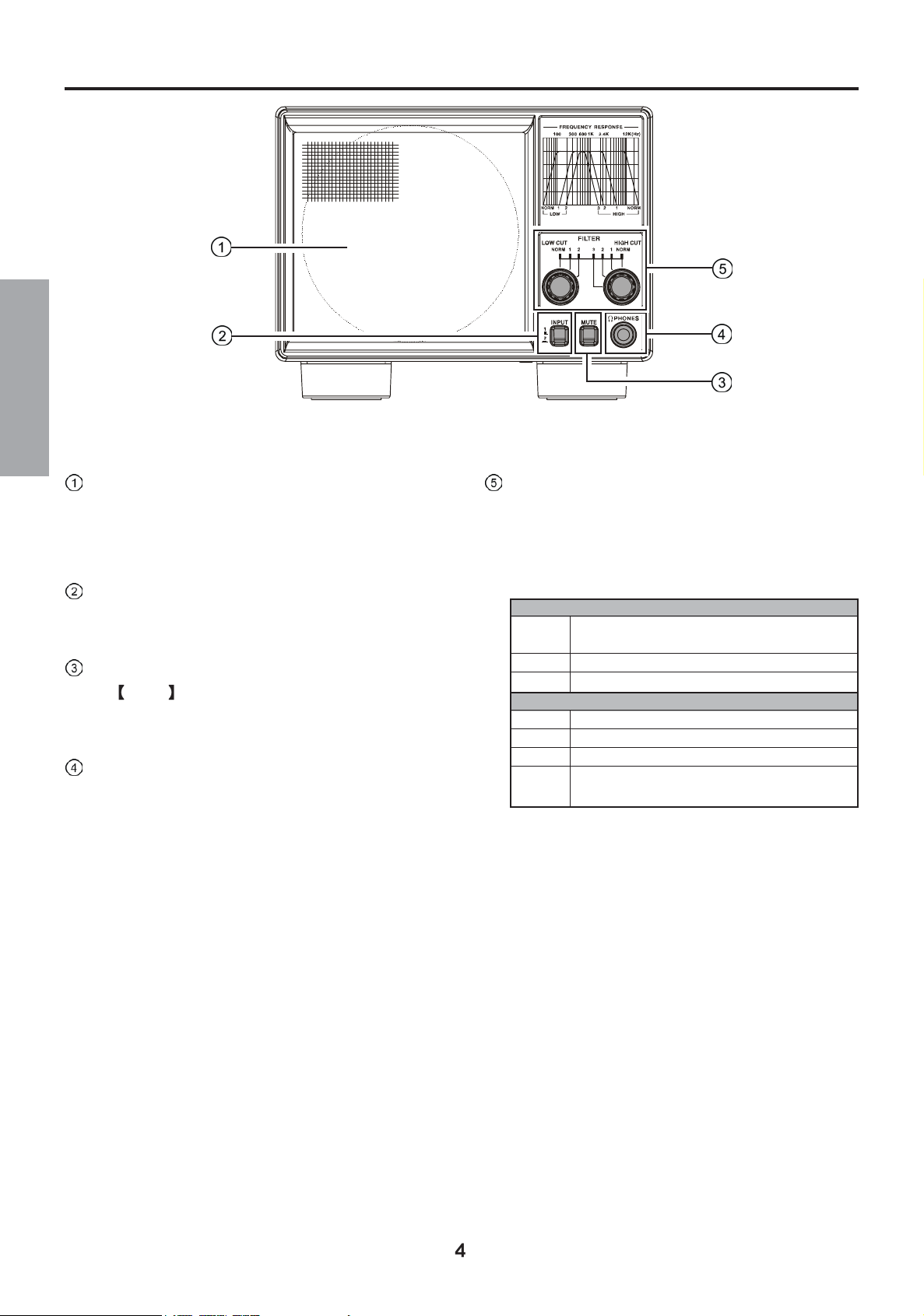
Front Panel
ENGLISH
Speaker
4.7” (120 mm) speaker is provided, with audio response
specially tailored for communications and short-wave re-
ception.
INPUT Switch
Selects between the two audio input jacks available on the
rear panel.
MUTE Switch
The MUTE switch allows you to mute the audio from
the receiver.
Headphone Jacks
A standard 1/4” headphone jack is available on the front
panel.
When a headphone plug is inserted into the jack, the
speaker will be muted.
FILTER Switch
The available audio responses are shown in the table be-
low. Three High-cut (2.4 kHz, 1 kHz, and 700 Hz) and
two Low-cut (500 Hz and 300 Hz) selections are avail-
able, plus “NORM” (no filtering applied).
LOW CUT FILTER
NORM Select this position, when not using the “LOW CUT”
filter.
1 below 300 Hz (-6dB/Oct)
2 below 500 Hz (-6dB/Oct)
HIGH CUT FILTER
3 above 700 Hz (-6dB/Oct)
2 above 1k Hz (-6dB/Oct)
1 above 2.4k Hz (-6dB/Oct)
NORM Select this position, when not using the “HIGH CUT”
filter.
Please see the “Audio Filter Frequency Response” on page 6.
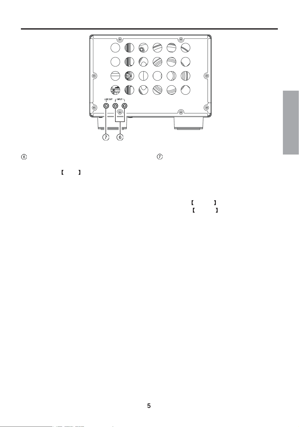
Rear Panel
ENGLISH
INPUT 1 / INPUT 2 Jack
These jacks accept input from two FT-2000 transceivers.
The front panel INPUT switch selects either jack 1 or
jack 2. When the connecting cable is inserted into the
EXT SPKR jack on the FT-2000 transceiver, the trans-
ceiver internal speaker will be muted.
This jack is gold plated, for outstanding audio performance.
LINE OUT Jack
This is an audio output jack that may be used for tape
recording or connection to other audio devices.
Audio output from this jack is conditioned by the settings
of the audio filters.
Audio output from this jack is also affected by the
transceiver's AF GAIN control(s), so you may adjust
the FT-2000 AF GAIN control for optimum output
level.
This jack is gold plated, for outstanding audio performance.
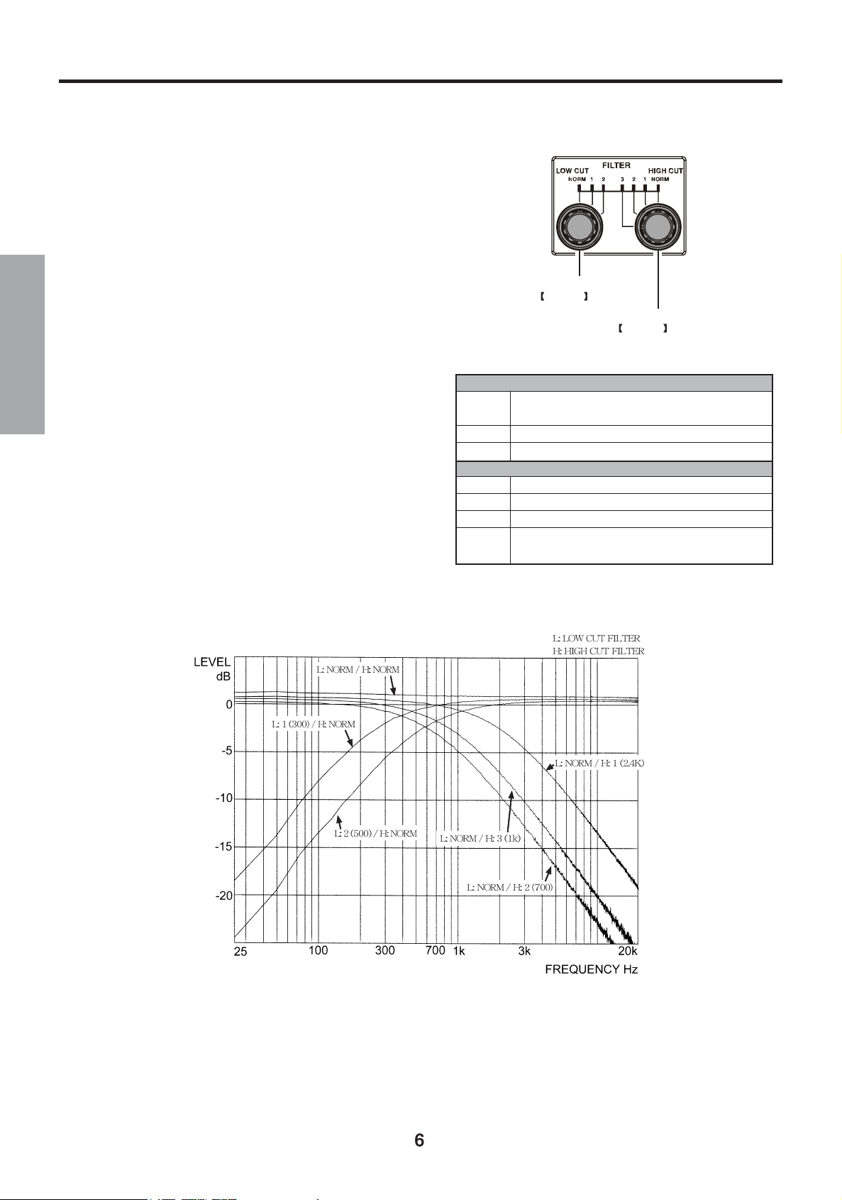
Audio Filter Operation
High-cut (2.4kHz, 1kHz, 700Hz) and Low-cut (500Hz, 300Hz) audio filters, with front-panel filter response selection.
The optimum filter setting will depend on the operating mode and band/noise conditions. For example:
PFor SSB operation
Setting the HIGH CUT filter to 2.4 kHz will cause audio
components above that frequency to be attenuated at a rate
of -6 dB per octave. This will reduce high-pitched noise,
and give the audio a more mellow sound.
FILTER
PFor CW operation
Setting LOW CUT to 500 Hz, and HIGH CUT to 700 Hz,
will create a bandpass filter with its peak at 600 Hz.
LOW CUT switch
FILTER
HIGH CUT switch
ENGLISH
PFor AM and FM operation
Begin operation in the “NORM” (Normal) position, cor-
responding to the widest fidelity available. If specific noise
or interference should arise, try engaging one or both of
the filters.
See the charts for typical response curves of these highly
useful filters. Often, reception and communications can
be significantly enhanced.
LOW CUT FILTER
NORM Select this position, when not using the “LOW CUT”
filter.
1 below 300 Hz (-6dB/Oct)
2 below 500 Hz (-6dB/Oct)
HIGH CUT FILTER
3 above 700 Hz (-6dB/Oct)
2 above 1k Hz (-6dB/Oct)
1 above 2.4k Hz (-6dB/Oct)
NORM Select this position, when not using the “HIGH CUT”
filter.
Audio Filter Frequency Response

Using the Speaker Mute Feature
Pressing the MUTE switch will allow you to silence the speaker.
Two Transceivers can be connected
MUTE switch
ENGLISH
Tow audio inputs can be connected here, and selected via the [INPUT] switch.
Two audio input jacks are available here, and selected with
the INPUT switch on the front panel. By pressing the
INPUT switch in, audio from input 2 will be heard. Press
the switch again to release it and hear the audio from input 1.
Note: It is not possible to listen to INPUT 1 and INPUT 2 at
the same time.
INPUT switch
Speaker Cable
(Supplied w/SP-2000)
Speaker Cable
(Not : p/n T9101275B)Supplied

Supplied Parts
Speaker Cables - RCA to 3.5 mm Mono - (p/n: T9101275B) ................. 1 pcs.
Specifications
Speakers
Speaker Aperture: 4.7” (120 mm)
Maximum Input: 7 Watts
Input Audio Impedance: 8-ohm
Audio Frequency Response: 200 ~ 11,000 Hz
Filter Characteristics (Cutoff Frequencies)
LOW1 Approx. 300 Hz (–6 dB/Oct)
ENGLISH
LOW2 Approx. 500 Hz (–6 dB/Oct)
HIGH1 Approx. 2.4 kHz (–6 dB/Oct)
HIGH2 Approx. 1 kHz (–6 dB/Oct)
HIGH3 Approx. 700 Hz (–6 dB/Oct)
Misc.
Case Size: 7.9” x 5.4” x 13.8” (200 x 135 x 350 mm) WHD (without knobs/jacks)
Weight: 5.5 lb (2.5 kg)

Connection Diagram
ENGLISH

Note
ENGLISH

P
P
P
P


1.
2.
スピーカーケーブル ( の )
SP-2000
付属品


スピーカーケーブル
SP-2000
(の)
付属品
オプションのスピーカーケーブル
SP-2000 T9101275B
( の と同等品:
付属
)

153-8644 4-8-8
WDXC 0120- 86- 4901


VERTEX STANDARD CO., LTD.
4-8-8 Nakameguro, Meguro-Ku, Tokyo 153-8644, Japan
VERTEX STANDARD
US Headquarters
10900 Walker Street, Cypress, CA 90630, U.S.A.
YAESU EUROPE B.V.
P.O. Box 75525, 1118 ZN Schiphol, The Netherlands
YAESU UK LTD.
Unit 12, Sun Valley Business Park, Winnall Close
Winchester, Hampshire, SO23 0LB, U.K.
VERTEX STANDARD HK LTD.
Unit 5, 20/F., Seaview Centre, 139-141 Hoi Bun Road,
Kwun Tong, Kowloon, Hong Kong
VERTEX STANDARD (AUSTRALIA) PTY., LTD.
Normanby Business Park, Unit 14/45 Normanby Road
Notting Hill 3168, Victoria, Australia
EAE95X700
0703z-CY
Copyright 2007
VERTEX STANDARD CO., LTD.
All rights reserved
No portion of this manual
may be reproduced without
the permission of
VERTEX STANDARD CO., LTD.
Printed in Japan.
 Loading...